JP2016199019A - Method for crushing deposited powder - Google Patents
Method for crushing deposited powder Download PDFInfo
- Publication number
- JP2016199019A JP2016199019A JP2015082705A JP2015082705A JP2016199019A JP 2016199019 A JP2016199019 A JP 2016199019A JP 2015082705 A JP2015082705 A JP 2015082705A JP 2015082705 A JP2015082705 A JP 2015082705A JP 2016199019 A JP2016199019 A JP 2016199019A
- Authority
- JP
- Japan
- Prior art keywords
- powder
- gas
- hopper
- deposited
- powder material
- Prior art date
- Legal status (The legal status is an assumption and is not a legal conclusion. Google has not performed a legal analysis and makes no representation as to the accuracy of the status listed.)
- Granted
Links
- 239000000843 powder Substances 0.000 title claims abstract description 196
- 238000000034 method Methods 0.000 title claims abstract description 40
- 238000002347 injection Methods 0.000 claims abstract description 31
- 239000007924 injection Substances 0.000 claims abstract description 31
- 239000000463 material Substances 0.000 abstract description 87
- 230000002776 aggregation Effects 0.000 abstract description 5
- 238000005054 agglomeration Methods 0.000 abstract 1
- 239000000243 solution Substances 0.000 abstract 1
- 239000007789 gas Substances 0.000 description 81
- 238000003860 storage Methods 0.000 description 14
- 238000004519 manufacturing process Methods 0.000 description 11
- 239000000654 additive Substances 0.000 description 10
- 230000000996 additive effect Effects 0.000 description 10
- 230000008569 process Effects 0.000 description 10
- 230000006837 decompression Effects 0.000 description 5
- 238000004220 aggregation Methods 0.000 description 4
- 239000002994 raw material Substances 0.000 description 4
- 239000011347 resin Substances 0.000 description 4
- 229920005989 resin Polymers 0.000 description 4
- 239000013307 optical fiber Substances 0.000 description 3
- XKRFYHLGVUSROY-UHFFFAOYSA-N Argon Chemical compound [Ar] XKRFYHLGVUSROY-UHFFFAOYSA-N 0.000 description 2
- 229910010272 inorganic material Inorganic materials 0.000 description 2
- 239000011147 inorganic material Substances 0.000 description 2
- 230000008018 melting Effects 0.000 description 2
- 238000002844 melting Methods 0.000 description 2
- 238000005245 sintering Methods 0.000 description 2
- IJGRMHOSHXDMSA-UHFFFAOYSA-N Atomic nitrogen Chemical compound N#N IJGRMHOSHXDMSA-UHFFFAOYSA-N 0.000 description 1
- 229910052786 argon Inorganic materials 0.000 description 1
- 230000008901 benefit Effects 0.000 description 1
- 229910010293 ceramic material Inorganic materials 0.000 description 1
- 238000012937 correction Methods 0.000 description 1
- 230000008021 deposition Effects 0.000 description 1
- 238000010586 diagram Methods 0.000 description 1
- 229910001873 dinitrogen Inorganic materials 0.000 description 1
- 238000001125 extrusion Methods 0.000 description 1
- 239000011261 inert gas Substances 0.000 description 1
- 230000001678 irradiating effect Effects 0.000 description 1
- 230000007246 mechanism Effects 0.000 description 1
- 239000002184 metal Substances 0.000 description 1
- 239000007769 metal material Substances 0.000 description 1
- 238000012986 modification Methods 0.000 description 1
- 230000004048 modification Effects 0.000 description 1
- 239000011368 organic material Substances 0.000 description 1
- 239000002245 particle Substances 0.000 description 1
- 230000002093 peripheral effect Effects 0.000 description 1
- 238000010079 rubber tapping Methods 0.000 description 1
Images


Abstract
Description
本発明は堆積粉体の破砕方法に関する。 The present invention relates to a method for crushing deposited powder.
近年、無機材料もしくは有機材料からなる粉体材料にレーザビームを照射し、焼結または溶融固化させることにより、3次元形状の積層造形物を製造する積層造形装置が注目されている。具体的には、ステージ上に粉体材料を敷き詰めて粉体層を形成する工程と、この粉体層の所定領域にレーザビ−ムを照射して焼結または溶融固化させることにより硬化層を形成する工程とを繰り返す。これにより、多数の硬化層を積層一体化して3次元形状の造形物を製造することができる。 2. Description of the Related Art In recent years, an additive manufacturing apparatus that manufactures a three-dimensional additive manufacturing object by irradiating a powder material made of an inorganic material or an organic material with a laser beam and sintering or melting and solidifying has attracted attention. Specifically, a powder layer is formed on the stage to form a powder layer, and a predetermined layer of the powder layer is irradiated with a laser beam to form a hardened layer by sintering or melting and solidifying. And repeating the process. Thus, a three-dimensional shaped object can be manufactured by stacking and integrating a large number of hardened layers.
このような積層造形装置では、ステージ上に粉体材料を供給するためのホッパーが設けられている。ホッパーはステージ上に供給する粉体材料を一時的に貯蔵する貯留槽である。ホッパーは、上側から供給された粉体材料を一時的に貯蔵し、この粉体材料を下側に設けられた排出口から排出する構造を有する。 In such an additive manufacturing apparatus, a hopper for supplying a powder material is provided on the stage. The hopper is a storage tank that temporarily stores the powder material supplied onto the stage. The hopper has a structure in which the powder material supplied from the upper side is temporarily stored and the powder material is discharged from a discharge port provided on the lower side.
特許文献1には、樹脂原料を押出成形機に供給する樹脂原料供給用ホッパーにおいて、ホッパーの排出口近傍で発生する樹脂原料のブリッジを解消することができる樹脂原料供給用ホッパーが開示されている。特許文献1に開示されている技術では、ホッパー内に堆積している粉体材料にガスを噴射することで、堆積している粉体材料を除去している。
ホッパーに貯蔵されている粉体材料がホッパーの排出口から排出される際、ホッパー内に粉体材料が堆積し、この堆積した堆積粉体によってラットホールが形成される場合がある。特許文献1に開示されている技術では、ホッパー内にガス噴射ノズルを設け、このガス噴射ノズルから堆積粉体にガスを噴射することで堆積粉体を破砕している。
When the powder material stored in the hopper is discharged from the discharge port of the hopper, the powder material may be accumulated in the hopper, and a rat hole may be formed by the deposited powder. In the technique disclosed in
しかしながら、堆積粉体にガスを噴射する際に多方向にガスを噴射した場合は、上方向に噴射されたガスによって上方向に吹き飛ばされた粉体材料が落下する際、ホッパー内に堆積している粉体材料と衝突して粉体材料同士が凝集する。このように粉体材料同士が凝集すると、積層造形装置のステージ上に粉体材料を適切に供給することができないとう問題がある。 However, if gas is injected in multiple directions when injecting gas onto the deposited powder, when the powder material blown upward by the gas injected upward falls, it accumulates in the hopper. The powder materials collide with each other and aggregate. When the powder materials are aggregated in this way, there is a problem that the powder material cannot be appropriately supplied onto the stage of the additive manufacturing apparatus.
上記課題に鑑み本発明の目的は、ホッパー内に堆積している堆積粉体を破砕する際に粉体材料同士が凝集することを抑制することが可能な堆積粉体の破砕方法を提供することである。 In view of the above problems, an object of the present invention is to provide a method for crushing a deposited powder capable of suppressing aggregation of powder materials when crushing a deposited powder deposited in a hopper. It is.
本発明にかかる堆積粉体の破砕方法は、ホッパー内に堆積している堆積粉体を破砕する堆積粉体の破砕方法であって、前記堆積粉体が堆積している位置に設けられた横方向にガスを噴射する横方向ノズルから前記堆積粉体にガスを噴射して前記堆積粉体を破砕する第1のガス噴射工程と、前記第1のガス噴射工程の後、前記堆積粉体が堆積している位置に設けられた上方向にガスを噴射する上方向ノズルと前記横方向ノズルとから前記堆積粉体にガスを噴射して前記堆積粉体を破砕する第2のガス噴射工程と、を備える。 A method for crushing a deposited powder according to the present invention is a method for crushing a deposited powder that is accumulated in a hopper, and is a lateral method provided at a position where the deposited powder is deposited. A first gas injection step of crushing the deposited powder by injecting gas into the deposited powder from a lateral nozzle that injects gas in the direction; and after the first gas injection step, A second gas injection step of crushing the deposited powder by injecting a gas into the deposited powder from an upward nozzle and a lateral nozzle, which are provided at a deposition position, and injecting the gas upward; .
本発明にかかる堆積粉体の破砕方法では、第1のガス噴射工程において横方向にガスを噴射して堆積粉体の一部を破砕した後、第2のガス噴射工程において横方向および上方向にガスを噴射している。ここで、第1のガス噴射工程において横方向にガスを噴射した後は、横方向に噴射されたガスによって堆積粉体の一部が破砕され、この破砕された粉体材料の一部が排出口から排出される。このため、第1のガス噴射工程において横方向にガスを噴射した後は粉体材料の高さ(図5のh2参照)が、横方向にガスを噴射する前の粉体材料の高さ(図4のh1参照)よりも低くなる。よって、第2のガス噴射工程において上方向にガスを噴射した際に上方向に吹き飛ばされる粉体材料の量を少なくすることができるので、粉体材料同士が衝突して凝集することを抑制することができる。 In the method for crushing deposited powder according to the present invention, after the gas is jetted in the lateral direction in the first gas injection step to crush a part of the deposited powder, the lateral direction and the upward direction in the second gas injection step. Gas is injected into the. Here, after the gas is injected in the lateral direction in the first gas injection process, a part of the deposited powder is crushed by the gas injected in the lateral direction, and a part of the crushed powder material is discharged. It is discharged from the exit. For this reason, after the gas is injected in the horizontal direction in the first gas injection step, the height of the powder material (see h2 in FIG. 5) is the height of the powder material before the gas is injected in the horizontal direction (see FIG. 5). (See h1 in FIG. 4). Therefore, when the gas is injected upward in the second gas injection step, it is possible to reduce the amount of the powder material that is blown upward, thereby suppressing the powder materials from colliding with each other. be able to.
本発明により、ホッパー内に堆積している堆積粉体を破砕する際に粉体材料同士が凝集することを抑制することが可能な堆積粉体の破砕方法を提供することができる。 ADVANTAGE OF THE INVENTION By this invention, the crushing method of the deposit powder which can suppress that powder material aggregates when crushing the deposit powder deposited in the hopper can be provided.
以下、図面を参照して本発明の実施の形態について説明する。
まず、図1を用いて本実施の形態にかかる堆積粉体の破砕方法が実施される積層造形装置の概要について説明する。図1に示すように、積層造形装置1は、ベース11、定盤12、造形槽13、造形槽支持部14、造形槽駆動部15、支柱16、支持部17、レーザスキャナ18、光ファイバ19、レーザ発振器20、粉体層形成部31、粉体分配器34、ホッパー50、減圧装置39、及び粉体貯蔵部40を備える。
Embodiments of the present invention will be described below with reference to the drawings.
First, the outline | summary of the layered manufacturing apparatus with which the crushing method of the deposit powder concerning this Embodiment is implemented using FIG. 1 is demonstrated. As shown in FIG. 1, the
ベース11は、定盤12及び支柱16を固定するための台である。ベース11は、定盤12が載置される上面が水平になるように、床面に設置される。
The
定盤12は、ベース11の水平な上面に載置、固定されている。定盤12の上面も水平であって、この定盤12の上面(ステージ)に粉体が敷き詰められ、3次元造形物27が形成されていく。図1の例では、定盤12は、四角柱状の部材である。図1に示すように、定盤12の上面の周縁全体に、水平方向に張り出したフランジ状の凸部12aが形成されている。凸部12aの外周面が全体に亘り造形槽13の内側面と接触しているため、定盤12の上面及び造形槽13の内側面に囲われた空間に、積層された粉体層26を保持することができる。本実施の形態において、粉体材料は、例えば金属材料やセラミック材料等の無機材料である。
The
造形槽13は、定盤12の上面に敷き詰められた粉体を側面から保持する筒状の部材である。造形槽13の上部開口端である造形部25に粉体層26を形成し、この粉体層26にレーザビーム22を照射することにより硬化層を形成する。また、造形槽13は、上下方向(鉛直方向)に移動可能に設置されている。つまり、硬化層を形成する度に造形槽13を定盤12に対して一定量ずつ上昇させ、3次元造形物27を形成していく。
The
造形槽支持部14は、造形槽13のフランジ部13aの上面が水平となるように、フランジ部13aの下面を支持している支持部材である。造形槽支持部14は、造形槽13を上下方向(鉛直方向)に移動させる造形槽駆動部15の連結部15cに連結されている。
The modeling
造形槽駆動部15は、造形槽13を上下方向に移動させるための駆動機構である。造形槽駆動部15は、ベース11から鉛直方向に立設された支柱16に固定されている。造形槽駆動部15は、モータ15a、ボールねじ15b、連結部15cを備える。モータ15aが駆動すると、鉛直方向に延設されたボールねじ15bが回転する。そして、ボールねじ15bが回転すると、ボールねじ15bに沿って、連結部15cが上下方向に移動する。これにより、造形槽13が上下方向に移動する。
The modeling
レーザスキャナ18は、造形槽13の上部開口端である造形部25に形成された粉体層26に対して、レーザビーム22を照射する。レーザスキャナ18は、不図示のレンズ及びミラーを備えており、レーザビーム22を水平面上において走査することができる。つまり、水平面上の任意の箇所の粉体材料を選択的に加熱して固化することができる。レーザビーム22は、レーザ発振器20において生成され、光ファイバ19を介して、レーザスキャナ18に導入される。レーザスキャナ18は、支持部17に固定されている。
The
粉体層形成部31は、造形部25に粉体材料を供給して粉体層26を形成する。粉体分配器34は、ホッパー50から配管35を介して供給された粉体材料を計量し、所定の量の粉体材料を粉体層形成部31の空隙32に投入する。つまり、粉体層形成部31は、空隙32に所定の量の粉体材料を保持し、その後、水平方向(紙面左右方向)に移動することで、造形部25に粉体層26を形成する。
The powder
具体的には、3次元造形物27を形成する際、造形槽駆動部15は造形槽13を上方向に移動する。これにより、粉体層26の最上層と造形槽13のフランジ部13aの上面との間に段差が形成される。その後、粉体層形成部31が水平方向(紙面右方向)に移動することで、粉体層26の最上層の上に新たに粉体層26が形成される。このとき、粉体層26の最上層とフランジ部13aの上面とが同一面となる(つまり、段差がなくなる)。その後、粉体層26の所定領域にレーザビ−ム22を照射して粉体層26を選択的に加熱して固化する。その後、造形槽13を上方向に移動して同様の動作を繰り返す。このように、造形槽13を上方向に移動した後、粉体層形成部31を用いて粉体層26を形成する工程と、レーザビ−ム22を用いて粉体層26を選択的に固化する工程とを繰り返すことで、3次元造形物27を形成することができる。
Specifically, when the three-
ホッパー50は、造形部25に供給する粉体材料を一時的に貯蔵する。粉体貯蔵部40は、ホッパー50に供給する粉体材料を貯蔵する。ここで、粉体貯蔵部40には3次元造形物を形成するための粉体材料が貯蔵されており、粉体貯蔵部40の容量は、ホッパー50の容量よりも十分に大きい。
The
粉体材料は、粉体貯蔵部40からホッパー50に配管41を介して搬送される。このとき、粉体材料はホッパー50側から吸引することで粉体貯蔵部40からホッパー50に搬送される。つまり、吸引部37には配管38を介して減圧装置39が接続されており、減圧装置39を用いて吸引部37を減圧することで、粉体貯蔵部40に貯蔵されている粉体材料が吸引部37側に吸引される。そして、この吸引された粉体材料がホッパー50に供給される。ホッパー50に一定量の粉体材料が搬送されると(つまり、ホッパー50の容量がいっぱいになると)、減圧装置39を停止して、粉体貯蔵部40からホッパー50への粉体材料の搬送を停止する。
The powder material is conveyed from the
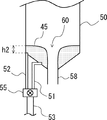
図2は、ホッパー50の詳細な構成を説明するための図である。図2に示すように、ホッパー50は、粉体貯蔵部40から供給された粉体材料45を一時的に貯蔵し、この粉体材料45を下側に設けられた排出口58から排出する。ホッパー50には、横方向(水平方向)にガスを噴射する横方向ノズル51と、上方向(垂直方向)にガスを噴射する上方向ノズル52とが設けられている。横方向ノズル51および上方向ノズル52には、配管53からアルゴンガスや窒素ガス等の不活性ガスが供給される。横方向ノズル51および上方向ノズル52と配管53との間にはバルブ55が設けられており、バルブ55の開閉を制御することで、横方向ノズル51からガスを噴射する場合、上方向ノズル52からガスを噴射する場合、並びに横方向ノズル51および上方向ノズル52からガスを噴射する場合を切り替えることができる。なお、図2では、横方向ノズル51が水平方向と平行で、上方向ノズル52が垂直方向と平行である場合を示している。しかし、本実施の形態では、横方向ノズル51が水平方向に対してある程度の角度を備えていてもよく、また上方向ノズル52が垂直方向に対してある程度の角度を備えていてもよい。
FIG. 2 is a diagram for explaining a detailed configuration of the
次に、図3〜図5を用いて、本実施の形態にかかる堆積粉体の破砕方法について説明する。ホッパー50に貯蔵されている粉体材料45がホッパー50の排出口58から排出される際、図4に示すように、ホッパー50内に粉体材料45が堆積し、この堆積した堆積粉体によって開口部60(所謂ラットホール)が形成される場合がある。つまり、ホッパー50の内壁に沿って粉体材料45が堆積し、これによってホッパー50の排出口58と対応する位置に開口部60が形成される場合がある。以下で説明する本実施の形態にかかる堆積粉体の破砕方法では、ホッパー50内に堆積している堆積粉体を破砕する方法について説明する。ここで、堆積粉体とは、開口部(ラットホール)60を形成している状態の粉体材料45を意味する。
Next, a method for crushing deposited powder according to the present embodiment will be described with reference to FIGS. When the
図3のフローチャートに示すように、まず、積層造形装置1の制御部(不図示)は、粉体貯蔵部40からホッパー50に粉体材料を搬送しているか否かを判断する(ステップS1)。例えば、減圧装置39の稼働信号を検出することで粉体材料を搬送しているか否かを判断することができる。粉体貯蔵部40からホッパー50に粉体材料を搬送していない場合(ステップS1:No)、処理を終了する。一方、粉体貯蔵部40からホッパー50に粉体材料を搬送している場合(ステップS1:Yes)、ホッパー50に貯蔵されている粉体材料45にラットホール60(図4参照)が発生しているか否かを判断する(ステップS2)。
As shown in the flowchart of FIG. 3, first, the control unit (not shown) of the
例えば、ホッパー50内にカメラを設置し、カメラで撮影された映像に画像処理を施すことでラットホール60を検出してもよい。カメラを用いてラットホール60を検出する場合は、カメラで撮影された映像に所定の画像処理を施して、ラットホールの発生を予測するようにしてもよい。また、ホッパー50から粉体分配器34に供給される粉体材料の量が低減した場合にラットホールが発生したと判断してもよい。ホッパー50に貯蔵されている粉体材料45にラットホール60が形成されていない場合(ステップS2:No)、ステップS1の処理を繰り返す。一方、ホッパー50に貯蔵されている粉体材料45にラットホール60が形成されている場合(ステップS2:Yes)、横方向ノズル51から横方向にガスを噴射する(ステップS3:第1のガス噴射工程)。これにより、ラットホール60を形成している堆積粉体(粉体材料45)の一部が破砕される。横方向にガスを噴射することでラットホール60が消滅した場合(ステップS4:Yes)、ステップS1以降の動作を繰り返す。
For example, the
一方、横方向にガスを噴射してもラットホール60が消滅しない場合(ステップS4:No)、更に、横方向ノズル51から横方向にガスを噴射し(ステップS5)、上方向ノズル52から上方向にガスを噴射する(ステップS6)。このとき、横方向ノズル51から横方向にガスを噴射した直後(例えば、1秒以内)に上方向ノズル52から上方向にガスを噴射するようにしてもよい。また、横方向ノズル51から横方向にガスを噴射するタイミングと上方向ノズル52から上方向にガスを噴射するタイミングは同時であってもよい。ステップS5およびステップS6は第2のガス噴射工程に対応している。
On the other hand, if the
ステップS3において横方向にガスを噴射した後は、横方向に噴射されたガスによって堆積粉体(粉体材料45)の一部が破砕され、この破砕された粉体材料45の一部が排出口58から排出される。このため、ステップS3において横方向にガスを噴射した後は、図5に示すように、粉体材料45の高さh2(上方向ノズル52の先端からの高さ)が、図4に示した横方向にガスを噴射する前の粉体材料45の高さh1よりも低くなる。よって、その後に上方向ノズル52から上方向にガスを噴射した際に上方向に吹き飛ばされる粉体材料の量を少なくすることができる。つまり、上方向に吹き飛ばされた粉体材料が落下する際に、ホッパー内に堆積している粉体材料と衝突して粉体材料同士が凝集するが、本実施の形態では、上方向に吹き飛ばされる粉体材料の量を少なくすることができるので、粉体材料同士の凝集を低減することができる。
After the gas is injected in the lateral direction in step S3, a part of the deposited powder (powder material 45) is crushed by the gas injected in the lateral direction, and a part of the crushed
その後、再度、ステップS4において、ラットホール60が消滅したか否かを判断し、ラットホール60が消滅するまでステップS4〜S6の動作を繰り返す。
Thereafter, in step S4, it is determined again whether or not the
上記で説明したように、ホッパー50に貯蔵されている粉体材料45がホッパー50の排出口58から排出される際、ホッパー50内に粉体材料45が堆積し、この堆積した堆積粉体によってラットホール60が形成される場合がある(図4参照)。特許文献1に開示されている技術では、ホッパー内にガス噴射ノズルを設け、このガス噴射ノズルから堆積粉体にガスを噴射することで堆積粉体を破砕している。
As described above, when the
しかしながら、堆積粉体にガスを噴射する際に多方向にガスを噴射した場合は、上方向に噴射されたガスによって上方向に吹き飛ばされた粉体材料が落下する際に、ホッパー内に堆積している粉体材料と衝突して粉体材料同士が凝集する。このように粉体材料同士が凝集すると、積層造形装置のステージ上に粉体材料を適切に供給することができないとう問題があった。特にこの問題は、積層造形装置に用いる金属粉体のように、質量が大きく、粒度が細かく、粒子間引力も発生しやすい粉体材料を用いた場合に顕著にあらわれる。 However, if gas is injected in multiple directions when injecting gas onto the deposited powder, it will accumulate in the hopper when the powder material blown upward by the gas injected upward falls. The powder materials collide with each other, and the powder materials aggregate. When the powder materials are aggregated in this way, there is a problem that the powder material cannot be appropriately supplied onto the stage of the additive manufacturing apparatus. This problem is particularly noticeable when a powder material having a large mass, a small particle size, and easily generating an interparticle attractive force, such as a metal powder used in an additive manufacturing apparatus, is used.
そこで本実施の形態にかかる堆積粉体の破砕方法では、第1のガス噴射工程(ステップS3)において横方向ノズル51から横方向にガスを噴射して堆積粉体の一部を破砕した後、第2のガス噴射工程(ステップS5、S6)において横方向ノズル51から横方向にガスを噴射し、上方向ノズル52から上方向にガスを噴射している。ここで、第1のガス噴射工程(ステップS3)において横方向にガスを噴射した後は、横方向に噴射されたガスによって堆積粉体(粉体材料45)の一部が破砕され、この破砕された粉体材料45の一部が排出口58から排出される。このため、第1のガス噴射工程(ステップS3)において横方向にガスを噴射した後は粉体材料45の高さh2(図5参照)が、図4に示した横方向にガスを噴射する前の粉体材料45の高さh1よりも低くなる。よって、第2のガス噴射工程(ステップS5、S6)において上方向ノズル52から上方向にガスを噴射した際に上方向に吹き飛ばされる粉体材料の量を少なくすることができるので、粉体材料同士が衝突して凝集することを抑制することができる。
Therefore, in the method for crushing the deposited powder according to the present embodiment, after the gas is jetted in the lateral direction from the
つまり、第1のガス噴射工程において上方向にガスを噴射した場合は、粉体材料の高さ(図4のh1参照)が高いので上方向に吹き飛ばされる粉体材料の量が多くなり、凝集する粉体材料の量も多くなる。しかし、上記で説明した本実施の形態にかかる堆積粉体の破砕方法を用いることで、上方向ノズル52から上方向にガスを噴射した際に上方向に吹き飛ばされる粉体材料の量を少なくすることができ粉体材料同士が凝集することを抑制することができる。
That is, when gas is injected upward in the first gas injection step, the amount of powder material blown upward increases because the height of the powder material (see h1 in FIG. 4) is high. The amount of powder material to be increased also increases. However, by using the method for crushing deposited powder according to the present embodiment described above, the amount of powder material blown upward when gas is injected upward from the
また、上方向に吹き飛ばされた粉体材料が落下する際、ホッパー内に堆積している粉体材料と衝突すると、衝突の衝撃により粉体材料にタッピングを行った場合と同様の現象が生じる。しかし、上記で説明した本実施の形態にかかる堆積粉体の破砕方法を用いることで、上方向ノズル52から上方向にガスを噴射した際に上方向に吹き飛ばされる粉体材料の量を少なくすることができるので、上記で説明したタッピング現象の発生を抑制することができる。
Further, when the powder material blown upward falls and collides with the powder material deposited in the hopper, a phenomenon similar to that when the powder material is tapped by the impact of the collision occurs. However, by using the method for crushing deposited powder according to the present embodiment described above, the amount of powder material blown upward when gas is injected upward from the
なお、本実施の形態では、上方向ノズル52から噴射されるガスの流量を横方向ノズル51から噴射されるガスの流量よりも小さくしてもよい。このようにすることで、上方向にガスを噴射した際に上方向に吹き飛ばされる粉体材料の量を少なくすることができる。例えば、横方向ノズル51および上方向ノズル52から噴射されるガスの流量は、バルブ55を用いて制御することができる。
In the present embodiment, the flow rate of the gas ejected from the
また、本実施の形態にかかる堆積粉体の破砕方法では、ガス噴射工程を第1のガス噴射工程(ステップS3)と第2のガス噴射工程(ステップS5、S6)とに分けて、多段構成としている。よって、例えば、第1のガス噴射工程(ステップS3)によってラットホールが消滅した場合は第2のガス噴射工程(ステップS5、S6)を省略することができるので、堆積粉体の破砕に使用するガスの量を低減することができる。 Further, in the method for crushing deposited powder according to the present embodiment, the gas injection process is divided into a first gas injection process (step S3) and a second gas injection process (steps S5 and S6), and has a multi-stage configuration. It is said. Therefore, for example, when the rat hole is extinguished by the first gas injection step (step S3), the second gas injection step (steps S5 and S6) can be omitted. The amount of gas can be reduced.
以上で説明した本実施の形態にかかる発明により、ホッパー内に堆積している堆積粉体を破砕する際に粉体材料同士が凝集することを抑制することが可能な堆積粉体の破砕方法を提供することができる。 By the invention according to the present embodiment described above, there is provided a method for crushing deposited powder capable of suppressing aggregation of powder materials when crushing deposited powder accumulated in a hopper. Can be provided.
なお、本発明は上記実施の形態に限られたものではなく、趣旨を逸脱しない範囲で適宜変更することが可能である。例えば、上記では本実施の形態にかかる堆積粉体の破砕方法を積層造形装置に適用した場合について説明したが、本実施の形態にかかる堆積粉体の破砕方法は、積層造形装置以外にも適用することができる。 Note that the present invention is not limited to the above-described embodiment, and can be changed as appropriate without departing from the spirit of the present invention. For example, the case where the method for crushing deposited powder according to the present embodiment is applied to the layered modeling apparatus has been described above, but the method for crushing deposited powder according to the present embodiment is applicable to other than the layered modeling apparatus. can do.
以上、本発明を上記実施の形態に即して説明したが、本発明は上記実施の形態の構成にのみ限定されるものではなく、本願特許請求の範囲の請求項の発明の範囲内で当業者であればなし得る各種変形、修正、組み合わせを含むことは勿論である。 Although the present invention has been described with reference to the above embodiment, the present invention is not limited only to the configuration of the above embodiment, and within the scope of the invention of the claims of the present application. It goes without saying that various modifications, corrections, and combinations that can be made by those skilled in the art are included.
1 積層造形装置
11 ベース
12 定盤
13 造形槽
14 造形槽支持部
15 造形槽駆動部
16 支柱
17 支持部
18 レーザスキャナ
19 光ファイバ
20 レーザ発振器
22 レーザビーム
25 造形部
26 粉体層
27 3次元造形物
31 粉体層形成部
34 粉体分配器
39 減圧装置
40 粉体貯蔵部
41 配管
45 粉体材料
50 ホッパー
51 横方向ノズル
52 上方向ノズル
53 配管
55 バルブ
58 排出口
60 ラットホール
DESCRIPTION OF
Claims (1)
前記堆積粉体が堆積している位置に設けられた横方向にガスを噴射する横方向ノズルから前記堆積粉体にガスを噴射して前記堆積粉体を破砕する第1のガス噴射工程と、
前記第1のガス噴射工程の後、前記堆積粉体が堆積している位置に設けられた上方向にガスを噴射する上方向ノズルと前記横方向ノズルとから前記堆積粉体にガスを噴射して前記堆積粉体を破砕する第2のガス噴射工程と、を備える、
堆積粉体の破砕方法。 A method for crushing deposited powder for crushing deposited powder accumulated in a hopper,
A first gas injection step of crushing the deposited powder by injecting a gas into the deposited powder from a lateral nozzle that injects a gas in a lateral direction provided at a position where the deposited powder is deposited;
After the first gas injection step, gas is injected into the deposited powder from an upward nozzle and a lateral nozzle, which are provided at a position where the deposited powder is deposited, and injects the gas upward. A second gas injection step of crushing the deposited powder.
A method for crushing deposited powder.
Priority Applications (1)
| Application Number | Priority Date | Filing Date | Title |
|---|---|---|---|
| JP2015082705A JP6344296B2 (en) | 2015-04-14 | 2015-04-14 | Method for crushing deposited powder |
Applications Claiming Priority (1)
| Application Number | Priority Date | Filing Date | Title |
|---|---|---|---|
| JP2015082705A JP6344296B2 (en) | 2015-04-14 | 2015-04-14 | Method for crushing deposited powder |
Publications (2)
| Publication Number | Publication Date |
|---|---|
| JP2016199019A true JP2016199019A (en) | 2016-12-01 |
| JP6344296B2 JP6344296B2 (en) | 2018-06-20 |
Family
ID=57422150
Family Applications (1)
| Application Number | Title | Priority Date | Filing Date |
|---|---|---|---|
| JP2015082705A Expired - Fee Related JP6344296B2 (en) | 2015-04-14 | 2015-04-14 | Method for crushing deposited powder |
Country Status (1)
| Country | Link |
|---|---|
| JP (1) | JP6344296B2 (en) |
Families Citing this family (1)
| Publication number | Priority date | Publication date | Assignee | Title |
|---|---|---|---|---|
| EP3774294A4 (en) * | 2018-09-28 | 2021-11-17 | Hewlett-Packard Development Company, L.P. | 3d printing system |
Citations (8)
| Publication number | Priority date | Publication date | Assignee | Title |
|---|---|---|---|---|
| US4325495A (en) * | 1979-07-16 | 1982-04-20 | Pulsonics Corporation | Storage bin activator device and method for restoring bulk material free flow |
| JPS594526A (en) * | 1982-06-29 | 1984-01-11 | Toshiba Corp | Bridging preventing device for powder in hopper |
| JPS59115285A (en) * | 1982-12-15 | 1984-07-03 | バブコツク日立株式会社 | Device for preventing clogging of powdered body storage tank |
| JPS6039333U (en) * | 1983-08-26 | 1985-03-19 | エヌオーケー株式会社 | Powder supply device |
| JPH01294482A (en) * | 1988-05-23 | 1989-11-28 | Nitta Gelatin Inc | Storage apparatus |
| JPH05286574A (en) * | 1992-04-15 | 1993-11-02 | Nippon Steel Corp | Method and device of inventory control in ore storage tank |
| JP2002211763A (en) * | 2001-01-18 | 2002-07-31 | Kurita Water Ind Ltd | Powder transportation device |
| US20080279641A1 (en) * | 2005-05-02 | 2008-11-13 | Federico Critelli | Fluidification device for granular material |
-
2015
- 2015-04-14 JP JP2015082705A patent/JP6344296B2/en not_active Expired - Fee Related
Patent Citations (8)
| Publication number | Priority date | Publication date | Assignee | Title |
|---|---|---|---|---|
| US4325495A (en) * | 1979-07-16 | 1982-04-20 | Pulsonics Corporation | Storage bin activator device and method for restoring bulk material free flow |
| JPS594526A (en) * | 1982-06-29 | 1984-01-11 | Toshiba Corp | Bridging preventing device for powder in hopper |
| JPS59115285A (en) * | 1982-12-15 | 1984-07-03 | バブコツク日立株式会社 | Device for preventing clogging of powdered body storage tank |
| JPS6039333U (en) * | 1983-08-26 | 1985-03-19 | エヌオーケー株式会社 | Powder supply device |
| JPH01294482A (en) * | 1988-05-23 | 1989-11-28 | Nitta Gelatin Inc | Storage apparatus |
| JPH05286574A (en) * | 1992-04-15 | 1993-11-02 | Nippon Steel Corp | Method and device of inventory control in ore storage tank |
| JP2002211763A (en) * | 2001-01-18 | 2002-07-31 | Kurita Water Ind Ltd | Powder transportation device |
| US20080279641A1 (en) * | 2005-05-02 | 2008-11-13 | Federico Critelli | Fluidification device for granular material |
Also Published As
| Publication number | Publication date |
|---|---|
| JP6344296B2 (en) | 2018-06-20 |
Similar Documents
| Publication | Publication Date | Title |
|---|---|---|
| CN107876759B (en) | Additive manufacturing method | |
| US20180311769A1 (en) | Multi-materials and print parameters for additive manufacturing | |
| JP7146576B2 (en) | Layered manufacturing apparatus, layered manufacturing method, and program | |
| US8961860B2 (en) | Laser build up method using vibration and apparatus | |
| US20160332371A1 (en) | Additive manufacturing system and method of operation | |
| US10173263B2 (en) | Additive manufacturing apparatus | |
| US10464301B2 (en) | Three-dimensional printing system, control device for three-dimensional printing apparatus, and control method for three-dimensional printing apparatus | |
| US10987858B2 (en) | Three dimensional continuous fabrications | |
| US20210178675A1 (en) | Vibration isolation device for an additive manufacturing machine | |
| JP6344296B2 (en) | Method for crushing deposited powder | |
| JP2017078214A (en) | Lamination molding apparatus | |
| JP2017077631A (en) | Powder lamination molding apparatus and method for manufacturing powder layer | |
| JP2017007253A (en) | Aggregation suppression device, laminate shaping apparatus, and aggregation suppression method | |
| JP2020143365A (en) | Methods for additive manufacturing with masticated particles | |
| WO2019065713A1 (en) | Supply apparatus, processing system, and processing method | |
| US20220234111A1 (en) | Method and apparatus for forming overhang structures with a metal drop ejecting three-dimensional (3d) object printer | |
| US11612937B2 (en) | Powder refill system for an additive manufacturing machine | |
| EP3685990B1 (en) | Apparatus for additively manufacturing three-dimensional objects | |
| KR20170001641A (en) | metal 3 dimension printer using plasma including double nozzles and method therefor | |
| JP2016204131A (en) | Powder supply device | |
| KR101876799B1 (en) | Three-dimensional printer | |
| US20220134645A1 (en) | Three-dimensional shaping apparatus | |
| US20220134649A1 (en) | Three-dimensional shaping apparatus | |
| US20220134437A1 (en) | Three-dimensional shaping apparatus | |
| US20220134441A1 (en) | Three-dimensional shaping apparatus |
Legal Events
| Date | Code | Title | Description |
|---|---|---|---|
| A621 | Written request for application examination |
Free format text: JAPANESE INTERMEDIATE CODE: A621 Effective date: 20170511 |
|
| A977 | Report on retrieval |
Free format text: JAPANESE INTERMEDIATE CODE: A971007 Effective date: 20180207 |
|
| A131 | Notification of reasons for refusal |
Free format text: JAPANESE INTERMEDIATE CODE: A131 Effective date: 20180220 |
|
| A521 | Request for written amendment filed |
Free format text: JAPANESE INTERMEDIATE CODE: A523 Effective date: 20180406 |
|
| TRDD | Decision of grant or rejection written | ||
| A01 | Written decision to grant a patent or to grant a registration (utility model) |
Free format text: JAPANESE INTERMEDIATE CODE: A01 Effective date: 20180424 |
|
| A61 | First payment of annual fees (during grant procedure) |
Free format text: JAPANESE INTERMEDIATE CODE: A61 Effective date: 20180507 |
|
| R151 | Written notification of patent or utility model registration |
Ref document number: 6344296 Country of ref document: JP Free format text: JAPANESE INTERMEDIATE CODE: R151 |
|
| LAPS | Cancellation because of no payment of annual fees |