JP2016196924A - Propulsion lever control system of control device of internal transmission - Google Patents
Propulsion lever control system of control device of internal transmission Download PDFInfo
- Publication number
- JP2016196924A JP2016196924A JP2015076892A JP2015076892A JP2016196924A JP 2016196924 A JP2016196924 A JP 2016196924A JP 2015076892 A JP2015076892 A JP 2015076892A JP 2015076892 A JP2015076892 A JP 2015076892A JP 2016196924 A JP2016196924 A JP 2016196924A
- Authority
- JP
- Japan
- Prior art keywords
- control
- control device
- propulsion
- control unit
- propulsion lever
- Prior art date
- Legal status (The legal status is an assumption and is not a legal conclusion. Google has not performed a legal analysis and makes no representation as to the accuracy of the status listed.)
- Granted
Links
- 230000005540 biological transmission Effects 0.000 title claims abstract description 37
- 238000006073 displacement reaction Methods 0.000 claims abstract description 17
- 238000000034 method Methods 0.000 abstract description 2
- 238000010586 diagram Methods 0.000 description 5
- 230000000694 effects Effects 0.000 description 5
- 230000035945 sensitivity Effects 0.000 description 4
- 238000004519 manufacturing process Methods 0.000 description 2
- 125000004122 cyclic group Chemical group 0.000 description 1
- 230000006866 deterioration Effects 0.000 description 1
- 238000009510 drug design Methods 0.000 description 1
- 238000012423 maintenance Methods 0.000 description 1
- 238000012986 modification Methods 0.000 description 1
- 230000004048 modification Effects 0.000 description 1
Images


Abstract
Description
本発明は、自転車に用いられる内装変速機の制御装置の推進レバー制御システムに関する。 The present invention relates to a propulsion lever control system for a control device for an internal transmission used in a bicycle.
従来の内装変速機内部の遊星歯車システムを制御する制御装置の各制御ユニットの推進レバーは、各推進レバーの移動軌跡が同一のカム(例えば、軸方向平面カム、径方向カム、内部カム、外部カム、或いはカムに類似する全てのカム)での軌道となり、カムの軌道に順に回転するのを利用して、各推進レバーが各制御ユニットのクラッチ変速を順に制御させる機能を達成させる。 The propulsion lever of each control unit of the control device for controlling the planetary gear system inside the conventional internal transmission has a cam (for example, axial plane cam, radial cam, internal cam, external The cams or all the cams similar to the cams) are used to achieve the function of causing the propulsion levers to sequentially control the clutch shifts of the control units by using the rotation of the cams in order.
しかしながら、一般的には自転車の内装変速機の制御装置は、構造が複雑なばかりか、延伸する構造の体積が大きく、重量も重く、コストも高いという問題が知られており、また、変速器が実際に変速の操縦を行う際に感度及び速度が理想からはほど遠く、これらの欠点が内装変速機及び自転車全体の品質低下をもたらした。故に、自転車の内装変速機の構造設計について、業界では革新的な技術による解決を待ち望んでいた。 However, in general, a control device for an internal transmission of a bicycle is known not only to have a complicated structure, but also to have a large volume, a heavy weight, and a high cost. However, the sensitivity and speed were far from ideal when actually maneuvering gear shifts, and these drawbacks led to a deterioration in the quality of the internal transmission and the entire bicycle. Therefore, the industry has been looking forward to innovative solutions for the structural design of bicycle interior transmissions.
また、自転車の変速器の設計上、内変速装置の歯車の運用及び経路の設計の革新のほか、内装変速機内部の相関する各制御装置の操縦を担う推進レバーの制御システムの設計及び構成部材の技術革新が、内装変速機の全体的な構造、重量、コスト、及び変速の操縦の感度と正確度により大きな影響を及ぼした。よって、いかに更なる技術革新を進め、構造の簡素化、軽量化、低コスト化、及び変速の操縦の感度の向上、変速速度の高速化、正確性の向上を図った内装変速機の制御装置が、自転車産業界が技術向上及び革新により突破すべき目標であった。 In addition to the design of bicycle transmissions, in addition to innovations in the operation of gears and paths in the internal transmission, the design and components of the control system for the propulsion lever that is responsible for the operation of the associated control devices inside the internal transmission The innovations of this technology had a major impact on the overall structure, weight, cost, and speed sensitivity and accuracy of the internal transmission. Therefore, how to further advance technological innovation, simplify the structure, reduce weight, reduce costs, improve the sensitivity of shifting operations, increase the shifting speed, and improve accuracy. However, it was a goal that the bicycle industry should break through technology improvement and innovation.
そこで、本発明者は上記の欠点が改善可能と考え、鋭意検討を重ねた結果、合理的設計で上記の課題を効果的に改善する本発明の提案に到った。 Therefore, the present inventor considered that the above-mentioned drawbacks can be improved, and as a result of intensive studies, the present inventor has arrived at a proposal of the present invention that effectively improves the above-described problems by rational design.
本発明は、上記の問題を鑑みてなされたものであり、その目的は、構造の簡素化、軽量化、低コスト化、変速操縦の感度の向上、変速の高速化、並びに正確性の向上させる内装変速機の制御装置の推進レバー制御システムを提供することにある。 The present invention has been made in view of the above-described problems, and its purpose is to simplify the structure, reduce the weight, reduce the cost, improve the sensitivity of the shift operation, increase the speed of the shift, and improve the accuracy. An object of the present invention is to provide a propulsion lever control system for a control device for an internal transmission.
上述した課題を解決し、目的を達成するために、本発明に係る内装変速機の制御装置の推進レバー制御システムは、内装変速機には少なくとも1組の遊星歯車システム及び組遊星歯車システムに対応して制御を行う制御装置が設置され、制御装置は、遊星枠或いは内部歯車の動力の入力に用いられる制御ユニット、太陽歯車を固定するか否かの制御に用いられる制御ユニット、及び遊星枠或いは内部歯車の動力の出力の制御を行う制御ユニットを備え、制御装置の推進レバーの操縦は、同一のカム(例えば、軸方向平面カム、径方向カム、内部カム、外部カム、或いはカムに類似する全てのカム)での各推進レバーの変位の軌跡を軌道として、各推進レバーの変位順序を正確に連動させ、制御装置の各推進レバーが同一のカムの操縦により対応する各制御ユニットを正確に制御させてクラッチの切り換えを達成させることを特徴とする。 In order to solve the above-mentioned problems and achieve the object, the propulsion lever control system of the control device for the internal transmission according to the present invention is compatible with at least one planetary gear system and the combined planetary gear system for the internal transmission. A control device for performing control, and the control device is a control unit used for inputting power of the planetary frame or internal gear, a control unit used for controlling whether or not the sun gear is fixed, and a planetary frame or A control unit that controls the output of the power of the internal gear is provided, and the propulsion lever of the control device is operated by the same cam (for example, an axial plane cam, a radial cam, an internal cam, an external cam, or similar to a cam) The trajectory of the displacement of each propulsion lever at all cams) is used as a trajectory, and the displacement order of each propulsion lever is accurately linked so that each propulsion lever of the control device can be controlled by operating the same cam. Precisely by controlling the respective control unit which is characterized in that to achieve the switching of the clutch.
本発明は、以下の作用効果を有する。
1.構造が簡単で、部材が少なく、体積も小さい内装変速機の制御装置の推進レバー制御システムを提供し、空間の節約及び全体重量の軽量化の効果を有効的に達成させる。
2.製造コストを下げ、全体的な製造効率を向上させる。
3.自転車の内装変速機の制御装置を有効的に簡素化させ、組み立て及びメンテナンス効率を高め、産業上の利用性及び経済効果を高める。
4.内装変速機内部の制御装置の各制御ユニットの推進レバーの変位の軌跡が、同一のカムで各推進レバーの作動を制御させる軌道となり、カムの軌道が順に回転することで、各推進レバーの正確な変位及び内装変速機内部の各制御ユニットのクラッチ変速の制御機能を提供する。
The present invention has the following effects.
1. Provided is a propulsion lever control system of a control device for an internal transmission having a simple structure, a small number of members, and a small volume, and effectively achieves the effects of saving space and reducing the overall weight.
2. Reduce manufacturing costs and improve overall manufacturing efficiency.
3. It effectively simplifies the control device of bicycle interior transmission, enhances assembly and maintenance efficiency, and enhances industrial utility and economic effect.
4). The trajectory of the displacement of the propulsion lever of each control unit of the control unit inside the internal transmission becomes the trajectory that controls the operation of each propulsion lever with the same cam. It provides a control function of the clutch shift of each control unit inside the internal displacement and the internal displacement.
本発明における実施形態について、添付図面を参照して説明する。尚、以下に説明する実施の形態は、特許請求の範囲に記載された本発明の内容を限定するものではない。また、以下に説明される構成の全てが、本発明の必須要件であるとは限らない。 Embodiments of the present invention will be described with reference to the accompanying drawings. The embodiments described below do not limit the contents of the present invention described in the claims. In addition, all of the configurations described below are not necessarily essential requirements of the present invention.
<一実施形態>
以下、本発明の一実施形態を図1〜6に基づいて説明する。図1は本発明に係る内装変速機の制御装置の推進レバー制御システムの実施形態である。内装変速機には少なくとも1組の遊星歯車システム及び組遊星歯車システムに対応して制御を行う制御装置が設置され、制御装置は、遊星枠A或いは内部歯車Rの動力の入力の制御に用いられる制御ユニットC1、太陽歯車を固定するか否かの制御に用いられる制御ユニットC2、及び遊星枠A或いは内部歯車Rの動力の出力の制御に用いられる制御ユニットC3を備える。本発明の主要な重点は、各制御ユニットの推進レバー1、推進レバー2、及び推進レバー3が制御されて同一の平面カム4で、各推進レバーの変位軌跡を軌道として、各推進レバー1、推進レバー2、及び推進レバー3の変位順序を正確に連動させ、1つのカムで各推進レバー1、推進レバー2、及び推進レバー3を操縦して対応する各制御ユニットC1、制御ユニットC2、及び制御ユニットC3を正確に制御させてのクラッチの切り換えによる変速機能を達成させる。平面カム4は軸方向平面カム、径方向カム、内部カム、外部カム、或いはカムに類似する全てのカムであり、本案の図式及び説明は最も好ましい実施形態による軸方向平面カムを例に説明するが、但し本案発明のカムの実施形態はこれに限定されない。推進レバーの変位軌跡は左右の変位軌跡、上下の変位軌跡、及び回転角度による軌跡であり、本案の図式及び説明は推進レバーの左右の変位軌跡を例に説明するが、但し本発明の実施形態はこれに限定されない。
<One Embodiment>
Hereinafter, an embodiment of the present invention will be described with reference to FIGS. FIG. 1 shows an embodiment of a propulsion lever control system of a control device for an internal transmission according to the present invention. The internal transmission is provided with at least one planetary gear system and a control device that performs control corresponding to the set planetary gear system, and the control device is used to control power input of the planetary frame A or the internal gear R. A control unit C1, a control unit C2 used for controlling whether or not the sun gear is fixed, and a control unit C3 used for controlling the power output of the planetary frame A or the internal gear R are provided. The main emphasis of the present invention is that the
また、図2は本発明が提供する5段変速の遊星歯車群を示す概念図である。制御ユニットC1は遊星枠A或いは内部歯車Rの動力を入力するためのクラッチの切り換えの制御を行い、これにより遊星枠A或いは内部歯車Rの動力を入力する変速の入力経路の切り換えを制御させる。制御ユニットC2は太陽歯車を固定するか否かによる変速の経路の切り換えの制御に用いられる。制御ユニットC3は遊星枠A或いは内部歯車Rの動力の出力による変速の出力経路の切り換えの制御に用いられる。上述の各制御ユニットC1、制御ユニットC2、及び制御ユニットC3の変速段数は図3に示す図表のように順に配列され、且つ制御ユニットC1のAはOと定義され、RはXと定義される。制御ユニットC2のS1はOと定義され、S2はXと定義される。制御ユニットC3のAはOと定義され、RはXと定義され、図4に示す図表のようになる。 FIG. 2 is a conceptual diagram showing a 5-speed planetary gear group provided by the present invention. The control unit C1 controls switching of the clutch for inputting the power of the planetary frame A or the internal gear R, and thereby controls switching of the input path of the shift for inputting the power of the planetary frame A or the internal gear R. The control unit C2 is used to control switching of the speed change path depending on whether or not the sun gear is fixed. The control unit C3 is used for controlling switching of the output path of the shift by the power output of the planetary frame A or the internal gear R. The speeds of the control units C1, C2, and C3 are arranged in order as shown in the chart of FIG. 3, and A of the control unit C1 is defined as O and R is defined as X. . S1 of the control unit C2 is defined as O and S2 is defined as X. A of the control unit C3 is defined as O, and R is defined as X, as shown in the chart of FIG.
図4によれば、3つの制御ユニットC1、制御ユニットC2、及び制御ユニットC3が1つの部材に転換されて理想的な制御状態となる(図5参照)。本発明に係る制御ユニットC1、制御ユニットC2、及び制御ユニットC3は制御順序がOOOXXXの巡回順序に符合すればよく、また、順序の配列が重疊しなければ使用可能である。なお、実際の運用において、制御ユニットC1、制御ユニットC2、及び制御ユニットC3は簡素化されて不要になり、即ち、行程が使用されず、故に5段変速を2段ないしは3段変速に簡略化させて用い、S2及び制御ユニットC2を設置させずに切り換え経路の選択時に、3段変速で運用する。この原則により、2組以上の5段変速の遊星歯車システムに拡充させ、2組で運用する実施形態になり、2つの部材(平面カム4)を制御することで5x5=25段変速の制御効果を達成させる。 According to FIG. 4, the three control units C1, C2, and C3 are converted into one member to be in an ideal control state (see FIG. 5). The control unit C1, the control unit C2, and the control unit C3 according to the present invention may be used as long as the control order matches the cyclic order of OOOXXXX, and the order arrangement does not overlap. In actual operation, the control unit C1, the control unit C2, and the control unit C3 are simplified and become unnecessary, that is, the stroke is not used, so the five-speed shift is simplified to the two-speed or three-speed shift. When the switching path is selected without installing S2 and the control unit C2, the system is operated at a three-speed shift. Based on this principle, two or more sets of five-speed planetary gear systems have been expanded to form an embodiment in which two sets are operated, and the control effect of 5 × 5 = 25-speed shift is achieved by controlling two members (planar cams 4). To achieve.
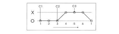
図1に示す実施形態では、各制御ユニットC1、制御ユニットC2、及び制御ユニットC3の制御点は共に左右の横移動の制御であり、平面カム4(例えば、軸方向平面カム)を利用して制御するのを例に、各制御ユニットC1、制御ユニットC2、及び制御ユニットC3の推進レバー1、推進レバー2、及び推進レバー3を制御させ、各推進レバー1、推進レバー2、及び推進レバー3が左右の移動を行程とする。上述の原則を例に、各推進レバー1、推進レバー2、及び推進レバー3の左右の移動は左がO、右がXとなり(図4参照)、図5に示す軌跡を平面カム4の軌道とし、1つの平面カム4の回転により(即ち、軌道回転)、各推進レバー1、推進レバー2、及び推進レバー3を軌道に従って対応する位置に回転させ、各推進レバーが正確な左右の横方向の変位により各制御ユニットC1、制御ユニットC2、及び制御ユニットC3のクラッチの切り換えによる変速機能の制御を達成させる。平面カム4が作動しての回転はリール、電動等の方式から選択して運用される。
In the embodiment shown in FIG. 1, the control points of each control unit C1, control unit C2, and control unit C3 are all lateral movement controls, and a flat cam 4 (for example, an axial flat cam) is used. Taking control as an example, the propulsion lever 1, the
上述の実施形態は本発明の技術思想及び特徴を説明するためのものにすぎず、当該技術分野を熟知する者に本発明の内容を理解させると共にこれをもって実施させることを目的とし、本発明の特許請求の範囲を限定するものではない。従って、本発明の精神を逸脱せずに行う各種の同様の効果をもつ改良又は変更は、請求項に含まれるものとする。 The above-described embodiments are merely for explaining the technical idea and features of the present invention, and are intended to allow those skilled in the art to understand the contents of the present invention and to carry out the same with the present invention. It is not intended to limit the scope of the claims. Accordingly, it is intended that the appended claims include modifications or variations having various similar effects that do not depart from the spirit of the invention.
1 推進レバー
2 推進レバー
3 推進レバー
4 平面カム
C1 制御ユニット
C2 制御ユニット
C3 制御ユニット
A 遊星枠
R 内部歯車
1
上述した課題を解決し、目的を達成するために、本発明に係る内装変速機の制御装置の推進レバー制御システムは、内装変速機には少なくとも1組の遊星歯車システム及び遊星歯車システムに対応して制御を行う制御装置が設置され、制御装置は、遊星枠或いは内部歯車の動力を入力する変速の入力経路の切り換えを行う制御ユニット(C1)、太陽歯車を固定するか否かによる変速の経路の切り換えを行う制御ユニット(C2)、及び遊星枠或いは内部歯車の動力の出力による変速の出力経路の切り換えを行う制御ユニット(C3)を備え、制御装置の推進レバーの操縦は、同一のカム(例えば、軸方向平面カム、径方向カム、内部カム、外部カム、或いはカムに類似する全てのカム)での各推進レバーの変位の軌跡を軌道として、各推進レバーの変位順序を正確に連動させ、制御装置の各推進レバーが同一のカムの操縦により対応する各制御ユニットを正確に制御させてクラッチの切り換えを達成させることを特徴とする。 To solve the above problems and achieve the object, propulsion lever control system of the control device of the internal transmission of the present invention, at least one pair of planetary gear system及beauty Yu star gear system in internal transmission A control device that performs control correspondingly is installed, and the control device is a control unit (C1) that switches the input path of the shift for inputting the power of the planetary frame or the internal gear, and the shift by whether the sun gear is fixed or not. control unit for switching the path (C2), and includes a planet carrier or a control unit for switching the speed change output path by the output of the power of the internal gear (C3), steering of the propulsion lever of the control device, the same Each propulsion lever displacement trajectory at a cam (for example, an axial plane cam, a radial cam, an internal cam, an external cam, or all cams similar to the cam) is used as a trajectory. In conjunction with displacement order of the lever accurately, the propulsion lever of the control device is characterized in that exactly by controlling each control unit corresponding to achieve the switching of the clutch by maneuvering of the same cam.
Claims (5)
制御装置は、遊星枠或いは内部歯車の動力の入力に用いられる制御ユニット、太陽歯車を固定するか否かの制御に用いられる制御ユニット、及び遊星枠或いは内部歯車の動力の出力の制御を行う制御ユニットを有し、
制御装置の推進レバーの操縦は、同一のカムでの各推進レバーの変位の軌跡を軌道として、各推進レバーの変位順序を正確に連動させ、制御装置の各推進レバーが同一のカムの操縦により対応する各制御ユニットを正確に制御させてクラッチの切り換えを達成させることを特徴とする内装変速機の制御装置の推進レバー制御システム。 A propulsion lever control system for a control device for an internal transmission in which at least one planetary gear system and a control device that performs control corresponding to the planetary gear system are installed,
The control device includes a control unit used to input power of the planetary frame or internal gear, a control unit used to control whether or not the sun gear is fixed, and a control that controls output of power of the planetary frame or internal gear. Has a unit,
The propulsion levers of the control device are controlled by accurately linking the displacement order of the propulsion levers with the trajectory of the displacement of each propulsion lever with the same cam as the trajectory. A propulsion lever control system for a control device of an internal transmission, wherein each corresponding control unit is accurately controlled to achieve clutch switching.
Priority Applications (1)
| Application Number | Priority Date | Filing Date | Title |
|---|---|---|---|
| JP2015076892A JP6060204B2 (en) | 2015-04-03 | 2015-04-03 | Propulsion lever control system for internal transmission control device |
Applications Claiming Priority (1)
| Application Number | Priority Date | Filing Date | Title |
|---|---|---|---|
| JP2015076892A JP6060204B2 (en) | 2015-04-03 | 2015-04-03 | Propulsion lever control system for internal transmission control device |
Publications (2)
| Publication Number | Publication Date |
|---|---|
| JP2016196924A true JP2016196924A (en) | 2016-11-24 |
| JP6060204B2 JP6060204B2 (en) | 2017-01-11 |
Family
ID=57357709
Family Applications (1)
| Application Number | Title | Priority Date | Filing Date |
|---|---|---|---|
| JP2015076892A Active JP6060204B2 (en) | 2015-04-03 | 2015-04-03 | Propulsion lever control system for internal transmission control device |
Country Status (1)
| Country | Link |
|---|---|
| JP (1) | JP6060204B2 (en) |
Citations (3)
| Publication number | Priority date | Publication date | Assignee | Title |
|---|---|---|---|---|
| JPH02216385A (en) * | 1989-02-17 | 1990-08-29 | Shimano Ind Co Ltd | Internally built speed changer for bicycle |
| JPH06179388A (en) * | 1992-12-15 | 1994-06-28 | Bridgestone Cycle Co | Transmission section for bicycle |
| JP2011126415A (en) * | 2009-12-17 | 2011-06-30 | Ntn Corp | Rear hub built-in transmission for power-assisted bicycle |
-
2015
- 2015-04-03 JP JP2015076892A patent/JP6060204B2/en active Active
Patent Citations (3)
| Publication number | Priority date | Publication date | Assignee | Title |
|---|---|---|---|---|
| JPH02216385A (en) * | 1989-02-17 | 1990-08-29 | Shimano Ind Co Ltd | Internally built speed changer for bicycle |
| JPH06179388A (en) * | 1992-12-15 | 1994-06-28 | Bridgestone Cycle Co | Transmission section for bicycle |
| JP2011126415A (en) * | 2009-12-17 | 2011-06-30 | Ntn Corp | Rear hub built-in transmission for power-assisted bicycle |
Also Published As
| Publication number | Publication date |
|---|---|
| JP6060204B2 (en) | 2017-01-11 |
Similar Documents
| Publication | Publication Date | Title |
|---|---|---|
| CN204056187U (en) | A kind of internal speed variator of bicycle | |
| CN204061754U (en) | Three gear diaxon shift speed change mechanisms | |
| CN103758993B (en) | A kind of cam gearshift of small gear-box | |
| CN105473895A (en) | Multi-stage planetary vehicle transmission | |
| CN103267093A (en) | Eight-gear planetary automatic gearbox | |
| CN104455367B (en) | Electronic engagement shell type gearshift | |
| CN103244623B (en) | A kind of nine gear planetary automatic transmissions | |
| CN108223722B (en) | Non-gear ring planet wheel speed change system and speed change method | |
| CN107339379B (en) | Movable three-gear speed change device of planetary transmission | |
| KR20100108247A (en) | Dual clutch transmission | |
| JP6060204B2 (en) | Propulsion lever control system for internal transmission control device | |
| US10132386B2 (en) | Automatic transmission for vehicle | |
| CN101480920A (en) | Four-speed gear shift device of tricycle | |
| US10041567B2 (en) | Driving control system of internal clutch | |
| JP6517502B2 (en) | Two-speed transmission | |
| CN202914649U (en) | Single planetary line two gear speed changing device | |
| JP5333094B2 (en) | Vehicle drive device | |
| JP6227587B2 (en) | Control device for internal transmission | |
| TWI565622B (en) | The lever control system of the internal transmission control mechanism | |
| CN203868258U (en) | Double-input combined-gear transmission | |
| CN105882883A (en) | Shifter lever control system of inner transmission control mechanism | |
| CN105160986A (en) | Wheel train teaching aid with combination of hand operation and automatic operation | |
| EP3067264B1 (en) | Driving control system of internal clutch | |
| JP2017008959A (en) | Gear change device of transmission | |
| CN203670749U (en) | Modularized multi-cylinder upper cover assembly |
Legal Events
| Date | Code | Title | Description |
|---|---|---|---|
| TRDD | Decision of grant or rejection written | ||
| A01 | Written decision to grant a patent or to grant a registration (utility model) |
Free format text: JAPANESE INTERMEDIATE CODE: A01 Effective date: 20161115 |
|
| A61 | First payment of annual fees (during grant procedure) |
Free format text: JAPANESE INTERMEDIATE CODE: A61 Effective date: 20161212 |
|
| R150 | Certificate of patent or registration of utility model |
Ref document number: 6060204 Country of ref document: JP Free format text: JAPANESE INTERMEDIATE CODE: R150 |
|
| R250 | Receipt of annual fees |
Free format text: JAPANESE INTERMEDIATE CODE: R250 |
|
| R250 | Receipt of annual fees |
Free format text: JAPANESE INTERMEDIATE CODE: R250 |
|
| R250 | Receipt of annual fees |
Free format text: JAPANESE INTERMEDIATE CODE: R250 |
|
| R250 | Receipt of annual fees |
Free format text: JAPANESE INTERMEDIATE CODE: R250 |
|
| R250 | Receipt of annual fees |
Free format text: JAPANESE INTERMEDIATE CODE: R250 |