JP2016196859A - Compressor, and screw rotor - Google Patents
Compressor, and screw rotor Download PDFInfo
- Publication number
- JP2016196859A JP2016196859A JP2015077318A JP2015077318A JP2016196859A JP 2016196859 A JP2016196859 A JP 2016196859A JP 2015077318 A JP2015077318 A JP 2015077318A JP 2015077318 A JP2015077318 A JP 2015077318A JP 2016196859 A JP2016196859 A JP 2016196859A
- Authority
- JP
- Japan
- Prior art keywords
- rotor
- tooth
- male
- amount
- female
- Prior art date
- Legal status (The legal status is an assumption and is not a legal conclusion. Google has not performed a legal analysis and makes no representation as to the accuracy of the status listed.)
- Granted
Links
Images


Abstract
Description
本発明は、圧縮機及びスクリューロータに係り、吸込側と、吐出側とで外径が異なるテーパ形状の圧縮機及びスクリューロータに関する。 The present invention relates to a compressor and a screw rotor, and relates to a tapered compressor and screw rotor having different outer diameters on a suction side and a discharge side.
気体を圧縮する圧縮機としてスクリュー圧縮機が知られている。
スクリュー圧縮機は、気体を圧縮する圧縮室に油を噴射注入する給油式と、注入しない無給油式があり、さらに、無給油式には水を噴射注入する水噴射式と、注入しないドライ式がある。
A screw compressor is known as a compressor for compressing gas.
There are two types of screw compressors: an oil supply type that injects and injects oil into a compression chamber that compresses gas, an oilless type that does not inject oil, and a water injection type that injects and injects water into an oilless type, and a dry type that does not inject There is.
ドライ式は油や水による圧縮空気の冷却がない断熱圧縮が行われるため、圧縮気体が高温となり、それとともに圧縮室を構成する圧縮機本体のロータやケーシングなども高温となる。また、ドライ式は油や水による潤滑効果や圧縮室からの圧縮気体の漏れを抑制するシール効果もないため、スクリュー部での直接接触駆動をせず、雌雄ロータ間やロータ・ケーシング間に微小な隙間を保った状態で高速で運転するようになっている。このため、ロータやケーシングは、運転時には熱変形により、雄雌ロータ間の隙間やロータ・ケーシング間隙間が組立時とは大きく異なり、隙間が過大となると漏れによる性能低下が又隙間が過小となると両ロータ間やロータ・ケーシング間での接触が生じて圧縮機の停止や圧縮機エアエンドの固渋が起こる可能性が増加するという問題がある。 In the dry type, adiabatic compression without cooling of compressed air by oil or water is performed, so that the compressed gas becomes high temperature, and the rotor and casing of the compressor main body constituting the compression chamber become high temperature. In addition, the dry type does not have a lubricating effect due to oil or water or a sealing effect that suppresses leakage of compressed gas from the compression chamber, so there is no direct contact drive at the screw part, and a minute amount between the male and female rotors or between the rotor and casing. It is designed to drive at a high speed with a clear gap. For this reason, the rotor and casing are subject to thermal deformation during operation, and the gap between the male and female rotors and the gap between the rotor and casing are greatly different from those during assembly. There is a problem that contact between both rotors or between the rotor and the casing increases, which increases the possibility of the compressor being stopped or the compressor air end being stuck.
このような問題を防止するために、運転時の熱変形を考慮して組立時のロータの寸法を設定、即ち組立時の隙間が大きくなるよう製作しているのが一般的である。 In order to prevent such a problem, in general, the dimensions of the rotor at the time of assembly are set in consideration of thermal deformation during operation, that is, it is manufactured so as to increase the gap at the time of assembly.
このような従来技術例として、特許文献1がある。特許文献1は、スクリューロータの形状を、運転時に温度が高くなる、即ち熱膨張量の大きい吐出側と、比較的に温度が低く熱膨張量の小さい吸込側とで径方向寸法の異なったテーパロータであって、吐出側と吸込側の断面歯形を目標とする相似に近い歯形とするために、前進面と後進面とで異なったリードを用いて、両断面の歯底における熱変形量の差分だけ外周側に移動した歯形とする複リード歯形を開示する。
There exists
特許文献1によれば、目標とする相似形状で大きさが異なる吐出側断面と吸込側断面の歯形に近い歯形形状のテーパロータを、歯面研削盤などを用いて、軸方向に沿って砥石の径方向引上量を一定にしながら加工するという通常の加工方法(以下、「引上げ加工」という。)により実現できるとしている。
According to
しかしながら、特許文献1は、両断面の歯底における熱変形量の差分を引上量とすることから、実際にはその効果をそれほど期待することができない。即ち熱変形量は径寸法に概略比例した値となるのに対し、引上量は径方向寸法によらず一定量であるため、歯底における熱変形量差だけの引上量では、歯先に近い部分では本来望まれる相似形状の歯形に対し小さい歯形となる。したがって、ロータ間の隙間やロータ・ケーシング間の隙間も、本来望まれる相似形状の歯形によって形成される隙間より大きくなる。
However, since
また、特許文献1では、雄雌各ロータにおいて、複リードの量を、目標歯形と引上歯形の干渉部を削除する量としているが、この決め方では、雄雌ロータで干渉しない部分も削除することになり、必要以上に痩せた歯形となるという課題がある。
熱変形量をより精度よく考慮したスクリューロータ及び圧縮機が望まれる。
Further, in
A screw rotor and a compressor that take into account the amount of thermal deformation with higher accuracy are desired.
上記の課題を解決するために、例えば、請求項に記載の構成を適用する。即ち少なくとも一対の雌ロータ及び雄ロータを含むスクリューロータと、前記スクリューロータと共に圧縮室を形成する圧縮機本体ケーシングとを備える圧縮機であって、雄ロータ及び雌ロータが、吐出側と吸込側の端面で、吸込側の外径が吐出側の外径よりも大となるテーパ形状を有し、雄ロータと雌ロータ夫々のテーパ量が、各ロータの吐出側及び吸込側端面の歯底の熱変形量の差以上で有ると共に歯先の熱変形量の差以下であって、且つ夫々のテーパ量の和が、一方ロータの歯底の熱変形量の差と、他方ロータの歯先の熱変形量の差との和以下である構成である。 In order to solve the above problem, for example, the configuration described in the claims is applied. That is, a compressor including a screw rotor including at least a pair of female rotors and a male rotor, and a compressor body casing that forms a compression chamber together with the screw rotors, wherein the male rotor and the female rotor are disposed on the discharge side and the suction side. The end surface has a taper shape in which the outer diameter on the suction side is larger than the outer diameter on the discharge side, and the taper amount of each of the male rotor and the female rotor is the heat of the tooth bottom on the discharge side and the suction side end face of each rotor. The difference between the amount of deformation and the difference between the amount of thermal deformation of the tooth tip and the difference of the amount of thermal deformation of the tooth tip is the sum of the respective taper amounts. It is the structure which is below the sum with the difference of deformation amount.
本発明によれば、雄雌ロータが互いに熱変形補償する歯形となり、圧縮作動室からの圧縮気体の漏れを低減することができる。
本発明の他の課題・構成・効果は、以下の記載から明らかになる。
According to the present invention, the male and female rotors have tooth shapes that compensate for thermal deformation with each other, and leakage of compressed gas from the compression working chamber can be reduced.
Other problems, configurations, and effects of the present invention will become apparent from the following description.
以下、図を用いて発明を実施するための形態について詳細に説明する。 Hereinafter, embodiments for carrying out the invention will be described in detail with reference to the drawings.
まず、図1〜5を用いて、一般的なテーパロータの従来例について述べる。
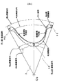
図1(a)は、スクリュー圧縮機本体(「エアエンド」ともいう。)の雄ロータ1と雌ロータ2が噛合った状態を模式的に示した斜視図である。圧縮機本体では、雄ロータ1及び雌ロータ1と、これらの外周側に設置される圧縮機本体ケーシング(不図示)とで構成される歯溝空間を圧縮室(或いは圧縮作動室)と呼ぶ。ロータが駆動源により互いに内側に回転することで、圧縮室が吐出側端面方向に進んで狭められていき、上方側に設けられた吸込口3(図では位置のみを模式的に示している。)から吸い込んだ空気が次第に圧縮されるようになっている。吐出側まで移動形成された圧縮室内の圧縮空気が、ロータ端面と略対向する位置に形成された吐出ポート4(図では位置のみを模式的に点線で示している。)から吐き出されることで、所望の圧力の空気を得るようになっている。
First, a conventional example of a general tapered rotor will be described with reference to FIGS.
FIG. 1A is a perspective view schematically showing a state in which a
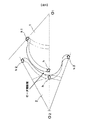
図1(b)に、上方から各ロータを観察した模式図を示す。雄ロータ1及び雌ロータ2共に吸込側の外径が大きく、吐出側に向かうにつれて外径が小となるテーパ形状となる(点線)。なお、図1(b)は、説明の便宜上吸込側と吐出側の径差を大きく表わしているが、実際の径差は僅かである。径差を設けるのは温度の違いによって生じる熱膨張の違い程度の差であることから、例えば、ロータの外径を100(mm)、ロータ材料の線膨張係数を10−5(1/K)とし、吐出側と吸込側の温度差を100(K)とすると、外径部の膨張量の差は0.1(mm)程度である。
FIG. 1B shows a schematic view of each rotor observed from above. Both the
図2に、雌ロータ2の歯形の吸込側及び吐出し側における1溝分の部分断面を模式的に示す。同図において、雌ロータ2の「吐出側歯形」は、吐出側の熱膨張前の歯形(以下、「加工歯形」という。)を示す。また、雌ロータ2の「吸込側目標歯形」は、吸込側の熱膨張前の歯形を示す。「吸込側目標歯形」の形状は、「吐出側歯形」と概略相似形状であるが、外径は、運転時の熱膨張が少ない分だけ大となる。このように、吐出側で小さく、吸込側で大きい歯形とすることにより、運転時には吐出側、吸込側でほぼ同じ大きさの歯形とし、両ロータ間やロータ・ケーシング間の隙間を適正とするようになっている。なお、O2は回転軸心であり、「吸込側歯形円」、「吐出側歯形円」は、夫々「吸込側目標歯形」及び「吐出側歯形」の最外径部分の軌跡を示す。
FIG. 2 schematically shows a partial cross section of one groove on the suction side and discharge side of the tooth profile of the
ところで、テーパロータを実際に製作する上では、吐出、吸込両側の歯形を相似形状とすることは困難である。例えば、最も一般的な歯面研削盤を用いる場合、前進面、後進面を、一定の砥石引上量とそれぞれのリードを設定して送り加工することになる(その場合の歯形の一例を、同図において「引上歯形」として示す。)。本従来例では、「吐出側歯形」と、「吸込側目標歯形」との引上量h2は、歯底の差を引上量としており、その結果、「引上歯形」の歯底径は、「吸込側目標歯形」の歯底径と一致しているが、歯先付近では「引上歯形」が「吸込側目標歯形」に対して小さくなるという現象が生ずる。このように、「吐出側歯形」と「吸込側目標歯形」の歯底の差を引上量とする方法は、「歯底基準引上げ」という。 By the way, in actually manufacturing a tapered rotor, it is difficult to make the tooth profiles on both sides of the discharge and suction similar. For example, when using the most common tooth surface grinder, the advancing surface and the reversing surface are processed by setting a constant grinding wheel lifting amount and each lead (an example of a tooth profile in that case, (Indicated in the figure as "pull tooth profile"). In this conventional example, the pull-up amount h2 between the “discharge-side tooth profile” and the “suction-side target tooth profile” is the pull-up difference, and as a result, the root diameter of the “pull-up tooth profile” is However, in the vicinity of the tooth tip, the “pull-up tooth profile” becomes smaller than the “suction-side target tooth profile”. Thus, the method of using the difference between the roots of the “discharge-side tooth profile” and the “suction-side target tooth profile” as the pull-up amount is referred to as “base-lifting”.
図3に、雄ロータ1の歯形の吸込側及び吐出し側における1溝分の部分断面を模式的に示す。「吐出側歯形」は熱膨張前の吸込側の外径形状を示し、「吸込側目標歯形」は吸込側の熱膨張前外径形状を示す。なお、O1は、回転軸であり、「吸込側歯先円」、「吐出側歯先円」は、夫々「吸込側目標歯形」及び「吐出側歯形」の最外径部分の回転軌跡を示す。
FIG. 3 schematically shows a partial cross section of one groove on the suction side and the discharge side of the tooth profile of the
雄ロータ1の場合も、「吸込側目標歯形」を目標として、砥石の引上げとリードを設定して送り加工をするが、図のように引上量h1を歯底基準とすると、雌ロータ2の場合と同様に、「引上歯形」は「吸込側目標歯形」に対して歯先付近で小さくなるという現象が生ずる。
In the case of the
図4に、雄雌両ロータの歯形の吸込側及び吐出側における1溝分の部分断面を模式的に示す。同図は、図2と図3の「引上歯形」を組み合わせた様を示しており、雌ロータ2の歯底部と、雄ロータ1の歯先部とが、軸心O1、O2の結線上に同時に位置する時、即ち両者が最も噛み合った状態を示す。この時、雌ロータ2の歯底と、雄ロータ1の歯先付近とでロータ間隙間が大きくなっている。このように、「歯底基準引上げ」の歯形どうしを組み合わせると、特に歯先付近で噛合った状態となる部分のすきまが大となり、それに伴って圧縮ガスの漏れ量が大きくなり、望ましい圧力が得られないという課題が生ずる。
FIG. 4 schematically shows a partial cross section of one groove on the suction side and discharge side of the tooth profile of both the male and female rotors. This figure shows a combination of the “pulling teeth” of FIGS. 2 and 3, where the bottom of the
以上の課題を踏まえ、図5〜図9を用いて、本発明を適用した一実施例による雄ロータ10及び雌ロータ20について説明する。本実施例では、雌雄ロータの引上量を、「歯先」における吐出側歯形と、吸込側目標歯形と径差を基準(以下、「歯先基準引上げ」という。)とすることを特徴の一つとする。
Based on the above problems, a
図5に、雌ロータ20の吸込側及び吐出側における1溝分の部分断面を模式的に示す。上述の従来例における雌ロータ2(図2)とは異なり、「吸込側目標歯形」に対し歯底部の径が大きく、歯先部の径は同等となっており、全体的には「吸込側目標歯形」より大きい歯形形状となる。即ち本実施例は、引上量を歯底部の差分であるh2から、歯先の差分X2として「歯先基準引上げ」による研磨を行ったものであり、h2<X2の関係となる。
FIG. 5 schematically shows a partial cross section for one groove on the suction side and the discharge side of the
歯先を基準に引上量を規定するのは、ロータ歯は、ロータ芯側に比して、ロータ外径側程が肉薄であるというスクリューロータの形状的な特性や、駆動源等の他の部材に接続・接触するロータシャフト寄りの芯側は、熱伝導の面で放熱効果が比較的高いという機械的な特性から、歯先側の熱膨張率が芯側よりも大となる為であり、その分駆動時における歯底部及び歯先におけるロータ間の隙間を、より狭くするのに好適で有る為である。 The amount of pull-up is defined based on the tooth tip because the rotor tooth has other characteristics such as the shape of the screw rotor that the rotor outer diameter side is thinner than the rotor core side, the drive source, etc. The core side near the rotor shaft that is connected to and contacted with the other member is because the thermal expansion coefficient on the tooth tip side is larger than that on the core side due to the mechanical characteristics that the heat dissipation effect is relatively high in terms of heat conduction. This is because it is suitable for narrowing the gap between the rotor at the tooth bottom portion and the tooth tip during driving.
図6に、雄ロータ10の吸込側及び吐出側における1溝分の部分断面を模式的に示す。雌ロータ20と同様に、引上量X1は、h1<X1として「歯先基準引上げ」によって研磨加工したものである。歯底部の径は「吸込側目標歯形」に対して大きく、歯先部の径は同等となっており、全体的には「吸込側目標歯形」より大となる。
FIG. 6 schematically shows a partial cross section for one groove on the suction side and the discharge side of the
このように、「歯先基準引上げ」によってロータの外径は大となることから、両ロータ間が噛み合った状態ではロータ間の隙間は「歯底基準引上げ」の場合よりも小となると言える。
ここで、引上量が必要以上に大となれば一方の歯先が他方の歯底と接触することから、引上量は各ロータの熱変形量を考慮する必要がある。即ち両ロータの引上量の和が、一方ロータの歯底の熱変形量の差と、他方ロータの歯先の熱変形量の差との和以下であるのが好ましい。このような関係を満たす例を以下に述べる。
Thus, since the outer diameter of the rotor is increased by the “tooth tip reference pulling up”, it can be said that the gap between the rotors is smaller than that in the case of “tooth base reference pulling up” when the rotors are engaged with each other.
Here, if the pull-up amount becomes larger than necessary, one tooth tip comes into contact with the other tooth bottom, so the pull-up amount needs to take into account the amount of thermal deformation of each rotor. That is, it is preferable that the sum of the pull-up amounts of the two rotors is equal to or less than the sum of the difference in the thermal deformation amount of the tooth bottom of one rotor and the difference of the thermal deformation amount of the tooth tip of the other rotor. An example satisfying such a relationship will be described below.
図7に、雄ロータ10を「歯底基準引上量(h2)」、雌ロータ20を「歯先基準引上量(X2)」で引き上げた場合に両ロータを組み合わせた時の1溝分の部分断面を模式的に示す。同図は、特に前進面部分について示しているが、両ロータを歯底基準引上量h1、h2としたときよりも(図4)雌ロータ20の歯底部と、雄ロータ10の歯先部とが噛み合う付近のロータ間隙間を小さくすることができる。そして、雄ロータ10の引上量h2は、より径が小である歯底部の熱膨張率を考慮した熱変形量であり又雌ロータ20の引上量X2は、より径が大である歯先部の熱膨張率を考慮した熱変形量であることから、歯底部と歯先部の径差による熱変形量を、雌雄ロータで補完し合うこととなる。これにより、圧縮ガスの漏れ量が小さくなり、性能の向上が実現できる。
FIG. 7 shows one groove when both rotors are combined when the
図8は、図7とは逆に、雄ロータ10を「歯先基準引上量(X1)」とし、雌ロータ20を「歯底基準引上量(h2)」とした場合の1溝分の部分断面を模式的に示す。この場合でも、雌ロータの歯底と、雄ロータ歯先部とがかみ合う付近のロータ間すきまを小さくすることができる。
8, contrary to FIG. 7, a portion corresponding to one groove when the
なお、図7、図8に示す例では、一方を「歯底基準引上量(h)」で、他方を「歯先基準引上量(X)」としたが、その他に、例えば両ロータの引上量を、それぞれの「歯底基準引上量(h)」と「歯先基準引上量(X)」の中間の引上量としてもよい。 In the examples shown in FIGS. 7 and 8, one is the “tooth base reference pull-up amount (h)” and the other is “tooth tip reference pull-up amount (X)”. The lifting amount may be an intermediate lifting amount between the respective “tooth base reference lifting amount (h)” and “tooth tip reference lifting amount (X)”.
他方、一方ロータを「歯底基準引上げ」、他方ロータを「歯先基準引上げ」としても、図7及び図8に斜線で示すように、雄ロータ10と、雌ロータ20との歯形が干渉する部分(以下、「干渉部T」という。)が生じる場合がある。このような場合については、どちらか一方又は両方のロータについて、複リード加工により(熱変形や設定する隙間を含めた)干渉部Tを削除する必要が生じる。
On the other hand, even if one of the rotors is set to “upper root reference pulling” and the other rotor is set to “upper tip reference pulling”, the tooth forms of the
図9を用いて、複リード加工により干渉部Tを削除する方法と、その結果形成された複リード歯形について説明する。同図は雌ロータ20及び雄ロータ10の前進面について示したものである。図中の引上歯形は図5に示した「歯先基準引上げ」による歯形であり、斜線は干渉部Tである。干渉部Tを削除するため、前進面のリードを基本のリード値に対して小さく、即ち吐出側と吸込側の巻角を大きくする。この巻角の増加分を図中の複リード回転角として示す。このリード値の変更により、「引上歯形」は、複リード歯形のように回転した形状に加工され、雄ロータ10との干渉部が削除される。図中に示す「歯底基準引上げ」歯形と比して「歯底基準引上げ」よりも大きく、雄雌両ロータが干渉しない歯形を実現することができる。
With reference to FIG. 9, a method of deleting the interference portion T by multi-lead machining and a multi-lead tooth profile formed as a result will be described. This figure shows the forward surfaces of the
このような複リード加工について、上述した図7及び図8を用いて更に説明する。
先に記したように、図7は、雌ロータ20の引上量を「歯先基準引上量(X2)」、雄ロータ10の引上量を「歯底基準引上量(h1)とした場合の、両ロータを組も合わせたロータ間隙間及び干渉部Tを示したものである。また、図8は、図7とは引上量が逆の場合を示したものである。
Such multi-lead processing will be further described with reference to FIGS. 7 and 8 described above.
As described above, FIG. 7 shows that the pulling amount of the
図7及び図8を比較すると、歯先部及び歯底部のロータ間隙間は同じ程度であるが、干渉部Tの大きさに差がある。これは、雄ロータ10と、雌ロータ20とを同じ引上量だけ引上げた場合、雌ロータ20の方が歯の枚数が多く、1溝分にわたって引上方向と径方向が近くなっているため、雄ロータ10の場合より「吸込目標歯形」に近い歯形となっているからである。干渉部Tが大きくなると、複リードによって削除する回転角の値が大きくなり、小さくする必要のない部分まで削除して痩せてしまう。したがって、雌ロータ20の引上量を雄ロータ10の引上量にくらべて大きくした図7の方法が好ましいとも言える。
7 and FIG. 8, the gap between the rotors in the tooth tip portion and the tooth bottom portion is approximately the same, but there is a difference in the size of the interference portion T. This is because when the
1…雄ロータ、2…雌ロータ、10…雄ロータ、20…雌ロータ、h1・h2…歯底基準引上量、X1・X2…歯先基準引上量、T…干渉部
DESCRIPTION OF
Claims (4)
雄ロータ及び雌ロータが、
吐出側と吸込側の端面で、吸込側の外径が吐出側の外径よりも大となるテーパ形状を有し、
雄ロータと雌ロータ夫々のテーパ量が、各ロータの吐出側及び吸込側端面の歯底の熱変形量の差以上で有ると共に歯先の熱変形量の差以下であって、且つ夫々のテーパ量の和が、一方ロータの歯底の熱変形量の差と、他方ロータの歯先の熱変形量の差との和以下である圧縮機。 A compressor comprising: a screw rotor including at least a pair of female rotors and male rotors; and a compressor body casing that forms a compression chamber together with the screw rotors,
Male and female rotors
At the discharge side and suction side end faces, the suction side has an outer diameter that is larger than the discharge side outer diameter,
The taper amount of each of the male rotor and the female rotor is greater than or equal to the difference between the thermal deformation amounts of the roots of the discharge side and suction side end surfaces of each rotor and less than the difference between the thermal deformation amounts of the tooth tips. The compressor in which the sum of the amounts is equal to or less than the sum of the difference in thermal deformation amount of the tooth bottom of one rotor and the difference in thermal deformation amount of the tooth tip of the other rotor.
雌ロータのテーパ量が、雄ロータのテーパ量より大である圧縮機。 The compressor according to claim 1 or 2,
A compressor in which the taper amount of the female rotor is larger than the taper amount of the male rotor.
雄ロータ及び雌ロータが、
吐出側と吸込側の端面で、吸込側の外径が吐出側の外径よりも大となるテーパ形状を有し、
雄ロータと雌ロータ夫々のテーパ量が、各ロータの吐出側及び吸込側端面の歯底の熱変形量の差以上で有ると共に歯先の熱変形量の差以下であって、且つ夫々のテーパ量の和が、一方ロータの歯底の熱変形量の差と、他方ロータの歯先の熱変形量の差との和以下であるスクリューロータ。 A screw rotor that includes at least a pair of female and male rotors, and compresses gas by meshing by rotation of both rotors,
Male and female rotors
At the discharge side and suction side end faces, the suction side has an outer diameter that is larger than the discharge side outer diameter,
The taper amount of each of the male rotor and the female rotor is greater than or equal to the difference between the thermal deformation amounts of the roots of the discharge side and suction side end surfaces of each rotor and less than the difference between the thermal deformation amounts of the tooth tips. A screw rotor in which the sum of the amounts is equal to or less than the sum of the difference in thermal deformation amount of the tooth bottom of one rotor and the difference of thermal deformation amount of the tooth tip of the other rotor.
Priority Applications (1)
| Application Number | Priority Date | Filing Date | Title |
|---|---|---|---|
| JP2015077318A JP6416685B2 (en) | 2015-04-06 | 2015-04-06 | Compressor, screw rotor |
Applications Claiming Priority (1)
| Application Number | Priority Date | Filing Date | Title |
|---|---|---|---|
| JP2015077318A JP6416685B2 (en) | 2015-04-06 | 2015-04-06 | Compressor, screw rotor |
Publications (2)
| Publication Number | Publication Date |
|---|---|
| JP2016196859A true JP2016196859A (en) | 2016-11-24 |
| JP6416685B2 JP6416685B2 (en) | 2018-10-31 |
Family
ID=57358180
Family Applications (1)
| Application Number | Title | Priority Date | Filing Date |
|---|---|---|---|
| JP2015077318A Active JP6416685B2 (en) | 2015-04-06 | 2015-04-06 | Compressor, screw rotor |
Country Status (1)
| Country | Link |
|---|---|
| JP (1) | JP6416685B2 (en) |
Cited By (4)
| Publication number | Priority date | Publication date | Assignee | Title |
|---|---|---|---|---|
| CN106438358A (en) * | 2016-12-07 | 2017-02-22 | 中国石油大学(华东) | Self-balancing conical screw rotor |
| WO2020044715A1 (en) * | 2018-08-29 | 2020-03-05 | 株式会社日立産機システム | Screw rotor and screw-type fluid machine main body |
| CN111749889A (en) * | 2020-05-22 | 2020-10-09 | 浙江珂勒曦动力设备股份有限公司 | Screw vacuum pump with taper |
| GB2608630A (en) * | 2021-07-08 | 2023-01-11 | Leybold Gmbh | Screw pump, screw rotor, method of manufacturing a screw rotor, and use of a screw pump or a screw rotor |
Citations (5)
| Publication number | Priority date | Publication date | Assignee | Title |
|---|---|---|---|---|
| JPS5937291A (en) * | 1982-08-27 | 1984-02-29 | Hitachi Ltd | Screw rotor |
| JPH0587075A (en) * | 1991-09-26 | 1993-04-06 | Ebara Corp | Scroll type fluid machine |
| JPH0874748A (en) * | 1994-09-09 | 1996-03-19 | Hitachi Ltd | Dry screw fluid machine |
| JP2619468B2 (en) * | 1988-04-06 | 1997-06-11 | 株式会社日立製作所 | Oil-free screw fluid machine |
| JPH10311288A (en) * | 1997-05-12 | 1998-11-24 | T D Giken:Kk | Screw type vacuum pump and screw finishing machine |
-
2015
- 2015-04-06 JP JP2015077318A patent/JP6416685B2/en active Active
Patent Citations (5)
| Publication number | Priority date | Publication date | Assignee | Title |
|---|---|---|---|---|
| JPS5937291A (en) * | 1982-08-27 | 1984-02-29 | Hitachi Ltd | Screw rotor |
| JP2619468B2 (en) * | 1988-04-06 | 1997-06-11 | 株式会社日立製作所 | Oil-free screw fluid machine |
| JPH0587075A (en) * | 1991-09-26 | 1993-04-06 | Ebara Corp | Scroll type fluid machine |
| JPH0874748A (en) * | 1994-09-09 | 1996-03-19 | Hitachi Ltd | Dry screw fluid machine |
| JPH10311288A (en) * | 1997-05-12 | 1998-11-24 | T D Giken:Kk | Screw type vacuum pump and screw finishing machine |
Cited By (10)
| Publication number | Priority date | Publication date | Assignee | Title |
|---|---|---|---|---|
| CN106438358A (en) * | 2016-12-07 | 2017-02-22 | 中国石油大学(华东) | Self-balancing conical screw rotor |
| CN106438358B (en) * | 2016-12-07 | 2018-06-05 | 中国石油大学(华东) | A kind of conical screw rotor of self-balancing |
| WO2020044715A1 (en) * | 2018-08-29 | 2020-03-05 | 株式会社日立産機システム | Screw rotor and screw-type fluid machine main body |
| TWI705185B (en) * | 2018-08-29 | 2020-09-21 | 日商日立產機系統股份有限公司 | Screw rotor and screw fluid machine body |
| CN112513465A (en) * | 2018-08-29 | 2021-03-16 | 株式会社日立产机系统 | Screw rotor and screw fluid machine body |
| JPWO2020044715A1 (en) * | 2018-08-29 | 2021-08-10 | 株式会社日立産機システム | Screw rotor and screw fluid machine body |
| JP7141459B2 (en) | 2018-08-29 | 2022-09-22 | 株式会社日立産機システム | Screw rotor and screw fluid machine body |
| US11536270B2 (en) | 2018-08-29 | 2022-12-27 | Hitachi Industrial Equipment Systems Co., Ltd. | Screw rotor and screw-type fluid machine main body |
| CN111749889A (en) * | 2020-05-22 | 2020-10-09 | 浙江珂勒曦动力设备股份有限公司 | Screw vacuum pump with taper |
| GB2608630A (en) * | 2021-07-08 | 2023-01-11 | Leybold Gmbh | Screw pump, screw rotor, method of manufacturing a screw rotor, and use of a screw pump or a screw rotor |
Also Published As
| Publication number | Publication date |
|---|---|
| JP6416685B2 (en) | 2018-10-31 |
Similar Documents
| Publication | Publication Date | Title |
|---|---|---|
| JP6416685B2 (en) | Compressor, screw rotor | |
| JP2619468B2 (en) | Oil-free screw fluid machine | |
| TWI632298B (en) | Oil-cooled screw compressor | |
| JP2008533361A (en) | Sealed and tapered screw pump / screw pressure motor | |
| TW201447147A (en) | Gear wheel with meshing teeth | |
| JP2001153073A (en) | Oil feed type screw compressor | |
| JP2010275931A (en) | Oil free screw compressor | |
| JP4570497B2 (en) | Screw rotor and tooth profile correction method for screw rotor | |
| JP2013507575A (en) | Screw rotor vacuum pump with built-in motor | |
| JP2012137000A (en) | Scroll compressor | |
| JP4821660B2 (en) | Single screw compressor | |
| JP4211871B2 (en) | Screw compressor | |
| JPH0874748A (en) | Dry screw fluid machine | |
| JP4760474B2 (en) | Screw fluid machinery | |
| CN102678564A (en) | Axial double-floating structure of scroll compressor | |
| US20160208801A1 (en) | High Pressure, Single Stage Rotor | |
| JP3701378B2 (en) | Screw rotor | |
| JP5019125B2 (en) | Method for manufacturing rotor for internal gear pump | |
| EP2881586B1 (en) | Scroll type fluid machine | |
| WO2020053976A1 (en) | Screw compressor | |
| WO2018038182A1 (en) | Scroll fluid machine | |
| US11118583B2 (en) | Scroll fluid machine with concave and convex portions in the spiral laps | |
| WO2022085631A1 (en) | Screw compressor and screw rotor | |
| JPH0125913B2 (en) | ||
| CN210127943U (en) | Screw compressor |
Legal Events
| Date | Code | Title | Description |
|---|---|---|---|
| RD04 | Notification of resignation of power of attorney |
Free format text: JAPANESE INTERMEDIATE CODE: A7424 Effective date: 20170117 |
|
| RD04 | Notification of resignation of power of attorney |
Free format text: JAPANESE INTERMEDIATE CODE: A7424 Effective date: 20170124 |
|
| A621 | Written request for application examination |
Free format text: JAPANESE INTERMEDIATE CODE: A621 Effective date: 20171115 |
|
| A521 | Written amendment |
Free format text: JAPANESE INTERMEDIATE CODE: A523 Effective date: 20171115 |
|
| TRDD | Decision of grant or rejection written | ||
| A977 | Report on retrieval |
Free format text: JAPANESE INTERMEDIATE CODE: A971007 Effective date: 20180830 |
|
| A01 | Written decision to grant a patent or to grant a registration (utility model) |
Free format text: JAPANESE INTERMEDIATE CODE: A01 Effective date: 20180904 |
|
| A61 | First payment of annual fees (during grant procedure) |
Free format text: JAPANESE INTERMEDIATE CODE: A61 Effective date: 20181004 |
|
| R150 | Certificate of patent or registration of utility model |
Ref document number: 6416685 Country of ref document: JP Free format text: JAPANESE INTERMEDIATE CODE: R150 |