JP2016193045A - Portable ultraviolet light irradiation device - Google Patents
Portable ultraviolet light irradiation device Download PDFInfo
- Publication number
- JP2016193045A JP2016193045A JP2015074376A JP2015074376A JP2016193045A JP 2016193045 A JP2016193045 A JP 2016193045A JP 2015074376 A JP2015074376 A JP 2015074376A JP 2015074376 A JP2015074376 A JP 2015074376A JP 2016193045 A JP2016193045 A JP 2016193045A
- Authority
- JP
- Japan
- Prior art keywords
- ultraviolet
- ultraviolet light
- light
- light emitting
- irradiation device
- Prior art date
- Legal status (The legal status is an assumption and is not a legal conclusion. Google has not performed a legal analysis and makes no representation as to the accuracy of the status listed.)
- Granted
Links
Images


Abstract
Description
本発明は紫外線照射装置に関し、より詳しくは、接触部のみに紫外線を照射することが可能な携帯用紫外線照射装置に関する。 The present invention relates to an ultraviolet irradiation device, and more particularly to a portable ultraviolet irradiation device capable of irradiating only a contact portion with ultraviolet rays.
従来、紫外線照射装置として様々な形態のものが知られている。 Conventionally, various types of ultraviolet irradiation devices are known.
特許文献1には、携帯可能な駆動部にランプ保護部が設けられ、該ランプ保護部にはフラッシュランプが収納され、駆動部にはフラッシュランプのパルス発光を制御する制御部が収納されていることにより、食器や歯ブラシ等の日用雑貨の殺菌を迅速に行うことができる、携帯用の紫外線照射装置が開示されている。特許文献2には、掌大の紫外線照射部と紫外線照射部に取り付けられた握り部とを備え、手等を簡易に殺菌することができる、携帯用の紫外線照射装置が開示されている。 In Patent Document 1, a lamp protection unit is provided in a portable drive unit, a flash lamp is stored in the lamp protection unit, and a control unit that controls pulse emission of the flash lamp is stored in the drive unit. Thus, a portable ultraviolet irradiation device that can quickly sterilize daily miscellaneous goods such as tableware and toothbrushes is disclosed. Patent Document 2 discloses a portable ultraviolet irradiation device that includes a palm-sized ultraviolet irradiation unit and a grip unit attached to the ultraviolet irradiation unit, and can easily sterilize a hand or the like.
特許文献1、2に開示されている紫外線照射装置は、携帯用の紫外線照射装置でありながら比較的広い領域にわたって紫外線を照射する。人体、特に目等に対して紫外線が与える影響を考慮すると、紫外線は必要な領域のみに照射されることが望ましい。 The ultraviolet irradiation devices disclosed in Patent Documents 1 and 2 irradiate ultraviolet rays over a relatively wide area even though they are portable ultraviolet irradiation devices. Considering the influence of ultraviolet rays on the human body, especially the eyes, it is desirable to irradiate only the necessary regions with ultraviolet rays.
そこで本発明は、必要な領域以外への紫外線の照射を低減することが可能な、携帯用紫外線照射装置を提供することを課題とする。 In view of the above, an object of the present invention is to provide a portable ultraviolet irradiation device capable of reducing the irradiation of ultraviolet rays outside a necessary region.
本発明の紫外線照射装置は、紫外光を出射する発光面を有する筐体と、発光面に対する物体の接触位置を検出可能に配列された複数のセンサと、発光面に向けて紫外光を発するように筐体内に配列された複数の紫外線光源と、複数の紫外線光源のそれぞれを、複数のセンサによって検出される接触位置に対応付ける制御回路とを有し、センサが発光面に対する物体の接触を検出したときに、制御回路がセンサによって検出された接触位置に対応付けられた紫外線光源を点灯させ、紫外線光源からの紫外光が前記発光面から出射されることを特徴とする。 An ultraviolet irradiation device of the present invention emits ultraviolet light toward a light emitting surface, a housing having a light emitting surface that emits ultraviolet light, a plurality of sensors arranged to detect contact positions of objects with respect to the light emitting surface, and A plurality of ultraviolet light sources arranged in the housing, and a control circuit that associates each of the plurality of ultraviolet light sources with the contact positions detected by the plurality of sensors, and the sensor detects the contact of the object with the light emitting surface. Sometimes, the control circuit turns on the ultraviolet light source associated with the contact position detected by the sensor, and the ultraviolet light from the ultraviolet light source is emitted from the light emitting surface.
本発明の紫外線照射装置において、紫外線光源が、発光波長200〜400nmの紫外発光ダイオードであることが好ましい。 In the ultraviolet irradiation device of the present invention, the ultraviolet light source is preferably an ultraviolet light emitting diode having an emission wavelength of 200 to 400 nm.
本発明の紫外線照射装置の一形態において、発光面に、紫外光を透過する複数のキーが配列されており、物体の接触によってキーが押下または押圧されたとき、該押下または押圧されたキーをセンサが特定し、該特定されたキーに対応付けられた紫外線光源が発光し、該紫外線光源からの紫外光が特定されたキーを通じて出射される構成とすることができる。 当該形態において、ぞれぞれのキーの面積が0.1〜1000mm2であることが好ましい。
また当該形態において、複数の紫外線光源が、長手方向を有し、幅方向に並べて配置された複数の導光板と、複数の導光板のそれぞれの長手方向端部に配置された、発光波長200〜400nmの紫外発光ダイオードとを有する複数の面光源であり、物体の接触によってキーが押下または押圧されたとき、該押下または押圧されたキーをセンサが特定し、該特定されたキーに対応付けられた面光源が発光し、該面光源からの紫外光が特定されたキーを通じて出射される構成とすることができる。
In one form of the ultraviolet irradiation device of the present invention, a plurality of keys that transmit ultraviolet light are arranged on the light emitting surface, and when the key is pressed or pressed by contact with an object, the pressed or pressed key is It is possible to adopt a configuration in which a sensor identifies, an ultraviolet light source associated with the identified key emits light, and ultraviolet light from the ultraviolet light source is emitted through the identified key. In this embodiment, the area of each key is preferably 0.1 to 1000 mm 2 .
Moreover, in the said form, the several ultraviolet light source has a longitudinal direction, and the light emission wavelength 200- arrange | positioned at the longitudinal direction edge part of each of the several light-guide plate arrange | positioned along with the width direction, and several light-guide plates. A plurality of surface light sources having a 400 nm ultraviolet light emitting diode, and when a key is pressed or pressed by contact of an object, the sensor specifies the pressed or pressed key and is associated with the specified key The surface light source emits light, and the ultraviolet light from the surface light source can be emitted through the specified key.
本発明の紫外線照射装置において、複数のセンサが、スイッチ、接触センサ、または感圧センサであることが好ましい。 In the ultraviolet irradiation apparatus of the present invention, the plurality of sensors are preferably switches, contact sensors, or pressure-sensitive sensors.
本発明の紫外線照射装置の他の一形態において、複数のセンサが接触センサであり、発光面が、紫外光を透過する絶縁膜を有し、接触センサは、絶縁膜の紫外光出側に形成された複数の第1電極と、絶縁膜の紫外光入側に形成された複数の第2電極と、第1電極および第2電極の一方を駆動電極とし他方を検知電極として、駆動電極に駆動信号を入力して電圧変化を与え、検知電極に生じる電圧変化に基づいて第1電極と第2電極との対向部分における静電容量の変化を検知して、当該対向部分近傍の発光面への物体の接触を検出する接触検出回路と、を有する静電容量方式の接触センサである構成とすることができる。 In another embodiment of the ultraviolet irradiation device of the present invention, the plurality of sensors are contact sensors, the light emitting surface has an insulating film that transmits ultraviolet light, and the contact sensor is formed on the ultraviolet light exit side of the insulating film. A plurality of first electrodes, a plurality of second electrodes formed on the ultraviolet light entrance side of the insulating film, one of the first electrode and the second electrode as a drive electrode, and the other as a detection electrode, driven by the drive electrode A signal is input to change the voltage, and a change in capacitance at the facing portion between the first electrode and the second electrode is detected based on the voltage change generated at the detection electrode, and the change to the light emitting surface near the facing portion is detected. It can be set as the structure which is a capacitance-type contact sensor which has the contact detection circuit which detects the contact of an object.
さらに本発明の紫外線装置の他の一形態においては、複数の第1電極および複数の第2電極は、複数の第1電極のそれぞれが発光面に沿った第1の方向に延在し、複数の第2電極のそれぞれが発光面に沿い第1の方向に対して平行でない第2の方向に延在して、発光面において二次元的に配列された複数の位置に対向部分を形成している構成とすることができる。 Furthermore, in another aspect of the ultraviolet device of the present invention, the plurality of first electrodes and the plurality of second electrodes each include a plurality of first electrodes extending in a first direction along the light emitting surface. Each of the second electrodes extends along a light emitting surface in a second direction not parallel to the first direction, and forms opposing portions at a plurality of positions two-dimensionally arranged on the light emitting surface. It can be set as a structure.
本発明によれば、必要な領域以外への紫外線の照射を低減することが可能な、携帯型の紫外線照射装置を提供することができる。 ADVANTAGE OF THE INVENTION According to this invention, the portable ultraviolet irradiation device which can reduce irradiation of the ultraviolet-ray other than a required area | region can be provided.
本発明の上記した作用および利得は、以下に説明する発明を実施するための形態から明らかにされる。以下、図面を参照しつつ、本発明の実施の形態について説明する。ただし、本発明はこれらの形態に限定されるものではない。なお、図では、一部の符号を省略することがある。 The above-mentioned operation and gain of the present invention will be clarified from embodiments for carrying out the invention described below. Hereinafter, embodiments of the present invention will be described with reference to the drawings. However, the present invention is not limited to these forms. In the drawing, some symbols may be omitted.
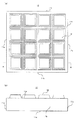
図1は、本発明の一の実施形態に係る紫外線照射装置10の構成を説明する図である。図1(a)、(b)は紫外線照射装置10の平面図および側面図をそれぞれ表している。紫外線照射装置10は、底面11a、側面11b、11c、11d、11e、及び上面11fを有する筐体11と、上面11fに押下可能に配列された、紫外線を透過する複数のキー12、12、…(以下において単に「キー12」ということがある。)とを有している。紫外線照射装置10の平面視における各キー12の面積は0.1〜1000mm2であることが好ましい。中でも、可搬性を維持しつつも、紫外線照射装置10が有するキー12の数を増やすことができ、それにより、紫外光をさらに狭い範囲を限定して照射することができるという理由から、該面積は0.1〜100mm2、さらには、0.1〜10mm2であることが最も好ましい。
FIG. 1 is a diagram illustrating a configuration of an
筐体11を構成する材料において、底面11a、側面11b、11c、11d、11eおよび上面11fは、紫外線を通さない限りにおいて特に限定されず、例えば金属や樹脂等を採用できる。さらに、筐体11の形状も特に限定されず、図1の紫外線照射装置10は箱型の筐体11を有している。
In the material constituting the housing 11, the
図2は図1(a)のA−A断面図である。紫外線照射装置10は、キー12が押下されることにより収縮し、押下力が解除されるとキー12を元の位置に復帰させる複数のバネ13、バネ13、…(以下において単に「バネ13」ということがある。)を備えている。各バネ13の一方の端部は、筐体内11内に上面11fと平行に固定された支持板14に固定されている。支持板14には、キー12、12、…の押下を検出するセンサ15、15…(以下において単に「センサ15」ということがある。)が備えられており、各キー12は、センサ15と対向するように配置され、キー12が押下されたときにセンサ15を押下する押下部12aを有している。筐体11中には筐体11の各キー12に向けて紫外線を発するように筐体内に配置された複数の紫外線光源16、16、…(以下において「紫外線光源16」ということがある。)が配置されている。また、紫外線照射装置10は制御回路17、17…(以下において単に「制御回路17」ということがある。)を有しており、複数の紫外線光源16のそれぞれを複数のセンサ15によって検出される接触位置に対応付けている。
FIG. 2 is a cross-sectional view taken along the line AA in FIG. The
紫外線光源16としては、発光波長が200nm〜400nmである紫外発光ダイオードを好適に使用できる。
As the
図3はセンサ15の機構を説明する図である。図3(a)は図2の部分拡大図であって、キー12が押下されていない姿勢を表す図であり、図3(b)は図2の部分拡大図であって、キー12が押下された姿勢を表す図である。
FIG. 3 is a view for explaining the mechanism of the
センサ15は、キー12が押下されたことを検出したとき、押下されたキー12を特定する。紫外線装置10では、センサ15としてスイッチを採用している。図3(a)はキー12が押下されていない姿勢を表した図であり、センサ15はキー12の押下または押圧を検出していない。図3(b)は、キー12が押下された姿勢を表した図である。センサ15は、キー12に備えられている押下部12aによってセンサ15が押圧されることにより、キー12が押下されたことを検出し、センサ15が押下されたキー12を特定する。そして、制御回路17がセンサ15によって特定されたキー12に対応付けられた紫外線光源16を発光させ、紫外線光源16から発せられた紫外光が特定されたキー12を通じて出射される。ここで矢印Bは、紫外線光源16から出射される紫外線の進行方向を表している。
When the
制御回路17は、複数の紫外線光源16のそれぞれを複数のセンサ15によって検出される接触位置を対応付けることができる。図4は、制御回路17の構成の一例を説明する図である。図4に示す制御回路17は、1つの紫外線光源16に対し、1つのセンサ15によって検出される接触位置を対応付けている。図4に示すように、制御回路17は導線17a、電源17b、及び電流制限抵抗17cを有している。
The control circuit 17 can associate the contact positions detected by the plurality of
図4は、キー12が押下されていない姿勢の制御回路17を表わした図であり、センサ15が開の状態にある。キー12が押下されると押下部12aがセンサ15を押圧し、センサ15が閉の状態になり、紫外線光源16が発光する。
FIG. 4 is a diagram showing the control circuit 17 in a posture in which the key 12 is not pressed, and the
よって、センサ15を備える紫外線照射装置10によれば、押下されたキー12のみを通じて該キー12が押下されている間だけ紫外線を照射することができるため、所望の時間だけ紫外線照射を行い、かつ、必要な領域以外への紫外線の照射を低減することが簡易な構造で可能となる。
Therefore, according to the
本発明に関する上記説明では、紫外線光源として点光源を用いる形態を例示したが、本発明は当該形態に限定されず、紫外線光源を面光源とする形態も可能である。図5は、そのような紫外線照射装置の他の一の実施形態に係る紫外線照射装置20を説明する図であって、図2に対応する図である。図5において、図1〜4に既に現れた要素と同一の要素には図1〜4における符号と同一の符号を付し、説明を省略する。図5(a)はキー22が押下されていない姿勢を表す図であり、図5(b)はキー22が押下された姿勢を表す図である。
In the above description of the present invention, a mode using a point light source as an ultraviolet light source has been exemplified, but the present invention is not limited to this mode, and a mode in which an ultraviolet light source is a surface light source is also possible. FIG. 5 is a view for explaining an
紫外線装置20は、キー22と、キー22に設けられた押下部22aと、面光源26と、制御回路27とを備えている。面光源26は複数の紫外線発光ダイオード26a、26a…(以下において単に「紫外線発光ダイオード26a」ということがある。)と複数の導光板26b、26b、…(以下において単に「導光板26b」ということがある。)を有しており、紫外線発光ダイオード26aは筐体11の側面に沿って列状に複数配置されている。導光板26bは長手方向を有し、幅方向に並べて配置されており、紫外線発光ダイオード26aは導光板26bのそれぞれの長手方向端部26cに対向して配置されている。紫外線発光ダイオード26aから出射された紫外線は端部26cから導光板26b内に入射し、導光板26b内部において拡散、反射され、導光板26bの出光面26dから筐体11の上面に向けて出射される。
The
ここで、紫外線発光ダイオード26aは集光光源を用いることもでき、例えば特許第5591305号公報に記載のような紫外線発光モジュールを挙げることができる。また、導光板26bは上記の働きをする導光板ならば特に限定されることなく、公知の導光板を採用することができる。面光源26から出射される紫外線の波長、すなわち紫外線発光ダイオード26aから出射される紫外線の波長は、200nm〜400nmであることが好ましい。なお、出射される紫外線には、その用途によって好ましい波長帯が存在する。例えば、紫外線照射装置を殺菌用途に用いる場合、優れた殺菌作用を有することに加え、紫外線の有するエネルギーをより効率的に細菌やウイルス等に対して与えることができるという観点から、紫外線発光ダイオード26aから出射される紫外線の波長は200〜300nmであることが好ましく、220〜290nmであることがより好ましい。
Here, the ultraviolet
図5(a)はキー22が押下されていない姿勢を表した図である。この姿勢において、センサ15はキー22の押下を検出していない。図5(b)は、キー22が押下された姿勢を表した図である。この姿勢において、キー22に備えられている押下部22aによってセンサ15が押圧されることにより、センサ15はキー22が押下されたことを検出し、押下されたキー22を特定する。そして、制御回路27がセンサ15によって特定されたキー22に対応付けられた面光源26を発光させ、面光源26から紫外光が特定されたキー22を通じて出射される。ここで図5(b)の矢印Bは、面光源26から出射される紫外線の進行方向を表している。ただし紫外線は、図中の矢印Bが記載された部分だけを照射するものではなく、面光源26の上面26d全体から照射されている。また、制御回路27には、制御回路17における紫外線光源16の代わりに、紫外発光ダイオード26bが接続されている。制御回路27は、制御回路17とこの点においてのみ異なり、そのほかは同様の構成を有している。
FIG. 5A shows a posture in which the key 22 is not pressed. In this posture, the
以上より、紫外線照射装置20によれば、紫外線光源が面光源であるため、点光源を用いる場合と比べ、光源およびセンサの数を減少することができ、紫外線照射装置を構成するためのコストを低減することができる。
From the above, according to the
本発明に関する上記説明では、キーに対する押下力が取り除かれたときにバネがキーを押下前の位置に押し戻す形態の紫外線照射装置を例示したが、本発明は当該形態に限定されない。キーに対する押下力が取り除かれたときにキーを押下前の位置に押し戻すための機構としては、公知の機構を制限なく採用することが可能である。 In the above description regarding the present invention, the ultraviolet irradiation device is illustrated in a form in which the spring pushes the key back to the position before the key is pressed when the pressing force on the key is removed, but the present invention is not limited to this mode. As a mechanism for pressing the key back to the position before pressing when the pressing force on the key is removed, a known mechanism can be adopted without limitation.
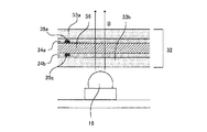
また、本発明に関する上記説明では、センサが紫外線光源の発光面側に配置された構成を例示したが、本発明は当該形態に限定されるものではない。センサが配置される位置は、紫外線光源の発光面側およびその反対側のいずれであってもよい。また、本発明に関する上記説明では、センサとしてスイッチを用いた形態を例示したが、本発明は当該形態に限定されず、センサとして接触センサや感圧センサを用いることも可能である。図6はそのような紫外線照射装置の他の一の実施形態に係る紫外線照射装置30を説明する図である。図6(a)、(b)はそれぞれ紫外線照射装置30の平面図および側面図であり、図1(a)、(b)と対応している。紫外線照射装置30は、底面31a、側面31b、31c、31d、31e、及び上面31fを有する筐体31と、上面31fに備えられた発光面32とを有する。
Moreover, in the said description regarding this invention, although the structure in which the sensor was arrange | positioned at the light emission surface side of the ultraviolet light source was illustrated, this invention is not limited to the said form. The position where the sensor is arranged may be on the light emitting surface side of the ultraviolet light source or on the opposite side. Further, in the above description of the present invention, a form using a switch as a sensor has been exemplified, but the present invention is not limited to this form, and a contact sensor or a pressure sensor can also be used as a sensor. FIG. 6 is a view for explaining an
図7は図6(a)のC−C断面の概略図であり、図8は図7の部分拡大図である。発光面32は、紫外光を透過する絶縁膜36と、ガラス基板33a、33bと、平坦化膜34a、34bと、複数の接触センサ35、35…(以下において単に「接触センサ35」ということがある。)とを有する積層体によって構成されている。なお、紫外線装置30は紫外線光源として点光源である紫外線光源16、16、…を備えているが、本発明は当該形態に限定されず、紫外線光源として面光源を用いることも可能である。
FIG. 7 is a schematic view of the CC cross section of FIG. 6A, and FIG. 8 is a partially enlarged view of FIG. The
発光面32を構成する積層体は、紫外光出側からガラス基板33a、平坦化膜34a、絶縁膜36、平坦化膜34b、ガラス基板33bの順で積層された積層構造を有している。接触センサ35は、絶縁膜36の紫外光出側の平坦化膜34a内に形成された複数の第1電極35a(検知電極)および第1電極基板35b(後述)と、絶縁膜36の紫外光入側の平坦化膜34b内に形成された複数の第2電極35c(駆動電極)および第2電極基板35d(後述)と、からなっている。ここで、紫外線照射装置30では、第1電極35aを検知電極とし、第2電極35cを駆動電極としているが、本発明は当該形態に限定されず、第1電極35aを駆動電極とし、第2電極35cを検知電極とすることも可能である。
The laminated body constituting the
図9は接触センサ35の構成を説明する図である。複数の第1電極35aは第1電極基板35bに配置されており、複数の第2電極35cは第2電極基板35dに配置されている。図9では、複数の第1電極35aのそれぞれが発光面32に沿った第1の方向に延在し、複数の第2電極35cのそれぞれが発光面32に沿い第1の方向に対して平行でない第2の方向に延在している。このようにして、第1電極35aと第2電極35cとは、発光面32において二次元的に配列された複数の位置に対向部分を形成している。
FIG. 9 is a diagram illustrating the configuration of the contact sensor 35. The plurality of
接触センサ35は、紫外線を透過する限りにおいて、その構成材料は特に限定されない。例えば、第1電極35aおよび第2電極35cは透明導電膜で形成することも可能である。また、平坦化膜34a、34bおよび絶縁膜36は、紫外線を透過する絶縁材料によって構成される限りにおいて、その態様は特に限定されない。
The constituent material of the contact sensor 35 is not particularly limited as long as it transmits ultraviolet rays. For example, the
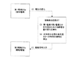
図10は接触検出回路37を説明する図である。紫外線照射装置30は接触検出回路37を有している。接触検出回路37は、(1)第2電極35c(駆動電極)に駆動信号を入力して電圧変化を与え、(2)第1電極35a(検知電極)に生じる電圧変化に基づいて、(3)第1電極35aと第2電極35cとの対向部分における静電容量の変化を検知して、(4)当該対向部分近傍の発光面32への物体の接触を検出することができる。上記(1)〜(4)は、図10に記載の番号(1)〜(4)と対応している。物体の接触を検出した接触制御回路37は、第1電極35aと第2電極35cとの対向部分における静電容量の変化した箇所と対応づけられている光源16を発光させる。
FIG. 10 is a diagram for explaining the contact detection circuit 37. The
以上、紫外線照射装置30によれば、接触センサ35を備えることにより、物体と接触した面の範囲を正確に検出できる。よって、必要な領域以外への紫外線の照射をより低減することが可能となる。
As described above, according to the
10、20、30 紫外線照射装置
11、31 筐体
11a、31a 底面
11b、31b 側面
11c、31c 側面
11e、31d 側面
11f、31f 上面
12、22 キー
12a、22a 押下部
13 バネ
14 支持板
15 センサ
16 紫外線光源(紫外発光ダイオード)
17、27 制御回路
17a 導線
17b 電源
17c 電流制限抵抗
26 面光源
26a 紫外発光ダイオード
26b 導光板
26c 端部
26d 出光面
32 発光面
33a、33b ガラス基板
34a、34b 平坦化膜
35 接触センサ
35a 第1電極
35b 第1電極基板
35c 第2電極
35d 第2電極基板
36 絶縁膜
37 接触検出回路
10, 20, 30 Ultraviolet irradiation device 11, 31
16 Ultraviolet light source (ultraviolet light emitting diode)
17, 27
Claims (8)
紫外光を出射する発光面を有する筐体と、
前記発光面に対する物体の接触位置を検出可能に配列された複数のセンサと、
前記発光面に向けて紫外光を発するように前記筐体内に配列された複数の紫外線光源と、
前記複数の紫外線光源のそれぞれを、前記複数のセンサによって検出される接触位置に対応付ける制御回路と
を有し、
前記センサが前記発光面に対する物体の接触を検出したときに、前記制御回路が前記センサによって検出された接触位置に対応付けられた紫外線光源を点灯させ、該紫外線光源からの紫外光が前記発光面から出射されることを特徴とする、携帯用紫外線照射装置。 An ultraviolet irradiation device,
A housing having a light emitting surface for emitting ultraviolet light;
A plurality of sensors arranged to detect the contact position of the object with respect to the light emitting surface;
A plurality of ultraviolet light sources arranged in the housing to emit ultraviolet light toward the light emitting surface;
A control circuit that associates each of the plurality of ultraviolet light sources with a contact position detected by the plurality of sensors;
When the sensor detects contact of an object with the light emitting surface, the control circuit turns on an ultraviolet light source corresponding to the contact position detected by the sensor, and ultraviolet light from the ultraviolet light source is emitted from the light emitting surface. A portable ultraviolet irradiation device characterized by being emitted from a portable terminal.
請求項1に記載の紫外線照射装置。 The ultraviolet light source is an ultraviolet light emitting diode having an emission wavelength of 200 to 400 nm.
The ultraviolet irradiation device according to claim 1.
物体の接触によって前記キーが押下または押圧されたとき、該押下または押圧されたキーを前記センサが特定し、該特定されたキーに対応付けられた前記紫外線光源が発光し、該紫外線光源からの紫外光が前記特定されたキーを通じて出射される、
請求項1又は2に記載の紫外線照射装置。 A plurality of keys that transmit the ultraviolet light are arranged on the light emitting surface,
When the key is pressed or pressed by contact with an object, the sensor specifies the pressed or pressed key, the ultraviolet light source associated with the specified key emits light, and UV light is emitted through the identified key,
The ultraviolet irradiation device according to claim 1 or 2.
請求項3に記載の紫外線照射装置。 The area of each of the keys is 0.1 to 1000 mm 2 ;
The ultraviolet irradiation device according to claim 3.
長手方向を有し、幅方向に並べて配置された複数の導光板と、
前記複数の導光板のそれぞれの長手方向端部に配置された、発光波長200〜400nmの紫外発光ダイオードと
を有する複数の面光源であり、
物体の接触によって前記キーが押下または押圧されたとき、該押下または押圧されたキーを前記センサが特定し、該特定されたキーに対応付けられた前記面光源が発光し、該面光源からの紫外光が前記特定されたキーを通じて出射される、
請求項3又は4に記載の紫外線照射装置。 The plurality of ultraviolet light sources are
A plurality of light guide plates having a longitudinal direction and arranged in the width direction;
A plurality of surface light sources having ultraviolet light emitting diodes having a light emission wavelength of 200 to 400 nm, arranged at respective longitudinal ends of the plurality of light guide plates;
When the key is pressed or pressed by contact with an object, the sensor specifies the pressed or pressed key, the surface light source associated with the specified key emits light, and the key from the surface light source emits light. UV light is emitted through the identified key,
The ultraviolet irradiation device according to claim 3 or 4.
請求項1〜5のいずれかに記載の紫外線照射装置。 The plurality of sensors are switches, contact sensors, or pressure sensors.
The ultraviolet irradiation device according to claim 1.
前記発光面が、前記紫外光を透過する絶縁膜を有し、
前記接触センサは、
前記絶縁膜の紫外光出側に形成された複数の第1電極と、
前記絶縁膜の紫外光入側に形成された複数の第2電極と、
前記第1電極および前記第2電極の一方を駆動電極とし他方を検知電極として、前記駆動電極に駆動信号を入力して電圧変化を与え、前記検知電極に生じる電圧変化に基づいて前記第1電極と前記第2電極との対向部分における静電容量の変化を検知して、当該対向部分近傍の前記発光面への物体の接触を検出する接触検出回路と
を有する静電容量方式の接触センサである、
請求項1又は2に記載の紫外線照射装置。 The plurality of sensors are contact sensors;
The light emitting surface has an insulating film that transmits the ultraviolet light,
The contact sensor is
A plurality of first electrodes formed on the ultraviolet light exit side of the insulating film;
A plurality of second electrodes formed on the ultraviolet light entrance side of the insulating film;
One of the first electrode and the second electrode is used as a drive electrode and the other is used as a detection electrode. A drive signal is input to the drive electrode to give a voltage change, and the first electrode based on a voltage change generated in the detection electrode And a contact detection circuit for detecting a contact of an object with the light emitting surface in the vicinity of the facing portion by detecting a change in capacitance at the facing portion between the second electrode and the second electrode. is there,
The ultraviolet irradiation device according to claim 1 or 2.
請求項7に記載の紫外線照射装置。 In the plurality of first electrodes and the plurality of second electrodes, each of the plurality of first electrodes extends in a first direction along the light emitting surface, and each of the plurality of second electrodes emits the light. Extending in a second direction that is not parallel to the first direction along the surface, and forming the opposing portions at a plurality of positions arranged two-dimensionally on the light emitting surface,
The ultraviolet irradiation device according to claim 7.
Priority Applications (1)
| Application Number | Priority Date | Filing Date | Title |
|---|---|---|---|
| JP2015074376A JP6244326B2 (en) | 2015-03-31 | 2015-03-31 | Portable UV irradiation device |
Applications Claiming Priority (1)
| Application Number | Priority Date | Filing Date | Title |
|---|---|---|---|
| JP2015074376A JP6244326B2 (en) | 2015-03-31 | 2015-03-31 | Portable UV irradiation device |
Publications (2)
| Publication Number | Publication Date |
|---|---|
| JP2016193045A true JP2016193045A (en) | 2016-11-17 |
| JP6244326B2 JP6244326B2 (en) | 2017-12-06 |
Family
ID=57323249
Family Applications (1)
| Application Number | Title | Priority Date | Filing Date |
|---|---|---|---|
| JP2015074376A Expired - Fee Related JP6244326B2 (en) | 2015-03-31 | 2015-03-31 | Portable UV irradiation device |
Country Status (1)
| Country | Link |
|---|---|
| JP (1) | JP6244326B2 (en) |
Cited By (2)
| Publication number | Priority date | Publication date | Assignee | Title |
|---|---|---|---|---|
| KR102339251B1 (en) * | 2021-05-12 | 2021-12-17 | 주식회사 콕스 | Gate-type sterilizing device with sterilizing cylinder array |
| US11895254B2 (en) | 2020-06-02 | 2024-02-06 | COMFORT VISION RESEARCH LABORATORY Co. Ltd. | Mobile terminal device |
Citations (9)
| Publication number | Priority date | Publication date | Assignee | Title |
|---|---|---|---|---|
| JPH10190058A (en) * | 1996-12-24 | 1998-07-21 | Hitachi Cable Ltd | Ultraviolet irradiator |
| US20010048379A1 (en) * | 2000-05-02 | 2001-12-06 | Terho Kaikuranta | Keypad illumination arrangement that enables dynamic and individual illumination of keys, and method of using the same |
| JP2007151807A (en) * | 2005-12-05 | 2007-06-21 | Univ Meijo | Phototherapy method by semiconductor light-emitting element, and phototherapy system by semiconductor light-emitting element |
| WO2009133870A1 (en) * | 2008-04-30 | 2009-11-05 | アルプス電気株式会社 | Illuminating apparatus and method for manufacturing the same |
| JP2010123367A (en) * | 2008-11-19 | 2010-06-03 | Alps Electric Co Ltd | Input device and method of manufacturing the same |
| US20110243789A1 (en) * | 2010-03-30 | 2011-10-06 | Roberts Jon L | Flexible Ultraviolet LED Sanitizing Apparatus |
| US20110286882A1 (en) * | 2010-05-20 | 2011-11-24 | Allan Yang Wu | Automated infection control surfaces |
| JP2013165856A (en) * | 2012-02-16 | 2013-08-29 | Nagoya City Univ | Control method of ultraviolet irradiation, and ultraviolet irradiation device |
| JP2014000406A (en) * | 2012-06-15 | 2014-01-09 | Aptar France Sas | Light pen type dispenser |
-
2015
- 2015-03-31 JP JP2015074376A patent/JP6244326B2/en not_active Expired - Fee Related
Patent Citations (9)
| Publication number | Priority date | Publication date | Assignee | Title |
|---|---|---|---|---|
| JPH10190058A (en) * | 1996-12-24 | 1998-07-21 | Hitachi Cable Ltd | Ultraviolet irradiator |
| US20010048379A1 (en) * | 2000-05-02 | 2001-12-06 | Terho Kaikuranta | Keypad illumination arrangement that enables dynamic and individual illumination of keys, and method of using the same |
| JP2007151807A (en) * | 2005-12-05 | 2007-06-21 | Univ Meijo | Phototherapy method by semiconductor light-emitting element, and phototherapy system by semiconductor light-emitting element |
| WO2009133870A1 (en) * | 2008-04-30 | 2009-11-05 | アルプス電気株式会社 | Illuminating apparatus and method for manufacturing the same |
| JP2010123367A (en) * | 2008-11-19 | 2010-06-03 | Alps Electric Co Ltd | Input device and method of manufacturing the same |
| US20110243789A1 (en) * | 2010-03-30 | 2011-10-06 | Roberts Jon L | Flexible Ultraviolet LED Sanitizing Apparatus |
| US20110286882A1 (en) * | 2010-05-20 | 2011-11-24 | Allan Yang Wu | Automated infection control surfaces |
| JP2013165856A (en) * | 2012-02-16 | 2013-08-29 | Nagoya City Univ | Control method of ultraviolet irradiation, and ultraviolet irradiation device |
| JP2014000406A (en) * | 2012-06-15 | 2014-01-09 | Aptar France Sas | Light pen type dispenser |
Cited By (2)
| Publication number | Priority date | Publication date | Assignee | Title |
|---|---|---|---|---|
| US11895254B2 (en) | 2020-06-02 | 2024-02-06 | COMFORT VISION RESEARCH LABORATORY Co. Ltd. | Mobile terminal device |
| KR102339251B1 (en) * | 2021-05-12 | 2021-12-17 | 주식회사 콕스 | Gate-type sterilizing device with sterilizing cylinder array |
Also Published As
| Publication number | Publication date |
|---|---|
| JP6244326B2 (en) | 2017-12-06 |
Similar Documents
| Publication | Publication Date | Title |
|---|---|---|
| KR101642248B1 (en) | A skin care device | |
| DK2916954T3 (en) | CIRCUIT BASED OPTION ELECTRONIC PINCETS | |
| US7530978B2 (en) | Optical hair removing device | |
| RU2006141245A (en) | CONTROL INTERFACE FOR ELECTRONIC DEVICE | |
| ATE544088T1 (en) | ILLUMINATED READING GLASSES | |
| JP2007234584A (en) | Touch sensor | |
| KR20160015082A (en) | Button device having sterilizing function | |
| TW200717864A (en) | Semiconductor light emitting device and apparatus | |
| JP6244326B2 (en) | Portable UV irradiation device | |
| KR20170103597A (en) | A skin care device | |
| US9984839B2 (en) | Illuminated keyboard | |
| KR20150025660A (en) | Portable sterilizing installation using uv-c chip led | |
| US20130199911A1 (en) | Membrane switch unit and keyboard device including the membrane switch unit | |
| US20160223151A1 (en) | Light emitting diode rail and light curing apparatus comprising same | |
| CN1936810B (en) | Device for operating optical sensors | |
| US20140362022A1 (en) | Universal stylus | |
| TW200519476A (en) | Light conducting plate and logo displaying device using the same | |
| TWI545494B (en) | Cursor device and keyboard | |
| JP2018504253A (en) | Sterilizer for portable electronic devices | |
| KR101833222B1 (en) | A backlight and a portable computer including the same | |
| JP6496198B2 (en) | Input device | |
| JP2008243655A (en) | Movable contact unit, and illumination-type panel switch composed of the same | |
| KR20160110653A (en) | Smart switch integrating tactile sensor and luminous element and method for controlling thereof | |
| KR200243871Y1 (en) | key-pad with a apparatus for emitting light | |
| US11830719B2 (en) | Light irradiation device |
Legal Events
| Date | Code | Title | Description |
|---|---|---|---|
| A621 | Written request for application examination |
Free format text: JAPANESE INTERMEDIATE CODE: A621 Effective date: 20170113 |
|
| A977 | Report on retrieval |
Free format text: JAPANESE INTERMEDIATE CODE: A971007 Effective date: 20170915 |
|
| TRDD | Decision of grant or rejection written | ||
| A01 | Written decision to grant a patent or to grant a registration (utility model) |
Free format text: JAPANESE INTERMEDIATE CODE: A01 Effective date: 20171107 |
|
| A61 | First payment of annual fees (during grant procedure) |
Free format text: JAPANESE INTERMEDIATE CODE: A61 Effective date: 20171113 |
|
| R150 | Certificate of patent or registration of utility model |
Ref document number: 6244326 Country of ref document: JP Free format text: JAPANESE INTERMEDIATE CODE: R150 |
|
| LAPS | Cancellation because of no payment of annual fees |