JP2016187191A - Image interpolation method and image interpolation apparatus - Google Patents
Image interpolation method and image interpolation apparatus Download PDFInfo
- Publication number
- JP2016187191A JP2016187191A JP2016105692A JP2016105692A JP2016187191A JP 2016187191 A JP2016187191 A JP 2016187191A JP 2016105692 A JP2016105692 A JP 2016105692A JP 2016105692 A JP2016105692 A JP 2016105692A JP 2016187191 A JP2016187191 A JP 2016187191A
- Authority
- JP
- Japan
- Prior art keywords
- unit
- filter
- pixel
- interpolation
- video
- Prior art date
- Legal status (The legal status is an assumption and is not a legal conclusion. Google has not performed a legal analysis and makes no representation as to the accuracy of the status listed.)
- Pending
Links
Images


Classifications
-
- H—ELECTRICITY
- H04—ELECTRIC COMMUNICATION TECHNIQUE
- H04N—PICTORIAL COMMUNICATION, e.g. TELEVISION
- H04N19/00—Methods or arrangements for coding, decoding, compressing or decompressing digital video signals
- H04N19/10—Methods or arrangements for coding, decoding, compressing or decompressing digital video signals using adaptive coding
- H04N19/169—Methods or arrangements for coding, decoding, compressing or decompressing digital video signals using adaptive coding characterised by the coding unit, i.e. the structural portion or semantic portion of the video signal being the object or the subject of the adaptive coding
- H04N19/17—Methods or arrangements for coding, decoding, compressing or decompressing digital video signals using adaptive coding characterised by the coding unit, i.e. the structural portion or semantic portion of the video signal being the object or the subject of the adaptive coding the unit being an image region, e.g. an object
- H04N19/176—Methods or arrangements for coding, decoding, compressing or decompressing digital video signals using adaptive coding characterised by the coding unit, i.e. the structural portion or semantic portion of the video signal being the object or the subject of the adaptive coding the unit being an image region, e.g. an object the region being a block, e.g. a macroblock
-
- G—PHYSICS
- G06—COMPUTING; CALCULATING OR COUNTING
- G06T—IMAGE DATA PROCESSING OR GENERATION, IN GENERAL
- G06T3/00—Geometric image transformation in the plane of the image
- G06T3/40—Scaling the whole image or part thereof
- G06T3/4007—Interpolation-based scaling, e.g. bilinear interpolation
-
- H—ELECTRICITY
- H04—ELECTRIC COMMUNICATION TECHNIQUE
- H04N—PICTORIAL COMMUNICATION, e.g. TELEVISION
- H04N19/00—Methods or arrangements for coding, decoding, compressing or decompressing digital video signals
- H04N19/48—Methods or arrangements for coding, decoding, compressing or decompressing digital video signals using compressed domain processing techniques other than decoding, e.g. modification of transform coefficients, variable length coding [VLC] data or run-length data
-
- G—PHYSICS
- G06—COMPUTING; CALCULATING OR COUNTING
- G06F—ELECTRIC DIGITAL DATA PROCESSING
- G06F17/00—Digital computing or data processing equipment or methods, specially adapted for specific functions
- G06F17/10—Complex mathematical operations
- G06F17/17—Function evaluation by approximation methods, e.g. inter- or extrapolation, smoothing, least mean square method
- G06F17/175—Function evaluation by approximation methods, e.g. inter- or extrapolation, smoothing, least mean square method of multidimensional data
-
- H—ELECTRICITY
- H04—ELECTRIC COMMUNICATION TECHNIQUE
- H04N—PICTORIAL COMMUNICATION, e.g. TELEVISION
- H04N19/00—Methods or arrangements for coding, decoding, compressing or decompressing digital video signals
- H04N19/10—Methods or arrangements for coding, decoding, compressing or decompressing digital video signals using adaptive coding
- H04N19/102—Methods or arrangements for coding, decoding, compressing or decompressing digital video signals using adaptive coding characterised by the element, parameter or selection affected or controlled by the adaptive coding
- H04N19/119—Adaptive subdivision aspects, e.g. subdivision of a picture into rectangular or non-rectangular coding blocks
-
- H—ELECTRICITY
- H04—ELECTRIC COMMUNICATION TECHNIQUE
- H04N—PICTORIAL COMMUNICATION, e.g. TELEVISION
- H04N19/00—Methods or arrangements for coding, decoding, compressing or decompressing digital video signals
- H04N19/10—Methods or arrangements for coding, decoding, compressing or decompressing digital video signals using adaptive coding
- H04N19/102—Methods or arrangements for coding, decoding, compressing or decompressing digital video signals using adaptive coding characterised by the element, parameter or selection affected or controlled by the adaptive coding
- H04N19/12—Selection from among a plurality of transforms or standards, e.g. selection between discrete cosine transform [DCT] and sub-band transform or selection between H.263 and H.264
- H04N19/122—Selection of transform size, e.g. 8x8 or 2x4x8 DCT; Selection of sub-band transforms of varying structure or type
-
- H—ELECTRICITY
- H04—ELECTRIC COMMUNICATION TECHNIQUE
- H04N—PICTORIAL COMMUNICATION, e.g. TELEVISION
- H04N19/00—Methods or arrangements for coding, decoding, compressing or decompressing digital video signals
- H04N19/10—Methods or arrangements for coding, decoding, compressing or decompressing digital video signals using adaptive coding
- H04N19/134—Methods or arrangements for coding, decoding, compressing or decompressing digital video signals using adaptive coding characterised by the element, parameter or criterion affecting or controlling the adaptive coding
- H04N19/136—Incoming video signal characteristics or properties
- H04N19/14—Coding unit complexity, e.g. amount of activity or edge presence estimation
-
- H—ELECTRICITY
- H04—ELECTRIC COMMUNICATION TECHNIQUE
- H04N—PICTORIAL COMMUNICATION, e.g. TELEVISION
- H04N19/00—Methods or arrangements for coding, decoding, compressing or decompressing digital video signals
- H04N19/10—Methods or arrangements for coding, decoding, compressing or decompressing digital video signals using adaptive coding
- H04N19/134—Methods or arrangements for coding, decoding, compressing or decompressing digital video signals using adaptive coding characterised by the element, parameter or criterion affecting or controlling the adaptive coding
- H04N19/154—Measured or subjectively estimated visual quality after decoding, e.g. measurement of distortion
-
- H—ELECTRICITY
- H04—ELECTRIC COMMUNICATION TECHNIQUE
- H04N—PICTORIAL COMMUNICATION, e.g. TELEVISION
- H04N19/00—Methods or arrangements for coding, decoding, compressing or decompressing digital video signals
- H04N19/10—Methods or arrangements for coding, decoding, compressing or decompressing digital video signals using adaptive coding
- H04N19/134—Methods or arrangements for coding, decoding, compressing or decompressing digital video signals using adaptive coding characterised by the element, parameter or criterion affecting or controlling the adaptive coding
- H04N19/157—Assigned coding mode, i.e. the coding mode being predefined or preselected to be further used for selection of another element or parameter
-
- H—ELECTRICITY
- H04—ELECTRIC COMMUNICATION TECHNIQUE
- H04N—PICTORIAL COMMUNICATION, e.g. TELEVISION
- H04N19/00—Methods or arrangements for coding, decoding, compressing or decompressing digital video signals
- H04N19/10—Methods or arrangements for coding, decoding, compressing or decompressing digital video signals using adaptive coding
- H04N19/169—Methods or arrangements for coding, decoding, compressing or decompressing digital video signals using adaptive coding characterised by the coding unit, i.e. the structural portion or semantic portion of the video signal being the object or the subject of the adaptive coding
- H04N19/182—Methods or arrangements for coding, decoding, compressing or decompressing digital video signals using adaptive coding characterised by the coding unit, i.e. the structural portion or semantic portion of the video signal being the object or the subject of the adaptive coding the unit being a pixel
-
- H—ELECTRICITY
- H04—ELECTRIC COMMUNICATION TECHNIQUE
- H04N—PICTORIAL COMMUNICATION, e.g. TELEVISION
- H04N19/00—Methods or arrangements for coding, decoding, compressing or decompressing digital video signals
- H04N19/30—Methods or arrangements for coding, decoding, compressing or decompressing digital video signals using hierarchical techniques, e.g. scalability
-
- H—ELECTRICITY
- H04—ELECTRIC COMMUNICATION TECHNIQUE
- H04N—PICTORIAL COMMUNICATION, e.g. TELEVISION
- H04N19/00—Methods or arrangements for coding, decoding, compressing or decompressing digital video signals
- H04N19/46—Embedding additional information in the video signal during the compression process
-
- H—ELECTRICITY
- H04—ELECTRIC COMMUNICATION TECHNIQUE
- H04N—PICTORIAL COMMUNICATION, e.g. TELEVISION
- H04N19/00—Methods or arrangements for coding, decoding, compressing or decompressing digital video signals
- H04N19/50—Methods or arrangements for coding, decoding, compressing or decompressing digital video signals using predictive coding
- H04N19/503—Methods or arrangements for coding, decoding, compressing or decompressing digital video signals using predictive coding involving temporal prediction
- H04N19/51—Motion estimation or motion compensation
- H04N19/513—Processing of motion vectors
- H04N19/517—Processing of motion vectors by encoding
- H04N19/52—Processing of motion vectors by encoding by predictive encoding
-
- H—ELECTRICITY
- H04—ELECTRIC COMMUNICATION TECHNIQUE
- H04N—PICTORIAL COMMUNICATION, e.g. TELEVISION
- H04N19/00—Methods or arrangements for coding, decoding, compressing or decompressing digital video signals
- H04N19/50—Methods or arrangements for coding, decoding, compressing or decompressing digital video signals using predictive coding
- H04N19/503—Methods or arrangements for coding, decoding, compressing or decompressing digital video signals using predictive coding involving temporal prediction
- H04N19/51—Motion estimation or motion compensation
- H04N19/523—Motion estimation or motion compensation with sub-pixel accuracy
-
- H—ELECTRICITY
- H04—ELECTRIC COMMUNICATION TECHNIQUE
- H04N—PICTORIAL COMMUNICATION, e.g. TELEVISION
- H04N19/00—Methods or arrangements for coding, decoding, compressing or decompressing digital video signals
- H04N19/50—Methods or arrangements for coding, decoding, compressing or decompressing digital video signals using predictive coding
- H04N19/59—Methods or arrangements for coding, decoding, compressing or decompressing digital video signals using predictive coding involving spatial sub-sampling or interpolation, e.g. alteration of picture size or resolution
-
- H—ELECTRICITY
- H04—ELECTRIC COMMUNICATION TECHNIQUE
- H04N—PICTORIAL COMMUNICATION, e.g. TELEVISION
- H04N19/00—Methods or arrangements for coding, decoding, compressing or decompressing digital video signals
- H04N19/80—Details of filtering operations specially adapted for video compression, e.g. for pixel interpolation
- H04N19/82—Details of filtering operations specially adapted for video compression, e.g. for pixel interpolation involving filtering within a prediction loop
-
- H—ELECTRICITY
- H04—ELECTRIC COMMUNICATION TECHNIQUE
- H04N—PICTORIAL COMMUNICATION, e.g. TELEVISION
- H04N19/00—Methods or arrangements for coding, decoding, compressing or decompressing digital video signals
- H04N19/85—Methods or arrangements for coding, decoding, compressing or decompressing digital video signals using pre-processing or post-processing specially adapted for video compression
- H04N19/86—Methods or arrangements for coding, decoding, compressing or decompressing digital video signals using pre-processing or post-processing specially adapted for video compression involving reduction of coding artifacts, e.g. of blockiness
-
- H—ELECTRICITY
- H04—ELECTRIC COMMUNICATION TECHNIQUE
- H04N—PICTORIAL COMMUNICATION, e.g. TELEVISION
- H04N19/00—Methods or arrangements for coding, decoding, compressing or decompressing digital video signals
- H04N19/90—Methods or arrangements for coding, decoding, compressing or decompressing digital video signals using coding techniques not provided for in groups H04N19/10-H04N19/85, e.g. fractals
- H04N19/96—Tree coding, e.g. quad-tree coding
-
- H—ELECTRICITY
- H04—ELECTRIC COMMUNICATION TECHNIQUE
- H04N—PICTORIAL COMMUNICATION, e.g. TELEVISION
- H04N19/00—Methods or arrangements for coding, decoding, compressing or decompressing digital video signals
- H04N19/10—Methods or arrangements for coding, decoding, compressing or decompressing digital video signals using adaptive coding
- H04N19/102—Methods or arrangements for coding, decoding, compressing or decompressing digital video signals using adaptive coding characterised by the element, parameter or selection affected or controlled by the adaptive coding
- H04N19/117—Filters, e.g. for pre-processing or post-processing
-
- H—ELECTRICITY
- H04—ELECTRIC COMMUNICATION TECHNIQUE
- H04N—PICTORIAL COMMUNICATION, e.g. TELEVISION
- H04N7/00—Television systems
- H04N7/01—Conversion of standards, e.g. involving analogue television standards or digital television standards processed at pixel level
- H04N7/0135—Conversion of standards, e.g. involving analogue television standards or digital television standards processed at pixel level involving interpolation processes
- H04N7/014—Conversion of standards, e.g. involving analogue television standards or digital television standards processed at pixel level involving interpolation processes involving the use of motion vectors
Abstract
Description
本発明は、映像を補間する方法及びその装置に係り、さらに詳しくは、整数ピクセル単位のピクセル値間を補間する方法及びその装置に関する。 The present invention relates to a method and apparatus for interpolating an image, and more particularly to a method and apparatus for interpolating between pixel values in integer pixel units.
従来技術による映像符号化、復号化方法では、映像を符号化するために一つのピクチャーをマクロブロックに分割する。次いで、インター予測またはイントラ予測を用いてそれぞれのマクロブロックを予測符号化する。 In a conventional video encoding / decoding method, one picture is divided into macroblocks in order to encode a video. Next, each macroblock is predictively encoded using inter prediction or intra prediction.
インター予測は、ピクチャー間の時間的な重複性を除去して映像を圧縮する方法であって、動き推定符号化が代表的な例である。動き推定符号化は、少なくとも一つの参照ピクチャーを用いて現在ピクチャーのブロックをそれぞれ予測する。所定の評価関数を用いて、現在ブロックと最も類似した参照ブロックを所定の検索範囲で検索する。 Inter prediction is a method of compressing video by removing temporal overlap between pictures, and motion estimation coding is a typical example. Motion estimation coding predicts each block of the current picture using at least one reference picture. A reference block most similar to the current block is searched within a predetermined search range using a predetermined evaluation function.
現在ブロックを参照ブロックに基づいて予測し、現在ブロックから予測結果として生成された予測ブロックを差し引いて生成された残差ブロックを符号化する。この時、予測をさらに正確に行うために参照ピクチャーの検索範囲に対して補間を行って、整数ピクセル単位より小さなピクセル単位のサブピクセルを生成し、生成されたサブピクセルに基づいてインター予測を行う。 A current block is predicted based on a reference block, and a residual block generated by subtracting a prediction block generated as a prediction result from the current block is encoded. At this time, in order to perform prediction more accurately, interpolation is performed on the search range of the reference picture to generate sub-pixels having a smaller pixel unit than the integer pixel unit, and inter-prediction is performed based on the generated sub-pixels .
本発明が解決しようとする技術的課題は、整数ピクセル単位のピクセル値間を補間して分数ピクセル単位のピクセル値を生成する方法及び装置を提供するところにあり、前記方法を行うためのプログラムを記録したコンピュータで読み取り可能な記録媒体を提供するところにある。 A technical problem to be solved by the present invention is to provide a method and apparatus for generating pixel values in fractional pixel units by interpolating between pixel values in integer pixel units, and a program for performing the method is provided. A computer-readable recording medium for recording is provided.
前記技術的課題を解決するための本発明の一実施形態による映像を補間する方法は、複数の異なるフィルタのうち、整数ピクセル単位のピクセル値間を補間するための第1フィルタを補間位置によって選択する段階と、前記選択された第1フィルタを用いて、前記整数ピクセル単位のピクセル値間を補間して、少なくとも一つの分数ピクセル単位のピクセル値を生成する段階と、を含む。 A method of interpolating an image according to an embodiment of the present invention for solving the technical problem is to select a first filter for interpolating between pixel values in integer pixel units among a plurality of different filters according to an interpolation position. And interpolating between the pixel values in integer pixels using the selected first filter to generate at least one fractional pixel value.
本発明のさらに他の実施形態によれば、前記補間方法は、前記複数の異なるフィルタのうち、前記分数ピクセル単位のピクセル値間を補間するための第2フィルタを補間位置によって選択する段階と、前記選択された第2フィルタを用いて、前記分数ピクセル単位のピクセル値間を補間する段階と、をさらに含む。 According to still another embodiment of the present invention, the interpolation method includes selecting a second filter for interpolating between pixel values in the fractional pixel unit among the plurality of different filters according to an interpolation position; Interpolating between pixel values in fractional pixel units using the selected second filter.
本発明のさらに他の実施形態によれば、前記第1フィルタは、異なる周波数の複数の基底関数を用いて、前記整数ピクセル単位のピクセル値を変換し、位相変更された複数の基底関数を用いて、前記変換結果として生成された複数の係数を逆変換するための空間ドメインのフィルタであることを特徴とする。 According to still another embodiment of the present invention, the first filter uses a plurality of basis functions of different frequencies to convert pixel values in units of integer pixels, and uses a plurality of phase-changed basis functions. And a spatial domain filter for inversely transforming a plurality of coefficients generated as a result of the transformation.
本発明のさらに他の実施形態によれば、前記第2フィルタは、異なる周波数の複数の基底関数を用いて、前記生成された少なくとも一つの分数ピクセル単位のピクセル値を変換し、位相変更された複数の基底関数を用いて、前記変換結果として生成された複数の係数を逆変換するための空間ドメインのフィルタであることを特徴とする。 According to still another embodiment of the present invention, the second filter converts the generated pixel value of at least one fractional pixel unit using a plurality of basis functions having different frequencies, and is phase-changed. It is a spatial domain filter for inversely transforming a plurality of coefficients generated as a result of the transformation using a plurality of basis functions.
前記技術的課題を解決するための本発明の一実施形態による映像を補間する装置は、複数の異なるフィルタのうち、整数ピクセル単位のピクセル値間を補間するための第1フィルタを補間位置によって選択するフィルタ選択部と、前記選択された第1フィルタを用いて、前記整数ピクセル単位のピクセル値間を補間して少なくとも一つの分数ピクセル単位のピクセル値を生成する補間部と、を備える。 An apparatus for interpolating an image according to an embodiment of the present invention for solving the technical problem selects, from among a plurality of different filters, a first filter for interpolating between pixel values in integer pixel units according to an interpolation position. A filter selection unit that interpolates between pixel values in integer pixel units to generate at least one pixel value in fractional pixel units using the selected first filter.
本発明の他の実施形態によれば、前記フィルタ選択部は、前記複数の異なるフィルタのうち、前記分数ピクセル単位のピクセル値間を補間するための第2フィルタを補間位置によって選択し、前記補間部は、前記選択された第2フィルタを用いて、前記分数ピクセル単位のピクセル値間を補間することを特徴とする。 According to another embodiment of the present invention, the filter selection unit selects a second filter for interpolating between pixel values in the fractional pixel unit among the plurality of different filters according to an interpolation position, and performs the interpolation. The unit may interpolate between pixel values in the fractional pixel unit using the selected second filter.
前記技術的課題を解決するために本発明は、前記補間方法を行うためのプログラムを記録したコンピュータで読み取り可能な記録媒体を提供する。 In order to solve the technical problem, the present invention provides a computer-readable recording medium on which a program for performing the interpolation method is recorded.
本発明の他の実施形態によって映像を補間する方法は、異なる周波数を持つ複数の基底関数を用いて空間領域のピクセル値を変換する段階と、前記複数の基底関数の位相を変更する段階と、前記ピクセル値を変換することで獲得された複数の係数を、前記位相の変更された複数の基底関数を用いて逆変換する段階と、を含むことを特徴とする。 A method of interpolating an image according to another embodiment of the present invention includes transforming pixel values of a spatial domain using a plurality of basis functions having different frequencies, and changing a phase of the plurality of basis functions. Inversely transforming the plurality of coefficients obtained by transforming the pixel values using the plurality of basis functions whose phases are changed.
本発明によれば、変換及び逆変換に基づいて映像をさらに正確に補間することができて、さらに高い効率で映像を符号化、復号化できる。また、補間された映像をユーザにディスプレイすることで、映像機器を用いるユーザの満足度を高めることができる。 According to the present invention, video can be more accurately interpolated based on transformation and inverse transformation, and video can be encoded and decoded with higher efficiency. Also, by displaying the interpolated video to the user, the satisfaction of the user using the video equipment can be increased.
以下では、図面を参照して本発明の実施形態を詳細に説明する。構成要素を並べる前に先行される‘少なくとも一つの’などの表現は、構成要素の全体リストを修正するためのものであり、それぞれの構成要素を修飾するものではない。本明細書で“映像”は、ビデオの静止画または動画、すなわち、ビデオそのものを示す。 Hereinafter, embodiments of the present invention will be described in detail with reference to the drawings. An expression such as 'at least one' preceded before arranging the components is for modifying the entire list of components, and does not modify each component. In this specification, “video” indicates a still image or a moving image of a video, that is, a video itself.
図1は、本発明の一実施形態による映像符号化装置を示す。図1を参照すれば、本発明の一実施形態による映像符号化装置100は、最大符号化単位分割部110、符号化深度決定部120、映像データ符号化部130及び符号化情報符号化部140を備える。
FIG. 1 shows a video encoding apparatus according to an embodiment of the present invention. Referring to FIG. 1, a
最大符号化単位分割部110は、最大サイズの符号化単位である最大符号化単位に基づいて現在フレームまたは現在スライスを分割できる。現在フレームまたは現在スライスを、少なくとも一つの最大符号化単位に分割できる。
The maximum coding
本発明の一実施形態によれば、最大符号化単位及び深度を用いて符号化単位が表現される。前述したように、最大符号化単位は、現在フレームの符号化単位のうちサイズの最も大きい符号化単位を示し、深度は、符号化単位が階層的に縮小した程度を示す。深度が大きくなりつつ、符号化単位は、最大符号化単位から最小符号化単位まで縮小し、最大符号化単位の深度は最小深度と定義され、最小符号化単位の深度は最大深度と定義される。最大符号化単位は、深度が大きくなるにつれて深度別符号化単位のサイズは低減するので、k深度のサブ符号化単位は、kより大きい深度の複数のサブ符号化単位を含む。 According to an embodiment of the present invention, a coding unit is represented using a maximum coding unit and a depth. As described above, the maximum coding unit indicates a coding unit having the largest size among the coding units of the current frame, and the depth indicates a degree to which the coding unit is hierarchically reduced. As the depth increases, the coding unit shrinks from the largest coding unit to the smallest coding unit, the depth of the largest coding unit is defined as the minimum depth, and the depth of the smallest coding unit is defined as the maximum depth. . Since the maximum coding unit decreases in size as the depth increases, the sub-coding unit of depth k includes a plurality of sub-coding units of depth greater than k.
符号化されるフレームのサイズが大きくなるにつれて、さらに大きい単位で映像を符号化すれば、さらに高い映像圧縮率で映像を符号化できる。しかし、符号化単位を大きくし、そのサイズを固定させれば、変わり続ける映像の特性を反映して効率的に映像を符号化きない。 If the video is encoded in a larger unit as the size of the frame to be encoded increases, the video can be encoded at a higher video compression rate. However, if the encoding unit is increased and the size is fixed, the video cannot be encoded efficiently reflecting the characteristics of the video that continues to change.
例えば、海または空などの平坦な領域を符号化する時には符号化単位を大きくするほど圧縮率が向上するが、人々またはビルなどの複雑な領域を符号化する時には、符号化単位を小さくするほど圧縮率が向上する。 For example, when encoding a flat area such as the sea or sky, the compression rate improves as the encoding unit increases, but when encoding a complex area such as people or a building, the encoding unit decreases as the encoding unit increases. The compression rate is improved.
このために本発明の一実施形態は、フレームまたはスライスごとに異なるサイズの最大映像符号化単位を設定し、最大深度を設定する。最大深度は、符号化単位が縮小される最大回数を意味するので、最大深度によって最大映像符号化単位に含まれた最小符号化単位大きさが可変的に設定可能になる。 For this purpose, an embodiment of the present invention sets a maximum video coding unit of a different size for each frame or slice and sets a maximum depth. Since the maximum depth means the maximum number of times that the encoding unit is reduced, the minimum encoding unit size included in the maximum video encoding unit can be variably set according to the maximum depth.
符号化深度決定部120は最大深度を定める。最大深度は、R−Dコスト(Rate−Distortion Cost)計算に基づいて定められる。最大深度は、フレームまたはスライスごとに異なって定められるか、またはそれぞれの最大符号化単位ごとに異なって定められる。決定された最大深度は符号化情報符号化部140に出力され、最大符号化単位別映像データは映像データ符号化部130に出力される。
The coding
最大深度は、最大符号化単位に含まれる最も小さなサイズの符号化単位、すなわち、最小符号化単位を意味する。言い換えれば、最大符号化単位は、異なる深度によって異なるサイズのサブ符号化単位に分割される。図8Aないし図8Dを参照して詳細に後述する。また、最大符号化単位に含まれた異なるサイズのサブ符号化単位は、異なるサイズの処理単位に基づいて予測または変換される。変換は、空間ドメインのピクセル値を周波数ドメインの係数に変換し、離散コサイン変換(discrete cosine transform)またはKLT(Karhunen Loever Transform)である。 The maximum depth means the smallest size coding unit included in the maximum coding unit, that is, the minimum coding unit. In other words, the maximum coding unit is divided into sub-coding units of different sizes according to different depths. This will be described in detail later with reference to FIGS. 8A to 8D. Further, sub-coding units having different sizes included in the maximum coding unit are predicted or converted based on processing units having different sizes. The transformation is performed by transforming the pixel value in the spatial domain into a coefficient in the frequency domain, and is a discrete cosine transform or KLT (Karhunen Loever Transform).
言い換えれば、映像符号化装置100は、映像符号化のための複数の処理段階を、多様なサイズ及び多様な形態の処理単位に基づいて行える。映像データの符号化のためには、予測、変換、エントロピー符号化などの処理段階を経るが、すべての段階にわたって同じサイズの処理単位が用いられてもよく、段階別に異なるサイズの処理単位を用いることができる。
In other words, the
例えば、映像符号化装置100は、所定の符号化単位を予測するために符号化単位と異なる処理単位を選択する。
For example, the
符号化単位のサイズが2N×2N(但し、Nは、正の整数)である場合、予測のための処理単位は、2N×2N、2N×N、N×2N、N×Nなどでありうる。言い換えれば、符号化単位の高さまたは幅のうち少なくとも一つを半分にする形態の処理単位に基づいて動き予測が行われてもよい。以下、予測の基礎になる処理単位は‘予測単位’と言う。 When the size of the coding unit is 2N × 2N (where N is a positive integer), the processing unit for prediction may be 2N × 2N, 2N × N, N × 2N, N × N, etc. . In other words, motion prediction may be performed based on a processing unit that halves at least one of the height or width of the coding unit. Hereinafter, the processing unit that is the basis of prediction is referred to as 'prediction unit'.
予測モードは、イントラモード、インタモード及びスキップモードのうち少なくとも一つであり、特定予測モードは、特定サイズまたは形態の予測単位に対してのみ行われる。例えば、イントラモードは、正方形である2N×2N、N×Nサイズの予測単位に対してのみ行われる。また、スキップモードは、2N×2Nサイズの予測単位に対してのみ行われる。符号化単位の内部に複数の予測単位があるならば、それぞれの予測単位に対して予測を行って符号化誤差の最も小さな予測モードが選択される。 The prediction mode is at least one of an intra mode, an inter mode, and a skip mode, and the specific prediction mode is performed only for a prediction unit of a specific size or form. For example, the intra mode is performed only on a 2N × 2N, N × N prediction unit that is a square. Further, the skip mode is performed only for the prediction unit of 2N × 2N size. If there are a plurality of prediction units within the coding unit, prediction is performed for each prediction unit, and the prediction mode with the smallest coding error is selected.
また、映像符号化装置100は、符号化単位と異なるサイズの処理単位に基づいて映像データを変換できる。符号化単位の変換のために、符号化単位より小さいか、または同じサイズのデータ単位に基づいて変換が行われる。以下、変換の基礎になる処理単位を‘変換単位’という。
The
符号化深度決定部120は、ラグランジュの乗数(Lagrangian Multiplier)基盤の率−歪曲最適化技法を用いて、最大符号化単位に含まれたサブ符号化単位を定められる。言い換えれば、最大符号化単位がいかなる形態の複数のサブ符号化単位に分割されるかを定められるが、ここで複数のサブ符号化単位は、深度によってサイズが異なる。次いで、映像データ符号化部130は、符号化深度決定部120で定められた分割形態に基づいて、最大符号化単位を符号化してビットストリームを出力する。
The coding
符号化情報符号化部140は、符号化深度決定部120で定められた最大符号化単位の符号化モードに関する情報を符号化する。最大符号化単位の分割形態に関する情報、最大深度に関する情報及び深度別サブ符号化単位の符号化モードに関する情報を符号化してビットストリームを出力する。サブ符号化単位の符号化モードに関する情報は、サブ符号化単位の予測単位に関する情報、予測単位別予測モード情報、サブ符号化単位の変換単位に関する情報などを含む。
The encoding
最大符号化単位の分割形態に関する情報は、それぞれの符号化単位に対して分割如何を示す情報である。例えば、最大符号化単位を分割して符号化する場合、最大符号化単位に対して分割如何を示す情報を符号化し、最大符号化単位を分割して生成されたサブ符号化単位を再び分割して符号化する場合にも、それぞれのサブ符号化単位に対して分割如何を示す情報を符号化する。分割如何を示す情報は、分割如何を示すフラグ情報でありうる。 The information regarding the division form of the maximum coding unit is information indicating how to divide each coding unit. For example, when encoding by dividing the maximum coding unit, information indicating whether the maximum coding unit is divided is encoded, and the sub-coding unit generated by dividing the maximum coding unit is divided again. Even when encoding is performed, information indicating whether each sub-coding unit is divided is encoded. The information indicating the division may be flag information indicating the division.
最大符号化単位ごとに異なるサイズのサブ符号化単位が存在し、それぞれのサブ符号化単位ごとに符号化モードに関する情報が定められねばならないので、一つの最大符号化単位に対しては、少なくとも一つの符号化モードに関する情報が定められる。 There are sub-coding units of different sizes for each maximum coding unit, and information about the coding mode must be determined for each sub-coding unit. Therefore, at least one sub-coding unit is required for one maximum coding unit. Information about one coding mode is defined.
映像符号化装置100は、深度が大きくなるにつれて最大符号化単位の高さ及び幅を半分にして、サブ符号化単位を生成できる。すなわち、k深度の符号化単位のサイズが2N×2Nならば、k+1深度の符号化単位のサイズはN×Nである。
The
したがって、一実施形態による映像符号化装置100は、映像の特性を考慮した最大符号化単位のサイズ及び最大深度に基づいて、それぞれの最大符号化単位ごとに最適の分割形態を定められる。映像特性を考慮して可変的に最大符号化単位のサイズを調節し、異なる深度のサブ符号化単位に最大符号化単位を分割して映像を符号化することで、多様な解像度の映像をさらに効率的に符号化できる。
Therefore, the
図2は、本発明の一実施形態による映像復号化装置を示す。図2を参照すれば、本発明の一実施形態による映像復号化装置200は、映像データ獲得部210、符号化情報抽出部220及び映像データ復号化部230を備える。
FIG. 2 shows a video decoding apparatus according to an embodiment of the present invention. Referring to FIG. 2, the
映像関連データ獲得部210は、映像復号化装置200が受信したビットストリームをパージングして、最大符号化単位別に映像データを獲得して映像データ復号化部230に出力する。映像データ獲得部210は、現在フレームまたはスライスに対するヘッダから、現在フレームまたはスライスの最大符号化単位に関する情報を抽出できる。言い換えれば、ビットストリームを最大符号化単位に分割して、映像データ復号化部230をして最大符号化単位ごとに映像データを復号化させる。
The video related
符号化情報抽出部220は、映像復号化装置200が受信したビット列をパージングして、現在フレームに対するヘッダから、最大符号化単位、最大深度、最大符号化単位の分割形態、サブ符号化単位の符号化モードに関する情報を抽出する。分割形態及び符号化モードに関する情報は、映像データ復号化部230に出力される。
The encoding
最大符号化単位の分割形態に関する情報は、最大符号化単位に含まれた深度によって異なるサイズのサブ符号化単位に関する情報を含む。前述したように分割形態に関する情報は、それぞれの符号化単位に対して符号化された分割如何を示す情報(例えば、フラグ情報)でありうる。符号化モードに関する情報は、サブ符号化単位別予測単位に関する情報、予測モードに関する情報及び変換単位に関する情報などを含む。 The information regarding the division form of the maximum coding unit includes information regarding sub-coding units having different sizes depending on the depth included in the maximum coding unit. As described above, the information related to the division form may be information (for example, flag information) indicating whether the division is performed with respect to each coding unit. The information on the coding mode includes information on a prediction unit for each sub-coding unit, information on a prediction mode, information on a transform unit, and the like.
映像データ復号化部230は、符号化情報抽出部で抽出された情報に基づいて、それぞれの最大符号化単位の映像データを復号化して現在フレームを復元する。
Based on the information extracted by the encoding information extraction unit, the video
最大符号化単位の分割形態に関する情報に基づいて、映像データ復号化部230は、最大符号化単位に含まれたサブ符号化単位を復号化できる。復号化過程は、イントラ予測及び動き補償を含むインター予測過程及び逆変換過程を含む。
Based on the information on the division form of the maximum coding unit, the video
映像データ復号化部230は、サブ符号化単位の予測のために、サブ符号化単位別予測単位に関する情報及び予測モードに関する情報に基づいて、イントラ予測またはインター予測を行える。また、映像データ復号化部230は、サブ符号化単位の変換単位に関する情報に基づいて、サブ符号化単位ごとに逆変換を行える。
The video
図3は、本発明の一実施形態による階層的符号化単位を示す。図3を参照すれば、本発明による階層的符号化単位は、幅×高さが64×64である符号化単位から、32×32、16×16、8×8、及び4×4を含む。正方形状の符号化単位以外にも、幅×高さが64×32、32×64、32×16、16×32、16×8、8×16、8×4、4×8である符号化単位が存在できる。 FIG. 3 shows a hierarchical coding unit according to an embodiment of the present invention. Referring to FIG. 3, the hierarchical coding unit according to the present invention includes 32 × 32, 16 × 16, 8 × 8, and 4 × 4 from coding units having a width × height of 64 × 64. . In addition to the square-shaped coding unit, the width × height is 64 × 32, 32 × 64, 32 × 16, 16 × 32, 16 × 8, 8 × 16, 8 × 4, 4 × 8. Units can exist.
図3を参照すれば、解像度が1920×1080である映像データ310に対して、最大符号化単位のサイズは64×64、最大深度が2に設定されている。
Referring to FIG. 3, for
解像度が1920×1080である他の映像データ320に対して、最大符号化単位のサイズは64×64、最大深度が3に設定されている。解像度が352×288であるビデオデータ330に対して、最大符号化単位のサイズは16×16、最大深度は1に設定されている。
For
解像度が高いか、またはデータ量が多い場合、圧縮率向上だけではなく映像特性を正確に反映するために、符号化サイズの最大サイズが相対的に大きいことが望ましい。したがって、映像データ330に比べて、解像度の高い映像データ310及び320は、最大符号化単位のサイズが64×64に選択される。
When the resolution is high or the amount of data is large, it is desirable that the maximum encoding size is relatively large in order to accurately reflect the video characteristics as well as the compression rate improvement. Accordingly, the
最大深度は、階層的符号化単位で総階層数を示す。映像データ310の最大深度は2であるので、映像データ310の符号化単位315は、長軸サイズが64である最大符号化単位から、深度の増大につれて長軸サイズが32、16であるサブ符号化単位まで含む。
The maximum depth indicates the total number of layers in a hierarchical coding unit. Since the maximum depth of the
一方、映像データ330の最大深度は1であるので、映像データ330の符号化単位335は、長軸サイズが16である最大符号化単位から、深度の増大につれて長軸サイズが8、4である符号化単位まで含む。
On the other hand, since the maximum depth of the
映像データ320の最大深度は3であるので、ビデオデータ320の符号化単位325は、長軸サイズが64である最大符号化単位から、深度の増大につれて長軸サイズが32、16、8、4であるサブ符号化単位まで含む。深度が増大するほどさらに小さなサブ符号化単位に基づいて映像を符号化するため、さらに細密な場面を含んでいる映像を好適に符号化できる。
Since the maximum depth of the
図4は、本発明の一実施形態による符号化単位に基づいた映像符号化部を示す。イントラ予測部410は、現在フレーム405のうちイントラモードの予測単位に対してイントラ予測を行い、動き推定部420及び動き補償部425は、インタモードの予測単位に対して、現在フレーム405及び参照フレーム495を用いてインター予測及び動き補償を行う。
FIG. 4 illustrates a video encoding unit based on a coding unit according to an embodiment of the present invention. The
イントラ予測部410、動き推定部420及び動き補償部425から出力された予測単位に基づいて残差値が生成され、生成された残差値は、変換部430及び量子化部440を経て量子化された変換係数として出力される。
Residual values are generated based on the prediction units output from the
量子化された変換係数は、逆量子化部460、逆変換部470を通じて再び残差値に復元され、復元された残差値は、デブロッキング部480及びループフィルタリング部490を経て後処理されて参照フレーム495に出力される。量子化された変換係数は、エントロピー符号化部450を経てビットストリーム455として出力されうる。
The quantized transform coefficient is restored to the residual value again through the
本発明の一実施形態による映像符号化方法によって符号化するために、映像符号化部400の構成要素であるイントラ予測部410、動き推定部420、動き補償部425、変換部430、量子化部440、エントロピー符号化部450、逆量子化部460、逆変換部470、デブロッキング部480及びループフィルタリング部490は、いずれも最大符号化単位、深度によるサブ符号化単位、予測単位及び変換単位に基づいて映像符号化過程を処理する。
In order to perform encoding using the video encoding method according to an exemplary embodiment of the present invention, an
図5は、本発明の一実施形態による符号化単位に基づいた映像復号化部を示す。ビットストリーム505がパージング部510を経て、復号化対象である符号化された映像データ及び復号化のために必要な符号化情報がパージングされる。符号化された映像データは、エントロピー復号化部520及び逆量子化部530を経て逆量子化されたデータとして出力され、逆変換部540を経て残差値に復元される。残差値は、イントラ予測部550のイントラ予測の結果または動き補償部560の動き補償結果と加算されて符号化単位別に復元される。復元された符号化単位は、デブロッキング部570及びループフィルタリング部580を経て、次の符号化単位または次のフレームの予測に用いられる。
FIG. 5 illustrates a video decoding unit based on a coding unit according to an embodiment of the present invention. The
本発明の一実施形態による映像復号化方法によって復号化するために、映像復号化部400の構成要素であるパージング部510、エントロピー復号化部520、逆量子化部530、逆変換部540、イントラ予測部550、動き補償部560、デブロッキング部570及びループフィルタリング部580が、いずれも最大符号化単位、深度によるサブ符号化単位、予測単位及び変換単位に基づいて映像復号化過程を処理する。
In order to perform decoding by a video decoding method according to an embodiment of the present invention, a
特に、イントラ予測部550、動き補償部560は、最大符号化単位及び深度を考慮してサブ符号化単位内の予測単位及び予測モードを定め、逆変換部540は、変換単位のサイズを考慮して逆変換を行う。
In particular, the
図6は、本発明の一実施形態による最大符号化単位、サブ符号化単位及び予測単位を示す。 FIG. 6 illustrates a maximum coding unit, a sub-coding unit, and a prediction unit according to an embodiment of the present invention.
本発明の一実施形態による映像符号化装置100及び映像復号化装置200は、映像特性を考慮して符号化、復号化を行うために、階層的な符号化単位を用いる。最大符号化単位及び最大深度は映像の特性によって適応的に設定されるか、またはユーザの要求に応じて多様に設定される。
The
本発明の一実施形態による符号化単位の階層構造600は、最大符号化単位610の高さ及び幅が64であり、最大深度が4である場合を示す。符号化単位の階層構造600の縦軸に沿って深度が増大し、深度の増加によってサブ符号化単位620ないし650の幅及び高さが縮小する。また、符号化単位の階層構造600の横軸に沿って、最大符号化単位610及びサブ符号化単位620ないし650の予測単位が図示されている。
The coding unit
最大符号化単位610は、深度が0であり、符号化単位のサイズ、すなわち、幅及び高さが64×64である。縦軸に沿って深度が増大し、サイズ32×32である深度1のサブ符号化単位620、サイズ16×16である深度2のサブ符号化単位630、サイズ8×8である深度3のサブ符号化単位640、サイズ4×4である深度4のサブ符号化単位650が存在する。サイズ4×4である深度4のサブ符号化単位650は最小符号化単位である。
The
図6を参照すれば、それぞれの深度別に横軸に沿って予測単位の例示が図示されている。すなわち、深度0の最大符号化単位610の予測単位は、サイズ64×64の符号化単位610と同一であるか、またはそれより小さなサイズ64×64の予測単位610、サイズ64×32の予測単位612、サイズ32×64の予測単位614、サイズ32×32の予測単位616でありうる。
Referring to FIG. 6, an example of a prediction unit is illustrated along the horizontal axis for each depth. That is, the prediction unit of the
深度1のサイズ32×32の符号化単位620の予測単位は、サイズ32×32の符号化単位620と同一であるか、またはそれより小さなサイズ32×32の予測単位620、サイズ32×16の予測単位622、サイズ16×32の予測単位624、サイズ16×16の予測単位626でありうる。
The prediction unit of the
深度2のサイズ16×16の符号化単位630の予測単位は、サイズ16×16の符号化単位630と同一であるか、またはそれより小さなサイズ16×16の予測単位630、サイズ16×8の予測単位632、サイズ8×16の予測単位634、サイズ8×8の予測単位636でありうる。
The prediction unit of the
深度3のサイズ8×8の符号化単位640の予測単位は、サイズ8×8の符号化単位640と同一であるか、またはそれより小さなサイズ8×8の予測単位640、サイズ8×4の予測単位642、サイズ4×8の予測単位644、サイズ4×4の予測単位646でありうる。
The prediction unit of the
最後に、深度4のサイズ4×4の符号化単位650は、最大深度の符号化単位であり、予測単位は、サイズ4×4の予測単位650、サイズ4×2の予測単位652、サイズ2×4の予測単位654、サイズ2×2の予測単位656である。
Finally, the
図7は、本発明の一実施形態による符号化単位及び変換単位を示す。 FIG. 7 shows an encoding unit and a conversion unit according to an embodiment of the present invention.
本発明の一実施形態による映像符号化装置100及び映像復号化装置200は、最大符号化単位そのまま符号化するか、または最大符号化単位より小さいか、または同じサブ符号化単位に最大符号化単位を分割して符号化する。符号化過程中に変換のための変換単位のサイズも、符号化単位及び予測単位と関係なく最も高い圧縮率のためのサイズに選択される。例えば、現在符号化単位710が64×64サイズである時、32×32サイズの変換単位720を用いて変換が行われてもよい。
The
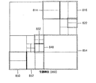
図8Aないし図8Dは、本発明の一実施形態による符号化単位、予測単位及び変換単位の分割形態を示す。 8A to 8D illustrate division forms of a coding unit, a prediction unit, and a transform unit according to an embodiment of the present invention.
図8A及び図8Bは、本発明の一実施形態による符号化単位及び予測単位を示す。 8A and 8B illustrate a coding unit and a prediction unit according to an embodiment of the present invention.
図8Aは、最大符号化単位810を符号化するために、本発明の一実施形態による映像符号化装置100が選択した分割形態を示す。映像符号化装置100は、多様な形態に最大符号化単位810を分割し、符号化した後で多様な分割形態の符号化結果をR−Dコストに基づいて比べて、最適の分割形態を選択する。最大符号化単位810をそのまま符号化することが最適である場合には、図8Aないし図8Dのように、最大符号化単位810を分割せずに最大符号化単位800を符号化してもよい。
FIG. 8A shows a division form selected by the
図8Aを参照すれば、深度0である最大符号化単位810を、深度1以上のサブ符号化単位に分割して符号化する。最大符号化単位810を4つの深度1のサブ符号化単位に分割した後、全部または一部の深度1のサブ符号化単位を、再び深度2のサブ符号化単位に分割する。
Referring to FIG. 8A, a maximum coding unit 810 having a depth of 0 is divided into sub-coding units having a depth of 1 or more and encoded. After dividing the maximum coding unit 810 into four
深度1のサブ符号化単位のうち右側上部に位置しているサブ符号化単位及び左側下部に位置しているサブ符号化単位が、深度2以上のサブ符号化単位に分割された。深度2以上のサブ符号化単位のうち一部は、再び深度3以上のサブ符号化単位に分割されうる。
Of the sub-coding units of
図8Bは、最大符号化単位810に対する予測単位の分割形態を示す。図8Bを参照すれば、最大符号化単位に対する予測単位860は、最大符号化単位810と異なって分割される。言い換えれば、サブ符号化単位それぞれに対する予測単位は、サブ符号化単位より小さい。 FIG. 8B shows a division form of the prediction unit for the maximum coding unit 810. Referring to FIG. 8B, the prediction unit 860 for the maximum coding unit is divided differently from the maximum coding unit 810. In other words, the prediction unit for each sub-coding unit is smaller than the sub-coding unit.
例えば、深度1のサブ符号化単位のうち右側下部に位置しているサブ符号化単位854に対する予測単位は、サブ符号化単位854より小さい。深度2のサブ符号化単位814、8、16、818、828、850、852のうち一部のサブ符号化単位815、816、850、852に対する予測単位は、サブ符号化単位より小さい。
For example, the prediction unit for the
また、深度3のサブ符号化単位822、832、848に対する予測単位は、サブ符号化単位より小さい。予測単位は、それぞれのサブ符号化単位を高さまたは幅方向に半分にした形態であってもよく、高さ及び幅方向に4分した形態であってもよい。
Also, the prediction units for
図8C及び図8Dは、本発明の一実施形態による予測単位及び変換単位を示す。 8C and 8D illustrate prediction units and conversion units according to an embodiment of the present invention.
図8Cは、図8Bに示した最大符号化単位810に対する予測単位の分割形態を示し、図8Dは、最大符号化単位810の変換単位の分割形態を示す。 8C shows a partition form of the prediction unit for the maximum coding unit 810 shown in FIG. 8B, and FIG. 8D shows a partition form of the transform unit of the maximum coding unit 810.
図8Dを参照すれば、変換単位870の分割形態は、予測単位860と異なって設定される。 Referring to FIG. 8D, the division form of the conversion unit 870 is set differently from the prediction unit 860.
例えば、深度1の符号化単位854に対する予測単位が高さを半分にした形態に選択されるとしても、変換単位は、深度1の符号化単位854のサイズと同じサイズに選択されうる。同様に、深度2の符号化単位814、850に対する予測単位が深度2の符号化単位814、850の高さを半分にした形態に選択されるとしても、変換単位は、深度2の符号化単位814、850の元来のサイズと同じサイズに選択されうる。
For example, even if the prediction unit for the
予測単位よりさらに小さなサイズに変換単位が選択されてもよい。例えば、深度2の符号化単位852に対する予測単位が、幅を半分にした形態に選択された場合に、変換単位は、予測単位よりさらに小さなサイズである、高さ及び幅を半分にした形態に選択されうる。
The conversion unit may be selected to have a size smaller than the prediction unit. For example, when the prediction unit for the
図9は、本発明の一実施形態による映像を補間する装置を示す。 FIG. 9 shows an apparatus for interpolating an image according to an embodiment of the present invention.
映像の補間は、低画質の映像を高画質に変換する時に用いられる。インターレース(interlace)映像をプログレッシブ映像に変換する時に用いられてもよく、低画質の映像をアップサンプリングして高画質の映像に変換する時に用いられてもよい。また、図4の映像符号化装置400が映像を符号化する時、動き推定部420及び動き補償部425は、補間された参照フレームを用いてインター予測を行える。参照フレーム495を補間して高画質の映像を生成し、高画質の映像に基づいて動き推定及び補償を行うことで、インター予測の正確度を高めることができる。同様に、映像復号化装置500が映像を復号化する時にも、動き補償部550は、補間された参照フレームを用いて動き補償を行うことで、インター予測の正確度を高めることができる。
Video interpolation is used when converting low-quality video to high quality. It may be used when converting an interlaced video into a progressive video, or may be used when up-sampling a low-quality video into a high-quality video. In addition, when the
図9を参照すれば、本発明の一実施形態による映像補間装置900は、変換部910及び逆変換部920を備える。変換部910は、異なる周波数の複数の基底関数を用いてピクセル値を変換する。変換は、空間ドメインのピクセル値を周波数ドメインの係数に変換するすべての変換であり、前述した離散コサイン変換でありうる。整数ピクセル単位のピクセル値を、複数の基底関数を用いて変換する。ピクセル値は、輝度成分に対するピクセル値であってもよく、彩度(chroma)成分に対するピクセル値であってもよい。基底関数には制限がなく、空間ドメインのピクセル値を周波数ドメインの値に変換するあらゆる変換でありうる。例えば、基底関数は、離散コサイン変換及び逆離散コサイン変換のためのコサイン関数であってもよい。また、サイン基底、多項基底(polynomial basis)などの多様な基底関数が用いられうる。また、離散コサイン変換は、変形離散コサイン変換、ウィンドウを用いた変形離散コサイン変換でありうる。
Referring to FIG. 9, the
逆変換部920は、変換部910で変換に用いられた複数の基底関数の位相を変更し、位相変更された複数の基底関数を用いて変換部910で生成された複数の係数、すなわち、周波数ドメインの値を逆変換する。以下では、変換部910及び逆変換部920が行う変換及び逆変換を、2次元離散コサイン変換及び1次元離散コサイン変換を例として挙げて説明する。
The
<2次元離散コサイン変換及び逆変換>
図10は、本発明の一実施形態による映像補間装置900の2次元補間方法を説明するための図面である。図10を参照すれば、映像補間装置900は、空間ドメインの整数ピクセル単位のピクセル値、すなわち、所定ブロック1000の‘O’位置のピクセル値間を補間して、補間位置である‘X’位置のピクセル値を生成する。‘X’位置のピクセル値は、αx及びαyによって補間位置が定められる分数ピクセル単位のピクセル値である。図10は、所定のブロック1000が4×4である場合を例として説明するが、ブロックのサイズは4×4に限定されず、さらに大きいかまたはさらに小さなサイズのブロックに対して2次元離散コサイン変換及び2次元逆離散コサイン変換を行って分数ピクセル単位のピクセル値を生成できるということは、当業者が容易に分かる。
<Two-dimensional discrete cosine transform and inverse transform>
FIG. 10 is a view for explaining a two-dimensional interpolation method of the
変換部910は、先ず整数ピクセル単位のピクセル値を2次元離散コサイン変換する。2次元離散コサイン変換は、次の数式(1)を計算することで行われる。
The

変換部910が、数式(1)を計算して所定のブロック1000を2次元離散コサイン変換すれば、逆変換部910は、次の数式(4)を計算して変換部910に生成された周波数ドメインの係数を2次元逆離散コサイン変換する。
If the
ところが、前述したように逆変換部910が2次元逆離散コサイン変換を行う時には、位相の変更された基底関数を用いるところ、以下の数式(5)及び(6)のようにW(x)及びW(y)が定義されうる。
However, as described above, when the
数式(5)及び数式(6)を数式(2)及び数式(3)と比較すれば、逆変換部910で用いる基底関数、すなわち、コサイン関数の位相がそれぞれ2αx及び2αyによって変更されたことが分かる。逆変換部910が、数式(5)及び数式(6)の位相変更された複数のコサイン関数に基づいて2次元逆離散コサイン変換を行えば、図10の補間位置、すなわち、“X”位置のピクセル値が生成される。
Comparing Equation (5) and Equation (6) with Equation (2) and Equation (3), the basis function used in the
図11は、本発明の一実施形態による補間領域を説明するための図面である。 FIG. 11 is a diagram for explaining an interpolation area according to an embodiment of the present invention.
図9の変換部910及び逆変換部920が、2次元離散コサイン変換及び2次元逆離散コサイン変換を用いて補間位置のピクセル値を生成する時、補間の対象になるブロック、すなわち、補間領域1110より大きいサイズの領域1120を用いることができる。一般的に補間の正確度は、補間領域1110の境界で低くなる。補間のためには補間位置に隣接しているピクセル値との相関関係を考慮せねばならないが、図9の映像補間装置900は、ブロック400内部のピクセル値を2次元離散コサイン変換し、逆離散コサイン変換するため、ブロック400外部のピクセル値との相関関係が考慮されないからである。
When the
したがって、本発明による映像補間装置900は、補間領域1110及び補間領域1100に隣接している領域を含む大きいサイズのブロック1120に対して補間を行い、動き補償するときには補間領域1110のピクセル値を用いる。
Accordingly, the
<1次元離散コサイン変換及び逆変換>
図12は、本発明の一実施形態による1次元補間の例を示す。図12を参照すれば、映像補間装置900は、空間ドメインの整数ピクセル単位のピクセル値1210及び1220の間を補間して補間位置のピクセル値1200を生成する。αによって補間位置が定められる分数ピクセル単位のピクセル値1200である。図13を参照して詳細に説明する。
<One-dimensional discrete cosine transform and inverse transform>
FIG. 12 shows an example of one-dimensional interpolation according to an embodiment of the present invention. Referring to FIG. 12, the
図13は、本発明の一実施形態による映像補間装置900の1次元補間方法を説明するための図面である。図13を参照すれば、整数ピクセルの二つのピクセル値1210及び1220の間を補間して分数ピクセル単位のピクセル値1200を生成するために、ピクセル値1210及び1220を含む隣接している複数のピクセル値1310及び1320を用いる。言い換えれば、−(M−1)番目からM番目までの2M個のピクセル値を1次元離散コサイン変換し、位相変更された基底関数に基づいて1次元逆離散コサイン変換することで0番目と1番目ピクセルの間を補間できる。図13は、M=6である場合を示したが、Mが必ずしも6であるものではなく、Mは0ではない正の整数でありうるということは当業者ならば容易に分かるであろう。
FIG. 13 is a view for explaining a one-dimensional interpolation method of the
また、図12及び図13は、水平方向のピクセル値間を補間する場合を例として挙げて説明したが、垂直方向のピクセル値間または対角方向のピクセル値間を補間する場合にも、後述する補間方法が同様に適用されるということは当業者ならば容易に分かるであろう。これについては、図18A及び図18Bを参照して後述する。 FIGS. 12 and 13 have been described by taking as an example the case of interpolating between pixel values in the horizontal direction, but also when interpolating between pixel values in the vertical direction or between pixel values in the diagonal direction. Those skilled in the art will readily understand that the interpolation method is equally applicable. This will be described later with reference to FIGS. 18A and 18B.
変換部910は、先ず整数ピクセル単位のピクセル値を1次元離散コサイン変換する。1次元離散コサイン変換は、次の数式(7)を計算することで行われる。
The
変換部910が数式(7)を計算して、ピクセル値1310及び1320を1次元離散コサイン変換すれば、逆変換部910は、次の数式(8)を計算して、変換部910に生成された周波数ドメインの係数を逆変換する。
When the
図14は、本発明のさらに他の実施形態による映像を補間する装置を示す。図14を参照すれば、本発明のさらに他の実施形態による映像補間装置1400は、フィルタ選択部1410及び補間部1420を備える。図9の映像補間装置900は、映像の変換及び位相変更された複数の基底関数に基づいた逆変換を行う装置である。しかし、映像補間装置900にピクセル値が入力される度に、変換及び逆変換を行うためには多量の演算が必要なため、映像処理システムの映像処理速度を低下させる恐れがある。
FIG. 14 shows an apparatus for interpolating an image according to still another embodiment of the present invention. Referring to FIG. 14, a
したがって、映像の変換及び位相変更された複数の基底関数に基づいた逆変換を行うためのフィルタの係数をあらかじめ計算しておき、映像補間装置1400に入力される空間ドメインのピクセル値を予め計算されたフィルタを用いてフィルタリングすれば、周波数ドメインへの変換なしに空間ドメインで速く映像補間を行える。
Therefore, filter coefficients for performing video conversion and inverse conversion based on a plurality of basis functions whose phases have been changed are calculated in advance, and a spatial domain pixel value input to the
フィルタ選択部1410は、補間位置に関する情報を受信して補間に用いられるフィルタを選択する。フィルタは、前述したように異なる周波数の複数の基底関数を用いてピクセル値を変換し、位相変更された基底関数を用いて変換した結果として生成された複数の係数を再び逆変換するためのフィルタである。補間位置によってフィルタの係数が異なるので、補間位置によってフィルタを選択する。
The
図9に関して前述したように、異なる周波数の複数の基底関数を用いてピクセル値を変換した後、補間位置によって逆変換のための基底関数の位相を異なって変更する。次いで、位相変更された基底関数を用いて逆変換すれば、該当の補間位置のピクセル値を補間できる。言い換えれば、整数ピクセル位置のピクセル値に基づいて変換を行い、補間位置によって異なる基底関数に基づいて逆変換を行えば、すべての補間位置に対して分数ピクセル位置のピクセル値を生成できるということを意味する。したがって、図14に示したフィルタ選択部1410は、変換及び異なる基底関数に基づいた逆変換のための複数のフィルタをあらかじめ設定し、補間位置の情報を参照して異なるフィルタのうち一つを選択する。
As described above with reference to FIG. 9, the pixel value is converted using a plurality of basis functions having different frequencies, and then the phase of the basis function for inverse conversion is changed depending on the interpolation position. Next, if inverse transformation is performed using the basis function whose phase has been changed, the pixel value at the corresponding interpolation position can be interpolated. In other words, if conversion is performed based on pixel values at integer pixel positions and inverse conversion is performed based on different basis functions depending on interpolation positions, pixel values at fractional pixel positions can be generated for all interpolation positions. means. Accordingly, the
補間部1420は、フィルタ選択部1410で選択されたフィルタを用いて補間を行う。フィルタ選択部1410に選択されたフィルタに基づいて、整数ピクセル単位の複数のピクセル値をフィルタリングすることで補間を行う。補間結果、所定の補間位置のピクセル値、すなわち、分数ピクセル単位のピクセル値が生成される。2次元フィルタを用いて整数ピクセル単位の複数のピクセル値を含むブロックをフィルタリングすることで、図10に示したように、αx及びαy補間位置の複数のピクセル値が生成される。また、1次元フィルタを用いて、整数ピクセル単位の複数のピクセル値を含む行または列をフィルタリングすることで、図13に示したようなα補間位置のピクセル値が生成される。以下では、2次元フィルタ及び1次元フィルタを用いた補間方法を、図面を参照して詳細に説明する。
The
<2次元フィルタ>
数式(4)に関して前述したように、
<Two-dimensional filter>
As mentioned above with respect to Equation (4),
数式(2)、(3)、(5)、(6)によって、フィルタF(x)及びF(y)は、次の数式(10)及び(11)のように定義される。 The filters F (x) and F (y) are defined as the following mathematical expressions (10) and (11) by the mathematical expressions (2), (3), (5), and (6).
ところが、フィルタF(x)及びF(y)のビット深さを大きくして補間を行えば、さらに正確なフィルタリングが可能である。したがって、本発明の一実施形態は、F(x)及びF(y)の係数に所定の値を乗じて元来の係数より大きい値にし、大きい値の係数を含むフィルタを用いて映像を補間できる。この時、数式(9)を次の数式(12)のように修正できる。 However, more accurate filtering is possible if the bit depth of the filters F (x) and F (y) is increased and interpolation is performed. Accordingly, in one embodiment of the present invention, the coefficients of F (x) and F (y) are multiplied by a predetermined value to be larger than the original coefficient, and the image is interpolated using a filter including a larger coefficient. it can. At this time, the equation (9) can be corrected as the following equation (12).
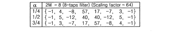
図15は、本発明の一実施形態による2次元補間フィルタを示す。図15を参照すれば、数式(2)によってスケーリングされたフィルタ係数を示す。αxが1/4、1/2及び3/4である時の2次元補間フィルタF’(x)が図示されている。F(x)の係数にスケーリングファクター(scaling factor)213を乗じたF’(x)のフィルタが図示されており、αyが1/4、1/2及び3/4である場合、2次元補間フィルタF’(y)は、F’(x)をトランスポーズして用いられる。
FIG. 15 illustrates a two-dimensional interpolation filter according to an embodiment of the present invention. Referring to FIG. 15, the filter coefficient scaled by Equation (2) is shown. A two-dimensional interpolation filter F ′ (x) when α x is 1/4, 1/2, and 3/4 is shown. A filter of F ′ (x) is shown by multiplying the coefficient of F (x) by a
フィルタ選択部1410が、補間位置に基づいて図14のフィルタのうち一つを選択すれば、補間部1420は、数式(9)または数式(12)を計算して補間位置のピクセル値を生成する。
If the
<1次元フィルタ>
数式(7)による1次元離散コサイン変換を行列式で表現すれば、次の数式(13)の通りである。
<One-dimensional filter>
If the one-dimensional discrete cosine transform according to the equation (7) is expressed by a determinant, the following equation (13) is obtained.
数式(8)による、位相変更された複数の基底関数を用いた1次元逆離散コサイン変換を行列式で表現すれば、次の数式(15)の通りである。 When the one-dimensional inverse discrete cosine transform using the plurality of phase-changed basis functions according to the equation (8) is expressed by a determinant, the following equation (15) is obtained.
2次元補間フィルタと同様に1次元補間フィルタF(α)も、ビット深さを大きくしてフィルタリングの正確度を高めることができる。F(α)の係数に所定の値を乗じ、大きい値の係数を含むフィルタF(α)を用いて映像を補間できる。 Similar to the two-dimensional interpolation filter, the one-dimensional interpolation filter F (α) can also increase the accuracy of filtering by increasing the bit depth. An image can be interpolated using a filter F (α) including a large value coefficient by multiplying the coefficient of F (α) by a predetermined value.
例えば、F(α)にスケーリングのための値として2ScalingBitsを乗じた後、補間を行える。この時、数式(17)の For example, F (α) can be interpolated after multiplying 2 ScalingBits as a value for scaling. At this time, the equation (17)
前述した数式で四捨五入は、フィルタ係数を量子化する方法の一実施形態であるところ、フィルタ係数の量子化方法をさらに一般化すれば、次の数式(19)及び(20)によってフィルタ係数が修正され、最適化される。 Rounding off in the above formula is one embodiment of a method for quantizing the filter coefficient. If the filter coefficient quantization method is further generalized, the filter coefficient is corrected by the following formulas (19) and (20). And optimized.
フィルタ係数が所定のスケーリングファクターによってスケーリングされる場合には、数式(19)による量子化は、次の数式(20)のように修正される。
When the filter coefficient is scaled by a predetermined scaling factor, the quantization according to the equation (19) is corrected as the following equation (20).
図16Aないし図16Fは、本発明の一実施形態による1次元補間フィルタを示す。 16A through 16F illustrate a one-dimensional interpolation filter according to an embodiment of the present invention.
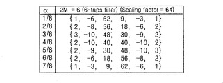
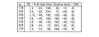
前述した数式(18)で言及したスケーリングされたフィルタが、タップ数及び補間位置によって図示される。図16Aないし図16Fは、それぞれ4−タップフィルタ、6−タップフィルタ、8−タップフィルタ、10−タップフィルタ、12−タップフィルタ及び14−タップフィルタを示す。図16Aないし図16Fはいずれも、フィルタ係数のスケーリングファクターが“256”である場合、すなわち、“ScalingBits”が“8”である場合を示す。 The scaled filter referred to in equation (18) above is illustrated by the number of taps and the interpolation position. 16A to 16F show a 4-tap filter, a 6-tap filter, an 8-tap filter, a 10-tap filter, a 12-tap filter, and a 14-tap filter, respectively. FIGS. 16A to 16F each show a case where the scaling factor of the filter coefficient is “256”, that is, the case where “ScalingBits” is “8”.
図16Aないし図16Fのフィルタの係数は、高周波成分に対する係数を含む。これは、補間及び予測の正確性を高めることはできるが、高周波成分を含むことで映像圧縮の効率を低下させる恐れがある。図9に関して前述したように、補間は、さらに高い効率で映像を圧縮することを目的にする。ところが、補間及び予測の正確性のみ高くなり、圧縮率は低くなれば、補間の本来の目的を果たせない。このために、図16Aないし図16Fの係数をさらに高い圧縮率のために調整できる。 The coefficients of the filters in FIGS. 16A to 16F include coefficients for high frequency components. Although this can improve the accuracy of interpolation and prediction, it may reduce the efficiency of video compression by including a high-frequency component. As described above with respect to FIG. 9, interpolation is aimed at compressing video with higher efficiency. However, if only the accuracy of interpolation and prediction becomes high and the compression rate becomes low, the original purpose of interpolation cannot be achieved. For this reason, the coefficients of FIGS. 16A-16F can be adjusted for higher compression ratios.
例えば、フィルタ係数全体の絶対値のサイズを小さくし、フィルタの中央に位置している係数にさらに大きい加重値を乗じることができる。図16Bの1/2補間位置のピクセル値を生成するための6−タップフィルタを例として挙げれば、{11,−43,160,160,−43,11,}で“11”、“−43”及び“160”の絶対値のサイズが小さくなるように係数を調整し、中央に位置している“160”のみに加重値を乗じることでフィルタ係数を調整できる。 For example, the size of the absolute value of the entire filter coefficient can be reduced, and a coefficient positioned at the center of the filter can be multiplied by a larger weight value. Taking the 6-tap filter for generating the pixel value at the ½ interpolation position in FIG. 16B as an example, {11, −43, 160, 160, −43, 11, and} are “11”, “−43”. The filter coefficient can be adjusted by adjusting the coefficient so that the absolute value size of “160” and “160” is small and multiplying only “160” located at the center by the weight value.
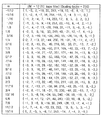
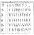
図17Aないし図17Yは、本発明の一実施形態による最適化された1次元補間フィルタを示す。 17A-17Y illustrate an optimized one-dimensional interpolation filter according to an embodiment of the present invention.
図16Aないし図16Fに示したフィルタをハードウェア具現に好適に調整することもできる。コンピュータで数式(17)または(18)の計算を行う時、算術計算、すなわち、2進数のビットシフト及び加算が最小化されるようにフィルタ係数を最適化できる。 The filters shown in FIGS. 16A to 16F can be suitably adjusted for hardware implementation. When computing the equation (17) or (18) with a computer, the filter coefficients can be optimized so that arithmetic calculations, ie, bit shifts and additions of binary numbers, are minimized.
図17A及び図17Bを参照すれば、それぞれのフィルタに対して補間のためのフィルタリングを行う時、必要な計算量が“adding”及び“shift”と図示されている。図17Aないし図17Mのフィルタは、該当補間位置で“adding”及び“shift”が最小化するように最適化された係数を含む。 Referring to FIGS. 17A and 17B, when performing filtering for interpolation on the respective filters, the necessary calculation amounts are illustrated as “adding” and “shift”. The filters of FIGS. 17A to 17M include coefficients optimized to minimize “adding” and “shift” at the corresponding interpolation position.
図17A及び図17Bは、8ビットoffsetによってスケーリングされた1/4ピクセルの正確度で映像を補間するための、最適化された6タップフィルタ及び12タップフィルタを示す。図17C、図17D及び図17Eは、8ビットoffsetによってスケーリングされた1/4ピクセルの正確度で映像を補間するための8タップフィルタを示す。図17C、図17D及び図17Eのフィルタは、フィルタ係数の最適化如何及び/または最適化方法によって区分される。図17F及び図17Gは、6ビットoffsetによってスケーリングされた1/4ピクセルの正確度で補間するための8タップフィルタを示す。図17F及び図17Gのフィルタは、フィルタ係数の最適化方法によって区分される。 FIGS. 17A and 17B show optimized 6-tap and 12-tap filters for interpolating video with 1/4 pixel accuracy scaled by 8-bit offset. FIGS. 17C, 17D, and 17E illustrate an 8-tap filter for interpolating video with 1/4 pixel accuracy scaled by an 8-bit offset. The filters of FIGS. 17C, 17D, and 17E are classified according to the optimization of the filter coefficient and / or the optimization method. FIGS. 17F and 17G show an 8-tap filter for interpolating with 1/4 pixel accuracy scaled by a 6-bit offset. The filters of FIGS. 17F and 17G are classified according to the filter coefficient optimization method.
図17Hは、6ビットoffsetによってスケーリングされた1/8ピクセルの正確度で映像を補間するための、最適化された6タップフィルタを示す。図17Iは、8ビットoffsetによってスケーリングされた1/8ピクセルの正確度で映像を補間するための、最適化された6タップフィルタを示す。 FIG. 17H shows an optimized 6-tap filter for interpolating video with 1/8 pixel accuracy scaled by 6-bit offset. FIG. 17I shows an optimized 6-tap filter for interpolating a video with 1/8 pixel accuracy scaled by an 8-bit offset.
図17J及び図17Kは、5ビットoffsetによってスケーリングされた1/8ピクセルの正確度で映像を補間するための、最適化された4タップフィルタを示す。図17J及び図17Kのフィルタは、フィルタ係数の最適化方法によって区分される。図17L及び図17Mは、8ビットoffsetによってスケーリングされた1/8ピクセルの正確度で映像を補間するための最適化された4タップフィルタを示す。図17L及び図17Mのフィルタも、フィルタ係数の最適化方法によって区分される。 FIGS. 17J and 17K show an optimized 4-tap filter for interpolating video with 1/8 pixel accuracy scaled by a 5-bit offset. The filters of FIGS. 17J and 17K are classified according to the filter coefficient optimization method. FIGS. 17L and 17M show an optimized 4-tap filter for interpolating video with 1/8 pixel accuracy scaled by an 8-bit offset. The filters of FIGS. 17L and 17M are also classified by the filter coefficient optimization method.
図17N及び図17Yは、8ビットoffsetによってスケーリングされた1/8ピクセルの正確度で映像を補間するための、最適化された4タップフィルタ、6タップフィルタ、8タップフィルタ、10タップフィルタ及び12タップフィルタを示す。図17Aないし図17Mに図示されたフィルタに比べれば、フィルタ係数のうち一部の値が異なるだけであり、1/8補間位置を補間するためのフィルタの係数と7/8補間位置を補間するためのフィルタの係数とが互いに対称であり、2/8補間位置を補間するためのフィルタの係数と6/8補間位置を補間するためのフィルタの係数とが互いに対称であり、3/8補間位置を補間するためのフィルタの係数と5/8補間位置を補間するためのフィルタの係数とが互いに対称であるという点は同一である。 17N and 17Y show optimized 4-tap filters, 6-tap filters, 8-tap filters, 10-tap filters, and 12 for interpolating video with 1/8 pixel accuracy scaled by 8-bit offset. Indicates a tap filter. Compared with the filters shown in FIGS. 17A to 17M, only some of the filter coefficients are different, and the filter coefficients for interpolating the 1/8 interpolation position and the 7/8 interpolation position are interpolated. And the filter coefficient for interpolating the 2/8 interpolation position and the filter coefficient for interpolating the 6/8 interpolation position are symmetric with each other. The filter coefficient for interpolating the position and the filter coefficient for interpolating the 5/8 interpolation position are the same as each other.
図23Aないし図23Eは、本発明の一実施形態による1次元補間フィルタのスケーリング及び四捨五入方法を示す。 23A to 23E illustrate a scaling and rounding method for a one-dimensional interpolation filter according to an embodiment of the present invention.
前述したように、補間フィルタリング方法は離散コサイン変換及び逆変換を用いるため、1次元補間フィルタは、絶対値が1以下のフィルタ係数を含む。したがって、数式(12)に関して前述したように、2ScalingBitsほど乗じてフィルタ係数をスケーリングし、スケーリングされた係数を四捨五入して整数にした後、補間に用いる。 As described above, since the interpolation filtering method uses discrete cosine transform and inverse transform, the one-dimensional interpolation filter includes a filter coefficient having an absolute value of 1 or less. Therefore, as described above with respect to Equation (12), the filter coefficient is scaled by multiplying by 2 ScalingBits , and the scaled coefficient is rounded to an integer before being used for interpolation.
図23Aは、2ScalingBitsによってスケーリングされたフィルタ係数を示す。12タップフィルタである場合を図示し、スケーリングされただけであり、まだ整数に四捨五入されていない係数を含む。 FIG. 23A shows the filter coefficients scaled by 2 ScalingBits . The case of a 12 tap filter is illustrated, including coefficients that have only been scaled and have not yet been rounded to an integer.
図23Aのスケーリングされたフィルタ係数を小数点の第1桁で四捨五入して整数にすれば、図23Bに示した通りである。図23Bの補間フィルタを検討すれば、スケーリング後に四捨五入されたフィルタ係数の和が256にならないフィルタがある。1/8補間位置のピクセル値を補間するためのフィルタ、3/8補間位置のピクセル値を補間するためのフィルタ、5/8補間位置のピクセル値を補間するためのフィルタ及び7/8補間位置のピクセル値を補間するためのフィルタのフィルタ係数をいずれも加えれば、256にならない。8ビットScalingBitsによってスケーリングされたフィルタのフィルタ係数の和は、256にならねばならないのにもかかわらず、フィルタ係数を四捨五入する過程で誤差が発生する。 If the scaled filter coefficient of FIG. 23A is rounded off to the first decimal place to be an integer, it is as shown in FIG. 23B. Considering the interpolation filter in FIG. 23B, there is a filter in which the sum of filter coefficients rounded off after scaling does not become 256. Filter for interpolating pixel values at 1/8 interpolation position, filter for interpolating pixel values at 3/8 interpolation position, filter for interpolating pixel values at 5/8 interpolation position, and 7/8 interpolation position If any of the filter coefficients of the filter for interpolating the pixel values of the above are added, it will not be 256. Although the sum of the filter coefficients of the filter scaled by 8-bit ScalingBits must be 256, an error occurs in the process of rounding the filter coefficients.
フィルタ係数の和が一定でないのは、補間位置によってピクセル値のサイズが異なることを意味し、これを解決するために、フィルタ係数を調整して正規化したフィルタを生成できる。図23Bのフィルタのフィルタ係数を調整して生成された正規化されたフィルタは、図23Cに図示される。 The fact that the sum of the filter coefficients is not constant means that the size of the pixel value varies depending on the interpolation position. In order to solve this problem, a normalized filter can be generated by adjusting the filter coefficient. A normalized filter generated by adjusting the filter coefficients of the filter of FIG. 23B is illustrated in FIG. 23C.
図23Bと図23Cとを比較すれば、1/8補間位置のピクセル値を補間するためのフィルタ、3/8補間位置のピクセル値を補間するためのフィルタ、5/8補間位置のピクセル値を補間するためのフィルタ及び7/8補間位置のピクセル値を補間するためのフィルタのフィルタ係数のうち一部を調整して、全体フィルタ係数の和が256に正規化されたことが分かる。 Comparing FIG. 23B and FIG. 23C, a filter for interpolating the pixel value at the 1/8 interpolation position, a filter for interpolating the pixel value at the 3/8 interpolation position, and a pixel value at the 5/8 interpolation position. It can be seen that the sum of the overall filter coefficients is normalized to 256 by adjusting a part of the filter coefficients of the filter for interpolation and the filter for interpolating the pixel value at the 7/8 interpolation position.
図23D及び図23Eは、8タップフィルタに対するスケーリングされたフィルタ及び正規化されたフィルタを示す。2ScalingBitsによってスケーリングされた8タップフィルタが図23Dと同一である時、図23Dに図示された8タップフィルタを小数点の第1桁で四捨五入した後、全体フィルタ係数の和が256になるように正規化したフィルタは、図23Eに示した通りである。図23Eに示したところによれば、一部のフィルタ係数が図23Dに示した8タップフィルタのフィルタ係数を四捨五入した値と異なるということが分かる。全体フィルタ係数の和が256になるように一部のフィルタ係数を調整したからである。 23D and 23E show a scaled filter and a normalized filter for an 8-tap filter. 2 When the 8-tap filter scaled by ScalingBits is the same as that shown in FIG. 23D, the 8-tap filter shown in FIG. 23D is normalized so that the sum of the whole filter coefficients becomes 256 after rounding off to the first decimal place. The converted filter is as shown in FIG. 23E. As shown in FIG. 23E, it can be seen that some of the filter coefficients are different from the values obtained by rounding off the filter coefficients of the 8-tap filter shown in FIG. 23D. This is because some filter coefficients are adjusted so that the sum of the total filter coefficients becomes 256.
図23B及び図23Cに示したように、スケーリング及び/または四捨五入によって少なくとも一つのフィルタ係数が異なるところ、図16Aないし図16Fまたは図17Aないし図17Yに示したフィルタで、少なくとも一つのフィルタ係数が所定の誤差範囲(例えば、±1または±2)内で異なる1次元補間フィルタも本発明の範囲に含まれるということは、当業者ならば容易に分かるであろう。 As shown in FIGS. 23B and 23C, at least one filter coefficient differs depending on scaling and / or rounding. In the filters shown in FIGS. 16A to 16F or 17A to 17Y, at least one filter coefficient is predetermined. Those skilled in the art will readily understand that one-dimensional interpolation filters that differ within a certain error range (eg, ± 1 or ± 2) are also included in the scope of the present invention.
フィルタ選択部1410が、補間位置に基づいて、図16Aないし図16Fまたは図17Aないし図17Yのフィルタのうち一つを選択すれば、補間部1420は、数式(17)または(18)を計算して補間位置のピクセル値を生成する。フィルタ選択部1410がフィルタを選択するに当って、補間位置以外に他の要素、例えば、インター予測の方向、ループフィルタタイプ、ブロック内のピクセル位置などの要素も考慮できる。補間されるブロックのサイズによって異なるサイズ(すなわち、異なるタップ)のフィルタを選択してもよく、補間のためのフィルタリングの方向によって、異なるサイズのフィルタを選択してもよい。例えば、補間されるブロックが大きければ、サイズの大きいフィルタを選択してもよく、垂直方向に補間する場合には、メモリ接近を最小化するために、サイズの小さなフィルタのフィルタを選択してもよい。
If the
実施形態によってフィルタの選択に関する情報が別途に符号化される。例えば、映像補間が映像の符号化過程で行われる場合には、いかなるフィルタを用いて補間したかを復号化する側で知っていて初めて、符号化過程で用いられたフィルタと同じフィルタを用いて映像を補間し、復号化できる。このために、補間に用いられたフィルタを特定できる情報が映像とともに符号化されてもよい。但し、フィルタの選択が以前の符号化結果、すなわち、コンテキストに基づいて行われる場合には、フィルタ選択に関する情報を別途に符号化する必要がない。 According to the embodiment, information related to filter selection is encoded separately. For example, when video interpolation is performed in the video encoding process, the same filter as that used in the encoding process is used only when the decoding side knows what filter was used for the interpolation. Interpolate and decode video. For this purpose, information that can specify the filter used for the interpolation may be encoded together with the video. However, when filter selection is performed based on the previous encoding result, that is, context, there is no need to separately encode information relating to filter selection.
補間結果として生成されたピクセル値がピクセル値の最小値より小さいか、または最大値より大きければ、最小値または最大値に調整する。例えば、補間結果として生成されたピクセル値が最小値である“0”より小さければ“0”に調整し、最大値である“255”より大きければ“255”に調整する。 If the pixel value generated as an interpolation result is smaller than the minimum pixel value or larger than the maximum value, the pixel value is adjusted to the minimum value or the maximum value. For example, if the pixel value generated as an interpolation result is smaller than “0” which is the minimum value, the pixel value is adjusted to “0”, and if larger than “255” which is the maximum value, the pixel value is adjusted to “255”.
映像の符号化過程でインター予測をさらに正確に行うために補間を行う場合には、補間フィルタを特定するための情報も共に符号化されうる。言い換えれば、フィルタ選択部1410がいかなるフィルタを選択したかを示す情報を、映像パラメータとして映像と共に符号化できる。補間フィルタの選択は、符号化単位またはスライスまたはピクチャーごとに異なるので、フィルタ選択に関する情報も、符号化単位またはスライス単位またはピクチャー単位で、映像と共に符号化されうる。しかし、フィルタ選択が暗黙的なルールによってなされる場合には、フィルタ選択に関する情報が映像と共に符号化されなくてもよい。
When interpolation is performed in order to perform inter prediction more accurately in the video encoding process, information for specifying an interpolation filter can be encoded together. In other words, information indicating what filter the
補間部1420が補間を行う多様な実施形態について、図18A、図18B及び19を参照して詳細に説明する。
Various embodiments in which the
図18A及び図18Bは、本発明の一実施形態による1次元補間フィルタを用いた多様な方向のピクセル値を補間する方法を説明する。図18A及び図18Bを参照すれば、1次元来のピクセル値を1次元離散コサイン変換し、位相変更された複数の基底関数を用いて1次元逆離散コサイン変換するための1次元補間フィルタを用いて、多様な方向の補間位置のピクセル値を生成できる。 18A and 18B illustrate a method of interpolating pixel values in various directions using a one-dimensional interpolation filter according to an embodiment of the present invention. 18A and 18B, a one-dimensional interpolation filter for performing one-dimensional discrete cosine transform on a one-dimensional pixel value and performing one-dimensional inverse discrete cosine transform using a plurality of phase-changed basis functions is used. Thus, pixel values of interpolation positions in various directions can be generated.
図18Aを参照すれば、垂直方向に隣接しているP01802とP11804との間を補間して、垂直方向の補間位置αのピクセル値P(α)を生成できる。図13に比べれば、水平方向に配列されたピクセル値1310及び1320の代りに、垂直方向に配列されたピクセル値1810及び1820を用いて補間を行うという点のみ異なるだけであり、数式(13)ないし(18)に関して前述した補間方法がそのまま適用されうる。
Referring to FIG. 18A, the pixel value P (α) of the interpolation position α in the vertical direction can be generated by interpolating between
図18Bの実施形態も、図18Aの実施形態と同様に、水平方向に配列されたピクセル値1310及び1320の代りに、対角方向に配列されたピクセル値1840及び1850を用いるという点のみ異なるだけであり、隣接している2つのピクセル値1832及び1834の間を補間して補間位置αのピクセル値1830を生成する方法は、数式(13)ないし(18)に関して前述した補間方法と同一である。
The embodiment of FIG. 18B differs from the embodiment of FIG. 18A only in that it uses
図19Aは、本発明の一実施形態による2次元補間方法を説明するための図面である。図19Aを参照すれば、整数ピクセル単位のピクセル値1900ないし1906に基づいて、分数ピクセル単位のピクセル値1910ないし1950が生成される。
先ず、映像補間装置1400のフィルタ選択部1410は、整数ピクセル単位のピクセル値1900ないし1906の間に存在する分数ピクセル単位のピクセル値1910、1920、1930及び1940を生成するための1次元補間フィルタを選択する。図14に関して前述したように、補間位置によって異なるフィルタが選択される。例えば、上部に位置している二つのピクセル値1900及び1902の間のピクセル値1910を補間するためのフィルタは、分数ピクセル単位のピクセル値1912、1914及び1916それぞれに対して異なって選択されうる。1/2ピクセル単位のピクセル値1914を生成するためのフィルタと、1/4ピクセル単位のピクセル値1912及び1916とを生成するためのフィルタとが異なる。また、同じ1/4ピクセル単位のピクセル値1912及び1916も異なるフィルタに基づいて生成される。図14に関して前述したように、それぞれの補間位置ごとに逆変換のための基底関数の位相変更程度が異なるので、補間のために選択されるフィルタも異なる。
FIG. 19A is a view for explaining a two-dimensional interpolation method according to an embodiment of the present invention. Referring to FIG. 19A,
First, the
同様に、整数ピクセル単位のピクセル値1900ないし1906の間の異なる分数ピクセル単位のピクセル値1920、1930及び1940も、補間位置によって異なって選択された1次元補間フィルタに基づいて生成される。
Similarly,
フィルタ選択部1410が、整数ピクセル単位のピクセル値1900ないし1906の間の分数ピクセル単位のピクセル値1910、1920、1930及び1940を生成するためのフィルタを選択すれば、補間部1420は、選択されたフィルタに基づいてそれぞれの補間位置における分数ピクセル単位のピクセル値を生成する。本発明によれば、それぞれの補間位置のピクセル値を生成するためのフィルタがあらかじめ計算されているので、すべての補間位置のピクセル値を整数ピクセル単位のピクセル値に基づいて生成できる。
If the
言い換えれば、1/4ピクセル単位のピクセル値1912及び1916は、整数ピクセル単位のピクセル値1900及び1920に基づいて直接生成され、1/2ピクセル単位のピクセル値1914を先ず計算し、整数ピクセル単位のピクセル値1900及び1902及び1/2ピクセル単位のピクセル値1914に基づいて1/4ピクセル単位のピクセル値1912及び1916を生成する必要がない。映像補間を、ピクセル単位が低くなるにつれて順次に行う必要がないため、速い速度で映像補間を行える。
In other words, the
しかし、本発明の他の実施形態によれば、補間位置によって本発明による補間方法と従来技術による補間方法とを結合してもよい。例えば、1/2ピクセル単位及び1/4ピクセル単位のピクセル値は、本発明による補間フィルタを用いて、整数ピクセル単位のピクセル値1900及び1920から直接生成し、1/8ピクセル単位のピクセル値は、1/4ピクセル単位のピクセル値に、従来技術による線形補間フィルタを適用して生成してもよい。また、1/2ピクセル単位のピクセル値のみ、本発明による補間フィルタを用いて整数ピクセル単位のピクセル値1900及び1920から直接生成し、1/4ピクセル単位のピクセル値は、1/2ピクセル単位のピクセル値に、従来技術による線形補間フィルタを適用して生成し、1/8ピクセル単位のピクセル値は、1/4ピクセル単位のピクセル値に、従来技術による線形補間フィルタを適用して生成してもよい。
However, according to another embodiment of the present invention, the interpolation method according to the present invention and the interpolation method according to the prior art may be combined according to the interpolation position. For example, pixel values in 1/2 pixel units and 1/4 pixel units are generated directly from
補間結果、整数ピクセル単位のピクセル値1900ないし1906の間の分数ピクセル単位のピクセル値1910、1920、1930及び1940がいずれも生成されれば、フィルタ選択部1410は、分数ピクセル単位のピクセル値1910、1920、1930及び1940の間を補間するための1次元補間フィルタを再び選択する。整数ピクセル単位のピクセル値1900ないし1906の間を補間するために、フィルタを選択する時と同様に、補間位置によって異なるフィルタを選択する。
If pixel values 1910, 1920, 1930, and 1940 in fractional pixels between
補間部1420は、フィルタ選択部1410で選択されたフィルタによって、補間位置それぞれに対応する分数ピクセル単位のピクセル値1950を生成する。分数ピクセル単位のピクセル値1910、1920、1930及び1940の間の他の分数ピクセル単位のピクセル値1950が生成される。
The
図19Bは、本発明の一実施形態による1次元補間フィルタを用いた2次元補間方法を説明するための図面である。図19Bを参照すれば、1次元補間フィルタを用いて垂直方向補間及び水平方向補間を繰り返して行うことで、2次元補間位置のピクセル値を生成できる。 FIG. 19B is a diagram illustrating a two-dimensional interpolation method using a one-dimensional interpolation filter according to an embodiment of the present invention. Referring to FIG. 19B, a pixel value at a two-dimensional interpolation position can be generated by repeatedly performing vertical direction interpolation and horizontal direction interpolation using a one-dimensional interpolation filter.
整数ピクセル単位のピクセル値REF(i,j)1960及びREF(i+1,j)1964の間を水平方向に補間してTemp(i,j)を生成する。また、REF(i,j+1)1962及びREF(i+1,j+1)1966の間を水平方向に補間してTemp(i,j+1)を生成する。次いで、Temp(i,j)及びTemp(i,j+1)の間を垂直方向に補間して2次元補間位置のP(i,j)を生成する。
Temp (i, j) is generated by horizontally interpolating between
1次元補間フィルタは、前述した1次元離散コサイン変換及び位相変更された複数の基底関数に基づいた1次元逆離散コサイン変換のためのフィルタでありうる。また、1次元補間フィルタは、数式(17)に関して前述したスケーリングされたフィルタでありうるが、スケーリングされたフィルタに基づいて水平及び垂直方向補間を行う場合、次の数式(21)を計算することで補間を行える。 The one-dimensional interpolation filter may be a filter for the one-dimensional inverse discrete cosine transform based on the above-described one-dimensional discrete cosine transform and a plurality of phase-changed basis functions. Also, the one-dimensional interpolation filter may be the scaled filter described above with respect to Equation (17), but when performing horizontal and vertical interpolation based on the scaled filter, calculate the following Equation (21): Can be used for interpolation.
水平方向の補間及び垂直方向の補間を行う時に、水平補間後にStageBits1によって最初のビットシフティングが行われ、垂直補間が行われた後でStageBits2が行われる。(すなわち、TotalBits=StageBits1+StageBits2)Stage1Bits1が0に設定されるならば、最初のビットシフティングは行われない。 When horizontal interpolation and vertical interpolation are performed, first bit shifting is performed by StageBits1 after horizontal interpolation, and StageBits2 is performed after vertical interpolation is performed. (Ie, TotalBits = StageBits1 + StageBits2) If Stage1Bits1 is set to 0, the first bit shifting is not performed.
したがって、F’l(αy)のスケーリングファクターが“2bit1”であり、F’l(αx)のスケーリングファクターが“2bit2”である時、数式(21)の“bits”は“bits=bit1+bit2”である。また、TotalBits=‘bit1’+‘bit2’である。 Therefore, 'a l (α y) scaling factor of "2 bit1", F' F when scaling factor of l (α x) is "2 bit2", formula (21) "bits" are "bits = Bit1 + bit2 ". Also, TotalBits = 'bit1' + 'bit2'.
図19Cは、本発明のさらに他の実施形態による1次元補間フィルタを用いた2次元補間方法を説明するための図面である。図19Cを参照すれば、1次元補間フィルタを用いて垂直方向補間及び水平方向補間を繰り返して行うことで2次元補間位置のピクセル値を生成できる。 FIG. 19C is a view for explaining a two-dimensional interpolation method using a one-dimensional interpolation filter according to another embodiment of the present invention. Referring to FIG. 19C, a pixel value at a two-dimensional interpolation position can be generated by repeatedly performing vertical direction interpolation and horizontal direction interpolation using a one-dimensional interpolation filter.
整数ピクセル単位のピクセル値REF(i,j)1960及びREF(i,j+1)1962の間を垂直方向に補間してTemp(i,j)を生成する。また、REF(i,j+1)1964及びREF(i+1,j+1)1966の間を垂直方向に補間してTemp(i+1,j)を生成する。次いで、Temp(i,j)及びTemp(i+1,j)の間を水平方向に補間して2次元補間位置のP(i,j)を生成する。スケーリングされたフィルタに基づいて水平及び垂直方向補間を行う場合、次の数式(22)を計算することで補間を行える。
Temp (i, j) is generated by vertically interpolating between
変換は、2次元離散コサイン変換または1次元離散コサイン変換であり、これについて変換部910、数式(1)、(2)、(3)及び7に関して前述した。
The transformation is a two-dimensional discrete cosine transformation or a one-dimensional discrete cosine transformation, which has been described above with respect to the
段階2020で、映像補間装置900は、段階2010の変換に用いられた複数の基底関数の位相を変更する。αx及びαyによって定められる2次元補間位置またはαにより定められる1次元補間位置によって、変換に用いられた複数の基底関数の位相を変更する。
In
段階2030で、映像補間装置900は、段階2020で位相が変更された複数の基底関数を用いて、段階2010の変換結果として生成された複数の係数を逆変換する。段階2010で、変換結果として生成された複数の係数を逆変換して補間位置のピクセル値を生成する。
In
段階2010の変換が2次元離散コサイン変換であったならば、段階2030で映像補間装置900は、位相変更された複数のコサイン関数を用いて、複数の離散コサイン係数を2次元逆離散コサイン変換して2次元補間位置のピクセル値を生成する。
If the transformation in
段階2010の変換が、ピクセル値の行または列に対する1次元離散コサイン変換であれば、段階2030で映像補間装置900は、位相変更された複数のコサイン関数を用いて複数の離散コサイン係数を1次元逆離散コサイン変換して、1次元補間位置のピクセル値を生成する。
If the transformation in
位相変更された複数の基底関数及びこれに基づく逆変換は、逆変換部920、数式(4)、(5)、(6)及び(8)に関して前述した。
The plurality of basis functions whose phases are changed and the inverse transformation based thereon are described above with respect to the
図21は、本発明の他の実施形態による映像を補間する方法を説明するためのフローチャートである。図21を参照すれば、段階2110で、本発明の一実施形態による映像補間装置1400は、変換及び位相変更された複数の基底関数に基づいた逆変換のためのフィルタを、補間位置に基づいて選択する。補間位置に基づく離散コサイン変換、及び位相変更された複数のコサイン関数に基づく逆離散コサイン変換のためのフィルタを選択する。補間されるピクセル値が所定のブロックである場合には、2次元離散コサイン変換及び2次元逆離散コサイン変換のためのフィルタをαx及びαyに基づいて選択し、補間されるピクセル値が行または列である場合には、1次元離散コサイン変換及び1次元逆離散コサイン変換のためのフィルタをαに基づいて選択する。図15または図16Aないし図16Fまたは図17に示したフィルタのうち一つを、補間位置に基づいて選択できる。補間位置はもとより他の要素を考慮してフィルタのサイズを選択できるということは、フィルタ選択部1410及び図17に関して前述した。
FIG. 21 is a flowchart for explaining a method of interpolating an image according to another embodiment of the present invention. Referring to FIG. 21, in
段階2120で、映像補間装置1400は、段階2110で選択されたフィルタに基づいて補間を行う。段階2110で補間位置に基づいて選択されたフィルタを用いて、空間ドメインのピクセル値をフィルタリングすることで、2次元補間位置のピクセル値または1次元補間位置のピクセル値を生成する。フィルタを用いた補間は、数式(9)ないし(19)に関して前述した。
In
図22は、本発明のさらに他の実施形態による映像を補間する方法を説明するためのフローチャートである。図22を参照すれば、段階2210で、映像補間装置1400は、整数ピクセル単位のピクセル値1900ないし1906の間を補間するためのフィルタを、補間位置によって異なって選択する。本発明の一実施形態による映像補間方法によれば、分数ピクセル単位のピクセル値1910、1920、1930及び1940が、整数ピクセル単位のピクセル値1900ないし1906から直接生成される。したがって、映像補間装置1400は、補間位置それぞれに対応する補間フィルタを段階2210で選択する。
FIG. 22 is a flowchart illustrating a method for interpolating an image according to still another embodiment of the present invention. Referring to FIG. 22, in
段階2220で、映像補間装置1400は、段階2210で補間位置によって異なって選択されたフィルタに基づいて整数ピクセル単位のピクセル値1900ないし1906の間を補間して、少なくとも一つの分数ピクセル単位のピクセル値1910、1920、1930及び1940を生成する。
In
段階2230で、映像補間装置1400は、段階2220で生成された分数ピクセル単位のピクセル値1910、1920、1930及び1940の間を補間するためのフィルタを、補間位置によって異なって選択する。図19の分数ピクセル単位のピクセル値1910、1920、1930及び1940の間の他の分数ピクセル単位のピクセル値1950を生成するためのフィルタを、補間位置によって異なって選択する。
In
段階2240で、映像補間装置1400は、段階2230で選択されたフィルタに基づいて分数ピクセル単位のピクセル値1910、1920、1930及び1940を補間して、他の分数ピクセル単位のピクセル値1950を生成する。
In
以上のように、本発明はたとえ限定された実施形態及び図面によって説明されたにしても、本発明が前記の実施形態に限定されるものではなく、これは当業者ならば、これらの記載より多様な修正及び変形が可能であろう。したがって、本発明の思想は、特許請求の範囲のみによって把握されねばならず、これと均等または等価的な変形はいずれも本発明の思想の範ちゅうに属するといえる。また、本発明によるシステムは、コンピュータで読み取り可能な記録媒体にコンピュータで読み取り可能なコードとして具現できる。 As described above, even though the present invention has been described with reference to the limited embodiments and drawings, the present invention is not limited to the above-described embodiments, and those skilled in the art will understand from these descriptions. Various modifications and variations will be possible. Therefore, the idea of the present invention must be grasped only by the scope of the claims, and any equivalent or equivalent modifications can be said to belong to the category of the idea of the present invention. In addition, the system according to the present invention can be embodied as a computer readable code on a computer readable recording medium.
例えば、本発明の例示的な実施形態による映像符号化装置、映像復号化装置、映像符号化部、映像復号化部及び映像補間装置は、図1、2、4、5、9及び14に示したような装置それぞれのユニットにカップリングされたバス、前記バスに結合された少なくとも一つのプロセッサを備える。また、命令、受信されたメッセージまたは生成されたメッセージを保存するために前記バスに結合されて、前述したような命令を行うための少なくとも一つのプロセッサにカップリングされたメモリを備える。 For example, a video encoding device, a video decoding device, a video encoding unit, a video decoding unit, and a video interpolation device according to exemplary embodiments of the present invention are shown in FIGS. A bus coupled to each unit of the device, and at least one processor coupled to the bus. There is also a memory coupled to the bus for storing instructions, received messages or generated messages and coupled to at least one processor for executing instructions as described above.
また、コンピュータで読み取り可能な記録媒体は、コンピュータシステムによって読み取られるデータが保存されるすべての記録装置を含む。記録媒体の例としては、ROM、RAM、CD−ROM、磁気テープ、フロッピー(登録商標)ディスク、光データ保存装置などを含む。また、コンピュータで読み取り可能な記録媒体は、ネットワークに連結されたコンピュータシステムに分散されて、分散方式でコンピュータで読み取れるコードが保存されて実行される。 The computer-readable recording medium includes all recording devices in which data to be read by a computer system is stored. Examples of the recording medium include ROM, RAM, CD-ROM, magnetic tape, floppy (registered trademark) disk, optical data storage device, and the like. The computer-readable recording medium is distributed in a computer system connected to a network, and a computer-readable code is stored and executed in a distributed manner.
以下、本願により教示される手段を例示的に列挙する。 Hereinafter, the means taught by the present application will be exemplified.
(付記1)
映像を補間する方法において、
複数の異なるフィルタのうち、整数ピクセル単位のピクセル値間を補間するための第1フィルタを補間位置によって選択する段階と、
前記選択された第1フィルタを用いて、前記整数ピクセル単位のピクセル値間を補間して、少なくとも一つの分数ピクセル単位のピクセル値を生成する段階と、を含むことを特徴とする映像補間方法。
(Appendix 1)
In the method of interpolating video,
Selecting a first filter for interpolating between pixel values in integer pixel units among a plurality of different filters according to an interpolation position;
Interpolating between pixel values in integer pixel units using the selected first filter to generate at least one fractional pixel unit pixel value.
(付記2)
前記複数の異なるフィルタのうち、前記生成された少なくとも一つの分数ピクセル単位のピクセル値間を補間するための第2フィルタを補間位置によって選択する段階と、
前記第2フィルタを用いて、前記少なくとも一つの分数ピクセル単位のピクセル値間を補間する段階と、をさらに含むことを特徴とする付記1に記載の映像補間方法。
(Appendix 2)
Selecting a second filter for interpolating between the generated at least one fractional pixel unit pixel value among the plurality of different filters according to an interpolation position;
The method of
(付記3)
前記第1フィルタは、
異なる周波数の複数の基底関数を用いて、前記整数ピクセル単位のピクセル値を変換し、位相変更された複数の基底関数を用いて、前記変換結果として生成された複数の係数を逆変換するための空間ドメインのフィルタであることを特徴とする付記2に記載の映像補間方法。
(Appendix 3)
The first filter is:
Converting the pixel value of the integer pixel unit using a plurality of basis functions having different frequencies, and inversely converting the plurality of coefficients generated as the conversion result using the plurality of basis functions whose phases are changed. The video interpolation method according to
(付記4)
前記第2フィルタは、
異なる周波数の複数の基底関数を用いて、前記生成された少なくとも一つの分数ピクセル単位のピクセル値を変換し、位相変更された複数の基底関数を用いて、前記変換結果として生成された複数の係数を逆変換するための空間ドメインのフィルタであることを特徴とする付記3に記載の映像補間方法。
(Appendix 4)
The second filter is
Converting the generated pixel value of at least one fractional pixel unit using a plurality of basis functions of different frequencies, and using a plurality of basis functions whose phases are changed, a plurality of coefficients generated as the
(付記5)
映像を補間する装置において、
複数の異なるフィルタのうち、整数ピクセル単位のピクセル値間を補間するための第1フィルタを補間位置によって選択するフィルタ選択部と、
前記選択された第1フィルタを用いて、前記整数ピクセル単位のピクセル値間を補間して少なくとも一つの分数ピクセル単位のピクセル値を生成する補間部と、を備えることを特徴とする映像補間装置。
(Appendix 5)
In a device that interpolates video,
A filter selection unit that selects a first filter for interpolating between pixel values in integer pixel units among a plurality of different filters according to an interpolation position;
An image interpolating apparatus comprising: an interpolator configured to interpolate between pixel values in integer pixel units using the selected first filter to generate at least one fractional pixel unit pixel value.
(付記6)
前記フィルタ選択部は、前記複数の異なるフィルタのうち、前記生成された少なくとも一つの分数ピクセル単位のピクセル値間を補間するための第2フィルタを補間位置によって選択し、
前記補間部は、前記選択された分数ピクセル単位のピクセル値間を補間するためのフィルタに基づいて、前記生成された少なくとも一つの分数ピクセル単位のピクセル値間を補間することを特徴とする付記5に記載の映像補間装置。
(Appendix 6)
The filter selection unit selects, based on an interpolation position, a second filter for interpolating between the generated at least one fractional pixel unit pixel value among the plurality of different filters.
The interpolating unit interpolates between the generated pixel values of at least one fractional pixel unit based on a filter for interpolating between the pixel values of the selected fractional pixel unit. The video interpolating device described in 1.
(付記7)
前記第1フィルタは、
異なる周波数の複数の基底関数を用いて、前記整数ピクセル単位のピクセル値を変換し、位相変更された複数の基底関数を用いて、前記変換結果として生成された複数の係数を逆変換するための空間ドメインのフィルタであることを特徴とする付記6に記載の映像補間装置。
(Appendix 7)
The first filter is:
Converting the pixel value of the integer pixel unit using a plurality of basis functions having different frequencies, and inversely converting the plurality of coefficients generated as the conversion result using the plurality of basis functions whose phases are changed. The video interpolating apparatus according to
(付記8)
前記第2フィルタは、
異なる周波数の複数の基底関数を用いて、前記生成された少なくとも一つの分数ピクセル単位のピクセル値を変換し、位相変更された複数の基底関数を用いて、前記変換結果として生成された複数の係数を逆変換するための空間ドメインのフィルタであることを特徴とする付記7に記載の映像補間装置。
(Appendix 8)
The second filter is
Converting the generated pixel value of at least one fractional pixel unit using a plurality of basis functions of different frequencies, and using a plurality of basis functions whose phases are changed, a plurality of coefficients generated as the conversion result The video interpolating apparatus according to
(付記9)
付記1に記載の方法を行うためのプログラムを記録したコンピュータで読み取り可能な記録媒体。
(Appendix 9)
A computer-readable recording medium on which a program for performing the method according to
(付記10)
前記選択されたフィルタの係数をスケーリングファクターほど乗じることで前記選択されたフィルタがスケールされ、
前記少なくとも一つの分数ピクセル単位のピクセル値を生成する段階は、前記スケールされた、選択されたフィルタを用いて、前記整数ピクセル単位のピクセル値間を補間する段階を含むことを特徴とする付記1に記載の映像補間方法。
(Appendix 10)
The selected filter is scaled by multiplying the coefficient of the selected filter by a scaling factor,
The generating of the pixel values in at least one fractional pixel includes interpolating between the pixel values in integer pixels using the scaled selected filter. The video interpolation method described in 1.
(付記11)
前記第1フィルタを選択する段階は、
前記補間位置、及び前記整数ピクセル単位を含むブロックのサイズと、前記補間のためのフィルタリングの方向のうち少なくとも一つに基づいて、前記第1フィルタを選択する段階を含むことを特徴とする付記1に記載の映像補間方法。
(Appendix 11)
Selecting the first filter comprises:
The method of
Claims (3)
整数画素単位の第1画素値に8-タップ補間フィルタを適用して、2/4画素位置の画素値を生成する段階と、
前記生成された2/4画素位置の画素値を利用せずに前記整数画素単位の第1画素値に補間フィルタを適用して、1/4画素位置または3/4画素位置の画素値を生成する段階と、
整数画素単位の第2画素値に4-タップ補間フィルタを適用して、1/8または3/8画素位置の画素値を生成する段階とを含み、
前記2/4画素位置の画素値を生成するための8-タップ補間フィルタは8つの係数で構成され、
前記1/8画素位置または3/8画素位置の画素値を生成するための4-タップ補間フィルタは4つの係数で構成されることを特徴とする動き補償のための映像補間方法。 In a method of interpolating video for motion compensation performed by a video interpolator,
Applying an 8-tap interpolation filter to the first pixel value in integer pixel units to generate a pixel value at a 2/4 pixel position;
Applying an interpolation filter to the first pixel value of the integer pixel unit without using the generated pixel value at the 2/4 pixel position to generate a pixel value at the 1/4 pixel position or the 3/4 pixel position And the stage of
Applying a 4-tap interpolation filter to the second pixel value in integer pixel units to generate a pixel value at 1/8 or 3/8 pixel position,
The 8-tap interpolation filter for generating the pixel value at the 2/4 pixel position is composed of eight coefficients,
A video interpolation method for motion compensation, wherein a 4-tap interpolation filter for generating a pixel value at a 1/8 pixel position or a 3/8 pixel position includes four coefficients.
前記8タップ補間フィルタの係数の総和が1になりうるようにするためのスケーリングファクタを利用して、前記8タップ補間フィルタを適用して生成された画素値をスケーリングする段階を含み、
前記スケーリングファクタは64であることを特徴とする請求項1に記載の動き補償のための映像補間方法。 The step of generating a pixel value at the 2 / 4-pixel position includes:
Scaling a pixel value generated by applying the 8-tap interpolation filter using a scaling factor for allowing a sum of coefficients of the 8-tap interpolation filter to be 1;
The method of claim 1, wherein the scaling factor is 64.
前記2/4画素位置の画素値を生成するための8-タップ補間フィルタは8つの係数で構成され、
前記1/8画素位置又は3/8画素位置の画素値を生成するための4−タップ補間フィルタは4つの係数で構成されることを特徴とする動き補償のための映像補間装置。 An 8-tap filter is applied to the first pixel value in units of integer pixels to generate a pixel value at 2/4 pixel position, and the integer pixel is not used without using the generated pixel value at 2/4 pixel position. Applying an interpolation filter to the first pixel value of the unit to generate a pixel value at 1/4 pixel position or 3/4 pixel position, and applying a 4-tap interpolation filter to the second pixel value of the integer pixel unit A processor for generating pixel values at 1/8 or 3/8 pixel positions;
The 8-tap interpolation filter for generating the pixel value at the 2/4 pixel position is composed of eight coefficients,
A video interpolation apparatus for motion compensation, wherein a 4-tap interpolation filter for generating a pixel value at the 1/8 pixel position or the 3/8 pixel position includes four coefficients.
Applications Claiming Priority (6)
| Application Number | Priority Date | Filing Date | Title |
|---|---|---|---|
| US32084710P | 2010-04-05 | 2010-04-05 | |
| US61/320,847 | 2010-04-05 | ||
| US36749810P | 2010-07-26 | 2010-07-26 | |
| US61/367,498 | 2010-07-26 | ||
| KR1020100095956A KR101682147B1 (en) | 2010-04-05 | 2010-10-01 | Method and apparatus for interpolation based on transform and inverse transform |
| KR10-2010-0095956 | 2010-10-01 |
Related Parent Applications (1)
| Application Number | Title | Priority Date | Filing Date |
|---|---|---|---|
| JP2013503672A Division JP2013524678A (en) | 2010-04-05 | 2011-04-05 | Interpolation method and apparatus based on transform and inverse transform |
Publications (1)
| Publication Number | Publication Date |
|---|---|
| JP2016187191A true JP2016187191A (en) | 2016-10-27 |
Family
ID=45028064
Family Applications (2)
| Application Number | Title | Priority Date | Filing Date |
|---|---|---|---|
| JP2013503672A Pending JP2013524678A (en) | 2010-04-05 | 2011-04-05 | Interpolation method and apparatus based on transform and inverse transform |
| JP2016105692A Pending JP2016187191A (en) | 2010-04-05 | 2016-05-26 | Image interpolation method and image interpolation apparatus |
Family Applications Before (1)
| Application Number | Title | Priority Date | Filing Date |
|---|---|---|---|
| JP2013503672A Pending JP2013524678A (en) | 2010-04-05 | 2011-04-05 | Interpolation method and apparatus based on transform and inverse transform |
Country Status (13)
| Country | Link |
|---|---|
| US (6) | US8676000B2 (en) |
| EP (1) | EP2556675A4 (en) |
| JP (2) | JP2013524678A (en) |
| KR (6) | KR101682147B1 (en) |
| CN (5) | CN105959698B (en) |
| AU (1) | AU2011239142B2 (en) |
| BR (1) | BR112012025307B1 (en) |
| CA (5) | CA2887942C (en) |
| MX (1) | MX2012011646A (en) |
| MY (1) | MY153844A (en) |
| RU (5) | RU2612611C2 (en) |
| WO (1) | WO2011126287A2 (en) |
| ZA (5) | ZA201208292B (en) |
Families Citing this family (48)
| Publication number | Priority date | Publication date | Assignee | Title |
|---|---|---|---|---|
| KR101682147B1 (en) | 2010-04-05 | 2016-12-05 | 삼성전자주식회사 | Method and apparatus for interpolation based on transform and inverse transform |
| MY182191A (en) * | 2010-07-09 | 2021-01-18 | Samsung Electronics Co Ltd | Image interpolation method and apparatus |
| US8848779B2 (en) * | 2010-07-15 | 2014-09-30 | Sharp Laboratories Of America, Inc. | Method of parallel video coding based on block size |
| US8873617B2 (en) * | 2010-07-15 | 2014-10-28 | Sharp Laboratories Of America, Inc. | Method of parallel video coding based on same sized blocks |
| US8855188B2 (en) * | 2010-07-15 | 2014-10-07 | Sharp Laboratories Of America, Inc. | Method of parallel video coding based on mapping |
| US9172972B2 (en) | 2011-01-05 | 2015-10-27 | Qualcomm Incorporated | Low complexity interpolation filtering with adaptive tap size |
| KR20130099242A (en) | 2011-01-07 | 2013-09-05 | 노키아 코포레이션 | Motion prediction in video coding |
| US9049454B2 (en) | 2011-01-19 | 2015-06-02 | Google Technology Holdings Llc. | High efficiency low complexity interpolation filters |
| US20120224639A1 (en) * | 2011-03-03 | 2012-09-06 | General Instrument Corporation | Method for interpolating half pixels and quarter pixels |
| US9313519B2 (en) | 2011-03-11 | 2016-04-12 | Google Technology Holdings LLC | Interpolation filter selection using prediction unit (PU) size |
| EP2724534A2 (en) | 2011-06-24 | 2014-04-30 | Motorola Mobility LLC | Selection of phase offsets for interpolation filters for motion compensation |
| EP2727358A1 (en) * | 2011-07-01 | 2014-05-07 | Motorola Mobility LLC | Joint sub-pixel interpolation filter for temporal prediction |
| US8948248B2 (en) * | 2011-07-21 | 2015-02-03 | Luca Rossato | Tiered signal decoding and signal reconstruction |
| FR2980068A1 (en) * | 2011-09-13 | 2013-03-15 | Thomson Licensing | METHOD FOR ENCODING AND RECONSTRUCTING A BLOCK OF PIXELS AND CORRESPONDING DEVICES |
| AU2012200345B2 (en) * | 2012-01-20 | 2014-05-01 | Canon Kabushiki Kaisha | Method, apparatus and system for encoding and decoding the significance map residual coefficients of a transform unit |
| CN102833550A (en) * | 2012-09-03 | 2012-12-19 | 北京大学深圳研究生院 | Low-complexity sub-pixel interpolation filter |
| US20140078394A1 (en) * | 2012-09-17 | 2014-03-20 | General Instrument Corporation | Selective use of chroma interpolation filters in luma interpolation process |
| CN104769950B (en) | 2012-09-28 | 2018-11-13 | Vid拓展公司 | Crossing plane filtering for the carrier chrominance signal enhancing in Video coding |
| US10291827B2 (en) * | 2013-11-22 | 2019-05-14 | Futurewei Technologies, Inc. | Advanced screen content coding solution |
| US9463057B2 (en) * | 2014-01-16 | 2016-10-11 | Amendia, Inc. | Orthopedic fastener |
| EP3055830A4 (en) | 2014-03-21 | 2017-02-22 | Huawei Technologies Co., Ltd. | Advanced screen content coding with improved color table and index map coding methods |
| US10091512B2 (en) | 2014-05-23 | 2018-10-02 | Futurewei Technologies, Inc. | Advanced screen content coding with improved palette table and index map coding methods |
| WO2016072722A1 (en) | 2014-11-04 | 2016-05-12 | 삼성전자 주식회사 | Video encoding method and apparatus, and video decoding method and apparatus using interpolation filter on which image characteristic is reflected |
| US10200713B2 (en) * | 2015-05-11 | 2019-02-05 | Qualcomm Incorporated | Search region determination for inter coding within a particular picture of video data |
| EP3320684A1 (en) * | 2015-07-08 | 2018-05-16 | VID SCALE, Inc. | Enhanced chroma coding using cross plane filtering |
| CN105427258B (en) * | 2015-11-25 | 2018-09-14 | 惠州Tcl移动通信有限公司 | Circular pattern shows smooth optimized treatment method, system and smart machine |
| US10009622B1 (en) | 2015-12-15 | 2018-06-26 | Google Llc | Video coding with degradation of residuals |
| WO2017122997A1 (en) * | 2016-01-11 | 2017-07-20 | 삼성전자 주식회사 | Image encoding method and apparatus, and image decoding method and apparatus |
| US11494547B2 (en) * | 2016-04-13 | 2022-11-08 | Microsoft Technology Licensing, Llc | Inputting images to electronic devices |
| US10341659B2 (en) * | 2016-10-05 | 2019-07-02 | Qualcomm Incorporated | Systems and methods of switching interpolation filters |
| US10728548B2 (en) * | 2017-04-04 | 2020-07-28 | Futurewei Technologies, Inc. | Processing reference samples used for intra-prediction of a picture block |
| JP7026450B2 (en) * | 2017-04-24 | 2022-02-28 | ソニーグループ株式会社 | Transmitter, transmitter, receiver and receiver |
| JP6982990B2 (en) | 2017-06-19 | 2021-12-17 | ソニーグループ株式会社 | Transmitter, transmitter, receiver and receiver |
| EP3471418A1 (en) * | 2017-10-12 | 2019-04-17 | Thomson Licensing | Method and apparatus for adaptive transform in video encoding and decoding |
| US10841610B2 (en) * | 2017-10-23 | 2020-11-17 | Avago Technologies International Sales Pte. Limited | Block size dependent interpolation filter selection and mapping |
| SG11202003260WA (en) | 2017-11-07 | 2020-05-28 | Huawei Tech Co Ltd | Interpolation filter for an inter prediction apparatus and method for video coding |
| GB2574380A (en) * | 2018-05-30 | 2019-12-11 | Realvnc Ltd | Processing image data |
| CN108848380B (en) * | 2018-06-20 | 2021-11-30 | 腾讯科技(深圳)有限公司 | Video encoding and decoding method, device, computer device and storage medium |
| US10674151B2 (en) * | 2018-07-30 | 2020-06-02 | Intel Corporation | Adaptive in-loop filtering for video coding |
| CN113411575B (en) | 2018-09-24 | 2022-07-22 | 华为技术有限公司 | Image processing apparatus, method and storage medium for performing quality optimized deblocking |
| GB2577339A (en) * | 2018-09-24 | 2020-03-25 | Sony Corp | Image data encoding and decoding |
| CN111083491A (en) | 2018-10-22 | 2020-04-28 | 北京字节跳动网络技术有限公司 | Use of refined motion vectors |
| WO2020098655A1 (en) | 2018-11-12 | 2020-05-22 | Beijing Bytedance Network Technology Co., Ltd. | Motion vector storage for inter prediction |
| KR20210089149A (en) * | 2018-11-16 | 2021-07-15 | 베이징 바이트댄스 네트워크 테크놀로지 컴퍼니, 리미티드 | Inter- and intra-integrated prediction mode weights |
| CN117319644A (en) | 2018-11-20 | 2023-12-29 | 北京字节跳动网络技术有限公司 | Partial position based difference calculation |
| JP2022521554A (en) | 2019-03-06 | 2022-04-08 | 北京字節跳動網絡技術有限公司 | Use of converted one-sided prediction candidates |
| CN113767623B (en) | 2019-04-16 | 2024-04-02 | 北京字节跳动网络技术有限公司 | Adaptive loop filtering for video coding and decoding |
| CN113841404A (en) * | 2019-06-18 | 2021-12-24 | 韩国电子通信研究院 | Video encoding/decoding method and apparatus, and recording medium storing bitstream |
Citations (5)
| Publication number | Priority date | Publication date | Assignee | Title |
|---|---|---|---|---|
| JPH05507830A (en) * | 1990-06-01 | 1993-11-04 | トムソン コンシユーマ エレクトロニクス インコーポレイテツド | Two-stage interpolation system |
| JPH10134175A (en) * | 1996-10-29 | 1998-05-22 | Sony Corp | Processor and method for image processing |
| JP2003219426A (en) * | 2002-01-23 | 2003-07-31 | Sony Corp | Picture information encoding and decoding devices and method therefor, and program |
| JP2004120732A (en) * | 2002-09-06 | 2004-04-15 | Fujitsu Ltd | Animation encoding device and animation decoding device |
| JP2009523336A (en) * | 2006-01-11 | 2009-06-18 | 華為技術有限公司 | Method and apparatus for performing interpolation in scalable video coding |
Family Cites Families (70)
| Publication number | Priority date | Publication date | Assignee | Title |
|---|---|---|---|---|
| DE4327177A1 (en) | 1993-08-13 | 1995-02-16 | Putzmeister Maschf | Arrangement for opening and closing a cap |
| US5774598A (en) * | 1993-11-30 | 1998-06-30 | Polaroid Corporation | System and method for sample rate conversion of an image using discrete cosine transforms |
| WO1995015538A1 (en) * | 1993-11-30 | 1995-06-08 | Polaroid Corporation | Coding methods and apparatus for scaling and filtering images using discrete cosine transforms |
| US5845015A (en) * | 1995-10-12 | 1998-12-01 | Sarnoff Corporation | Method and apparatus for resizing images using the discrete cosine transform |
| US6539120B1 (en) * | 1997-03-12 | 2003-03-25 | Matsushita Electric Industrial Co., Ltd. | MPEG decoder providing multiple standard output signals |
| JPH10322705A (en) * | 1997-05-21 | 1998-12-04 | Sony Corp | Motion detection and motion compensation prediction circuit |
| DE19730305A1 (en) * | 1997-07-15 | 1999-01-21 | Bosch Gmbh Robert | Method for generating an improved image signal in the motion estimation of image sequences, in particular a prediction signal for moving images with motion-compensating prediction |
| JP3042459B2 (en) * | 1997-08-25 | 2000-05-15 | 日本電気株式会社 | Video display device |
| JPH11238121A (en) * | 1998-02-20 | 1999-08-31 | Dainippon Screen Mfg Co Ltd | Picture interpolation method and picture interpolation device |
| US6819333B1 (en) * | 2000-05-12 | 2004-11-16 | Silicon Graphics, Inc. | System and method for displaying an image using display distortion correction |
| GB2365646B (en) * | 2000-07-31 | 2004-10-13 | Sony Uk Ltd | Image processor and method of processing images |
| JP2002152745A (en) * | 2000-11-13 | 2002-05-24 | Sony Corp | Image information conversion apparatus and method |
| JP2002197454A (en) * | 2000-12-27 | 2002-07-12 | Sony Corp | Device and method for transforming image |
| FR2820255A1 (en) | 2001-01-26 | 2002-08-02 | France Telecom | METHODS FOR ENCODING AND DECODING IMAGES, DEVICES, SYSTEMS, SIGNALS AND APPLICATIONS THEREOF |
| FR2829345B1 (en) | 2001-09-06 | 2003-12-12 | Nextream Sa | DEVICE AND METHOD FOR ENCODING VIDEO IMAGES BY MOTION COMPENSATION |
| US6950469B2 (en) * | 2001-09-17 | 2005-09-27 | Nokia Corporation | Method for sub-pixel value interpolation |
| JP2003122338A (en) * | 2001-10-18 | 2003-04-25 | Sony Corp | Image converting device, image display device and image converting method |
| US7110459B2 (en) | 2002-04-10 | 2006-09-19 | Microsoft Corporation | Approximate bicubic filter |
| JP4120301B2 (en) * | 2002-04-25 | 2008-07-16 | ソニー株式会社 | Image processing apparatus and method |
| AU2003246987A1 (en) * | 2002-07-09 | 2004-01-23 | Nokia Corporation | Method and system for selecting interpolation filter type in video coding |
| AU2003251964A1 (en) * | 2002-07-16 | 2004-02-02 | Nokia Corporation | A method for random access and gradual picture refresh in video coding |
| US20040081238A1 (en) | 2002-10-25 | 2004-04-29 | Manindra Parhy | Asymmetric block shape modes for motion estimation |
| AU2003248913A1 (en) * | 2003-01-10 | 2004-08-10 | Thomson Licensing S.A. | Defining interpolation filters for error concealment in a coded image |
| JP3997171B2 (en) * | 2003-03-27 | 2007-10-24 | 株式会社エヌ・ティ・ティ・ドコモ | Moving picture encoding apparatus, moving picture encoding method, moving picture encoding program, moving picture decoding apparatus, moving picture decoding method, and moving picture decoding program |
| KR100468786B1 (en) * | 2003-04-02 | 2005-01-29 | 삼성전자주식회사 | Interpolator providing for high resolution scaling by interpolation with direction estimation and polynomial filtering, scaler comprising it, and method thereof |
| RU2305377C2 (en) * | 2003-05-20 | 2007-08-27 | Корпорация "САМСУНГ ЭЛЕКТРОНИКС Ко., Лтд." | Method for decreasing distortion of compressed video image and device for realization of the method |
| HUP0301368A3 (en) | 2003-05-20 | 2005-09-28 | Amt Advanced Multimedia Techno | Method and equipment for compressing motion picture data |
| CN100394792C (en) * | 2003-07-08 | 2008-06-11 | 皇家飞利浦电子股份有限公司 | Motion-compensated image signal interpolation |
| US7515072B2 (en) * | 2003-09-25 | 2009-04-07 | International Rectifier Corporation | Method and apparatus for converting PCM to PWM |
| CN1216495C (en) * | 2003-09-27 | 2005-08-24 | 浙江大学 | Video image sub-picture-element interpolation method and device |
| CN1256849C (en) * | 2003-11-04 | 2006-05-17 | 浙江大学 | Method and apparatus for 1/4 pixel precision interpolation |
| KR20050045746A (en) | 2003-11-12 | 2005-05-17 | 삼성전자주식회사 | Method and device for motion estimation using tree-structured variable block size |
| US6999105B2 (en) * | 2003-12-04 | 2006-02-14 | International Business Machines Corporation | Image scaling employing horizontal partitioning |
| NO320114B1 (en) * | 2003-12-05 | 2005-10-24 | Tandberg Telecom As | Improved calculation of interpolated pixel values |
| JP2005217532A (en) * | 2004-01-27 | 2005-08-11 | Canon Inc | Resolution conversion method and resolution conversion apparatus |
| US20050281339A1 (en) | 2004-06-22 | 2005-12-22 | Samsung Electronics Co., Ltd. | Filtering method of audio-visual codec and filtering apparatus |
| KR20050121627A (en) | 2004-06-22 | 2005-12-27 | 삼성전자주식회사 | Filtering method of audio-visual codec and filtering apparatus thereof |
| CN1973534A (en) * | 2004-06-23 | 2007-05-30 | 皇家飞利浦电子股份有限公司 | Pixel interpolation |
| US7430238B2 (en) * | 2004-12-10 | 2008-09-30 | Micronas Usa, Inc. | Shared pipeline architecture for motion vector prediction and residual decoding |
| US7623575B2 (en) * | 2005-01-05 | 2009-11-24 | Lsi Corporation | Method and apparatus for sub-pixel motion compensation |
| US20070009050A1 (en) * | 2005-04-11 | 2007-01-11 | Nokia Corporation | Method and apparatus for update step in video coding based on motion compensated temporal filtering |
| US20060285590A1 (en) | 2005-06-21 | 2006-12-21 | Docomo Communications Laboratories Usa, Inc. | Nonlinear, prediction filter for hybrid video compression |
| DE602005012504D1 (en) * | 2005-08-22 | 2009-03-12 | Panasonic Corp | Combined OFDM and wavelet multicarrier transceiver |
| JP4643454B2 (en) | 2006-01-10 | 2011-03-02 | 株式会社東芝 | Moving picture decoding apparatus and moving picture decoding method |
| KR100728031B1 (en) | 2006-01-23 | 2007-06-14 | 삼성전자주식회사 | Method and apparatus for deciding encoding mode for variable block size motion estimation |
| JP4178480B2 (en) * | 2006-06-14 | 2008-11-12 | ソニー株式会社 | Image processing apparatus, image processing method, imaging apparatus, and imaging method |
| US8644643B2 (en) * | 2006-06-14 | 2014-02-04 | Qualcomm Incorporated | Convolution filtering in a graphics processor |
| CN100551073C (en) * | 2006-12-05 | 2009-10-14 | 华为技术有限公司 | Decoding method and device, image element interpolation processing method and device |
| CN101212672B (en) * | 2006-12-30 | 2011-01-05 | 安凯(广州)微电子技术有限公司 | Video content adaptive sub-pixel interpolation method and device |
| KR101369746B1 (en) * | 2007-01-22 | 2014-03-07 | 삼성전자주식회사 | Method and apparatus for Video encoding and decoding using adaptive interpolation filter |
| KR100842558B1 (en) | 2007-01-26 | 2008-07-01 | 삼성전자주식회사 | Determining method of block mode, and the apparatus therefor video encoding |
| EP1983759A1 (en) * | 2007-04-19 | 2008-10-22 | Matsushita Electric Industrial Co., Ltd. | Estimation of separable adaptive interpolation filters for hybrid video coding |
| US8023562B2 (en) | 2007-09-07 | 2011-09-20 | Vanguard Software Solutions, Inc. | Real-time video coding/decoding |
| AU2008306503A1 (en) * | 2007-10-05 | 2009-04-09 | Nokia Corporation | Video coding with pixel-aligned directional adaptive interpolation filters |
| US8090031B2 (en) * | 2007-10-05 | 2012-01-03 | Hong Kong Applied Science and Technology Research Institute Company Limited | Method for motion compensation |
| EP2048886A1 (en) * | 2007-10-11 | 2009-04-15 | Panasonic Corporation | Coding of adaptive interpolation filter coefficients |
| KR100952340B1 (en) | 2008-01-24 | 2010-04-09 | 에스케이 텔레콤주식회사 | Method and Apparatus for Determing Encoding Mode by Using Temporal and Spartial Complexity |
| JP2009182776A (en) * | 2008-01-31 | 2009-08-13 | Hitachi Ltd | Coder, decoder, moving image coding method, and moving image decoding method |
| US8731062B2 (en) * | 2008-02-05 | 2014-05-20 | Ntt Docomo, Inc. | Noise and/or flicker reduction in video sequences using spatial and temporal processing |
| MX2010009194A (en) | 2008-03-07 | 2010-09-10 | Toshiba Kk | Dynamic image encoding/decoding method and device. |
| US8971412B2 (en) | 2008-04-10 | 2015-03-03 | Qualcomm Incorporated | Advanced interpolation techniques for motion compensation in video coding |
| US8705622B2 (en) * | 2008-04-10 | 2014-04-22 | Qualcomm Incorporated | Interpolation filter support for sub-pixel resolution in video coding |
| US8831086B2 (en) * | 2008-04-10 | 2014-09-09 | Qualcomm Incorporated | Prediction techniques for interpolation in video coding |
| KR101517768B1 (en) * | 2008-07-02 | 2015-05-06 | 삼성전자주식회사 | Method and apparatus for encoding video and method and apparatus for decoding video |
| KR101530549B1 (en) | 2008-10-10 | 2015-06-29 | 삼성전자주식회사 | Method and apparatus for image encoding and decoding using serial 1-dimensional adaptive filters |
| KR20110017719A (en) * | 2009-08-14 | 2011-02-22 | 삼성전자주식회사 | Method and apparatus for video encoding, and method and apparatus for video decoding |
| KR101682147B1 (en) * | 2010-04-05 | 2016-12-05 | 삼성전자주식회사 | Method and apparatus for interpolation based on transform and inverse transform |
| KR101750046B1 (en) | 2010-04-05 | 2017-06-22 | 삼성전자주식회사 | Method and apparatus for video encoding with in-loop filtering based on tree-structured data unit, method and apparatus for video decoding with the same |
| CN103238320B (en) * | 2010-09-30 | 2016-06-01 | 三星电子株式会社 | By the method and apparatus using smooth interpolation wave filter that image is interpolated |
| CN102833550A (en) * | 2012-09-03 | 2012-12-19 | 北京大学深圳研究生院 | Low-complexity sub-pixel interpolation filter |
-
2010
- 2010-10-01 KR KR1020100095956A patent/KR101682147B1/en active IP Right Grant
-
2011
- 2011-04-05 CN CN201610576828.0A patent/CN105959698B/en active Active
- 2011-04-05 AU AU2011239142A patent/AU2011239142B2/en active Active
- 2011-04-05 RU RU2015116169A patent/RU2612611C2/en active
- 2011-04-05 CN CN201610578638.2A patent/CN106131566B/en active Active
- 2011-04-05 RU RU2015116277A patent/RU2612612C2/en active
- 2011-04-05 MY MYPI2012004433A patent/MY153844A/en unknown
- 2011-04-05 RU RU2012146739/08A patent/RU2580057C2/en active
- 2011-04-05 CN CN201610575759.1A patent/CN106231310B/en active Active
- 2011-04-05 BR BR112012025307-7A patent/BR112012025307B1/en active IP Right Grant
- 2011-04-05 EP EP11766138.9A patent/EP2556675A4/en not_active Ceased
- 2011-04-05 CA CA2887942A patent/CA2887942C/en active Active
- 2011-04-05 US US13/080,319 patent/US8676000B2/en active Active
- 2011-04-05 WO PCT/KR2011/002388 patent/WO2011126287A2/en active Application Filing
- 2011-04-05 CN CN201180027840.1A patent/CN102939760B/en active Active
- 2011-04-05 CA CA2795626A patent/CA2795626C/en active Active
- 2011-04-05 MX MX2012011646A patent/MX2012011646A/en active IP Right Grant
- 2011-04-05 CA CA2887940A patent/CA2887940C/en active Active
- 2011-04-05 RU RU2015116279A patent/RU2612613C2/en active
- 2011-04-05 CA CA2887944A patent/CA2887944C/en active Active
- 2011-04-05 RU RU2015116285A patent/RU2612614C2/en active
- 2011-04-05 JP JP2013503672A patent/JP2013524678A/en active Pending
- 2011-04-05 CA CA2887941A patent/CA2887941C/en active Active
- 2011-04-05 CN CN201610576906.7A patent/CN105955933B/en active Active
-
2012
- 2012-11-02 ZA ZA2012/08292A patent/ZA201208292B/en unknown
-
2014
- 2014-03-18 US US14/218,494 patent/US9262804B2/en active Active
-
2015
- 2015-03-03 US US14/636,805 patent/US9547886B2/en active Active
- 2015-03-03 US US14/636,787 patent/US9390470B2/en active Active
- 2015-03-03 US US14/636,841 patent/US9424625B2/en active Active
- 2015-03-03 US US14/636,882 patent/US9436975B2/en active Active
- 2015-03-11 KR KR1020150034049A patent/KR101682151B1/en active IP Right Grant
- 2015-03-11 KR KR1020150034050A patent/KR101682152B1/en active IP Right Grant
- 2015-03-11 KR KR1020150034046A patent/KR101682148B1/en active IP Right Grant
- 2015-03-11 KR KR1020150034047A patent/KR101682149B1/en active IP Right Grant
- 2015-03-11 KR KR1020150034048A patent/KR101682150B1/en active IP Right Grant
-
2016
- 2016-02-01 ZA ZA2016/00703A patent/ZA201600703B/en unknown
- 2016-02-01 ZA ZA2016/00679A patent/ZA201600679B/en unknown
- 2016-02-01 ZA ZA2016/00680A patent/ZA201600680B/en unknown
- 2016-02-01 ZA ZA2016/00681A patent/ZA201600681B/en unknown
- 2016-05-26 JP JP2016105692A patent/JP2016187191A/en active Pending
Patent Citations (5)
| Publication number | Priority date | Publication date | Assignee | Title |
|---|---|---|---|---|
| JPH05507830A (en) * | 1990-06-01 | 1993-11-04 | トムソン コンシユーマ エレクトロニクス インコーポレイテツド | Two-stage interpolation system |
| JPH10134175A (en) * | 1996-10-29 | 1998-05-22 | Sony Corp | Processor and method for image processing |
| JP2003219426A (en) * | 2002-01-23 | 2003-07-31 | Sony Corp | Picture information encoding and decoding devices and method therefor, and program |
| JP2004120732A (en) * | 2002-09-06 | 2004-04-15 | Fujitsu Ltd | Animation encoding device and animation decoding device |
| JP2009523336A (en) * | 2006-01-11 | 2009-06-18 | 華為技術有限公司 | Method and apparatus for performing interpolation in scalable video coding |
Non-Patent Citations (2)
| Title |
|---|
| ELENA ALSHINA ET AL., "CE3: EXPERIMENTAL RESULTS OF DCTIF BY SAMSUNG, JPN6017030911, 20 January 2011 (2011-01-20), ISSN: 0003764156 * |
| ELENA ALSHINA ET AL., EXPERIMENTAL RESULTS OF 4 TAPS/5 BITS CHROMA DCTIF IN HM2.0, JPN6017030912, 16 March 2011 (2011-03-16), ISSN: 0003764157 * |
Also Published As
Similar Documents
| Publication | Publication Date | Title |
|---|---|---|
| JP2016187191A (en) | Image interpolation method and image interpolation apparatus | |
| JP6114420B2 (en) | Method and apparatus for interpolating video using asymmetric interpolation filter | |
| JP5890520B2 (en) | Method and apparatus for predicting color difference component of image using luminance component of image | |
| US9317896B2 (en) | Image interpolation method and apparatus | |
| CN116456113A (en) | Video signal decoding/encoding method and bit stream transmission method |
Legal Events
| Date | Code | Title | Description |
|---|---|---|---|
| A977 | Report on retrieval |
Free format text: JAPANESE INTERMEDIATE CODE: A971007 Effective date: 20170328 |
|
| A131 | Notification of reasons for refusal |
Free format text: JAPANESE INTERMEDIATE CODE: A131 Effective date: 20170404 |
|
| A521 | Request for written amendment filed |
Free format text: JAPANESE INTERMEDIATE CODE: A523 Effective date: 20170628 |
|
| A131 | Notification of reasons for refusal |
Free format text: JAPANESE INTERMEDIATE CODE: A131 Effective date: 20170822 |
|
| A601 | Written request for extension of time |
Free format text: JAPANESE INTERMEDIATE CODE: A601 Effective date: 20171122 |
|
| A02 | Decision of refusal |
Free format text: JAPANESE INTERMEDIATE CODE: A02 Effective date: 20180327 |