JP6982990B2 - Transmitter, transmitter, receiver and receiver - Google Patents
Transmitter, transmitter, receiver and receiver Download PDFInfo
- Publication number
- JP6982990B2 JP6982990B2 JP2017120026A JP2017120026A JP6982990B2 JP 6982990 B2 JP6982990 B2 JP 6982990B2 JP 2017120026 A JP2017120026 A JP 2017120026A JP 2017120026 A JP2017120026 A JP 2017120026A JP 6982990 B2 JP6982990 B2 JP 6982990B2
- Authority
- JP
- Japan
- Prior art keywords
- image data
- frame
- moving image
- mixing
- frame rate
- Prior art date
- Legal status (The legal status is an assumption and is not a legal conclusion. Google has not performed a legal analysis and makes no representation as to the accuracy of the status listed.)
- Active
Links
Images


Classifications
-
- H—ELECTRICITY
- H04—ELECTRIC COMMUNICATION TECHNIQUE
- H04N—PICTORIAL COMMUNICATION, e.g. TELEVISION
- H04N19/00—Methods or arrangements for coding, decoding, compressing or decompressing digital video signals
- H04N19/10—Methods or arrangements for coding, decoding, compressing or decompressing digital video signals using adaptive coding
- H04N19/102—Methods or arrangements for coding, decoding, compressing or decompressing digital video signals using adaptive coding characterised by the element, parameter or selection affected or controlled by the adaptive coding
- H04N19/117—Filters, e.g. for pre-processing or post-processing
-
- H—ELECTRICITY
- H04—ELECTRIC COMMUNICATION TECHNIQUE
- H04N—PICTORIAL COMMUNICATION, e.g. TELEVISION
- H04N19/00—Methods or arrangements for coding, decoding, compressing or decompressing digital video signals
- H04N19/10—Methods or arrangements for coding, decoding, compressing or decompressing digital video signals using adaptive coding
- H04N19/102—Methods or arrangements for coding, decoding, compressing or decompressing digital video signals using adaptive coding characterised by the element, parameter or selection affected or controlled by the adaptive coding
- H04N19/132—Sampling, masking or truncation of coding units, e.g. adaptive resampling, frame skipping, frame interpolation or high-frequency transform coefficient masking
-
- H—ELECTRICITY
- H04—ELECTRIC COMMUNICATION TECHNIQUE
- H04N—PICTORIAL COMMUNICATION, e.g. TELEVISION
- H04N19/00—Methods or arrangements for coding, decoding, compressing or decompressing digital video signals
- H04N19/10—Methods or arrangements for coding, decoding, compressing or decompressing digital video signals using adaptive coding
- H04N19/134—Methods or arrangements for coding, decoding, compressing or decompressing digital video signals using adaptive coding characterised by the element, parameter or criterion affecting or controlling the adaptive coding
- H04N19/136—Incoming video signal characteristics or properties
-
- H—ELECTRICITY
- H04—ELECTRIC COMMUNICATION TECHNIQUE
- H04N—PICTORIAL COMMUNICATION, e.g. TELEVISION
- H04N19/00—Methods or arrangements for coding, decoding, compressing or decompressing digital video signals
- H04N19/10—Methods or arrangements for coding, decoding, compressing or decompressing digital video signals using adaptive coding
- H04N19/169—Methods or arrangements for coding, decoding, compressing or decompressing digital video signals using adaptive coding characterised by the coding unit, i.e. the structural portion or semantic portion of the video signal being the object or the subject of the adaptive coding
- H04N19/17—Methods or arrangements for coding, decoding, compressing or decompressing digital video signals using adaptive coding characterised by the coding unit, i.e. the structural portion or semantic portion of the video signal being the object or the subject of the adaptive coding the unit being an image region, e.g. an object
- H04N19/172—Methods or arrangements for coding, decoding, compressing or decompressing digital video signals using adaptive coding characterised by the coding unit, i.e. the structural portion or semantic portion of the video signal being the object or the subject of the adaptive coding the unit being an image region, e.g. an object the region being a picture, frame or field
-
- H—ELECTRICITY
- H04—ELECTRIC COMMUNICATION TECHNIQUE
- H04N—PICTORIAL COMMUNICATION, e.g. TELEVISION
- H04N19/00—Methods or arrangements for coding, decoding, compressing or decompressing digital video signals
- H04N19/10—Methods or arrangements for coding, decoding, compressing or decompressing digital video signals using adaptive coding
- H04N19/169—Methods or arrangements for coding, decoding, compressing or decompressing digital video signals using adaptive coding characterised by the coding unit, i.e. the structural portion or semantic portion of the video signal being the object or the subject of the adaptive coding
- H04N19/182—Methods or arrangements for coding, decoding, compressing or decompressing digital video signals using adaptive coding characterised by the coding unit, i.e. the structural portion or semantic portion of the video signal being the object or the subject of the adaptive coding the unit being a pixel
-
- H—ELECTRICITY
- H04—ELECTRIC COMMUNICATION TECHNIQUE
- H04N—PICTORIAL COMMUNICATION, e.g. TELEVISION
- H04N19/00—Methods or arrangements for coding, decoding, compressing or decompressing digital video signals
- H04N19/30—Methods or arrangements for coding, decoding, compressing or decompressing digital video signals using hierarchical techniques, e.g. scalability
- H04N19/31—Methods or arrangements for coding, decoding, compressing or decompressing digital video signals using hierarchical techniques, e.g. scalability in the temporal domain
-
- H—ELECTRICITY
- H04—ELECTRIC COMMUNICATION TECHNIQUE
- H04N—PICTORIAL COMMUNICATION, e.g. TELEVISION
- H04N19/00—Methods or arrangements for coding, decoding, compressing or decompressing digital video signals
- H04N19/44—Decoders specially adapted therefor, e.g. video decoders which are asymmetric with respect to the encoder
-
- H—ELECTRICITY
- H04—ELECTRIC COMMUNICATION TECHNIQUE
- H04N—PICTORIAL COMMUNICATION, e.g. TELEVISION
- H04N19/00—Methods or arrangements for coding, decoding, compressing or decompressing digital video signals
- H04N19/46—Embedding additional information in the video signal during the compression process
-
- H—ELECTRICITY
- H04—ELECTRIC COMMUNICATION TECHNIQUE
- H04N—PICTORIAL COMMUNICATION, e.g. TELEVISION
- H04N19/00—Methods or arrangements for coding, decoding, compressing or decompressing digital video signals
- H04N19/70—Methods or arrangements for coding, decoding, compressing or decompressing digital video signals characterised by syntax aspects related to video coding, e.g. related to compression standards
-
- H—ELECTRICITY
- H04—ELECTRIC COMMUNICATION TECHNIQUE
- H04N—PICTORIAL COMMUNICATION, e.g. TELEVISION
- H04N19/00—Methods or arrangements for coding, decoding, compressing or decompressing digital video signals
- H04N19/80—Details of filtering operations specially adapted for video compression, e.g. for pixel interpolation
Description
本技術は、送信装置、送信方法、受信装置および受信方法に関し、詳しくは、ハイフレームレート(High Frame Rate)の動画像データを送信する送信装置等に関する。 The present technology relates to a transmitting device, a transmitting method, a receiving device, and a receiving method, and more particularly to a transmitting device for transmitting high frame rate moving image data.
近年、高速フレームシャッターでハイフレームレート撮影を行うカメラが知られている。例えば、ノーマルフレームレートが60Hz、50Hzなどであるのに対して、ハイフレームレートはその数倍あるいは数十倍、さらには数百倍のフレームレートとなる。 In recent years, cameras that perform high frame rate shooting with a high-speed frame shutter have been known. For example, while the normal frame rate is 60 Hz, 50 Hz, etc., the high frame rate is several times, several tens of times, or even several hundred times the frame rate.
ハイフレームレートのサービスを行う場合、高速フレームシャッターでカメラ撮りされた動画像データを、それよりも低周波数の動画像シーケンスに変換して送信することが考えられる。しかし、高速フレームシャッターの画像は、動きボケを改善し、先鋭度の高い画質を実現する効果がある一方で、配信されるハイフレームレートに対してより低いフレームレートの動画像シーケンスを表示する受信再生側において、従来のフレーム補間技術に画質的な問題を引き起こす要素をもつ。 When providing a high frame rate service, it is conceivable to convert the moving image data taken by the camera with a high-speed frame shutter into a moving image sequence having a lower frequency and transmit it. However, while the high-speed frame shutter image has the effect of improving motion blur and achieving high-sharp image quality, reception that displays a moving image sequence with a lower frame rate than the delivered high frame rate. On the reproduction side, the conventional frame interpolation technique has an element that causes an image quality problem.
高速フレームシャッターで撮影された先鋭度の高い画像を用いたフレーム補間は、動きベクトル探索が適合する場合と適合しない場合との差が大きくなる。そのため、両者の差が顕著な画質劣化となって表示されるためである。フレーム補間時に、動きベクトル探索の精度を向上させるためには高負荷演算が要求されるが、受信機コストに影響及ぼす。 Frame interpolation using a highly sharp image taken with a high-speed frame shutter has a large difference between the case where the motion vector search is suitable and the case where the motion vector search is not suitable. Therefore, the difference between the two is displayed as a remarkable deterioration in image quality. At the time of frame interpolation, high load operation is required to improve the accuracy of motion vector search, but it affects the receiver cost.
本出願人は、先に、高速フレームシャッターで撮影された画像による素材を変換して、ノーマルフレームレートのデコードを行う従来の受信機で一定以上の画品質で表示させる技術を提案した(特許文献1参照)。 The present applicant has previously proposed a technique of converting a material based on an image taken by a high-speed frame shutter and displaying it with a conventional receiver that decodes a normal frame rate with a certain image quality or higher (Patent Document). 1).
本技術の目的は、ノーマルフレームレートおよびハイフレームレートの動画像データを良好に伝送することにある。 An object of the present technology is to satisfactorily transmit moving image data having a normal frame rate and a high frame rate.
本技術の概念は、
第1のフレームレートの第1の動画像データの各フレームの画像データにフレーム毎に独立しかつデータレベルに応じた混合割合で周辺フレームの画像データを混合する処理を施して第2の動画像データを得る処理部を備え、
上記第2の動画像データを構成する各フレームの画像データのうち少なくとも上記第1のフレームレートより低い第2のフレームレートに対応したフレームの画像データは周辺フレームの画像データと混合された状態とされ、
上記第2のフレームレートに対応したフレームの画像データを符号化して基本ストリームを得ると共に、残りのフレームの画像データを符号化して拡張ストリームを得る符号化部と、
上記基本ストリームおよび上記拡張ストリームを含むコンテナを送信する送信部をさらに備える
送信装置にある。
The concept of this technology is
The second moving image is processed by mixing the image data of each frame of the first moving image data of the first frame rate independently for each frame and the image data of the peripheral frames at a mixing ratio according to the data level. Equipped with a processing unit to obtain data
Of the image data of each frame constituting the second moving image data, the image data of the frame corresponding to at least the second frame rate lower than the first frame rate is in a state of being mixed with the image data of the peripheral frame. Being done
A coding unit that encodes the image data of the frame corresponding to the second frame rate to obtain the basic stream, and encodes the image data of the remaining frames to obtain the extended stream.
The transmitter further comprises a transmitter for transmitting a container containing the basic stream and the extended stream.
本技術において、第1のフレームレートの第1の動画像データの各フレームの画像データにフレーム毎に独立しかつデータレベルに応じた混合割合で周辺のフレームの画像データを混合する処理が施されて第2の動画像データが得られる。ここで、第2の動画像データを構成する各フレームの画像データのうち少なくとも第1のフレームレートより低い第2のフレームレートに対応したフレームの画像データは周辺フレームの画像データと混合された状態とされる。例えば、第1のフレームレートは、いわゆるハイフレームレートで、120Hz、240Hzなどであり、第2のフレームレートは、いわゆるノーマルフレームレートで、60Hzなどである。 In the present technology, a process is performed in which the image data of each frame of the first moving image data at the first frame rate is mixed with the image data of the surrounding frames independently for each frame and at a mixing ratio according to the data level. The second moving image data is obtained. Here, among the image data of each frame constituting the second moving image data, the image data of the frame corresponding to the second frame rate lower than at least the first frame rate is in a state of being mixed with the image data of the peripheral frame. It is said that. For example, the first frame rate is a so-called high frame rate, such as 120 Hz and 240 Hz, and the second frame rate is a so-called normal frame rate, such as 60 Hz.
符号化部により、第2のフレームレートに対応したフレームの画像データが符号化されて基本ストリームが得られると共に、残りのフレームの画像データが符号化されて拡張ストリームが得られる。送信部により、基本ストリームおよび拡張ストリームを含むコンテナが送信される。 The coding unit encodes the image data of the frame corresponding to the second frame rate to obtain the basic stream, and encodes the image data of the remaining frames to obtain the extended stream. The transmitter sends a container that contains a basic stream and an extended stream.
例えば、処理部は、処理対象フレームの画像データに周辺フレームの画像データを混合する処理を施す際に、処理対象フレームの画像データのデータレベルに基づいて混合割合を決定する、ようにされてもよい。また、例えば、処理部は、処理対象フレームの画像データに周辺フレームの画像データを混合する処理を施す際に、処理対象フレームおよび周辺フレームの画像データのデータレベルに基づいて混合割合を決定する、ようにされてもよい。 For example, the processing unit may determine the mixing ratio based on the data level of the image data of the processing target frame when performing the processing of mixing the image data of the processing target frame with the image data of the peripheral frame. good. Further, for example, when the processing unit performs a process of mixing the image data of the processing target frame with the image data of the peripheral frame, the processing unit determines the mixing ratio based on the data level of the image data of the processing target frame and the peripheral frame. May be done.
また、例えば、画像データのレンジ情報は、第1の閾値とこの第1の閾値より低い第2の閾値の情報を含み、第1の動画像データは、ハイダイナミックレンジの動画像データであり、第1の閾値は画像データのレベルがきらめき再現レベル範囲にあるか否かを判別するための閾値であり、第2の閾値は画像データのレベルが暗部再現レベル範囲にあるか否かを判別するための閾値である、ようにされてもよい。 Further, for example, the range information of the image data includes the information of the first threshold value and the information of the second threshold value lower than the first threshold value, and the first moving image data is the moving image data having a high dynamic range. The first threshold value is a threshold value for determining whether or not the level of the image data is in the sparkle reproduction level range, and the second threshold value is a threshold value for determining whether or not the level of the image data is in the dark area reproduction level range. It may be set to be a threshold value for.
このように本技術においては、第2の動画像データを構成する各フレームの画像データのうち少なくとも第2のフレームレートに対応したフレームの画像データは周辺フレームの画像データと混合されてシャッタ開口率が高められた状態とされており、この画像データが符号化されて得られた基本ストリームが送信される。 As described above, in the present technology, among the image data of each frame constituting the second moving image data, the image data of the frame corresponding to at least the second frame rate is mixed with the image data of the peripheral frame and the shutter opening ratio. Is in an enhanced state, and the basic stream obtained by encoding this image data is transmitted.
そのため、第2のフレームレートの動画像データを処理可能なデコード能力がある受信機の場合、基本ストリームを処理して第2のフレームレートの画像データを得ることで、動画像としてストロービング効果が緩和された滑らかな画像を表示でき、また、表示処理において低負荷演算によるフレーム補間処理で画質的な問題を引き起こすことが回避可能となる。 Therefore, in the case of a receiver that has the decoding ability to process the moving image data of the second frame rate, the strobing effect can be obtained as the moving image by processing the basic stream to obtain the image data of the second frame rate. It is possible to display a relaxed and smooth image, and it is possible to avoid causing a problem in image quality in the frame interpolation processing by the low load operation in the display processing.
また、本技術においては、各フレームの画像データは、データレベルに応じた混合割合で周辺のフレームの画像データと混合される。そのため、混合処理によって、HDR(High Dynamic Range)感などの画像本来の質感が失われることが回避可能となる。 Further, in the present technology, the image data of each frame is mixed with the image data of the surrounding frames at a mixing ratio according to the data level. Therefore, it is possible to avoid losing the original texture of the image such as HDR (High Dynamic Range) feeling by the mixing process.
なお、本技術において、例えば、ビデオのレイヤまたはコンテナのレイヤに混合割合の情報および画像データのレンジ情報を挿入する挿入部をさらに備える、ようにされてもよい。この場合、例えば、基本ストリームおよび拡張ストリームはNALユニット構造を有し、挿入部は、混合割合の情報および画像データのレンジ情報を持つSEI NALユニットを基本ストリームおよび/または拡張ストリームに挿入する、ようにされてもよい。 In the present technology, for example, the layer of the video or the layer of the container may be further provided with an insertion portion for inserting the information of the mixing ratio and the range information of the image data. In this case, for example, the basic stream and the extended stream have a NAL unit structure, and the insertion unit inserts the SEI NAL unit having the mixing ratio information and the range information of the image data into the basic stream and / or the extended stream. May be set to.
このように混合割合の情報および画像データのレンジ情報が挿入されることで、受信側では、これらの情報に基づいて、基本ストリームおよび拡張ストリームを復号化して得られた動画像データに混合分離処理を施して混合解除された第1のフレームレートの動画像データを得ることを容易かつ適切に行うことが可能となる。 By inserting the mixing ratio information and the range information of the image data in this way, the receiving side performs mixed separation processing on the moving image data obtained by decoding the basic stream and the extended stream based on these information. It becomes possible to easily and appropriately obtain the moving image data of the first frame rate which has been demixed by applying the above.
また、本技術の他の概念は、
基本ストリームおよび拡張ストリームを含むコンテナを受信する受信部を備え、
上記基本ストリームは、第1のフレームレートの第1の動画像データの各フレームの画像データにフレーム毎に独立しかつデータレベルに応じた混合割合で周辺フレームの画像データを混合する処理を施して得られた第2の動画像データを構成する各画像データのうち上記第1のフレームレートより低い第2のフレームレートに対応したフレームの画像データであって少なくとも周辺フレームの画像データと混合された状態にある画像データを符号化して得られたものであり、上記拡張ストリームは、残りのフレームの画像データを符号化して得られたものであり、
表示能力に応じて、上記基本ストリームを復号化して上記第2のフレームレートの動画像データを得るか、あるいは上記基本ストリームおよび上記拡張フレームを復号化して上記第2の動画像データを得、該第2の動画像データに逆混合処理を施して混合解除された第1のフレームレートの動画像データを得る処理部をさらに備える
受信装置にある。
In addition, other concepts of this technology
It has a receiver that receives containers containing basic and extended streams.
The basic stream is processed by mixing the image data of each frame of the first moving image data of the first frame rate with the image data of the peripheral frames independently for each frame and at a mixing ratio according to the data level. Of the image data constituting the obtained second moving image data, the image data of the frame corresponding to the second frame rate lower than the first frame rate is mixed with the image data of at least the peripheral frames. It was obtained by encoding the image data in the state, and the extended stream was obtained by encoding the image data of the remaining frames.
Depending on the display capability, the basic stream is decoded to obtain the moving image data of the second frame rate, or the basic stream and the extended frame are decoded to obtain the second moving image data. The receiving device further includes a processing unit that obtains moving image data having a first frame rate that has been demixed by subjecting the second moving image data to an inverse mixing process.
本技術において、受信部により、基本ストリームおよび拡張ストリームを含むコンテナが受信される。基本ストリームは、第1のフレームレートの第1の動画像データの各フレームの画像データにフレーム毎に独立しかつデータレベルに応じた混合割合で周辺のフレームの画像データを混合する処理を施して得られた第2の動画像データを構成する各画像データのうち第1のフレームレートより低い第2のフレームレートに対応したフレームの画像データであって少なくとも周辺フレームの画像データと混合された状態にある画像データを符号化して得られたものである。拡張ストリームは、残りのフレームの画像データを符号化して得られたものである。 In the present technology, the receiving unit receives a container including a basic stream and an extended stream. The basic stream is processed by mixing the image data of each frame of the first moving image data of the first frame rate with the image data of the surrounding frames independently for each frame and at a mixing ratio according to the data level. Of the image data constituting the obtained second moving image data, the image data of the frame corresponding to the second frame rate lower than the first frame rate and mixed with the image data of at least the peripheral frames. It is obtained by encoding the image data in. The extended stream is obtained by encoding the image data of the remaining frames.
処理部により、基本ストリームのみが処理されて第2のフレームレートの動画像データが得られるか、あるいは基本ストリームおよび拡張ストリームの双方が処理されて、混合解除された第1のフレームレートの動画像データが得られる。 The processing unit processes only the basic stream to obtain the moving image data of the second frame rate, or both the basic stream and the extended stream are processed to demix the moving image of the first frame rate. Data is obtained.
このように本技術においては、第2のフレームレートの動画像データを処理可能なデコード能力がある場合、基本ストリームのみが処理されて第2のフレームレートの動画像データが得られる。この第2のフレームレートの動画像データを構成する各フレームの画像データは、周辺フレームの画像データと混合されてシャッタ開口率が高められているので、動画像としてストロービング効果が緩和された滑らかな画像を表示でき、また、表示処理において低負荷演算によるフレーム補間処理で画質的な問題を引き起こすことが回避可能となる。また、各フレームの画像データは、データレベルに応じた混合割合で周辺のフレームの画像データと混合されているため、HDR感などの画像本来の質感が失われていないものとなる。 As described above, in the present technology, when there is a decoding ability capable of processing the moving image data of the second frame rate, only the basic stream is processed to obtain the moving image data of the second frame rate. Since the image data of each frame constituting the moving image data of the second frame rate is mixed with the image data of the peripheral frames to increase the shutter aperture ratio, the strobing effect is relaxed as a moving image and smooth. It is possible to display various images, and it is possible to avoid causing a problem in image quality in the frame interpolation processing by low load calculation in the display processing. Further, since the image data of each frame is mixed with the image data of the surrounding frames at a mixing ratio according to the data level, the original texture of the image such as HDR feeling is not lost.
なお、本技術において、例えば、ビデオのレイヤおよび/またはコンテナのレイヤに混合割合の情報および画像データのレンジ情報を挿入されており、処理部は、混合割合の情報および画像データのレンジ情報に基づいて、第2の動画像データに混合分離処理を施して混合解除された第1のフレームレートの動画像データを得る、ようにされてもよい。このように送信側から送られてくる混合割合の情報および画像データのレンジ情報を用いることで、基本ストリームおよび拡張ストリームを復号化して得られた動画像データに混合分離処理を施して混合解除された第1のフレームレートの動画像データを得ることを容易かつ適切に行うことが可能となる。 In the present technology, for example, the mixing ratio information and the range information of the image data are inserted into the video layer and / or the container layer, and the processing unit is based on the mixing ratio information and the range information of the image data. Then, the second moving image data may be subjected to a mixing / separation process to obtain moving image data having a first frame rate that has been demixed. By using the mixing ratio information and the range information of the image data sent from the transmitting side in this way, the moving image data obtained by decoding the basic stream and the extended stream is subjected to the mixing separation processing and demixed. It is possible to easily and appropriately obtain moving image data having a first frame rate.
また、本技術の他の概念は、
第1の動画像データの各フレームの画像データにフレーム毎に独立しかつデータレベルに応じた混合割合で周辺フレームの画像データを混合する処理を施して得られた第2の動画像データを取得する取得部と、
上記第2の動画像データと、上記混合割合の情報および上記画像データのレンジ情報を、伝送路を介して、外部機器に送信する送信部を備える
送信装置にある。
In addition, other concepts of this technology
The second moving image data obtained by subjecting the image data of each frame of the first moving image data to the processing of mixing the image data of the peripheral frames independently for each frame and at the mixing ratio according to the data level is acquired. Acquisition department and
The transmission device includes a transmission unit that transmits the second moving image data, the mixing ratio information, and the range information of the image data to an external device via a transmission path.
本技術において、取得部により、第1の動画像データの各フレームの画像データにフレーム毎に独立しかつデータレベルに応じた混合割合で周辺のフレームの画像データを混合する処理を施して得られた第2の動画像データが取得される。送信部により、第2の動画像データと、各フレームの混合割合の情報および画像データのレンジ情報が、伝送路を介して、外部機器に送信される。例えば、送信部は、混合割合の情報および画像データのレンジ情報をそれぞれ第2の動画像データの各フレームの画像データのブランキング期間に挿入して送信する、ようにされてもよい。 In the present technology, it is obtained by performing a process of mixing the image data of each frame of the first moving image data with the image data of the surrounding frames independently for each frame and at a mixing ratio according to the data level by the acquisition unit. The second moving image data is acquired. The transmission unit transmits the second moving image data, the information on the mixing ratio of each frame, and the range information of the image data to the external device via the transmission path. For example, the transmission unit may be configured to insert the mixing ratio information and the range information of the image data into the blanking period of the image data of each frame of the second moving image data and transmit the information.
このように本技術においては、第1の動画像データの各フレームの画像データにフレーム毎に独立しかつデータレベルに応じた混合割合で周辺フレームの画像データを混合する処理を施して得られた第2の動画像データが、混合割合の情報および画像データのレンジ情報と共に、伝送路を介して、外部機器に送信される。そのため、外部機器では、第2の動画像データに混合割合の情報および画像データのレンジ情報に基づいて混合分離処理を施して、混合解除されたハイフレームレートの動画像データを容易に得ることができ、良好な動画像表示を行うことができる。 As described above, in the present technology, it is obtained by subjecting the image data of each frame of the first moving image data to the processing of mixing the image data of the peripheral frames independently for each frame and at a mixing ratio according to the data level. The second moving image data is transmitted to an external device via the transmission path together with the mixing ratio information and the range information of the image data. Therefore, in the external device, the second moving image data can be mixed and separated based on the mixing ratio information and the range information of the image data to easily obtain the unmixed high frame rate moving image data. It is possible to display a good moving image.
なお、本技術において、例えば、第2の動画像データの各フレームの画像データに混合割合の情報および画像データのレンジ情報に基づいて混合分離処理を施して第3の動画像データを得る処理部をさらに備え、送信部は、外部機器が混合分離処理の機能を持っていないとき、第2の動画像データの代わりに、第3の動画像データを送信する、ようにされてもよい。 In the present technology, for example, a processing unit that obtains a third moving image data by performing a mixing separation process on the image data of each frame of the second moving image data based on the mixing ratio information and the range information of the image data. The transmission unit may be configured to transmit the third moving image data instead of the second moving image data when the external device does not have the function of the mixed separation processing.
また、本技術において、例えば、第2の動画像データは第1のフレームレートの動画像データであり、第2の動画像データを構成する各フレームの画像データのうち少なくとも第1のフレームレートより低い第2のフレームレートに対応したフレームの画像データは周辺フレームの画像データと混合された状態にあり、送信部は、外部機器の表示可能なフレームレートが第2のフレームレートであるとき、第2の動画像データの代わりに、第2のフレームレートに対応したフレームの画像データからなる第4の動画像データを送信する、ようにされてもよい。 Further, in the present technology, for example, the second moving image data is moving image data having a first frame rate, and is more than at least the first frame rate among the image data of each frame constituting the second moving image data. The image data of the frame corresponding to the lower second frame rate is in a state of being mixed with the image data of the peripheral frame, and the transmitter is in a state where the displayable frame rate of the external device is the second frame rate. Instead of the second moving image data, a fourth moving image data composed of image data of a frame corresponding to the second frame rate may be transmitted.
また、本技術の他の概念は、
外部機器から、伝送路を介して、第1の動画像データの各フレームの画像データにフレーム毎に独立しかつデータレベルに応じた混合割合で周辺フレームの画像データを混合する処理を施して得られた第2の動画像データと、上記混合割合の情報および上記画像データのレンジ情報を受信する受信部と、
上記第2の動画像データの各フレームの画像データに上記混合割合の情報および上記画像データのレンジ情報に基づいて逆混合処理を施して混合解除された動画像データを得る処理部を備える
受信装置にある。
In addition, other concepts of this technology
Obtained from an external device via a transmission path by subjecting the image data of each frame of the first moving image data to a process of mixing the image data of peripheral frames independently for each frame and at a mixing ratio according to the data level. A receiving unit that receives the second moving image data, the mixing ratio information, and the range information of the image data.
A receiving device including a processing unit provided with a processing unit that performs a reverse mixing process on the image data of each frame of the second moving image data based on the mixing ratio information and the range information of the image data to obtain the unmixed moving image data. It is in.
本技術において、受信部により、外部機器から、伝送路を介して、第1の動画像データの各フレームの画像データにフレーム毎に独立しかつデータレベルに応じた混合割合で周辺フレームの画像データを混合する処理を施して得られた第2の動画像データと、混合割合の情報および画像データのレンジ情報が受信される。処理部により、第2の動画像データの各フレームの画像データに混合割合の情報および画像データのレンジ情報に基づいて混合分離処理が施されて混合解除された動画像データ(混合処理前の動画像データ)が得られる。 In the present technology, the image data of the peripheral frames is independent of the image data of each frame of the first moving image data from the external device via the transmission path by the receiving unit and at a mixing ratio according to the data level. The second moving image data obtained by performing the mixing process, the mixing ratio information, and the range information of the image data are received. The moving image data (moving image before the mixing process) that has been mixed and separated by the processing unit based on the mixing ratio information and the range information of the image data in the image data of each frame of the second moving image data. Image data) is obtained.
このように本技術においては、外部機器から混合処理後の第2の画像データと共に各フレームの混合割合および画像データのレンジ情報の情報が受信され、第2の動画像データの各フレームの画像データに混合割合の情報および画像データのレンジ情報に基づいて混合分離処理が施されて混合解除された動画像データが得られる。そのため、混合処理前と同様の動画像データを適切に精度よく得ることができ、良好な動画像表示を行うことができる。 As described above, in the present technology, information on the mixing ratio of each frame and the range information of the image data is received from the external device together with the second image data after the mixing process, and the image data of each frame of the second moving image data. The moving image data obtained by performing the mixing separation processing based on the mixing ratio information and the range information of the image data and demixing is obtained. Therefore, the same moving image data as before the mixing process can be obtained appropriately and accurately, and good moving image display can be performed.
また、本技術の他の概念は、
第1のフレームレートの第1の動画像データを符号化して得られたビデオストリームを含むコンテナを受信する受信部と、
上記ビデオストリームを復号化して上記第1のフレームレートの第1の動画像データを得る復号化処理と、上記第1の動画像データを構成する各フレームの画像データのうち上記第1のフレームレートより低い第2のフレームレートに対応したフレームの画像データに周辺フレームの画像データを混合する処理を施して上記第2のフレームレートの第2の動画像データを得るレート変換処理を制御する制御部を備える
受信装置にある。
In addition, other concepts of this technology
A receiver that receives a container containing a video stream obtained by encoding the first moving image data of the first frame rate, and a receiver.
The decoding process of decoding the video stream to obtain the first moving image data of the first frame rate, and the first frame rate of the image data of each frame constituting the first moving image data. A control unit that controls a rate conversion process for obtaining the second moving image data of the second frame rate by performing a process of mixing the image data of the peripheral frame with the image data of the frame corresponding to the lower second frame rate. The receiver is equipped with.
本技術において、受信部により、第1のフレームレートの第1の動画像データを符号化して得られたビデオストリームを含むコンテナが受信される。制御部により、復号化処理と、レート変換処理が制御される。復号化処理では、ビデオストリームが復号化されて第1のフレームレートの第1の動画像データが得られる。レート変換処理では、第1の動画像データを構成する各フレームの画像データのうち第1のフレームレートより低い第2のフレームレートに対応したフレームの画像データに周辺フレームの画像データを混合する処理が施されて第2のフレームレートの第2の動画像データが得られる。 In the present technology, the receiving unit receives a container containing a video stream obtained by encoding the first moving image data at the first frame rate. The control unit controls the decoding process and the rate conversion process. In the decoding process, the video stream is decoded to obtain the first moving image data at the first frame rate. In the rate conversion process, the image data of the peripheral frame is mixed with the image data of the frame corresponding to the second frame rate lower than the first frame rate among the image data of each frame constituting the first moving image data. Is applied to obtain the second moving image data of the second frame rate.
このように本技術においては、第1の動画像データを構成する各フレームの画像データのうち第1のフレームレートより低い第2のフレームレートに対応したフレームの画像データに周辺フレームの画像データを混合する処理が施されて第2のフレームレートの第2の動画像データが得られる。そのため、この第2のフレームレートの動画像データを構成する各フレームの画像データは、周辺フレームの画像データと混合されてシャッタ開口率が高められており、動画像としてストロービング効果が緩和された滑らかな画像を表示でき、また、表示処理において低負荷演算によるフレーム補間処理で画質的な問題を引き起こすことが回避可能となる。 As described above, in the present technology, the image data of the peripheral frame is added to the image data of the frame corresponding to the second frame rate lower than the first frame rate among the image data of each frame constituting the first moving image data. The mixing process is performed to obtain the second moving image data at the second frame rate. Therefore, the image data of each frame constituting the moving image data of the second frame rate is mixed with the image data of the peripheral frames to increase the shutter aperture ratio, and the strobing effect is relaxed as a moving image. A smooth image can be displayed, and it is possible to avoid causing a problem in image quality in the frame interpolation processing by low load calculation in the display processing.
なお、本技術において、例えば、レート変換処理では、第2のフレームレートに対応したフレームの画像データに周辺フレームの画像データがデータレベルに応じた混合割合で混合される、ようにされてもよい。これにより、HDR感などの画像本来の質感が失われることが回避可能となる。 In the present technology, for example, in the rate conversion process, the image data of the peripheral frame may be mixed with the image data of the frame corresponding to the second frame rate at a mixing ratio according to the data level. .. This makes it possible to avoid losing the original texture of the image such as the HDR feeling.
本技術によれば、ノーマルフレームレートおよびハイフレームレートの動画像データを良好に伝送することが可能となる。なお、ここに記載された効果は必ずしも限定されるものではなく、本開示中に記載されたいずれかの効果であってもよい。 According to this technique, it is possible to satisfactorily transmit moving image data having a normal frame rate and a high frame rate. The effects described herein are not necessarily limited, and may be any of the effects described in the present disclosure.
以下、発明を実施するための形態(以下、「実施の形態」とする)について説明する。なお、説明は以下の順序で行う。
1.第1の実施の形態
2.第2の実施の形態
3.第3の実施の形態
4.変形例
Hereinafter, embodiments for carrying out the invention (hereinafter referred to as “embodiments”) will be described. The explanation will be given in the following order.
1. 1.
<1.第1の実施の形態>
[送受信システム]
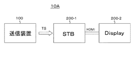
図1は、第1の実施の形態としての送受信システム10の構成例を示している。この送受信システム10は、送信装置100と、テレビ受信機200を有する構成となっている。
<1. First Embodiment>
[Transmission / reception system]
FIG. 1 shows a configuration example of the transmission /
送信装置100は、コンテナとしてのトランスポートストリームTSを放送波に載せて送信する。このトランスポートストリームTSには、120Hz、240Hz等のハイフレームレート、この実施の形態においては120Hzの動画像データが処理されて得られた基本ストリーム(基本ビデオストリーム)および拡張ストリーム(拡張ビデオストリーム)が含まれる。この実施の形態において、基本ストリームおよび拡張ストリームは、NALユニット構造を有するものとされる。
The
ここで、基本ストリームは、以下のようにして得られたものである。すなわち、混合前のハイフレームレートの動画像データの各フレームの画像データにフレーム毎に独立しかつデータレベルに応じた混合割合で周辺フレームの画像データを混合する処理を施して混合処理後の動画像データが得られる。 Here, the basic stream is obtained as follows. That is, the image data of each frame of the high frame rate moving image data before mixing is processed to mix the image data of the peripheral frames independently for each frame and at the mixing ratio according to the data level, and the moving image after the mixing process is performed. Image data is obtained.
この混合処理後の動画像データを構成する各フレームの画像データのうち、少なくとも、ノーマルフレームレート、この実施の形態では60Hzに対応したフレームの画像データは周辺フレームの画像データと混合された状態とされる。基本ストリームは、このノーマルフレームレートに対応したフレーム(基本フレーム)の画像データが符号化されて得られたものである。また、拡張ストリームは、残りのフレーム(拡張フレーム)の画像データが符号化されて得られたものである。 Of the image data of each frame constituting the moving image data after the mixing process, at least the image data of the frame corresponding to the normal frame rate, 60 Hz in this embodiment, is in a state of being mixed with the image data of the peripheral frame. Will be done. The basic stream is obtained by encoding the image data of the frame (basic frame) corresponding to this normal frame rate. Further, the extended stream is obtained by encoding the image data of the remaining frames (extended frames).
基本ストリームには、ノーマルフレームレートの各フレームの符号化画像データがアクセスユニットとして含まれる。また、拡張ストリームには、ハイフレームレートの各拡張フレームの符号化画像データがアクセスユニットとして含まれる。 The basic stream contains coded image data of each frame at a normal frame rate as an access unit. In addition, the extended stream contains coded image data of each extended frame at a high frame rate as an access unit.
図2(a),(b)は、120Hzの動画像データに混合処理が施されて得られた60Hzの基本ストリームと、+60Hzの拡張ストリームの一例を示している。基本ストリームを構成する一つのフレームと、それに続く拡張フレームの1つのフレームからなる2フレームによりフレームペア(Frame-pair)が構成されている。 FIGS. 2A and 2B show an example of a 60 Hz basic stream and a + 60 Hz extended stream obtained by mixing 120 Hz moving image data. A frame-pair is composed of two frames consisting of one frame constituting the basic stream and one frame of the expansion frame following it.
図2(a)においては、各フレームペアにおいて、最初のフレームである基本ストリームのフレームの画像データは周辺フレームの画像データと混合された状態(混合状態)にあるが、それに続く拡張ストリームのフレームの画像データは周辺フレームの画像データと混合されていない状態(非混合状態)にある。また、図2(b)においては、各フレームペアにおいて、最初のフレームである基本ストリームのフレームの画像データは周辺フレームの画像データと混合された状態(混合状態)にあるが、それに続く拡張ストリームのフレームの画像データも周辺フレームの画像データと混合された状態(混合状態)にある。 In FIG. 2A, in each frame pair, the image data of the frame of the basic stream, which is the first frame, is in a state of being mixed with the image data of the peripheral frames (mixed state), but the frame of the extended stream following it. The image data of is not mixed with the image data of the peripheral frame (non-mixed state). Further, in FIG. 2B, in each frame pair, the image data of the frame of the basic stream, which is the first frame, is in a state of being mixed with the image data of the peripheral frames (mixed state), but the subsequent extended stream. The image data of the frame is also in a state of being mixed with the image data of the peripheral frames (mixed state).
ビデオ(ビデオストリーム)のレイヤおよび/またはコンテナのレイヤに、混合割合の情報および画像データのレンジ情報が挿入される。ここで、混合割合の情報は、混合処理に使用されるフィルタのタップ数分の係数のセットからなっている。例えば、mフレームの混合を行い得るmタップのフィルタが用いられる場合、各フレームの係数セットにはm個の係数が含まれる。 Mix ratio information and image data range information are inserted into the video (video stream) layer and / or the container layer. Here, the mixing ratio information consists of a set of coefficients for the number of taps of the filter used in the mixing process. For example, when an m-tap filter capable of mixing m-frames is used, the coefficient set for each frame contains m coefficients.
また、画像データのレンジ情報は、第1の閾値と、この第1の閾値より低い第2の閾値の情報を含んでいる。また、この実施の形態において、上述の120Hzの動画像データは、HDRの動画像データである。 Further, the range information of the image data includes the information of the first threshold value and the information of the second threshold value lower than the first threshold value. Further, in this embodiment, the 120 Hz moving image data described above is HDR moving image data.
図3は、HDRの光電変換特性の一例を示している。この図において、横軸は輝度を示し、縦軸は伝送符号値を示している。第1の閾値は、SDR(Standard Dynamic Range)相当の輝度(100cd/m2)に対応するレベル値“Range_limit_High_value”とされ、画像データのレベルが特殊混合処理対象範囲であるきらめき再現レベルの範囲にあるか否かを判別するための閾値である。また、第2の閾値は、レベル値“Range_limit_low_value”とされ、画像データのレベルが特殊混合処理対象範囲である暗部再現レベルの範囲にあるか否かを判別するための閾値である。 FIG. 3 shows an example of the photoelectric conversion characteristics of HDR. In this figure, the horizontal axis represents the luminance and the vertical axis represents the transmission code value. The first threshold value is the level value "Range_limit_High_value" corresponding to the luminance (100 cd / m 2 ) equivalent to SDR (Standard Dynamic Range), and the level of the image data is within the range of the glitter reproduction level which is the target range of the special mixing process. It is a threshold value for determining whether or not there is. Further, the second threshold value is a level value "Range_limit_low_value", and is a threshold value for determining whether or not the level of the image data is within the range of the dark area reproduction level which is the special mixing processing target range.
上述したようにハイフレームレートの動画像データの各フレームの画像データにフレーム毎に独立しかつデータレベルに応じた混合割合で周辺フレームの画像データが混合される。処理対象フレームの画像データに周辺フレームの画像データを混合する処理がされるとき、画素単位で、上述の“Range_limit_High_value”、“Range_limit_low_value”のレベル値が用いられて混合割合が決定される。 As described above, the image data of the peripheral frames is mixed with the image data of each frame of the high frame rate moving image data independently for each frame and at a mixing ratio according to the data level. When the processing of mixing the image data of the peripheral frame with the image data of the processing target frame is performed, the mixing ratio is determined by using the above-mentioned level values of "Range_limit_High_value" and "Range_limit_low_value" for each pixel.
この混合割合の決定は、新規方法1あるいは新規方法2で行われる。新規方法1では、処理対象フレームの画像データに基づいて混合割合が決定される。一方、新規方法2では、処理対象フレームおよび周辺フレームの画像データに基づいて混合割合が決定される。
The determination of the mixing ratio is performed by the
この実施の形態において、混合割合の情報(係数セット)および画像データのレンジ情報を持つSEI NALユニットが、基本ストリームや拡張ストリームに挿入される。受信側では、この混合割合の情報および画像データのレンジ情報に基づいて、基本ストリームおよび拡張ストリームの各フレームの画像データがいかなる割合で周辺フレームの画像データと混合されて得られたものであるかが把握可能となる。 In this embodiment, the SEI NAL unit having the mixing ratio information (coefficient set) and the range information of the image data is inserted into the basic stream or the extended stream. On the receiving side, based on this mixing ratio information and the range information of the image data, what ratio is the image data of each frame of the basic stream and the extended stream obtained by being mixed with the image data of the peripheral frames? Can be grasped.
図1に戻って、テレビ受信機200は、送信装置100から放送波に載せて送られてくる上述のトランスポートストリームTSを受信する。テレビ受信機200は、ノーマルフレームレート(60Hz)の動画像データを処理可能なデコード能力がある場合、トランスポートストリームTSに含まれる基本ストリームのみを処理して、ノーマルフレームレートの動画像データを得て、画像再生をする。
Returning to FIG. 1, the
一方、テレビ受信機200は、ハイフレームレート(120Hz)の動画像データを処理可能なデコード能力がある場合、トランスポートストリームTSに含まれる基本ストリームおよび拡張ストリームの双方を処理して、ハイフレームレートの動画像データを得て、画像再生をする。テレビ受信機200は、ビデオ(ビデオストリーム)のレイヤおよび/またはコンテナのレイヤの挿入されている混合割合の情報および画像データのレンジ情報を取得し、これらの情報を用いて混合分離処理(逆混合処理)をする。
On the other hand, if the
この場合、テレビ受信機200は、基本ストリームに復号化処理を施してノーマルフレームレートの各フレームの画像データを得ると共に、拡張ストリームに復号化処理を施してハイフレームレートの各拡張フレームの画像データを得た後、ノーマルフレームレートの各フレームの画像データとハイフレームレートの各拡張フレームの画像データを用い、混合割合の情報(係数セット)に基づいて、混合分離処理(逆混合処理)を行って、混合処理前と同様のハイフレームレートの動画像データを得る。
In this case, the
図4は、送信装置100およびテレビ受信機200(200A,200B)の処理の概要を示している。なお、送信装置100のプリプロセッサ102の出力の画像シーケンスP´(N)、P(N+1)とテレビ受信機200A,200Bのデコーダ204,204Bの出力の画像シーケンスP´(N)、P(N+1)とは、時系列的には同じものであるが、コーデックを通しているので両者の画質が異なる場合も含む。カメラ(撮像装置)81から出力されるより高いフレームレートの動画像データVaがHFRプロセッサ82に送られてハイフレームレート(120Hz)の動画像データVbが得られる。この動画像データVbが送信装置100に動画像データPとして入力される。
FIG. 4 shows an outline of processing of the
送信装置100では、プリプロセッサ102において、動画像データPを構成する各フレームの画像データに混合処理が施されて、ノーマルフレームレートの各フレームの画像データP´(N)と、ハイフレームレートの各拡張フレームの画像データP(N+1)が得られる。なお、この実施の形態において、画像データP(N+1)には、周辺フレームの画像データとの混合は行われていない。
In the
送信装置100では、エンコーダ103において、画像データP´(N),P(N+1)に符号化処理が施されて、基本ストリームSTbと、拡張ストリームSTeが得られる。送信装置100からテレビ受信機200には、これらのストリームSTb,STeが送信される。なお、これらのストリームSTb,STeには、それぞれのフレームの画像データに関連付けて、対応するフレームの混合割合の情報および画像データのレンジ情報が挿入される。
In the
ハイフレームレート対応の、つまりハイフレームレートの動画像データを処理可能なデコード能力があるテレビ受信機200Aでは、デコーダ204において、2つのストリームSTb,STeに復号化処理が施されて、ノーマルフレームレートの各フレームの画像データP´(N)と、ハイフレームレートの各拡張フレームの画像データP(N+1)が得られる。
In the
そして、テレビ受信機200Aでは、ポストプロセッサ205において、各フレームの混合割合の情報および画像データのレンジ情報に基づいて、動画像データP´(N),P(N+1)に混合分離処理(逆混合処理)が施されて、送信側における動画像データPと同様のハイフレームレート(120Hz)の動画像データRが得られる。この動画像データRが、そのまま、あるいはMCFI(Motion Compensated Frame Insertion)部206でフレーム補間がされてフレームレートが高められて表示用動画像データとなる。
Then, in the
一方、ノーマルフレームレート対応の、つまりノーマルフレームレートの画像データを処理可能なデコード能力があるテレビ受信機200Bでは、デコーダ204Bにおいて、ストリームSTbに復号化処理が施されて、ノーマルフレームレートの各フレームの画像データP´(N)が得られる。そして、テレビ受信機200Bでは、このノーマルフレームレートの各フレームの画像データP´(N)からなる動画像データが、そのまま、あるいはMCFI(Motion Compensated Frame Insertion)部206Bでフレーム補間がされてフレームレートが高められて表示用動画像データとなる。
On the other hand, in the
図5は、送信側における混合(blending)と、受信側における混合分離(unblending)の一例を模式的に示している。この例は、図2(a)の例に対応し、ピクチャ「N」とピクチャ「N+1」がフレームペアを構成しており、ピクチャ「N+2」とピクチャ「N+3」がフレームペアを構成している。なお、図示の例において、オブジェクトOa,Obは動きのないオブジェクトであり、オブジェクトOcは動きのあるオブジェクトである。 FIG. 5 schematically shows an example of mixing (blending) on the transmitting side and mixing separation (unblending) on the receiving side. This example corresponds to the example of FIG. 2A, in which the picture "N" and the picture "N + 1" form a frame pair, and the picture "N + 2" and the picture "N + 3" form a frame pair. .. In the illustrated example, the objects Oa and Ob are non-moving objects, and the object Occ is a moving object.
送信側の混合処理により、各フレームペアにおいて、最初のフレームである基本ストリームのフレームの画像データは周辺フレームの画像データと混合された状態(混合状態)とされ、それに続く拡張ストリームのフレームの画像データは周辺フレームの画像データと混合されていない状態(非混合状態)とされる。また、受信側の混合分離処理(逆混合処理)により、混合状態が解除される。 Due to the mixing process on the transmitting side, in each frame pair, the image data of the frame of the basic stream, which is the first frame, is made to be mixed with the image data of the peripheral frame (mixed state), and the image of the frame of the subsequent extended stream is made. The data is not mixed with the image data of the peripheral frame (non-mixed state). Further, the mixing state is released by the mixing / separating process (reverse mixing process) on the receiving side.
図6は、混合割合の決定方法として従来方法を採用した場合におけるプリプロセッサ102とポストプロセッサ205の処理の概要を示している。図6(a)は、プリプロセッサ102で混合処理がなされる前のピクチャ「N」の画像を示し、図6(b)は、プリプロセッサ102で混合処理がなされる前のピクチャ「N+1」の画像を示し、図6(c)は、プリプロセッサ102で混合処理がなされた後のピクチャ「N」の画像を示している。
FIG. 6 shows an outline of the processing of the
ピクチャ「N」の画像上の点P(N)は、ピクチャ「N+1」上の同じ座標位置にある点P(N+1)と、以下のタイプ0(Type 0)の混合処理が行われ、P’(N)の値はP(N)、P(N+1)の算術平均(重みは許容)をとった値となる。点P(N)が高輝度で点P(N+1)が高輝度でない場合は算術平均をとることで混合結果としてのP’(N)の輝度レベルが下がる。ハイフレームレート対応でないテレビ受信機200Bでは、この混合結果による画像表示がなされるので、きらめき感が失われた画像が表示されることとなる。
[ Type0 混合処理 ]
P’(N) = (a/k) * P(N) + ( b/k ) * P(N+1) (a + b = k)
The point P (N) on the image of the picture "N" is mixed with the point P (N + 1) at the same coordinate position on the picture "N + 1" and the following type 0 (Type 0), and P'. The value of (N) is the value obtained by taking the arithmetic mean (weight is permissible) of P (N) and P (N + 1). When the point P (N) has high brightness and the point P (N + 1) does not have high brightness, the brightness level of P'(N) as a result of mixing is lowered by taking the arithmetic mean. In the
[Type0 mixed processing]
P'(N) = (a / k) * P (N) + (b / k) * P (N + 1) (a + b = k)
図6(d)は、ポストプロセッサ205で混合分離処理がなされた後のピクチャ「N」の画像を示し、図6(e)は、ポストプロセッサ205で用いられるピクチャ「N+1」の画像を示している。ハイフレームレート対応のテレビ受信機200Aでは、ポストプロセッサ205において、以下のタイプ0(Type 0)の混合分離処理が行われて、P”(N)の値が得られる。このように、ハイフレームレート対応のテレビ受信機200Aでは、混合分離処理により、きらめき感が復元される。
[ Type0 混合分離処理]
P”(N) = k/a * P'(N) - b/a * P(N+1) (a + b = k)
FIG. 6 (d) shows an image of the picture “N” after the mixing and separation processing is performed by the
[Type0 mixed separation process]
P ”(N) = k / a * P'(N) --b / a * P (N + 1) (a + b = k)
図7は、混合割合の決定方法として新規方法1を採用した場合におけるプリプロセッサ102とポストプロセッサ205の処理の概要を示している。図7(a)は、プリプロセッサ102で混合処理がなされる前のピクチャ「N」の画像を示し、図7(b)は、プリプロセッサ102で混合処理がなされる前のピクチャ「N+1」の画像を示し、図7(c)は、プリプロセッサ102で混合処理がなされた後のピクチャ「N」の画像を示している。
FIG. 7 shows an outline of the processing of the
ピクチャ「N」上の点P(N)を、ピクチャ「N+1」上の同じ座標位置にある点P(N+1)と混合する際に、重要な輝度・色度感を維持しながら、画素の混合を行うようにする。維持する画素値のレベル範囲を特殊混合処理対象範囲とし、それに合致する画素については特殊混合を行う。すなわち、通常の混合処理「 Type0 混合処理 」とは混合割合を変えるか、あるいは混合を行わないようにする。 Pixel mixing while maintaining important brightness and chromaticity when mixing point P (N) on picture "N" with point P (N + 1) at the same coordinate position on picture "N + 1" To do. The level range of the pixel values to be maintained is set as the special mixing processing target range, and special mixing is performed for the pixels matching the level range. That is, the mixing ratio is changed from the normal mixing process "Type0 mixing process", or mixing is not performed.
ピクチャ「N」の画像上の点P(N)の画素値が特殊混合処理対象範囲にないとき、ピクチャ「N」の画像上の点P(N)は、ピクチャ「N+1」上の同じ座標位置にある点P(N+1)と、以下のタイプ0(Type 0)の混合処理(通常混合処理)が行われ、P’(N)の値はP(N)、P(N+1)の算術平均(重みは許容)をとった値となる。
[ Type0 混合処理 ]
P’(N) = (a/k) * P(N) + ( b/k ) * P(N+1) (a + b = k)
When the pixel value of the point P (N) on the image of the picture "N" is not in the special mixing processing target range, the point P (N) on the image of the picture "N" has the same coordinate position on the picture "N + 1". The point P (N + 1) at the point P (N + 1) and the following type 0 (Type 0) are mixed (normally mixed), and the value of P'(N) is the arithmetic average of P (N) and P (N + 1) ( The weight is acceptable).
[Type0 mixed processing]
P'(N) = (a / k) * P (N) + (b / k) * P (N + 1) (a + b = k)
一方、ピクチャ「N」の画像上の点P(N)の画素値が特殊混合処理対象範囲にあるとき、ピクチャ「N」の画像上の点P(N)は、ピクチャ「N+1」上の同じ座標位置にある点P(N+1)と、以下のタイプ1(Type 1)の混合処理(特殊混合処理)が行われ、P’(N)の値はP(N)、P(N+1)の算術平均(重みは許容)をとった値となる。これにより、通常輝度色度範囲については混合の効果が得られ、きらめき部分およびダーク部分での先鋭感が損なわれることなく、受信再生が可能となる。
[ Type1 混合処理 ]
P’(N) = (c/m) * P(N) + ( d/m ) * P(N+1) (c + d = m)
P’(N) = P(N) (c = m の場合)
On the other hand, when the pixel value of the point P (N) on the image of the picture "N" is within the special mixing processing target range, the point P (N) on the image of the picture "N" is the same on the picture "N + 1". The point P (N + 1) at the coordinate position and the following type 1 (Type 1) mixing process (special mixing process) are performed, and the value of P'(N) is the arithmetic of P (N) and P (N + 1). The value is the average (weight is acceptable). As a result, the effect of mixing is obtained in the normal luminance chromaticity range, and reception and reproduction are possible without impairing the sharpness in the glittering portion and the dark portion.
[Type1 mixed processing]
P'(N) = (c / m) * P (N) + (d / m) * P (N + 1) (c + d = m)
P'(N) = P (N) (when c = m)
図7(d)は、ポストプロセッサ205で混合分離処理がなされた後のピクチャ「N」の画像を示し、図7(e)は、ポストプロセッサ205で用いられるピクチャ「N+1」の画像を示している。
FIG. 7 (d) shows an image of the picture “N” after the mixing and separation processing is performed by the
ハイフレームレート対応のテレビ受信機200Aでは、点P’(N)の画素値が特殊混合処理対象範囲にないとき、あるいは点P’(N)の画素値が特殊混合処理対象範囲にあり、かつ点P(N+1)が特殊混合処理対象範囲にあるとき、ポストプロセッサ205において、以下のタイプ0(Type 0)の混合分離処理が行われて、P”(N)の値が得られる。
[Type0 混合分離処理]
P”(N) = k/a * P’(N) - b/a * P(N+1) (a + b = k)
In the high frame rate
[Type0 mixed separation processing]
P ”(N) = k / a * P'(N) --b / a * P (N + 1) (a + b = k)
一方、ハイフレームレート対応のテレビ受信機200Aでは、点P’(N)の画素値が特殊混合処理対象範囲にあり、かつ点P(N+1)が特殊混合処理対象範囲にないとき、ポストプロセッサ205において、以下のタイプ1(Type 1)の混合分離処理が行われて、P”(N)の値が得られる。
[Type1 混合分離処理]
P”(N) = m/c * P’(N) - d/c * P(N+1) (c + d = m)
P”(N) = P’(N) ( c = m の場合)
On the other hand, in the high frame rate
[Type1 mixed separation processing]
P ”(N) = m / c * P'(N) --d / c * P (N + 1) (c + d = m)
P ”(N) = P'(N) (when c = m)
図8は、上述したように混合割合の決定方法として新規方法1を採用した場合におけるプリプロセッサ102における混合処理とポストプロセッサ205における混合分離処理(逆混合処理)の決定ロジックを示している。
FIG. 8 shows the determination logic of the mixing process in the
図において、“range_high”は、画像データのレベルが特殊混合処理対象範囲であるきらめき再現レベルの範囲にあるか否かを判別するための閾値であるレベル値“Range_limit_high_value”を示している。また、“range_low”は、画像データのレベルが特殊混合処理対象範囲である暗部再現レベルの範囲にあるか否かを判別するための閾値であるレベル値“Range_limit_low_value”を示している(図3参照)。 In the figure, “range_high” indicates a level value “Range_limit_high_value” which is a threshold value for determining whether or not the level of the image data is within the range of the sparkle reproduction level which is the special mixing processing target range. Further, “range_low” indicates a level value “Range_limit_low_value” which is a threshold value for determining whether or not the level of the image data is within the range of the dark area reproduction level which is the special mixing processing target range (see FIG. 3). ).
プリプロセッサ102における混合処理では、P(N)が「P(N) > range_high or P(N) < range_low」を満たすときは、「 Type1 混合処理(Type1_blending()) 」を行うように決定される。このときの処理結果であるP’(N)は、特殊混合処理対象範囲となる。また、プリプロセッサ102における混合処理では、その他のときは、「 Type0 混合処理(Type1_blending() )」を行うように決定される。このときの処理結果であるP’(N)が通常混合処理対象範囲に入るか否かは、P(N+1)に依存する。
In the mixing process in the
また、ポストプロセッサ205における混合処理では、P’(N)が「P'(N) > range_high 」を満たす場合、P(N+1)が「P(N+1) =< range_high 」を満たすときは「 Type1 混合分離処理(Type1_reverse_blending()) 」を行うように決定され、その他のときは、「 Type0 混合分離処理(Type0_reverse_blending()) 」を行うように決定される。
Further, in the mixing process in the
また、ポストプロセッサ205における混合処理では、P’(N)が「P'(N) < range_low 」を満たす場合、P(N+1)が「P(N+1) >= range_low 」を満たすときは「 Type1 混合分離処理(Type1_reverse_blending()) 」を行うように決定され、その他のときは、「 Type0 混合分離処理(Type0_reverse_blending()) 」を行うように決定される。
Further, in the mixing process in the
また、ポストプロセッサ205における混合処理では、その他の場合、「 Type0 混合分離処理(Type0_reverse_blending()) 」を行うように決定される。
Further, in the mixing process in the
図9は、混合割合の決定方法として新規方法2を採用した場合におけるプリプロセッサ102とポストプロセッサ205の処理の概要を示している。図9(a)は、プリプロセッサ102で混合処理がなされる前のピクチャ「N」の画像を示し、図9(b)は、プリプロセッサ102で混合処理がなされる前のピクチャ「N+1」の画像を示し、図9(c)は、プリプロセッサ102で混合処理がなされた後のピクチャ「N」の画像を示している。
FIG. 9 shows an outline of the processing of the
ピクチャ「N」上の点P(N)を、ピクチャ「N+1」上の同じ座標位置にある点P(N+1)と混合する際に、重要な輝度・色度感を維持しながら、画素の混合を行うようにする。維持する画素値のレベル範囲を特殊混合処理対象範囲とし、それに合致する画素については特殊混合を行う。すなわち、通常の混合処理「 Type0 混合処理 」とは混合割合を変えるか、あるいは混合を行わないようにする。 Pixel mixing while maintaining important brightness and chromaticity when mixing point P (N) on picture "N" with point P (N + 1) at the same coordinate position on picture "N + 1" To do. The level range of the pixel values to be maintained is set as the special mixing processing target range, and special mixing is performed for the pixels matching the level range. That is, the mixing ratio is changed from the normal mixing process "Type0 mixing process", or mixing is not performed.
ピクチャ「N」の画像上の点P(N)の画素値が特殊混合処理対象範囲になく、かつピクチャ「N+1」の画像上の点P(N+1)の画素値が特殊混合処理対象範囲にないとき、ピクチャ「N」の画像上の点P(N)は、ピクチャ「N+1」上の同じ座標位置にある点P(N+1)と、以下のタイプ0(Type 0)の混合処理(通常混合処理)が行われ、P’(N)の値はP(N)、P(N+1)の算術平均(重みは許容)をとった値となる。
[ Type0 混合処理 ]
P’(N) = (a/k) * P(N) + ( b/k ) * P(N+1) (a + b = k)
The pixel value of the point P (N) on the image of the picture "N" is not in the special mixing processing target range, and the pixel value of the point P (N + 1) on the image of the picture "N + 1" is not in the special mixing processing target range. When the point P (N) on the image of the picture "N" is a mixing process (normal mixing process) of the point P (N + 1) at the same coordinate position on the picture "N + 1" and the following type 0 (
[Type0 mixed processing]
P'(N) = (a / k) * P (N) + (b / k) * P (N + 1) (a + b = k)
一方、ピクチャ「N」の画像上の点P(N)の画素値が特殊混合処理対象範囲にあるとき、ピクチャ「N」の画像上の点P(N)aは、ピクチャ「N+1」上の同じ座標位置にある点P(N+1)aと、以下のタイプ1(Type 1)の混合処理(特殊混合処理)が行われ、P’(N)の値はP(N)、P(N+1)の算術平均(重みは許容)をとった値となる。
[ Type1 混合処理 ]
P’(N) = (c/m) * P(N) + ( d/m ) * P(N+1) ( c + d = m)
P’(N) = P(N) (c = m の場合)
On the other hand, when the pixel value of the point P (N) on the image of the picture "N" is within the special mixing processing target range, the point P (N) a on the image of the picture "N" is on the picture "N + 1". The point P (N + 1) a at the same coordinate position and the following type 1 (Type 1) mixing process (special mixing process) are performed, and the values of P'(N) are P (N) and P (N + 1). It is a value obtained by taking the arithmetic mean of (weight is acceptable).
[Type1 mixed processing]
P'(N) = (c / m) * P (N) + (d / m) * P (N + 1) (c + d = m)
P'(N) = P (N) (when c = m)
また、ピクチャ「N」の画像上の点P(N)の画素値が特殊混合処理対象範囲にないが、ピクチャ「N+1」の画像上の点P(N+1)の画素値が特殊混合処理対象範囲にあるとき、ピクチャ「N」の画像上の点P(N)bは、ピクチャ「N+1」上の同じ座標位置にある点P(N+1)と、以下のタイプ2(Type 2)の混合処理(特殊混合処理)が行われ、P’(N)の値はP(N)、P(N+1)の算術平均(重みは許容)をとった値となる。これにより、通常輝度色度範囲については混合の効果が得られ、きらめき部分およびダーク部分での先鋭感が損なわれることなく、受信再生が可能となる。
[ Type2 混合処理 ]
P’(N) = (e/s) * P(N) + (f/s)* P(N+1) (e < f かつe + f = s)
Further, although the pixel value of the point P (N) on the image of the picture "N" is not in the special mixing processing target range, the pixel value of the point P (N + 1) on the image of the picture "N + 1" is in the special mixing processing target range. When the point P (N) b on the image of the picture "N" is, the point P (N + 1) at the same coordinate position on the picture "N + 1" and the following type 2 (Type 2) are mixed (Type 2). (Special mixing process) is performed, and the value of P'(N) is the value obtained by taking the arithmetic mean (weight is acceptable) of P (N) and P (N + 1). As a result, the effect of mixing is obtained in the normal luminance chromaticity range, and reception and reproduction are possible without impairing the sharpness in the glittering portion and the dark portion.
[Type2 mixed processing]
P'(N) = (e / s) * P (N) + (f / s) * P (N + 1) (e <f and e + f = s)
図9(d)は、ポストプロセッサ205で混合分離処理がなされた後のピクチャ「N」の画像を示し、図9(e)は、ポストプロセッサ205で用いられるピクチャ「N+1」の画像を示している。
FIG. 9 (d) shows an image of the picture “N” after the mixing and separation processing is performed by the
ハイフレームレート対応のテレビ受信機200Aでは、点P’(N)の画素値が特殊混合処理対象範囲にないとき、ポストプロセッサ205において、以下のタイプ0(Type 0)の混合分離処理が行われて、P”(N)の値が得られる。
[Type0 混合分離処理]
P”(N) = k/a * P'(N) - b/a * P(N+1) (a + b = k)
In the high frame rate
[Type0 mixed separation processing]
P ”(N) = k / a * P'(N) --b / a * P (N + 1) (a + b = k)
一方、ハイフレームレート対応のテレビ受信機200Aでは、点P’(N)の画素値が特殊混合処理対象範囲にあり、かつ点P(N+1)の画素値が特殊混合処理対象範囲にないとき、ポストプロセッサ205において、以下のタイプ1(Type 1)の混合分離処理が行われて、P”(N)の値が得られる。
[Type1 混合分離処理]
P”(N) = m/c * P'(N) - d/c * P(N+1) (c + d = m)
P”(N) = P’(N) ( c = m の場合)
On the other hand, in the high frame rate
[Type1 mixed separation processing]
P ”(N) = m / c * P'(N) --d / c * P (N + 1) (c + d = m)
P ”(N) = P'(N) (when c = m)
また、ハイフレームレート対応のテレビ受信機200Aでは、点P’(N)の画素値が特殊混合処理対象範囲にあり、かつ点P(N+1)の画素値が特殊混合処理対象範囲にあるとき、ポストプロセッサ205において、以下のタイプ2(Type 2)の混合分離処理が行われて、P”(N)の値が得られる。
[Type2 混合分離処理]
P”(N) = s/e * P'(N) - f/e * P(N+1) (e + f = s)
Further, in the high frame rate
[Type2 mixed separation processing]
P ”(N) = s / e * P'(N) --f / e * P (N + 1) (e + f = s)
図10は、上述したように混合割合の決定方法として新規方法2を採用した場合におけるプリプロセッサ102における混合処理とポストプロセッサ205における混合分離処理(逆混合処理)の決定ロジックを示している。
FIG. 10 shows the determination logic of the mixing process in the
図において、“range_high”は、画像データのレベルが特殊混合処理対象範囲であるきらめき再現レベルの範囲にあるか否かを判別するための閾値であるレベル値“Range_limit_high_value”を示している。また、“range_low”は、画像データのレベルが特殊混合処理対象範囲である暗部再現レベルの範囲にあるか否かを判別するための閾値であるレベル値“Range_limit_low_value”を示している(図3参照)。 In the figure, “range_high” indicates a level value “Range_limit_high_value” which is a threshold value for determining whether or not the level of the image data is within the range of the sparkle reproduction level which is the special mixing processing target range. Further, “range_low” indicates a level value “Range_limit_low_value” which is a threshold value for determining whether or not the level of the image data is within the range of the dark area reproduction level which is the special mixing processing target range (see FIG. 3). ).
プリプロセッサ102における混合処理では、P(N)が「P(N) > range_high or P(N) < range_low」を満たすときは、「 Type1 混合処理(Type1_blending) 」を行うように決定される。このときの処理結果であるP’(N)は、特殊混合処理対象範囲となる。また、プリプロセッサ102における混合処理では、P(N) が「range_low =< P(N) =< range_high 」を満たし、且つ、P(N+1)が「P(N+1) > range_high or P(N+1) < range_low 」を満たすときは、「 Type2 混合処理(Type2_blending) 」を行うように決定される。このときの処理結果であるP’(N)は、特殊混合処理対象範囲となる。また、その他のときは、「 Type0 混合処理(Type0_blending) 」を行うように決定される。このときの処理結果であるP’(N)は、通常混合処理対象範囲となる。
In the mixing process in the
また、ポストプロセッサ205における混合処理では、P’(N)が「P’(N) > range_high」を満たし、且つ、P(N+1)が「P(N+1) > range_high」を満たすときは、「 Type2 混合分離処理(Type2_reverse_blending()) 」を行うように決定され、P’(N)が「P’(N) > range_high」を満たし、且つ、P(N+1)が「P(N+1) > range_high」を満たさないときは、「 Type1 混合分離処理(Type1_reverse_blending()) 」を行うように決定さる。
Further, in the mixing process in the
また、ポストプロセッサ205における混合処理では、P’(N)が「P’(N) < range_low」を満たし、且つ、P(N+1)が「P(N+1) < range_low」を満たすときは、「 Type2 混合分離処理(Type2_reverse_blending()) 」を行うように決定され、P’(N)が「P’(N) < range_low」を満たし、且つ、P(N+1)が「P(N+1) < range_low」を満たさないときは、「 Type1 混合分離処理(Type1_reverse_blending()) 」を行うように決定さる。
Further, in the mixing process in the
また、ポストプロセッサ205における混合処理では、その他の場合、「 Type0 混合分離処理(Type0_reverse_blending()) 」を行うように決定さる。
Further, in the mixing process in the
「送信装置の構成」
図11は、送信装置100の構成例を示している。この送信装置100は、制御部101と、プリプロセッサ102と、エンコーダ103と、マルチプレクサ104と、送信部105を有している。制御部101は、送信装置100の各部の動作を制御する。
"Configuration of transmitter"
FIG. 11 shows a configuration example of the
プリプロセッサ102は、ハイフレームレート(120Hz)の動画像データPを入力して、ノーマルフレームレート(60Hz)の各フレームの画像データP’(N)と、ハイフレームレートの各拡張フレームの画像データP(N+1)を出力する。
The
ここで、プリプロセッサ102は、混合処理前のハイフレームレートの動画像データPの各フレームの画像データにフレーム毎に独立しかつデータレベルに応じた混合割合で周辺フレームの画像データを混合する処理を施して混合処理後の動画像データを得る。この動画像データのうち、ノーマルフレームレート(60Hz)に対応した各フレームの画像データがP’(N)となり、残りの各フレームの画像データがP(N+1)となる。この場合、少なくとも、画像データP’(N)は周辺フレームの画像データと混合された状態とされる。
Here, the
図12は、プリプロセッサ102の構成例を示している。この例は、混合割合の決定方法として新規方法1を採用した場合における構成例である。このプリプロセッサ102は、ピクセル処理部120と、フレーム遅延部121と、係数器122,123,125,126と、加算部124,127と、スイッチ部128と、出力部129を有している。
FIG. 12 shows a configuration example of the
ピクセル処理部120は、動画像データPの各フレームの画像データP(N),P(N+1)の値を調整して、“Range_limit_high_value”、“Range_limit_low_value”のレベル値による特殊混合処理対象範囲にあるか否かの判定処理を適切に行い得るようにする。
The
図13は、ピクセル処理部120で使用される上限値用テーブルの一例を示している。図14は、ピクセル処理部120で使用される下限値用テーブルの一例を示している。ここでは、画像データは10ビットデータを例にとり、下限値64、上限値940で説明する。
FIG. 13 shows an example of an upper limit value table used by the
最初に、図13に示す上限値用テーブル例について説明する。このテーブル例は、“Range_limit_High_value”を700に設定する場合の例である。701〜705は705に変更され、706〜940はそのままの値が保持される。同様に、698〜700は698に変更され、64〜697は、そのままの値が保持される。 First, an example of the upper limit value table shown in FIG. 13 will be described. This table example is an example when "Range_limit_High_value" is set to 700. 701 to 705 are changed to 705, and 706 to 940 keep the same values. Similarly, 698-700 is changed to 698, and 64-697 keeps the same value.
ここで、P(N)の値が705以上のとき、特殊混合処理対象範囲にあると判断され、プリプロセッサ102では「 Type1 混合処理 」の混合処理が行われる。この場合、P'(N)の値の最小値は、P(N+1)の値が64以上であることから、例えばP(N)とP(N+1)との混合割合が255:1に設定されるときには、以下の数式(1)から、702となる。
P’(N) = (705*255 + 64*1 )/256 = 702 ・・・(1)
Here, when the value of P (N) is 705 or more, it is determined that the value is within the special mixing processing target range, and the
P'(N) = (705 * 255 + 64 * 1) / 256 = 702 ・ ・ ・ (1)
そのため、ポストプロセッサ205側においても、P'(N)の値から、同様に、特殊混合処理対象範囲と判断することが可能となり、適切な混合分離処理(逆混合処理)を行うことが可能となる。なお、詳細説明は省略するが、“Range_limit_High_value”を700以外の値に設定する場合にあっても、画像データP(N),P(N+1)の値を調整することで、同様の効果を持たせることができる。 Therefore, even on the post-processor 205 side, it is possible to similarly determine the range to be subject to special mixing processing from the value of P'(N), and it is possible to perform appropriate mixing / separation processing (reverse mixing processing). Become. Although detailed description is omitted, even when "Range_limit_High_value" is set to a value other than 700, the same effect can be obtained by adjusting the values of the image data P (N) and P (N + 1). Can be made.
次に、図14に示す下限値用テーブル例について説明する。このテーブル例は、“Range_limit_Low_value”を100に設定する場合の例である。96〜99は96に変更され、64〜95はそのままの値が保持される。同様に、100〜102は102に変更され、103〜940は、そのままの値が保持される。 Next, an example of the lower limit value table shown in FIG. 14 will be described. This table example is an example when "Range_limit_Low_value" is set to 100. 96 to 99 are changed to 96, and 64 to 95 are kept as they are. Similarly, 100 to 102 are changed to 102, and 103 to 940 are retained as they are.
ここで、P(N)の値が96以下のとき、特殊混合処理対象範囲にあると判断され、プリプロセッサ102では「 Type1 混合処理 」の混合処理が行われる。この場合、P'(N)の値の最大値は、P(N+1)の値が940以下であることから、例えばP(N)とP(N+1)との混合割合が255:1に設定されるときには、以下の数式(2)から、99となる。
P’(N) = (96*255 + 940*1 )/256 = 99 ・・・(2)
Here, when the value of P (N) is 96 or less, it is determined that the value is within the special mixing processing target range, and the
P'(N) = (96 * 255 + 940 * 1) / 256 = 99 ・ ・ ・ (2)
そのため、ポストプロセッサ205側においても、P'(N)の値から、同様に、特殊混合処理対象範囲と判断することが可能となり、適切な混合分離処理(逆混合処理)を行うことが可能となる。なお、詳細説明は省略するが、“Range_limit_Low_value”を100以外の値に設定する場合にあっても、画像データP(N),P(N+1)の値を調整することで、同様の効果を持たせることができる。 Therefore, even on the post-processor 205 side, it is possible to similarly determine the range to be subject to special mixing processing from the value of P'(N), and it is possible to perform appropriate mixing / separation processing (reverse mixing processing). Become. Although detailed description is omitted, even when "Range_limit_Low_value" is set to a value other than 100, the same effect can be obtained by adjusting the values of the image data P (N) and P (N + 1). Can be made.
なお、上述では、上限値用テーブルと下限値用テーブルを備えているように説明したが、これらの2つのテーブルは1つのテーブルとして構成することも可能である。 In the above description, it has been described that the upper limit value table and the lower limit value table are provided, but these two tables can also be configured as one table.
図12に戻って、フレーム遅延部121は、ピクセル処理部120で値が調整された画像データP(N),P(N+1)を入力し、120Hzにおける1フレームの遅延を与える。これにより、フレーム遅延部121の出力がピクチャ「N」の画像データP(N)となるとき、ピクセル処理部120の出力はピクチャ「N+1」の画像データP(N+1)となる。
Returning to FIG. 12, the
フレーム遅延部121から得られる画像データP(N)は、係数器122と係数器125に入力される。また、ピクセル処理部120から得られる画像データP(N+1)は、係数器123と係数器126に入力される。
The image data P (N) obtained from the
係数器122には制御部101から(a/k)の係数が設定されており、画像データP(N)にこの係数が掛け算される。また、係数器123には制御部101から(b/k)の係数が設定されており、画像データP(N+1)にこの係数が掛け算される。係数器122,123の出力値は加算部124で加算される。ここで、係数器122,123および加算部124は、「 Type0 混合処理 」の混合処理を行うためのフィルタを構成しており、加算部124からは「 Type0 混合処理 」の混合処理で得られた画像データP’(N)が得られる。
A coefficient of (a / k) is set in the
また、係数器125には制御部101から(c/m)の係数が設定されており、画像データP(N)にこの係数が掛け算される。また、係数器126には制御部101から(d/m)の係数が設定されており、画像データP(N+1)にこの係数が掛け算される。係数器125,126の出力値は加算部127で加算される。ここで、係数器125,126および加算部127は、「 Type1 混合処理 」の混合処理を行うためのフィルタを構成しており、加算部127からは「 Type1 混合処理 」の混合処理で得られた画像データP’(N)が得られる。
Further, a coefficient (c / m) is set in the
スイッチ部128には、加算部124,127で得られた画像データP’(N)が入力される。スイッチ部128は、制御部101からのセレクト信号に基づき、画素単位で、加算部124で得られた「 Type0 混合処理 」の画像データP’(N)または加算部127で得られた「 Type1 混合処理 」の画像データP’(N)を、選択的に出力する。
The image data P'(N) obtained by the
制御部101は、フレーム遅延部121から得られる画像データP(N)と、予め設定されている“Range_limit_High_value”、“Range_limit_low_value”のレベル値に基づいて、画素単位でセレクト信号を発生してスイッチ部128に送る。
The
図15のフローチャートは、制御部101において画素単位で行われるセレクト信号の発生処理の手順の一例を示している。まず、ステップST1において、制御部101は、処理を開始する。その後、制御部101は、ステップST2において、P(N)の画素を読み込む。次に、制御部101は、ステップST3において、P(N)は特殊混合処理対象範囲「P(N) > range_high, P(N) < range_low」にあるか否かを判定する。
The flowchart of FIG. 15 shows an example of a procedure for generating a select signal performed on a pixel-by-pixel basis in the
制御部101は、特殊混合処理対象範囲ではなく通常混合処理対象範囲にあると判定するとき、ステップST4において、「 Type0 混合処理 」の画像データP’(N)を選択するセレクト信号を発生し、その後に、ステップST5において、処理を終了する。一方、制御部101は、特殊混合処理対象範囲にあると判定するとき、ステップST6において、「 Type1 混合処理 」の画像データP’(N)を選択するセレクト信号を発生し、その後に、ステップST5において、処理を終了する。
When the
図12に戻って、スイッチ部128で得られた画像データP’(N)と、ピクセル処理部120で得られた画像データP(N+1)は、出力部129に入力される。この出力部129には、60Hzのフレーム同期信号が供給される。出力部129は、このフレーム同期信号に同期して、60Hzのフレームレートで、ノーマルフレームレートの各フレームの画像データP´(N)と、ハイフレームレートの各拡張フレームの画像データP(N+1)を出力する。
Returning to FIG. 12, the image data P'(N) obtained by the
図16は、プリプロセッサ102の他の構成例を示している。この例は、混合割合の決定方法として新規方法2を採用した場合における構成例である。この図16において、図12と対応する部分には同一符号を付し、適宜、その詳細説明は省略する。このプリプロセッサ102は、ピクセル処理部120と、フレーム遅延部121と、係数器122,123,125,126,130,131と、加算部124,127,132と、スイッチ部133と、出力部129を有している。
FIG. 16 shows another configuration example of the
フレーム遅延部121から得られる画像データP(N)は、係数器122と係数器125と係数器130に入力される。また、ピクセル処理部120から得られる画像データP(N+1)は、係数器123と係数器126と係数器131に入力される。
The image data P (N) obtained from the
係数器122には制御部101から(a/k)の係数が設定されており、画像データP(N)にこの係数が掛け算される。また、係数器123には制御部101から(b/k)の係数が設定されており、画像データP(N+1)にこの係数が掛け算される。係数器122,123の出力値は加算部124で加算される。ここで、係数器122,123および加算部124は、「 Type0 混合処理 」の混合処理を行うためのフィルタを構成しており、加算部124からは「 Type0 混合処理 」の混合処理で得られた画像データP’(N)が得られる。
A coefficient of (a / k) is set in the
また、係数器125には制御部101から(c/m)の係数が設定されており、画像データP(N)にこの係数が掛け算される。また、係数器126には制御部101から(d/m)の係数が設定されており、画像データP(N+1)にこの係数が掛け算される。係数器125,126の出力値は加算部127で加算される。ここで、係数器125,126および加算部127は、「 Type1 混合処理 」の混合処理を行うためのフィルタを構成しており、加算部127からは「 Type1 混合処理 」の混合処理で得られた画像データP’(N)が得られる。
Further, a coefficient (c / m) is set in the
また、係数器130には制御部101から(e/s)の係数が設定されており、画像データP(N)にこの係数が掛け算される。また、係数器131には制御部101から(f/s)の係数が設定されており、画像データP(N+1)にこの係数が掛け算される。係数器130,131の出力値は加算部132で加算される。ここで、係数器130,131および加算部132は、「 Type2 混合処理 」の混合処理を行うためのフィルタを構成しており、加算部132からは「 Type2 混合処理 」の混合処理で得られた画像データP’(N)が得られる。
Further, a coefficient of (e / s) is set in the
スイッチ部133には、加算部124,127,132で得られた画像データP’(N)が入力される。スイッチ部133は、制御部101からのセレクト信号に基づき、画素単位で、加算部124で得られた「 Type0 混合処理 」の画像データP’(N)、加算部127で得られた「 Type1 混合処理 」の画像データP’(N)または加算部132で得られた「 Type2 混合処理 」の画像データP’(N)を、選択的に出力する。
The image data P'(N) obtained by the
制御部101は、フレーム遅延部121から得られる画像データP(N)およびピクセル処理部120から得られる画像データP(N+1)と、予め設定されている“Range_limit_High_value”、“Range_limit_low_value”のレベル値に基づいて、画素単位でセレクト信号を発生してスイッチ部133に送る。
The
図17のフローチャートは、制御部101において画素単位で行われるセレクト信号の発生処理の手順の一例を示している。まず、ステップST11において、制御部101は、処理を開始する。その後、制御部101は、ステップST12において、P(N),P(N+1)の画素を読み込む。次に、制御部101は、ステップST13において、P(N)は特殊混合処理対象範囲「P(N) > range_high, P(N) < range_low」にあるか否かを判定する。
The flowchart of FIG. 17 shows an example of a procedure for generating a select signal performed on a pixel-by-pixel basis in the
制御部101は、P(N)が特殊混合処理対象範囲ではなく通常混合処理対象範囲にあると判定するとき、ステップST14において、P(N+1)は特殊混合処理対象範囲「P(N+1) > range_high, P(N+1) < range_low」にあるか否かを判定する。
When the
制御部101は、P(N+1)が特殊混合処理対象範囲ではなく通常混合処理対象範囲にあると判定するとき、ステップST15において、「 Type0 混合処理 」の画像データP’(N)を選択するセレクト信号を発生し、その後に、ステップST16において、処理を終了する。一方、制御部101は、P(N+1)が特殊混合処理対象範囲にあると判定するとき、ステップST17において、「 Type2 混合処理 」の画像データP’(N)を選択するセレクト信号を発生し、その後に、ステップST16において、処理を終了する。
When the
また、ステップST13でP(N+1)が特殊混合処理対象範囲にあると判定するとき、制御部101は、ステップST18において、「 Type0 混合処理 」の画像データP’(N)を選択するセレクト信号を発生し、その後に、ステップST16において、処理を終了する。
Further, when it is determined in step ST13 that P (N + 1) is in the special mixing processing target range, the
図16に戻って、スイッチ部133で得られた画像データP’(N)と、ピクセル処理部120で得られた画像データP(N+1)は、出力部129に入力される。この出力部129には、60Hzのフレーム同期信号が供給される。出力部129は、このフレーム同期信号に同期して、60Hzのフレームレートで、ノーマルフレームレートの各フレームの画像データP´(N)と、ハイフレームレートの各拡張フレームの画像データP(N+1)を出力する。
Returning to FIG. 16, the image data P'(N) obtained by the
図11に戻って、エンコーダ103は、プリプロセッサ102で得られる画像データP’(N),P(N+1)に対して符号化処理を施して、基本ストリームSTbおよび拡張ストリームSTeを生成する。この場合、画像データP’(N),P(N+1)に対して、例えば、H.264/AVC、H.265/HEVCなどの予測符号化処理が施される。
Returning to FIG. 11, the
エンコーダ102は、基本ストリームSTb、拡張ストリームSTeに混合割合の情報および画像データのレンジ情報を挿入する。受信側では、これらの情報に基づいて、基本ストリームの各フレームの画像データがいかなる割合で拡張フレームの画像データと混合されて得られたものであるかを画素単位で把握でき、混合分離処理(逆混合処理)を適切に行うことが可能となる。
The
この実施の形態においては、基本ストリームSTb、拡張ストリームSTeの各アクセスユニットに混合割合の情報および画像データのレンジ情報を持つSEI NALユニットが挿入される。この場合、エンコーダ103は、アクセスユニット(AU)の“SEIs”の部分に、新規定義する、ブレンド・アンド・レンジ・インフォメーション・SEIメッセージ(Blend_and_range_information SEI message)を挿入する。
In this embodiment, a SEI NAL unit having mixing ratio information and image data range information is inserted into each access unit of the basic stream STb and the extended stream STe. In this case, the
この実施の形態においては、この画像データP'(N)の混合処理に係る混合割合の情報および画像データのレンジ情報を持つSEI NALユニットが、例えば、基本ストリームSTbおよび拡張ストリームSteの双方の各アクセスユニットに各々挿入される。なお、この混合処理に係る混合割合の情報および画像データのレンジ情報を、基本ストリームSTbの各アクセスユニットのみに挿入すること、あるいは拡張ストリームSTeの各アクセスユニットのみに挿入することも考えられる。 In this embodiment, the SEI NAL unit having the mixing ratio information related to the mixing process of the image data P'(N) and the range information of the image data is, for example, each of the basic stream STb and the extended stream Ste. Each is inserted into the access unit. It is also conceivable to insert the mixing ratio information and the range information of the image data related to this mixing process into only each access unit of the basic stream STb, or into only each access unit of the extended stream STe.
図18は、「Blend_and_range_information SEI message」の構造例(Syntax)を示している。「uuid_iso_iec_11578」は、“ISO/IEC 11578:1996 AnnexA.”で示されるUUID値を持つ。「user_data_payload_byte」のフィールドに、「Blend_and_range_information()」が挿入される。 FIG. 18 shows a structural example (Syntax) of the “Blend_and_range_information SEI message”. “Uuid_iso_iec_11578” has a UUID value indicated by “ISO / IEC 11578: 1996 AnnexA.”. "Blend_and_range_information ()" is inserted in the "user_data_payload_byte" field.
図19は、「Blend_and_range_information()」の構造例(Syntax)を示し、図20は、その構造例における主要な情報の内容(Semantics)を示している。「bit_depth_information」の8ビットフィールドは、符号化画素ビット幅を示す。例えば、“0”は8ビット、“1”は10ビット、“2”は12ビット、“3”は16ビットを示す。 FIG. 19 shows a structural example (Syntax) of "Blend_and_range_information ()", and FIG. 20 shows the contents (Semantics) of the main information in the structural example. The 8-bit field of "bit_depth_information" indicates the encoded pixel bit width. For example, "0" indicates 8 bits, "1" indicates 10 bits, "2" indicates 12 bits, and "3" indicates 16 bits.
「range_limit_high_value」の16ビットフィールドは、通常混合処理対象範囲の上限のレベル値を示す。「range_limit_low_value」の16ビットフィールドは、通常混合処理対象範囲の下限のレベル値を示す。これらは、画像データのレンジ範囲情報を構成している。 The 16-bit field of "range_limit_high_value" indicates the upper level value of the normal mixing processing target range. The 16-bit field of "range_limit_low_value" indicates the lower level value of the normal mixing processing target range. These constitute the range range information of the image data.
「blending_mode」の8ビットフィールドは、混合処理のモードを示す。例えば、“0x0”はモード0(mode0)、つまり従来の通常混合処理のみを行うモードを示す。また、例えば、“0x1”はモード1(mode1)、つまり、ピクチャ「N」の画素判断による特殊混合処理を含む混合処理を行うモードを示す。また、例えば、“0x2”はモード2(mode2)、つまり、ピクチャ「N」、「N+1」の画素判断による特殊混合処理を含む混合処理を行うモードを示す。
The 8-bit field of "blending_mode" indicates the mode of mixing processing. For example, "0x0" indicates
「blending_mode」が“0x0”であるとき、「type_blending_coefficient_a」、「type0_blending_coefficient_b」の8ビットフィールドが存在する。また、「blending_mode」が“0x1”であるとき、「type_blending_coefficient_a」、「type0_blending_coefficient_b」、「type1_blending_coefficient_c」、「type1_blending_coefficient_d」の8ビットフィールドが存在する。また、「blending_mode」が“0x2”であるとき、「type_blending_coefficient_a」、「type0_blending_coefficient_b」、「type1_blending_coefficient_c」、「type1_blending_coefficient_d」、「type2_blending_coefficient_e」、「type2_blending_coefficient_f」の8ビットフィールドドが存在する。 When "blending_mode" is "0x0", there are 8-bit fields of "type_blending_coefficient_a" and "type0_blending_coefficient_b". Further, when "blending_mode" is "0x1", there are 8-bit fields of "type_blending_coefficient_a", "type0_blending_coefficient_b", "type1_blending_coefficient_c", and "type1_blending_coefficient_d". Also, when "blending_mode" is "0x2", there are 8 bits of "type_blending_coefficient_a", "type0_blending_coefficient_b", "type1_blending_coefficient_c", "type1_blending_coefficient_d", "type2_blending_coefficient_e", and "type2_blending_coefficient_f".
「type0_blending_coefficient_a」の8ビットフィールドは、「Type0 混合処理」である通常混合処理における係数a(ベースレイヤ画素に対する係数)を示す。「type0_blending_coefficient_b」の8ビットフィールドは、「Type0 混合処理」である通常混合処理における係数b(エンハンスト画素に対する係数)を示す。 The 8-bit field of "type0_blending_coefficient_a" indicates the coefficient a (coefficient for the base layer pixel) in the normal mixing process which is the "Type0 mixing process". The 8-bit field of "type0_blending_coefficient_b" indicates the coefficient b (coefficient for the enhanced pixel) in the normal mixing process which is the "Type0 mixing process".
「type1_blending_coefficient_c」の8ビットフィールドは、「Type1 混合処理」である特殊混合処理における係数c(ベースレイヤ画素に対する係数)を示す。「type1_blending_coefficient_d」の8ビットフィールドは、「Type1 混合処理」である特殊混合処理における係数d(エンハンスト画素に対する係数)を示す。 The 8-bit field of "type1_blending_coefficient_c" indicates the coefficient c (coefficient for the base layer pixel) in the special mixing process which is the "Type1 mixing process". The 8-bit field of "type1_blending_coefficient_d" indicates a coefficient d (coefficient for enhanced pixels) in the special mixing process which is "Type1 mixing process".
「type2_blending_coefficient_e」の8ビットフィールドは、「Type2 混合処理」である特殊混合処理における係数e(ベースレイヤ画素に対する係数)を示す。「type2_blending_coefficient_f」の8ビットフィールドは、「Type2 混合処理」である特殊混合処理における係数f(エンハンスト画素に対する係数)を示す。上述の各係数は、混合処理に係る混合割合の情報を構成している。 The 8-bit field of "type2_blending_coefficient_e" indicates the coefficient e (coefficient for the base layer pixel) in the special mixing process which is the "Type2 mixing process". The 8-bit field of "type2_blending_coefficient_f" indicates a coefficient f (coefficient for enhanced pixels) in the special mixing process which is "Type2 mixing process". Each of the above-mentioned coefficients constitutes information on the mixing ratio related to the mixing process.
図11に戻って、マルチプレクサ104は、エンコーダ103で生成された基本ストリームSTbおよび拡張ストリームSTeを、PES(Packetized Elementary Stream)パケット化し、さらにトランスポートパケット化して多重し、多重化ストリームとしてのトランスポートストリームTSを得る。
Returning to FIG. 11, the
また、マルチプレクサ104は、コンテナとしてのトランスポートストリームTSのレイヤに、混合割合の情報および画像データのレンジ情報を挿入する。この実施の形態においては、プログラムマップテーブルの配下に拡張ストリームに対応して配置されたビデオエレメンタリストリームループの中に、新規定義する、HFR・デスクリプタ(HFR_descriptor)を挿入する。なお、混合割合の情報および画像データのレンジ情報を上述したようにSEIに配置する場合は、ピクチャ毎、あるいはシーン毎に情報を切り替えることが可能となる。また、混合割合の情報および画像データのレンジ情報をコンテナのデスクリプタに配置する場合は、より長い期間、例えば番組毎、ないしは番組を分割した単位毎に情報を切り替えることが可能となる。
Further, the
図21は、HFR・デスクリプタの構造例(Syntax)を示している。詳細説明は省略するが、このHFR・デスクリプタは、上述したブレンド・アンド・レンジ・インフォメーション・SEIメッセージ(図19参照)と同様の情報を持っている。HFR・デスクリプタを配置するメリットは、受信機がデコード処理を開始する前に、HFRピクチャデータに必要な処理タイプを把握でき、後段のポスト処理の準備を完成できることにある。 FIG. 21 shows a structural example (Syntax) of the HFR descriptor. Although detailed description is omitted, this HFR descriptor has the same information as the above-mentioned blend and range information SEI message (see FIG. 19). The merit of arranging the HFR / descriptor is that the processing type required for the HFR picture data can be grasped before the receiver starts the decoding process, and the preparation for the post processing in the subsequent stage can be completed.
図22は、トランスポートストリームTSの構成例を示している。このトランスポートストリームTSには、基本ストリーム(ベースストリーム)STbと拡張ストリーム(エンハンスストリーム)STeの2つのビデオストリームが含まれている。すなわち、この構成例では、基本ストリームSTbのPESパケット「video PES1」が存在すると共に、拡張ストリームSTeのPESパケット「video PES2」が存在する。 FIG. 22 shows a configuration example of the transport stream TS. This transport stream TS includes two video streams, a basic stream (base stream) STb and an extended stream (enhanced stream) STe. That is, in this configuration example, the PES packet "video PES1" of the basic stream STb exists and the PES packet "video PES2" of the extended stream STe exists.
PESパケット「video PES1」およびPESパケット「video PES2」でコンテナされる各ピクチャの符号化画像データには、ブレンド・アンド・レンジ・インフォメーション・SEIメッセージ(図19参照)が挿入される。なお、この例は、基本ストリームSTbおよび拡張ストリームSTeの双方に混合割合の情報および画像データのレンジ情報を挿入する例に対応している。 A blend and range information SEI message (see FIG. 19) is inserted into the encoded image data of each picture containerized by the PES packet "video PES1" and the PES packet "video PES2". Note that this example corresponds to an example in which information on the mixing ratio and range information of image data are inserted into both the basic stream STb and the extended stream STe.
また、トランスポートストリームTSには、PSI(Program Specific Information)の一つとして、PMT(Program Map Table)が含まれている。このPSIは、トランスポートストリームに含まれる各エレメンタリストリームがどのプログラムに属しているかを記した情報である。 Further, the transport stream TS includes PMT (Program Map Table) as one of PSI (Program Specific Information). This PSI is information describing which program each elemental stream included in the transport stream belongs to.
PMTには、プログラム全体に関連する情報を記述するプログラム・ループ(Program loop)が存在する。また、PMTには、各ビデオストリームに関連した情報を持つエレメンタリストリーム・ループが存在する。この構成例では、基本ストリームに対応したビデオエレメンタリストリームループ「video ES1 loop」が存在すると共に、拡張ストリームに対応したビデオエレメンタリストリームループ「video ES2 loop」が存在する。 The PMT has a program loop that describes information related to the entire program. Also, the PMT has an elementary stream loop with information related to each video stream. In this configuration example, the video elemental stream loop "video ES1 loop" corresponding to the basic stream exists, and the video elemental stream loop "video ES2 loop" corresponding to the extended stream exists.
「video ES1 loop」には、基本ストリーム(video PES1)に対応して、ストリームタイプ、パケット識別子(PID)等の情報が配置されると共に、そのビデオストリームに関連する情報を記述するデスクリプタ、例えばhevcデスクリプタや上述したHFRデスクリプタ(図21参照)も配置される。このストリームタイプは、HEVC符号化の場合、基本ストリームを示す“0x24”とされる。 In the "video ES1 loop", information such as a stream type and a packet identifier (PID) is arranged corresponding to the basic stream (video PES1), and a descriptor that describes information related to the video stream, for example, hevc. Descriptors and the above-mentioned HFR descriptors (see FIG. 21) are also arranged. In the case of HEVC coding, this stream type is set to "0x24" indicating a basic stream.
また、「video ES2 loop」には、拡張ストリーム(video PES2)に対応して、ストリームタイプ、パケット識別子(PID)等の情報が配置されると共に、そのビデオストリームに関連する情報を記述するデスクリプタ、例えばhevcデスクリプタや上述したHFRデスクリプタ(図21参照)も配置される。このストリームタイプは、拡張ストリームを示す“0x25”とされる。 In addition, in the "video ES2 loop", information such as stream type and packet identifier (PID) is arranged corresponding to the extended stream (video PES2), and a descriptor that describes information related to the video stream. For example, a hevc descriptor and the above-mentioned HFR descriptor (see FIG. 21) are also arranged. This stream type is set to "0x25" indicating an extended stream.
なお、図示の例は、HEVCの符号化が行われる場合について示しているが、ブレンド・アンド・レンジ・インフォメーション・SEIメッセージによるシグナリング情報の伝達は他のコーデックにも同様に適用可能である。他のコーデックの場合は、PMTに挿入するデスクリプタは別のものとなる。 Although the illustrated example shows the case where the coding of HEVC is performed, the transmission of signaling information by the blend and range information SEI message can be similarly applied to other codecs. For other codecs, the descriptor inserted in the PMT is different.
図11に戻って、送信部105は、トランスポートストリームTSを、例えば、QPSK/OFDM等の放送に適した変調方式で変調し、RF変調信号を送信アンテナから送信する。
Returning to FIG. 11, the
図11に示す送信装置100の動作を簡単に説明する。ハイフレームレート(120Hz)の動画像データPがプリプロセッサ102に入力される。このプリプロセッサ102では、動画像データPが処理されて、ノーマルフレームレート(60Hz)の各フレームの画像データP’(N)と、ハイフレームレートの各拡張フレームの画像データP(N+1)が得られる。
The operation of the
この場合、動画像データPの各フレームの画像データにフレーム毎に独立しかつデータレベルに応じた混合割合で周辺フレームの画像データを混合する処理が施されて混合処理後の動画像データが得られる。そして、この動画像データのうち、ノーマルフレームレート(60Hz)に対応した各フレームの画像データがP’(N)とされ、残りの各フレームの画像データがP(N+1)とされる。ここで、画像データP’(N)は、画像データP(N)に画像データP(N+1)が混合されて得られたものである。 In this case, the image data of each frame of the moving image data P is subjected to a process of mixing the image data of the peripheral frames independently for each frame and at a mixing ratio according to the data level, and the moving image data after the mixing process is obtained. Be done. Then, among the moving image data, the image data of each frame corresponding to the normal frame rate (60 Hz) is designated as P'(N), and the image data of the remaining frames is designated as P (N + 1). Here, the image data P'(N) is obtained by mixing the image data P (N) with the image data P (N + 1).
この実施の形態では、画素単位で、画像データP(N)、または画像データP(N),P(N+1)のデータレベルに応じた混合処理が選択的に用いられる。これにより、通常輝度色度範囲については混合の効果が得られ、きらめき部分およびダーク部分での先鋭感が損なわれることなく、受信再生が可能となる。 In this embodiment, the mixing process according to the data level of the image data P (N) or the image data P (N) and P (N + 1) is selectively used for each pixel. As a result, the effect of mixing is obtained in the normal luminance chromaticity range, and reception and reproduction are possible without impairing the sharpness in the glittering portion and the dark portion.
例えば、混合割合の決定方法として新規方法1を採用した場合には、画像データP(N)のデータレベルに応じて、通常混合処理である「 Type0 混合処理 」、あるいは特殊混合処理である「 Type1 混合処理 」が用いられる。また、混合割合の決定方法として新規方法2を採用した場合には、画像データP(N),P(N+1)のデータレベルに応じて、通常混合処理である「 Type0 混合処理 」、特殊混合処理である「 Type1 混合処理 」、あるいは特殊混合処理である「 Type2 混合処理 」が用いられる。
For example, when the
プリプロセッサ102で得られた画像データP’(N),P(N+1)は、エンコーダ103に供給される。エンコーダ103では、画像データP’(N),P(N+1)に対して符号化処理が施されて、基本ストリームSTbおよび拡張ストリームSTeが生成される。このエンコーダ103では、基本ストリームSTb、拡張ストリームSTeに、受信側における混合分離処理(逆混合処理)の便宜のために、混合処理に係る混合割合の情報および画像データのレンジ情報が挿入される。
The image data P'(N) and P (N + 1) obtained by the
エンコーダ103で生成された基本ストリームSTbおよび拡張ストリームSTeは、マルチプレクサ104に供給される。マルチプレクサ104では、基本ストリームSTbおよび拡張ストリームSTeが、PESパケット化され、さらにトランスポートパケット化されて多重され、多重化ストリームとしてのトランスポートストリームTSが得られる。また、マルチプレクサ104では、コンテナとしてのトランスポートストリームTSのレイヤに、混合割合の情報および画像データのレンジ情報を持つHFRデスクリプタが挿入される。
The basic stream STb and the extended stream STe generated by the
マルチプレクサ104で生成されたトランスポートストリームTSは、送信部105に送られる。送信部105では、このトランスポートストリームTSが、例えば、QPSK/OFDM等の放送に適した変調方式で変調され、RF変調信号が送信アンテナから送信される。
The transport stream TS generated by the
「テレビ受信機の構成」
図23は、ハイフレームレート(120Hz)の動画像データを処理可能なデコード能力があるテレビ受信機200Aの構成例を示している。このテレビ受信機200Aは、制御部201と、受信部202と、デマルチプレクサ203と、デコーダ204と、ポストプロセッサ205と、MCFI(Motion Compensated Frame Insertion)部206と、パネル表示部207を有している。また、デマルチプレクサ203は、トランスポートストリームTSのレイヤに含まれるセクション情報を抽出し、制御部201に送る。この場合、混合割合の情報および画像データのレンジ情報を持つHFRデスクリプタ(図21参照)も抽出される。
"Television receiver configuration"
FIG. 23 shows a configuration example of a
制御部201は、テレビ受信機200Aの各部の動作を制御する。受信部202は、受信アンテナで受信されたRF変調信号を復調し、トランスポートストリームTSを取得する。デマルチプレクサ203は、トランスポートストリームTSから、PIDのフィルタリングによって、基本ストリームSTbおよび拡張ストリームSTeを取り出し、デコーダ204に供給する。
The
デコーダ204は、基本ストリームSTbに復号化処理を施してノーマルフレームレートの各フレームの画像データP’(N)を得ると共に、拡張ストリームSTeに復号化処理を施してハイフレームレートの各拡張フレームの画像データP(N+1)を得る。
The
また、デコーダ204は、基本ストリームSTb、拡張ストリームSTeを構成する各アクセスユニットに挿入されているパラメータセットやSEIを抽出し、制御部201に送る。この場合、混合割合の情報および画像データのレンジ情報を持つブレンド・アンド・レンジ・インフォメーション・SEI(図19参照)も抽出される。
Further, the
制御部201は、混合割合の情報および画像データのレンジ情報に基づいて、混合分離処理(逆混合処理)をする際に、画素単位でどのタイプの混合分離処理(逆混合処理)を適用すべきかを適切に判定でき、また、各タイプの混合分離処理(逆混合処理)におけるフィルタ係数を適切に設定でき、後述するポストプロセッサ205の制御を良好に行うことが可能となる。
Which type of mixing / separation processing (reverse mixing processing) should be applied to each pixel when the
ポストプロセッサ205は、制御部201の制御のもと、デコーダ204で得られた画像データP'(N),P(N+1)に基づいて混合分離処理(逆混合処理)を施して、混合解除されたハイフレームレートの動画像データRを得る。
Under the control of the
図24は、ポストプロセッサ102の構成例を示している。この例は、混合割合の決定方法として新規方法1を採用した場合における構成例である。このポストプロセッサ205は、係数器220,221,223,224と、加算部222,225と、スイッチ部226,227を有している。
FIG. 24 shows a configuration example of the
ピクチャ「N」の画像データP’(N)は、係数器220と係数器223に入力される。また、ピクチャ「N+1」の画像データP(N+1)は、係数器221と係数器224に入力される。
The image data P'(N) of the picture "N" is input to the
係数器220には制御部201から(k/a)の係数が設定されており、画像データP’(N)にこの係数が掛け算される。また、係数器221には制御部201から(-b/a)の係数が設定されており、画像データP(N+1)にこの係数が掛け算される。係数器220,221の出力値は加算部222で加算される。ここで、係数器220,221および加算部222は、「 Type0 混合分離処理 」の混合分離処理(逆混合処理)を行うためのフィルタを構成しており、加算部222からは「 Type0 混合分離処理 」の混合分離処理で得られた画像データP”(N)が得られる。
A coefficient of (k / a) is set in the
係数器223には制御部201から(m/c)の係数が設定されており、画像データP’(N)にこの係数が掛け算される。また、係数器224には制御部201から(-d/c)の係数が設定されており、画像データP(N+1)にこの係数が掛け算される。係数器223,224の出力値は加算部225で加算される。ここで、係数器223,224および加算部225は、「 Type1 混合分離処理 」の混合分離処理(逆混合処理)を行うためのフィルタを構成しており、加算部25からは「 Type1 混合分離処理 」の混合分離処理で得られた画像データP”(N)が得られる。
A coefficient of (m / c) is set in the
スイッチ部226には、加算部222,225で得られた画像データP”(N)が入力される。スイッチ部226は、制御部201からのセレクト信号に基づき、画素単位で、加算部222で得られた「 Type0 混合分離処理 」の画像データP”(N)または加算部225で得られた「 Type1 混合分離処理 」の画像データP”(N)を、選択的に出力する。
The image data P "(N) obtained by the
制御部201は、画像データP’(N),P(N+1)と、画像データのレンジ情報としての“Range_limit_High_value”、“Range_limit_low_value”のレベル値に基づいて、画素単位でセレクト信号を発生してスイッチ部226に送る。
The
図25のフローチャートは、制御部201において画素単位で行われるセレクト信号の発生処理の手順の一例を示している。まず、ステップST21において、制御部201は、処理を開始する。その後、制御部201は、ステップST22において、P’(N),P(N+1)の画素を読み込む。次に、制御部201は、ステップST23において、P’(N)は特殊混合処理対象範囲「P’(N) > range_high, P’(N) < range_low」にあるか否かを判定する。
The flowchart of FIG. 25 shows an example of a procedure for generating a select signal performed on a pixel-by-pixel basis in the
制御部201は、特殊混合処理対象範囲ではなく通常混合処理対象範囲にあると判定するとき、ステップST24において、「 Type0 混合分離処理 」の画像データP”(N)を選択するセレクト信号を発生し、その後に、ステップST25において、処理を終了する。一方、制御部201は、特殊混合処理対象範囲にあると判定するとき、ステップST26の処理に移る。
When the
ステップST26において、制御部201は、P(N+1)は特殊混合処理対象範囲「P(N+1) > range_high, P(N+1) < range_low」にあるか否かを判定する。特殊混合処理対象範囲ではなく通常混合処理対象範囲にあると判定するとき、制御部201は、ステップST27において、「 Type1 混合分離処理 」の画像データP”(N)を選択するセレクト信号を発生し、その後に、ステップST25において、処理を終了する。
In step ST26, the
一方、制御部201は、特殊混合処理対象範囲にあると判定するとき、ステップST24において、「 Type0 混合分離処理 」の画像データP”(N)を選択するセレクト信号を発生し、その後に、ステップST25において、処理を終了する。
On the other hand, when the
図24に戻って、スイッチ部226で得られた画像データP”(N)と、画像データP(N+1)は、スイッチ部227に入力される。このスイッチ部227には、120Hzのフレーム同期信号が供給される。スイッチ部227は、このフレーム同期信号に同期して、混合解除された画像データP”(N)と画像データP(N+1)を交互に取り出し、ハイフレームレート(120Hz)の動画像データRを出力する。
Returning to FIG. 24, the image data P ”(N) obtained by the
図26は、ポストプロセッサ205の他の構成例を示している。この例は、混合割合の決定方法として新規方法2を採用した場合における構成例である。この例は、混合割合の決定方法として新規方法2を採用した場合における構成例である。この図26において、図24と対応する部分には同一符号を付し、適宜、その詳細説明は省略する。このポストプロセッサ205は、係数器220,221,223,224,230,231と、加算部222,225,232と、スイッチ部233,227を有している。
FIG. 26 shows another configuration example of the
ピクチャ「N」の画像データP’(N)は、係数器220と係数器223と係数器230に入力される。また、ピクチャ「N+1」の画像データP(N+1)は、係数器221と係数器224と係数器231に入力される。
The image data P'(N) of the picture "N" is input to the
係数器220には制御部201から(k/a)の係数が設定されており、画像データP’(N)にこの係数が掛け算される。また、係数器221には制御部201から(-b/a)の係数が設定されており、画像データP(N+1)にこの係数が掛け算される。係数器220,221の出力値は加算部222で加算される。ここで、係数器220,221および加算部222は、「 Type0 混合分離処理 」の混合分離処理(逆混合処理)を行うためのフィルタを構成しており、加算部222からは「 Type0 混合分離処理 」の混合分離処理で得られた画像データP”(N)が得られる。
A coefficient of (k / a) is set in the
係数器223には制御部201から(m/c)の係数が設定されており、画像データP’(N)にこの係数が掛け算される。また、係数器224には制御部201から(-d/c)の係数が設定されており、画像データP(N+1)にこの係数が掛け算される。係数器223,224の出力値は加算部225で加算される。ここで、係数器223,224および加算部225は、「 Type1 混合分離処理 」の混合分離処理(逆混合処理)を行うためのフィルタを構成しており、加算部225からは「 Type1 混合分離処理 」の混合分離処理で得られた画像データP”(N)が得られる。
A coefficient of (m / c) is set in the
係数器230には制御部201から(e/s)の係数が設定されており、画像データP’(N)にこの係数が掛け算される。また、係数器231には制御部201から(-f/e)の係数が設定されており、画像データP(N+1)にこの係数が掛け算される。係数器231,232の出力値は加算部232で加算される。ここで、係数器231,232および加算部232は、「 Type2 混合分離処理 」の混合分離処理(逆混合処理)を行うためのフィルタを構成しており、加算部232からは「 Type1 混合分離処理 」の混合分離処理で得られた画像データP”(N)が得られる。
A coefficient of (e / s) is set in the
スイッチ部233には、加算部222,225,232で得られた画像データP”(N)が入力される。スイッチ部233は、制御部201からのセレクト信号に基づき、画素単位で、加算部222で得られた「 Type0 混合分離処理 」の画像データP”(N)、加算部225で得られた「 Type1 混合分離処理 」の画像データP”(N)または加算部232で得られた「 Type2 混合分離処理 」の画像データP”(N)を、選択的に出力する。
The image data P "(N) obtained by the addition unit 222,225,232 is input to the
制御部201は、画像データP’(N),P(N+1)と、画像データのレンジ情報としての“Range_limit_High_value”、“Range_limit_low_value”のレベル値に基づいて、画素単位でセレクト信号を発生してスイッチ部233に送る。
The
図27のフローチャートは、制御部201において画素単位で行われるセレクト信号の発生処理の手順の一例を示している。まず、ステップST31において、制御部201は、処理を開始する。その後、制御部201は、ステップST32において、P’(N),P(N+1)の画素を読み込む。次に、制御部201は、ステップST33において、P’(N)は特殊混合処理対象範囲「P’(N) > range_high, P’(N) < range_low」にあるか否かを判定する。
The flowchart of FIG. 27 shows an example of a procedure for generating a select signal performed on a pixel-by-pixel basis in the
制御部201は、特殊混合処理対象範囲ではなく通常混合処理対象範囲にあると判定するとき、ステップST34において、「 Type0 混合分離処理 」の画像データP”(N)を選択するセレクト信号を発生し、その後に、ステップST35において、処理を終了する。
When the
また、ステップST33で特殊混合処理対象範囲にあると判定するとき、制御部201は、ステップST36において、P(N+1)は特殊混合処理対象範囲「P(N+1) > range_high, P(N+1) < range_low」にあるか否かを判定する。特殊混合処理対象範囲ではなく通常混合処理対象範囲にあると判定するとき、制御部201は、ステップST37において、「 Type1 混合分離処理 」の画像データP”(N)を選択するセレクト信号を発生し、その後に、ステップST35において、処理を終了する。
Further, when it is determined in step ST33 that the range is within the special mixing processing target range, the
また、ステップST36で特殊混合処理対象範囲にあると判定するとき、制御部201は、ステップST38において、「 Type2 混合分離処理 」の画像データP”(N)を選択するセレクト信号を発生し、その後に、ステップST35において、処理を終了する。
Further, when it is determined in step ST36 that the image is within the special mixing processing target range, the
図26に戻って、スイッチ部233で得られた画像データP”(N)と、画像データP(N+1)は、スイッチ部227に入力される。このスイッチ部227には、120Hzのフレーム同期信号が供給される。スイッチ部227は、このフレーム同期信号に同期して、混合解除された画像データP”(N)と画像データP(N+1)を交互に取り出し、ハイフレームレート(120Hz)の動画像データRを出力する。
Returning to FIG. 26, the image data P ”(N) obtained by the
図23に戻って、MCFI部206は、ポストプロセッサ205で得られたハイフレームレートの動画像データRに、動き補償のフレーム補間処理を施して、フレームレートをさらに高めた動画像データを得る。なお、このMCFI部206を有していない場合もある。パネル表示部207は、ポストプロセッサ205で得られたハイフレームレートの動画像データRまたはMCFI部206でフレームレートが高められた動画像データによる画像表示をする。
Returning to FIG. 23, the
図23に示すテレビ受信機200Aの動作を簡単に説明する。受信部202では、受信アンテナで受信されたRF変調信号が復調され、トランスポートストリームTSが取得される。このトランスポートストリームTSは、デマルチプレクサ203に送られる。デマルチプレクサ203では、トランスポートストリームTSから、PIDのフィルタリングによって、基本ストリームSTbおよび拡張ストリームSTeが取り出され、デコーダ204に供給される。
The operation of the
デコーダ204では、基本ストリームSTbに復号化処理が施されてノーマルフレームレートの各フレームの画像データP’(N)が得られると共に、拡張ストリームSTeに復号化処理が施されてハイフレームレートの各拡張フレームの画像データP(N+1)が得られる。これらの画像データP’(N),P(N+1)は、ポストプロセッサ205に供給される。
In the
また、デコーダ204では、基本ストリームSTb、拡張ストリームSTeを構成する各アクセスユニットに挿入されているパラメータセットやSEIが抽出され、制御部201に送られる。この場合、混合割合の情報および画像データのレンジ情報を持つブレンド・アンド・レンジ・インフォメーション・SEI(図19参照)も抽出される。
Further, in the
制御部201では、混合割合の情報および画像データのレンジ情報に基づいて、混合分離処理(逆混合処理)をする際に、画素単位でどのタイプの混合分離処理(逆混合処理)を適用すべきかを適切に判定でき、また、各タイプの混合分離処理(逆混合処理)におけるフィルタ係数を適切に設定することが可能となる。
In the
ポストプロセッサ205では、制御部201の制御のもと、デコーダ204で得られた画像データP'(N),P(N+1)に基づいて、混合分離処理(逆混合処理)が施されて、混合解除されたハイフレームレートの動画像データRが得られる。
In the
例えば、混合割合の決定方法として新規方法1が採用されている場合には、画像データP’(N),P(N+1)のデータレベルに応じて、通常混合分離処理である「 Type0 混合分離処理 」、あるいは特殊混合分離処理である「 Type1 混合分離処理 」が用いられる。また、混合割合の決定方法として新規方法2が採用されている場合には、画像データP’(N),P(N+1)のデータレベルに応じて、通常混合分離処理である「 Type0 混合分離処理 」、特殊混合処理である「 Type1 混合分離処理 」、あるいは特殊混合分離処理である「 Type2 混合分離処理 」が用いられる。
For example, when the
ホストプロセッサ205で得られたハイフレームレートの動画像データR、あるいはさらにMCFI部206でフレームレートが高められた動画像データはパネル表示部207に供給され、パネル表示部207には当該動画像データによる画像表示がされる。
The high frame rate moving image data R obtained by the
図28は、ノーマルフレームレート(60Hz)の動画像データを処理可能なデコード能力があるテレビ受信機200Bの構成例を示している。このテレビ受信機200Bは、制御部201Bと、受信部202Bと、デマルチプレクサ203Bと、デコーダ204Bと、MCFI部206Bと、パネル表示部207Bを有している。
FIG. 28 shows a configuration example of a
制御部201Bは、テレビ受信機200Bの各部の動作を制御する。受信部202Bは、受信アンテナで受信されたRF変調信号を復調し、トランスポートストリームTSを取得する。デマルチプレクサ203Bは、トランスポートストリームTSから、PIDのフィルタリングによって、基本ストリームSTbを取り出し、デコーダ204Bに供給する。デコーダ204Bは、基本ストリームSTbに復号化処理を施して、ノーマルフレームレートの各フレームの画像データP’(N)を得る。
The
MCFI部206Bは、この画像データP’(N)に、動き補償のフレーム補間処理を施して、フレームレートをさらに高めた動画像データを得る。なお、このMCFI部206Bを有していない場合もある。パネル表示部207Bは、デコーダ204Bで得られたノーマルフレームレートの動画像データ(画像データP’(N))またはMCFI部206Bでフレームレートが高められた動画像データによる画像表示をする。
The
図28に示すテレビ受信機200Bの動作を簡単に説明する。受信部202Bでは、受信アンテナで受信されたRF変調信号が復調され、トランスポートストリームTSが取得される。このトランスポートストリームTSは、デマルチプレクサ203Bに送られる。デマルチプレクサ203Bでは、トランスポートストリームTSから、PIDのフィルタリングによって、基本ストリームSTbが取り出され、デコーダ204Bに供給される。
The operation of the
デコーダ204Bでは、基本ストリームSTbに復号化処理が施されて、ノーマルフレームレートの各フレームの画像データP’(N)が得られる。デコーダ204Bで得られたノーマルフレームレートの動画像データ、あるいはさらにMCFI部206Bでフレームレートが高められた動画像データはパネル表示部207Bに供給され、パネル表示部207Bには当該動画像データによる画像表示がされる。
In the
以上説明したように、図1に示す送受信システム10においては、ハイフレームレートの動画像データを構成する各フレームの画像データのうち少なくともノーマルフレームレートに対応したフレームの画像データは周辺フレームの画像データと混合されてシャッタ開口率が高められた状態とされており、このノーマルフレームレートに対応したフレームの画像データが符号化されて得られた基本ストリームSTbが送信される。
As described above, in the transmission /
そのため、ノーマルフレームレートの動画像データを処理可能なデコード能力があるテレビ受信機200Bの場合、基本ストリームSTbを処理してノーマルフレームレートの動画像データを得ることで、動画像として滑らかな画像を表示でき、また、表示処理において低負荷演算によるフレーム補間処理で画質的な問題を引き起こすことが回避可能となる。
Therefore, in the case of a
また、図1に示す送受信システム10においては、各フレームの画像データは、データレベルに応じた混合割合で周辺フレームの画像データと混合される。そのため、混合処理によって、HDR(High Dynamic Range)感などの画像本来の質感が失われることが回避される。
Further, in the transmission /
また、図1に示す送受信システム10においては、基本ストリームSTbと共に、残りのフレームの画像データが符号化されて得られた拡張ストリームSTeが得られ、これらの基本ストリームSTbおよび拡張ストリームSTeにそれぞれのフレームの画像データに関連付けられて対応するフレームの混合割合の情報(係数セット)および画像データのレンジ情報が挿入されて送信される。そのため、受信側では、これらの情報に基づいて、基本ストリームおよび拡張ストリームを復号化して得られた動画像データに混合分離処理(逆混合処理)を施して混合解除された動画像データを得ることを容易かつ適切に行うことが可能となる。
Further, in the transmission /
なお、図1に示す送受信システム10においては、基本ストリームSTbや拡張ストリームSTeに各フレームの混合割合の情報および画像データのレンジ情報を挿入して、受信側に送る例を示しした。しかし、これに限定されることなく、その他の手段により、各フレームの混合割合の情報および画像データのレンジ情報を受信側に与える構成であってもよい。
In the transmission /
<2.第2の実施の形態>
[送受信システム]
上述の実施の形態においては、送信装置100とテレビ受信機200からなる送受信システム10の例を示したが、本技術を適用し得る送受信システムの構成は、これに限定されるものではない。テレビ受信機200の部分が、例えばHDMI(High-Definition Multimedia Interface)などのデジタルインタフェース(マルチメディアインタフェース)で接続されたセットトップボックスおよびディスプレイとされる場合も考えられる。なお、「HDMI」は登録商標である。
<2. Second Embodiment>
[Transmission / reception system]
In the above-described embodiment, an example of the transmission /
図29は、送受信システム10Aの構成例を示している。この送受信システム10Aは、送信装置100と、セットトップボックス(STB)200-1と、ディスプレイ200-2を有する構成となっている。セットトップボックス(STB)200-1とディスプレイ200-2はHDMIで接続されている。
FIG. 29 shows a configuration example of the transmission /
送信装置100は、図1に示す送受信システム10における送信装置100と同じものであるので、その説明は省略する。セットトップボックス200-1は、送信装置100から放送波に載せて送られてくるトランスポートストリームTSを受信する。
Since the
セットトップボックス200-1は、ディスプレイ200-2がハイフレームレート(120Hz)の動画像データの取り扱いが可能である場合、トランスポートストリームTSに含まれる基本ストリームSTbおよび拡張ストリームSTeの双方を処理して、画像データP’(N),P(N+1)を得る。 The set-top box 200-1 processes both the basic stream STb and the extended stream STe included in the transport stream TS when the display 200-2 is capable of handling high frame rate (120 Hz) moving image data. Then, the image data P'(N) and P (N + 1) are obtained.
セットトップボックス200-1は、ディスプレイ200-2が混合分離処理(逆混合処理)の機能を持つ場合には、フレーム毎に、混合処理されている画像データP’(N),P(N+1)と、混合割合の情報(係数セット)および画像データのレンジ情報を、HDMI伝送路を介して、ディスプレイ200-2に送る。 When the display 200-2 has a mixing / separating process (reverse mixing process), the set-top box 200-1 has image data P'(N), P (N + 1) that have been mixed for each frame. And, the information of the mixing ratio (coefficient set) and the range information of the image data are sent to the display 200-2 via the HDMI transmission line.
また、セットトップボックス200-1は、ディスプレイ200-2が混合分離処理(逆混合処理)の機能を持たない場合には、混合処理されている画像データP’(N),P(N+1)に対して混合割合の情報(係数セット)に基づいて混合分離処理(逆混合処理)を行って、混合解除されたハイフレームレートの動画像データRを得る。そして、セットトップボックス200-1は、このハイフレームレートの動画像データRを、HDMI伝送路を介して、ディスプレイ200-2に送る。 Further, when the display 200-2 does not have the function of mixing / separating processing (reverse mixing processing), the set-top box 200-1 can be used for the image data P'(N) and P (N + 1) being mixed. On the other hand, a mixing separation process (reverse mixing process) is performed based on the mixing ratio information (coefficient set) to obtain high frame rate moving image data R that has been demixed. Then, the set-top box 200-1 sends the moving image data R of this high frame rate to the display 200-2 via the HDMI transmission line.
一方、セットトップボックス200-1は、ディスプレイ200-2がノーマルフレームレート(60Hz)の動画像データの取り扱いが可能である場合、トランスポートストリームTSに含まれる基本ストリームSTbのみを処理して、ノーマルフレームレートの各フレームの画像データP’(N)を得る。そして、セットトップボックス200-1は、この画像データP’(N)を、HDMI伝送路を介して、ディスプレイ200-2に送る。 On the other hand, when the display 200-2 can handle moving image data at a normal frame rate (60 Hz), the set-top box 200-1 processes only the basic stream STb included in the transport stream TS and is normal. The image data P'(N) of each frame of the frame rate is obtained. Then, the set-top box 200-1 sends the image data P'(N) to the display 200-2 via the HDMI transmission line.
ソース機器であるセットトップボックス200-1は、シンク機器であるディスプレイ200-2からEDIDを取得し、ディスプレイ200-2がハイフレームレート(120Hz)の動画像データの取り扱いが可能か否かの判断、さらにはディスプレイ200-2が混合分離処理(逆混合処理)の機能を持つか否かを判断する。 The set-top box 200-1 which is a source device acquires EDID from the display 200-2 which is a sink device, and determines whether or not the display 200-2 can handle moving image data at a high frame rate (120 Hz). Further, it is determined whether or not the display 200-2 has a function of mixing / separating processing (reverse mixing processing).
図30のフローチャートは、セットトップボックス200-1の制御部(CPU)における制御処理手順の一例を示している。まず、制御部は、ステップST41において、制御処理を開始する。次に、制御部は、ステップST42において、ディスプレイ200-2からEDIDを読み出してチェックする。そして、制御部は、ステップST43において、ディスプレイ200-2がハイフレームレート(120Hz)の動画像データの取り扱いが可能か否かを判断する。 The flowchart of FIG. 30 shows an example of a control processing procedure in the control unit (CPU) of the set-top box 200-1. First, the control unit starts the control process in step ST41. Next, in step ST42, the control unit reads EDID from the display 200-2 and checks it. Then, in step ST43, the control unit determines whether or not the display 200-2 can handle moving image data having a high frame rate (120 Hz).
取扱いが可能でないとき、制御部は、ステップST44において、基本ストリームSTbのみをデコードし、ノーマルフレームレート(60Hz)の各フレームの画像データP(N)をディスプレイ200-2に送信する。制御部は、このステップST44の処理の後、ステップST45において、制御処理を終了する。 When handling is not possible, in step ST44, the control unit decodes only the basic stream STb and transmits the image data P (N) of each frame at the normal frame rate (60 Hz) to the display 200-2. After the process of step ST44, the control unit ends the control process in step ST45.
また、ステップST43でディスプレイ200-2がハイフレームレートの動画像データの取り扱いが可能であるとき、制御部は、ステップST46において、基本ストリームSTbおよび拡張ストリームSTeをデコードする。 Further, when the display 200-2 can handle high frame rate moving image data in step ST43, the control unit decodes the basic stream STb and the extended stream STe in step ST46.
次に、制御部は、ステップST47において、ディスプレイ200-2が混合分離処理(逆混合処理)の機能を持つか否かを判断する。混合分離処理の機能を持たないとき、制御部は、ステップST48において、セットトップボックス200-1側で混合分離処理をすることに決定し、混合解除されたハイフレームレートの動画像データRをディスプレイ200-2に送信する。制御部は、このステップST48の処理の後、ステップST5において、制御処理を終了する。 Next, in step ST47, the control unit determines whether or not the display 200-2 has a function of mixing / separating processing (reverse mixing processing). When the control unit does not have the function of the mixed separation process, the control unit decides to perform the mixed separation process on the set-top box 200-1 side in step ST48, and displays the unmixed high frame rate moving image data R. Send to 200-2. After the process of step ST48, the control unit ends the control process in step ST5.
また、ステップST47でディスプレイ200-2が混合分離処理の機能を持つとき、制御部は、ステップST49において、ディスプレイ200-2側で混合分離処理をすることに決定し、混合処理されている画像データP’(N),P(N+1)と、混合割合の情報(係数セット)および画像データのレンジ情報を、HDMI伝送路を介して、ディスプレイ200-2に送る。制御部は、このステップST49の処理の後、ステップST45において、制御処理を終了する。 Further, when the display 200-2 has a function of mixing / separating processing in step ST47, the control unit decides to perform mixing / separating processing on the display 200-2 side in step ST49, and the image data being mixed / separated. P'(N), P (N + 1), mixing ratio information (coefficient set), and range information of image data are transmitted to the display 200-2 via the HDMI transmission line. After the process of step ST49, the control unit ends the control process in step ST45.
図31は、送信装置100、セットトップボックス200-1およびディスプレイ200-2の処理の概要を示している。なお、送信装置100のプリプロセッサ102の出力の画像シーケンスP’(N)、P(N+1)とセットトップボックス200-1のデコーダ204の出力の画像シーケンスP’(N)、P(N+1)とは、時系列的には同じものであるが、コーデックを通しているので両者の画質が異なる場合も含む。
FIG. 31 shows an outline of the processing of the
送信装置100については、図4で説明したと同様であるので、ここではその説明を省略する。セットトップボックス200-1では、ハイフレームレート(120Hz)の動画像データの取り扱いが可能なディスプレイ200-2Aが接続されている場合、デコーダ204において、2つのストリームSTb,STeに復号化処理が施されて、ノーマルフレームレートの各フレームの画像データP’(N)と、ハイフレームレートの各拡張フレームの画像データP(N+1)が得られる。
Since the
また、セットトップボックス200-1では、ディスプレイ200-2Aが混合分離処理(逆混合処理)の機能を持つ場合、画像データP’(N),P(N+1)と、各フレームの混合割合の情報(係数セット)および画像データのレンジ情報が、HDMI伝送路を介して、ディスプレイ200-2Aに送信される。図示の例は、ディスプレイ200-2Aがポストプロセッサ205を備えており、ディスプレイ200-2Aが混合分離処理(逆混合処理)の機能を持つ場合を示している。また、図32(a)は、この場合の状態を示している。
Further, in the set top box 200-1, when the display 200-2A has a mixing separation processing (reverse mixing processing) function, image data P'(N), P (N + 1) and information on the mixing ratio of each frame are used. (Factor set) and range information of image data are transmitted to the display 200-2A via the HDMI transmission line. The illustrated example shows a case where the display 200-2A is equipped with a
また、セットトップボックス200-1では、ディスプレイ200-2Aが混合分離処理(逆混合処理)の機能を持たない場合、自身が持つポストプロセッサ205により、画像データP’(N),P(N+1)に混合分離処理(逆混合処理)が施され、混合解除されたハイフレームレートの動画像データRが得られる。そして、セットトップボックス200-1では、この動画像データRが、HDMI伝送路を介して、ディスプレイ200-2Aに送信される。図32(b)は、この場合の状態を示している。
Further, in the set-top box 200-1, when the display 200-2A does not have the function of mixing / separating processing (reverse mixing processing), the image data P'(N) and P (N + 1) are generated by the
また、セットトップボックス200-1では、ノーマルフレームレート(60Hz)の動画像データの取り扱いが可能なディスプレイ200-2Bが接続されている場合、デコーダ204において、ストリームSTbに復号化処理が施されて、ノーマルフレームレートの各フレームの画像データP'(N)が得られる。そして、セットトップボックス200-1では、この画像データP'(N)が、HDMI伝送路を介して、ディスプレイ200-2Bに送信される。
Further, in the set-top box 200-1, when the display 200-2B capable of handling moving image data at a normal frame rate (60 Hz) is connected, the stream STb is decoded in the
セットトップボックス200-1は、上述したように、ハイフレームレート(120Hz)の動画像データの取り扱いが可能であって混合分離処理(逆混合処理)の機能を持つディスプレイ200-2Aに、混合処理がされている動画像データP’(N),P(N+1)と、各フレームの混合割合の情報(係数セット)および画像データのレンジ情報を、HDMI伝送路を介して、送信する。 As described above, the set-top box 200-1 is mixed with the display 200-2A, which is capable of handling high frame rate (120 Hz) moving image data and has a mixing / separating processing (reverse mixing processing) function. The moving image data P'(N), P (N + 1), the information on the mixing ratio of each frame (coefficient set), and the range information of the image data are transmitted via the HDMI transmission path.
この場合、混合割合の情報(係数セット)およびレンジ情報は、例えば、画像データP’(N),P(N+1)のブランキング期間に挿入されて送信される。ここでは、新規定義するHFR・ブレンディング・インフォフレーム(HFR Blending InfoFrame)を使用する。 In this case, the mixing ratio information (coefficient set) and range information are inserted and transmitted, for example, in the blanking period of the image data P'(N) and P (N + 1). Here, a newly defined HFR Blending InfoFrame is used.
図33は、HFR・ブレンディング・インフォフレームの構造例(Syntax)を示し、図34は、その構造例における主要な情報の内容(Semantics)を示している。このインフォフレームの最初の3バイトはヘッダ部分であり、インフォフレームタイプ、バージョンナンバー、データバイトのバイト長の情報が配置されている。 FIG. 33 shows a structural example (Syntax) of the HFR blending infoframe, and FIG. 34 shows the content (Semantics) of the main information in the structural example. The first 3 bytes of this infoframe are the header part, and information on the infoframe type, version number, and byte length of the data byte is arranged.
データバイト1(Data Byte 1)の第7ビットから第5ビットに「frame_rate」の3ビット情報が配置されている。この3ビット情報は、フレームレートを示す。例えば、“3”は120Hzを示す。また、データバイト1(Data Byte 1)の第4ビットに、「blending_flag」の1ビット情報が配置されている。この情報は、周辺画像データとの混合処理の適用があるか否かを示す。例えば、“0”は適用なしを示し、“1”は適用ありを示す。 The 3-bit information of "frame_rate" is arranged in the 7th to 5th bits of the data byte 1 (Data Byte 1). This 3-bit information indicates the frame rate. For example, "3" indicates 120 Hz. Further, 1-bit information of "blending_flag" is arranged in the 4th bit of the data byte 1 (Data Byte 1). This information indicates whether or not the mixing process with the peripheral image data is applicable. For example, "0" indicates not applicable, and "1" indicates applicable.
また、データバイト1(Data Byte 1)の第0ビットに「Synchronized Frame (SF)」の1ビット情報が配置されている。この情報は、次のビデオフレームとの同期処理が必須であるか否かを示す。例えば、“0”は次のビデオフレームとの同期処理が必須でないことを示し、“1”は次のビデオフレームとの同期処理が必須であることを示す。
Further, 1-bit information of "Synchronized Frame (SF)" is arranged in the 0th bit of
また、データバイト2(Data Byte 2)に「bit_depth_information」の8ビット情報が配置されている。この情報は、符号化画素ビット幅を示す。例えば、“0”は8ビット、“1”は10ビット、“2”は12ビット、“3”は16ビットを示す。 Further, 8-bit information of "bit_depth_information" is arranged in the data byte 2 (Data Byte 2). This information indicates the coded pixel bit width. For example, "0" indicates 8 bits, "1" indicates 10 bits, "2" indicates 12 bits, and "3" indicates 16 bits.
また、データバイト3(Data Byte 3)およびデータバイト4(Data Byte 4)に「range_limit_high_value」の16ビット情報が配置されている。この情報は、通常混合処理対象範囲の上限のレベル値を示す。また、データバイト5(Data Byte 5)およびデータバイト6(Data Byte 6)に「range_limit_low_value」の16ビット情報が配置されている。この情報は、通常混合処理対象範囲の下限のレベル値を示す。 Further, 16-bit information of "range_limit_high_value" is arranged in the data byte 3 (Data Byte 3) and the data byte 4 (Data Byte 4). This information usually indicates the upper level value of the mixing processing target range. Further, 16-bit information of "range_limit_low_value" is arranged in the data byte 5 (Data Byte 5) and the data byte 6 (Data Byte 6). This information usually indicates the lower level value of the mixing processing target range.
また、データバイト7(Data Byte 7)に「Blending_mode」の8ビット情報が配置されている。この情報は、混合処理のモードを示す。例えば、“0x0”はモード0(mode0)、つまり従来の通常混合処理のみを行うモードを示す。また、例えば、“0x1”はモード1(mode1)、つまり、ピクチャ「N」の画素判断による特殊混合処理を含む混合処理を行うモードを示す。また、例えば、“0x2”はモード2(mode2)、つまり、ピクチャ「N」、「N+1」の画素判断による特殊混合処理を含む混合処理を行うモードを示す。
Further, 8-bit information of "Blending_mode" is arranged in the data byte 7 (Data Byte 7). This information indicates the mode of mixing process. For example, "0x0" indicates
また、データバイト8(Data Byte 8)に「type_blending_coefficient_a」の8ビット情報が配置されている。この情報は、「Type0 混合処理」である通常混合処理における係数a(ベースレイヤ画素に対する係数)を示す。また、データバイト9(Data Byte 9)に「type_blending_coefficient_b」の8ビット情報が配置されている。この情報は、「Type0 混合処理」である通常混合処理における係数b(エンハンスト画素に対する係数)を示す。
Further, 8-bit information of "type_blending_coefficient_a" is arranged in the data byte 8 (Data Byte 8). This information indicates the coefficient a (coefficient for the base layer pixel) in the normal mixing process, which is the “
また、データバイト10(Data Byte 10)に「type_blending_coefficient_c」の8ビット情報が配置されている。この情報は、「Type1 混合処理」である通常混合処理における係数c(ベースレイヤ画素に対する係数)を示す。また、データバイト11(Data Byte 11)に「type_blending_coefficient_d」の8ビット情報が配置されている。この情報は、「Type1 混合処理」である通常混合処理における係数d(エンハンスト画素に対する係数)を示す。
Further, 8-bit information of "type_blending_coefficient_c" is arranged in the data byte 10 (Data Byte 10). This information indicates the coefficient c (coefficient for the base layer pixel) in the normal mixing process, which is the “
また、データバイト12(Data Byte 12)に「type_blending_coefficient_e」の8ビット情報が配置されている。この情報は、「Type2 混合処理」である通常混合処理における係数e(ベースレイヤ画素に対する係数)を示す。また、データバイト13(Data Byte 13)に「type_blending_coefficient_f」の8ビット情報が配置されている。この情報は、「Type2 混合処理」である通常混合処理における係数f(エンハンスト画素に対する係数)を示す。
Further, 8-bit information of "type_blending_coefficient_e" is arranged in the data byte 12 (Data Byte 12). This information indicates the coefficient e (coefficient for the base layer pixel) in the normal mixing process, which is the “
図35は、セットトップボックス200-1の構成例を示している。この図35において、図23と対応する部分には同一符号を付して示している。このセットトップボックス200-1は、制御部201-1と、受信部202と、デマルチプレクサ203と、デコーダ204と、ポストプロセッサ205と、HDMI送信部208を有している。
FIG. 35 shows a configuration example of the set-top box 200-1. In FIG. 35, the portions corresponding to those in FIG. 23 are designated by the same reference numerals. The set-top box 200-1 has a control unit 211-1, a
制御部201-1は、セットトップボックス200-1の各部の動作を制御する。受信部202は、受信アンテナで受信されたRF変調信号を復調し、トランスポートストリームTSを取得し、デマルチプレクサ203に送る。
The control unit 201-1 controls the operation of each unit of the set-top box 200-1. The receiving
デマルチプレクサ203は、ディスプレイ200-2がハイフレームレート(120Hz)の動画像データの取り扱いが可能であるか否かにより、PIDのフィルタリングによって、基本ストリームSTbおよび拡張ストリームSTeの双方を取り出すか、基本ストリームSTbを取り出す。
The
デコーダ204は、デマルチプレクサ203で基本ストリームSTbおよび拡張ストリームSTeが取り出されるとき、基本ストリームSTbに復号化処理を施してノーマルフレームレートの各フレームの画像データP'(N)を得ると共に、拡張ストリームSTeに復号化処理を施してハイフレームレートの各拡張フレームの画像データP(N+1)を得る。
When the basic stream STb and the extended stream STe are taken out by the
また、このとき、デコーダ204は、基本ストリームSTb、拡張ストリームSTeを構成する各アクセスユニットに挿入されているパラメータセットやSEIを抽出し、制御部201-1に送る。この場合、各フレームの混合割合(係数セット)の情報および画像データのレンジ情報を持つブレンド・アンド・レンジ・インフォメーション・SEI(図19参照)も抽出される。
At this time, the
これにより、制御部201-1は、各フレームの混合割合(係数セット)の情報および画像データのレンジ情報を認識し、ポストプロセッサ205で混合分離処理(逆混合処理)をする際には、画素単位でどのタイプの混合分離処理を適用すべきかを適切に判定でき、また、各タイプの混合分離処理におけるフィルタ係数を適切に設定することが可能となる。また、制御部201-1は、ディスプレイ200-2にHFR・ブレンディング・インフォフレームを送信するとき、それに配置する各種情報を、ブレンド・アンド・レンジ・インフォメーション・SEIから得ることが可能となる。
As a result, the control unit 211-1 recognizes the mixing ratio (coefficient set) information of each frame and the range information of the image data, and when the
また、デコーダ204は、デマルチプレクサ203で基本ストリームSTbのみが取り出されるとき、この基本ストリームSTbに復号化処理を施して、ノーマルフレームレートの各フレームの画像データP’(N)を得る。
Further, when only the basic stream STb is taken out by the
ポストプロセッサ205は、ディスプレイ200-2がハイフレームレートの動画像データの取り扱いが可能であって、混合分離処理の機能を持っていない場合に、デコーダ204で得られた画像データP’(N),P(N+1)に、混合分離処理を施して、混合解除されたハイフレームレートの動画像データRを得る。
The
HDMI送信部208は、HDMIに準拠した通信により、HDMI伝送路を介して、ディスプレイ200-2に非圧縮の動画像データを送信する。ここで、ディスプレイ200-2がハイフレームレートの動画像データの取り扱いが可能であって、混合分離処理の機能を持っていない場合には、ポストプロセッサ205で得られた混合解除されたハイフレームレートの動画像データRを、HDMI伝送路を介して、ディスプレイ200-2に送信する。
The
また、ディスプレイ200-2がハイフレームレートの動画像データの取り扱いが可能であって、混合分離処理の機能を持っている場合には、デコーダ204で得られた画像データP’(N),P(N+1)を、HDMI伝送路を介して、ディスプレイ200-2に送信する。この場合、ディスプレイ200-2側で混合分離処理をすることになるので、混合割合の情報を含むHFR・ブレンディング・インフォフレーム(図33参照)を、画像データP’(N),P(N+1)を構成する各フレームの画像データのブランキング期間に挿入して送信する。 Further, when the display 200-2 is capable of handling high frame rate moving image data and has a mixed separation processing function, the image data P'(N), P obtained by the decoder 204 (N + 1) is transmitted to the display 200-2 via the HDMI transmission line. In this case, since the mixing and separation processing is performed on the display 200-2 side, the HFR blending infoframe (see FIG. 33) including the information on the mixing ratio is used as image data P'(N), P (N + 1). It is inserted and transmitted during the blanking period of the image data of each frame constituting.
また、ディスプレイ200-2がノーマルフレームレートの動画像データの取り扱いが可能である場合には、デコーダ204で得られたノーマルフレームレートの各フレームの画像データP’(N)を、HDMI伝送路を介して、ディスプレイ200-2に送信する。
Further, when the display 200-2 can handle the moving image data of the normal frame rate, the image data P'(N) of each frame of the normal frame rate obtained by the
図36は、ハイフレームレートの動画像データを取り扱うディスプレイ200-2Aの構成例を示している。この図36において、図23と対応する部分には同一符号を付して示している。このディスプレイ200-2Aは、制御部201-2Aと、HDMI受信部219と、ポストプロセッサ205と、MCFI部206と、パネル表示部207を有している。なお、ポストプロセッサ205を有しない場合もある
FIG. 36 shows a configuration example of the display 200-2A that handles high frame rate moving image data. In FIG. 36, the portions corresponding to those in FIG. 23 are designated by the same reference numerals. The display 200-2A has a control unit 201-2A, an
制御部201-2Aは、ディスプレイ200-2Aの各部の動作を制御する。HDMI受信部219は、HDMIに準拠した通信により、セットトップボックス200-1から、HDMI伝送路を介して、非圧縮のハイフレームレートの動画像データを受信する。ここで、ポストプロセッサ205が存在しない場合には、混合解除されたハイフレームレートの動画像データRを受信する。
The control unit 201-2A controls the operation of each unit of the display 200-2A. The
一方、ポストプロセッサ205が存在する場合には、混合処理がされている画像データP’(N),P(N+1)を受信する。この場合、画像データP’(N),P(N+1)のブランキング期間に挿入されているHFR・ブレンディング・インフォフレーム(図33参照)が抽出され、制御部201-2Aに送られる。これにより、制御部201-2Aは、各フレームの混合割合(係数セット)の情報および画像データのレンジ情報を認識し、ポストプロセッサ205で混合分離処理(逆混合処理)をする際には、画素単位でどのタイプの混合分離処理を適用すべきかを適切に判定でき、また、各タイプの混合分離処理におけるフィルタ係数を適切に設定することが可能となる。
On the other hand, when the
ポストプロセッサ205は、制御部201-2Aの制御のもと、HDMI受信部219で受信された画像データP’(N),P(N+1)に、混合分離処理(逆混合処理)を施して、混合解除されたハイフレームレートの動画像データRを得る。
Under the control of the control unit 201-2A, the
MCFI部206は、HDMI受信部209で受信された、あるいはポストプロセッサ205で得られたハイフレームレートの動画像データRに、動き補償のフレーム補間処理を施して、フレームレートをさらに高めた動画像データを得る。なお、このMCFI部206を有していない場合もある。パネル表示部207は、ポストプロセッサ205で得られたハイフレームレートの動画像データRまたはMCFI部206でフレームレートが高められた動画像データによる画像表示をする。
The
図37は、ノーマルフレームレートの動画像データを取り扱うディスプレイ200-2Bの構成例を示している。この図37において、図23と対応する部分には同一符号を付して示している。このディスプレイ200-2Bは、制御部201-2Bと、HDMI受信部219Bと、MCFI部206Bと、パネル表示部207Bを有している。
FIG. 37 shows a configuration example of the display 200-2B that handles moving image data at a normal frame rate. In FIG. 37, the portions corresponding to those in FIG. 23 are designated by the same reference numerals. The display 200-2B has a control unit 201-2B, an
制御部201-2Bは、ディスプレイ200-2Bの各部の動作を制御する。HDMI受信部219Bは、HDMIに準拠した通信により、セットトップボックス200-1から、HDMI伝送路を介して、非圧縮のノーマルフレームレートの動画像データP’(N)を受信する。
The control unit 201-2B controls the operation of each unit of the display 200-2B. The
MCFI部206Bは、HDMI受信部219Bで受信されたノーマルフレームレートの動画像データP’(N)に、動き補償のフレーム補間処理を施して、フレームレートを高めた動画像データを得る。なお、このMCFI部206Bを有していない場合もある。パネル表示部207Bは、HDMI受信部219Bで受信されたノーマルフレームレートの動画像データまたはMCFI部206Bでフレームレートが高められた動画像データによる画像表示をする。
The
以上説明したように、図29に示す送受信システム10Aにおいては、ディスプレイ200-2に混合処理されている画像データP’(N),P(N+1)を送信する場合、各フレームの混合割合の情報を含むHFR・ブレンディング・インフォフレーム(図33参照)を同時に送信する。そのため、ディスプレイ200-2では、各フレームの混合割合の情報および画像データのレンジ情報に基づいて画像データP’(N),P(N+1)に混合分離処理を施して、混合解除された動画像データを容易に得ることができ、良好な動画像表示を行うことができる。
As described above, in the transmission /
<3.第3の実施の形態>
[送受信システム]
上述の実施の形態においては、送信装置100にハイフレームの動画像データPに混合処理を施し、混合処理後の画像データP’(N),P(N+1)を送信するものである。しかし、送信側からはハイフレームの動画像データPをそのまま送信し、受信側においてノーマルフレームレートの動画像データを取り扱う場合には、受信側で混合処理を行ってフレームレートを変換することも考えられる。
<3. Third Embodiment>
[Transmission / reception system]
In the above-described embodiment, the
図38は、送受信システム10´の構成例を示している。この送受信システム10´は、送信装置100´と、セットトップボックス(STB)200´-1と、ディスプレイ200´-2を有する構成となっている。セットトップボックス(STB)200´-1とディスプレイ200´-2はHDMIで接続されている。 FIG. 38 shows a configuration example of the transmission / reception system 10'. The transmission / reception system 10'has a transmission device 100', a set-top box (STB) 200'-1, and a display 200'-2. The set-top box (STB) 200'-1 and the display 200'-2 are connected by HDMI.
送信装置100´は、コンテナとしてのトランスポートストリームTSを放送波に載せて送信する。このトランスポートストリームTSには、120Hz、240Hz等のハイフレームレート、この実施の形態においては120Hzの動画像データが符号化されて得られたビデオストリームが含まれる。 The transmission device 100'loads the transport stream TS as a container on a broadcast wave and transmits the transport stream TS. The transport stream TS includes a video stream obtained by encoding high frame rates such as 120 Hz and 240 Hz, and 120 Hz moving image data in this embodiment.
セットトップボックス200´-1は、送信装置100´から放送波に載せて送られてくる上述のトランスポートストリームTSを受信する。セットトップボックス200´-1は、ディスプレイ200´-2がハイフレームレート(120Hz)の動画像データを取り扱う場合、トランスポートストリームTSに含まれるビデオストリームを復号化してハイフレームレートの動画像データを得て、ディスプレイ200´-2に送る。 The set-top box 200'-1 receives the above-mentioned transport stream TS transmitted on the broadcast wave from the transmission device 100'. When the display 200'-2 handles high frame rate (120 Hz) moving image data, the set top box 200'-1 decodes the video stream included in the transport stream TS to obtain high frame rate moving image data. Obtain and send to display 200'-2.
一方、セットトップボックス200´-1は、ディスプレイ200´-2がノーマルフレームレート(60Hz)の動画像データを取り扱う場合、トランスポートストリームTSに含まれるビデオストリームを復号化してハイフレームレート(120Hz)の動画像データを得た後に、レート変換を行ってノーマルフレームレートの動画像データを得て、ディスプレイ200´-2に送る。この場合、ノーマルフレームレートの画像データを得る際に、周辺フレームの画像データを混合する処理を施し、ストロービング効果の抑制等を図る。 On the other hand, in the set top box 200'-1, when the display 200'-2 handles moving image data at a normal frame rate (60 Hz), the video stream included in the transport stream TS is decoded to have a high frame rate (120 Hz). After obtaining the moving image data of No. 1, the moving image data of the normal frame rate is obtained by performing rate conversion and sent to the display 200'-2. In this case, when the image data of the normal frame rate is obtained, a process of mixing the image data of the peripheral frames is performed to suppress the strobing effect.
図39は、送信装置100´、セットトップボックス200´-1およびディスプレイ200´-2(200´-2A,200´-2B)の処理の概要を示している。カメラ(撮像装置)81から出力されるより高いフレームレートの動画像データVaがHFRプロセッサ82に送られてハイフレームレート(120Hz)の動画像データVbが得られる。この動画像データVbが送信装置100´に動画像データPとして入力される。送信装置100´では、エンコーダ103において、動画像データPに符号化処理が施されて、ビデオストリームSTが得られる。送信装置100´からテレビ受信機200´には、このビデオストリームSTが送信される。
FIG. 39 shows an outline of processing of the transmission device 100', the set-top box 200'-1, and the display 200'-2 (200'-2A, 200'-2B). Higher frame rate moving image data Va output from the camera (imaging device) 81 is sent to the
セットトップボックス200´-1Aでは、デコーダ204において、ビデオストリームSTに復号化処理が施されて、ハイフレームレートの動画像データPが得られる。セットトップボックス200´-1Aでは、ハイフレームレート(120Hz)の動画像データを取り扱うディスプレイ200´-2Aに対しては、この動画像データPがそのまま、HDMI伝送路を介して送信される。
In the set-top box 200'-1A, the video stream ST is subjected to a decoding process in the
また、セットトップボックス200´-1Aでは、ポストプロセッサ209Bにおいて、動画像データPを構成する各フレームのうち、ノーマルフレームレートに対応する各フレームの画像データに混合処理が施されて、ノーマルフレームレートの各フレームの画像データP´(N)が得られる。セットトップボックス200´-1Aでは、ノーマルフレームレート(60Hz)の動画像データを取り扱うディスプレイ200´-2Bに対しては、この画像データP´(N)が、HDMI伝送路を介して送信される。
Further, in the set-top box 200'-1A, in the
ディスプレイ200´-2Aでは、動画像データPが、そのまま、あるいはMCFI(Motion Compensated Frame Insertion)部206でフレーム補間がされてフレームレートが高められて表示用動画像データとなる。また、ディスプレイ200´-2Aでは、画像データP´(N)からなる動画像データが、そのまま、あるいはMCFI(Motion Compensated Frame Insertion)部206Bでフレーム補間がされてフレームレートが高められて表示用動画像データとなる。
In the display 200'-2A, the moving image data P is used as it is, or frame interpolation is performed by the MCFI (Motion Compensated Frame Insertion)
図40は、送信装置100´の構成例を示している。この図40において、図11と対応する部分には同一符号を付し手示している。この送信装置100´は、制御部101と、エンコーダ103と、マルチプレクサ104と、送信部105を有している。制御部101は、送信装置100´の各部の動作を制御する。
FIG. 40 shows a configuration example of the transmission device 100'. In FIG. 40, the parts corresponding to those in FIG. 11 are designated by the same reference numerals. The transmission device 100'includes a
エンコーダ103では、ハイフレームレートの動画像データPに対して符号化処理が施されて、ビデオストリームSTが生成される。この場合、動画像データPに対して、例えば、H.264/AVC、H.265/HEVCなどの予測符号化処理が施される。
In the
マルチプレクサ104では、エンコーダ103で生成されたビデオストリームSTが、PES(Packetized Elementary Stream)パケット化され、さらにトランスポートパケット化されて多重され、多重化ストリームとしてのトランスポートストリームTSが得られる。送信部105では、このトランスポートストリームTSが、例えば、QPSK/OFDM等の放送に適した変調方式で変調され、RF変調信号が送信アンテナから送信される。
In the
図41は、セットトップボックス200´-1の構成例を示している。この図41において、図23、図35と対応している部分には同一符号を付して示している。このセットトップボックス200´-1は、制御部201´-1と、受信部202と、デマルチプレクサ203と、デコーダ204と、ポストプロセッサ209Bと、HDMI送信部208を有している。
FIG. 41 shows a configuration example of the set-top box 200'-1. In FIG. 41, the portions corresponding to those in FIGS. 23 and 35 are designated by the same reference numerals. The set-top box 200'-1 has a control unit 201'-1, a
制御部201´-1は、セットトップボックス200´-1の各部の動作を制御する。受信部202では、受信アンテナで受信されたRF変調信号が復調され、トランスポートストリームTSが取得される。デマルチプレクサ203では、トランスポートストリームTSから、PIDのフィルタリングによって、ビデオストリームSTが取り出され、デコーダ204に供給される。
The control unit 201'-1 controls the operation of each unit of the set-top box 200'-1. In the receiving
デコーダ204では、ビデオストリームSTに復号化処理が施されてハイフレームレートの動画像データPが得られる。また、ポストプロセッサ209Bでは、動画像データPを構成する各フレームのうち、ノーマルフレームレートに対応する各フレームの画像データに混合処理が施されて、ノーマルフレームレートの各フレームの画像データP´(N)が得られる。
In the
HDMI送信部208では、HDMIに準拠した通信により、HDMI伝送路を介して、ディスプレイ200´-2A,200´-2Bに非圧縮の動画像データが送信される。ここで、ハイフレームレート(120Hz)の動画像データを取り扱うディスプレイ200´-2Aに対しては、デコーダ204で得られた動画像データPが、HDMI伝送路を介して送信される。一方、ノーマルフレームレート(60Hz)の動画像データを取り扱うディスプレイ200´-2Bに対しては、ポストプロセッサ209Bで得られた画像データP´(N)が、HDMI伝送路を介して送信される。
In the
図42は、ポストプロセッサ209Bの構成例を示している。このポストプロセッサ209Bは、詳細説明は省略するが、図12に示すプリプロセッサ102と、画像データP(N+1)の出力系がないことを除き、同様の構成で同様の動作がなされて、画像データP´(N)が得られる。なお、このポストプロセッサ209Bでは、図12のプリプロセッサ102とは異なって、画像データP´(N)による特殊混合処理対象範囲にあるか否かの判断を考慮する必要がない場合には、ピクセル処理部120はバイパスすることも可能である。
FIG. 42 shows a configuration example of the
また、図43は、ポストプロセッサ209Bの他の構成例を示している。このポストプロセッサ209Bは、詳細説明は省略するが、図16に示すプリプロセッサ102と、画像データP(N+1)の出力系がないことを除き、同様の構成で同様の動作がなされて、画像データP´(N)が得られる。なお、このポストプロセッサ209Bでは、図16のプリプロセッサ102とは異なって、画像データP´(N)による特殊混合処理範囲にあるか否かの判断を考慮する必要がない場合には、ピクセル処理部120はバイパスすることも可能である。なお、209Bの出力には、Blend_and_range_information 情報を付けなくてもよい。
Further, FIG. 43 shows another configuration example of the
図44は、ハイフレームレート(120Hz)の動画像データを取り扱うディスプレイ200´-2Aの構成例を示している。このディスプレイ200´-2Aは、制御部201´-2Aと、HDMI受信部219と、MCFI部206と、パネル表示部207を有している。
FIG. 44 shows a configuration example of the display 200'-2A that handles moving image data at a high frame rate (120 Hz). The display 200'-2A has a control unit 201'-2A, an
制御部201´-2Aでは、ディスプレイ200´-2Aの各部の動作が制御される。HDMI受信部219では、HDMIに準拠した通信により、セットトップボックス200´-1から、HDMI伝送路を介して、非圧縮のハイフレームレートの動画像データPが受信される。
The control unit 201'-2A controls the operation of each unit of the display 200'-2A. The
MCFI部206では、HDMI受信部219で受信された動画像データPに、動き補償のフレーム補間処理を施して、フレームレートを高めた動画像データを得る。なお、このMCFI部206を有していない場合もある。パネル表示部207では、HDMI受信部219で受信されたハイフレームレートの動画像データまたはMCFI部206でフレームレートが高められた動画像データによる画像表示が行われる。
The
図45は、ノーマルフレームレート(60Hz)の動画像データを取り扱うディスプレイ200´-2Bの構成例を示している。このディスプレイ200´-2Bは、制御部201´-2Bと、HDMI受信部219Bと、MCFI部206Bと、パネル表示部207Bを有している。このディスプレイ200´-2Bについては、上述した図37に示すディスプレイ200-2Bと同様の構成であるので、ここでは説明を省略する。
FIG. 45 shows a configuration example of a display 200'-2B that handles moving image data at a normal frame rate (60 Hz). The display 200'-2B has a control unit 201'-2B, an
以上説明したように、図38に示す送受信システム10´においては、ポストプロセッサ209Bにおいて、ハイフレームレート(120Hz)の動画像データPを構成する各フレームのうち、ノーマルフレームレートに対応する各フレームの画像データに混合処理が施されて、ノーマルフレームレートの各フレームの画像データP´(N)が得られる。そのため、この画像データP´(N)が供給されるノーマルフレームレート(60Hz)の動画像データを取り扱うディスプレイ200´-2Bでは動画像として滑らかな画像を表示でき、また、表示処理において低負荷演算によるフレーム補間処理で画質的な問題を引き起こすことが回避可能となる。
As described above, in the transmission / reception system 10'shown in FIG. 38, in the
また、ノーマルフレームレートに対応する各フレームの画像データP(N)がデータレベルに応じた混合割合で画像データP(N+1)と混合されることで、ノーマルフレームレートの各フレームの画像データP´(N)が得られる。そのため、混合処理によって、HDR(High Dynamic Range)感などの画像本来の質感が失われることが回避される。 Further, the image data P (N) of each frame corresponding to the normal frame rate is mixed with the image data P (N + 1) at a mixing ratio according to the data level, so that the image data P'of each frame of the normal frame rate (N) is obtained. Therefore, it is possible to avoid losing the original texture of the image such as HDR (High Dynamic Range) feeling by the mixing process.
<4.変形例>
なお、混合処理の一般形として、混合処理を行う対象は、P(N),P(N+1)のピクチャにおいて,P(N)だけに限定されるものではなく、P(N+1)に対しても行うことができる。
<4. Modification example>
As a general form of mixing processing, the target to be mixed processing is not limited to P (N) in the pictures of P (N) and P (N + 1), but also to P (N + 1). It can be carried out.
その際、P(N)を対象とする混合とP(N+1)を対象とする混合とは、各々独立した混合比率とすることが可能である。ここで、P(N)を混合対象とする場合のP(N)への“blending_coef_a”をA、P(N+1)への“blending_coef_b”をとし、P(N+1)を混合対象とする場合のP(N)への“blending_coef_a”をa、P(N+1)への“blending_coef_b”をbとすると、P'(N),P’(N+1)は、以下のようになる。
P’(N) = A * P(N) + B * P(N+1)
P’(N+1) = a * P(N) + b * P(N+1)
At that time, the mixing targeting P (N) and the mixing targeting P (N + 1) can be set to independent mixing ratios. Here, "blending_coef_a" to P (N) when P (N) is the mixing target is A, "blending_coef_b" to P (N + 1) is set, and P when P (N + 1) is the mixing target. Assuming that "blending_coef_a" for (N) is a and "blending_coef_b" for P (N + 1) is b, P'(N) and P'(N + 1) are as follows.
P'(N) = A * P (N) + B * P (N + 1)
P'(N + 1) = a * P (N) + b * P (N + 1)
これを一般的な行列で表現すると、プリプロセッサ(Preproc)では、以下のようになる。

“Blending_coef_c”、“Blending_coef_d”、“Blending_coef_e”、“Blending_coef_f” も同様の方法で表現できる。なお、フローチャート上、P(N)とP(N+1)が入れ替わるだけで、それ以外はP(N)が混合対象の場合と同様になる。 “Blending_coef_c”, “Blending_coef_d”, “Blending_coef_e”, and “Blending_coef_f” can be expressed in the same way. In the flowchart, only P (N) and P (N + 1) are exchanged, and other than that, P (N) is the same as the case of the mixing target.
図46は、混合処理の一般形における、送信側における混合(blending)と、受信側における混合分離(unblending)の一例を模式的に示している。この例は、図2(b)の例に対応し、ピクチャ「N」とピクチャ「N+1」がフレームペアを構成しており、ピクチャ「N+2」とピクチャ「N+3」がフレームペアを構成している。なお、図示の例において、オブジェクトOa,Obは動きのないオブジェクトであり、オブジェクトOcは動きのあるオブジェクトである。 FIG. 46 schematically shows an example of mixing (blending) on the transmitting side and mixing separation (unblending) on the receiving side in the general form of the mixing process. This example corresponds to the example of FIG. 2B, in which the picture "N" and the picture "N + 1" form a frame pair, and the picture "N + 2" and the picture "N + 3" form a frame pair. .. In the illustrated example, the objects Oa and Ob are non-moving objects, and the object Occ is a moving object.
送信側の混合処理により、各フレームペアにおいて、最初のフレームである基本ストリームのフレームの画像データは拡張フレームの画像データと所定の混合割合で混合された状態(混合状態)とされ、同様に、それに続くフレームである拡張ストリームのフレームの画像データは基本フレームの画像データと所定の混合割合で混合された状態(混合状態)とされる。 Due to the mixing process on the transmitting side, in each frame pair, the image data of the frame of the basic stream, which is the first frame, is in a state of being mixed with the image data of the extended frame at a predetermined mixing ratio (mixed state). The image data of the frame of the extended stream, which is the subsequent frame, is in a state of being mixed with the image data of the basic frame at a predetermined mixing ratio (mixed state).
図47は、混合処理の一般形における、SEIの配置方法を示している。図47(a)は、第1の方法を示している。この第1の方法は、P(N)を混合対象とするグループ(base sublayer )と、P(N+1)を混合対象とするグループ(enhanced sublayer)のSEIを各々のサブレイヤに配置する方法である。 FIG. 47 shows a method of arranging SEI in the general form of the mixing process. FIG. 47 (a) shows the first method. This first method is a method of arranging SEIs of a group (base sublayer) for which P (N) is to be mixed and a group (enhanced sublayer) for which P (N + 1) is to be mixed in each sublayer.
図47(b)は、第2の方法を示している。この第2の方法は、P(N)を混合対象とするグループ(base sublayer ) と、P(N+1) を混合対象とするグループ(enhanced sublayer)
のSEIを一方のサブレイヤに配置する方法である。いずれの方法でも混合対象が識別できるよう、「blending_target 」の要素がSEIのシンタクスに定義される。
FIG. 47 (b) shows the second method. This second method is a group (base sublayer) in which P (N) is a mixture target and a group (enhanced sublayer) in which P (N + 1) is a mixture target.
This is a method of arranging the SEI of the above in one sublayer. The element of "blending_target" is defined in the syntax of SEI so that the mixing target can be identified by either method.
図48は、混合処理の一般形における、ブレンド・アンド・レンジ・インフォメーション・SEIメッセージの構造例を示している。この構造例は、「blending_target 」の要素が新たに定義されている他は、図19に示す構造例と同じである。例えば、“0”はベース・サブレイヤを示し、“1”は最初のエンハンスト・サブレイヤを示す。図49は、混合処理の一般形における、HFR・ブレンディング・インフォフレームの構造例を示している。この構造例は、「blending_target 」の要素が新たに定義されている他は、図33に示す構造例と同じである。 FIG. 48 shows a structural example of a blend and range information SEI message in a general form of mixing. This structural example is the same as the structural example shown in FIG. 19, except that the element of "blending_target" is newly defined. For example, "0" indicates a base sublayer and "1" indicates the first enhanced sublayer. FIG. 49 shows a structural example of the HFR / blending / infoframe in the general form of the mixing process. This structural example is the same as the structural example shown in FIG. 33, except that the element of "blending_target" is newly defined.
なお、上述実施の形態においては、ハイフレームレートが120Hzあるいは240Hzでノーマルフレームレートが60Hzの例を示したが、フレームレートの組み合わせは、これに限定されるものではない。例えば、100Hzあるいは200Hzと50fpsの組み合わせでも同様である。また、上述実施の形態においては、輝度中心の説明をしているが、カラーの場合、同様の処理がR,G,Bの各ドメインについて行われることになる。 In the above-described embodiment, an example in which the high frame rate is 120 Hz or 240 Hz and the normal frame rate is 60 Hz is shown, but the combination of frame rates is not limited to this. For example, the same applies to a combination of 100 Hz or 200 Hz and 50 fps. Further, in the above-described embodiment, the luminance center is described, but in the case of color, the same processing is performed for each of the R, G, and B domains.
また、上述実施の形態においては、送信装置100およびテレビ受信機200からなる送受信システム10、さらには送信装置100、セットトップボックス200-1およびディスプレイ200-2からなる送受信システム10Aを示したが、本技術を適用し得る送受信システムの構成は、これに限定されるものではない。
Further, in the above-described embodiment, the transmission /
また、上述実施の形態においては、コンテナがトランスポートストリーム(MPEG−2 TS)である例を示した。しかし、本技術は、インターネット等のネットワークを利用して受信端末に配信される構成のシステムにも同様に適用できる。インターネットの配信では、MP4やそれ以外のフォーマットのコンテナで配信されることが多い。つまり、コンテナとしては、デジタル放送規格で採用されているトランスポートストリーム(MPEG−2 TS)あるいはMMT(MPEG Media Transport)、インターネット配信で使用されているISOBMFF(MP4)などの種々のフォーマットのコンテナが該当する。 Further, in the above-described embodiment, an example in which the container is a transport stream (MPEG-2 TS) is shown. However, this technology can be similarly applied to a system configured to be delivered to a receiving terminal using a network such as the Internet. In Internet distribution, it is often distributed in containers of MP4 or other formats. That is, as containers, containers of various formats such as transport stream (MPEG-2 TS) or MMT (MPEG Media Transport) adopted in the digital broadcasting standard, and ISOBMFF (MP4) used for Internet distribution are used. Applicable.
また、本技術は、以下のような構成を取ることもできる。
(1)第1のフレームレートの第1の動画像データの各フレームの画像データにフレーム毎に独立しかつデータレベルに応じた混合割合で周辺フレームの画像データを混合する処理を施して第2の動画像データを得る処理部を備え、
上記第2の動画像データを構成する各フレームの画像データのうち少なくとも上記第1のフレームレートより低い第2のフレームレートに対応したフレームの画像データは周辺フレームの画像データと混合された状態とされ、
上記第2のフレームレートに対応したフレームの画像データを符号化して基本ストリームを得ると共に、残りのフレームの画像データを符号化して拡張ストリームを得る符号化部と、
上記基本ストリームおよび上記拡張ストリームを含むコンテナを送信する送信部をさらに備える
送信装置。
(2)ビデオのレイヤまたはコンテナのレイヤに上記混合割合の情報および上記画像データのレンジ情報を挿入する挿入部をさらに備える
前記(1)に記載の送信装置。
(3)上記基本ストリームおよび上記拡張ストリームはNALユニット構造を有し、
上記挿入部は、上記混合割合の情報および上記画像データのレンジ情報を持つSEI NALユニットを上記基本ストリームおよび/または上記拡張ストリームに挿入する
前記(2)に記載の送信装置。
(4)上記処理部は、処理対象フレームの画像データに周辺フレームの画像データを混合する処理を施す際に、上記処理対象フレームの画像データのデータレベルに基づいて上記混合割合を決定する
前記(1)から(3)のいずれかに記載の送信装置。
(5)上記処理部は、処理対象フレームの画像データに周辺フレームの画像データを混合する処理を施す際に、上記処理対象フレームおよび上記周辺フレームの画像データのデータレベルに基づいて上記混合割合を決定する
前記(1)から(3)のいずれかに記載の送信装置。
(6)上記画像データのレンジ情報は、第1の閾値と該第1の閾値より低い第2の閾値の情報を含み、
上記第1の動画像データは、ハイダイナミックレンジの動画像データであり、
上記第1の閾値は、上記画像データのレベルがきらめき再現レベル範囲にあるか否かを判別するための閾値であり、
上記第2の閾値は、上記画像データのレベルが暗部再現レベル範囲にあるか否かを判別するための閾値である
前記(1)から(5)のいずれかに記載の送信装置。
(7)上記第1のフレームレートは120Hzまたは240Hzであり、上記第2のフレームレートは60Hzである
前記(1)から(6)のいずれかに記載の送信装置。
(8)処理部が、第1のフレームレートの第1の動画像データの各フレームの画像データにフレーム毎に独立しかつデータレベルに応じた混合割合で周辺フレームの画像データを混合する処理を施して第2の動画像データを得るステップを有し、
上記第2の動画像データを構成する各フレームの画像データのうち少なくとも上記第1のフレームレートより低い第2のフレームレートに対応したフレームの画像データは周辺フレームの画像データと混合された状態とされ、
符号化部が、上記第2のフレームレートに対応したフレームの画像データを符号化して基本ストリームを得ると共に、残りのフレームの画像データを符号化して拡張ストリームを得るステップと、
送信部が、上記基本ストリームおよび上記拡張ストリームを含むコンテナを送信するステップをさらに有する
送信方法。
(9)基本ストリームおよび拡張ストリームを含むコンテナを受信する受信部を備え、
上記基本ストリームは、第1のフレームレートの第1の動画像データの各フレームの画像データにフレーム毎に独立しかつデータレベルに応じた混合割合で周辺フレームの画像データを混合する処理を施して得られた第2の動画像データを構成する各画像データのうち上記第1のフレームレートより低い第2のフレームレートに対応したフレームの画像データであって少なくとも周辺フレームの画像データと混合された状態にある画像データを符号化して得られたものであり、上記拡張ストリームは、残りのフレームの画像データを符号化して得られたものであり、
表示能力に応じて、上記基本ストリームを復号化して上記第2のフレームレートの動画像データを得るか、あるいは上記基本ストリームおよび上記拡張フレームを復号化して上記第2の動画像データを得、該第2の動画像データに混合分離処理を施して混合解除された第1のフレームレートの動画像データを得る処理部をさらに備える
受信装置。
(10)ビデオのレイヤまたはコンテナのレイヤに上記混合割合の情報および上記画像データのレンジ情報を挿入されており、
上記処理部は、上記混合割合の情報および上記画像データのレンジ情報に基づいて、上記第2の動画像データに混合分離処理を施して混合解除された第1のフレームレートの動画像データを得る
前記(9)に記載の受信装置。
(11)受信部が、基本ストリームおよび拡張ストリームを含むコンテナを受信するステップを有し、
上記基本ストリームは、第1のフレームレートの第1の動画像データの各フレームの画像データにフレーム毎に独立しかつデータレベルに応じた混合割合で周辺フレームの画像データを混合する処理を施して得られた第2の動画像データを構成する各画像データのうち上記第1のフレームレートより低い第2のフレームレートに対応したフレームの画像データであって少なくとも周辺フレームの画像データと混合された状態にある画像データを符号化して得られたものであり、上記拡張ストリームは、残りのフレームの画像データを符号化して得られたものであり、
処理部が、表示能力に応じて、上記基本ストリームを復号化して上記第2のフレームレートの動画像データを得るか、あるいは上記基本ストリームおよび上記拡張フレームを復号化して上記第2の動画像データを得、該第2の動画像データに混合分離処理を施して混合解除された第1のフレームレートの動画像データを得るステップをさらに有する
受信方法。
(12)第1の動画像データの各フレームの画像データにフレーム毎に独立しかつデータレベルに応じた混合割合で周辺フレームの画像データを混合する処理を施して得られた第2の動画像データを取得する取得部と、
上記第2の動画像データと、上記混合割合の情報および上記画像データのレンジ情報を、伝送路を介して、外部機器に送信する送信部を備える
送信装置。
(13)上記送信部は、上記混合割合の情報および上記画像データのレンジ情報を、それぞれ上記第2の動画像データの各フレームの画像データのブランキング期間に挿入して送信する
前記(12)に記載の送信装置。
(14)上記第2の動画像データの各フレームの画像データに上記混合割合の情報および上記画像データのレンジ情報に基づいて混合分離処理を施して第3の動画像データを得る処理部をさらに備え、
上記送信部は、上記外部機器が上記混合分離処理の機能を持っていないとき、上記第2の動画像データの代わりに、上記第3の動画像データを送信する
前記(12)または(13)に記載の送信装置。
(15)上記第2の動画像データは第1のフレームレートの動画像データであり、
上記第2の動画像データを構成する各フレームの画像データのうち少なくとも上記第1のフレームレートより低い第2のフレームレートに対応したフレームの画像データは周辺フレームの画像データと混合された状態にあり、
上記送信部は、上記外部機器の表示可能なフレームレートが上記第2のフレームレートであるとき、上記第2の動画像データの代わりに、上記第2のフレームレートに対応したフレームの画像データからなる第4の動画像データを送信する
前記(12)から(14)のいずれかに記載の送信装置。
(16)取得部が、第1の動画像データの各フレームの画像データにフレーム毎に独立しかつデータレベルに応じた混合割合で周辺フレームの画像データを混合する処理を施して得られた第2の動画像データを取得するステップと、
送信部が、上記第2の動画像データと、上記各フレームの混合割合の情報および上記画像データのレンジ情報を、伝送路を介して、外部機器に送信するステップを有する
送信方法。
(17)外部機器から、伝送路を介して、第1の動画像データの各フレームの画像データにフレーム毎に独立しかつデータレベルに応じた混合割合で周辺フレームの画像データを混合する処理を施して得られた第2の動画像データと、上記混合割合の情報および上記画像データのレンジ情報を受信する受信部と、
上記第2の動画像データの各フレームの画像データに上記混合割合の情報および上記画像データのレンジ情報に基づいて混合分離処理を施して混合解除された動画像データを得る処理部を備える
受信装置。
(18)受信部が、外部機器から、伝送路を介して、第1の動画像データの各フレームの画像データにフレーム毎に独立しかつデータレベルに応じた混合割合で周辺フレームの画像データを混合する処理を施して得られた第2の動画像データと、上記混合割合の情報および上記画像データのレンジ情報を受信するステップと、
処理部が、上記第2の動画像データの各フレームの画像データに上記混合割合の情報および上記画像データのレンジ情報に基づいて混合分離処理を施して混合解除された動画像データを得るステップを有する
受信方法。
(19)第1のフレームレートの第1の動画像データを符号化して得られたビデオストリームを含むコンテナを受信する受信部と、
上記ビデオストリームを復号化して上記第1のフレームレートの第1の動画像データを得る復号化処理と、上記第1の動画像データを構成する各フレームの画像データのうち上記第1のフレームレートより低い第2のフレームレートに対応したフレームの画像データに周辺フレームの画像データを混合する処理を施して上記第2のフレームレートの第2の動画像データを得るレート変換処理を制御する制御部を備える
受信装置。
(20)上記レート変換処理では、上記第2のフレームレートに対応したフレームの画像データに上記周辺フレームの画像データがデータレベルに応じた混合割合で混合される
前記19に記載の受信装置。
In addition, this technology can also have the following configurations.
(1) The image data of each frame of the first moving image data at the first frame rate is subjected to a process of mixing the image data of the peripheral frames independently for each frame and at a mixing ratio according to the data level. Equipped with a processing unit that obtains moving image data of
Of the image data of each frame constituting the second moving image data, the image data of the frame corresponding to at least the second frame rate lower than the first frame rate is in a state of being mixed with the image data of the peripheral frame. Being done
A coding unit that encodes the image data of the frame corresponding to the second frame rate to obtain the basic stream, and encodes the image data of the remaining frames to obtain the extended stream.
A transmitter further comprising a transmitter that transmits a container containing the basic stream and the extended stream.
(2) The transmission device according to (1) above, further comprising an insertion portion for inserting the mixing ratio information and the range information of the image data into the video layer or the container layer.
(3) The basic stream and the extended stream have a NAL unit structure and have a NAL unit structure.
The transmission device according to (2), wherein the insertion unit inserts a SEI NAL unit having information on the mixing ratio and range information of the image data into the basic stream and / or the extended stream.
(4) The processing unit determines the mixing ratio based on the data level of the image data of the processing target frame when performing the processing of mixing the image data of the peripheral frame with the image data of the processing target frame. The transmitter according to any one of 1) to (3).
(5) When the processing unit performs a process of mixing the image data of the peripheral frame with the image data of the processing target frame, the processing unit determines the mixing ratio based on the data level of the image data of the processing target frame and the peripheral frame. The transmitter according to any one of (1) to (3) above.
(6) The range information of the image data includes information of a first threshold value and a second threshold value lower than the first threshold value.
The first moving image data is high dynamic range moving image data.
The first threshold value is a threshold value for determining whether or not the level of the image data is within the sparkle reproduction level range.
The transmission device according to any one of (1) to (5) above, wherein the second threshold value is a threshold value for determining whether or not the level of the image data is within the dark area reproduction level range.
(7) The transmission device according to any one of (1) to (6) above, wherein the first frame rate is 120 Hz or 240 Hz, and the second frame rate is 60 Hz.
(8) The processing unit performs a process of mixing the image data of the peripheral frames with the image data of each frame of the first moving image data of the first frame rate independently for each frame and at a mixing ratio according to the data level. It has a step of applying and obtaining a second moving image data,
Of the image data of each frame constituting the second moving image data, the image data of the frame corresponding to at least the second frame rate lower than the first frame rate is in a state of being mixed with the image data of the peripheral frame. Being done
A step in which the coding unit encodes the image data of the frame corresponding to the second frame rate to obtain the basic stream and encodes the image data of the remaining frames to obtain the extended stream.
A transmission method in which the transmission unit further includes a step of transmitting a container including the basic stream and the extended stream.
(9) A receiver that receives a container including a basic stream and an extended stream is provided.
The basic stream is processed by mixing the image data of each frame of the first moving image data of the first frame rate with the image data of the peripheral frames independently for each frame and at a mixing ratio according to the data level. Of the image data constituting the obtained second moving image data, the image data of the frame corresponding to the second frame rate lower than the first frame rate is mixed with the image data of at least the peripheral frames. It was obtained by encoding the image data in the state, and the extended stream was obtained by encoding the image data of the remaining frames.
Depending on the display capability, the basic stream is decoded to obtain the moving image data of the second frame rate, or the basic stream and the extended frame are decoded to obtain the second moving image data. A receiving device further comprising a processing unit that obtains moving image data having a first frame rate that has been demixed by subjecting the second moving image data to mixed separation processing.
(10) Information on the mixing ratio and range information on the image data are inserted in the layer of the video or the layer of the container.
Based on the mixing ratio information and the range information of the image data, the processing unit obtains the moving image data of the first frame rate that has been demixed by performing the mixing separation processing on the second moving image data. The receiving device according to (9) above.
(11) The receiver has a step of receiving a container including a basic stream and an extended stream.
The basic stream is processed by mixing the image data of each frame of the first moving image data of the first frame rate with the image data of the peripheral frames independently for each frame and at a mixing ratio according to the data level. Of the image data constituting the obtained second moving image data, the image data of the frame corresponding to the second frame rate lower than the first frame rate is mixed with the image data of at least the peripheral frames. It was obtained by encoding the image data in the state, and the extended stream was obtained by encoding the image data of the remaining frames.
Depending on the display capability, the processing unit decodes the basic stream to obtain moving image data at the second frame rate, or decodes the basic stream and the extended frame to obtain the second moving image data. A receiving method further comprising a step of subjecting the second moving image data to a mixed separation process to obtain moving image data having a first frame rate that has been demixed.
(12) A second moving image obtained by subjecting the image data of each frame of the first moving image data to a process of mixing the image data of the peripheral frames independently for each frame and at a mixing ratio according to the data level. The acquisition unit that acquires data, and
A transmission device including a transmission unit that transmits the second moving image data, the mixing ratio information, and the range information of the image data to an external device via a transmission line.
(13) The transmission unit inserts the mixing ratio information and the range information of the image data into the blanking period of the image data of each frame of the second moving image data, and transmits the information (12). The transmitter described in.
(14) Further, a processing unit for obtaining a third moving image data by performing a mixing separation process on the image data of each frame of the second moving image data based on the mixing ratio information and the range information of the image data. Prepare,
The transmitting unit transmits the third moving image data instead of the second moving image data when the external device does not have the mixed separation processing function (12) or (13). The transmitter described in.
(15) The second moving image data is the moving image data having the first frame rate.
Of the image data of each frame constituting the second moving image data, the image data of the frame corresponding to the second frame rate lower than the first frame rate is in a state of being mixed with the image data of the peripheral frame. can be,
When the displayable frame rate of the external device is the second frame rate, the transmission unit uses the image data of the frame corresponding to the second frame rate instead of the second moving image data. The transmission device according to any one of (12) to (14) above, which transmits the fourth moving image data.
(16) A second obtained by the acquisition unit performing a process of mixing the image data of each frame of the first moving image data with the image data of the peripheral frames independently for each frame and at a mixing ratio according to the data level. The step of acquiring the moving image data of 2 and
A transmission method comprising a step in which a transmission unit transmits the second moving image data, information on the mixing ratio of each frame, and range information of the image data to an external device via a transmission path.
(17) A process of mixing image data of peripheral frames from an external device via a transmission path with the image data of each frame of the first moving image data independently for each frame and at a mixing ratio according to the data level. The second moving image data obtained by the application, the receiving unit for receiving the mixing ratio information and the range information of the image data, and the receiving unit.
A receiving device including a processing unit provided with a processing unit that performs mixing / separation processing on the image data of each frame of the second moving image data based on the mixing ratio information and the range information of the image data to obtain the unmixed moving image data. ..
(18) The receiving unit transmits the image data of the peripheral frames from the external device via the transmission path to the image data of each frame of the first moving image data independently for each frame and at a mixing ratio according to the data level. A step of receiving the second moving image data obtained by performing the mixing process, the mixing ratio information, and the range information of the image data.
The processing unit performs a mixing separation process on the image data of each frame of the second moving image data based on the mixing ratio information and the range information of the image data to obtain the unmixed moving image data. Receiving method to have.
(19) A receiving unit that receives a container containing a video stream obtained by encoding the first moving image data having a first frame rate.
The decoding process of decoding the video stream to obtain the first moving image data of the first frame rate, and the first frame rate of the image data of each frame constituting the first moving image data. A control unit that controls a rate conversion process for obtaining the second moving image data of the second frame rate by performing a process of mixing the image data of the peripheral frame with the image data of the frame corresponding to the lower second frame rate. A receiver equipped with.
(20) The receiving device according to 19 above, wherein in the rate conversion process, the image data of the peripheral frame is mixed with the image data of the frame corresponding to the second frame rate at a mixing ratio according to the data level.
本技術の主な特徴は、ハイフレームレートの動画像データを構成する各フレームの画像データのうち少なくともノーマルフレームレートに対応したフレームの画像データを周辺フレームの画像データと混合して開口率を高めた状態として送信することで、ノーマルフレームレートの動画像データを処理可能なデコード能力がある受信機の場合、動画像としてストロービング効果が緩和された滑らかな画像の表示を可能としたことである(図5参照)。また、混合処理をする際に、画素単位でデータレベルに応じた混合割合で混合することで、混合処理によって、HDR感などの画像本来の質感が失われることを回避可能としたことである(図12、図16参照)。 The main feature of this technology is to increase the aperture ratio by mixing the image data of the frame corresponding to at least the normal frame rate among the image data of each frame constituting the moving image data of the high frame rate with the image data of the peripheral frames. In the case of a receiver that has a decoding ability that can process moving image data at a normal frame rate by transmitting it as a moving image, it is possible to display a smooth image with the strobing effect relaxed as a moving image. (See FIG. 5). In addition, by mixing pixel by pixel at a mixing ratio according to the data level during the mixing process, it is possible to avoid losing the original texture of the image such as HDR feeling due to the mixing process (). See FIGS. 12 and 16).
10,10A,10´・・・送受信システム
81・・・カメラ
82・・・HFRプロセッサ
100,100´・・・送信装置
101・・・制御部
102・・・プリプロセッサ
103・・・エンコーダ
104・・・マルチプレクサ
105・・・送信部
120・・・ピクセル処理部
121・・・フレーム遅延部
122,125,126,130,131・・・係数器
124,127,132・・・加算部
128,133・・・スイッチ部
129・・・出力部
200,200A,200B,200´・・・テレビ受信機
200-1,200´-1・・・セットトップボックス
200-2,200-2A,200-2B,200´-2A,200´-2B・・・ディスプレイ
201,201B,201-1,201´-1,201-2A,201-2B,201´-2A,201´-2B・・・制御部
202,202B・・・受信部
203,203B・・・デマルチプレクサ
204,204B・・・デコーダ
205・・・ポストプロセッサ
206,206B・・・MCFI部
207,207B・・・パネル表示部
208・・・HDMI送信部
209B・・・ポストプロセッサ
219,219B・・・HDMI受信部
220,221,223,224,230,231・・・係数器
222,225,232・・・加算部
226,227,233・・・スイッチ部
10, 10A, 10'... Transmission /
Claims (18)
上記第2の動画像データを構成する各フレームの画像データのうち少なくとも上記第1のフレームレートより低い第2のフレームレートに対応したフレームの画像データは周辺フレームの画像データと混合された状態とされ、
上記第2のフレームレートに対応したフレームの画像データを符号化して基本ストリームを得ると共に、残りのフレームの画像データを符号化して拡張ストリームを得る符号化部と、
上記基本ストリームおよび上記拡張ストリームを含むコンテナを送信する送信部をさらに備える
送信装置。 The second moving image is processed by mixing the image data of each frame of the first moving image data of the first frame rate independently for each frame and the image data of the peripheral frames at a mixing ratio according to the data level. Equipped with a processing unit to obtain data
Of the image data of each frame constituting the second moving image data, the image data of the frame corresponding to at least the second frame rate lower than the first frame rate is in a state of being mixed with the image data of the peripheral frame. Being done
A coding unit that encodes the image data of the frame corresponding to the second frame rate to obtain the basic stream, and encodes the image data of the remaining frames to obtain the extended stream.
A transmitter further comprising a transmitter that transmits a container containing the basic stream and the extended stream.
請求項1に記載の送信装置。 The transmission device according to claim 1, further comprising an insertion unit for inserting the mixing ratio information and the range information of the image data into the video layer and / or the container layer.
上記挿入部は、上記混合割合の情報および上記画像データのレンジ情報を持つSEI NALユニットを上記基本ストリームおよび/または上記拡張ストリームに挿入する
請求項2に記載の送信装置。 The basic stream and the extended stream have a NAL unit structure and have a NAL unit structure.
The transmission device according to claim 2, wherein the insertion unit inserts a SEI NAL unit having information on the mixing ratio and range information of the image data into the basic stream and / or the extended stream.
請求項1から3のいずれかに記載の送信装置。 Claims 1 to 3 determine the mixing ratio based on the data level of the image data of the processing target frame when the processing unit performs the processing of mixing the image data of the peripheral frame with the image data of the processing target frame. The transmitter according to any of the above.
請求項1から3のいずれかに記載の送信装置。 When performing a process of mixing the image data of the peripheral frame with the image data of the processing target frame, the processing unit determines the mixing ratio based on the data levels of the image data of the processing target frame and the peripheral frame. Item 6. The transmitting device according to any one of Items 1 to 3.
上記第1の動画像データは、ハイダイナミックレンジの動画像データであり、
上記第1の閾値は、上記画像データのレベルがきらめき再現レベル範囲にあるか否かを判別するための閾値であり、
上記第2の閾値は、上記画像データのレベルが暗部再現レベル範囲にあるか否かを判別するための閾値である
請求項2または3に記載の送信装置。 The range information of the image data includes information of a first threshold value and a second threshold value lower than the first threshold value.
The first moving image data is high dynamic range moving image data.
The first threshold value is a threshold value for determining whether or not the level of the image data is within the sparkle reproduction level range.
The transmission device according to claim 2 or 3 , wherein the second threshold value is a threshold value for determining whether or not the level of the image data is within the dark area reproduction level range.
請求項1から6のいずれかに記載の送信装置。 The transmitter according to any one of claims 1 to 6, wherein the first frame rate is 120 Hz or 240 Hz, and the second frame rate is 60 Hz.
上記第2の動画像データを構成する各フレームの画像データのうち少なくとも上記第1のフレームレートより低い第2のフレームレートに対応したフレームの画像データは周辺フレームの画像データと混合された状態とされ、
符号化部が、上記第2のフレームレートに対応したフレームの画像データを符号化して基本ストリームを得ると共に、残りのフレームの画像データを符号化して拡張ストリームを得るステップと、
送信部が、上記基本ストリームおよび上記拡張ストリームを含むコンテナを送信するステップをさらに有する
送信方法。 The processing unit performs a process of mixing the image data of the peripheral frames with the image data of each frame of the first moving image data of the first frame rate independently for each frame and at a mixing ratio according to the data level. It has the step of obtaining the moving image data of 2.
Of the image data of each frame constituting the second moving image data, the image data of the frame corresponding to at least the second frame rate lower than the first frame rate is in a state of being mixed with the image data of the peripheral frame. Being done
A step in which the coding unit encodes the image data of the frame corresponding to the second frame rate to obtain the basic stream and encodes the image data of the remaining frames to obtain the extended stream.
A transmission method in which the transmission unit further includes a step of transmitting a container including the basic stream and the extended stream.
上記基本ストリームは、第1のフレームレートの第1の動画像データの各フレームの画像データにフレーム毎に独立しかつデータレベルに応じた混合割合で周辺フレームの画像データを混合する処理を施して得られた第2の動画像データを構成する各画像データのうち上記第1のフレームレートより低い第2のフレームレートに対応したフレームの画像データであって少なくとも周辺フレームの画像データと混合された状態にある画像データを符号化して得られたものであり、上記拡張ストリームは、残りのフレームの画像データを符号化して得られたものであり、
表示能力に応じて、上記基本ストリームを復号化して上記第2のフレームレートの動画像データを得るか、あるいは上記基本ストリームおよび上記拡張フレームを復号化して上記第2の動画像データを得、該第2の動画像データに混合分離処理を施して混合解除された第1のフレームレートの動画像データを得る処理部をさらに備える
受信装置。 It has a receiver that receives containers containing basic and extended streams.
The basic stream is processed by mixing the image data of each frame of the first moving image data of the first frame rate with the image data of the peripheral frames independently for each frame and at a mixing ratio according to the data level. Of the image data constituting the obtained second moving image data, the image data of the frame corresponding to the second frame rate lower than the first frame rate is mixed with the image data of at least the peripheral frames. It was obtained by encoding the image data in the state, and the extended stream was obtained by encoding the image data of the remaining frames.
Depending on the display capability, the basic stream is decoded to obtain the moving image data of the second frame rate, or the basic stream and the extended frame are decoded to obtain the second moving image data. A receiving device further comprising a processing unit that obtains moving image data having a first frame rate that has been demixed by subjecting the second moving image data to mixed separation processing.
上記処理部は、上記混合割合の情報および上記画像データのレンジ情報に基づいて、上記第2の動画像データに混合分離処理を施して混合解除された第1のフレームレートの動画像データを得る
請求項9に記載の受信装置。 Information on the mixing ratio and range information on the image data are inserted in the layer of the video or the layer of the container.
Based on the mixing ratio information and the range information of the image data, the processing unit obtains the moving image data of the first frame rate that has been demixed by performing the mixing separation processing on the second moving image data. The receiving device according to claim 9.
上記基本ストリームは、第1のフレームレートの第1の動画像データの各フレームの画像データにフレーム毎に独立しかつデータレベルに応じた混合割合で周辺フレームの画像データを混合する処理を施して得られた第2の動画像データを構成する各画像データのうち上記第1のフレームレートより低い第2のフレームレートに対応したフレームの画像データであって少なくとも周辺フレームの画像データと混合された状態にある画像データを符号化して得られたものであり、上記拡張ストリームは、残りのフレームの画像データを符号化して得られたものであり、
処理部が、表示能力に応じて、上記基本ストリームを復号化して上記第2のフレームレートの動画像データを得るか、あるいは上記基本ストリームおよび上記拡張フレームを復号化して上記第2の動画像データを得、該第2の動画像データに混合分離処理を施して混合解除された第1のフレームレートの動画像データを得るステップをさらに有する
受信方法。 The receiver has a step of receiving a container containing a basic stream and an extended stream.
The basic stream is processed by mixing the image data of each frame of the first moving image data of the first frame rate with the image data of the peripheral frames independently for each frame and at a mixing ratio according to the data level. Of the image data constituting the obtained second moving image data, the image data of the frame corresponding to the second frame rate lower than the first frame rate is mixed with the image data of at least the peripheral frames. It was obtained by encoding the image data in the state, and the extended stream was obtained by encoding the image data of the remaining frames.
Depending on the display capability, the processing unit decodes the basic stream to obtain moving image data at the second frame rate, or decodes the basic stream and the extended frame to obtain the second moving image data. A receiving method further comprising a step of subjecting the second moving image data to a mixed separation process to obtain moving image data having a first frame rate that has been demixed.
上記第2の動画像データと、上記混合割合の情報および上記画像データのレンジ情報を、伝送路を介して、外部機器に送信する送信部を備える
送信装置。 The second moving image data obtained by subjecting the image data of each frame of the first moving image data to the processing of mixing the image data of the peripheral frames independently for each frame and at the mixing ratio according to the data level is acquired. Acquisition department and
A transmission device including a transmission unit that transmits the second moving image data, the mixing ratio information, and the range information of the image data to an external device via a transmission line.
請求項12に記載の送信装置。 The transmission according to claim 12, wherein the transmission unit inserts the information of the mixing ratio and the range information of the image data into the blanking period of the image data of each frame of the second moving image data, respectively, and transmits the information. Device.
上記送信部は、上記外部機器が上記混合分離処理の機能を持っていないとき、上記第2の動画像データの代わりに、上記第3の動画像データを送信する
請求項12または13に記載の送信装置。 Further, a processing unit for obtaining a third moving image data by performing a mixing separation process on the image data of each frame of the second moving image data based on the mixing ratio information and the range information of the image data is further provided.
13. Transmitter.
上記第2の動画像データを構成する各フレームの画像データのうち少なくとも上記第1のフレームレートより低い第2のフレームレートに対応したフレームの画像データは周辺フレームの画像データと混合された状態にあり、
上記送信部は、上記外部機器の表示可能なフレームレートが上記第2のフレームレートであるとき、上記第2の動画像データの代わりに、上記第2のフレームレートに対応したフレームの画像データからなる第4の動画像データを送信する
請求項12から14のいずれかに記載の送信装置。 The second moving image data is the moving image data of the first frame rate, and is
Of the image data of each frame constituting the second moving image data, the image data of the frame corresponding to the second frame rate lower than the first frame rate is in a state of being mixed with the image data of the peripheral frame. can be,
When the displayable frame rate of the external device is the second frame rate, the transmission unit uses the image data of the frame corresponding to the second frame rate instead of the second moving image data. The transmission device according to any one of claims 12 to 14, wherein the fourth moving image data is transmitted.
送信部が、上記第2の動画像データと、上記各フレームの混合割合の情報および上記画像データのレンジ情報を、伝送路を介して、外部機器に送信するステップを有する
送信方法。 The second moving image obtained by the acquisition unit performing a process of mixing the image data of each frame of the first moving image data with the image data of the peripheral frames independently for each frame and at a mixing ratio according to the data level. Steps to get image data and
A transmission method comprising a step in which a transmission unit transmits the second moving image data, information on the mixing ratio of each frame, and range information of the image data to an external device via a transmission path.
上記第2の動画像データの各フレームの画像データに上記混合割合の情報および上記画像データのレンジ情報に基づいて混合分離処理を施して混合解除された動画像データを得る処理部を備える
受信装置。 Obtained from an external device via a transmission path by subjecting the image data of each frame of the first moving image data to a process of mixing the image data of peripheral frames independently for each frame and at a mixing ratio according to the data level. A receiving unit that receives the second moving image data, the mixing ratio information, and the range information of the image data.
A receiving device including a processing unit provided with a processing unit that performs mixing / separation processing on the image data of each frame of the second moving image data based on the mixing ratio information and the range information of the image data to obtain the unmixed moving image data. ..
処理部が、上記第2の動画像データの各フレームの画像データに上記混合割合の情報および上記画像データのレンジ情報に基づいて混合分離処理を施して混合解除された動画像データを得るステップを有する
受信方法。 A process in which the receiving unit mixes the image data of the peripheral frames from the external device via the transmission path with the image data of each frame of the first moving image data independently for each frame and at a mixing ratio according to the data level. The step of receiving the second moving image data obtained by performing the above process, the mixing ratio information, and the range information of the image data.
The processing unit performs a mixing separation process on the image data of each frame of the second moving image data based on the mixing ratio information and the range information of the image data to obtain the unmixed moving image data. Receiving method to have.
Priority Applications (5)
| Application Number | Priority Date | Filing Date | Title |
|---|---|---|---|
| JP2017120026A JP6982990B2 (en) | 2017-06-19 | 2017-06-19 | Transmitter, transmitter, receiver and receiver |
| PCT/JP2018/022288 WO2018235666A1 (en) | 2017-06-19 | 2018-06-11 | Pixel-level adaptive blending for frame rate down conversion |
| US16/621,437 US11350115B2 (en) | 2017-06-19 | 2018-06-11 | Transmitting apparatus, transmitting method, receiving apparatus, and receiving method |
| EP18734646.5A EP3643071A1 (en) | 2017-06-19 | 2018-06-11 | Pixel-level adaptive blending for frame rate down conversion |
| US17/729,095 US11895309B2 (en) | 2017-06-19 | 2022-04-26 | Transmitting apparatus, transmitting method, receiving apparatus, and receiving method |
Applications Claiming Priority (1)
| Application Number | Priority Date | Filing Date | Title |
|---|---|---|---|
| JP2017120026A JP6982990B2 (en) | 2017-06-19 | 2017-06-19 | Transmitter, transmitter, receiver and receiver |
Publications (3)
| Publication Number | Publication Date |
|---|---|
| JP2019004430A JP2019004430A (en) | 2019-01-10 |
| JP2019004430A5 JP2019004430A5 (en) | 2020-07-16 |
| JP6982990B2 true JP6982990B2 (en) | 2021-12-17 |
Family
ID=62751499
Family Applications (1)
| Application Number | Title | Priority Date | Filing Date |
|---|---|---|---|
| JP2017120026A Active JP6982990B2 (en) | 2017-06-19 | 2017-06-19 | Transmitter, transmitter, receiver and receiver |
Country Status (4)
| Country | Link |
|---|---|
| US (2) | US11350115B2 (en) |
| EP (1) | EP3643071A1 (en) |
| JP (1) | JP6982990B2 (en) |
| WO (1) | WO2018235666A1 (en) |
Families Citing this family (3)
| Publication number | Priority date | Publication date | Assignee | Title |
|---|---|---|---|---|
| US11418838B2 (en) | 2018-05-30 | 2022-08-16 | Saturn Licensing Llc | Reception device, reception method, transmission device, and transmission method |
| US11234044B2 (en) * | 2018-12-28 | 2022-01-25 | Sony Group Corporation | Transmission apparatus, transmission method, encoding apparatus, encoding method, reception apparatus, and reception method |
| US11265580B2 (en) * | 2019-03-22 | 2022-03-01 | Tencent America LLC | Supplemental enhancement information messages for neural network based video post processing |
Family Cites Families (34)
| Publication number | Priority date | Publication date | Assignee | Title |
|---|---|---|---|---|
| US5797041A (en) | 1992-06-30 | 1998-08-18 | Hitachi, Ltd. | Communication control system utilizing a shared buffer composed of first and second descriptors which are managed by high and low level protocols |
| US6198505B1 (en) | 1999-07-19 | 2001-03-06 | Lockheed Martin Corp. | High resolution, high speed digital camera |
| JP4187425B2 (en) | 2000-09-11 | 2008-11-26 | 富士フイルム株式会社 | Image control apparatus and digital camera |
| WO2003021970A1 (en) | 2001-09-04 | 2003-03-13 | Faroudja Cognition Systems, Inc. | Low bandwidth video compression |
| US7430335B2 (en) | 2003-08-13 | 2008-09-30 | Apple Inc | Pre-processing method and system for data reduction of video sequences and bit rate reduction of compressed video sequences using spatial filtering |
| JP4334533B2 (en) * | 2005-11-24 | 2009-09-30 | 株式会社東芝 | Video encoding / decoding method and apparatus |
| JP2008164758A (en) | 2006-12-27 | 2008-07-17 | Eastman Kodak Co | Image restoration device |
| EP2140687A2 (en) | 2007-04-03 | 2010-01-06 | Gary Demos | Flowfield motion compensation for video compression |
| US8045836B2 (en) * | 2008-01-11 | 2011-10-25 | Texas Instruments Incorporated | System and method for recording high frame rate video, replaying slow-motion and replaying normal speed with audio-video synchronization |
| GB2459684A (en) | 2008-04-30 | 2009-11-04 | British Broadcasting Corp | Television Signal having high frame rate |
| JP2010226258A (en) | 2009-03-19 | 2010-10-07 | Fujitsu Ltd | Information acquisition system, transmit apparatus, data obtaining apparatus, transmission method, and data obtaining method |
| JP2010268441A (en) | 2009-04-16 | 2010-11-25 | Sanyo Electric Co Ltd | Image processor, imaging device, and image reproducing device |
| KR101682147B1 (en) | 2010-04-05 | 2016-12-05 | 삼성전자주식회사 | Method and apparatus for interpolation based on transform and inverse transform |
| US20120030682A1 (en) | 2010-07-28 | 2012-02-02 | Cisco Technology, Inc. | Dynamic Priority Assessment of Multimedia for Allocation of Recording and Delivery Resources |
| US9554132B2 (en) | 2011-05-31 | 2017-01-24 | Dolby Laboratories Licensing Corporation | Video compression implementing resolution tradeoffs and optimization |
| KR20130037194A (en) * | 2011-10-05 | 2013-04-15 | 한국전자통신연구원 | Method for video encoding/decoding and apparatus thereof |
| US20130187962A1 (en) | 2012-01-23 | 2013-07-25 | Pixel Qi Corporation | Mixed Transmissive-Reflective-Transflective Liquid Crystal Display |
| KR101998892B1 (en) | 2012-03-01 | 2019-07-10 | 소니 주식회사 | Transmitter, transmission method and receiver |
| CN104541511A (en) | 2012-08-10 | 2015-04-22 | Lg电子株式会社 | Signal transceiving apparatus and signal transceiving method |
| US9565452B2 (en) | 2012-09-28 | 2017-02-07 | Qualcomm Incorporated | Error resilient decoding unit association |
| US9438849B2 (en) | 2012-10-17 | 2016-09-06 | Dolby Laboratories Licensing Corporation | Systems and methods for transmitting video frames |
| JP6605789B2 (en) | 2013-06-18 | 2019-11-13 | パナソニック インテレクチュアル プロパティ コーポレーション オブ アメリカ | Transmission method, reception method, transmission device, and reception device |
| KR101797505B1 (en) | 2013-11-13 | 2017-12-12 | 엘지전자 주식회사 | Broadcast signal transmission method and apparatus for providing hdr broadcast service |
| JP6565679B2 (en) * | 2013-11-22 | 2019-08-28 | ソニー株式会社 | Transmitting apparatus, transmitting method, receiving apparatus, and receiving method |
| US9915939B2 (en) | 2013-12-13 | 2018-03-13 | General Electric Company | Systems and methods for providing multiple frame rates on a common physical network |
| US9374604B2 (en) | 2014-03-31 | 2016-06-21 | Arris Enterprises, Inc. | Adaptive streaming transcoder synchronization |
| JP6729548B2 (en) * | 2015-02-27 | 2020-07-22 | ソニー株式会社 | Transmission device, transmission method, reception device, and reception method |
| US9955191B2 (en) | 2015-07-01 | 2018-04-24 | At&T Intellectual Property I, L.P. | Method and apparatus for managing bandwidth in providing communication services |
| EP3343927A4 (en) * | 2015-08-25 | 2019-03-13 | Sony Corporation | Transmission apparatus, transmission method, reception apparatus, and reception method |
| MX2018002272A (en) * | 2015-09-01 | 2018-03-23 | Sony Corp | Transmission device, transmission method, reception device, and reception method. |
| AU2016320946B2 (en) | 2015-09-10 | 2020-07-02 | Sony Corporation | Transmission device, transmission method, reception device, and reception method |
| JP5961317B2 (en) | 2015-11-30 | 2016-08-02 | ソニー株式会社 | Transmitting apparatus, transmitting method, receiving apparatus, and receiving method |
| US9639935B1 (en) | 2016-05-25 | 2017-05-02 | Gopro, Inc. | Apparatus and methods for camera alignment model calibration |
| US10341658B2 (en) * | 2017-01-30 | 2019-07-02 | Intel Corporation | Motion, coding, and application aware temporal and spatial filtering for video pre-processing |
-
2017
- 2017-06-19 JP JP2017120026A patent/JP6982990B2/en active Active
-
2018
- 2018-06-11 US US16/621,437 patent/US11350115B2/en active Active
- 2018-06-11 WO PCT/JP2018/022288 patent/WO2018235666A1/en unknown
- 2018-06-11 EP EP18734646.5A patent/EP3643071A1/en active Pending
-
2022
- 2022-04-26 US US17/729,095 patent/US11895309B2/en active Active
Also Published As
| Publication number | Publication date |
|---|---|
| EP3643071A1 (en) | 2020-04-29 |
| WO2018235666A1 (en) | 2018-12-27 |
| US20200195943A1 (en) | 2020-06-18 |
| US20220385930A1 (en) | 2022-12-01 |
| US11895309B2 (en) | 2024-02-06 |
| US11350115B2 (en) | 2022-05-31 |
| JP2019004430A (en) | 2019-01-10 |
Similar Documents
| Publication | Publication Date | Title |
|---|---|---|
| US11627367B2 (en) | Transmitting device, transmitting method, receiving device, and receiving method | |
| WO2015076277A1 (en) | Transmission apparatus, transmission method, reception apparatus and reception method | |
| US11722636B2 (en) | Transmission device, transmission method, reception device, and reception method | |
| US11895309B2 (en) | Transmitting apparatus, transmitting method, receiving apparatus, and receiving method | |
| JP7026450B2 (en) | Transmitter, transmitter, receiver and receiver | |
| WO2019087789A1 (en) | Transmission device, transmission method, reception device, and reception method | |
| EP3905702A1 (en) | Transmission device, transmission method, encoding device, encoding method, receiving device, and receiving method | |
| US20230112314A1 (en) | Reception device, reception method, transmission device, and transmission method | |
| WO2020031782A1 (en) | Receiving device, receiving method, transmitting device, and transmitting method | |
| WO2020039973A1 (en) | Receiving apparatus, receiving method, transmitting apparatus, and transmitting method |
Legal Events
| Date | Code | Title | Description |
|---|---|---|---|
| A521 | Request for written amendment filed |
Free format text: JAPANESE INTERMEDIATE CODE: A523 Effective date: 20200522 |
|
| A621 | Written request for application examination |
Free format text: JAPANESE INTERMEDIATE CODE: A621 Effective date: 20200522 |
|
| A977 | Report on retrieval |
Free format text: JAPANESE INTERMEDIATE CODE: A971007 Effective date: 20210615 |
|
| A131 | Notification of reasons for refusal |
Free format text: JAPANESE INTERMEDIATE CODE: A131 Effective date: 20210622 |
|
| A601 | Written request for extension of time |
Free format text: JAPANESE INTERMEDIATE CODE: A601 Effective date: 20210818 |
|
| A521 | Request for written amendment filed |
Free format text: JAPANESE INTERMEDIATE CODE: A523 Effective date: 20211007 |
|
| TRDD | Decision of grant or rejection written | ||
| A01 | Written decision to grant a patent or to grant a registration (utility model) |
Free format text: JAPANESE INTERMEDIATE CODE: A01 Effective date: 20211026 |
|
| A61 | First payment of annual fees (during grant procedure) |
Free format text: JAPANESE INTERMEDIATE CODE: A61 Effective date: 20211122 |
|
| R150 | Certificate of patent or registration of utility model |
Ref document number: 6982990 Country of ref document: JP Free format text: JAPANESE INTERMEDIATE CODE: R150 |