JP2016178783A - Stator, rotary electric machine, vehicle, and manufacturing method of stator - Google Patents
Stator, rotary electric machine, vehicle, and manufacturing method of stator Download PDFInfo
- Publication number
- JP2016178783A JP2016178783A JP2015056927A JP2015056927A JP2016178783A JP 2016178783 A JP2016178783 A JP 2016178783A JP 2015056927 A JP2015056927 A JP 2015056927A JP 2015056927 A JP2015056927 A JP 2015056927A JP 2016178783 A JP2016178783 A JP 2016178783A
- Authority
- JP
- Japan
- Prior art keywords
- stator
- stator core
- coil
- mold
- joint
- Prior art date
- Legal status (The legal status is an assumption and is not a legal conclusion. Google has not performed a legal analysis and makes no representation as to the accuracy of the status listed.)
- Pending
Links
- 238000004519 manufacturing process Methods 0.000 title claims abstract description 15
- 239000004020 conductor Substances 0.000 claims abstract description 66
- 239000012212 insulator Substances 0.000 claims abstract description 56
- 238000004804 winding Methods 0.000 claims abstract description 26
- 238000000465 moulding Methods 0.000 claims abstract description 12
- 230000002093 peripheral effect Effects 0.000 claims description 36
- 238000003466 welding Methods 0.000 claims description 17
- 238000005304 joining Methods 0.000 claims description 6
- 239000011347 resin Substances 0.000 description 9
- 229920005989 resin Polymers 0.000 description 9
- 230000001133 acceleration Effects 0.000 description 5
- 238000000034 method Methods 0.000 description 5
- 238000010586 diagram Methods 0.000 description 4
- 230000006870 function Effects 0.000 description 3
- 230000007659 motor function Effects 0.000 description 3
- 238000010248 power generation Methods 0.000 description 3
- XKRFYHLGVUSROY-UHFFFAOYSA-N Argon Chemical compound [Ar] XKRFYHLGVUSROY-UHFFFAOYSA-N 0.000 description 2
- 239000000446 fuel Substances 0.000 description 2
- 239000007789 gas Substances 0.000 description 2
- 239000000463 material Substances 0.000 description 2
- 239000007858 starting material Substances 0.000 description 2
- HBBGRARXTFLTSG-UHFFFAOYSA-N Lithium ion Chemical compound [Li+] HBBGRARXTFLTSG-UHFFFAOYSA-N 0.000 description 1
- 229910001080 W alloy Inorganic materials 0.000 description 1
- 229910052786 argon Inorganic materials 0.000 description 1
- 230000005540 biological transmission Effects 0.000 description 1
- 238000005219 brazing Methods 0.000 description 1
- 239000011261 inert gas Substances 0.000 description 1
- WABPQHHGFIMREM-UHFFFAOYSA-N lead(0) Chemical compound [Pb] WABPQHHGFIMREM-UHFFFAOYSA-N 0.000 description 1
- 229910001416 lithium ion Inorganic materials 0.000 description 1
- 229910052751 metal Inorganic materials 0.000 description 1
- 239000002184 metal Substances 0.000 description 1
- 230000000149 penetrating effect Effects 0.000 description 1
- 230000001105 regulatory effect Effects 0.000 description 1
- 239000007787 solid Substances 0.000 description 1
- WFKWXMTUELFFGS-UHFFFAOYSA-N tungsten Chemical compound [W] WFKWXMTUELFFGS-UHFFFAOYSA-N 0.000 description 1
- 229910052721 tungsten Inorganic materials 0.000 description 1
- 239000010937 tungsten Substances 0.000 description 1
Images


Classifications
-
- H—ELECTRICITY
- H02—GENERATION; CONVERSION OR DISTRIBUTION OF ELECTRIC POWER
- H02K—DYNAMO-ELECTRIC MACHINES
- H02K1/00—Details of the magnetic circuit
- H02K1/06—Details of the magnetic circuit characterised by the shape, form or construction
- H02K1/12—Stationary parts of the magnetic circuit
- H02K1/16—Stator cores with slots for windings
-
- H—ELECTRICITY
- H02—GENERATION; CONVERSION OR DISTRIBUTION OF ELECTRIC POWER
- H02K—DYNAMO-ELECTRIC MACHINES
- H02K3/00—Details of windings
- H02K3/04—Windings characterised by the conductor shape, form or construction, e.g. with bar conductors
- H02K3/12—Windings characterised by the conductor shape, form or construction, e.g. with bar conductors arranged in slots
-
- B—PERFORMING OPERATIONS; TRANSPORTING
- B60—VEHICLES IN GENERAL
- B60L—PROPULSION OF ELECTRICALLY-PROPELLED VEHICLES; SUPPLYING ELECTRIC POWER FOR AUXILIARY EQUIPMENT OF ELECTRICALLY-PROPELLED VEHICLES; ELECTRODYNAMIC BRAKE SYSTEMS FOR VEHICLES IN GENERAL; MAGNETIC SUSPENSION OR LEVITATION FOR VEHICLES; MONITORING OPERATING VARIABLES OF ELECTRICALLY-PROPELLED VEHICLES; ELECTRIC SAFETY DEVICES FOR ELECTRICALLY-PROPELLED VEHICLES
- B60L50/00—Electric propulsion with power supplied within the vehicle
- B60L50/50—Electric propulsion with power supplied within the vehicle using propulsion power supplied by batteries or fuel cells
- B60L50/51—Electric propulsion with power supplied within the vehicle using propulsion power supplied by batteries or fuel cells characterised by AC-motors
-
- H—ELECTRICITY
- H02—GENERATION; CONVERSION OR DISTRIBUTION OF ELECTRIC POWER
- H02K—DYNAMO-ELECTRIC MACHINES
- H02K15/00—Methods or apparatus specially adapted for manufacturing, assembling, maintaining or repairing of dynamo-electric machines
- H02K15/0056—Manufacturing winding connections
- H02K15/0068—Connecting winding sections; Forming leads; Connecting leads to terminals
- H02K15/0081—Connecting winding sections; Forming leads; Connecting leads to terminals for form-wound windings
- H02K15/0087—Connecting winding sections; Forming leads; Connecting leads to terminals for form-wound windings characterised by the method or apparatus for simultaneously twisting a plurality of hairpins open ends after insertion into the machine
-
- H—ELECTRICITY
- H02—GENERATION; CONVERSION OR DISTRIBUTION OF ELECTRIC POWER
- H02K—DYNAMO-ELECTRIC MACHINES
- H02K15/00—Methods or apparatus specially adapted for manufacturing, assembling, maintaining or repairing of dynamo-electric machines
- H02K15/02—Methods or apparatus specially adapted for manufacturing, assembling, maintaining or repairing of dynamo-electric machines of stator or rotor bodies
- H02K15/024—Methods or apparatus specially adapted for manufacturing, assembling, maintaining or repairing of dynamo-electric machines of stator or rotor bodies with slots
- H02K15/026—Wound cores
-
- H—ELECTRICITY
- H02—GENERATION; CONVERSION OR DISTRIBUTION OF ELECTRIC POWER
- H02K—DYNAMO-ELECTRIC MACHINES
- H02K15/00—Methods or apparatus specially adapted for manufacturing, assembling, maintaining or repairing of dynamo-electric machines
- H02K15/06—Embedding prefabricated windings in machines
- H02K15/062—Windings in slots; salient pole windings
- H02K15/064—Windings consisting of separate segments, e.g. hairpin windings
-
- H—ELECTRICITY
- H02—GENERATION; CONVERSION OR DISTRIBUTION OF ELECTRIC POWER
- H02K—DYNAMO-ELECTRIC MACHINES
- H02K3/00—Details of windings
- H02K3/46—Fastening of windings on the stator or rotor structure
- H02K3/50—Fastening of winding heads, equalising connectors, or connections thereto
-
- Y—GENERAL TAGGING OF NEW TECHNOLOGICAL DEVELOPMENTS; GENERAL TAGGING OF CROSS-SECTIONAL TECHNOLOGIES SPANNING OVER SEVERAL SECTIONS OF THE IPC; TECHNICAL SUBJECTS COVERED BY FORMER USPC CROSS-REFERENCE ART COLLECTIONS [XRACs] AND DIGESTS
- Y02—TECHNOLOGIES OR APPLICATIONS FOR MITIGATION OR ADAPTATION AGAINST CLIMATE CHANGE
- Y02T—CLIMATE CHANGE MITIGATION TECHNOLOGIES RELATED TO TRANSPORTATION
- Y02T10/00—Road transport of goods or passengers
- Y02T10/60—Other road transportation technologies with climate change mitigation effect
- Y02T10/70—Energy storage systems for electromobility, e.g. batteries
Abstract
Description
本発明は、ステータ、回転電機、車両、ステータの製造方法に関するものである。 The present invention relates to a stator, a rotating electrical machine, a vehicle, and a method for manufacturing a stator.
固定子鉄心と、その固定子鉄心のスロットに装着される固定子コイルとを有する回転電機の固定子が知られている(例えば、特許文献1参照)。
この特許文献1に記載の固定子の固定子コイルは、積層された2組の直線状の薄板状導体を絶縁樹脂により一体モールド成形して形成され、上記導体の両端部に接続端部が形成された積層コイル片と、積層された薄板状導体を絶縁樹脂により一体モールド成形して形成された第1及び第2の接続コイル片とから構成され、上記歯部を挟んで上記固定子鉄心の複数のスロット内にそれぞれ挿入された上記積層コイル片の薄板状導体の一方の端部を、上記歯部を挟むようにして上記第1の接続コイル片の薄板状導体により接続し、他方の端部を、上記歯部を挟むようにして、かつ、固定子鉄心の半径方向に積層された薄板状導体を半径方向に一つずつずらすようにして上記第2の接続コイルの薄板状導体により接続して、上記歯部に巻回された固定子コイルを形成されている。
A stator for a rotating electrical machine having a stator core and a stator coil mounted in a slot of the stator core is known (for example, see Patent Document 1).
The stator coil of the stator described in
ところで、固定子のコイルの巻線形態としては、集中巻きや分布巻きが知られている。分布巻きの固定子を備える回転電機は、集中巻きの固定子を備える回転電機と比較して高い出力トルクや高い発電力を有する。 By the way, concentrated winding and distributed winding are known as the winding form of the stator coil. A rotating electrical machine including a distributed winding stator has higher output torque and higher power generation than a rotating electrical machine including a concentrated winding stator.
しかしながら、分布巻きの固定子は、比較的大きなコイルエンド部を要する。このため、コイルエンド部を小さくすることが望まれている(低背化)。 However, distributed winding stators require a relatively large coil end. For this reason, it is desired to make the coil end portion small (low profile).
また、分布巻きの固定子は複雑な巻線形態であり、簡単に製造することが難しい。このため、簡単に製造することができる分布巻きの固定子(ステータ)が望まれている。
また、特許文献1に記載の固定子コイルの製造方法では、重ね巻きや波巻きなどの複雑な分布巻きの固定子を製造することができない。
Moreover, the distributed winding stator has a complicated winding configuration and is difficult to manufacture easily. For this reason, a distributed winding stator (stator) that can be easily manufactured is desired.
Further, the stator coil manufacturing method described in
本発明は、このような問題に対処することを課題の一例とするものである。コイルエンド部の高さの小さい、簡単な構造のステータを提供すること、そのステータを備えた回転電機を提供すること、その回転電機を備えた車両を提供すること、簡単に製造することができるステータの製造方法を提供すること、などを目的とする。 This invention makes it an example of a subject to cope with such a problem. It is possible to provide a stator having a simple structure with a small coil end portion, to provide a rotating electric machine including the stator, to provide a vehicle including the rotating electric machine, and to be easily manufactured. An object of the present invention is to provide a method for manufacturing a stator.
このような目的を達成するために、本発明のステータ(固定子)は、以下の構成を少なくとも具備するものである。
回転電機のステータコアに分布巻きで配線されるコイルを備えるステータであって、
前記コイルの直線導体部の一部分をスロットに配置したステータコアを備えたステータコアモジュールと、
前記コイルのコイルエンド部を絶縁体モールド成形したモールドエンドと、を有し、
前記ステータコアモジュールの前記直線導体部は、前記ステータコアから前記モールドエンド側に突出して配置される導体端部に第1の接合部を備え、
前記モールドエンドの前記コイルエンド部は、絶縁体からステータコアモジュール側に突出して配置される導体端部に第2の接合部を備え、
前記第1の接合部と前記第2の接合部を接合した構造を有することを特徴とする。
In order to achieve such an object, the stator (stator) of the present invention has at least the following configuration.
A stator comprising a coil wired in a distributed winding to a stator core of a rotating electrical machine,
A stator core module including a stator core in which a part of the linear conductor portion of the coil is disposed in the slot;
A mold end formed by insulating molding the coil end portion of the coil,
The linear conductor portion of the stator core module includes a first joint portion at a conductor end portion that protrudes from the stator core toward the mold end side,
The coil end portion of the mold end includes a second joint portion at a conductor end portion that is arranged to protrude from the insulator to the stator core module side,
It has the structure which joined the said 1st junction part and the said 2nd junction part.
本発明の回転電機は、上記発明のステータを備えたことを特徴とする。 A rotating electrical machine according to the present invention includes the stator according to the above invention.
本発明の車両は、上記発明の回転電機を備えたことを特徴とする。 A vehicle according to the present invention includes the rotating electrical machine according to the present invention.
本発明のステータの製造方法は、以下の構成を少なくとも具備するものである。
回転電機のステータコアに分布巻きで配線されるコイルを備えるステータの製造方法であって、
前記ステータは、前記コイルの直線導体部の一部分をスロットに配置したステータコアを備えたステータコアモジュールと、前記コイルのコイルエンド部を絶縁体モールド成形したモールドエンドと、を有し、
前記ステータコアモジュールの前記直線導体部は、前記ステータコアから前記モールドエンド側に突出して配置される導体端部に第1の接合部を備え、
前記モールドエンドの前記コイルエンド部は、絶縁体からステータコアモジュール側に突出して配置される導体端部に第2の接合部を備え、
前記第1の接合部と前記第2の接合部を溶着により接合する工程を有することを特徴とする。
The stator manufacturing method of the present invention comprises at least the following configuration.
A stator manufacturing method comprising a coil wired in a distributed winding to a stator core of a rotating electrical machine,
The stator includes a stator core module including a stator core in which a part of a linear conductor portion of the coil is disposed in a slot, and a mold end in which a coil end portion of the coil is molded by an insulator.
The linear conductor portion of the stator core module includes a first joint portion at a conductor end portion that protrudes from the stator core toward the mold end side,
The coil end portion of the mold end includes a second joint portion at a conductor end portion that is arranged to protrude from the insulator to the stator core module side,
It has the process of joining the said 1st junction part and the said 2nd junction part by welding.
本発明によれば、コイルエンド部の高さの小さい、簡単な構造のステータを提供することができる。また、本発明によれば、そのステータを備える回転電機を提供することができる。また、本発明によれば、その回転電機を備える車両を提供することができる。また、本発明によれば、簡単に製造することができるステータの製造方法を提供することができる。 According to the present invention, it is possible to provide a stator having a simple structure with a small coil end portion. Moreover, according to this invention, a rotary electric machine provided with the stator can be provided. Moreover, according to this invention, a vehicle provided with the rotary electric machine can be provided. Further, according to the present invention, it is possible to provide a stator manufacturing method that can be easily manufactured.
本発明の実施形態に係る回転電機のステータは、回転電機のステータコアに分布巻きで配線されるコイルを備える。このステータは、コイルの直線導体部の一部分をスロットに配置したステータコアを備えたステータコアモジュールと、コイルのコイルエンド部(ステータコアから露出して配置される部分)を絶縁体モールド成形したモールドエンドとを有する。ステータコアモジュールの直線導体部はステータコアからモールドエンド側に突出して配置される導体端部に第1の接合部を備える。モールドエンドのコイルエンド部は、絶縁体からステータコアモジュール側に突出して配置される導体端部に第2の接合部を備える。ステータは、第1の接合部と第2の接合部を接合した構造を有する。
つまり、このステータは、分布巻きコイルのコイルエンド部の導線部分を絶縁体モールド成形によりモジュール化し、ステータコアモジュールの第1の接合部とモールドエンドの第2の接合部とを溶接やロウ付けなどの溶着により接合した構造となっている。
回転電機は、このステータを備える。車両は、この回転電機を備える。
A stator of a rotating electrical machine according to an embodiment of the present invention includes a coil wired in a distributed winding to a stator core of the rotating electrical machine. The stator includes a stator core module including a stator core in which a part of a linear conductor portion of a coil is disposed in a slot, and a mold end in which a coil end portion (a portion exposed from the stator core) of the coil is molded by an insulator. Have. The straight conductor portion of the stator core module includes a first joint portion at a conductor end portion that protrudes from the stator core toward the mold end side. The coil end portion of the mold end includes a second joint portion at a conductor end portion that protrudes from the insulator toward the stator core module side. The stator has a structure in which a first joint and a second joint are joined.
That is, in this stator, the conductor portion of the coil end portion of the distributed winding coil is modularized by insulator molding, and the first joint portion of the stator core module and the second joint portion of the mold end are welded or brazed. It has a structure joined by welding.
The rotating electrical machine includes this stator. The vehicle includes this rotating electric machine.
以下、図面を参照しながら本発明の実施形態を説明する。本発明の実施形態は図示の内容を含むが、これのみに限定されるものではない。なお、以後の各図の説明で、既に説明した部位と共通する部分は同一符号を付して重複説明を一部省略する。 Hereinafter, embodiments of the present invention will be described with reference to the drawings. The embodiment of the present invention includes the contents shown in the drawings, but is not limited to this. In the following description of each drawing, parts that are common to the parts that have already been described are assigned the same reference numerals, and duplicate descriptions are partially omitted.
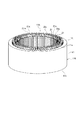
図1は本発明の実施形態に係る回転電機1のステータ10(固定子)の一例を示す分解斜視図である。図2はステータ10の一例を示す図である。詳細には、図2(a)はステータ10の一例を示す分解側面図、図2(b)はステータ10の一例を示す側面図である。
FIG. 1 is an exploded perspective view showing an example of a stator 10 (stator) of a rotating
回転電機1のステータ10(固定子)は、ステータコアモジュール110と、コイルのコイルエンド部を絶縁体モールド成形した1つ又は2つのモールドエンドを有する。本実施形態では、ステータコア11は2つのモールドエンド30,40を有し、モールドエンド30とモールドエンド40の間にステータコアモジュール110を配置した構造を有する。
A stator 10 (stator) of the rotating
ステータコアモジュール110は、ステータコア11を有する。ステータコア11は、中央部に軸方向に沿って孔部11hを備える円筒形状に形成されており、内周部近傍に複数のスロット11aが形成されている。このスロット11aには、コイルの直線導体部21の一部分21tが配置されている。
また、ステータコアモジュール110の直線導体部21は、ステータコア11の端部11t(上端部)からモールドエンド30側に突出して配置される導体端部に接合部21aを備え、ステータコア11の端部11b(下端部)からモールドエンド40側に突出して配置される導体端部に接合部21bを備える。
The
Further, the
モールドエンド30は、ステータコアモジュール110の上部(図1の上部)に配置されている。モールドエンド30は、コイルのコイルエンド部23の曲線導体部23cを、樹脂などの絶縁体31により絶縁体モールド成形して形成されている。このモールドエンド30は、円筒形状に形成されており、詳細には、端部31t(上端部)の中央部から端部31b(下端部)の中央部へ軸方向に沿って孔部31hを備える。
モールドエンド30のコイルエンド部23は、モールドエンド30の絶縁体31の端部31b(下端部)からステータコアモジュール110側に突出して配置される導体端部に接合部23aを備える。このモールドエンド30の接合部23aは、ステータコアモジュール110の接合部21aに接合される。
The
The
本実施形態では、接合部23aの近傍には、紙などの板状の絶縁体71(70)が設けられている。この絶縁体71(70)は、各接合部溶着時の熱遮断部材や隣接するコイルとの間の電気的遮断部材として機能する。詳細には、絶縁体モールドとしての絶縁体71(70)の上端部71aは、樹脂などの絶縁体31の端部31b(下端部)付近に埋設され、絶縁体71(70)の端部71b(下端部)は、接合部23aよりもステータコアモジュール110側に突出するように設けられている。尚、絶縁体71(70)は絶縁体31(41)と同じ材料で一体成型してもよい。
In the present embodiment, a plate-like insulator 71 (70) such as paper is provided in the vicinity of the
モールドエンド40は、ステータコアモジュール110の下部(図1の下部)に配置されている。モールドエンド40は、コイルのコイルエンド部24の曲線導体部24cを、樹脂などの絶縁体41により絶縁体モールド成形して形成されている。このモールドエンド40は、円筒形状に形成されており、詳細には、端部41a(上端部)の中央部から端部41b(下端部)の中央部へ軸方向に沿って孔部41hを備える。
モールドエンド40のコイルエンド部24は、モールドエンド40の絶縁体41の端部41a(上端部)からステータコアモジュール110側に突出して配置される導体端部に接合部24aを備える。このモールドエンド40の接合部24aは、ステータコアモジュール110の接合部21bに接合される。
本実施形態では、接合部24aの近傍には、紙などの板状の絶縁体72(70)が設けられている。この紙などの絶縁体72(70)は、各接合部溶着時の熱遮断部材や隣接するコイルとの間の電気的遮断部材として機能する。詳細には、絶縁体モールドとしての絶縁体72(70)の下端部72aは、樹脂などの絶縁体41の端部41a(上端部)付近に埋設され、絶縁体72(70)の端部72b(上端部)は、接合部24aよりもステータコアモジュール110側に突出するように設けられている。尚、絶縁体72(70)は絶縁体41と同じ材料で一体成型してもよい。
The
The
In the present embodiment, a plate-like insulator 72 (70) such as paper is provided in the vicinity of the
また、本実施形態では、モールドエンド40の絶縁体41の端部41b(下端部)から、コイルに電気的に接続された複数の端子9が突出して配置されている。
In the present embodiment, a plurality of terminals 9 electrically connected to the coil are arranged so as to protrude from the
モールドエンド30の孔部31h、ステータコアモジュール110の孔部11h、モールドエンド40の孔部41hには、回転電機の回転子(不図示)が配置される。
A rotor (not shown) of the rotating electrical machine is disposed in the
ステータ10の製造方法の一例を説明する。
分布巻きコイルのコイルエンド部の導線部分を樹脂などの絶縁体により絶縁体モールド成形によりモジュール化して、モールドエンド30、モールドエンド40を作製する。コイルの直線導体部の一部分をスロットに配置したステータコア11を備えたステータコアモジュール110を作製する。
An example of a method for manufacturing the
The lead wire portion of the coil end portion of the distributed winding coil is modularized by insulator molding with an insulator such as resin, and the
次に、モールドエンド40の接合部24aと、ステータコアモジュール110の接合部21bを溶着により接合する。そして、モールドエンド30の接合部23aと、ステータコアモジュール110の接合部21aを溶着により接合する。
上記溶着時、紙などの絶縁体71が接合部23a、接合部21aの近傍に配置され、紙などの絶縁体72が接合部24a、接合部21bの近傍に配置された状態で各接合部が溶着される。各接合部が接合された場合、コイル群20が形成される。
Next, the joining
At the time of the above-mentioned welding, the
次に、ステータコアモジュール110の構成の一例について詳細に説明する。
図3はステータコアモジュール110の一例を示す斜視図である。図4はステータコアモジュール110の一例を示す平面図である。
ステータコア11は、円筒形状に形成され中央部に孔部11hを備え、内周部近傍に軸方向に貫通する複数のスロット11aを有する。このスロット11aは、ステータコア11の内周の周方向に沿って規定の間隔で形成されている。また、このスロット11aは、径方向に放射状に形成されている。
このスロット11aには、コイルの一部分を構成する断面矩形状である平角線(平角状の断面)の直線導体部21が挿通され保持されている。詳細には、各スロット11aには、内周側と外周側にそれぞれ直線導体部21が設けられている。
内周側および外周側の直線導体部21の端部の接合部21aは、ステータコア11の端部から突出して配置されており、各接合部21aの間に隙間21gが形成されている。
Next, an example of the configuration of the
FIG. 3 is a perspective view showing an example of the
The
In this
The
また、本実施形態では、ステータコア11に72個のスロット11a(溝)が形成されており、8極巻線が形成される。この場合、所定のスロットに配置された外周側直線導体部の接合部21mと、9つのスロットをまたいだ位置のスロットに配置された内周側直線導体部の接合部21nとが、モールドエンド30の導体により電気的に接合される。
Further, in the present embodiment, 72
尚、ステータは、この形態に限られるものではない。例えば、ステータコア11にX個のスロット11a(溝)が形成され、N極巻線が形成され、M個のスロット11aをまたいで連結される態様であってもよい。
The stator is not limited to this form. For example, the
ステータコア11の下端側についても同様に、内周側および外周側の直線導体部21の端部の接合部がステータコアの端部から突出して設けられており、各接合部の間に隙間が形成されている。
Similarly, on the lower end side of the
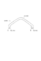
次に、モールドエンドの構成の一例について詳細に説明する。図5はモールドエンドの導体部の一例を示す図である。図6はモールドエンドの一例を示す図である。
モールドエンド30(40)は、コイルのコイルエンド部23(24)の複数の導体部を樹脂などの絶縁体31(41)で絶縁体モールド成形して形成される。樹脂などの絶縁体31(41)は、円筒形状に形成され内部に孔部31h(41h)が形成されている。
コイルのコイルエンド部は、図5に示したように、曲線導体部23c(24c)を有し、この曲線導体部23c(24c)の導体端部に接合部23a(24a)が形成されている。
Next, an example of the configuration of the mold end will be described in detail. FIG. 5 is a view showing an example of the conductor portion of the mold end. FIG. 6 is a diagram illustrating an example of a mold end.
The mold end 30 (40) is formed by subjecting a plurality of conductor portions of the coil end portion 23 (24) of the coil to insulator molding with an insulator 31 (41) such as resin. The insulator 31 (41) such as resin is formed in a cylindrical shape and has a
As shown in FIG. 5, the coil end portion of the coil has a
本実施形態では、曲線導体部23c(24c)は断面円形状に形成されているが、断面矩形状に形成されていてもよい。接合部23a(24a)は、断面矩形状に形成されている。各接合部23a(24a)は、ステータコアモジュール110の接合部に対応する位置にそれぞれ配置されている。詳細には、接合部23a(24a)は、円筒状の絶縁体31(41)の内周の周方向に沿って規定の間隔で、内周側および外周側に2列に配置されている。
In the present embodiment, the
詳細には、コイルエンド部23(24)の一方の接合部Mは外周側に配置され、他方の接合部Nは内周側に配置され、曲線導体部23c(24c)により電気的に接続されている。本実施形態では、曲線導体部23c(24c)の接合部Nは、外周側の所定位置に配置された接合部Mを基準として周方向に9ステップ隣の位置の内周側に位置している。尚、接合部Nと接合部Mの位置は、コイルの巻線の態様に応じて規定される。
Specifically, one joint portion M of the coil end portion 23 (24) is disposed on the outer peripheral side, and the other joint portion N is disposed on the inner peripheral side, and is electrically connected by the
周方向に沿って配置された内周側の接合部と、外周側の接合部の間には、円筒形状の紙などの絶縁体70(71、72)が設けられている。溶着接合時、この円筒形状の絶縁体70(71、72)は、ステータコアモジュール110の内周側および外周側の直線導体部21の接合部21aの間の隙間21gに配置される。このように、ステータコアモジュール110およびモールドエンド30(40)の内周側に配置された各接合部と、ステータコアモジュール110およびモールドエンド30(40)の外周側に配置された各接合部の間に円筒形状の絶縁体70(71、72)が配置される。
An insulator 70 (71, 72) such as cylindrical paper is provided between an inner peripheral side joint portion arranged along the circumferential direction and an outer peripheral side joint portion. At the time of welding and bonding, the cylindrical insulators 70 (71, 72) are disposed in a
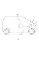
図7は本発明の実施形態に係る回転電機を備えた車両の一例を説明するための概念図である。回転電機1(1A)は、上記コイルをステータコアに分布巻きに配置したステータ(固定子)、回転子(不図示)などを有する。車両100は、回転電機1を備える。詳細には、図7に示した車両100は、エンジン51、鉛バッテリなどの第1のバッテリ52、必要に応じて搭載されるリチウムイオンバッテリなどの第2のバッテリ53、回転電機1(1A)などを有する。エンジン51と回転電機1(1A)の回転子はベルトなどの動力伝達手段を介して動力を伝達可能に接続されている。第1のバッテリ52、第2のバッテリ53は、回転電機1(1A)と電気的に接続されている。
FIG. 7 is a conceptual diagram for explaining an example of a vehicle including the rotating electrical machine according to the embodiment of the present invention. The rotating electrical machine 1 (1A) includes a stator (stator), a rotor (not shown), and the like in which the coils are arranged in a distributed winding around a stator core. The
本実施例では、回転電機1(1A)は、モータ機能付き発電機として使用される。ステータが小型であるので、回転電機1(1A)も小型である。回転電機1(1A)はエンジンの動力により回転子を回転して発電し、バッテリを短時間でチャージする。また、エンジン51を始動(再始動)時に、回転電機1(1A)は高出力のスタータとして機能する。また、車両加速時に、回転電機1(1A)は、エンジン51をモータアシストする。
尚、車両100や回転電機1(1A)は、上記実施形態に限られるものではない。
In this embodiment, the rotating electrical machine 1 (1A) is used as a generator with a motor function. Since the stator is small, the rotating electrical machine 1 (1A) is also small. The rotating electrical machine 1 (1A) rotates the rotor with the power of the engine to generate power, and charges the battery in a short time. Further, when the
The
以上、説明したように、本発明の実施形態に係るステータ10は、回転電機1のステータコア11に分布巻きで配線されるコイルを有する。本実施形態では、ステータ10は、複数のコイルからなるコイル群20を有する。ステータ10は、コイルの直線導体部21の一部分をスロット11aに配置したステータコア11を備えたステータコアモジュール110と、コイルのエンド部を絶縁体モールド成形したモールドエンド30(40)と、を有する。
ステータコアモジュール110の直線導体部21は、ステータコア11からモールドエンド30(40)側に突出して配置される導体端部に第1の接合部としての接合部21a(21b)を備える。モールドエンド30(40)のコイルエンド部は、絶縁体モールドの端部からステータコアモジュール110側に突出して配置される導体端部に第2の接合部としての接合部23a(24a)を備える。ステータ10は、第1の接合部としての接合部21a(21b)と第2の接合部としての接合部23a(24a)を接合した構造を有する。
このため、簡単な構造のステータを提供することができる。また、モールドエンド30(40)のコイルエンド部は簡単な構造を有するので、コイルエンド部を小型に形成することができ、ステータが小型である。
As described above, the
The
For this reason, a stator having a simple structure can be provided. Moreover, since the coil end part of the mold end 30 (40) has a simple structure, the coil end part can be formed in a small size, and the stator is small.
また、本発明の実施形態に係るステータの製造方法は、ステータコアモジュールの第1の接合部と、モールドエンド30(40)のコイルエンド部の第2の接合部とを溶着により接合する工程を有する。この接合は、ロウ付け、TIG溶接などの所定の溶着方式で接合してもよい。TIG溶接は、非溶極式のイナートガスアーク溶接であり、電極にはタングステンまたはタングステン合金を使用し、シールドガスにアルゴンガスなどを用いて、アークおよび溶融金属を空気より遮断保護しながら溶接を行う。また、溶着の加熱源はレーザーなどであってもよい。
このため、簡単に分布巻きのステータを製造することができる。
The stator manufacturing method according to the embodiment of the present invention includes a step of joining the first joint portion of the stator core module and the second joint portion of the coil end portion of the mold end 30 (40) by welding. . This joining may be performed by a predetermined welding method such as brazing or TIG welding. TIG welding is non-melting-type inert gas arc welding, where tungsten or tungsten alloy is used for the electrode, argon gas is used for the shielding gas, and welding is performed while protecting the arc and molten metal from air. . The heat source for welding may be a laser or the like.
For this reason, a distributed winding stator can be manufactured easily.
また、本発明の実施形態では、モールドエンドの複数の第2の接合部は、内周側および外周側の2列に周方向に沿って規定間隔に配置されている。モールドエンドは、内周側の第2の接合部と外周側の第2の接合部との間に円筒形状の絶縁体を有し、該円筒形状の絶縁体が、絶縁モールドの端部から第2の接合部よりもステータコアモジュール側に突出するように立設されている。
溶着接合時、この円筒形状の絶縁体70(71、72)は、ステータコアモジュール110の内周側および外周側の直線導体部21の接合部21aの間の隙間21gに配置される。このように、ステータコアモジュール110およびモールドエンド30(40)の内周側に配置された各接合部と、ステータコアモジュール110およびモールドエンド30(40)の外周側に配置された各接合部の間に円筒形状の絶縁体70(71、72)が配置されるので、内周側の接合部と外周側の接合部とを熱的且つ電気的に絶縁することができる。
Further, in the embodiment of the present invention, the plurality of second joint portions of the mold end are arranged at regular intervals along the circumferential direction in two rows on the inner peripheral side and the outer peripheral side. The mold end has a cylindrical insulator between the second joint portion on the inner peripheral side and the second joint portion on the outer peripheral side, and the cylindrical insulator is connected to the second end from the end of the insulating mold. It is erected so as to protrude from the joint portion of 2 to the stator core module side.
At the time of welding and bonding, the cylindrical insulators 70 (71, 72) are disposed in a
また、本発明の実施形態に係る回転電機は、上記ステータを備える。このため、回転電機としてのモータは、小型で高出力を有する。また、回転電機としての発電機は小型で高発電力を有する。また、回転電機として、モータ機能付き発電機は、小型で高出力且つ高発電力を有する。 Moreover, the rotary electric machine which concerns on embodiment of this invention is provided with the said stator. For this reason, the motor as a rotating electrical machine is small and has high output. A generator as a rotating electrical machine is small and has high power generation. Further, as a rotating electrical machine, a generator with a motor function has a small size, high output, and high power generation.
また、本発明の実施形態に係る車両は、上記回転電機を備える。この回転電機を発電機として使用した場合、車両への搭載スペースを小さく抑えることができ、車両に搭載のバッテリを短時間でチャージすることができる。また、回転電機をモータとして使用した場合、車両への搭載スペースを小さく抑えることができ、エンジンを始動(再始動)する高出力のスタータとして用いることができる。また、車両加速時に、エンジンをモータアシストすることで、加速性能の向上、省燃費などを実現することができる。また、回転電機をモータ機能付き発電機として使用した場合、車両への搭載スペースを小さく抑えることができ、上述した短時間でのバッテリチャージ、エンジンの始動(再始動)、車両加速時のモータアシストによる加速性能の向上、省燃費などを実現することができる。 Moreover, the vehicle which concerns on embodiment of this invention is provided with the said rotary electric machine. When this rotating electrical machine is used as a generator, the mounting space on the vehicle can be kept small, and the battery mounted on the vehicle can be charged in a short time. Moreover, when a rotary electric machine is used as a motor, the mounting space in a vehicle can be suppressed small and it can be used as a high output starter for starting (restarting) the engine. In addition, acceleration of the engine and fuel saving can be realized by assisting the engine with the motor during vehicle acceleration. In addition, when the rotating electrical machine is used as a generator with a motor function, the mounting space on the vehicle can be reduced, and the above-described battery charging in a short period of time, engine starting (restarting), and motor assist during vehicle acceleration. Acceleration performance and fuel saving can be realized.
以上、本発明の実施形態について図面を参照して詳述してきたが、具体的な構成はこれらの実施形態に限られるものではなく、本発明の要旨を逸脱しない範囲の設計の変更等があっても本発明に含まれる。
また、上述の各図で示した実施形態は、その目的及び構成等に特に矛盾や問題がない限り、互いの記載内容を組み合わせることが可能である。
また、各図の記載内容はそれぞれ独立した実施形態になり得るものであり、本発明の実施形態は各図を組み合わせた一つの実施形態に限定されるものではない。
As described above, the embodiments of the present invention have been described in detail with reference to the drawings. However, the specific configuration is not limited to these embodiments, and there are design changes and the like without departing from the gist of the present invention. Is included in the present invention.
Further, the embodiments described in the above drawings can be combined with each other as long as there is no particular contradiction or problem in the purpose and configuration.
Moreover, the description content of each figure can become independent embodiment, respectively, and embodiment of this invention is not limited to one embodiment which combined each figure.
1…回転電機
10…ステータ(固定子)
11…ステータコア
11a…スロット
21…直線導体部
23…コイルエンド部
23a…接合部
23c…曲線導体部
24…コイルエンド部
24a…接合部
24c…曲線導体部
30…モールドエンド
31…絶縁体
40…モールドエンド
70,71,72…絶縁体
100…車両
110…ステータコアモジュール
DESCRIPTION OF
DESCRIPTION OF
Claims (5)
前記コイルの直線導体部の一部分をスロットに配置したステータコアを備えたステータコアモジュールと、
前記コイルのコイルエンド部を絶縁体モールド成形したモールドエンドと、を有し、
前記ステータコアモジュールの前記直線導体部は、前記ステータコアから前記モールドエンド側に突出して配置される導体端部に第1の接合部を備え、
前記モールドエンドの前記コイルエンド部は、絶縁体モールドの端部からステータコアモジュール側に突出して配置される導体端部に第2の接合部を備え、
前記第1の接合部と前記第2の接合部を接合した構造を有することを特徴とする
ステータ。 A stator comprising a coil wired in a distributed winding to a stator core of a rotating electrical machine,
A stator core module including a stator core in which a part of the linear conductor portion of the coil is disposed in the slot;
A mold end formed by insulating molding the coil end portion of the coil,
The linear conductor portion of the stator core module includes a first joint portion at a conductor end portion that protrudes from the stator core toward the mold end side,
The coil end portion of the mold end includes a second joint portion at a conductor end portion that protrudes from the end portion of the insulator mold to the stator core module side,
A stator having a structure in which the first joint and the second joint are joined.
前記モールドエンドは、内周側の第2の接合部と外周側の第2の接合部との間に円筒形状の絶縁体を有し、
前記円筒形状の絶縁体は、絶縁モールドの端部から第2の接合部よりも前記ステータコアモジュール側に突出するように立設されていることを特徴とする請求項1に記載のステータ。 The plurality of second joint portions of the mold end are arranged at regular intervals along the circumferential direction in two rows on the inner peripheral side and the outer peripheral side,
The mold end has a cylindrical insulator between the second joint portion on the inner peripheral side and the second joint portion on the outer peripheral side,
2. The stator according to claim 1, wherein the cylindrical insulator is erected so as to protrude from the end portion of the insulating mold to the stator core module side than the second joint portion.
前記ステータは、前記コイルの直線導体部の一部分をスロットに配置したステータコアを備えたステータコアモジュールと、前記コイルのコイルエンド部を絶縁体モールド成形したモールドエンドと、を有し、
前記ステータコアモジュールの前記直線導体部は、前記ステータコアから前記モールドエンド側に突出して配置される導体端部に第1の接合部を備え、
前記モールドエンドの前記コイルエンド部は、絶縁体モールドの端部からステータコアモジュール側に突出して配置される導体端部に第2の接合部を備え、
前記第1の接合部と前記第2の接合部を溶着により接合する工程を有することを特徴とする
ステータの製造方法。 A stator manufacturing method comprising a coil wired in a distributed winding to a stator core of a rotating electrical machine,
The stator includes a stator core module including a stator core in which a part of a linear conductor portion of the coil is disposed in a slot, and a mold end in which a coil end portion of the coil is molded by an insulator.
The linear conductor portion of the stator core module includes a first joint portion at a conductor end portion that protrudes from the stator core toward the mold end side,
The coil end portion of the mold end includes a second joint portion at a conductor end portion that protrudes from the end portion of the insulator mold to the stator core module side,
A method of manufacturing a stator, comprising a step of joining the first joint and the second joint by welding.
Priority Applications (3)
| Application Number | Priority Date | Filing Date | Title |
|---|---|---|---|
| JP2015056927A JP2016178783A (en) | 2015-03-19 | 2015-03-19 | Stator, rotary electric machine, vehicle, and manufacturing method of stator |
| CN201610127297.7A CN105990917A (en) | 2015-03-19 | 2016-03-07 | Stator, rotating electric machine, vehicle, and stator manufacturing method |
| US15/074,648 US20160276887A1 (en) | 2015-03-19 | 2016-03-18 | Stator, rotating electric machine, vehicle, and stator manufacturing method |
Applications Claiming Priority (1)
| Application Number | Priority Date | Filing Date | Title |
|---|---|---|---|
| JP2015056927A JP2016178783A (en) | 2015-03-19 | 2015-03-19 | Stator, rotary electric machine, vehicle, and manufacturing method of stator |
Publications (1)
| Publication Number | Publication Date |
|---|---|
| JP2016178783A true JP2016178783A (en) | 2016-10-06 |
Family
ID=56925880
Family Applications (1)
| Application Number | Title | Priority Date | Filing Date |
|---|---|---|---|
| JP2015056927A Pending JP2016178783A (en) | 2015-03-19 | 2015-03-19 | Stator, rotary electric machine, vehicle, and manufacturing method of stator |
Country Status (3)
| Country | Link |
|---|---|
| US (1) | US20160276887A1 (en) |
| JP (1) | JP2016178783A (en) |
| CN (1) | CN105990917A (en) |
Cited By (2)
| Publication number | Priority date | Publication date | Assignee | Title |
|---|---|---|---|---|
| JP2019126153A (en) * | 2018-01-15 | 2019-07-25 | トヨタ自動車株式会社 | Stator of rotary electric machine and method for manufacturing stator coil |
| JP2020078202A (en) * | 2018-11-09 | 2020-05-21 | アイシン・エィ・ダブリュ株式会社 | Armature and manufacturing method thereof |
Families Citing this family (8)
| Publication number | Priority date | Publication date | Assignee | Title |
|---|---|---|---|---|
| US9825513B2 (en) * | 2014-06-09 | 2017-11-21 | Nissan Motor Co., Ltd. | Rectangular wire stator coil manufacturing method |
| JP6364465B2 (en) | 2016-12-09 | 2018-07-25 | 本田技研工業株式会社 | Slot coil and stator of rotating electric machine |
| WO2019073724A1 (en) * | 2017-10-11 | 2019-04-18 | 日立オートモティブシステムズ株式会社 | Stator for dynamo-electric machine |
| US11451120B2 (en) * | 2017-11-30 | 2022-09-20 | Aisin Corporation | Method of manufacturing armature |
| DE102018214081A1 (en) * | 2018-08-21 | 2020-02-27 | Bayerische Motoren Werke Aktiengesellschaft | Stator for an electrical machine |
| US10992212B2 (en) * | 2018-10-31 | 2021-04-27 | GM Global Technology Operations LLC | Method of manufacturing a stator |
| US11095197B2 (en) * | 2018-10-31 | 2021-08-17 | GM Global Technology Operations LLC | Modular stator |
| DE102018131960A1 (en) * | 2018-12-12 | 2020-06-18 | Thyssenkrupp Ag | Stator, electrical machine and manufacturing method |
Citations (5)
| Publication number | Priority date | Publication date | Assignee | Title |
|---|---|---|---|---|
| US20040100157A1 (en) * | 2001-02-22 | 2004-05-27 | Delco Remy America | Electric machine end turn connectors |
| JP2006141076A (en) * | 2004-11-10 | 2006-06-01 | Toyota Motor Corp | Stator structure |
| JP2006158044A (en) * | 2004-11-26 | 2006-06-15 | Toyota Motor Corp | Stator structure |
| JP2010239798A (en) * | 2009-03-31 | 2010-10-21 | Aisin Aw Co Ltd | Armature for rotary electric machine |
| JP2014100038A (en) * | 2012-11-16 | 2014-05-29 | Hitachi Automotive Systems Ltd | Stator of rotary electric machine |
-
2015
- 2015-03-19 JP JP2015056927A patent/JP2016178783A/en active Pending
-
2016
- 2016-03-07 CN CN201610127297.7A patent/CN105990917A/en active Pending
- 2016-03-18 US US15/074,648 patent/US20160276887A1/en not_active Abandoned
Patent Citations (5)
| Publication number | Priority date | Publication date | Assignee | Title |
|---|---|---|---|---|
| US20040100157A1 (en) * | 2001-02-22 | 2004-05-27 | Delco Remy America | Electric machine end turn connectors |
| JP2006141076A (en) * | 2004-11-10 | 2006-06-01 | Toyota Motor Corp | Stator structure |
| JP2006158044A (en) * | 2004-11-26 | 2006-06-15 | Toyota Motor Corp | Stator structure |
| JP2010239798A (en) * | 2009-03-31 | 2010-10-21 | Aisin Aw Co Ltd | Armature for rotary electric machine |
| JP2014100038A (en) * | 2012-11-16 | 2014-05-29 | Hitachi Automotive Systems Ltd | Stator of rotary electric machine |
Cited By (5)
| Publication number | Priority date | Publication date | Assignee | Title |
|---|---|---|---|---|
| JP2019126153A (en) * | 2018-01-15 | 2019-07-25 | トヨタ自動車株式会社 | Stator of rotary electric machine and method for manufacturing stator coil |
| US11075560B2 (en) | 2018-01-15 | 2021-07-27 | Toyota Jidosha Kabushiki Kaisha | Stator of rotary electric machine and method of manufacturing stator coil |
| JP7003674B2 (en) | 2018-01-15 | 2022-01-20 | トヨタ自動車株式会社 | Manufacturing method of stator and stator coil of rotary electric machine |
| JP2020078202A (en) * | 2018-11-09 | 2020-05-21 | アイシン・エィ・ダブリュ株式会社 | Armature and manufacturing method thereof |
| JP7172470B2 (en) | 2018-11-09 | 2022-11-16 | 株式会社アイシン | Armature and armature manufacturing method |
Also Published As
| Publication number | Publication date |
|---|---|
| US20160276887A1 (en) | 2016-09-22 |
| CN105990917A (en) | 2016-10-05 |
Similar Documents
| Publication | Publication Date | Title |
|---|---|---|
| JP2016178783A (en) | Stator, rotary electric machine, vehicle, and manufacturing method of stator | |
| JP5661161B1 (en) | Rotating electric machine | |
| JP5729091B2 (en) | Bus bar, motor and manufacturing method thereof | |
| JP6286129B2 (en) | Bus bar unit | |
| WO2018142845A1 (en) | Stator manufacturing method and motor | |
| JP6576549B2 (en) | Armature manufacturing method, rotating electrical machine manufacturing method, and armature manufacturing apparatus | |
| JP2007312560A (en) | Insulator and rotary electric machine | |
| JP2013208038A (en) | Rotary electric machine and winding mounting method | |
| US9537366B2 (en) | Magnet-type generator | |
| JPWO2019039518A1 (en) | Split core linked body and method of manufacturing armature | |
| JP2014093861A (en) | Stator and rotary electric machine | |
| JPWO2019003561A1 (en) | Rotating electric machine stator and rotating electric machine | |
| JP2005229677A (en) | Bus ring structure of motor | |
| US9537365B2 (en) | Magnet-type generator | |
| US8225484B2 (en) | Method of manufacturing stator for electric rotating machine | |
| JP2014121195A (en) | Armature and rotary electric machine equipped with the same | |
| US10236735B2 (en) | Electric conductor for coil and rotating electric machine | |
| JP2011217511A (en) | Stator for rotary electric machine and method for manufacturing the stator for the same | |
| JP6165454B2 (en) | Rotating electric machine | |
| JP5963928B1 (en) | Rotating machine wiring unit | |
| US10992212B2 (en) | Method of manufacturing a stator | |
| JP4548381B2 (en) | Insulator, rotating electric machine, manufacturing method thereof, and electric vehicle | |
| US20230006494A1 (en) | Stator comprising an interconnector | |
| JP2013005585A (en) | Commutator, rotor with commutator, and method of manufacturing rotor with commutator | |
| JPWO2016171205A1 (en) | Outer rotor type rotating electrical machine |
Legal Events
| Date | Code | Title | Description |
|---|---|---|---|
| A621 | Written request for application examination |
Free format text: JAPANESE INTERMEDIATE CODE: A621 Effective date: 20170808 |
|
| A131 | Notification of reasons for refusal |
Free format text: JAPANESE INTERMEDIATE CODE: A131 Effective date: 20180703 |
|
| A977 | Report on retrieval |
Free format text: JAPANESE INTERMEDIATE CODE: A971007 Effective date: 20180628 |
|
| A02 | Decision of refusal |
Free format text: JAPANESE INTERMEDIATE CODE: A02 Effective date: 20181225 |