JP2016177658A - Virtual input device, input method, and program - Google Patents
Virtual input device, input method, and program Download PDFInfo
- Publication number
- JP2016177658A JP2016177658A JP2015058545A JP2015058545A JP2016177658A JP 2016177658 A JP2016177658 A JP 2016177658A JP 2015058545 A JP2015058545 A JP 2015058545A JP 2015058545 A JP2015058545 A JP 2015058545A JP 2016177658 A JP2016177658 A JP 2016177658A
- Authority
- JP
- Japan
- Prior art keywords
- input device
- virtual input
- virtual
- virtual keyboard
- area
- Prior art date
- Legal status (The legal status is an assumption and is not a legal conclusion. Google has not performed a legal analysis and makes no representation as to the accuracy of the status listed.)
- Pending
Links
Images


Abstract
Description
本発明は、情報を入力するための仮想入力装置、入力方法、およびプログラムに関する。 The present invention relates to a virtual input device, an input method, and a program for inputting information.
従来より、メガネ型や頭部装着型などの情報通信端末において、視界の表示部に、外視野スルー像と重畳して、仮想キーボードを表示し、外視野カメラ映像から手指と仮想キーとの位置関係を検出し、手指が仮想キー相当位置に打鍵する姿勢動作を識別して、打鍵入力されたキーに対応する文字やコマンドを入力できるようにするとともに、入力結果を仮想表示部に表示し、入力に応じた処理を実行する技術が、特許文献1及び2に記載されている。
Conventionally, in information communication terminals such as glasses-type and head-mounted types, a virtual keyboard is displayed on the display section of the field of view, superimposed on the external view through image, and the positions of fingers and virtual keys from the external view camera image are displayed. Detecting the relationship, identifying the posture action in which the finger is keyed at the virtual key equivalent position, enabling the input of characters and commands corresponding to the key input key, and displaying the input result on the virtual display unit,
しかしながら、特許文献1及び2に記載の技術では、仮想表示するキーボードは、個人の嗜好の違いなどにより、必ずしも使いやすいものではなかった。
However, in the techniques described in
本発明は、このような状況に鑑みてなされたものであり、ユーザの所望どおりの仮想入力装置を提供することを目的とする。 SUMMARY An advantage of some aspects of the invention is that it provides a virtual input device as desired by a user.
上記目的を達成するため、本発明の一態様の仮想入力装置は、
複数の入力キーを備える仮想入力機器領域が所定の面に形成されており、前記仮想入力機器領域への操作を行うことで情報を入力する仮想入力装置であって、
前記仮想入力機器領域より広い領域を撮像する撮像手段と、
前記撮像手段によって撮像される領域内で行う所定の形状又は動作を検出する検出手段と、
前記検出手段によって検出された所定の形状又は動作に応じて仮想入力機器の仕様を設定する設定手段と、
を備えることを特徴とする。
In order to achieve the above object, a virtual input device according to an aspect of the present invention includes:
A virtual input device area having a plurality of input keys is formed on a predetermined surface, and is a virtual input device that inputs information by performing an operation on the virtual input device area,
Imaging means for imaging an area larger than the virtual input device area;
Detecting means for detecting a predetermined shape or operation performed in an area imaged by the imaging means;
Setting means for setting the specifications of the virtual input device according to the predetermined shape or operation detected by the detection means;
It is characterized by providing.
本発明によれば、ユーザが所望どおりの仮想入力装置を得ることができる。 According to the present invention, a virtual input device as desired by a user can be obtained.
以下、本発明の実施形態について、図面を用いて説明する。 Hereinafter, embodiments of the present invention will be described with reference to the drawings.
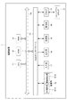
図1は、本発明の一実施形態に係る仮想入力装置のハードウェアの構成を示すブロック図である。
仮想入力装置1は、例えば、メガネ型や頭部装着型の情報通信端末として構成される。このような仮想入力装置1では、装置を装着したユーザの視界に、ユーザに提供する視界(本実施形態においては、装置を装着しない状態で見える視界)を撮影し、当該撮影した視界の映像(以下、「外視野のスルー画像」という。)と、当該外視野のスルー画像に重畳して、キーボードやテンキー等を模した仮想の入力機器(以下、「仮想キーボード」という。)を投影する。仮想入力装置1では、仮想キーボードへの所定の姿勢動作、即ち、所定の空間へのジェスチャー、(以下、単に「ジェスチャー」という。)によって、対応する入力操作が行われ、ユーザは実際にキーボードを操作しているような視覚的な体験を伴いながら、入力操作を行う。
FIG. 1 is a block diagram showing a hardware configuration of a virtual input device according to an embodiment of the present invention.
The
仮想入力装置1は、CPU(Central Processing Unit)11と、ROM(Read Only Memory)12と、RAM(Random Access Memory)13と、バス14と、入出力インターフェース15と、撮像部16と、入力部17と、出力部18と、記憶部19と、通信部20と、ドライブ21と、を備えている。
The
CPU11は、ROM12に記録されているプログラム、又は、記憶部19からRAM13にロードされたプログラムに従って各種の処理を実行する。
The
RAM13には、CPU11が各種の処理を実行する上において必要なデータ等も適宜記憶される。
The
CPU11、ROM12及びRAM13は、バス14を介して相互に接続されている。このバス14にはまた、入出力インターフェース15も接続されている。入出力インターフェース15には、撮像部16、入力部17、出力部18、記憶部19、通信部20及びドライブ21が接続されている。
The
撮像部16は、図示はしないが、光学レンズ部と、イメージセンサと、を備えている。
Although not shown, the
光学レンズ部は、被写体を撮影するために、光を集光するレンズ、例えばフォーカスレンズやズームレンズ等で構成される。
フォーカスレンズは、イメージセンサの受光面に被写体像を結像させるレンズである。ズームレンズは、焦点距離を一定の範囲で自在に変化させるレンズである。
光学レンズ部にはまた、必要に応じて、焦点、露出、ホワイトバランス等の設定パラメータを調整する周辺回路が設けられる。
The optical lens unit is configured by a lens that collects light, for example, a focus lens or a zoom lens, in order to photograph a subject.
The focus lens is a lens that forms a subject image on the light receiving surface of the image sensor. The zoom lens is a lens that freely changes the focal length within a certain range.
The optical lens unit is also provided with a peripheral circuit for adjusting setting parameters such as focus, exposure, and white balance as necessary.
イメージセンサは、光電変換素子や、AFE(Analog Front End)等から構成される。
光電変換素子は、例えばCMOS(Complementary Metal Oxide Semiconductor)型の光電変換素子等から構成される。光電変換素子には、光学レンズ部から被写体像が入射される。そこで、光電変換素子は、被写体像を光電変換(撮像)して画像信号を一定時間蓄積し、蓄積した画像信号をアナログ信号としてAFEに順次供給する。
AFEは、このアナログの画像信号に対して、A/D(Analog/Digital)変換処理等の各種信号処理を実行する。各種信号処理によって、ディジタル信号が生成され、撮像部16の出力信号として出力される。
このような撮像部16の出力信号を、以下、「撮像画像のデータ」と呼ぶ。撮像画像のデータは、CPU11や図示しない画像処理部等に適宜供給される。
The image sensor includes a photoelectric conversion element, AFE (Analog Front End), and the like.
The photoelectric conversion element is composed of, for example, a CMOS (Complementary Metal Oxide Semiconductor) type photoelectric conversion element or the like. A subject image is incident on the photoelectric conversion element from the optical lens unit. Therefore, the photoelectric conversion element photoelectrically converts (captures) the subject image, accumulates the image signal for a predetermined time, and sequentially supplies the accumulated image signal as an analog signal to the AFE.
The AFE performs various signal processing such as A / D (Analog / Digital) conversion processing on the analog image signal. Through various signal processing, a digital signal is generated and output as an output signal of the
Hereinafter, the output signal of the
このように構成される撮像部16は、仮想入力装置1の装着者(ユーザ)の視界である外視野を撮影する外視野用撮像部16−1と、仮想入力装置1の装着者の視線を検出するために用いる視線検出用撮像部16−2とを有する。なお、視線の検出については、例えば、直接目を撮影して虹彩の位置に基づいて、行ったり、赤外線LED(Light Emitting Diode)等を眼球に照射し、当該赤外線の反射光の角膜上の位置(角膜反射の位置)に対する瞳孔の位置に基づいて、行ったりする。赤外線LEDによる視線の検出の手法を用いる場合は、視線検出用撮像部16−2は、赤外線カメラにて構成する。
The
入力部17は、各種釦等で構成され、ユーザの指示操作に応じて各種情報を入力する。
The
出力部18は、ディスプレイやスピーカ等で構成され、画像や音声を出力する。また、ディスプレイで構成される出力部18は、ユーザの視界に外視野用撮像部16−1から出力された外視野のスルー画像を表示し、当該外視野のスルー画像の内容に対応して仮想キーボードを重畳表示させる。仮想入力装置1では、仮想キーボードに対するユーザの手指の姿勢動作(ジェスチャー)に対応して仮想キーボードの表示や入力処理を行うために、ユーザは、現実世界にはない仮想キーボードに対して入力操作を行っているような感覚を惹起させる。
なお、視線検出用撮像部16−2による視線の検出用の撮影や出力部18による表示は、目を直接撮影したり、直接表示させたりしてもよいが、ハーフミラー等を用いて、間接的に行うように構成してもよい。このように構成することで、撮影部分や出力部分を実際にユーザの目の前に配置する必要がなくなり機構を単純化でき、例えば、出力部分を半透過型に構成すれば実世界の視界を用いるようにすることができ、外視野の映像を表示させる必要がなくなる。
The
Note that the line-of-sight detection imaging by the line-of-sight detection imaging unit 16-2 and the display by the
記憶部19は、ハードディスク或いはDRAM(Dynamic Random Access Memory)等で構成され、各種画像のデータを記憶する。
通信部20は、インターネットを含むネットワークを介して他の装置(図示せず)との間で行う通信を制御する。
The
The
ドライブ21には、磁気ディスク、光ディスク、光磁気ディスク、或いは半導体メモリ等よりなる、リムーバブルメディア31が適宜装着される。ドライブ21によってリムーバブルメディア31から読み出されたプログラムは、必要に応じて記憶部19にインストールされる。また、リムーバブルメディア31は、記憶部19に記憶されている画像のデータ等の各種データも、記憶部19と同様に記憶することができる。
A
このように構成される仮想入力装置1では、複数種の仮想キーボードの中から所定の仮想キーボードの選択/指定(表示)し、選択した仮想キーボードへの入力/入力の取り消し、仮想キーボードの終了(非表示)等の仮想キーボードへの操作を行うことができる機能を有する。仮想キーボードへの操作とは、表示される仮想キーボードに対して、対応する所定の姿勢動作(ジェスチャー)を行うことで実現する。
また、仮想入力装置1では、仮想キーボードの選択/指定(表示)、指定した仮想キーボードに対するサイズや形状や位置の変更等の仮想キーボードの仕様の変更(仮想キーボードの種類、設定領域、形状、又はキー配列の仕様の設定)を行うことができる機能を有する。仮想キーボードの仕様の変更は、仮想キーボードの仕様に対応した所定の姿勢動作(ジェスチャー)を行うことで実現する。
In the
Further, in the
詳細には、仮想入力装置1では、仮想キーボードの動作として起動(1)・打鍵入力(2)・仕様変更(3)・終了(4)を行うことができる。
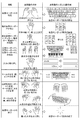
図2は、姿勢動作に応じた仮想キーボードの選択/指定(表示)や仕様の変更の対応動作の具体例について説明するための模式図である。
Specifically, the
FIG. 2 is a schematic diagram for explaining a specific example of the operation corresponding to the selection / designation (display) of the virtual keyboard and the change of the specification according to the posture operation.
(1)起動
外視野用撮像部16−1の映像(外視野のスルー画像)から、手指を検出して、ユーザの手が、机、壁、膝などの平曲面上や空間上で、打鍵(キー入力)の準備や開始を示す動作姿勢(ジェスチャー)を識別すると、仮想キーボードを出現させて起動させるUI(User interface)の処理を起動する。
仮想キーボードを起動するための所定の動作姿勢とは、例えば、以下の図2の例に示すようなものがある。
両手の各指をやや開いて、掌を下側に、眼下の左右にそろえて構えるようにしたり、両手をキーボードのニュートラル位置(ホームポジション)に構えている(各指を置く)ようにしたりする動作姿勢をする。その結果、QWERTY配列の仮想キーボードが指定されて表示される(仮想キーボード表示の開始)。
片手を手前に開いて、前(上)に出すような操作姿勢をする。その結果、携帯電話等で用いられるキー配列の仮想キーボードが指定されて表示される(仮想キーボード表示の開始)。
(1) Startup The user's hand is detected on the flat curved surface such as a desk, a wall, or a knee, or on a space by detecting a finger from the image (through-image of the external visual field) of the imaging unit for external visual field 16-1. When an action posture (gesture) indicating preparation or start of (key input) is identified, a UI (User interface) process for starting and starting a virtual keyboard is started.
The predetermined operation posture for activating the virtual keyboard is, for example, as shown in the example of FIG.
Slightly open the fingers of both hands so that the palm is placed on the lower side and the left and right sides of the eyes, or both hands are held in the neutral position (home position) of the keyboard (place each finger) Take action posture. As a result, a virtual keyboard with a QWERTY layout is designated and displayed (start of virtual keyboard display).
Open your hand and move it forward (up). As a result, a virtual keyboard having a key layout used in a mobile phone or the like is designated and displayed (start of virtual keyboard display).
(2)打鍵入力
仮想キーボードに重なったユーザの手指を、外視野カメラ映像から認識し、ユーザの手指に重なる、あるいは影となる位置の仮想キーを、隠蔽表示(や半透過表示)する。そして、仮想キーボードへの手指の打鍵を検知すると、打鍵されたキーの仮想表示を、押し下げ表示や区別確認表示する。また、入力された文字やコマンドを、仮想の入力結果表示部に表示する。その後、入力に応じた処理を実行する。
また、図2の例に示すように、片手で手の甲を手前に向けた姿勢で、手を左右に振るような動作をすることで、入力を取り消す。
(2) Keystroke input The user's finger that overlaps the virtual keyboard is recognized from the external view camera image, and the virtual key at a position that overlaps or shadows the user's finger is hidden (or translucently displayed). When a keystroke of a finger on the virtual keyboard is detected, a virtual display of the key that has been pressed is displayed in a pressed-down manner or a distinction confirmation display. In addition, the input characters and commands are displayed on a virtual input result display section. Thereafter, processing corresponding to the input is executed.
Also, as shown in the example of FIG. 2, the input is canceled by performing an operation of shaking the hand to the left and right in a posture with the back of the hand facing forward.
(3)仕様の設定
手指を使用に合わせた大きさにしたりする等の所定の姿勢動作によって仮想キーボードの仕様を設定する処理を開始する。所定の姿勢動作は、通常の打鍵入力操作であると誤認識してしまうことを防ぐために、通常の打鍵入力の時の動作では行うことのない特殊な動作を設定しておくことが望ましい。あるいは、手指の動作の他にも、例えば、通常のキーボード操作におけるショートカットキーを、予め設定しておき、その入力が検出された場合に、いずれかのモードに切り替えるようにしてもよい。
仕様の設定の例としては、(3−1)仮想キーボードの種類の選択、(3−2)仮想キーボードの形状、(3−3)仮想キーボードの拡大縮小、(3−4)仮想キーボードのキー配列があり、以下の図2の例に示すようなものがある。
(3) Specification setting The processing for setting the specification of the virtual keyboard is started by a predetermined posture operation such as making the finger size suitable for use. In order to prevent the predetermined posture movement from being erroneously recognized as a normal keystroke input operation, it is desirable to set a special movement that is not performed in the normal keystroke input movement. Alternatively, in addition to the operation of fingers, for example, shortcut keys for normal keyboard operations may be set in advance, and when the input is detected, the mode may be switched to one of the modes.
Examples of specification settings include (3-1) selection of virtual keyboard type, (3-2) shape of virtual keyboard, (3-3) enlargement / reduction of virtual keyboard, and (3-4) keys of virtual keyboard. There is an array, such as shown in the example of FIG. 2 below.
(3−1)仮想キーボードの種類の選択
片手の掌を手前に開き、片手を掌の上に1つの指(本実施形態においては、人差し指)を置くような動作姿勢をする。その結果、テンキー/電卓型(電卓キー)/電話キー(電話型)の仮想キーボードが選択される。
対応する仮想キーボードの数を示すように指で指定文字を表現する(対応する仮想キーボード表示の開始)。例えば、仮想キーボード1:QWERTY配列の仮想キーボード、仮想キーボード2:テンキーの仮想キーボード、仮想キーボード3:楽器の鍵盤の仮想キーボードが予め対応付けられており、対応する数字(1乃至3)を指で表現することで、対応する仮想キーボードが選択される(仮想キーボード表示の開始)。
(3-1) Selection of Virtual Keyboard Type The posture is such that the palm of one hand is opened and one finger (an index finger in the present embodiment) is placed on the palm. As a result, a virtual keyboard of numeric keypad / calculator type (calculator key) / telephone key (telephone type) is selected.
A designated character is expressed with a finger so as to indicate the number of corresponding virtual keyboards (start of corresponding virtual keyboard display). For example, a virtual keyboard 1: a virtual keyboard with a QWERTY layout, a virtual keyboard 2: a virtual keyboard with a numeric keypad, a virtual keyboard 3: a virtual keyboard with a musical instrument keyboard are associated in advance, and the corresponding numbers (1 to 3) are indicated with a finger. By expressing, the corresponding virtual keyboard is selected (start of virtual keyboard display).
(3−2)仮想キーボードの形状
QWERTY配列の仮想キーボードの場合には、仮想キーボードの表示状態において、ホームポジションに構えているような姿勢から、両手の幅を広げたり狭めたりすることで仮想キーボードのサイズ(キーの大きさ、幅、ピッチ)を変更する。
即ち、両手の指で囲った矩形枠を左右に開く動作と、その時の手指の縦幅と開く横の長さに応じて、大きさを決める。この際、手指の大きさ、太さ、長さを検出して、表示仕様とするデフォルトキーボードの仕様(キー配置、キーの数)とに応じて、その手指の大きさ、太さ、長さにて入力しやすいと推定されるような、適切な大きさ、形状、ピッチの仮想キーに自動的に切り替えるようにしてもよい。さらに、投影面が平坦でなく一部凹凸がある場合には、一部領域に指をかざして動作することにより、その領域の表示のみを変更することもできる。例えば、曲面上に仮想キーボードを表示する場合、両端のキーを斜めから見ると幅が狭くなってしまうが、このような場合には、両端のキーの幅を広げる動作によって、そこだけ拡大することができる。
(3-2) Shape of virtual keyboard In the case of a virtual keyboard with a QWERTY layout, the virtual keyboard is expanded or narrowed by widening or narrowing the width of both hands from a posture that is held at the home position in the display state of the virtual keyboard. Change the size (key size, width, pitch).
That is, the size is determined according to the operation of opening the rectangular frame enclosed by the fingers of both hands to the left and right, the vertical width of the fingers and the horizontal length of the fingers. At this time, the size, thickness, and length of the fingers are detected according to the default keyboard specifications (key layout, number of keys) as the display specifications. It is also possible to automatically switch to a virtual key of an appropriate size, shape, and pitch that is estimated to be easy to input. Furthermore, when the projection surface is not flat and there are some irregularities, it is possible to change only the display of the area by moving the finger over the area. For example, when displaying a virtual keyboard on a curved surface, the width of the keys at both ends will be narrowed when viewed from an angle, but in such a case, it will be enlarged by expanding the width of the keys at both ends. Can do.
(3−3)仮想キーボードの拡大・縮小
仮想キーボードの大きさを、増減や拡大縮小するよう変更して、自由に設定できる。例えば、向い合わせた両手を左右に開く、すぼめる姿勢動作等で行う。
(3-3) Enlarging / reducing the virtual keyboard The virtual keyboard can be freely set by changing the size to increase / decrease or enlarge / reduce. For example, this is performed by opening and closing both hands facing each other, or by a squeezing posture.
(3−4)キー配列
向かい合わせた両手を開く動きと軌跡から、直線状や曲線状の配列などを選択する。仮想キーボードにかざした両手を鏡面対象となるように逆方向に回転させると、仮想キーボードの中央を境に、左右半分のキーボードの向きが、それに追随するように回転する。
具体的には、QWERTY配列の仮想キーボードの場合には、仮想キーボードの表示状態において、ホームポジションに構えているような姿勢から、両手の位置を変えて、曲線状に広げたり、狭めたりすることで、各手に対応して仮想キーボードが分離すると共に、曲線配列の仮想キーボードに変更され、位置変更の度合いに応じて、仮想キーボードのサイズ(キーの大きさ、幅、ピッチ)を変更する。
仮想キーボードの中央を中心に両手を回転させると、仮想キーボード全体が回転する。具体的には、QWERTY配列の仮想キーボードの場合には、両手の相対的な位置を移動させて、互いに回転させることで、仮想キーボードの向き、位置、傾きを変更する。
また、アルファベット順、あるいは五十音順のキー配列、さらにはそれをユーザ自身にとって使いやすい配列に並び替えることもできる。
(3-4) Key arrangement A straight or curved arrangement is selected from the movement and locus of opening both hands facing each other. When both hands held over the virtual keyboard are rotated in the opposite direction so as to be mirrored, the directions of the left and right half keyboards follow the center of the virtual keyboard.
Specifically, in the case of a virtual keyboard with a QWERTY layout, in the virtual keyboard display state, the position of both hands is changed from a posture that is held at the home position, and is expanded or narrowed in a curved shape. Thus, the virtual keyboard is separated corresponding to each hand, and the virtual keyboard is changed to a curved keyboard, and the size (key size, width, pitch) of the virtual keyboard is changed according to the degree of position change.
When you rotate your hands around the center of the virtual keyboard, the entire virtual keyboard rotates. Specifically, in the case of a QWERTY virtual keyboard, the relative position of both hands is moved and rotated to change the orientation, position, and tilt of the virtual keyboard.
In addition, it is possible to rearrange the keys in alphabetical order or in Japanese alphabetical order, and further to the user-friendly layout.
(3−5)キー配置
図2には示していないが、キーを個別あるいは領域で、指や掌などによって、仮想キーボードが表示されている面をなぞるように移動させると、QWERTY配列のキーボードを独自のキー配置に変えることができる。
例えば、テンキーが仮想キーボードの左端にしたい場合、テンキー全体を掌で包み込むようにして、仮想キーボードの左側まで移動させると、本来、右端にあるテンキーを左端に配置させることができる。
(3-5) Key Arrangement Although not shown in FIG. 2, if a key is moved individually or in an area so as to trace the surface on which the virtual keyboard is displayed with a finger or a palm, a QWERTY keyboard is moved. You can change it to your own key layout.
For example, when the numeric keypad is desired to be at the left end of the virtual keyboard, the numeric keypad that is originally at the right end can be arranged at the left end by wrapping the entire numeric keypad with a palm and moving it to the left side of the virtual keyboard.
(4)終了
打鍵の終了を示す所定の姿勢動作(ジェスチャー)により、仮想キーボードの処理を終了する。
仮想キーボードを終了するための姿勢や動作とは、以下の図2の例に示すようなものがある。
片手の掌を手前にして握ったような姿勢(キーボードを閉じる姿勢動作)から、手を広げたような姿勢にする。その結果、仮想キーボードが表示から消える(仮想キーボード表示の終了)。また、キーボードを閉じる姿勢動作に続けて、掌を上に開き、空中に捨てるようにしたり霧消したりさせたりる。
また、その他にも、「さよなら」を示す動作姿勢となるように手を振ったり、両手の掌を左右から近づけて、キーボードを縮め/畳み/つぶしたり、片手の掌を閉じたり(テンキーを終了)するように構成できる。
(4) End The processing of the virtual keyboard is ended by a predetermined posture action (gesture) indicating the end of keystroke.
The posture and action for ending the virtual keyboard are as shown in the example of FIG. 2 below.
Change the posture from holding the palm of one hand toward you (the posture action that closes the keyboard) to the posture that spreads your hand. As a result, the virtual keyboard disappears from the display (end of the virtual keyboard display). In addition, following the posture action of closing the keyboard, the palm is opened up and thrown into the air or fogged.
In addition, you can wave your hand to the posture that shows “goodbye”, close the palms of both hands from the left and right, shrink / fold / collapse the keyboard, close the palm of one hand (end the numeric keypad) ) Can be configured.
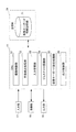
図3は、このような仮想入力装置1の機能的構成のうち、仮想キーボード入力処理を実行するための機能的構成を示す機能ブロック図である。
仮想キーボード入力処理とは、認識したジェスチャーに基づいて、仮想キーボードの開始/終了/操作/仕様変更を行う一連の処理をいう。
FIG. 3 is a functional block diagram showing a functional configuration for executing virtual keyboard input processing among the functional configurations of the
The virtual keyboard input process is a series of processes for starting / ending / operating / changing specifications of a virtual keyboard based on a recognized gesture.
仮想キーボード入力処理を実行する場合には、図3に示すように、CPU11において、撮像制御部51と、手指検出処理部52と、入力管理部53と、ジェスチャー認識部54と、仮想キーボード設定処理部55と、出力制御部56と、が機能する。
また、記憶部19の一領域には、仮想キーボード情報記憶部71が設定される。
仮想キーボード情報記憶部7には、仮想キーボードの画像や仮想キーボードの設定に関する情報(以下、「仮想キーボード情報」という。)が記憶される。具体的には、仮想キーボード情報記憶部71には、図2の例に示すような姿勢動作(ジェスチャー)に対応した仮想キーボード情報が記憶される。
When executing the virtual keyboard input process, as shown in FIG. 3, in the
A virtual keyboard information storage unit 71 is set in one area of the
The virtual keyboard
撮像制御部51は、撮影を行うように外視野用撮像部16−1を制御する。その結果、外視野用撮像部16−1では、仮想キーボード設定領域を含む外視野の撮影が行われ、外視野のスルー画像が出力される。
The
手指検出処理部52は、外視野用撮像部16−1から出力されたスルー画像を取得し、取得した外視野のスルー画像から、仮想キーボードを操作する人の手指を含む画像(以下、「手指画像」という。)を検出する。手指画像の検出は、画像認識や肌色物体を特定することで行う。
また、手指検出処理部52は、検出された手指画像において、各指の位置の検出と、掌の重心位置の検出を行う。各指の位置の検出と、掌の重心位置の検出に際して、手指検出処理部52は、より精度の高い検出を行うために、手指画像における手指の背景画像や手指以外の画像の除去を行う。また、手指検出処理部52は、手指画像を各手に分離する(両手画像の分離)。
さらに、手指検出処理部52は、各指単位での指先の位置や掌の重心位置検出を可能にするために各手における手指の輪郭抽出または、指を骨格として特定する骨格化(細線化)処理を行う。各指の位置の検出と、掌の重心位置の検出は、手指の輪郭または骨格化(細線化)された手指の形状から行う。
The finger
In addition, the finger
Further, the finger
入力管理部53は、設定フラグを用いて仮想キーボードの入力の開始や終了を管理する。
The
ジェスチャー認識部54は、手指の所定の姿勢動作として、手指の形状の変化、位置の変化、動作速度を検出し、手指検出処理部52によって検出された手の各指先の位置や掌の重心位置に基づいて、手指画像における手指の位置や姿勢動作(ジェスチャー)を認識する。
ジェスチャー認識部54によって認識される姿勢動作(ジェスチャー)は、具体的には、図2の例に示すような仮想キーボードの入力の開始や終了の姿勢動作(ジェスチャー)、キー押し動作(打鍵)の姿勢動作(ジェスチャー)、仮想キーボードの仕様変更のジェスチャー等の各種姿勢動作(ジェスチャー)である。
The
Specifically, the posture movement (gesture) recognized by the
仮想キーボード設定処理部55は、仮想キーボードの入力の開始のジェスチャーが認識された場合には、画像を解析して、両手の掌の位置・幅、各手の指先の位置、ピッチを計測して、掌や指先の位置に応じたサイズの仮想キーボードを設定する。仮想キーボードの設定は、仮想キーボード情報記憶部71に仮想キーボード情報として記憶される。
また、仮想キーボード設定処理部55は、キー押し動作のジェスチャーが認識された場合には、キーの打鍵/離鍵に応じて、キー入力処理を実行する。その結果、対応するキーの入力が行われる。
また、仮想キーボード設定処理部55は、仮想キーボードの仕様の変更のジェスチャーであった場合には、仮想キーボードの仕様の変更のジェスチャーの態様に応じて、ジェスチャーに対応するキー仕様(英字キー/カナキー/10キー/電話キー等)に変更する。
また、仮想キーボード設定処理部55は、仮想キーボードの位置、向き、サイズの変更のジェスチャー認識された場合には、仮想キーボードの位置、向き、サイズの変更のジェスチャーの態様に応じて、ジェスチャーに対応する位置、向き、サイズに変更する。
The virtual keyboard
The virtual keyboard
In addition, when the virtual keyboard
In addition, the virtual keyboard
出力制御部56は、仮想キーボード情報記憶部71に記憶される仮想キーボード情報に基づいて、仮想キーボードを表示出力するように出力部18を制御する。
具体的には、出力制御部56は、仮想キーボード設定処理部55によって設定された仮想キーボード情報に基づいて、仮想キーボードを掌、指先の位置に応じた位置に配置するように外視野のスルー画像に重ねた状態で、仮想表示を行うように出力部18を制御する。また、出力制御部56は、認識されたジェスチャーに基づいて、仮想キーボードの表示を終了して仮想キーボードを消去するように出力部18を制御する。
また、出力制御部56は、認識されたジェスチャーに基づいて、対応する仮想キーボードに変更する表示するように出力部18を制御する。
The
Specifically, the
Further, the
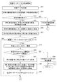
図4乃至図6は、図3の機能的構成を有する図1の仮想入力装置1が実行する仮想キーボード入力処理の流れを説明するフローチャートである。
仮想キーボード入力処理は、ユーザによる入力部17への仮想キーボード入力処理開始の操作により開始される。仮想キーボード入力処理が開始されることにより、撮像制御部51は、撮影を行うように外視野用撮像部16−1を制御する。その結果、外視野用撮像部16−1では、外視野である仮想キーボード設定領域を含む外視野の撮影が行われ、外視野のスルー画像が出力される。
4 to 6 are flowcharts for explaining the flow of the virtual keyboard input process executed by the
The virtual keyboard input process is started by an operation of starting a virtual keyboard input process to the
ステップS11において、手指検出処理部52は、外視野用撮像部16−1から取得した外視野を撮影した映像データである外視野のスルー画像を取得する。
In step S <b> 11, the finger
ステップS12において、手指検出処理部52は、手指検出処理部52によって取得された外視野のスルー画像を解析して、対象の画像認識または肌色物体の特定を行い、手指画像を検出する。
In step S12, the finger
ステップS13において、手指検出処理部52は、手指画像が検出されたか否かを判定する。
手指画像が検出されなかった場合には、ステップS13においてNOと判定されて、処理はステップS14に進む。
In step S13, the finger
If no finger image is detected, NO is determined in step S13, and the process proceeds to step S14.
ステップS14において、CPU11は、その他の画像認識処理を実行する。その後、仮想キーボード入力処理は終了する。
In step S14, the
これに対して、手指画像が検出された場合には、ステップS13においてYESと判定されて、処理はステップS15に進む。 On the other hand, if a finger image is detected, YES is determined in step S13, and the process proceeds to step S15.
ステップS15において、手指検出処理部52は、手指のジェスチャーの検出を容易にするために、ジェスチャー検出の前処理として、手指画像における背景画像の除去、手指以外の画像の除去し、両手画像の分離する処理を実行する。
In step S15, the finger
ステップS16において、手指検出処理部52は、手指のジェスチャーの検出を容易にするために、ジェスチャー検出の前処理として、手指画像における手指の輪郭抽出、または骨格化(細線化)処理を実行する。
In step S <b> 16, the finger
ステップS17において、手指検出処理部52は、手指のジェスチャーの検出を容易にするために、ジェスチャー検出の前処理として、手指画像における手の各指先の位置の検出、掌の重心位置を検出する。
In step S <b> 17, the finger
ステップS18において、入力管理部53は、仮想キーボード入力中であるか否かを判定する。入力管理部53は、現在の設定が[FLAG=0]の場合には、仮想キーボード入力中でないと判定し、現在の設定が[FLAG=1]の場合には、仮想キーボード入力中であると判定する。
仮想キーボード入力中である場合には、ステップS18においてNOと判定されて、処理はステップS41に進む。ステップS41以降の処理は後述する。
これに対して、仮想キーボード入力中でない場合には、ステップS18においてYESと判定されて、処理はステップS19に進む。
In step S18, the
If the virtual keyboard is being input, NO is determined in step S18, and the process proceeds to step S41. The processing after step S41 will be described later.
On the other hand, if the virtual keyboard is not being input, YES is determined in step S18, and the process proceeds to step S19.
ステップS19において、ジェスチャー認識部54は、手指画像を解析して、手指によるジェスチャー認識を行う。
In step S19, the
ステップS20において、ジェスチャー認識部54は、ジェスチャー認識の結果、認識されたジェスチャーが仮想キーボード入力開始のジェスチャーが検出されたか否かを判定する。
仮想キーボード入力開始のジェスチャーでなかった場合には、ステップS20においてNOと判定されて、処理はステップS24に進む。
In step S <b> 20, the
If it is not a virtual keyboard input start gesture, NO is determined in step S20, and the process proceeds to step S24.
ステップS24において、CPU11は、その他のジェスチャー検出処理を実行する。その後、ジェスチャーに対応する処理が実行されることになる。その後、仮想キーボード入力処理は終了する。
In step S24, the
これに対して、仮想キーボード入力開始のジェスチャーであった場合には、ステップS20においてYESと判定されて、処理はステップS21に進む。 On the other hand, if the gesture is a virtual keyboard input start gesture, YES is determined in step S20, and the process proceeds to step S21.
ステップS21において、仮想キーボード設定処理部55は、手指画像を解析して、掌の位置・幅、指先の位置・ピッチを計測する。仮想キーボード設定処理部55は、計測結果に基づいて、キーボードのサイズやキートップのピッチを設定する。
In step S21, the virtual keyboard
ステップS22において、出力制御部56は、仮想キーボード設定処理部55によって設定されたキーボードを掌、指先の位置に応じた位置に、指先の幅、ピッチに応じたサイズの仮想キーボードを外視野映像(外視野のスルー画像)に重ねて仮想表示を行うように出力部18を制御する。
In step S22, the
ステップS23において、入力管理部53は、仮想キーボードの入力中でない[FLAG=0]から、仮想キーボードの入力中となる[FLAG=1]にセットする。その後、処理はステップS41に進む。
In step S <b> 23, the
ステップS41おいて、ジェスチャー認識部54は、ジェスチャー認識の結果、認識されたジェスチャーが仮想キーボード入力終了のジェスチャーが検出されたか否かを判定する。
仮想キーボード入力終了のジェスチャーでなかった場合には、ステップS41においてNOと判定されて、処理はステップS44に進む。ステップS44以降の処理は後述する。
仮想キーボード入力終了のジェスチャーであった場合には、ステップS41においてYESと判定されて、処理はステップS42に進む。
In step S41, the
If it is not a virtual keyboard input end gesture, NO is determined in step S41, and the process proceeds to step S44. The processing after step S44 will be described later.
If it is a gesture for ending virtual keyboard input, YES is determined in step S41, and the process proceeds to step S42.
ステップS42において、出力制御部56は、仮想キーボードの表示を終了して仮想キーボードを消去するように出力部18を制御する。
In step S42, the
ステップS43において、入力管理部53は、仮想キーボードの入力中である[FLAG=1]から、仮想キーボードの入力中でない[FLAG=0]にセットする。その後、仮想キーボード入力処理を終了する。
In step S43, the
ステップS44において、ジェスチャー認識部54は、ジェスチャー認識の結果、認識されたジェスチャーがキー押し動作のジェスチャーであったか否かを判定する。
キー押し動作のジェスチャーでなかった場合には、ステップS44においてNOと判定されて、処理はステップS61に進む。ステップS61以降の処理については後述する。
キー押し動作のジェスチャーであった場合には、ステップS44においてYESと判定されて、処理はステップS45に進む。
In step S44, the
If it is not a key pressing gesture, NO is determined in step S44, and the process proceeds to step S61. The processing after step S61 will be described later.
If the gesture is a key press operation, YES is determined in step S44, and the process proceeds to step S45.
ステップS45において、仮想キーボード設定処理部55は、キーの打鍵/離鍵に応じて、キー入力処理を実行する。
In step S <b> 45, the virtual keyboard
ステップS46において、出力制御部56は、キーの打鍵/離鍵に応じたキー画像の変更表示を行うように出力部18を制御する。その後、仮想キーボード入力処理を終了する。
In step S <b> 46, the
ステップS61において、ジェスチャー認識部54は、ジェスチャー認識の結果、仮想キーボードの仕様の変更のジェスチャーが検出されたか否かを判定する。
仮想キーボードの仕様の変更のジェスチャーでない場合には、ステップS61においてNOと判定されて、処理はステップS64に進む。ステップS64以降の処理は後述する。
仮想キーボードの仕様の変更のジェスチャーである場合には、ステップS61においてYESと判定されて、処理はステップS62に進む。
In step S61, the
If it is not a gesture for changing the specification of the virtual keyboard, NO is determined in step S61, and the process proceeds to step S64. The processing after step S64 will be described later.
If the gesture is a change in the specification of the virtual keyboard, YES is determined in step S61, and the process proceeds to step S62.
ステップS62において、仮想キーボード設定処理部55は、仮想キーボードの仕様の変更のジェスチャーの態様に応じて、ジェスチャーに対応するキー仕様(英字キー/カナキー/10キー/電話キー等)に変更する。
In step S62, the virtual keyboard
ステップS63において、出力制御部56は、仮想キーボード設定処理部55によって変更されたキー仕様の仮想キーボードに変更表示するように出力部18を制御する。
In step S <b> 63, the
ステップS64において、ジェスチャー認識部54は、ジェスチャー認識の結果、認識されたジェスチャーが仮想キーボードの位置、向き、サイズの変更のジェスチャーが検出されたか否かを判定する。
仮想キーボードの位置、向き、サイズの変更のジェスチャーでない場合には、ステップS64においてNOと判定されて、処理はステップS65に進む。
In step S <b> 64, the
If it is not a gesture for changing the position, orientation, and size of the virtual keyboard, NO is determined in step S64, and the process proceeds to step S65.
ステップS65において、ジェスチャー認識部54は、その他のジェスチャー検出処理を実行する。その後、ジェスチャーに対応する処理が実行されることになる。その後、仮想キーボード入力処理は終了する。
In step S <b> 65, the
これに対して、仮想キーボードの位置、向き、サイズの変更のジェスチャーであった場合には、ステップS64においてYESと判定されて、処理はステップS66に進む。 On the other hand, if the gesture is for changing the position, orientation, and size of the virtual keyboard, YES is determined in the step S64, and the process proceeds to a step S66.
ステップS66において、仮想キーボード設定処理部55は、仮想キーボードの位置、向き、サイズの変更のジェスチャーの態様に応じて、ジェスチャーに対応する位置、向き、サイズに変更する。
In step S66, the virtual keyboard
ステップS67において、出力制御部56は、仮想キーボード設定処理部55によって変更された位置、向き、サイズの仮想キーボードに変更表示するように出力部18を制御する。その後、仮想キーボード入力処理は終了する。
In step S <b> 67, the
したがって、手指の動作によって、ユーザの所望どおりに仮想入力装置の仕様を決定できる。 Therefore, the specification of the virtual input device can be determined as desired by the user by the action of the fingers.
このように構成される仮想入力装置1は、複数の入力キーを備える仮想キーボード領域が所定の面に形成されており、手指による仮想キーボード設定領域への操作を行うことで情報を入力する装置であり、外視野用撮像部16−1と、ジェスチャー認識部54と、仮想キーボード設定処理部55と、を備える。
外視野用撮像部16−1は、仮想キーボード領域より広い領域を撮像する。
ジェスチャー認識部54は、外視野用撮像部16−1によって撮像される領域内で行う手指による所定の形状又は動作姿勢を認識する。
仮想キーボード設定処理部55は、ジェスチャー認識部54によって検出された手指による所定の形状又は動作に応じて仮想キーボードの仕様を設定する。
これにより、仮想入力装置1においては、仮想キーボードの仕様を、ユーザの手指の動作姿勢に応じて決定するために、手指の動作姿勢によって、ユーザの所望どおりに仮想キーボードの仕様を決定できる。
The
The external vision imaging unit 16-1 images an area wider than the virtual keyboard area.
The
The virtual keyboard
Thereby, in the
ジェスチャー認識部54は、通常の打鍵入力の操作とは異なる動作姿勢を認識する。
これにより、仮想入力装置1においては、通常の打鍵入力の操作とは異なる動作姿勢を認識するために、確実に仮想キーボードの仕様を変更することができる。
The
As a result, the
ジェスチャー認識部54は、通常の打鍵入力の操作を行う領域よりも広い領域で動作姿勢を認識する。
これにより、仮想入力装置1においては、通常の打鍵入力の操作を行う領域よりも広い領域で動作姿勢を認識するために、仮想キーボードの仕様を打鍵入力の範囲に捕らわれずに変更することができ、サイズや形状変更等の仕様を変更することができる。
The
Thereby, in the
ジェスチャー認識部54は、仮想キーボードへの通常の打鍵入力の操作モードと、仮想キーボードの仕様の設定操作モードとの切り替えを所定のショートカット操作によって行う。
これにより、仮想入力装置1においては、仮想キーボードへの通常の打鍵入力の操作モードと、仮想キーボードの仕様の設定操作モードとの切り替えを所定のショートカット操作によって行うことで、モード違いによる誤操作を防止することができる。
The
As a result, in the
ジェスチャー認識部54は、手指の所定の動作姿勢として、手指の形状の変化、位置の変化、動作速度のうちの少なくともいずれか一つを検出する。
これにより、仮想入力装置1においては、仮想キーボードの仕様を、ユーザの所望する仕様に細かく変更することができる。
The
Thereby, in the
仮想キーボード設定処理部55は、ジェスチャー認識部54によって検出される手指の所定の動作姿勢と、仮想キーボードの仕様を、あらかじめ対応づけされた条件に基づいて、仮想キーボードの仕様を設定する。
これにより、仮想入力装置1においては、仮想キーボードの仕様を、手指の所定の動作姿勢に対応付けて設定することができる。
The virtual keyboard
Thereby, in the
仮想キーボード設定処理部55は、仮想キーボードの種類、設定領域、形状、向き、又はキー配列の仕様を設定する。
これにより、仮想入力装置1においては、種々の仮想キーボードの仕様を変更することができる。
The virtual keyboard
Thereby, in the
なお、本発明は、上述の実施形態に限定されるものではなく、本発明の目的を達成できる範囲での変形、改良等は本発明に含まれるものである。 In addition, this invention is not limited to the above-mentioned embodiment, The deformation | transformation in the range which can achieve the objective of this invention, improvement, etc. are included in this invention.
上述の実施形態では、メガネ型端末において、出力部18に仮想キーボードを表示させて使用するように構成したが、例えば、打鍵位置に仮想キーボードを投影するようにして構成してもよい。
In the above-described embodiment, the glasses-type terminal is configured to display and use the virtual keyboard on the
また、上述の実施形態では、仮想キーボードとして打鍵入力機器を想定して説明したがこれに限られず、種々の入力機器を仮想入力装置化することができる。例えば、マウスやタッチパネルを仮想入力装置化して、当該動きを検出して動作させるようにしてもよい。 Moreover, although the above-mentioned embodiment demonstrated the keystroke input device as a virtual keyboard, it was not restricted to this, Various input devices can be made into a virtual input device. For example, a mouse or a touch panel may be converted into a virtual input device so that the movement is detected and operated.
また、上述の実施形態では、誤動作防止を目的として手指を検出するように構成したがこれに限られない。検出対象において、特定の形状や動作を検出できればよく、例えば、予め登録した特定の形状において動作を含めて検出するように構成することができる。 Moreover, in the above-mentioned embodiment, although it comprised so that a finger may be detected in order to prevent a malfunctioning, it is not restricted to this. It suffices if a specific shape or motion can be detected in the detection target. For example, it can be configured to detect motion including a motion in a specific shape registered in advance.
また、上述の実施形態では、本発明が適用される仮想入力装置1は、メガネ型端末を例として説明したが、特にこれに限定されない。
例えば、本発明は、仮想キーボード入力処理機能を有する電子機器一般に適用することができる。具体的には、例えば、本発明は、ノート型のパーソナルコンピュータ、プリンタ、テレビジョン受像機、ビデオカメラ、デジタルカメラ、携帯型ナビゲーション装置、携帯電話機、スマートフォン、ポータブルゲーム機等に適用可能である。
Further, in the above-described embodiment, the
For example, the present invention can be applied to general electronic devices having a virtual keyboard input processing function. Specifically, for example, the present invention can be applied to a notebook personal computer, a printer, a television receiver, a video camera, a digital camera, a portable navigation device, a mobile phone, a smartphone, a portable game machine, and the like.
上述した一連の処理は、ハードウェアにより実行させることもできるし、ソフトウェアにより実行させることもできる。
換言すると、図3の機能的構成は例示に過ぎず、特に限定されない。即ち、上述した一連の処理を全体として実行できる機能が仮想入力装置1に備えられていれば足り、この機能を実現するためにどのような機能ブロックを用いるのかは特に図3の例に限定されない。
また、1つの機能ブロックは、ハードウェア単体で構成してもよいし、ソフトウェア単体で構成してもよいし、それらの組み合わせで構成してもよい。
The series of processes described above can be executed by hardware or can be executed by software.
In other words, the functional configuration of FIG. 3 is merely an example, and is not particularly limited. That is, it is sufficient that the
In addition, one functional block may be constituted by hardware alone, software alone, or a combination thereof.
一連の処理をソフトウェアにより実行させる場合には、そのソフトウェアを構成するプログラムが、コンピュータ等にネットワークや記録媒体からインストールされる。
コンピュータは、専用のハードウェアに組み込まれているコンピュータであってもよい。また、コンピュータは、各種のプログラムをインストールすることで、各種の機能を実行することが可能なコンピュータ、例えば汎用のパーソナルコンピュータであってもよい。
When a series of processing is executed by software, a program constituting the software is installed on a computer or the like from a network or a recording medium.
The computer may be a computer incorporated in dedicated hardware. The computer may be a computer capable of executing various functions by installing various programs, for example, a general-purpose personal computer.
このようなプログラムを含む記録媒体は、ユーザにプログラムを提供するために装置本体とは別に配布される図1のリムーバブルメディア31により構成されるだけでなく、装置本体に予め組み込まれた状態でユーザに提供される記録媒体等で構成される。リムーバブルメディア31は、例えば、磁気ディスク(フロッピディスクを含む)、光ディスク、又は光磁気ディスク等により構成される。光ディスクは、例えば、CD−ROM(Compact Disk−Read Only Memory),DVD(Digital Versatile Disk),Blu−ray(登録商標) Disc(ブルーレイディスク)等により構成される。光磁気ディスクは、MD(Mini−Disk)等により構成される。また、装置本体に予め組み込まれた状態でユーザに提供される記録媒体は、例えば、プログラムが記録されている図1のROM12や、図1の記憶部19に含まれるハードディスク等で構成される。
The recording medium including such a program is not only constituted by the
なお、本明細書において、記録媒体に記録されるプログラムを記述するステップは、その順序に沿って時系列的に行われる処理はもちろん、必ずしも時系列的に処理されなくとも、並列的或いは個別に実行される処理をも含むものである。 In the present specification, the step of describing the program recorded on the recording medium is not limited to the processing performed in time series along the order, but is not necessarily performed in time series, either in parallel or individually. The process to be executed is also included.
以上、本発明のいくつかの実施形態について説明したが、これらの実施形態は、例示に過ぎず、本発明の技術的範囲を限定するものではない。本発明はその他の様々な実施形態を取ることが可能であり、さらに、本発明の要旨を逸脱しない範囲で、省略や置換等種々の変更を行うことができる。これら実施形態やその変形は、本明細書等に記載された発明の範囲や要旨に含まれるとともに、特許請求の範囲に記載された発明とその均等の範囲に含まれる。 As mentioned above, although several embodiment of this invention was described, these embodiment is only an illustration and does not limit the technical scope of this invention. The present invention can take other various embodiments, and various modifications such as omission and replacement can be made without departing from the gist of the present invention. These embodiments and modifications thereof are included in the scope and gist of the invention described in this specification and the like, and are included in the invention described in the claims and the equivalent scope thereof.
以下に、本願の出願当初の特許請求の範囲に記載された発明を付記する。
[付記1]
複数の入力キーを備える仮想入力機器領域が所定の面に形成されており、前記仮想入力機器領域への操作を行うことで情報を入力する仮想入力装置であって、
前記仮想入力機器領域より広い領域を撮像する撮像手段と、
前記撮像手段によって撮像される領域内で行う所定の形状又は動作を検出する検出手段と、
前記検出手段によって検出された所定の形状又は動作に応じて仮想入力機器の仕様を設定する設定手段と、
を備えることを特徴とする仮想入力装置。
[付記2]
前記検出手段は、通常のデータ入力の操作とは異なる所定の形状又は動作を検出する、
ことを特徴とする付記1記載の仮想入力装置。
[付記3]
前記検出手段は、通常のデータ入力の操作を行う領域よりも広い領域で所定の形状又は動作を検出する、
ことを特徴とする付記1又は2記載の仮想入力装置。
[付記4]
前記検出手段は、前記仮想入力機器への通常のデータ入力の操作モードと、仮想入力機器の仕様の設定操作モードとの切り替えを所定のショートカット操作で検出する、
ことを特徴とする付記1乃至3のいずれか1つに記載の仮想入力装置。
[付記5]
前記検出手段は、所定の動作として、形状の変化、位置の変化、動作速度のうちの少なくともいずれか一つを検出する、
ことを特徴とする付記1乃至4のいずれか1つに記載の仮想入力装置。
[付記6]
前記設定手段は、前記検出手段によって検出される所定の形状又は動作と、前記仮想入力機器の仕様を、あらかじめ対応づけされた条件に基づいて、前記仮想入力機器の仕様を設定する、
ことを特徴とする付記1乃至5のいずれか1つに記載の仮想入力装置。
[付記7]
前記設定手段は、前記仮想入力機器の種類、設定領域、形状、向き、又はキー配列の仕様を設定する、
ことを特徴とする付記1乃至6のいずれか1つに記載の仮想入力装置。
[付記8]
複数の入力キーを備える仮想入力機器領域が所定の面に形成されており、前記仮想入力機器領域への操作を行うことで情報を入力し、当該仮想入力機器領域を撮像する撮像手段を備える仮想入力装置で実行される入力方法であって、
前記撮像手段によって撮像される領域内で行う所定の形状又は動作を検出する検出ステップと、
前記検出ステップによって検出された所定の形状又は動作に応じて仮想入力機器の仕様を設定する設定ステップと、
を含むことを特徴とする入力方法。
[付記9]
複数の入力キーを備える仮想入力機器領域が所定の面に形成されており、前記仮想入力機器領域への操作を行うことで情報を入力し、当該仮想入力機器領域より広い領域を撮像する撮像手段を備える仮想入力装置を制御するコンピュータを、
前記撮像手段によって撮像される領域内で行う所定の形状又は動作を検出する検出手段、
前記検出手段によって検出された所定の形状又は動作に応じて仮想入力機器の仕様を設定する設定手段、
として機能させることを特徴とするプログラム。
The invention described in the scope of claims at the beginning of the filing of the present application will be appended.
[Appendix 1]
A virtual input device area having a plurality of input keys is formed on a predetermined surface, and is a virtual input device that inputs information by performing an operation on the virtual input device area,
Imaging means for imaging an area larger than the virtual input device area;
Detecting means for detecting a predetermined shape or operation performed in an area imaged by the imaging means;
Setting means for setting the specifications of the virtual input device according to the predetermined shape or operation detected by the detection means;
A virtual input device comprising:
[Appendix 2]
The detection means detects a predetermined shape or operation different from a normal data input operation.
The virtual input device according to
[Appendix 3]
The detection means detects a predetermined shape or motion in a wider area than a normal data input operation area.
The virtual input device according to
[Appendix 4]
The detection means detects a switching between a normal data input operation mode to the virtual input device and a setting operation mode of the specification of the virtual input device by a predetermined shortcut operation;
The virtual input device according to any one of
[Appendix 5]
The detection means detects at least one of a change in shape, a change in position, and an operation speed as the predetermined operation.
The virtual input device according to any one of
[Appendix 6]
The setting means sets the specification of the virtual input device based on a predetermined shape or operation detected by the detection means and the specification of the virtual input device in advance,
The virtual input device according to any one of
[Appendix 7]
The setting means sets the type, setting area, shape, orientation, or key layout specification of the virtual input device;
The virtual input device according to any one of
[Appendix 8]
A virtual input device area including a plurality of input keys is formed on a predetermined surface, and a virtual image is provided with an imaging unit that inputs information by performing an operation on the virtual input device area and images the virtual input device area. An input method executed by an input device,
A detection step of detecting a predetermined shape or operation performed in a region imaged by the imaging means;
A setting step for setting the specifications of the virtual input device in accordance with the predetermined shape or operation detected by the detection step;
The input method characterized by including.
[Appendix 9]
An imaging means for forming a virtual input device area having a plurality of input keys on a predetermined surface, inputting information by operating the virtual input device area, and imaging an area larger than the virtual input device area A computer for controlling a virtual input device comprising:
Detecting means for detecting a predetermined shape or operation performed in a region imaged by the imaging means;
Setting means for setting the specifications of the virtual input device according to the predetermined shape or operation detected by the detection means;
A program characterized by functioning as
1・・・仮想入力装置,11・・・CPU,12・・・ROM,13・・・RAM,14・・・バス,15・・・入出力インターフェース,16・・・撮像部,17・・・入力部,18・・・出力部,19・・・記憶部,20・・・通信部,21・・・ドライブ,31・・・リムーバブルメディア,51・・・撮像制御部,52・・・手指検出処理部,53・・・入力管理部,54・・・ジェスチャー認識部,55・・・仮想キーボード設定処理部,56・・・出力制御部,71・・・仮想キーボード情報記憶部
DESCRIPTION OF
Claims (9)
前記仮想入力機器領域より広い領域を撮像する撮像手段と、
前記撮像手段によって撮像される領域内で行う所定の形状又は動作を検出する検出手段と、
前記検出手段によって検出された所定の形状又は動作に応じて仮想入力機器の仕様を設定する設定手段と、
を備えることを特徴とする仮想入力装置。 A virtual input device area having a plurality of input keys is formed on a predetermined surface, and is a virtual input device that inputs information by performing an operation on the virtual input device area,
Imaging means for imaging an area larger than the virtual input device area;
Detecting means for detecting a predetermined shape or operation performed in an area imaged by the imaging means;
Setting means for setting the specifications of the virtual input device according to the predetermined shape or operation detected by the detection means;
A virtual input device comprising:
ことを特徴とする請求項1記載の仮想入力装置。 The detection means detects a predetermined shape or operation different from a normal data input operation.
The virtual input device according to claim 1.
ことを特徴とする請求項1又は2記載の仮想入力装置。 The detection means detects a predetermined shape or motion in a wider area than a normal data input operation area.
The virtual input device according to claim 1, wherein the virtual input device is a virtual input device.
ことを特徴とする請求項1乃至3のいずれか1項に記載の仮想入力装置。 The detection means detects a switching between a normal data input operation mode to the virtual input device and a setting operation mode of the specification of the virtual input device by a predetermined shortcut operation;
The virtual input device according to claim 1, wherein the virtual input device is a virtual input device.
ことを特徴とする請求項1乃至4のいずれか1項に記載の仮想入力装置。 The detection means detects at least one of a change in shape, a change in position, and an operation speed as the predetermined operation.
The virtual input device according to claim 1, wherein the virtual input device is a virtual input device.
ことを特徴とする請求項1乃至5のいずれか1項に記載の仮想入力装置。 The setting means sets the specification of the virtual input device based on a predetermined shape or operation detected by the detection means and the specification of the virtual input device in advance,
The virtual input device according to claim 1, wherein the virtual input device is a virtual input device.
ことを特徴とする請求項1乃至6のいずれか1項に記載の仮想入力装置。 The setting means sets the type, setting area, shape, orientation, or key layout specification of the virtual input device;
The virtual input device according to claim 1, wherein the virtual input device is a virtual input device.
前記撮像手段によって撮像される領域内で行う所定の形状又は動作を検出する検出ステップと、
前記検出ステップによって検出された所定の形状又は動作に応じて仮想入力機器の仕様を設定する設定ステップと、
を含むことを特徴とする入力方法。 A virtual input device area including a plurality of input keys is formed on a predetermined surface, and a virtual image is provided with an imaging unit that inputs information by performing an operation on the virtual input device area and images the virtual input device area. An input method executed by an input device,
A detection step of detecting a predetermined shape or operation performed in a region imaged by the imaging means;
A setting step for setting the specifications of the virtual input device in accordance with the predetermined shape or operation detected by the detection step;
The input method characterized by including.
前記撮像手段によって撮像される領域内で行う所定の形状又は動作を検出する検出手段、
前記検出手段によって検出された所定の形状又は動作に応じて仮想入力機器の仕様を設定する設定手段、
として機能させることを特徴とするプログラム。 An imaging means for forming a virtual input device area having a plurality of input keys on a predetermined surface, inputting information by operating the virtual input device area, and imaging an area larger than the virtual input device area A computer for controlling a virtual input device comprising:
Detecting means for detecting a predetermined shape or operation performed in a region imaged by the imaging means;
Setting means for setting the specifications of the virtual input device according to the predetermined shape or operation detected by the detection means;
A program characterized by functioning as
Priority Applications (1)
| Application Number | Priority Date | Filing Date | Title |
|---|---|---|---|
| JP2015058545A JP2016177658A (en) | 2015-03-20 | 2015-03-20 | Virtual input device, input method, and program |
Applications Claiming Priority (1)
| Application Number | Priority Date | Filing Date | Title |
|---|---|---|---|
| JP2015058545A JP2016177658A (en) | 2015-03-20 | 2015-03-20 | Virtual input device, input method, and program |
Publications (2)
| Publication Number | Publication Date |
|---|---|
| JP2016177658A true JP2016177658A (en) | 2016-10-06 |
| JP2016177658A5 JP2016177658A5 (en) | 2018-04-19 |
Family
ID=57070253
Family Applications (1)
| Application Number | Title | Priority Date | Filing Date |
|---|---|---|---|
| JP2015058545A Pending JP2016177658A (en) | 2015-03-20 | 2015-03-20 | Virtual input device, input method, and program |
Country Status (1)
| Country | Link |
|---|---|
| JP (1) | JP2016177658A (en) |
Cited By (8)
| Publication number | Priority date | Publication date | Assignee | Title |
|---|---|---|---|---|
| JP2018142251A (en) * | 2017-02-28 | 2018-09-13 | 株式会社コロプラ | Method for providing virtual reality, program for causing computer to execute method, and information processing apparatus for executing program |
| WO2018207235A1 (en) * | 2017-05-08 | 2018-11-15 | 株式会社ネットアプリ | Input/output system, screen set, input/output method, and program |
| JP2019012485A (en) * | 2017-07-01 | 2019-01-24 | 株式会社ラブ・ボート | User interface |
| JP2020034991A (en) * | 2018-08-27 | 2020-03-05 | オムロン株式会社 | Input device, portable terminal, input device control method, and input device control program |
| JP2020184147A (en) * | 2019-05-07 | 2020-11-12 | コーデンシ株式会社 | Gesture recognition device and program for gesture recognition device |
| US10948974B2 (en) | 2017-02-28 | 2021-03-16 | Seiko Epson Corporation | Head-mounted display device, program, and method for controlling head-mounted display device |
| JP2021521559A (en) * | 2018-08-24 | 2021-08-26 | 北京微播視界科技有限公司Beijing Microlive Vision Technology Co.,Ltd. | Image composition method and equipment |
| JP7472734B2 (en) | 2020-09-17 | 2024-04-23 | サクサ株式会社 | Image processing device and program |
Citations (4)
| Publication number | Priority date | Publication date | Assignee | Title |
|---|---|---|---|---|
| JPH04352216A (en) * | 1991-05-30 | 1992-12-07 | Canon Inc | Data input device |
| JP2007219966A (en) * | 2006-02-20 | 2007-08-30 | Sharp Corp | Projection input device, and information terminal and charger having projection input device |
| JP2009527041A (en) * | 2006-02-16 | 2009-07-23 | エフティーケー テクノロジーズ エルティーディー. | System and method for entering data into a computing system |
| JP2013257686A (en) * | 2012-06-12 | 2013-12-26 | Sony Corp | Projection type image display apparatus, image projecting method, and computer program |
-
2015
- 2015-03-20 JP JP2015058545A patent/JP2016177658A/en active Pending
Patent Citations (4)
| Publication number | Priority date | Publication date | Assignee | Title |
|---|---|---|---|---|
| JPH04352216A (en) * | 1991-05-30 | 1992-12-07 | Canon Inc | Data input device |
| JP2009527041A (en) * | 2006-02-16 | 2009-07-23 | エフティーケー テクノロジーズ エルティーディー. | System and method for entering data into a computing system |
| JP2007219966A (en) * | 2006-02-20 | 2007-08-30 | Sharp Corp | Projection input device, and information terminal and charger having projection input device |
| JP2013257686A (en) * | 2012-06-12 | 2013-12-26 | Sony Corp | Projection type image display apparatus, image projecting method, and computer program |
Cited By (10)
| Publication number | Priority date | Publication date | Assignee | Title |
|---|---|---|---|---|
| JP2018142251A (en) * | 2017-02-28 | 2018-09-13 | 株式会社コロプラ | Method for providing virtual reality, program for causing computer to execute method, and information processing apparatus for executing program |
| US10948974B2 (en) | 2017-02-28 | 2021-03-16 | Seiko Epson Corporation | Head-mounted display device, program, and method for controlling head-mounted display device |
| WO2018207235A1 (en) * | 2017-05-08 | 2018-11-15 | 株式会社ネットアプリ | Input/output system, screen set, input/output method, and program |
| JP2019012485A (en) * | 2017-07-01 | 2019-01-24 | 株式会社ラブ・ボート | User interface |
| JP2021521559A (en) * | 2018-08-24 | 2021-08-26 | 北京微播視界科技有限公司Beijing Microlive Vision Technology Co.,Ltd. | Image composition method and equipment |
| JP7212067B2 (en) | 2018-08-24 | 2023-01-24 | 北京微播視界科技有限公司 | Image synthesizing method and apparatus |
| JP2020034991A (en) * | 2018-08-27 | 2020-03-05 | オムロン株式会社 | Input device, portable terminal, input device control method, and input device control program |
| JP2020184147A (en) * | 2019-05-07 | 2020-11-12 | コーデンシ株式会社 | Gesture recognition device and program for gesture recognition device |
| JP7179334B2 (en) | 2019-05-07 | 2022-11-29 | コーデンシ株式会社 | GESTURE RECOGNITION DEVICE AND PROGRAM FOR GESTURE RECOGNITION DEVICE |
| JP7472734B2 (en) | 2020-09-17 | 2024-04-23 | サクサ株式会社 | Image processing device and program |
Similar Documents
| Publication | Publication Date | Title |
|---|---|---|
| JP2016177658A (en) | Virtual input device, input method, and program | |
| KR101004930B1 (en) | Full browsing method using gaze detection and handheld terminal performing the method | |
| CN105745568B (en) | For in the system and method that can execute multi-touch operation in headset equipment | |
| JP6131540B2 (en) | Tablet terminal, operation reception method and operation reception program | |
| US11320655B2 (en) | Graphic interface for real-time vision enhancement | |
| US11170580B2 (en) | Information processing device, information processing method, and recording medium | |
| CN107479691B (en) | Interaction method, intelligent glasses and storage device thereof | |
| US10477090B2 (en) | Wearable device, control method and non-transitory storage medium | |
| JP4384240B2 (en) | Image processing apparatus, image processing method, and image processing program | |
| JP6450709B2 (en) | Iris authentication device, iris authentication method, and program | |
| CN106341522A (en) | Mobile Terminal And Method For Controlling The Same | |
| JP6341755B2 (en) | Information processing apparatus, method, program, and recording medium | |
| JP2016208370A (en) | Head mounted display and control method for head mounted display | |
| Weng et al. | Facesight: Enabling hand-to-face gesture interaction on ar glasses with a downward-facing camera vision | |
| US11137666B2 (en) | Control device and control method | |
| CN108369451B (en) | Information processing apparatus, information processing method, and computer-readable storage medium | |
| JP2011243108A (en) | Electronic book device and electronic book operation method | |
| KR20200040716A (en) | Visibility improvement method based on eye tracking, machine-readable storage medium and electronic device | |
| EP3985486B1 (en) | Glasses-type terminal | |
| JP6638392B2 (en) | Display device, display system, display device control method, and program | |
| US10389947B2 (en) | Omnidirectional camera display image changing system, omnidirectional camera display image changing method, and program | |
| CN110275620B (en) | Interaction method, interaction device, head-mounted equipment and storage medium | |
| JP2007102415A (en) | Mobile terminal with two input modes, program and instruction input method to mobile terminal | |
| CN111061372B (en) | Equipment control method and related equipment | |
| US20190235710A1 (en) | Page Turning Method and System for Digital Devices |
Legal Events
| Date | Code | Title | Description |
|---|---|---|---|
| A521 | Request for written amendment filed |
Free format text: JAPANESE INTERMEDIATE CODE: A523 Effective date: 20180305 |
|
| A621 | Written request for application examination |
Free format text: JAPANESE INTERMEDIATE CODE: A621 Effective date: 20180305 |
|
| A977 | Report on retrieval |
Free format text: JAPANESE INTERMEDIATE CODE: A971007 Effective date: 20181127 |
|
| A131 | Notification of reasons for refusal |
Free format text: JAPANESE INTERMEDIATE CODE: A131 Effective date: 20181204 |
|
| A02 | Decision of refusal |
Free format text: JAPANESE INTERMEDIATE CODE: A02 Effective date: 20190604 |