JP2016171908A - Component concentration measuring device - Google Patents
Component concentration measuring device Download PDFInfo
- Publication number
- JP2016171908A JP2016171908A JP2015053505A JP2015053505A JP2016171908A JP 2016171908 A JP2016171908 A JP 2016171908A JP 2015053505 A JP2015053505 A JP 2015053505A JP 2015053505 A JP2015053505 A JP 2015053505A JP 2016171908 A JP2016171908 A JP 2016171908A
- Authority
- JP
- Japan
- Prior art keywords
- light
- measured
- concentration measuring
- component concentration
- optical
- Prior art date
- Legal status (The legal status is an assumption and is not a legal conclusion. Google has not performed a legal analysis and makes no representation as to the accuracy of the status listed.)
- Granted
Links
Images


Landscapes
- Measurement Of The Respiration, Hearing Ability, Form, And Blood Characteristics Of Living Organisms (AREA)
- Ultra Sonic Daignosis Equipment (AREA)
Abstract
Description
本発明は、血液中に存在するグルコース、アルブミンなどの成分の濃度を非侵襲で測定する技術に係り、特に、被測定物に照射した光により発生する音響波を検出して濃度を測定する成分濃度測定装置に関するものである。 The present invention relates to a technique for non-invasively measuring the concentration of components such as glucose and albumin present in blood, and in particular, a component for measuring the concentration by detecting an acoustic wave generated by light irradiated on an object to be measured. The present invention relates to a concentration measuring device.
糖尿病患者の血糖値を連続モニターするための方法として光音響法があり、簡単にまとめると、以下のような特徴がある。
(a)光音響法は、連続的な血液グルコースモニタリングを提供する。
(b)糖尿病患者にとって無痛で、血液サンプルを必要とせず、糖尿病患者に不快感を与えることがない。
(c)他の光学的な技術と比べて、光散乱による測定精度劣化の影響が小さい。
(d)光学と音響学の結合により高感度の特性を得ることができる。
There is a photoacoustic method as a method for continuously monitoring the blood glucose level of a diabetic patient, which is summarized as follows.
(A) The photoacoustic method provides continuous blood glucose monitoring.
(B) It is painless for a diabetic patient, does not require a blood sample, and does not cause discomfort to the diabetic patient.
(C) Compared with other optical techniques, the influence of measurement accuracy deterioration due to light scattering is small.
(D) High sensitivity characteristics can be obtained by combining optics and acoustics.
光音響法には、パルス(pulse)法と連続波(continuous-wave、以下CWとする)法の二つの方式がある。しかし、従来のパルス法やCW法では、数回にわたる血漿中のグルコース濃度測定中に、グルコース濃度以外の他の血漿中パラメータ(例えば体温や、他の成分の濃度等)も変わる可能性が高いので、グルコース選択性が悪く、正確なグルコース濃度を得ることが難しいという問題点があった。 There are two types of photoacoustic methods: a pulse method and a continuous-wave (hereinafter referred to as CW) method. However, in the conventional pulse method and CW method, during the measurement of the glucose concentration in plasma several times, there is a high possibility that other plasma parameters other than the glucose concentration (for example, body temperature, concentration of other components, etc.) will also change. Therefore, there is a problem that glucose selectivity is poor and it is difficult to obtain an accurate glucose concentration.
そこで、互いにπ(180°)だけ位相を異にした2つの波長の連続した矩形波により成分濃度を測定する技術として、発明者らにより光パワーバランスシフト(Optical power balance shift:OPBS)法が開発されている(特許文献1−3参照)。 Therefore, the inventors have developed an optical power balance shift (OPPBS) method as a technique for measuring component concentrations using two continuous rectangular waves of two wavelengths that are π (180 °) out of phase with each other. (See Patent Documents 1-3).
特許文献1−3に開示されたOPBS法では、光波長が異なり、互いに位相差がπの2つの矩形連続波形の光ビームを被測定物に対して、同一光出力口から照射する。このとき、2つの光ビームのパワーを増減させながら、光音響信号の振幅が最小な箇所の位相の変曲点を探し、この探索結果から血液中に溶解している分子濃度を求める。2つの光ビームのうち一方の光ビームのパワーP1を一定にし、もう一方の光ビームのパワーP2を変えながら、光音響信号強度が最低となる光パワーを探す。光音響信号強度が最低となる光パワーP2の変化量より被測定物内の特定成分(例えばグルコース)の濃度の正確な測定を行う。 In the OPBS method disclosed in Patent Documents 1-3, two rectangular continuous waveform light beams having different optical wavelengths and having a phase difference of π are irradiated from the same light output port to the object to be measured. At this time, the inflection point of the phase where the amplitude of the photoacoustic signal is minimum is searched while increasing / decreasing the power of the two light beams, and the concentration of molecules dissolved in the blood is obtained from the search result. While the power P 1 of one of the two light beams is kept constant and the power P 2 of the other light beam is changed, the light power with the lowest photoacoustic signal intensity is searched. An accurate measurement of the concentration of a specific component of the photoacoustic signal intensity in the measuring object from the amount of change in the optical power P 2 to the lowest (e.g., glucose).
従来のOPBS法では、被測定物が多くの成分により構成されている場合、目的とする成分の濃度(例えばグルコース濃度)を選択的かつ高精度に測定するために、2つ以上のいくつかの波長の光を組み合わせて測定を行う必要があり、同一光出力口から照射するためには波長が増えた分だけ測定装置が複雑になるという問題があった。 In the conventional OPBS method, when the object to be measured is composed of many components, in order to selectively and accurately measure the concentration of the target component (for example, glucose concentration), two or more It is necessary to perform measurement by combining light of wavelengths, and there is a problem that the measurement apparatus becomes complicated by the increase in wavelength in order to irradiate from the same light output port.
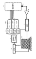
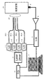
複数波長の光を同一の光出力口から被測定物の同一領域に照射する場合、光を合波するために光カプラを用いるが、その際原理的に光カプラ1つにつき3dBの光損失が生じる。光の波長の数に応じて必要な光カプラが増加し、光の損失が大きくなり無視できないものとなる。また、光カプラのコストが大きくなる。例えば、4波長の光を用いてOPBS法を行う場合の濃度測定装置の構成を図18に示す。 When irradiating multiple wavelengths of light from the same light output port to the same region of the object to be measured, an optical coupler is used to multiplex the light. In principle, an optical loss of 3 dB per optical coupler is used. Arise. The number of required optical couplers increases according to the number of wavelengths of light, and the loss of light becomes large and cannot be ignored. In addition, the cost of the optical coupler increases. For example, FIG. 18 shows a configuration of a concentration measuring apparatus when the OPBS method is performed using light of four wavelengths.
図18の成分濃度測定装置は、レーザ光を放射するレーザダイオード1−1〜1−4と、レーザダイオード1−1〜1−4を駆動するレーザドライバ2と、レーザダイオード1−1〜1−4から放射されたレーザ光を導く光ファイバ3−1〜3−4と、レーザダイオード1−1,1−2から放射されたレーザ光を合波する光カプラ4−1と、レーザダイオード1−3,1−4から放射されたレーザ光を合波する光カプラ4−2と、光カプラ4−1によって合波されたレーザ光を導く光ファイバ5−1と、光カプラ4−2によって合波されたレーザ光を導く光ファイバ5−2と、光ファイバ5−1,5−2からのレーザ光を合波する光カプラ6と、光カプラ6によって合波されたレーザ光を導く光ファイバ7と、光音響効果によって被測定物13から発生する光音響信号を検出し、音圧に比例した電気信号に変換する音響センサ8と、音響センサ8から出力された電気信号を増幅する増幅器9と、参照信号を発生するファンクションジェネレータ10と、増幅器9の出力信号とファンクションジェネレータ10から出力された参照信号とを入力として、増幅器9の出力信号から所望の周波数の測定信号を検出するロックインアンプ11と、ファンクションジェネレータ10およびロックインアンプ11を制御すると共に、ロックインアンプ11が検出した測定信号を処理して特定の成分濃度を導出するコンピュータからなる情報処理装置12とから構成される。
18 includes laser diodes 1-1 to 1-4 that emit laser light, a
複数の波長の光を合波する上記以外の装置構成としては、図19に示すようにアレイ導波路型回折格子(AWG:arrayed-waveguide grating)14と、AWG14によって合波されたレーザ光を導く光ファイバ15とを用いる構成や、図20に示すように偏光ビームスプリッタ(PBS:Polarizing Beam Splitter)16−1〜16−4を用いる構成や、図21に示すように回折格子17を用いる構成がある。しかしながら、図19〜図21に示した構成では、実効的な光の損失が避けられず、装置構成も複雑になってしまうことが問題である。
As an apparatus configuration other than the above that multiplexes light of a plurality of wavelengths, as shown in FIG. 19, an arrayed-waveguide grating (AWG) 14 and laser light combined by the AWG 14 are guided. A configuration using the
本発明は、上記課題を解決するためになされたもので、装置構成を簡略化し、また光損失を低減することができる成分濃度測定装置を提供することを目的とする。 The present invention has been made to solve the above-described problems, and an object of the present invention is to provide a component concentration measuring apparatus that can simplify the apparatus configuration and reduce optical loss.
本発明の成分濃度測定装置は、互いに波長が異なるn波(nは3以上の整数)の光のうち2波の光を同一の周波数で且つ異なる位相の信号によりそれぞれ強度変調して放射する光源と、この光源からの2波の光をそれぞれ独立に被測定物に導く光導波手段と、前記2波の光のうち少なくとも一方の光のパワーを変化させる光パワー制御手段と、光照射によって前記被測定物から発生する光音響信号を検出して電気信号を出力する光音響信号検出手段と、前記2波の光のうち少なくとも一方の光のパワーを測定する光強度測定手段と、前記電気信号の強度を測定する信号強度測定手段と、光のパワーを変化させて前記電気信号の強度が最低となったときの前記光強度測定手段の測定結果に基づいて、前記被測定物に含まれる測定対象の成分の濃度を導出する濃度導出手段とを備え、前記光導波手段は、前記光源からのn波の光を前記被測定物に独立に照射するためのn個の出射端が互いに近接して配置されたものであり、前記濃度導出手段は、前記n波の光の中から選択し得る2波の組み合わせのうち少なくとも一部の組み合わせの各々について求めた前記光強度測定手段の測定結果に基づいて、前記測定対象の成分の濃度を導出することを特徴とするものである。 The component concentration measuring apparatus of the present invention is a light source that emits light of two waves out of n waves (n is an integer of 3 or more) having different wavelengths by intensity-modulating them with signals having the same frequency and different phases. And optical waveguide means for independently guiding the two waves of light from the light source to the object to be measured; optical power control means for changing the power of at least one of the two waves of light; and A photoacoustic signal detecting means for detecting a photoacoustic signal generated from the object to be measured and outputting an electric signal; a light intensity measuring means for measuring the power of at least one of the two waves of light; and the electric signal. A signal intensity measuring means for measuring the intensity of the light, and a measurement included in the object to be measured based on a measurement result of the light intensity measuring means when the intensity of the electric signal is minimized by changing the power of light. Concentration of target component Concentration derivation means for deriving light from the light source, wherein the optical waveguide means is arranged such that n output ends for independently irradiating the object to be measured with n-wave light from the light source are arranged close to each other And the concentration deriving unit is configured to perform the measurement based on the measurement result of the light intensity measuring unit obtained for each of at least some of the combinations of two waves that can be selected from the n-wave light. It is characterized by deriving the concentration of the target component.
また、本発明の成分濃度測定装置の1構成例において、前記光導波手段のn個の出射端の間隔は、前記被測定物に照射される2波の光が互いに重なる領域の体積が所定値以上となるように設定されることを特徴とするものである。
また、本発明の成分濃度測定装置の1構成例において、前記光導波手段のn個の出射端と前記被測定物との間隔は、前記被測定物に照射される2波の光が互いに重なる領域の体積が所定値以上となるように設定されることを特徴とするものである。
また、本発明の成分濃度測定装置の1構成例は、さらに、前記光導波手段のn個の出射端と前記被測定物との間に前記n個の出射端を固定するように設けられた、光を透過する材料からなるスペーサを備えることを特徴とするものである。
Further, in one configuration example of the component concentration measuring apparatus of the present invention, the interval between the n emission ends of the optical waveguide means is such that the volume of a region where two waves of light irradiated on the object to be measured overlap each other is a predetermined value. It is set so that it may become the above.
Further, in one configuration example of the component concentration measuring apparatus of the present invention, the distance between the n emission ends of the optical waveguide means and the object to be measured is such that two waves of light irradiated on the object to be measured overlap each other. The volume of the region is set to be a predetermined value or more.
Further, one configuration example of the component concentration measuring apparatus of the present invention is further provided so as to fix the n output ends between the n output ends of the optical waveguide means and the object to be measured. And a spacer made of a material that transmits light.
また、本発明の成分濃度測定装置の1構成例において、前記光導波手段は、少なくとも前記被測定物に近い部分がファイバアレイで構成され、このファイバアレイのn本のファイバの出射端が前記被測定物と対向するように配置されることを特徴とするものである。
また、本発明の成分濃度測定装置の1構成例において、前記光導波手段は、少なくとも前記被測定物に近い部分がマルチコアファイバで構成され、このマルチコアファイバのn個のコアの出射端が前記被測定物と対向するように配置されることを特徴とするものである。
また、本発明の成分濃度測定装置の1構成例は、さらに、前記光導波手段のn個の出射端と前記被測定物との間に、前記光導波手段からの光を前記被測定物に集光するための光学系を備えることを特徴とするものである。
また、本発明の成分濃度測定装置の1構成例において、前記光学系は、前記光導波手段からの光を平行に出射するものである。
Further, in one configuration example of the component concentration measuring apparatus of the present invention, the optical waveguide means includes at least a portion close to the object to be measured by a fiber array, and an output end of n fibers of the fiber array has the object to be measured. It arrange | positions so that a measurement object may be opposed, It is characterized by the above-mentioned.
Further, in one configuration example of the component concentration measuring apparatus according to the present invention, the optical waveguide means is formed of a multi-core fiber at least at a portion close to the object to be measured, and the exit ends of n cores of the multi-core fiber are the objects to be measured. It arrange | positions so that a measurement object may be opposed, It is characterized by the above-mentioned.
Further, in one configuration example of the component concentration measuring apparatus of the present invention, the light from the optical waveguide means is further applied to the measurement object between the n emission ends of the optical waveguide means and the measurement object. An optical system for condensing light is provided.
Moreover, in one structural example of the component concentration measuring apparatus of this invention, the said optical system radiate | emits the light from the said optical waveguide means in parallel.
本発明によれば、光源からの光をそれぞれ独立に被測定物に導く光導波手段を設け、光源からのn波の光を被測定物に独立に照射するための光導波手段のn個の出射端を互いに近接して配置することにより、光カプラなどの合波器を必要とせず、成分濃度測定装置の光学系の構成を簡略化することができ、光損失を低減することができる。また、本発明では、光の損失を低減することで光源に要求される出力強度を緩和することができる。また、本発明では、測定に用いる光の波長数(光源数)が増えても、光導波手段の変更のみで装置構成の大きな変更を伴わずに、波長数の変更に対応することができる。 According to the present invention, the optical waveguide means for guiding the light from the light source independently to the object to be measured is provided, and n light waveguide means for independently irradiating the object to be measured with the n-wave light from the light source. By arranging the emission ends close to each other, a multiplexer such as an optical coupler is not required, the configuration of the optical system of the component concentration measuring apparatus can be simplified, and light loss can be reduced. In the present invention, the output intensity required for the light source can be reduced by reducing the loss of light. Further, in the present invention, even if the number of wavelengths of light used for measurement (number of light sources) increases, it is possible to cope with a change in the number of wavelengths without changing the apparatus configuration only by changing the optical waveguide means.
また、本発明では、光導波手段のn個の出射端の間隔を、被測定物に照射される2波の光が互いに重なる領域の体積が所定値以上となるように設定することにより、OPBS法の実施可能な条件を満たすことができる。 Further, in the present invention, the interval between the n emission ends of the optical waveguide means is set so that the volume of the region where the two waves of light irradiating the object to be measured overlap each other is a predetermined value or more. Satisfy the legal requirements.
また、本発明では、光導波手段のn個の出射端と被測定物との間隔を、被測定物に照射される2波の光が互いに重なる領域の体積が所定値以上となるように設定することにより、OPBS法の実施可能な条件を満たすことができる。 In the present invention, the interval between the n output ends of the optical waveguide means and the object to be measured is set so that the volume of the region where the two waves of light irradiated on the object to be measured overlap each other is a predetermined value or more. By doing so, the conditions under which the OPBS method can be implemented can be satisfied.
また、本発明では、光導波手段のn個の出射端と被測定物との間に、光を透過する材料からなるスペーサを設けることにより、光導波手段のn個の出射端と被測定物との間隔を一定に維持することができる。 Further, in the present invention, by providing a spacer made of a material that transmits light between the n exit ends of the optical waveguide means and the object to be measured, the n exit ends of the optical waveguide means and the object to be measured are provided. Can be kept constant.
また、本発明では、光導波手段の少なくとも被測定物に近い部分をファイバアレイで構成することにより、光導波手段のn個の出射端の間隔を一定に維持することができる。 In the present invention, at least the portion of the optical waveguide means that is close to the object to be measured is configured with a fiber array, so that the interval between the n emission ends of the optical waveguide means can be kept constant.
また、本発明では、光導波手段の少なくとも被測定物に近い部分をマルチコアファイバで構成することにより、光導波手段のn個の出射端の間隔を一定に維持することができる。 In the present invention, at least a portion of the optical waveguide means that is close to the object to be measured is formed of a multi-core fiber, so that the interval between the n emission ends of the optical waveguide means can be kept constant.
また、本発明では、光導波手段のn個の出射端と被測定物との間に、光導波手段からの光を被測定物に集光するための光学系を設けることにより、光導波手段からの光をより近接させて被測定物に照射することができる。 In the present invention, an optical system for condensing light from the optical waveguide means on the object to be measured is provided between the n emission ends of the optical waveguide means and the object to be measured. It is possible to irradiate the object to be measured with the light from the nearer.
[第1の実施の形態]
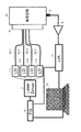
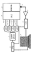
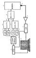
以下、本発明の実施の形態について図面を参照して説明する。図1は本発明の第1の実施の形態に係る成分濃度測定装置の構成を示すブロック図であり、図18〜図21と同様の構成には同一の符号を付してある。本実施の形態の成分濃度測定装置は、レーザ光を放射する光源となるレーザダイオード1−1〜1−4と、レーザダイオード1−1〜1−4を駆動するレーザドライバ2と、光音響効果によって被測定物13から発生する光音響信号を検出し、音圧に比例した電気信号に変換する光音響信号検出手段となる音響センサ8と、音響センサ8から出力された電気信号を増幅する増幅器9と、参照信号を発生するファンクションジェネレータ10と、増幅器9の出力信号とファンクションジェネレータ10から出力された参照信号とを入力として、増幅器9の出力信号から所望の周波数の測定信号を検出するロックインアンプ11と、ファンクションジェネレータ10およびロックインアンプ11を制御すると共に、ロックインアンプ11が検出した測定信号を処理して特定の成分濃度を導出するコンピュータからなる情報処理装置12と、レーザダイオード1−1〜1−4から放射されたレーザ光をそれぞれ独立に被測定物13に導く光導波手段となる光ファイバ20−1〜20−4とから構成される。
[First Embodiment]
Hereinafter, embodiments of the present invention will be described with reference to the drawings. FIG. 1 is a block diagram showing a configuration of a component concentration measuring apparatus according to the first embodiment of the present invention. The same reference numerals are given to the same configurations as those in FIGS. The component concentration measuring apparatus according to the present embodiment includes laser diodes 1-1 to 1-4 serving as light sources that emit laser light, a
情報処理装置12とファンクションジェネレータ10とは、光パワー制御手段を構成している。レーザダイオード1−1〜1−4の例としては、例えば分布帰還型半導体レーザ(DFB−LD)等がある。音響センサ8の例としては、マイクロホンがある。
The
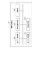
図2は情報処理装置12の構成を示すブロック図である。情報処理装置12は、ファンクションジェネレータ10を介して光のパワーを制御する光パワー制御部120と、レーザダイオード1−1〜1−4から放射された光のパワーを測定する光強度測定手段となる光パワー測定部121と、ロックインアンプ11から出力される測定信号の強度を測定する信号強度測定部122と、光パワー測定部121と信号強度測定部122の測定結果に基づいて、被測定物13内の特定成分(例えばグルコース)の濃度を導出する濃度導出部123と、情報記憶のための記憶部124とを有する。
FIG. 2 is a block diagram showing the configuration of the
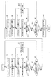
次に、本実施の形態の成分濃度測定装置の動作を図3のフローチャートを参照して説明する。レーザドライバ2から駆動電流が供給されると、レーザダイオード1−1〜1−4はレーザ光を放射する。本実施の形態では、4つのレーザダイオード1−1〜1−4のうちいずれか2つからレーザ光を放射させる。このとき、ファンクションジェネレータ10は、一方のレーザダイオードを駆動するための参照信号と、他方のレーザダイオードを駆動するための参照信号とを出力する。
Next, the operation of the component concentration measuring apparatus according to the present embodiment will be described with reference to the flowchart of FIG. When a drive current is supplied from the
レーザドライバ2は、ファンクションジェネレータ10から出力される2つの参照信号に応じて、同一周波数で逆位相の矩形波の駆動電流を2つのレーザダイオードに供給することにより、2つのレーザダイオードから放射される光を同一周波数で逆位相の信号によりそれぞれ強度変調する。
In response to the two reference signals output from the
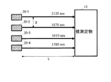
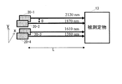
4つのレーザダイオード1−1〜1−4から放射される光の波長は互いに異なる。本実施の形態では、特許文献1で挙げている4波長を使うものとして、レーザダイオード1−1から放射される光の波長λ1を2120nm、レーザダイオード1−2から放射される光の波長λ2を1870nm、レーザダイオード1−3から放射される光の波長λ3を1610nm、レーザダイオード1−4から放射される光の波長λ4を1380nmとする。ファンクションジェネレータ10から出力される2つの参照信号の周波数は同一であり、位相がπ(180°)だけ異なっている。したがって、本実施の形態のように、4つのレーザダイオード1−1〜1−4のうちいずれか2つからレーザ光を放射させると、互いに異なる波長の2波のレーザ光を同一周波数で逆位相の信号によりそれぞれ強度変調して2つの強度変調光を生成することになる。
The wavelengths of light emitted from the four laser diodes 1-1 to 1-4 are different from each other. In the present embodiment, assuming that the four wavelengths listed in
まず、2つのレーザダイオード1−1,1−2(λ1=2120nm、λ2=1870nm)を動作させる。情報処理装置12の光パワー制御部120は、ファンクションジェネレータ10を制御して、レーザダイオード1−1を駆動するための参照信号の電圧V1、レーザダイオード1−2を駆動するための参照信号の電圧V2をそれぞれ初期値に設定することにより、レーザダイオード1−1から放射される光のパワーP1、レーザダイオード1−2から放射される光のパワーP2を初期値に設定する(図3ステップS1)。
First, two laser diodes 1-1 and 1-2 (λ 1 = 2120 nm, λ 2 = 1870 nm) are operated. The optical
レーザダイオード1−1,1−2から放射された強度変調光は、それぞれ光ファイバ20−1,20−2によって導かれ、被測定物13に照射される(図3ステップS2)。ここで、本実施の形態では、全ての光ファイバ20−1〜20−4の出射端が近接して配置されている。この近接配置については後でより詳細に説明する。 The intensity-modulated lights emitted from the laser diodes 1-1 and 1-2 are guided by the optical fibers 20-1 and 20-2, respectively, and irradiate the device under test 13 (step S2 in FIG. 3). Here, in the present embodiment, the emission ends of all the optical fibers 20-1 to 20-4 are arranged close to each other. This proximity arrangement will be described in more detail later.
情報処理装置12の光パワー測定部121は、レーザダイオード1−2から放射された光のパワーP2を測定する(図3ステップS3)。光パワー測定部121は、ファンクションジェネレータ10から出力されている、レーザダイオード1−2の駆動用の参照信号の電圧V2を取得する。情報処理装置12の記憶部124には、参照信号の電圧V2とレーザダイオード1−2から放射される光のパワーP2との関係を示すキャリブレーションデータが予め記憶されている。キャリブレーションデータは、電圧V2とパワーP2の実測により予め求めておくことができる。光パワー測定部121は、このようなキャリブレーションデータを参照し、取得した参照信号の電圧V2を、レーザダイオード1−2から放射された光のパワーP2に換算する。このパワーP2の値は記憶部124に格納される。
Light
音響センサ8は、被測定物13から発生する光音響信号を検出し、増幅器9は、音響センサ8から出力された電気信号を増幅する。ロックインアンプ11は、増幅器9の出力に含まれる信号のうち、ファンクションジェネレータ10から出力される参照信号によって決まる周波数の測定信号を検出する。
The
情報処理装置12の信号強度測定部122は、ロックインアンプ11から出力される測定信号の強度S(信号振幅)を測定する(図3ステップS4)。この強度Sの値は記憶部124に格納される。
The signal
予め定められた所定のパワーP2の範囲について測定を終えていない場合(図3ステップS5においてNO)、情報処理装置12の光パワー制御部120は、ファンクションジェネレータ10を制御して、レーザダイオード1−2を駆動するための参照信号の電圧V2を変化させることにより、レーザドライバ2からレーザダイオード1−2に供給される駆動電流の大きさを変化させ、レーザダイオード1−2から放射される光のパワーP2を変化させる(図3ステップS6)。このとき、レーザダイオード1−1を駆動するための参照信号の電圧V1は一定、すなわちレーザダイオード1−1から放射される光のパワーP1は初期値のまま一定である。こうして、予め定められた所定のパワーP2の範囲について測定を終えるまで(ステップS5においてYES)、ステップS3〜S6の処理が繰り返し実行される。
If the measurement has not been completed for a predetermined range of predetermined power P 2 (NO in step S5 in FIG. 3), the optical
予め定められたレーザの組み合わせについて測定を終えていない場合(図3ステップS7においてNO)、次のレーザの組み合わせ、具体的にはレーザダイオード1−1,1−3(λ1=2120nm、λ3=1610nm)を動作させる。光パワー制御部120は、ファンクションジェネレータ10を制御して、レーザダイオード1−1を駆動するための参照信号の電圧V1、レーザダイオード1−3を駆動するための参照信号の電圧V3をそれぞれ初期値に設定することにより、レーザダイオード1−1から放射される光のパワーP1、レーザダイオード1−3から放射される光のパワーP3を初期値に設定する(ステップS1)。
When the measurement is not completed for a predetermined laser combination (NO in step S7 in FIG. 3), the next laser combination, specifically, laser diodes 1-1 and 1-3 (λ 1 = 2120 nm, λ 3 = 1610 nm). Optical
レーザダイオード1−1,1−3から放射された強度変調光は、それぞれ光ファイバ20−1,20−3によって導かれ、被測定物13に照射される(ステップS2)。光パワー測定部121は、レーザダイオード1−3から放射された光のパワーP3を測定する(ステップS3)。光パワー測定部121は、参照信号の電圧V3とレーザダイオード1−3から放射される光のパワーP3との関係を示すキャリブレーションデータを用いて、参照信号の電圧V3を、光のパワーP3に換算する。このパワーP3の値は記憶部124に格納される。
The intensity-modulated lights emitted from the laser diodes 1-1 and 1-3 are guided by the optical fibers 20-1 and 20-3, respectively, and irradiated to the object to be measured 13 (step S2). The optical
ステップS4の処理は上記のとおりである。予め定められた所定のパワーP3の範囲について測定を終えていない場合(ステップS5においてNO)、光パワー制御部120は、ファンクションジェネレータ10を制御して、参照信号の電圧V3を変化させることにより、レーザダイオード1−3から放射される光のパワーP3を変化させる(ステップS6)。このとき、レーザダイオード1−1から放射される光のパワーP1は初期値のまま一定である。こうして、予め定められた所定のパワーP3の範囲について測定を終えるまで(ステップS5においてYES)、ステップS3〜S6の処理が繰り返し実行される。
The process of step S4 is as described above. If the measurement has not been completed for a predetermined range of predetermined power P 3 (NO in step S5), optical
次に、別のレーザの組み合わせ、具体的にはレーザダイオード1−1,1−4(λ1=2120nm、λ4=1380nm)を動作させる。光パワー制御部120は、ファンクションジェネレータ10を制御して、レーザダイオード1−1を駆動するための参照信号の電圧V1、レーザダイオード1−4を駆動するための参照信号の電圧V4をそれぞれ初期値に設定することにより、レーザダイオード1−1から放射される光のパワーP1、レーザダイオード1−4から放射される光のパワーP4を初期値に設定する(ステップS1)。
Next, another laser combination, specifically, laser diodes 1-1 and 1-4 (λ 1 = 2120 nm, λ 4 = 1380 nm) are operated. Optical
レーザダイオード1−1,1−4から放射された強度変調光は、それぞれ光ファイバ20−1,20−4によって導かれ、被測定物13に照射される(ステップS2)。光パワー測定部121は、レーザダイオード1−4から放射された光のパワーP4を測定する(ステップS3)。光パワー測定部121は、参照信号の電圧V4とレーザダイオード1−4から放射される光のパワーP4との関係を示すキャリブレーションデータを用いて、参照信号の電圧V4を、光のパワーP4に換算する。このパワーP4の値は記憶部124に格納される。
The intensity-modulated lights emitted from the laser diodes 1-1 and 1-4 are guided by the optical fibers 20-1 and 20-4, respectively, and irradiate the device under test 13 (step S2). The optical
ステップS4の処理は上記のとおりである。予め定められた所定のパワーP4の範囲について測定を終えていない場合(ステップS5においてNO)、光パワー制御部120は、ファンクションジェネレータ10を制御して、参照信号の電圧V4を変化させることにより、レーザダイオード1−4から放射される光のパワーP4を変化させる(ステップS6)。このとき、レーザダイオード1−1から放射される光のパワーP1は初期値のまま一定である。こうして、予め定められた所定のパワーP4の範囲について測定を終えるまで(ステップS5においてYES)、ステップS3〜S6の処理が繰り返し実行される。
The process of step S4 is as described above. If the measurement has not been completed for a predetermined range of predetermined power P 4 (NO in step S5), optical
次に、レーザダイオード1−2,1−3(λ2=1870nm、λ3=1610nm)を動作させる。このときの動作は、上記のレーザダイオード1−1,1−3(λ1=2120nm、λ3=1610nm)の組み合わせにおいて、レーザダイオード1−1の代わりにレーザダイオード1−2を用いたものに相当するので、説明は省略する。 Next, the laser diodes 1-2 and 1-3 (λ 2 = 1870 nm, λ 3 = 1610 nm) are operated. The operation at this time is based on the combination of the laser diodes 1-1 and 1-3 (λ 1 = 2120 nm, λ 3 = 1610 nm) using the laser diode 1-2 instead of the laser diode 1-1. Since it corresponds, description is abbreviate | omitted.
次に、レーザダイオード1−2,1−4(λ2=1870nm、λ4=1380nm)を動作させる。このときの動作は、上記のレーザダイオード1−1,1−4(λ1=2120nm、λ4=1380nm)の組み合わせにおいて、レーザダイオード1−1の代わりにレーザダイオード1−2を用いたものに相当するので、説明は省略する。 Next, the laser diodes 1-2 and 1-4 (λ 2 = 1870 nm, λ 4 = 1380 nm) are operated. The operation at this time is based on the combination of the laser diodes 1-1 and 1-4 (λ 1 = 2120 nm, λ 4 = 1380 nm) using the laser diode 1-2 instead of the laser diode 1-1. Since it corresponds, description is abbreviate | omitted.
最後に、レーザダイオード1−3,1−4(λ3=1610nm、λ4=1380nm)を動作させる。このときの動作は、上記のレーザダイオード1−1,1−4(λ1=2120nm、λ4=1380nm)の組み合わせにおいて、レーザダイオード1−1の代わりにレーザダイオード1−3を用いたものに相当するので、説明は省略する。
こうして、選択し得る2つのレーザダイオードの全ての組み合わせについて測定を終えるまで(ステップS7においてYES)、ステップS1〜S6の処理を繰り返す。
Finally, the laser diodes 1-3 and 1-4 (λ 3 = 1610 nm, λ 4 = 1380 nm) are operated. The operation at this time is based on the combination of the laser diodes 1-1 and 1-4 (λ 1 = 2120 nm, λ 4 = 1380 nm) using the laser diode 1-3 instead of the laser diode 1-1. Since it corresponds, description is abbreviate | omitted.
Thus, until the measurement is completed for all combinations of two laser diodes that can be selected (YES in step S7), the processes in steps S1 to S6 are repeated.
次に、測定開始時から任意の時間t経過後に再び測定を行う。図3のステップS8,S9,S10,S11,S12,S13,S14の処理は、それぞれS1,S2,S3,S4,S5,S6,S7の処理と同じなので、説明は省略する。 Next, measurement is performed again after an arbitrary time t has elapsed since the start of measurement. Since the processes of steps S8, S9, S10, S11, S12, S13, and S14 in FIG. 3 are the same as the processes of S1, S2, S3, S4, S5, S6, and S7, respectively, description thereof is omitted.
測定開始時点と任意の時間t経過後の時点の2回測定を行った後に(図3ステップS14においてYES)、情報処理装置12の濃度導出部123は、被測定物13内の特定成分の濃度Ca,Cb,Cc,・・・、および被測定物13の温度Tを導出する(図3ステップS15)。
After performing the measurement twice at the measurement start time and the time after the elapse of an arbitrary time t (YES in step S14 in FIG. 3), the
2波長によるOPBS法をn波長(nは3以上の整数で、本実施の形態ではn=4)によるOPBS法に拡張すると、(n(n−1)/2)の組み合わせを取り得る。結果として、n個の光波長から、(n(n−1)/2)の方程式を得ることができる。ここで、M個(Mは2以上の整数)の未知パラメータ、例えばCa,Cb,Cc,・・・,Tを有する被測定物13を考える。上記のとおり、Ca,Cb,Cc,・・・は被測定物13中の特定成分の濃度であり、Tは被測定物の温度である。濃度Caの例としては、血液グルコースの濃度がある。濃度Cbの例としてはアルブミンの濃度がある。(n(n−1)/2)の方程式を解くためには、上記の波長の数nは(n(n−1)/2)>=Mを満たす整数である必要がある。
When the OPBS method using two wavelengths is expanded to the OPBS method using n wavelengths (n is an integer of 3 or more, and n = 4 in this embodiment), a combination of (n (n−1) / 2) can be taken. As a result, an equation of (n (n-1) / 2) can be obtained from n light wavelengths. Here, a device under
レーザダイオード1−1,1−2(λ1=2120nm、λ2=1870nm)の組み合わせを用いたときに、測定開始時点のステップS3〜S6の処理において測定信号の強度Sが最低となったときの光のパワーP2をP2(t=0)、任意の時間t経過後のステップS10〜S13の処理において測定信号の強度Sが最低となったときの光のパワーP2をP2(t)とすると、測定結果である信号レスポンスOPBS(λ1,λ2)は以下のようになる。 When the combination of the laser diodes 1-1 and 1-2 (λ 1 = 2120 nm, λ 2 = 1870 nm) is used, and the intensity S of the measurement signal becomes the lowest in the processing of steps S3 to S6 at the start of measurement. power P 2 to P 2 of the light (t = 0), the power P 2 of the light when the intensity S of the measurement signal becomes minimum in the process of step S10~S13 after an arbitrary time t elapsed P 2 ( Assuming that t), the signal response OPBS (λ 1 , λ 2 ) as the measurement result is as follows.
レーザダイオード1−1,1−3(λ1=2120nm、λ3=1610nm)の組み合わせを用いたときに、測定開始時点のステップS3〜S6の処理において測定信号の強度Sが最低となったときの光のパワーP3をP3(t=0)、任意の時間t経過後のステップS10〜S13の処理において測定信号の強度Sが最低となったときの光のパワーP3をP3(t)とすると、測定結果である信号レスポンスOPBS(λ1,λ3)は以下のようになる。 When the combination of the laser diodes 1-1 and 1-3 (λ 1 = 2120 nm, λ 3 = 1610 nm) is used, and the intensity S of the measurement signal becomes the lowest in the processing of steps S3 to S6 at the start of measurement. of P 3 (t = 0) the power P 3 of the light, the power P 3 of the light P 3 when the intensity S of the measurement signal becomes minimum in the process of step S10~S13 after an arbitrary time t has elapsed ( If t), the signal response OPBS (λ 1 , λ 3 ), which is the measurement result, is as follows.
レーザダイオード1−1,1−4(λ1=2120nm、λ4=1380nm)の組み合わせを用いたときに、測定開始時点のステップS3〜S6の処理において測定信号の強度Sが最低となったときの光のパワーP4をP4(t=0)、任意の時間t経過後のステップS10〜S13の処理において測定信号の強度Sが最低となったときの光のパワーP4をP4(t)とすると、測定結果である信号レスポンスOPBS(λ1,λ4)は以下のようになる。 When the combination of the laser diodes 1-1 and 1-4 (λ 1 = 2120 nm, λ 4 = 1380 nm) is used, and the intensity S of the measurement signal becomes the lowest in the processing of steps S3 to S6 at the start of measurement. power P 4 to P 4 of the light (t = 0), the power P 4 of the light P 4 when the intensity S of the measurement signal becomes minimum in the process of step S10~S13 after an arbitrary time t has elapsed ( If t), the signal response OPBS (λ 1 , λ 4 ) as a measurement result is as follows.
レーザダイオード1−2,1−3(λ2=1870nm、λ3=1610nm)の組み合わせを用いたときに、測定開始時点のステップS3〜S6の処理において測定信号の強度Sが最低となったときの光のパワーP3をP3(t=0)、任意の時間t経過後のステップS10〜S13の処理において測定信号の強度Sが最低となったときの光のパワーP3をP3(t)とすると、測定結果である信号レスポンスOPBS(λ2,λ3)は以下のようになる。 When the combination of the laser diodes 1-2 and 1-3 (λ 2 = 1870 nm, λ 3 = 1610 nm) is used, and the intensity S of the measurement signal becomes the lowest in the processing of steps S3 to S6 at the start of measurement. of P 3 (t = 0) the power P 3 of the light, the power P 3 of the light P 3 when the intensity S of the measurement signal becomes minimum in the process of step S10~S13 after an arbitrary time t has elapsed ( If t), the signal response OPBS (λ 2 , λ 3 ) as a measurement result is as follows.
レーザダイオード1−2,1−4(λ2=1870nm、λ4=1380nm)の組み合わせを用いたときに、測定開始時点のステップS3〜S6の処理において測定信号の強度Sが最低となったときの光のパワーP4をP4(t=0)、任意の時間t経過後のステップS10〜S13の処理において測定信号の強度Sが最低となったときの光のパワーP4をP4(t)とすると、測定結果である信号レスポンスOPBS(λ2,λ4)は以下のようになる。 When the combination of the laser diodes 1-2 and 1-4 (λ 2 = 1870 nm, λ 4 = 1380 nm) is used, and the intensity S of the measurement signal becomes the lowest in the processing of steps S3 to S6 at the start of measurement. power P 4 to P 4 of the light (t = 0), the power P 4 of the light P 4 when the intensity S of the measurement signal becomes minimum in the process of step S10~S13 after an arbitrary time t has elapsed ( If t), the signal response OPBS (λ 2 , λ 4 ), which is the measurement result, is as follows.
レーザダイオード1−3,1−4(λ3=1610nm、λ4=1380nm)の組み合わせを用いたときに、測定開始時点のステップS3〜S6の処理において測定信号の強度Sが最低となったときの光のパワーP4をP4(t=0)、任意の時間t経過後のステップS10〜S13の処理において測定信号の強度Sが最低となったときの光のパワーP4をP4(t)とすると、測定結果である信号レスポンスOPBS(λ3,λ4)は以下のようになる。 When the combination of laser diodes 1-3 and 1-4 (λ 3 = 1610 nm, λ 4 = 1380 nm) is used, and the intensity S of the measurement signal is the lowest in the processing of steps S3 to S6 at the start of measurement. power P 4 to P 4 of the light (t = 0), the power P 4 of the light P 4 when the intensity S of the measurement signal becomes minimum in the process of step S10~S13 after an arbitrary time t has elapsed ( If t), the signal response OPBS (λ 3 , λ 4 ), which is the measurement result, is as follows.
OPBS法による測定結果である信号レスポンスOPBS(λ1,λ2),OPBS(λ1,λ3),OPBS(λ1,λ4),・・・,OPBS(λn-1,λn)は、次式のように表現できる。n個(本実施の形態ではn=4)のレーザダイオードの中から選択し得る2つのレーザダイオードの全ての組み合わせはn(n−1)/2とおりであるから、OPBS法により得られる信号レスポンスもn(n−1)/2個となる。
OPBS(λ1,λ2)=Qaλ1,λ2Ca+Qbλ1,λ2Cb+Qcλ1,λ2Cc
+・・・+Qtλ1,λ2T
OPBS(λ1,λ3)=Qaλ1,λ3Ca+Qbλ1,λ3Cb+Qcλ1,λ3Cc
+・・・+Qtλ1,λ3T
OPBS(λ1,λ4)=Qaλ1,λ4Ca+Qbλ1,λ4Cb+Qcλ1,λ4Cc
+・・・+Qtλ1,λ4T
・・・
OPBS(λn-1,λn)=Qaλn-1,λnCa+Qbλn-1,λnCb+Qcλn-1,λnCc
+・・・+Qtλn-1,λnT ・・・(7)
Signal response OPBS (λ 1 , λ 2 ), OPBS (λ 1 , λ 3 ), OPBS (λ 1 , λ 4 ),..., OPBS (λ n−1 , λ n ) Can be expressed as: Since all combinations of two laser diodes that can be selected from n (in this embodiment, n = 4) laser diodes are n (n−1) / 2, the signal response obtained by the OPBS method Is also n (n-1) / 2.
OPBS (λ 1 , λ 2 ) = Qa λ1, λ2 Ca + Qb λ1, λ2 Cb + Qc λ1, λ2 Cc
+ ... + Qt λ1, λ2 T
OPBS (λ 1 , λ 3 ) = Qa λ1, λ3 Ca + Qb λ1, λ3 Cb + Qc λ1, λ3 Cc
+ ... + Qt λ1, λ3 T
OPBS (λ 1 , λ 4 ) = Qa λ1, λ4 Ca + Qb λ1, λ4 Cb + Qc λ1, λ4 Cc
+ ... + Qt λ1, λ4 T
...
OPBS (λ n−1 , λ n ) = Qa λn−1, λn Ca + Qb λn−1, λn Cb + Qc λn−1, λn Cc
+ ... + Qt λn-1, λn T (7)
ここで、Qaλi,λj,Qbλi,λj,Qcλi,λj,・・・,Qtλi,λj(i,j=1〜nで、i≠j)は比例係数である。この係数Qaλi,λj,Qbλi,λj,Qcλi,λj,・・・,Qtλi,λjの値は、想定されるそれぞれの組成物(グルコースやアルブミン、その他の血液成分等)を一つ一つ評価したキャリブレーション測定で予め実験的に得られている。こうして、濃度導出部123は、式(7)の連立方程式を解くことにより、M個の未知パラメータCa,Cb,Cc,・・・,Tを決定することができる。
Here, Qa λi, λj , Qb λi, λj , Qc λi, λj ,..., Qt λi, λj (i, j = 1 to n, i ≠ j) are proportional coefficients. One this factor Qa λi, λj, Qb λi, λj, Qc λi, λj, ···, Qt λi, the value of lambda] j are each composition envisioned (glucose and albumin, other blood components etc.) It is experimentally obtained in advance by one calibration measurement. Thus, the
なお、光の波長は本実施の形態の例に限るものではなく、また波長の組み合わせの順番も本実施の形態の順番どおりにしなくても構わない。光の波長は、目的とする成分の濃度を高精度に測定できるように適宜選択すればよい。また、n波の光の中から選択し得る2波の組み合わせの全てを使用しなくてもよく、選択し得る2波の組み合わせのうち一部を用いて測定を行ってもよい。 Note that the wavelength of light is not limited to the example of the present embodiment, and the order of combination of wavelengths may not be the same as the order of the present embodiment. The wavelength of the light may be appropriately selected so that the concentration of the target component can be measured with high accuracy. In addition, it is not necessary to use all combinations of two waves that can be selected from n-wave light, and measurement may be performed using some of the combinations of two waves that can be selected.
また、本実施の形態では、図4に示すように光ファイバ20−1〜20−4の出射端を1次元的に配置しているが、図5に示すように光ファイバ20−1〜20−4の出射端を2次元的に配置してもよい。 In the present embodiment, the output ends of the optical fibers 20-1 to 20-4 are arranged one-dimensionally as shown in FIG. 4, but the optical fibers 20-1 to 20-20 are shown in FIG. -4 may be arranged two-dimensionally.
本実施の形態では、隣接する光ファイバ20−1〜20−4の出射端の間隔(図4、図5のD)と、光ファイバ20−1〜20−4の出射端と被測定物13との間隔(図4、図5のL)を調節することで、光が照射される被測定物13上の領域を適切に設定することができる。
In this Embodiment, the space | interval (D of FIG. 4, FIG. 5) of the output end of adjacent optical fiber 20-1 to 20-4, the output end of optical fiber 20-1 to 20-4, and the to-
隣接する光ファイバ20−1〜20−4の出射端の間隔と、光ファイバ20−1〜20−4の出射端と被測定物13との間隔の目安について説明する。波長λの光がコア径dの光ファイバから照射された場合、光が距離z進んだときの光ビームの半径rは、光の回折から下記のように記述できる。
r=1.22(d/λ)z ・・・(8)
The standard of the space | interval of the output end of adjacent optical fiber 20-1 to 20-4 and the space | interval of the output end of optical fiber 20-1 to 20-4 and the to-
r = 1.22 (d / λ) z (8)
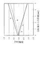
例えば1382nmと1610nmの波長の光を用いて、この2つの波長の光を出射する2本のシングルモードファイバ(ビーム径10μm)の出射端を100μmの間隔で近接させたときに、それぞれのシングルモードファイバから出射する光ビームの重なり方は図6に示すようになっている。
For example, when light of wavelengths of 1382 nm and 1610 nm is used and the exit ends of two single mode fibers (
図6の横軸は出射端からの距離、縦軸は2本のシングルモードファイバの出射端が並ぶ方向(例えば図4の上下方向)の距離である。ここでは、波長1382nmの光を出射するシングルモードファイバの出射端を縦軸上の距離0mmの位置に配置し、波長1610nmの光を出射するシングルモードファイバの出射端を100μmずらしていることになる。 The horizontal axis in FIG. 6 is the distance from the emission end, and the vertical axis is the distance in the direction in which the emission ends of the two single mode fibers are aligned (for example, the vertical direction in FIG. 4). Here, the exit end of the single mode fiber that emits light having a wavelength of 1382 nm is arranged at a distance of 0 mm on the vertical axis, and the exit end of the single mode fiber that emits light having a wavelength of 1610 nm is shifted by 100 μm. .
2本の直線60,61は波長1382nmの光ビームの外縁を表しており、この直線60,61で囲まれる領域が波長1382nmの光ビームが照射される領域である。同様に、2本の直線62,63は波長1610nmの光ビームの外縁を表しており、この直線62,63で囲まれる領域が波長1610nmの光ビームが照射される領域である。光ビームが重なる領域のズレが200μm程度以下に収まることが望ましいため、図6の例の場合、シングルモードファイバの出射端と被測定物13との間隔を2mm以上として測定を行うことが望ましいことが分かる。
The two
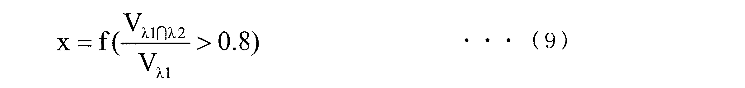
OPBS法が実施可能な条件として、2つの波長の光のうち1つの波長の光が照射される領域の体積を100%としたとき、照射される2つの波長の光が互いに重なる領域の体積が80%以上になることが望ましい。他の波長の組み合わせの場合も本条件を満たすように光を照射することが望ましい。また、この条件を満たすように光ファイバ20−1〜20−4の出射端を配置することが必要である。光ファイバの出射端と被測定物13との間隔xは、1つの波長の光が照射される領域の体積Vλ1と、2つの波長の光が互いに重なる領域の体積Vλ1∩λ2の条件を満たす関数として下記のように書くことができる。 As a condition under which the OPBS method can be performed, when the volume of a region irradiated with one wavelength of light of two wavelengths is 100%, the volume of the region where the irradiated two wavelengths of light overlap each other is It is desirable to be 80% or more. In the case of other wavelength combinations, it is desirable to irradiate light so as to satisfy this condition. Further, it is necessary to arrange the emission ends of the optical fibers 20-1 to 20-4 so as to satisfy this condition. The distance x between the exit end of the optical fiber and the object to be measured 13 satisfies the condition of the volume V λ1 of the region irradiated with light of one wavelength and the volume V λ1∩λ2 of the region where light of two wavelengths overlap each other. It can be written as a function that satisfies:
測定に際し、OPBS信号を観察し、光音響効果により発生する測定信号の強度Sの最小値を見ることで、光が照射される被測定物13上の領域の調節が適切かどうかを確認することができる。
At the time of measurement, by observing the OPBS signal and checking the minimum value of the intensity S of the measurement signal generated by the photoacoustic effect, it is confirmed whether the adjustment of the area on the
具体的には、従来のように測定に利用する2波長の光を光カプラで合波して被測定物13に照射したときに光音響効果により発生する測定信号の強度Sの最小値と、本実施の形態の構成で2波長の光を被測定物13に照射したときに光音響効果により発生する測定信号の強度Sの最小値とを比較することで、本実施の形態の構成で被測定物13に光が適切に照射されているかどうかを確認することができる。
Specifically, the minimum value of the intensity S of the measurement signal generated by the photoacoustic effect when the two-wavelength light used for the measurement is combined by the optical coupler and irradiated to the object to be measured 13 as in the past, By comparing with the minimum value of the intensity S of the measurement signal generated by the photoacoustic effect when the light to be measured 13 is irradiated with light of two wavelengths in the configuration of the present embodiment, the configuration of the present embodiment It can be confirmed whether the
光ファイバ20−1〜20−4の出射端と被測定物13との間隔の維持が不完全であると、測定精度が劣化するため、図7に示すように間隔を調節するために光の吸収の少ない光透過材料からなるスペーサ21を光ファイバ20−1〜20−4の出射端と被測定物13との間に設けることが望ましい。このようなスペーサ21に光ファイバ20−1〜20−4の出射端を固定すればよい。スペーサ21の材料としては、例えば、石英、サファイアグラスが利用できる。スペーサ21には、反射防止膜が設けられていることが望ましい。
If the distance between the exit ends of the optical fibers 20-1 to 20-4 and the device under
同様に、光ファイバ20−1〜20−4の出射端には、反射防止膜が設けられていることが望ましい。反射防止膜を設けることで、光が照射される領域が多重反射によって不安定になることを防止することができる。 Similarly, it is desirable that an antireflection film is provided at the exit end of the optical fibers 20-1 to 20-4. By providing the antireflection film, it is possible to prevent the region irradiated with light from becoming unstable due to multiple reflection.
以上のように、本実施の形態では、光カプラなどの合波器を必要とせず、成分濃度測定装置の光学系の構成を簡略化することができ、光損失を低減することができる。4波長の光を用いる場合で考えると、図18に示した従来の成分濃度測定装置の構成と比較して光カプラ3つを省略することができるので、光損失については6dB分低減することができる。 As described above, in this embodiment, a multiplexer such as an optical coupler is not required, the configuration of the optical system of the component concentration measuring apparatus can be simplified, and light loss can be reduced. Considering the case of using light of four wavelengths, three optical couplers can be omitted as compared with the configuration of the conventional component concentration measuring apparatus shown in FIG. 18, so that the optical loss can be reduced by 6 dB. it can.
特許文献1によれば、血液中グルコースの濃度測定に利用する光として、2120nm、1870nm、1610nm、1380nmの4波長を提案している。この場合、測定の組み合わせとして6セットの測定を行う必要があるが、本実施の形態のように、光ファイバ20−1〜20−4の出射端を十分に近接させておけば、光カプラを用いることなく、光のオン/オフだけで測定を行うことができる。
According to
[第2の実施の形態]
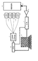
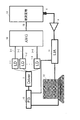
次に、本発明の第2の実施の形態について説明する。図8は本発明の第2の実施の形態に係る成分濃度測定装置の構成を示すブロック図であり、図1と同一の構成には同一の符号を付してある。本実施の形態の成分濃度測定装置は、レーザダイオード1−1〜1−4と、レーザドライバ2と、音響センサ8と、増幅器9と、ファンクションジェネレータ10と、ロックインアンプ11と、情報処理装置12と、光ファイバ20−1〜20−4と、光ファイバ20−1〜20−4と共に光導波手段を構成するファイバアレイ22とから構成される。
[Second Embodiment]
Next, a second embodiment of the present invention will be described. FIG. 8 is a block diagram showing a configuration of a component concentration measuring apparatus according to the second embodiment of the present invention. The same components as those in FIG. 1 are denoted by the same reference numerals. The component concentration measuring apparatus according to the present embodiment includes laser diodes 1-1 to 1-4, a
本実施の形態は、第1の実施の形態において、光ファイバ20−1〜20−4の先端にファイバアレイ22を接続し、このファイバアレイ22から被測定物13に光を照射するようにしたものである。第1の実施の形態の例では、4本の光ファイバ20−1〜20−4を用いているので、ファイバアレイ22としては、4本の光ファイバ20−1〜20−4からの光を被測定物13に独立に導く光ファイバ芯線が最低4芯あるものを用いればよい。
In the present embodiment, in the first embodiment, the
ファイバアレイ22中の各ファイバの出射端の間隔と、ファイバアレイ22中の各ファイバの出射端と被測定物13との間隔は、第1の実施の形態の式(9)で説明した条件を満たすように設定すればよい。被測定物13内の特定成分の濃度の測定方法は第1の実施の形態で説明したとおりである。こうして、本実施の形態では、第1の実施の形態と同様の効果を得ることができる。
The distance between the emission ends of the fibers in the
[第3の実施の形態]
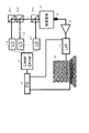
次に、本発明の第3の実施の形態について説明する。図9は本発明の第3の実施の形態に係る成分濃度測定装置の構成を示すブロック図であり、図1と同一の構成には同一の符号を付してある。本実施の形態の成分濃度測定装置は、レーザダイオード1−1〜1−4と、レーザドライバ2と、音響センサ8と、増幅器9と、ファンクションジェネレータ10と、ロックインアンプ11と、情報処理装置12と、光ファイバ20−1〜20−4と、光ファイバ20−1〜20−4と共に光導波手段を構成する平面光波回路(PLC:Planar Lightwave Circuit)23とから構成される。
[Third Embodiment]
Next, a third embodiment of the present invention will be described. FIG. 9 is a block diagram showing a configuration of a component concentration measuring apparatus according to the third embodiment of the present invention. The same components as those in FIG. 1 are denoted by the same reference numerals. The component concentration measuring apparatus according to the present embodiment includes laser diodes 1-1 to 1-4, a
本実施の形態は、第1の実施の形態において、光ファイバ20−1〜20−4の先端にPLC23を接続し、このPLC23から被測定物13に光を照射するようにしたものである。第1の実施の形態の例では、4本の光ファイバ20−1〜20−4を用いているので、PLC23としては、4本の光ファイバ20−1〜20−4からの光を被測定物13に独立に導く光導波路が最低4つあるものを用いればよい。
In the present embodiment, a PLC 23 is connected to the tips of the optical fibers 20-1 to 20-4 in the first embodiment, and the device under
PLC23中の各光導波路の出射端の間隔と、PLC23中の各光導波路の出射端と被測定物13との間隔は、第1の実施の形態の式(9)で説明した条件を満たすように設定すればよい。被測定物13内の特定成分の濃度の測定方法は第1の実施の形態で説明したとおりである。こうして、本実施の形態では、第1の実施の形態と同様の効果を得ることができる。
The interval between the exit ends of the optical waveguides in the PLC 23 and the interval between the exit end of each optical waveguide in the PLC 23 and the object to be measured 13 satisfy the conditions described in the expression (9) of the first embodiment. Should be set. The method for measuring the concentration of the specific component in the
[第4の実施の形態]
次に、本発明の第4の実施の形態について説明する。図10は本発明の第4の実施の形態に係る成分濃度測定装置の構成を示すブロック図であり、図1と同一の構成には同一の符号を付してある。本実施の形態の成分濃度測定装置は、レーザダイオード1−1〜1−4と、レーザドライバ2と、音響センサ8と、増幅器9と、ファンクションジェネレータ10と、ロックインアンプ11と、情報処理装置12と、光ファイバ20−1〜20−4と、光ファイバ20−1〜20−4と共に光導波手段を構成するマルチコアファイバ24とから構成される。
[Fourth Embodiment]
Next, a fourth embodiment of the present invention will be described. FIG. 10 is a block diagram showing the configuration of a component concentration measuring apparatus according to the fourth embodiment of the present invention. The same components as those in FIG. 1 are denoted by the same reference numerals. The component concentration measuring apparatus according to the present embodiment includes laser diodes 1-1 to 1-4, a
本実施の形態は、第1の実施の形態において、光ファイバ20−1〜20−4の先端にマルチコアファイバ24を接続し、このマルチコアファイバ24から被測定物13に光を照射するようにしたものである。第2の実施の形態で説明したファイバアレイ22が複数の光ファイバ芯線を束ねたものであるのに対して、マルチコアファイバ24は、クラッド内に複数のコアを設けたものである。第1の実施の形態の例では、4本の光ファイバ20−1〜20−4を用いているので、マルチコアファイバ24としては、4本の光ファイバ20−1〜20−4からの光を被測定物13に独立に導くコアが最低4つあるものを用いればよい。
In the present embodiment, in the first embodiment, the
マルチコアファイバ24中の各コアの出射端の間隔と、マルチコアファイバ24中の各コアの出射端と被測定物13との間隔は、第1の実施の形態の式(9)で説明した条件を満たすように設定すればよい。被測定物13内の特定成分の濃度の測定方法は第1の実施の形態で説明したとおりである。こうして、本実施の形態では、第1の実施の形態と同様の効果を得ることができる。
The distance between the emission ends of the cores in the
[第5の実施の形態]
次に、本発明の第5の実施の形態について説明する。図11は本発明の第5の実施の形態に係る成分濃度測定装置の構成を示すブロック図であり、図1と同一の構成には同一の符号を付してある。本実施の形態の成分濃度測定装置は、レーザダイオード1−1〜1−4と、レーザドライバ2と、音響センサ8と、増幅器9と、ファンクションジェネレータ10と、ロックインアンプ11と、情報処理装置12と、光ファイバ20−1〜20−4とから構成される。
[Fifth Embodiment]
Next, a fifth embodiment of the present invention will be described. FIG. 11 is a block diagram showing the configuration of a component concentration measuring apparatus according to the fifth embodiment of the present invention. The same components as those in FIG. 1 are denoted by the same reference numerals. The component concentration measuring apparatus according to the present embodiment includes laser diodes 1-1 to 1-4, a
本実施の形態は、第1の実施の形態において、光ファイバのような光導波手段を用いるのではなく、光源となるレーザダイオード1−1〜1−4を被測定物13に近接配置して、レーザダイオード1−1〜1−4から被測定物13に光を直接照射するようにしたものである。
In this embodiment, instead of using an optical waveguide means such as an optical fiber in the first embodiment, laser diodes 1-1 to 1-4 serving as light sources are arranged close to the
各レーザダイオード1−1〜1−4の出射端の間隔と、各レーザダイオード1−1〜1−4の出射端と被測定物13との間隔は、第1の実施の形態の式(9)で説明した条件を満たすように設定すればよい。被測定物13内の特定成分の濃度の測定方法は第1の実施の形態で説明したとおりである。こうして、本実施の形態では、第1の実施の形態と同様の効果を得ることができる。また、本実施の形態では、光ファイバのような光導波手段を省くことができる。
The intervals between the emission ends of the laser diodes 1-1 to 1-4 and the intervals between the emission ends of the laser diodes 1-1 to 1-4 and the object to be measured 13 are expressed by the equation (9) in the first embodiment. It suffices to set so as to satisfy the conditions described in). The method for measuring the concentration of the specific component in the
[第6の実施の形態]
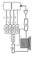
次に、本発明の第6の実施の形態について説明する。図12は本発明の第6の実施の形態に係る成分濃度測定装置の構成を示すブロック図であり、図1と同一の構成には同一の符号を付してある。本実施の形態の成分濃度測定装置は、レーザドライバ2aと、音響センサ8と、増幅器9と、ファンクションジェネレータ10と、ロックインアンプ11と、情報処理装置12と、光ファイバ20−1〜20−4と、垂直共振器型面発光レーザ(VCSEL:Vertical Cavity Surface Emitting Laser)25−1〜25−4とから構成される。
[Sixth Embodiment]
Next, a sixth embodiment of the present invention will be described. FIG. 12 is a block diagram showing the configuration of a component concentration measuring apparatus according to the sixth embodiment of the present invention. The same components as those in FIG. 1 are denoted by the same reference numerals. The component concentration measuring apparatus according to the present embodiment includes a
本実施の形態は、第1の実施の形態において、レーザダイオード1−1〜1−4の代わりに、光源としてVCSEL25−1〜25−4を用いたものである。レーザドライバ2aは、VCSEL25−1〜25−4を駆動する。4つのVCSEL25−1〜25−4から放射される光の波長は互いに異なる。光ファイバ20−1〜20−4は、VCSEL25−1〜25−4から放射されたレーザ光を被測定物13に導く。
In the present embodiment, VCSELs 25-1 to 25-4 are used as light sources instead of the laser diodes 1-1 to 1-4 in the first embodiment. The
その他の構成は第1の実施の形態と同様であり、本実施の形態においても、第1の実施の形態と同様の効果を得ることができる。なお、本実施の形態のVCSEL25−1〜25−4を第2〜第5の実施の形態に適用してもよいことは言うまでもない。 Other configurations are the same as those of the first embodiment, and the same effects as those of the first embodiment can also be obtained in this embodiment. Needless to say, the VCSELs 25-1 to 25-4 of this embodiment may be applied to the second to fifth embodiments.
[第7の実施の形態]
次に、本発明の第7の実施の形態について説明する。図13は本発明の第7の実施の形態に係る成分濃度測定装置の構成を示すブロック図であり、図1と同一の構成には同一の符号を付してある。本実施の形態の成分濃度測定装置は、ドライバ2bと、音響センサ8と、増幅器9と、ファンクションジェネレータ10と、ロックインアンプ11と、情報処理装置12と、光ファイバ20−1〜20−4と、発光ダイオード(LED:Light Emitting Diode)26−1〜26−4とから構成される。
[Seventh Embodiment]
Next, a seventh embodiment of the present invention will be described. FIG. 13 is a block diagram showing the configuration of a component concentration measuring apparatus according to the seventh embodiment of the present invention. The same components as those in FIG. 1 are denoted by the same reference numerals. The component concentration measuring apparatus according to the present embodiment includes a
本実施の形態は、第1の実施の形態において、レーザダイオード1−1〜1−4の代わりに、光源としてLED26−1〜26−4を用いたものである。ドライバ2bは、LED26−1〜26−4を駆動する。4つのLED26−1〜26−4から放射される光の波長は互いに異なる。光ファイバ20−1〜20−4は、LED26−1〜26−4から放射されたレーザ光を被測定物13に導く。
In the present embodiment, LEDs 26-1 to 26-4 are used as light sources instead of the laser diodes 1-1 to 1-4 in the first embodiment. The
その他の構成は第1の実施の形態と同様であり、本実施の形態においても、第1の実施の形態と同様の効果を得ることができる。なお、本実施の形態のLED26−1〜26−4を第2〜第5の実施の形態に適用してもよいことは言うまでもない。 Other configurations are the same as those of the first embodiment, and the same effects as those of the first embodiment can also be obtained in this embodiment. Needless to say, the LEDs 26-1 to 26-4 of the present embodiment may be applied to the second to fifth embodiments.
[第8の実施の形態]
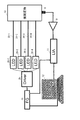
次に、本発明の第8の実施の形態について説明する。図14は本発明の第8の実施の形態に係る成分濃度測定装置の構成を示すブロック図であり、図1と同一の構成には同一の符号を付してある。本実施の形態の成分濃度測定装置は、レーザダイオード1−1〜1−4と、レーザドライバ2と、音響センサ8と、増幅器9と、ファンクションジェネレータ10と、ロックインアンプ11と、情報処理装置12と、光ファイバ20−1〜20−4と、光ファイバ20−1〜20−4から照射された光を被測定物13に集光するための光学系27とから構成される。
[Eighth Embodiment]
Next, an eighth embodiment of the present invention will be described. FIG. 14 is a block diagram showing the configuration of a component concentration measuring apparatus according to the eighth embodiment of the present invention. The same components as those in FIG. The component concentration measuring apparatus according to the present embodiment includes laser diodes 1-1 to 1-4, a
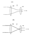
本実施の形態は、第1の実施の形態において、光ファイバ20−1〜20−4の出射端と被測定物13との間に光学系27を設けたものである。光学系27としては、1枚乃至は複数枚のレンズがある。被測定物13内の特定成分の濃度の測定方法は第1の実施の形態で説明したとおりである。こうして、本実施の形態では、第1の実施の形態と同様の効果を得ることができる。また、本実施の形態では、光学系27としてレンズを用いることで、各光ファイバ20−1〜20−4からの光をより近接させて被測定物13に照射することができる。
In the present embodiment, an
光学系27の具体的な構成としては、図15(A)に示すように、2枚のレンズ100,101または2枚以上のレンズを用いて光ファイバ20−1〜20−4からの平行な光をビーム幅を狭めて平行に出射するガリレー型の構成や、図15(B)に示すように、2枚のレンズ102,103または2枚以上のレンズを用いて光ファイバ20−1〜20−4からの平行な光をビーム幅を狭めて平行に出射するケプラー型の構成がある。
As a specific configuration of the
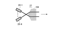
あるいは、光学系27として、図16に示すように、適当な角度を持って配置された光ファイバ20−1〜20−4から照射される光に対して平行なビームを出射するプリズム104を用いてもよい。
Alternatively, as the
[第9の実施の形態]
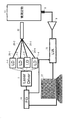
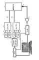
次に、本発明の第9の実施の形態について説明する。図17は本発明の第9の実施の形態に係る成分濃度測定装置の構成を示すブロック図であり、図1、図18と同一の構成には同一の符号を付してある。本実施の形態の成分濃度測定装置は、レーザダイオード1−1〜1−4と、レーザドライバ2と、光ファイバ3−1〜3−4と、光カプラ4−1,4−2と、音響センサ8と、増幅器9と、ファンクションジェネレータ10と、ロックインアンプ11と、情報処理装置12と、光ファイバ28−1,28−2とから構成される。
[Ninth Embodiment]
Next, a ninth embodiment of the present invention will be described. FIG. 17 is a block diagram showing the configuration of the component concentration measuring apparatus according to the ninth embodiment of the present invention. The same components as those in FIGS. 1 and 18 are given the same reference numerals. The component concentration measuring apparatus according to the present embodiment includes laser diodes 1-1 to 1-4, a
本実施の形態は、図18に示した従来の構成において、光カプラ6を省いたものである。光ファイバ28−1,28−2は、それぞれ光カプラ4−1,4−2からの光を被測定物13に導く。被測定物13内の特定成分の濃度の測定方法は第1の実施の形態で説明したとおりである。
In the present embodiment, the
本実施の形態では、第1の実施の形態と比較して光カプラ4−1,4−2の分だけ光損失が増大するが、図18に示した従来の構成と比較して光カプラ1つを省略することができ、光損失については3dB分低減することができる。
In this embodiment, the optical loss is increased by the amount of the optical couplers 4-1 and 4-2 as compared with the first embodiment, but the
第1〜第9の実施の形態の情報処理装置12は、例えばCPU(Central Processing Unit)、記憶装置およびインタフェースを備えたコンピュータとこれらのハードウェア資源を制御するプログラムによって実現することができる。CPUは、記憶装置に格納されたプログラムに従って第1〜第9の実施の形態で説明した処理を実行する。
The
本発明は、血液グルコース、アルブミン等の成分の濃度をモニターする技術に適用することができる。 The present invention can be applied to a technique for monitoring the concentration of components such as blood glucose and albumin.
1−1〜1−4…レーザダイオード、2,2a…レーザドライバ、2b…ドライバ、3−1〜3−4,20−1〜20−4,28−1,28−2…光ファイバ、4−1,4−2…光カプラ、8…音響センサ、9…増幅器、10…ファンクションジェネレータ、11…ロックインアンプ、12…情報処理装置、21…スペーサ、22…ファイバアレイ、23…平面光波回路、24…マルチコアファイバ、25−1〜25−4…垂直共振器型面発光レーザ、26−1〜26−4…発光ダイオード、27…光学系、100〜103…レンズ、104…プリズム、120…光パワー制御部、121…光パワー測定部、122…信号強度測定部、123…濃度導出部、124…記憶部。
1-1 to 1-4... Laser diode, 2, 2a... Laser driver, 2b... Driver, 3-1 to 3-4, 20-1 to 20-4, 28-1, 28-2. -1,4-2 ... Optical coupler, 8 ... Acoustic sensor, 9 ... Amplifier, 10 ... Function generator, 11 ... Lock-in amplifier, 12 ... Information processing device, 21 ... Spacer, 22 ... Fiber array, 23 ...
Claims (8)
この光源からの2波の光をそれぞれ独立に被測定物に導く光導波手段と、
前記2波の光のうち少なくとも一方の光のパワーを変化させる光パワー制御手段と、
光照射によって前記被測定物から発生する光音響信号を検出して電気信号を出力する光音響信号検出手段と、
前記2波の光のうち少なくとも一方の光のパワーを測定する光強度測定手段と、
前記電気信号の強度を測定する信号強度測定手段と、
光のパワーを変化させて前記電気信号の強度が最低となったときの前記光強度測定手段の測定結果に基づいて、前記被測定物に含まれる測定対象の成分の濃度を導出する濃度導出手段とを備え、
前記光導波手段は、前記光源からのn波の光を前記被測定物に独立に照射するためのn個の出射端が互いに近接して配置されたものであり、
前記濃度導出手段は、前記n波の光の中から選択し得る2波の組み合わせのうち少なくとも一部の組み合わせの各々について求めた前記光強度測定手段の測定結果に基づいて、前記測定対象の成分の濃度を導出することを特徴とする成分濃度測定装置。 A light source that emits light of two waves out of n waves (n is an integer greater than or equal to 3) having different wavelengths from each other by intensity-modulating the signals with signals having the same frequency and different phases;
Optical waveguide means for independently guiding two waves of light from the light source to the object to be measured;
Optical power control means for changing the power of at least one of the two light beams;
Photoacoustic signal detection means for detecting a photoacoustic signal generated from the object to be measured by light irradiation and outputting an electrical signal; and
A light intensity measuring means for measuring the power of at least one of the two waves of light;
Signal strength measuring means for measuring the strength of the electrical signal;
Concentration deriving means for deriving the concentration of the component to be measured contained in the object to be measured based on the measurement result of the light intensity measuring means when the intensity of the electric signal is minimized by changing the power of light And
In the optical waveguide means, n output ends for irradiating the object to be measured with n-wave light from the light source are arranged close to each other,
The concentration deriving unit is configured to measure the component to be measured based on the measurement result of the light intensity measuring unit obtained for each of at least some of the combinations of two waves that can be selected from the n-wave light. A component concentration measuring device for deriving the concentration of a component.
前記光導波手段のn個の出射端の間隔は、前記被測定物に照射される2波の光が互いに重なる領域の体積が所定値以上となるように設定されることを特徴とする成分濃度測定装置。 In the component concentration measuring apparatus according to claim 1,
The interval between the n emission ends of the optical waveguide means is set so that the volume of the region where the two waves of light irradiated on the object to be measured overlap each other is not less than a predetermined value. measuring device.
前記光導波手段のn個の出射端と前記被測定物との間隔は、前記被測定物に照射される2波の光が互いに重なる領域の体積が所定値以上となるように設定されることを特徴とする成分濃度測定装置。 The component concentration measuring apparatus according to claim 1 or 2,
The distance between the n output ends of the optical waveguide means and the object to be measured is set so that the volume of the region where the two waves of light irradiated on the object to be measured overlap each other is a predetermined value or more. A component concentration measuring device characterized by the above.
さらに、前記光導波手段のn個の出射端と前記被測定物との間に前記n個の出射端を固定するように設けられた、光を透過する材料からなるスペーサを備えることを特徴とする成分濃度測定装置。 In the component concentration measuring apparatus according to any one of claims 1 to 3,
And a spacer made of a light-transmitting material provided to fix the n output ends between the n output ends of the optical waveguide means and the object to be measured. Component concentration measuring device.
前記光導波手段は、少なくとも前記被測定物に近い部分がファイバアレイで構成され、このファイバアレイのn本のファイバの出射端が前記被測定物と対向するように配置されることを特徴とする成分濃度測定装置。 In the component concentration measuring apparatus according to any one of claims 1 to 4,
The optical waveguide means is configured such that at least a portion close to the object to be measured is constituted by a fiber array, and an output end of n fibers of the fiber array is arranged to face the object to be measured. Component concentration measuring device.
前記光導波手段は、少なくとも前記被測定物に近い部分がマルチコアファイバで構成され、このマルチコアファイバのn個のコアの出射端が前記被測定物と対向するように配置されることを特徴とする成分濃度測定装置。 In the component concentration measuring apparatus according to any one of claims 1 to 4,
The optical waveguide means is configured such that at least a portion close to the object to be measured is constituted by a multi-core fiber, and the exit ends of n cores of the multi-core fiber are arranged so as to face the object to be measured. Component concentration measuring device.
さらに、前記光導波手段のn個の出射端と前記被測定物との間に、前記光導波手段からの光を前記被測定物に集光するための光学系を備えることを特徴とする成分濃度測定装置。 In the component concentration measuring apparatus according to any one of claims 1 to 6,
And an optical system for condensing light from the optical waveguide unit onto the device under test between the n exit ends of the optical waveguide unit and the device under test. Concentration measuring device.
前記光学系は、前記光導波手段からの光を平行に出射するものであることを特徴とする成分濃度測定装置。 In the component concentration measuring apparatus according to claim 7,
2. The component concentration measuring apparatus according to claim 1, wherein the optical system emits light from the optical waveguide means in parallel.
Priority Applications (1)
| Application Number | Priority Date | Filing Date | Title |
|---|---|---|---|
| JP2015053505A JP6290807B2 (en) | 2015-03-17 | 2015-03-17 | Component concentration measuring device |
Applications Claiming Priority (1)
| Application Number | Priority Date | Filing Date | Title |
|---|---|---|---|
| JP2015053505A JP6290807B2 (en) | 2015-03-17 | 2015-03-17 | Component concentration measuring device |
Publications (2)
| Publication Number | Publication Date |
|---|---|
| JP2016171908A true JP2016171908A (en) | 2016-09-29 |
| JP6290807B2 JP6290807B2 (en) | 2018-03-07 |
Family
ID=57008538
Family Applications (1)
| Application Number | Title | Priority Date | Filing Date |
|---|---|---|---|
| JP2015053505A Expired - Fee Related JP6290807B2 (en) | 2015-03-17 | 2015-03-17 | Component concentration measuring device |
Country Status (1)
| Country | Link |
|---|---|
| JP (1) | JP6290807B2 (en) |
Cited By (2)
| Publication number | Priority date | Publication date | Assignee | Title |
|---|---|---|---|---|
| JP2022130159A (en) * | 2021-02-25 | 2022-09-06 | シチズン時計株式会社 | Component concentration estimation device, control method for component concentration estimation device, and control program for component concentration estimation device |
| WO2022246979A1 (en) * | 2021-05-26 | 2022-12-01 | 南京微纳科技研究院有限公司 | Detection system based on optical waveguide sensor, method, device, and storage medium |
Citations (8)
| Publication number | Priority date | Publication date | Assignee | Title |
|---|---|---|---|---|
| JPH11235331A (en) * | 1997-11-25 | 1999-08-31 | Trw Inc | Method and device for non-invasive determination of glucose in blood using photoacoustic |
| JP2010125260A (en) * | 2008-12-01 | 2010-06-10 | Canon Inc | Biological testing apparatus |
| JP2012168094A (en) * | 2011-02-16 | 2012-09-06 | Fujifilm Corp | Photoacoustic imaging device, and probe unit used in the same |
| JP2012179212A (en) * | 2011-03-01 | 2012-09-20 | Nippon Telegr & Teleph Corp <Ntt> | Component concentration measuring method and device |
| JP2013106874A (en) * | 2011-11-24 | 2013-06-06 | Nippon Telegr & Teleph Corp <Ntt> | Component concentration measuring method and device |
| JP2014050563A (en) * | 2012-09-07 | 2014-03-20 | Nippon Telegr & Teleph Corp <Ntt> | Component concentration measurement method |
| JP2014161484A (en) * | 2013-02-25 | 2014-09-08 | Canon Inc | Acoustic wave acquisition apparatus and method of controlling the same |
| JP2014183894A (en) * | 2013-03-22 | 2014-10-02 | Nippon Telegr & Teleph Corp <Ntt> | Method and device for measuring temperature |
-
2015
- 2015-03-17 JP JP2015053505A patent/JP6290807B2/en not_active Expired - Fee Related
Patent Citations (8)
| Publication number | Priority date | Publication date | Assignee | Title |
|---|---|---|---|---|
| JPH11235331A (en) * | 1997-11-25 | 1999-08-31 | Trw Inc | Method and device for non-invasive determination of glucose in blood using photoacoustic |
| JP2010125260A (en) * | 2008-12-01 | 2010-06-10 | Canon Inc | Biological testing apparatus |
| JP2012168094A (en) * | 2011-02-16 | 2012-09-06 | Fujifilm Corp | Photoacoustic imaging device, and probe unit used in the same |
| JP2012179212A (en) * | 2011-03-01 | 2012-09-20 | Nippon Telegr & Teleph Corp <Ntt> | Component concentration measuring method and device |
| JP2013106874A (en) * | 2011-11-24 | 2013-06-06 | Nippon Telegr & Teleph Corp <Ntt> | Component concentration measuring method and device |
| JP2014050563A (en) * | 2012-09-07 | 2014-03-20 | Nippon Telegr & Teleph Corp <Ntt> | Component concentration measurement method |
| JP2014161484A (en) * | 2013-02-25 | 2014-09-08 | Canon Inc | Acoustic wave acquisition apparatus and method of controlling the same |
| JP2014183894A (en) * | 2013-03-22 | 2014-10-02 | Nippon Telegr & Teleph Corp <Ntt> | Method and device for measuring temperature |
Cited By (3)
| Publication number | Priority date | Publication date | Assignee | Title |
|---|---|---|---|---|
| JP2022130159A (en) * | 2021-02-25 | 2022-09-06 | シチズン時計株式会社 | Component concentration estimation device, control method for component concentration estimation device, and control program for component concentration estimation device |
| JP7546500B2 (en) | 2021-02-25 | 2024-09-06 | シチズン時計株式会社 | Component concentration estimation device, control method for component concentration estimation device, and control program for component concentration estimation device |
| WO2022246979A1 (en) * | 2021-05-26 | 2022-12-01 | 南京微纳科技研究院有限公司 | Detection system based on optical waveguide sensor, method, device, and storage medium |
Also Published As
| Publication number | Publication date |
|---|---|
| JP6290807B2 (en) | 2018-03-07 |
Similar Documents
| Publication | Publication Date | Title |
|---|---|---|
| JP7723631B2 (en) | Light source device for light measurement, spectroscopic measurement device, and spectroscopic measurement method | |
| JP7477882B2 (en) | Hybrid Optical System | |
| JP6862712B2 (en) | Optical fiber evaluation method and optical fiber evaluation device | |
| JP5759692B2 (en) | Temperature measuring apparatus and temperature measuring method | |
| US10241003B2 (en) | Method of measuring time delays with respect to differential mode delay (DMD) of a multi-mode fiber (MMF) or a few-mode fiber (FMF) | |
| US20020131049A1 (en) | Broadband light source system and method thereof | |
| CN111381199B (en) | A pulsed strong magnetic field optical measurement system and method | |
| EP2718666A1 (en) | Coupled multi-wavelength confocal systems for distance measurements | |
| GB2200986A (en) | Optical fibre measuring system | |
| JP6290807B2 (en) | Component concentration measuring device | |
| JP5839489B2 (en) | Component concentration measurement method | |
| CN114323586A (en) | Waveguide loss measurement method based on dual-channel detection | |
| WO1998043069A1 (en) | Optical measuring instrument | |
| JPH0450639A (en) | Optical sample analyzer | |
| KR102826240B1 (en) | Multispectral fluorescence imaging apparatus | |
| US10969281B2 (en) | Illumination apparatus | |
| EP1785691A3 (en) | Interferometry system | |
| JP6404741B2 (en) | Component concentration measuring apparatus and measuring method | |
| JP2016154607A (en) | Component concentration measuring apparatus and measuring method | |
| JP2021086838A (en) | Laser device | |
| TWI559636B (en) | Light source apparatus | |
| KR101622026B1 (en) | Tomography apparatus based on low coherence interferometer | |
| KR102566737B1 (en) | optical instrumentation | |
| JP2016158971A (en) | Component concentration measurement method | |
| JPH02122292A (en) | distance measuring device |
Legal Events
| Date | Code | Title | Description |
|---|---|---|---|
| A621 | Written request for application examination |
Free format text: JAPANESE INTERMEDIATE CODE: A621 Effective date: 20170307 |
|
| A977 | Report on retrieval |
Free format text: JAPANESE INTERMEDIATE CODE: A971007 Effective date: 20180117 |
|
| TRDD | Decision of grant or rejection written | ||
| A01 | Written decision to grant a patent or to grant a registration (utility model) |
Free format text: JAPANESE INTERMEDIATE CODE: A01 Effective date: 20180206 |
|
| A61 | First payment of annual fees (during grant procedure) |
Free format text: JAPANESE INTERMEDIATE CODE: A61 Effective date: 20180208 |
|
| R150 | Certificate of patent or registration of utility model |
Ref document number: 6290807 Country of ref document: JP Free format text: JAPANESE INTERMEDIATE CODE: R150 |
|
| LAPS | Cancellation because of no payment of annual fees |