JP2016167794A - Transmission control device and control method, and mixed reality presentation device - Google Patents
Transmission control device and control method, and mixed reality presentation device Download PDFInfo
- Publication number
- JP2016167794A JP2016167794A JP2015228095A JP2015228095A JP2016167794A JP 2016167794 A JP2016167794 A JP 2016167794A JP 2015228095 A JP2015228095 A JP 2015228095A JP 2015228095 A JP2015228095 A JP 2015228095A JP 2016167794 A JP2016167794 A JP 2016167794A
- Authority
- JP
- Japan
- Prior art keywords
- video data
- imaging
- transmission
- image processing
- transmission control
- Prior art date
- Legal status (The legal status is an assumption and is not a legal conclusion. Google has not performed a legal analysis and makes no representation as to the accuracy of the status listed.)
- Pending
Links
- 230000005540 biological transmission Effects 0.000 title claims abstract description 81
- 238000000034 method Methods 0.000 title claims description 18
- 238000006243 chemical reaction Methods 0.000 claims abstract description 64
- 238000012545 processing Methods 0.000 claims abstract description 60
- 238000003384 imaging method Methods 0.000 claims abstract description 57
- 238000004891 communication Methods 0.000 claims abstract description 55
- 230000003287 optical effect Effects 0.000 claims abstract description 55
- 239000013307 optical fiber Substances 0.000 claims abstract description 31
- 239000002131 composite material Substances 0.000 description 36
- 238000001514 detection method Methods 0.000 description 6
- 210000001747 pupil Anatomy 0.000 description 5
- 238000005516 engineering process Methods 0.000 description 4
- 239000002184 metal Substances 0.000 description 4
- 238000010586 diagram Methods 0.000 description 3
- 238000010276 construction Methods 0.000 description 2
- 238000004519 manufacturing process Methods 0.000 description 2
- 238000012986 modification Methods 0.000 description 2
- 230000004048 modification Effects 0.000 description 2
- 238000012544 monitoring process Methods 0.000 description 2
- 238000002360 preparation method Methods 0.000 description 2
- 230000007704 transition Effects 0.000 description 2
- 230000004913 activation Effects 0.000 description 1
- 230000002411 adverse Effects 0.000 description 1
- 230000008901 benefit Effects 0.000 description 1
- 230000015572 biosynthetic process Effects 0.000 description 1
- 230000015556 catabolic process Effects 0.000 description 1
- 238000005520 cutting process Methods 0.000 description 1
- 238000006731 degradation reaction Methods 0.000 description 1
- 238000013461 design Methods 0.000 description 1
- 238000003745 diagnosis Methods 0.000 description 1
- 230000000694 effects Effects 0.000 description 1
- 238000000605 extraction Methods 0.000 description 1
- 239000000835 fiber Substances 0.000 description 1
- 238000001914 filtration Methods 0.000 description 1
- 239000011521 glass Substances 0.000 description 1
- 238000003780 insertion Methods 0.000 description 1
- 230000037431 insertion Effects 0.000 description 1
- 230000008569 process Effects 0.000 description 1
- 230000004044 response Effects 0.000 description 1
- 239000004065 semiconductor Substances 0.000 description 1
- 238000003786 synthesis reaction Methods 0.000 description 1
- 238000012546 transfer Methods 0.000 description 1
Images


Classifications
-
- H—ELECTRICITY
- H04—ELECTRIC COMMUNICATION TECHNIQUE
- H04N—PICTORIAL COMMUNICATION, e.g. TELEVISION
- H04N7/00—Television systems
- H04N7/10—Adaptations for transmission by electrical cable
-
- G—PHYSICS
- G02—OPTICS
- G02B—OPTICAL ELEMENTS, SYSTEMS OR APPARATUS
- G02B27/00—Optical systems or apparatus not provided for by any of the groups G02B1/00 - G02B26/00, G02B30/00
- G02B27/01—Head-up displays
-
- G—PHYSICS
- G02—OPTICS
- G02B—OPTICAL ELEMENTS, SYSTEMS OR APPARATUS
- G02B27/00—Optical systems or apparatus not provided for by any of the groups G02B1/00 - G02B26/00, G02B30/00
- G02B27/01—Head-up displays
- G02B27/017—Head mounted
-
- H—ELECTRICITY
- H04—ELECTRIC COMMUNICATION TECHNIQUE
- H04B—TRANSMISSION
- H04B10/00—Transmission systems employing electromagnetic waves other than radio-waves, e.g. infrared, visible or ultraviolet light, or employing corpuscular radiation, e.g. quantum communication
- H04B10/25—Arrangements specific to fibre transmission
- H04B10/2589—Bidirectional transmission
- H04B10/25891—Transmission components
-
- H—ELECTRICITY
- H04—ELECTRIC COMMUNICATION TECHNIQUE
- H04N—PICTORIAL COMMUNICATION, e.g. TELEVISION
- H04N13/00—Stereoscopic video systems; Multi-view video systems; Details thereof
- H04N13/30—Image reproducers
- H04N13/332—Displays for viewing with the aid of special glasses or head-mounted displays [HMD]
- H04N13/344—Displays for viewing with the aid of special glasses or head-mounted displays [HMD] with head-mounted left-right displays
-
- H—ELECTRICITY
- H04—ELECTRIC COMMUNICATION TECHNIQUE
- H04N—PICTORIAL COMMUNICATION, e.g. TELEVISION
- H04N21/00—Selective content distribution, e.g. interactive television or video on demand [VOD]
- H04N21/40—Client devices specifically adapted for the reception of or interaction with content, e.g. set-top-box [STB]; Operations thereof
- H04N21/41—Structure of client; Structure of client peripherals
- H04N21/4104—Peripherals receiving signals from specially adapted client devices
- H04N21/4122—Peripherals receiving signals from specially adapted client devices additional display device, e.g. video projector
-
- H—ELECTRICITY
- H04—ELECTRIC COMMUNICATION TECHNIQUE
- H04N—PICTORIAL COMMUNICATION, e.g. TELEVISION
- H04N7/00—Television systems
- H04N7/01—Conversion of standards, e.g. involving analogue television standards or digital television standards processed at pixel level
- H04N7/0117—Conversion of standards, e.g. involving analogue television standards or digital television standards processed at pixel level involving conversion of the spatial resolution of the incoming video signal
-
- G—PHYSICS
- G02—OPTICS
- G02B—OPTICAL ELEMENTS, SYSTEMS OR APPARATUS
- G02B27/00—Optical systems or apparatus not provided for by any of the groups G02B1/00 - G02B26/00, G02B30/00
- G02B27/01—Head-up displays
- G02B27/017—Head mounted
- G02B2027/0178—Eyeglass type
Abstract
Description
本発明は、撮像表示装置によって撮像された映像データを画像処理装置に伝送し、画像処理装置によって生成された映像データを撮像表示装置に伝送する伝送制御装置およびその制御方法、並びに、当該伝送制御装置を用いる複合現実感提示装置に関する。 The present invention relates to a transmission control device that transmits video data captured by an imaging display device to an image processing device, transmits video data generated by the image processing device to the imaging display device, a control method thereof, and the transmission control. The present invention relates to a mixed reality presentation apparatus using the apparatus.
コンピュータグラフィックス(CG)によって描かれた物体(仮想物体)が、恰も現実世界の中に存在しているように見せる複合現実感技術、所謂MR (mixed reality)技術が知られている。MR技術は、現実空間の画像と、三次元モデリングされたCGによって生成された仮想空間の画像を重畳し、各画像の位置を合わせて表示する。 A mixed reality technology, so-called MR (mixed reality) technology, is known in which an object (virtual object) drawn by computer graphics (CG) appears to exist in the real world. MR technology superimposes an image in real space and an image in virtual space generated by 3D modeled CG, and displays each image in the same position.
MR技術を用いた複合現実感提示システム(以下、MR提示システム)は、以下の各装置から構成される。現実世界を撮像する現実画像撮像装置(例えば、ビデオカメラ)、現実世界の撮像位置から観た仮想空間画像を生成し、それら画像を合成した複合現実空間画像(以下、MR画像)を生成する画像処理装置、MR画像を表示する画像表示装置である。画像処理装置には、一般に、パーソナルコンピュータ(PC)やワークステーションが利用される。 A mixed reality presentation system using MR technology (hereinafter, MR presentation system) is composed of the following devices. An image that generates a virtual space image viewed from an imaging position in the real world and a composite real space image (hereinafter referred to as an MR image) generated by a real image capturing device (for example, a video camera) that captures the real world. A processing device is an image display device that displays MR images. Generally, a personal computer (PC) or a workstation is used as the image processing apparatus.
MR提示システムの一つとして、ビデオシースルー型のヘッドマウントディスプレイ(頭部装着型表示装置、以下、HMD)を使用するシステムが知られている。このシステムは、HMDの装着者(以下、装着者)の瞳位置からの視線と撮像方向を略一致させた撮像部によって被写体を撮像し、その撮像画像を用いて生成したMR画像を任意の立体画像としてリアルタイムに装着者に提示する。 As one of MR presentation systems, a system using a video see-through head-mounted display (head-mounted display device, hereinafter referred to as HMD) is known. In this system, an object is imaged by an imaging unit in which the line of sight from the pupil position of an HMD wearer (hereinafter referred to as the wearer) and the imaging direction are substantially matched, and an MR image generated by using the captured image is displayed as an arbitrary three-dimensional image. Present it to the wearer in real time as an image.
HMDにおいては、撮像解像度と表示解像度を向上させて、より現実に近い鮮明な画像をリアルタイムに装着者に提供することが求められている。この要求を満たすには、HMDとHMDコントローラの間や、HMDコントローラと画像処理装置の間で送受信される撮像画像および表示画像のデータ量を増加させる必要がある。 In the HMD, it is required to improve the imaging resolution and display resolution and provide a clearer image closer to reality to the wearer in real time. In order to satisfy this requirement, it is necessary to increase the data amount of captured images and display images transmitted and received between the HMD and the HMD controller or between the HMD controller and the image processing apparatus.
HMDと画像処理装置の間の接続には、多くの場合、伝送媒体として電線を使用したケーブル(以下、メタルケーブル)が使われている。勿論、当該接続に有線ではなく無線を使うこともできるが、無線通信の帯域が狭いことから低解像度画像を扱うHMDに限定される。また、HMDを装着した状態で様々な位置や角度から映像(CG等)を観るには、ある程度長い、例えば10m程度のケーブルが必要になる。メタルケーブルを使用する場合、ケーブル長と通信帯域はトレードオフの関係にあるため、長いメタルケーブルを使用すると信号が劣化しビットエラーの発生確率が高まる。 In many cases, a cable using an electric wire as a transmission medium (hereinafter referred to as a metal cable) is used for connection between the HMD and the image processing apparatus. Of course, it is possible to use wireless instead of wired for the connection, but it is limited to HMD that handles low-resolution images because the bandwidth of wireless communication is narrow. Also, in order to watch video (CG, etc.) from various positions and angles with the HMD attached, a cable that is somewhat long, for example, about 10 m is required. When a metal cable is used, the cable length and the communication band are in a trade-off relationship. Therefore, if a long metal cable is used, the signal deteriorates and the probability of occurrence of bit errors increases.
伝送媒体として光ファイバを使用したケーブル(以下、光ケーブル)を使用すれば、高帯域かつ長距離伝送が可能になるだけでなく、電磁波などのノイズに対する耐性も向上する。ただし、光ケーブルは、非嵌合状態の嵌合部(とくにファイバの光学端面)を劣化させないよう、取り扱いに充分な配慮が必要になる。特許文献1は、レーザダイオード(LD)とLDドライバを含む送信モジュールとLDの発光量を制御する制御部をコネクタに内蔵し、フォトダイオードと増幅器を含む受信モジュールと受光量の検出部をコネクタに内蔵したケーブルを提案する。当該ケーブルには送信側と受信側の間の制御信号線や電源線も含まれ、光ファイバと電気信号用の電線を複合した光電気複合ケーブルである。 If a cable using an optical fiber (hereinafter referred to as an optical cable) is used as a transmission medium, not only high-bandwidth and long-distance transmission is possible, but also resistance to noise such as electromagnetic waves is improved. However, the optical cable needs to be handled with sufficient care so as not to deteriorate the fitting part (particularly the optical end face of the fiber) in the non-fitting state. Patent Document 1 includes a transmission module including a laser diode (LD) and an LD driver and a control unit for controlling the light emission amount of the LD in a connector, and a reception module including a photodiode and an amplifier and a light reception amount detection unit in the connector. Propose a built-in cable. The cable includes a control signal line and a power line between the transmission side and the reception side, and is an optical / electrical composite cable in which an optical fiber and an electric signal wire are combined.
HMDとHMDコントローラの間、あるいは、HMDコントローラと画像処理装置の間の接続に光電気複合ケーブルを利用すれば、HMDにバッテリを搭載する必要がないなど、利点は大きい。しかし、光電気複合ケーブルにおけるLDドライバの入力信号と増幅器の出力信号は差動信号である場合が多く、AC結合であるため、電源が入ると周波数不定の最大振幅(peak to peak)の信号が出力されるケースが多い。そのため、信号を入力する装置(例えば、HMD)の受信機能が稼働していない状態、つまり、受信用ICが非動作状態において周波数不定の信号が入力され、受信用ICを故障させる懸念がある。 If a photoelectric composite cable is used for the connection between the HMD and the HMD controller or between the HMD controller and the image processing apparatus, there is a great advantage that it is not necessary to mount a battery in the HMD. However, the input signal of the LD driver and the output signal of the amplifier in an optical / electrical composite cable are often differential signals and are AC-coupled. There are many cases that are output. For this reason, there is a concern that an indefinite frequency signal is input when the reception function of a signal input device (for example, an HMD) is not operating, that is, when the reception IC is not operating, causing the reception IC to fail.
また、光通信に使用される光は短波長の半導体レーザ光であり、何らかの原因により光ケーブルが切断された場合に光出力が継続され、切断面が誤って覗き込まれると眼に対する悪影響が考えられる。従って、光ケーブルの切断時に光出力を停止する対策が必要になる。 In addition, the light used for optical communication is a short-wavelength semiconductor laser light, and when the optical cable is cut for some reason, the light output is continued, and if the cut surface is looked into by mistake, there is a possibility of adverse effects on the eyes. . Therefore, it is necessary to take measures to stop the optical output when the optical cable is cut.
これらの問題に対し、特許文献2が開示する光通信装置は、光モジュールの接続を検知し、ホスト機器から通信要求を受信すると光モジュールの光電変換部への給電を開始する。言い替えれば、光通信が可能な状態か否かを確認して、通信可能な状態、かつ、通信要求を受信した場合に光電変換部への給電を開始する。この方法をHMDに応用すると、HMDのようなデバイスの接続状態を検知するために、デバイスの通信用ICが非動作状態においても検知信号が送信されるため、通信用ICを故障させる懸念は解消されない。また、デバイスの接続を監視するために、検知信号を定期的にデバイスに送信する必要があり、効率が良い方法とは言えない。
In response to these problems, the optical communication device disclosed in
また、特許文献3が開示する技術は、接続検知を行い、接続されている機器の種類に応じて、必要な光電変換部への給電を開始または遮断する。この方法をHMDに応用すると、HMDのようなデバイスの接続状態を検知するために、デバイスの通信用ICが非動作状態においても光信号が送信されるため、やはり通信用ICを故障させる懸念は解消されない。 In addition, the technique disclosed in Patent Document 3 detects connection and starts or blocks power supply to a necessary photoelectric conversion unit depending on the type of connected device. When this method is applied to HMD, an optical signal is transmitted even when the communication IC of the device is not operating in order to detect the connection state of the device such as HMD. It will not be resolved.
また、特許文献4は、特許文献3と類似する方法を開示し、接続検知を行い、接続されている機器の種類や状態の組み合わせに応じて、必要な光電変換部への給電を開始または遮断する。つまり、省電力と伝送路の劣化防止を主目的として、光出力の制御回路が電源、グラウンド、接続機器の情報(接続検知、接続機器の種別、電源オンオフ状態)を検知して、通信が必要な光電変換部への給電を開始または遮断する。不要な光電変換部への給電を遮断する方法をHMDに応用すると、再び給電を開始する際に、通信用ICなどの初期パラメータなどの設定が必要になり、起動に時間を要する欠点がある。特許文献4が開示する方法は、多種のホスト機器とデバイス機器が様々に組み合わされる場合は有効であるが、接続の組み合わせが限られている装置においては、不要な制御信号によってピン数の多いコネクタを使用せざるを得ない欠点がある。 Patent Document 4 discloses a method similar to Patent Document 3, performs connection detection, and starts or shuts off the power supply to the required photoelectric conversion unit according to the combination of the type and state of the connected device. To do. In other words, with the primary purpose of saving power and preventing transmission line degradation, the optical output control circuit detects power supply, ground, and connected device information (connection detection, connected device type, power on / off status), and communication is required. Start or cut off the power supply to the photoelectric converter. If the method of cutting off the power supply to the unnecessary photoelectric conversion unit is applied to the HMD, when starting the power supply again, it is necessary to set initial parameters such as a communication IC, and there is a drawback that it takes time to start up. The method disclosed in Patent Document 4 is effective when various host devices and device devices are combined in various ways, but in a device with a limited connection combination, a connector having a large number of pins due to unnecessary control signals. There is a disadvantage that must be used.
また、特許文献5は、デバイスの消費電流を検知して、通信可能な状態か否かを判別する。この方法は、デバイスの消費電流から通信可能な状態か否かを判別するために、温度変動による消費電流の変化なども考慮した複雑な検知回路が必要になり、回路が複雑化する。 Patent Document 5 detects the current consumption of a device and determines whether or not communication is possible. In this method, in order to determine whether or not communication is possible from the current consumption of the device, a complicated detection circuit that takes into account changes in current consumption due to temperature fluctuations and the like is necessary, and the circuit becomes complicated.
本発明は、制御信号の状態に応じて、伝送制御装置における光信号と電気信号の出力を制御することを目的とする。 An object of the present invention is to control the output of an optical signal and an electric signal in a transmission control device according to the state of a control signal.
本発明は、前記の目的を達成する一手段として、以下の構成を備える。 The present invention has the following configuration as one means for achieving the above object.
本発明にかかる伝送制御装置は、撮像手段と表示手段を有する撮像表示装置の撮像によって取得された映像データを画像処理装置に伝送し、前記画像処理装置によって生成された映像データを前記撮像表示装置に伝送する伝送制御装置であって、前記映像データを表す電気信号から変換した光信号を出力する第一の変換手段、前記光信号を伝送するための光ファイバ、および、前記光ファイバによって伝送される前記光信号を変換した電気信号を出力する第二の変換手段を有する伝送手段と、前記撮像表示装置の通信手段が前記映像データの通信が可能か否かを示す制御信号を伝送するための電線とを有し、前記制御信号に基づき、前記第一および第二の変換手段の動作が制御される。 The transmission control device according to the present invention transmits video data acquired by imaging of an imaging display device having imaging means and display means to an image processing device, and the video data generated by the image processing device is transmitted to the imaging display device. A transmission control device for transmitting to the first conversion means for outputting an optical signal converted from an electrical signal representing the video data, an optical fiber for transmitting the optical signal, and the optical fiber transmitted by the optical fiber. A transmission means having a second conversion means for outputting an electrical signal obtained by converting the optical signal, and a communication means for transmitting the control signal indicating whether or not the communication of the image data is possible. And the operation of the first and second conversion means is controlled based on the control signal.
本発明によれば、制御信号の状態に応じて、伝送制御装置における光信号と電気信号の出力を制御することができる。 According to the present invention, it is possible to control the output of an optical signal and an electrical signal in the transmission control device according to the state of the control signal.
以下、本発明にかかる実施例の伝送制御装置およびその制御方法、並びに、当該伝送制御装置を用いる複合現実感提示装置を図面を参照して詳細に説明する。なお、実施例は特許請求の範囲にかかる本発明を限定するものではなく、また、実施例において説明する構成の組み合わせのすべてが本発明の解決手段に必須とは限らない。 Hereinafter, a transmission control device and a control method thereof according to an embodiment of the present invention, and a mixed reality presentation device using the transmission control device will be described in detail with reference to the drawings. In addition, an Example does not limit this invention concerning a claim, and all the combinations of the structure demonstrated in an Example are not necessarily essential for the solution means of this invention.
[HMD]
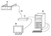
図1によりビデオシースルー型ヘッドマウントディスプレイ(HMD)の構成例を説明する。図1において、現実世界を撮像する撮像部19は撮像デバイス13および撮像光学系15などを有し、レンズとプリズムによって構成される撮像光学系15によって外部から入射する光の光束が撮像デバイス13に導かれ、光束は撮像デバイス13上に結像する。また、表示部14に表示された画像は、表示光学系(自由曲面プリズム)16によってHMDの装着者の瞳17に導かれる。つまり、装着者の瞳位置からの視線方向と略一致する現実空間の撮像を撮像部19が行い、かつ、表示部14に表示された画像を装着者の瞳17に導いて、装着者に複合現実空間画像(MR画像)を提示する。
[HMD]
A configuration example of a video see-through head mounted display (HMD) will be described with reference to FIG. In FIG. 1, an
MR画像の表示装置として、通常のモニタではなく、装着者の瞳位置からの視線とカメラの撮像方向を略一致させた撮像表示装置であるHMDを用いることで、装着者が向く方向の画像を表示部14に映し出すことができる。さらに、装着者が向いた方向のコンピュータグラフィックス(CG)画像を表示することができるため、装着者における複合現実空間への没入感を高めることが可能になる。
As an MR image display device, an image in the direction facing the wearer can be obtained by using an HMD that is an imaging display device in which the line of sight from the wearer's pupil position and the imaging direction of the camera are substantially matched, instead of a normal monitor. It can be displayed on the
[MR提示装置]
図2によりHMDを用いる複合現実感提示装置(MR提示装置)の基本構成例を説明する。図2において、HMDコントローラ11は、現実画像を撮像し、MR画像を表示するHMD10を制御する。画像処理装置20は、HMD10によって撮像された現実空間画像に仮想空間画像を重畳してMR画像を生成し、MR画像をHMDコントローラ11に供給する。HMDコントローラ11に接続された表示装置30は、装着者以外が複合現実感体験を共有する場合や装着者に提示するMR画像を確認する場合に必要になる。
[MR presentation device]
A basic configuration example of a mixed reality presentation device (MR presentation device) using HMD will be described with reference to FIG. In FIG. 2, an
図2には、HMD10とHMDコントローラ11を別体のハードウェアとした例を示すが、HMDコントローラ11をHMD10に内蔵することで、それらを一体化することができる。あるいは、HMDコントローラ11を画像処理装置20に内蔵することで、HMD10と表示装置30を画像処理装置20に直接接続することも可能である。また、詳細は後述するが、図2において、HMD10とHMDコントローラ11を接続するケーブル18が実施例の伝送制御装置に相当する。
FIG. 2 shows an example in which the
MR提示装置において、HMD10の撮像部19の視点位置が変わってもCG画像と現実空間画像を正しい位置関係で表示するために、HMD10は、視点位置や視線方向を検出するための視線位置姿勢検出部(例えば、位置姿勢センサ)を備える。
To display the CG image and the real space image in the correct positional relationship even if the viewpoint position of the
画像処理装置20は、三次元モデリングされた仮想物体を、現実空間と同じスケールの仮想空間に配置し、例えば位置姿勢センサによって検出された視点位置や視線方向から観察される仮想物体をレンダリングしてCG画像を生成する。このようにして生成したCG画像と現実空間画像を重畳することで、どのような視点位置や視線方向から観察された場合でも、現実空間の中に正しく仮想物体が配置されたMR画像を提示することができる。その結果、装着者は、HMD10を介して現実空間画像と仮想空間画像(CG画像)が重畳されたMRの世界を体験することができる。
The
HMDコントローラ11は、装着者が見ている画像と同じ画像(装着者の視点から観た画像)を、外部の表示装置30へ出力が可能な外部出力インタフェイスを有する。HMDコントローラ11は、画像処理装置20から出力される左目用画像または右目用画像の何れか一方を外部出力インタフェイスへ出力する。その結果、装着者が観察している画像を表示装置30を介して装着者以外の観衆に提供することができ、装着者が体験しているMRを観衆に同時に理解および共有させることが可能になる。
The
また、ビデオシースルー型(以下、VST型)のHMD以外にも、オプティカルシースルー型(以下、OST型)のHMDも使用される。VST型HMDにおいては、カメラで撮影した映像にCG画像を重畳して、装着者の眼前に投影するものであり、装着者は加工されたビデオ画像を観ることになる。これに対して、OST型HMDの装着者は、カメラを介さずに、ハーフミラーなどの光学系を通して現実空間画像を観るため、よりリアルな現実空間画像を観ることが可能になる。しかし、OST型HMDは、ガラス(ハーフミラーなど)を通してCG画像を投影するため、CG画像が透けているように観えることが多く、リアリティに不足を感じる場合がある。 In addition to the video see-through (hereinafter referred to as VST) HMD, an optical see-through (hereinafter referred to as OST) HMD is also used. In the VST type HMD, a CG image is superimposed on a video photographed by a camera and projected in front of the wearer's eyes, and the wearer views the processed video image. On the other hand, since the wearer of the OST type HMD views the real space image through an optical system such as a half mirror without using the camera, it is possible to view a more realistic real space image. However, since the OST type HMD projects a CG image through glass (half mirror, etc.), it often looks like the CG image is transparent, and there may be a lack of reality.
また、VST型HMDは、現実空間画像とCG画像の合成結果にばらつきが少なく、画像処理に向いている利点がある。つまり、CG描画の時間的遅れ(実写タイミングとCG描画タイミングの間のずれ)を回避するため、VST型HMDにおいては、前もって合成した映像を出力することができ、リアリティをより高めることが可能である。 In addition, the VST type HMD is advantageous in that it is suitable for image processing because there is little variation in the synthesis result of the real space image and the CG image. In other words, in order to avoid the time delay of CG drawing (deviation between live-action timing and CG drawing timing), VST type HMD can output pre-composited video, which can enhance the reality. is there.
従って、現実世界と仮想世界のシームレスな融合が可能になるため、MR提示システムには、多くの場合、VST型HMDが使われている。MR提示システム以外にも、HMDは、自動車のナビゲーション、設計・製造・生産現場、工事・建設現場、エンターテイメント、医療、教育、各種イベントを始めとして、様々な分野・用途で幅広く使用されている。 Therefore, since the real world and the virtual world can be seamlessly merged, VST type HMD is often used in MR presentation systems. In addition to the MR presentation system, HMD is widely used in various fields and applications, including automobile navigation, design / manufacturing / production sites, construction / construction sites, entertainment, medical care, education, and various events.
[接続ケーブル]
HMD10とHMDコントローラ11(またはHMDコントローラ11と画像処理装置20)の間のデータ通信に、光電変換部をコネクタに内蔵したアクティブ光ケーブル(以下、AOC)を用いる。さらに、HMDへの電源供給や動作状態の監視などのために、AOCに複数の電線を組み合わせた光電気複合ケーブルを使用する。
[Connection cable]
For data communication between the
このような光電気複合ケーブルの利用により、撮像画像と表示画像を光通信によって送受信することができ、高い転送レート(例えば5-10Gbps程度)と長距離伝送(例えば10-30m程度)の両方を実現する。光電変換部を内蔵したAOCの利用により、コネクタの嵌合部はメタルケーブルとほぼ同等の扱いでよく、HMDの使用者によるケーブルの自由な着脱作業が可能になり、例えば、摩耗等によりケーブルの交換が必要になった場合もケーブルの交換は容易である。 By using such a photoelectric composite cable, captured images and display images can be transmitted and received by optical communication, and both high transfer rate (for example, about 5-10 Gbps) and long-distance transmission (for example, about 10-30 m) can be achieved. Realize. The use of AOC with a built-in photoelectric conversion unit allows the connector fitting part to be handled almost the same as a metal cable, allowing the HMD user to freely attach and remove the cable. Cable replacement is easy even when replacement is necessary.
さらに、HMDの動作状態を外部に通知するための動作状態監視用の制御線を用いて光電変換部の出力を制御することで、HMDの内部において電源供給が停止されている際に、通信用ICに不定な信号が入力されることを防止することができる。つまり、簡易な制御回路によって不定な信号が通信用ICに入力されることを防ぎ、バッテリレスかつ省配線な構成のHMDを可能にして、光電気複合ケーブルが切断された場合も確実に光出力を停止させることができる。 Furthermore, by controlling the output of the photoelectric conversion unit using an operation state monitoring control line for notifying the operation state of the HMD to the outside, when the power supply is stopped inside the HMD, it is used for communication It is possible to prevent an indefinite signal from being input to the IC. In other words, a simple control circuit prevents undefined signals from being input to the communication IC, enables battery-less and wiring-saving HMD, and ensures reliable optical output even when the photoelectric composite cable is disconnected Can be stopped.
[MR提示装置の構成]
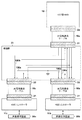
図3により実施例1のMR提示装置の構成例を説明する。光電気複合ケーブル18を介して、VSD型HMD10とHMDコントローラ11が接続され、MR提示装置が構成される。HMDコントローラ11は、画像処理装置20から分離した状態で存在してもよいし、画像処理装置20に内蔵されていてもよい。なお、以下ではVSD型HMD10を単に「HMD10」と呼ぶ。
[Configuration of MR presentation device]
A configuration example of the MR presentation device according to the first embodiment will be described with reference to FIG. The
光電気複合ケーブル18の端部に相当するコネクタ22には光電変換回路104aが組み込まれ、コネクタ21には光電変換回路104bが組み込まれ、光電気複合ケーブル18はHMD10と外部装置の間のインタフェイスケーブルとして機能する。なお、図3に示すHMD10の構成は、主にHMDコントローラ11とのインタフェイス部のみを抜粋したものである。
The
HMD10の通信用IC1011は、複数のデータと制御信号を入出力するための複数の入出力(I/O)ポートを有する。I/Oポートには上述した撮像部19と表示部14が接続され、通信用IC1011は、撮像部19の撮像によって取得された映像データを入力し、表示すべき映像データを表示部14に出力する。
The
また、I/Oポートには送信信号線Tx0とTx1、および、受信信号線Rx0とRx1が接続され、撮像された映像データと制御信号が送信信号線Tx0とTx1を介して光電変換回路104aの変換部1041に送信される。また、受信信号線Rx0とRx1を介して、表示すべき映像データと制御信号を光電変換回路104aの変換部1041から受信する。送信信号線Tx0とTx1、および、受信信号線Rx0とRx1は、パラレル信号線でもシリアル信号線でもよく、シングルエンド方式でも差動方式でもよい。
In addition, transmission signal lines Tx0 and Tx1 and reception signal lines Rx0 and Rx1 are connected to the I / O port, and the captured video data and control signals are transmitted to the
図3には、光ファイバ105を送信用の伝送系に二本、受信用の伝送系に二本、合計四本使用する例を示すが、光ファイバ105の数は任意である。HMD10の撮像部19に例えば複数の撮像デバイス19a、19bが存在する場合、それら撮像デバイス19a、19bからの映像データを多重化し、一本または複数本の光ファイバを用いてHMDコントローラ11に送信することが可能である。同様に、HMD10の表示部14に例えば複数に表示デバイス14a、14bが存在する場合、それら表示デバイス14a、14bへ供給する映像データを多重化し、一本または複数本の光ファイバを用いてHMDコントローラ11から送信することが可能である。映像データの多重化と同様に、光ファイバを通過する信号には、位置姿勢センサの信号を含む各種制御信号を多重化することができ、信号線の数を減らすことが可能である。
FIG. 3 shows an example in which two
HMD10には、HMD10の各部への電源供給を開始または終了させるための電源スイッチ(図示無し)がある。HMD10が非動作時に電源スイッチが押される(以下、電源オン)と、HMD10の各部への電源供給が開始され、HMD10が起動する。逆に、HMD10が動作時に電源スイッチが押される(以下、電源オフ)と、HMD10の各部への電源供給が停止され、HMD10の動作が終了する。
The
HMD10には、光電気複合ケーブル18を介して、HMDコントローラ11(または画像処理装置20)から外部電源(例えばDC12V)が供給される。電源オン時、レギュレータ(図示無し)が、外部電源から降圧した内部電源(例えばDC3.3V)をHMD10の各部に供給する。
An external power supply (for example, DC 12 V) is supplied to the
制御信号CNTの信号線(以下、制御信号線)106は、レジスタ1015(例えば1kΩ)によって内部電源ラインにプルアップされている。なお、制御信号線106は電線であり、外来ノイズを受けても容易に制御信号CNTのレベルが変化しないようにする必要がある。そのため、制御信号線106には、ノイズ対策部品(ツェナダイオードやバリスタ等)を接続したり、制御信号CNTを入力する通信用IC1011の内部でフィルタリング処理などが行われる。
A signal line (hereinafter, control signal line) 106 for the control signal CNT is pulled up to an internal power supply line by a register 1015 (for example, 1 kΩ). Note that the
また、制御信号線106は、通信用IC1011のノーマルクローズでグラウンドに接続される出力端子に接続されている。従って、レギュレータによる内部電源の供給が開始された直後、制御信号CNTの状態はローレベル(非アクティブ)に維持される。その後、通信用IC1011によって当該出力端子がオープンにされた時点で、制御信号CNTの状態がハイレベル(アクティブ)になる。例えば、HMD10の内部電源の供給が開始され、通信用IC1011が通信準備段階にある場合、通信用IC1011によって制御信号CNTの状態が非アクティブに維持される。その後、通信可能な状態となると、通信用IC1011は、制御信号CNTの状態をアクティブにする。
The
通信準備段階とは、例えば、外部ROMから通信用IC1011へプログラムを書込中など、通常の動作を行う前段階のことである。また、撮像部19の初期化時、アイドリング時、エラー発生時など、撮像部19から映像データを通信用IC1011が受信していない状態なども通信が不可能な状態に含まれる。また、表示部14の初期化時、アイドリング時、エラー発生時など、通信用IC1011から映像データを受信した表示部14が表示を行えない状態なども通信が不可能な状態に含まれる。
The communication preparation stage is a stage before normal operation such as writing a program from the external ROM to the
また、複数の撮像部19の映像データを一本の光ファイバで送信する場合は、少なくとも一つの撮像部19が通常の動作を行える状態にあれば通信を開始してもよい。その場合、通常の動作時よりも信号速度を落としてもよい。同様に、複数の表示部14の映像データを一本の光ファイバで送信する場合は、少なくとも一つの表示部14が通常の動作を行える状態であれば通信を開始してもよい。その場合、通常の動作時よりも信号速度を落としてもよい。
In addition, when video data of a plurality of
HMD10と光電気複合ケーブル18はコネクタ22によって接続され、光電気複合ケーブル18とHMDコントローラ11はコネクタ21によって接続される。それらコネクタ21、22には、挿抜耐久性が高い機器間接続に適したインタフェイス用コネクタを用いること好ましいが、その他のコネクタを用いてもよい。なお、図3には、コネクタ21、22を介して、Tx0などの送受信信号線および制御信号線106を接続する例を示す。また、図示しないが、電源線およびグラウンド線をコネクタ21、22を介して接続してもよい。勿論、Tx0などの送受信信号線用のコネクタと、制御信号線106、外部電源線およびグラウンド線用のコネクタに分離して、それらコネクタの挿抜が略同時に行われるようにしてもよい。
The
光電変換回路104a、104bはそれぞれ、光信号→電気信号の変換、および、電気信号→光信号の変換を行う変換部1041、各種設定および制御を行うCPU(図示無し)、変換部1041などに内部電源を供給するレギュレータなどから構成される。
Each of the
図3に示すHMDコントローラ11の構成は、主にHMD10とのインタフェイス部のみを抜粋したものである。HMDコントローラ11の通信用IC1111は、複数のデータと制御信号を入出力するための複数のI/Oポートを有する。I/Oポートには送信信号線Tx0とTx1、および、受信信号線Rx0とRx1が接続され、表示すべき映像データと制御信号が送信信号線Tx0とTx1を介して光電変換回路104bの変換部1041に送信される。また、受信信号線Rx0とRx1を介して、撮像された映像データと制御信号を光電変換回路104bの変換部1041から受信する。前述したように、送信信号線Tx0とTx1、および、受信信号線Rx0とRx1は、パラレル信号線でもシリアル信号線でもよく、シングルエンド方式でも差動方式でもよい。
The configuration of the
また、制御信号線106は、通信用IC1111の入力端子に接続され、光電気複合ケーブル18が未接続時の入力保護としてレジスタ1115によりグラウンド電位にプルダウンされている。なお、レジスタ1115の抵抗値は、制御信号CNTの状態を確実にアクティブにすることができるように、レジスタ1015の抵抗値の十倍以上(例えば10kΩ)にすることが望ましい。
The
[光電変換回路の動作]
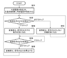
図4のフローチャートにより光電変換回路104a、104bの動作を説明する。図4に示す動作は、HMDコントローラ11の起動により開始される。なお、HMDコントローラ11は画像処理装置20の起動に連動して起動されるものとする。
[Operation of photoelectric conversion circuit]
The operation of the
HMDコントローラ11が起動すると、電源線を介して光電変換回路104a、104b、HMD10に電源が供給され、レギュレータにより外部電源から降圧された内部電源の変換部1041への供給が開始される(S11)。動作を開始した変換部1041は、制御信号CNTの状態を判定する(S12)。この時点ではHMD10が電源オンになっていないため、制御信号CNTの状態は非アクティブであり、変換部1041は、光信号および電気信号の出力を行わない待機状態になり(S13)、動作はステップS12に戻る。つまり、HMD10の電源スイッチが押されるまで、ステップS12とS13の動作が繰り返される。
When the
電源スイッチが押されると、レギュレータにより外部電源から降圧された内部電源のHMD10の各部への供給が開始される(電源オン)。電源オン後、例えば、通信用IC1011が通信可能な状態になると、制御信号CNTの状態がアクティブになり、動作はステップS12からS14に遷移する。制御信号CNTの状態がアクティブになると、変換部1041は、光信号および電気信号の出力を開始して動作状態になり(S14)、HMD10が使用可能になる。
When the power switch is pressed, supply of the internal power source, stepped down from the external power source by the regulator, to each part of the
動作状態になった後、変換部1041は、制御信号CNTの状態を判定し(S15)、制御信号CNTの状態がアクティブの場合はステップS15の判定を繰り返す。再び、電源スイッチが押されると、レギュレータにより外部電源から降圧された内部電源のHMD10の各部への供給が停止し(電源オフ)、制御信号CNTの状態が非アクティブになり、動作はステップS15からS16に遷移する。制御信号CNTの状態が非アクティブになると、変換部1041は、光信号および電気信号の出力を停止し(S16)、動作はステップS12に戻る。
After entering the operating state, the
なお、HMDコントローラ11が電源オフになるなどにより、内部電源線を介した光電変換回路104a、104b、HMD10への電源の供給が停止され、図4に示す動作は終了する。
Note that the power supply to the
HMDコントローラ11が動作中、変換部1041が図4に示す動作を行うことで、HMD10が電源オフの状態において通信用IC1011に不定な信号が入力されることを防ぐことができる。また、光電変換回路104a、104bへの内部電源の供給が遮断されないため、HMD10だけが電源オフから電源オンに遷移される場合の、MR提示装置に復帰時間を軽減することができる。また、光電気複合ケーブル18が切断された場合、HMDコントローラ11からHMD10への外部電源の供給が遮断されるため制御信号CNTの状態が非アクティブになり、光信号および電気信号の出力が停止される。
When the
このように、光電変換回路104a、104bを備える光電気複合ケーブル18は、制御信号CNTの状態に応じて、光信号と電気信号の出力を制御して、光ファイバ105を介した伝送を制御する、ケーブル状の形態を有する伝送制御装置として機能する。
As described above, the photoelectric
[変形例]
送信用および受信用それぞれに複数の光ファイバを使用すれば、故障に対して、光ファイバの切替制御が可能になる。例えば、各光ファイバによって、所定の周期で、固定パターンのデータを伝送し、固定パターンに一致するデータが受信されたか否かを判定する。ある光ファイバで固定データに一致しないデータの受信が多発した場合、当該光ファイバの系統に故障が発生したと判断して、残りの光ファイバを使用してデータ通信を継続する。その際、必要があれば、正常時よりも低解像度の映像データを転送する。このようにすれば、ケーブルなどの故障により、MR提示装置が急に使用不能になる問題を回避することができる。
[Modification]
If a plurality of optical fibers are used for transmission and reception, switching control of optical fibers can be performed against a failure. For example, each optical fiber transmits fixed pattern data at a predetermined cycle, and determines whether or not data matching the fixed pattern is received. When reception of data that does not match fixed data frequently occurs in a certain optical fiber, it is determined that a failure has occurred in the optical fiber system, and data communication is continued using the remaining optical fiber. At that time, if necessary, video data having a lower resolution than normal is transferred. In this way, it is possible to avoid a problem that the MR presentation device suddenly becomes unusable due to a failure of a cable or the like.
また、故障診断を定期的に行わずに、電源オンの直後など不定期に行ってもよい。勿論、故障が発生したと判断するデータ不一致の数(判定基準)や、固定パターンについては任意に設定することができる。 Further, the failure diagnosis may not be performed periodically but may be performed irregularly such as immediately after the power is turned on. Of course, the number of data mismatches (determination criteria) for determining that a failure has occurred and a fixed pattern can be arbitrarily set.
以下、本発明にかかる実施例2の伝送制御装置およびその制御方法を説明する。なお、実施例2において、実施例1と略同様の構成については、同一の符号を付して、その詳細な説明を省略する場合がある。 The transmission control apparatus and control method according to the second embodiment of the present invention will be described below. Note that the same reference numerals in the second embodiment denote the same parts as in the first embodiment, and a detailed description thereof may be omitted.
撮像画像に重畳するCG画像のデータ量が大きいと、画像処理装置20の一台当りの処理能力ではリアルタイム性を損なう場合があり、一台のHMD10に複数の画像処理装置20b、20cから映像データを供給する方法が利用される。例えば、一台目の画像処理装置20bが左目用画像を生成し、二台目の画像処理装置20cが右目用画像を生成することで、リアルタイム性を改善する。実施例2では、一台のHMD10に二台の画像処理装置20b、20cから映像データを供給するMR提示装置を説明する。
If the amount of CG image data to be superimposed on the captured image is large, the processing capability per
図5により実施例2のMR提示装置の構成例を説明する。実施例2のMR提示装置においては、複数の光電気複合ケーブル18a、18b、18cを介して、一台のHMD10と二台のHMDコントローラ11b、11cが接続される。各HMDコントローラ11b、11cは、対応する画像処理装置20b、20cから分離した状態で存在してもよいし、対応する画像処理装置20b、20cに内蔵されていてもよい。
A configuration example of the MR presentation device according to the second embodiment will be described with reference to FIG. In the MR presentation device according to the second embodiment, one
図5に示すように、HMD10に接続された光電気複合ケーブル18aの他端は接続部23に接続される。接続部23は、二本の光電気複合ケーブル18b、18cによって二台のHMDコントローラ11b、11cに接続される。図には示さないが、例えば、HMDコントローラ11bが光電気複合ケーブル18a、18bおよびHMD10に外部電源を供給し、HMDコントローラ11cが光電気複合ケーブル18cに外部電源を供給する。勿論、HMDコントローラ11cが光電気複合ケーブル18aとHMD10にも外部電源を供給してもよい。
As shown in FIG. 5, the other end of the optical / electrical
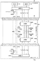
図6により実施例2におけるHMD10、光電気複合ケーブル18a、HMDコントローラ11bの構成例を示す。なお、説明を容易にするために、図6においては接続部23、光電気複合ケーブル18b、18c、HMDコントローラ11cの記載を省略するが、コネクタ21の接続対の間に接続部23が入ると理解されたい。また、光電気複合ケーブル18a、18b、18cは同様の構成を有し、HMDコントローラ11b、11cも同様の構成を有する。
FIG. 6 shows a configuration example of the
図3に示した構成と異なり、二つの制御信号CNTb、CNTcを伝送するために二本の制御信号線106b、106cがある。そして、変換部1041が制御信号の状態を判定するために、二つの制御信号CNTb、CNTcの状態の論理和をとるためのORゲート1044が各光電変換回路104a、104bに追加される。
Unlike the configuration shown in FIG. 3, there are two
図6には二つの制御信号CNTbとCNTcの両方がHMDコントローラ11bの通信用IC1111に入力されるように記載するが、接続部23により、一部の制御信号CNTbだけがHMDコントローラ11bの通信用IC1111に入力される。つまり、図5に示すように、接続部23によって、一部の制御信号CNTbがHMDコントローラ11bに分配され、一部の制御信号CNTcがHMDコントローラ11cに分配される。
FIG. 6 shows that both control signals CNTb and CNTc are input to the
同様に、図6にはHMDコントローラ11cの送信信号線Tx0とTx1の両方が光電気複合ケーブル18aに接続されるように記載するが、接続部23により、一部の送信信号線Tx0だけが光電気複合ケーブル18aに接続される。つまり、図5に示すように、接続部23によって、HMDコントローラ11bの一部の送信信号線Tx0が光電気複合ケーブル18aに接続され、HMDコントローラ11cの一部の送信信号線Tx1が光電気複合ケーブル18aに接続される。また、HMDコントローラ11bの送信信号線Tx1とHMDコントローラ11cの送信信号線Tx0は、接続部23によって、オープンになる。従って、表示部14に、例えば、HMDコントローラ11bから供給される映像データを左目用画像として表示し、HMDコントローラ11cから供給される映像データを右目用画像として表示することができる。
Similarly, FIG. 6 shows that both the transmission signal lines Tx0 and Tx1 of the HMD controller 11c are connected to the photoelectric
一方、撮像された映像データは二台の画像処理装置20b、20cに供給する必要があるため、HMDコントローラ11bの受信信号線Rx0とRx1の両方が光電気複合ケーブル18aに接続される。同様に、HMDコントローラ11cの受信信号線Rx0とRx1の両方も光電気複合ケーブル18aに接続される。
On the other hand, since the captured video data needs to be supplied to the two
HMD10の通信用IC1011は、各制御信号CNTb、CNTcの状態を制御可能である。例えば、左目用画像の表示部14は通常動作状態にあるが、右目用画像の表示部14が初期化時、アイドリング時、エラー発生時などの場合、制御信号CNTbの状態をアクティブ、制御信号CNTcの状態を非アクティブにする。この場合、右目用画像の映像データを伝送する光電気複合ケーブル18cの光電変換回路104a、104bは出力停止状態になる。一方、左目用画像の映像データを伝送する光電気複合ケーブル18bの光電変換回路104a、104bは動作状態を維持する。勿論、光電気複合ケーブル18aの光電変換回路104a、104bも動作状態を維持する。
The
このように、実施例2においては、接続部23と、接続部23に接続された複数の光電気複合ケーブル18の集合が伝送制御装置を構成する。
Thus, in the second embodiment, the
[変形例]
図5には、接続部23により、制御信号の一方をHMDコントローラ11に接続する例を示したが、両方の制御信号をHMDコントローラ11に接続することもできる。同様に、接続部23により、送信信号線の一方をHMDコントローラ11に接続する例を示したが、両方の送信信号線をHMDコントローラ11に接続することもできる。その場合、HMD10の通信用IC1011によって制御信号の状態の組み合わせを制御することにより、各画像処理装置20b、20cの動作を制御することが可能である。
[Modification]
Although FIG. 5 shows an example in which one of the control signals is connected to the
図7により複数の制御信号の状態の組み合わせと複数の画像処理装置20b、20cの動作の関係を説明する。なお、‘H’は制御信号の状態がアクティブ(ハイレベル)、‘L’は制御信号の状態が非アクティブ(ローレベル)を示す。
The relationship between the combination of the states of the plurality of control signals and the operations of the plurality of
二つの制御信号の状態がともに‘H’の場合は一方の画像処理装置20bが両目用の映像データを生成し、他方の画像処理装置20cにおける映像データの生成は休止する。CNTbの状態が‘H’、CNTcの状態が‘L’の場合は一方の画像処理装置20bが左目用の映像データを生成し、他方の画像処理装置20cが右目用の映像データを生成する。CNTbの状態が‘L’、CNTcの状態が‘H’に反転すると、一方の画像処理装置20bが右目用の映像データを生成し、他方の画像処理装置20cが左目用の映像データを生成する。
When both of the two control signals are “H”, one
勿論、二つの制御信号の状態がともに‘L’の場合は両方の画像処理装置20b、20cにおける映像データの生成が休止する。なお、例えば、両目用または左目用の映像データを生成する画像処理装置20b側から電源を供給するように制御することもできる。
Of course, when both of the two control signals are “L”, the generation of the video data in both the
例えば、装着者が操作可能なスイッチをHMD10に配置する。通信用IC1011は、当該スイッチの状態によって制御信号の状態を切り替える。装着者は、一台の画像処理装置20bではリアルタイム性が不足すると感じる場合、当該スイッチを操作して、二台の画像処理装置20cに映像データを生成させることができる。さらに、左右の画像が逆に表示されていると感じた場合、装着者は、当該スイッチを操作して左右の画像を切り替えて左右の画像が正しく供給されているか否かを判断し、正しい表示状態を得ることができる。
For example, a switch that can be operated by the wearer is arranged on the
10 … 撮像表示装置、18 … 伝送制御装置、20 … 画像処理装置 10… Imaging display device, 18… Transmission control device, 20… Image processing device
Claims (18)
前記映像データを表す電気信号から変換した光信号を出力する第一の変換手段、前記光信号を伝送するための光ファイバ、および、前記光ファイバによって伝送される前記光信号を変換した電気信号を出力する第二の変換手段を有する伝送手段と、
前記撮像表示装置の通信手段が前記映像データの通信が可能か否かを示す制御信号を伝送するための電線とを有し、
前記制御信号に基づき、前記第一および第二の変換手段の動作が制御される伝送制御装置。 A transmission control device for transmitting video data acquired by imaging of an imaging display device having imaging means and display means to an image processing device, and transmitting video data generated by the image processing device to the imaging display device. ,
First conversion means for outputting an optical signal converted from an electrical signal representing the video data, an optical fiber for transmitting the optical signal, and an electrical signal obtained by converting the optical signal transmitted by the optical fiber Transmission means having second conversion means for outputting;
The communication means of the imaging display device has an electric wire for transmitting a control signal indicating whether communication of the video data is possible,
A transmission control apparatus in which operations of the first and second conversion units are controlled based on the control signal.
前記第一の伝送系において、前記複数の撮像部によって撮像された映像データが多重化され、前記撮像部の数よりも少ない数の光ファイバを使用して前記多重化された映像データが伝送される請求項6に記載された伝送制御装置。 The imaging means has a plurality of imaging units,
In the first transmission system, the video data captured by the plurality of imaging units is multiplexed, and the multiplexed video data is transmitted using a smaller number of optical fibers than the number of the imaging units. The transmission control device according to claim 6.
前記第二の伝送系において、前記複数の表示部へ供給される映像データが多重化され、前記表示部の数よりも少ない数の光ファイバを使用して前記多重化された映像データが伝送される請求項6または請求項7に記載された伝送制御装置。 The display means has a plurality of display units,
In the second transmission system, video data supplied to the plurality of display units is multiplexed, and the multiplexed video data is transmitted using a smaller number of optical fibers than the number of the display units. 8. The transmission control device according to claim 6 or claim 7.
前記映像データを表す電気信号から変換した光信号を出力する第一の変換手段、前記光信号を伝送するための光ファイバ、および、前記光ファイバによって伝送される前記光信号から変換した電気信号を出力する第二の変換手段を有する伝送手段と、
第一および第二の制御信号を伝送するための複数の電線とを有し、
前記第一および第二の制御信号の少なくとも一つに基づき、前記第一および第二の変換手段の動作が制御される伝送制御装置。 Video data acquired by imaging of an imaging display device having imaging means and display means is transmitted to a plurality of image processing devices, and video data generated by at least one of the plurality of image processing devices is transmitted to the imaging display device. A transmission control device for transmitting,
First conversion means for outputting an optical signal converted from an electrical signal representing the video data, an optical fiber for transmitting the optical signal, and an electrical signal converted from the optical signal transmitted by the optical fiber Transmission means having second conversion means for outputting;
A plurality of electric wires for transmitting the first and second control signals;
A transmission control device in which operations of the first and second conversion means are controlled based on at least one of the first and second control signals.
前記映像データを表す電気信号を変換した光信号を出力する第一の変換手段、前記光信号を伝送するための光ファイバ、および、前記光ファイバによって伝送される前記光信号を変換した電気信号を出力する第二の変換手段を有する伝送手段と、
前記撮像表示装置の通信手段が前記映像データの通信が可能か否かを示す制御信号を伝送するための電線とを有し、
前記制御信号に基づき、前記第一および第二の変換手段の動作を制御する制御方法。 A control method of a transmission control device for transmitting video data acquired by imaging of an imaging display device having imaging means and display means to an image processing device, and transmitting video data generated by the image processing device to the imaging display device And the transmission control device comprises:
First conversion means for outputting an optical signal obtained by converting an electrical signal representing the video data, an optical fiber for transmitting the optical signal, and an electrical signal obtained by converting the optical signal transmitted by the optical fiber Transmission means having second conversion means for outputting;
The communication means of the imaging display device has an electric wire for transmitting a control signal indicating whether communication of the video data is possible,
A control method for controlling operations of the first and second conversion means based on the control signal.
前記映像データを表す電気信号から変換した光信号を出力する第一の変換手段、前記光信号を伝送するための光ファイバ、および、前記光ファイバによって伝送される前記光信号から変換した電気信号を出力する第二の変換手段を有する伝送手段と、
第一および第二の制御信号を伝送する複数の電線とを有し、
前記第一および第二の制御信号の少なくとも一つに基づき、前記第一および第二の変換手段の動作を制御する制御方法。 Video data acquired by imaging of an imaging display device having imaging means and display means is transmitted to a plurality of image processing devices, and video data generated by at least one of the plurality of image processing devices is transmitted to the imaging display device. A transmission control device control method for transmitting, wherein the transmission control device comprises:
First conversion means for outputting an optical signal converted from an electrical signal representing the video data, an optical fiber for transmitting the optical signal, and an electrical signal converted from the optical signal transmitted by the optical fiber Transmission means having second conversion means for outputting;
A plurality of electric wires for transmitting the first and second control signals;
A control method for controlling operations of the first and second conversion means based on at least one of the first and second control signals.
Priority Applications (2)
| Application Number | Priority Date | Filing Date | Title |
|---|---|---|---|
| US15/540,706 US10638088B2 (en) | 2015-03-03 | 2016-01-22 | Transfer control apparatus, control method, and mixed-reality presentation apparatus |
| PCT/JP2016/000316 WO2016139882A1 (en) | 2015-03-03 | 2016-01-22 | Transfer control apparatus, control method, and mixed-reality presentation apparatus |
Applications Claiming Priority (2)
| Application Number | Priority Date | Filing Date | Title |
|---|---|---|---|
| JP2015041776 | 2015-03-03 | ||
| JP2015041776 | 2015-03-03 |
Publications (2)
| Publication Number | Publication Date |
|---|---|
| JP2016167794A true JP2016167794A (en) | 2016-09-15 |
| JP2016167794A5 JP2016167794A5 (en) | 2019-01-10 |
Family
ID=56898880
Family Applications (1)
| Application Number | Title | Priority Date | Filing Date |
|---|---|---|---|
| JP2015228095A Pending JP2016167794A (en) | 2015-03-03 | 2015-11-20 | Transmission control device and control method, and mixed reality presentation device |
Country Status (2)
| Country | Link |
|---|---|
| US (1) | US10638088B2 (en) |
| JP (1) | JP2016167794A (en) |
Cited By (3)
| Publication number | Priority date | Publication date | Assignee | Title |
|---|---|---|---|---|
| JP2018148495A (en) * | 2017-03-08 | 2018-09-20 | マスプロ電工株式会社 | Cable unit |
| JPWO2021040047A1 (en) * | 2019-08-29 | 2021-03-04 | ||
| WO2021040049A1 (en) * | 2019-08-29 | 2021-03-04 | 株式会社フジクラ | Transmitter, receiver, and communication system |
Families Citing this family (2)
| Publication number | Priority date | Publication date | Assignee | Title |
|---|---|---|---|---|
| JP2018141874A (en) * | 2017-02-28 | 2018-09-13 | セイコーエプソン株式会社 | Head-mounted display device and image forming optical system |
| CN113176669B (en) * | 2021-04-22 | 2022-07-22 | 歌尔股份有限公司 | Display system, display glasses and display system control method |
Family Cites Families (7)
| Publication number | Priority date | Publication date | Assignee | Title |
|---|---|---|---|---|
| JP2001160777A (en) | 1999-12-01 | 2001-06-12 | Furukawa Electric Co Ltd:The | Data communication controller |
| JP2004179733A (en) | 2002-11-25 | 2004-06-24 | Japan Aviation Electronics Industry Ltd | Luminous quantity adjustment apparatus of light source for supplying optical signal used for photoelectric composite communication system |
| JP2007306213A (en) | 2006-05-10 | 2007-11-22 | Fuji Xerox Co Ltd | Power supply controller of optical module, and optical communication system |
| JP5417151B2 (en) * | 2009-12-18 | 2014-02-12 | 株式会社東芝 | Optical wiring cable and optical power control method |
| JP5023190B2 (en) * | 2010-06-10 | 2012-09-12 | Nttエレクトロニクス株式会社 | Video transmission system |
| WO2012105440A1 (en) | 2011-02-04 | 2012-08-09 | 株式会社フジクラ | Power source control system, active cable, power source control device, connector set, and power source control method |
| JP5769751B2 (en) | 2013-03-29 | 2015-08-26 | キヤノン株式会社 | Image processing apparatus, image processing method, and program |
-
2015
- 2015-11-20 JP JP2015228095A patent/JP2016167794A/en active Pending
-
2016
- 2016-01-22 US US15/540,706 patent/US10638088B2/en active Active
Cited By (6)
| Publication number | Priority date | Publication date | Assignee | Title |
|---|---|---|---|---|
| JP2018148495A (en) * | 2017-03-08 | 2018-09-20 | マスプロ電工株式会社 | Cable unit |
| JPWO2021040047A1 (en) * | 2019-08-29 | 2021-03-04 | ||
| WO2021040049A1 (en) * | 2019-08-29 | 2021-03-04 | 株式会社フジクラ | Transmitter, receiver, and communication system |
| WO2021040047A1 (en) * | 2019-08-29 | 2021-03-04 | 株式会社フジクラ | Transmitter, receiver, and communication system |
| JPWO2021040049A1 (en) * | 2019-08-29 | 2021-03-04 | ||
| CN114223153A (en) * | 2019-08-29 | 2022-03-22 | 株式会社藤仓 | Transmitter, receiver, and communication system |
Also Published As
| Publication number | Publication date |
|---|---|
| US10638088B2 (en) | 2020-04-28 |
| US20180007312A1 (en) | 2018-01-04 |
Similar Documents
| Publication | Publication Date | Title |
|---|---|---|
| JP2016167794A (en) | Transmission control device and control method, and mixed reality presentation device | |
| US20150168729A1 (en) | Head mounted display device | |
| JP3979300B2 (en) | Interface module for digital video signal transmission | |
| TWI615631B (en) | Head-mounted display device and control method of head-mounted display device | |
| EP3211602B1 (en) | Head-mounted type display device and method for controlling same, and computer program | |
| US9792710B2 (en) | Display device, and method of controlling display device | |
| US20150097873A1 (en) | Head-mounted display device and control method for the head-mounted display device | |
| US10613333B2 (en) | Head-mounted display device, computer program, and control method for head-mounted display device | |
| CN109075565B (en) | Enabling of device power-on with appropriate components | |
| JP7243193B2 (en) | Display system, display system control method, information processing device, and information processing device control program | |
| KR20150070108A (en) | Cable, electronic device, and method for controlling electronic device | |
| WO2022222383A1 (en) | Display system, display glasses, and display system control method | |
| US20150168728A1 (en) | Head mounted display device | |
| CN113050907A (en) | Image display device, power feeding system, and power feeding method for image display device | |
| WO2016139882A1 (en) | Transfer control apparatus, control method, and mixed-reality presentation apparatus | |
| CN101916034A (en) | Camera device and three-dimensional image display system using same | |
| EP3223528B1 (en) | Device for transmitting or receiving video, method for controlling device, and computer program | |
| WO2017081914A1 (en) | Adaptor device and imaging apparatus | |
| CN102998799A (en) | Near-to-eye display system for blending virtual with real scenes | |
| WO2014119007A1 (en) | Sight line detection device | |
| CN220271669U (en) | Vehicle-mounted AR (augmented reality) glasses assembly | |
| CN109901294B (en) | Head-mounted display system | |
| JPH08322065A (en) | Stereoscopic image device | |
| CN108594430A (en) | A kind of wear-type TV | |
| CN116456042A (en) | Digital glasses for short-distance AR/VR wireless image transmission technology head display and execution method |
Legal Events
| Date | Code | Title | Description |
|---|---|---|---|
| A521 | Request for written amendment filed |
Free format text: JAPANESE INTERMEDIATE CODE: A523 Effective date: 20181119 |
|
| A621 | Written request for application examination |
Free format text: JAPANESE INTERMEDIATE CODE: A621 Effective date: 20181119 |
|
| A131 | Notification of reasons for refusal |
Free format text: JAPANESE INTERMEDIATE CODE: A131 Effective date: 20190802 |
|
| A521 | Request for written amendment filed |
Free format text: JAPANESE INTERMEDIATE CODE: A523 Effective date: 20191001 |
|
| A02 | Decision of refusal |
Free format text: JAPANESE INTERMEDIATE CODE: A02 Effective date: 20200117 |