JP2016165594A - Game machine - Google Patents
Game machine Download PDFInfo
- Publication number
- JP2016165594A JP2016165594A JP2016122701A JP2016122701A JP2016165594A JP 2016165594 A JP2016165594 A JP 2016165594A JP 2016122701 A JP2016122701 A JP 2016122701A JP 2016122701 A JP2016122701 A JP 2016122701A JP 2016165594 A JP2016165594 A JP 2016165594A
- Authority
- JP
- Japan
- Prior art keywords
- screw
- breaking screw
- ball
- game
- control board
- Prior art date
- Legal status (The legal status is an assumption and is not a legal conclusion. Google has not performed a legal analysis and makes no representation as to the accuracy of the status listed.)
- Pending
Links
Images


Abstract
Description
本発明は、パチンコ機やスロットマシンに代表される遊技機に関するものである。 The present invention relates to gaming machines represented by pachinko machines and slot machines.
パチンコ球を使用するパチンコ機等の遊技機においては、不正な利益を得ることを目的
として、例えば、遊技を統括制御する主制御基板等の制御基板を不正に取り外して当該基
板内のROM(CPUやROMが1チップ化されている場合は当該チップ)を交換し遊技
内容を変更するといった不正行為がなされることがある。
In a gaming machine such as a pachinko machine using a pachinko ball, for example, for the purpose of obtaining an illegal profit, for example, a control board such as a main control board that controls the game is illegally removed and a ROM (CPU In the case where the ROM is made into one chip, an illegal act such as exchanging the chip) and changing the game content may be performed.
このため、制御基板を収容した基板ボックスを、破断ネジと称される特殊なネジを用い
て閉塞したり、あるいは基板ボックスをこの破断ネジで所定位置に取り付けたりするよう
にし、これにより不正行為を防止することがなされている。破断ネジは、頭部の中間部に
小径の破断部が形成された構成を有し、ドライバでネジ孔に螺入して締結した後、さらに
大きいトルクで回転させると、破断部より先端側の、ドライバを嵌入するネジ穴を有する
部分が破断して分離し、したがって以降はネジを逆回しして緩めることができなくなるよ
うになっている。上記基板ボックスの閉塞や取付にこの破断ネジを用いることにより、基
板ボックスを開封することや取り外すことを困難とすることができ、したがって効果的に
不正行為を防止することができる。
上記のような破断ネジを用いた遊技機としては、例えば、以下の文献に記載のものが挙
げられる。
For this reason, the board box containing the control board is closed with a special screw called a breaking screw, or the board box is attached to a predetermined position with the breaking screw, thereby preventing illegal acts. It has been made to prevent. The breaking screw has a configuration in which a small-diameter breaking portion is formed in the middle portion of the head, and after screwing into the screw hole with a screwdriver and fastening it, when rotated with a larger torque, the breaking screw is located on the tip side from the breaking portion. The part having the screw hole for inserting the screwdriver is broken and separated, so that the screw cannot be subsequently loosened by rotating it backward. By using this breaking screw for closing or attaching the substrate box, it is difficult to open or remove the substrate box, and therefore, illegal acts can be effectively prevented.
Examples of the gaming machine using the above breaking screw include those described in the following documents.
しかしながら、上記のような破断ネジは、破断しやすい破断部が形成されたものである
ため、例えば特に、締結作業を行う前に一箇所に多量にまとめて置かれている間などに、
何らかの外力を受けて当該破断部が破断してしまい、締結に使用される前にネジとして使
い物にならなくなってしまう(以下、このような事態を「誤破断」とも称す)といった恐
れがある。
However, since the rupture screw as described above is formed with a rupture portion that is easy to rupture, for example, especially during being placed in a large amount in one place before fastening work,
There is a risk that the rupture portion will be broken by receiving some external force and become unusable as a screw before being used for fastening (hereinafter, this situation is also referred to as “false break”).
そこで、例えば破断ネジを使用時までは硬質のケース等に収納しておくようにして誤破
断を防止することも考えられるが、これによれば、破断ネジを使用時にケースから取り出
すことが必要となり、またその後にケースを別に取扱う必要も生じるため、そのぶん作業
が煩瑣なものとなってしまうこととなる。
Therefore, for example, it is conceivable to prevent the broken screw by storing it in a hard case until it is used, but according to this, it is necessary to take out the broken screw from the case at the time of use. Moreover, since it becomes necessary to handle the case separately after that, the operation becomes troublesome.
本発明は、かかる問題点に鑑みて案出されたものであり、破断ネジを用いた遊技機にお
いて、破断ネジの誤破断を効果的に防止することができ、かつ締結作業も簡便に行うこと
が可能な遊技機を提供することを目的とする。
The present invention has been devised in view of such a problem, and in a gaming machine using a broken screw, it is possible to effectively prevent erroneous breakage of the broken screw and to easily perform a fastening operation. An object is to provide a gaming machine that can be used.
本発明にかかる遊技機は、上記目的を達成するために、
回転操作を行うための操作器具が係合される係合部を有し締結に必要なトルクよりさら
に大きいトルクで回転させると破断して分離し得る部位である分離部が頭部に形成された
ネジによって、2以上の構成部材が連結された遊技機であって、
板状部材を折曲加工して形成され、破断する以前の状態における前記ネジの分離部の、
前記係合部を除く少なくとも一部を覆うとともに、分離した後の前記ネジの分離部を保持
し得る防護部材を備え、
前記防護部材が、前記構成部材とは別体となっており、
前記防護部材が、破断する以前の状態における前記ネジの頭部本体を収容する第1収容
部と分離部を収容する第2収容部とを有し、頭部本体が第1収容部内で軸方向および径方
向に遊動し得る余裕が、分離部が第2収容部内で軸方向および径方向に遊動し得る余裕と
それぞれ等しいかまたはこれより小となっていることを特徴とする。
In order to achieve the above object, the gaming machine according to the present invention
A separation part, which is a part that can be broken and separated when rotated with a torque larger than the torque required for fastening, having an engagement part to which an operation instrument for performing a rotation operation is engaged, is formed on the head. A gaming machine in which two or more components are connected by screws,
Formed by bending a plate-like member, the separation part of the screw in a state before breaking,
A protective member that covers at least a portion excluding the engaging portion and that can hold the separated portion of the screw after being separated;
The protective member is separate from the component member,
The protective member has a first housing part that houses the head body of the screw in a state before breaking, and a second housing part that houses the separation part, and the head body is axial in the first housing part In addition, the margin that allows free movement in the radial direction is equal to or less than the allowance in which the separation portion can move in the axial direction and radial direction in the second accommodating portion.
本発明によれば、破断ネジを用いた遊技機において、破断ネジの誤破断を効果的に防止
することができ、かつ締結作業も簡便に行うことが可能な遊技機が得られる。
According to the present invention, in a gaming machine using a breaking screw, it is possible to obtain a gaming machine capable of effectively preventing erroneous breaking of the breaking screw and easily performing a fastening operation.
本発明にかかる遊技機は、手段1として、
回転操作を行うための操作器具が係合される係合部を有し締結に必要なトルクよりさら
に大きいトルクで回転させると破断して分離し得る部位である分離部が頭部に形成された
ネジ(以下、破断ネジと称す)によって、2以上の構成部材が連結された遊技機であって
、
前記破断ネジが、板状部材を折曲加工して形成され、破断する以前の状態における分離
部の、前記係合部を除く少なくとも一部を覆う防護部材を備えるものであることを特徴と
する。
本発明において、「2以上の構成部材を連結する」とは、遊技機を構成する任意の部材
同士を連結することを含意し、例えば、第1ケースと第2ケースとの間に制御基板を収容
した構成を有する基板ボックスの該第1ケースと第2ケースとを連結して該基板ボックス
を閉塞することや、基板ボックスや制御基板自体をベース(取付台座)部材に連結して所
定位置に固定すること等がいずれも含まれる。
The gaming machine according to the present invention has as
A separation part, which is a part that can be broken and separated when rotated with a torque larger than the torque required for fastening, having an engagement part to which an operation instrument for performing a rotation operation is engaged, is formed on the head. A gaming machine in which two or more components are connected by a screw (hereinafter referred to as a breaking screw),
The breaking screw is formed by bending a plate-like member, and includes a protective member that covers at least a part of the separating portion in a state before breaking, except for the engaging portion. .
In the present invention, “connecting two or more constituent members” implies connecting arbitrary members constituting the gaming machine, for example, a control board between the first case and the second case. Connecting the first case and the second case of the board box having the accommodated structure to close the board box, or connecting the board box or the control board itself to a base (mounting base) member to be in a predetermined position. Both fixing and the like are included.
上記手段1の構成によれば、締結作業を行う前に何らかの外力を受けた場合でも、分離
部が少なくとも一部を防護部材で覆われていることによってこの外力から防護され、これ
により破断ネジの誤破断が効果的に防止される。
また、分離部の係合部は防護部材で覆われないため、防護部材を備えた状態のままでも
係合部に操作器具を係合して回転操作を行うことができ、したがって、防護部材を破断ネ
ジから取り外したり、取り外した防護部材を別に取扱うといった余分な手間を要すること
もなく、簡便に作業を行うことができる。
According to the configuration of the above means 1, even if a certain external force is applied before the fastening operation, the separating portion is protected from the external force by covering at least a part thereof with the protective member, thereby A false break is effectively prevented.
In addition, since the engaging portion of the separating portion is not covered with the protective member, it is possible to perform the rotation operation by engaging the operating instrument with the engaging portion even when the protective member is provided. The work can be easily performed without the need for extra work such as removing the broken screw or handling the removed protective member separately.
また、本発明にかかる遊技機は、手段2として、手段1の遊技機において、
前記破断ネジの頭部が、分離部と、該分離部が分離した後に軸部側に残留する頭部本体
と、該分離部と頭部本体との間に位置して該分離部および頭部本体のいずれよりも細径の
細径部とを備え、該分離部が細径部で破断することにより分離する構成となっており、
前記防護部材が、少なくとも前記細径部を覆うことを特徴とする。
Further, the gaming machine according to the present invention is a gaming machine of
The head part of the breaking screw is located between the separation part, the head body remaining on the shaft part side after the separation part is separated, and the separation part and the head part. It has a structure with a small diameter part smaller than any of the main body, and the separation part is separated by breaking at the small diameter part,
The protective member covers at least the small-diameter portion.
上記手段2の構成によれば、破断ネジの破断する部位である細径部が防護部材で覆われ
ることにより、破断ネジの誤破断がより効果的に防止される。
According to the configuration of the means 2, the broken portion of the breaking screw is more effectively prevented by covering the thin portion, which is the portion where the breaking screw breaks, with the protective member.
また、本発明にかかる遊技機は、手段3として、手段1または手段2の遊技機において
、
前記防護部材が、破断ネジの分離部の、係合部を除く全体を覆うことを特徴とする。
Further, the gaming machine according to the present invention is a gaming machine of
The protective member covers the whole of the separating part of the breaking screw except for the engaging part.
上記手段3の構成によれば、分離部が係合部以外の全体を防護部材で覆われることによ
って外力からさらに確実に防護され、これにより破断ネジの誤破断がさらに効果的に防止
される。
According to the configuration of the means 3, the separation portion is covered with the protection member in its entirety other than the engagement portion, so that it can be more reliably protected from external force, thereby preventing the broken screw from being broken more effectively.
また、本発明にかかる遊技機は、手段4として、手段1から手段3のいずれかの遊技機
において、
前記防護部材が、分離した後の破断ネジの分離部を保持し得ることを特徴とする。
A gaming machine according to the present invention is a gaming machine according to any one of the
The protective member can hold a separation portion of the breaking screw after separation.
破断ネジを用いて締結作業を行うと、分離した分離部がゴミとなってその処理に手間や
時間がかかるという問題や、分離部が遊技機内の隙間から入り込み、遊技球通路内の球詰
まりや電気部品のショートといった不具合を生じる原因となるという問題があるが、上記
手段4の構成によれば、分離した後の破断ネジの分離部を防護部材で保持しておくことに
より、分離部がゴミとならず、処理する手間を省くことができるとともに、遊技機内の隙
間から入り込むこともないため、不具合が生じることも防止することができる。
When the fastening work is performed using a break screw, the separated separation part becomes garbage and the processing takes time and time, and the separation part enters from the gap in the gaming machine, and the clogging of the ball in the game ball passage Although there is a problem of causing a malfunction such as a short circuit of an electrical component, according to the configuration of the above means 4, the separation portion is separated by holding the separation portion of the broken screw after separation by a protective member. In addition, it is possible to save the trouble of processing, and since it does not enter through the gap in the gaming machine, it is possible to prevent a problem from occurring.
また、本発明にかかる遊技機は、手段5として、手段4の遊技機において、
前記防護部材が、前記破断ネジの頭部を少なくとも前記操作器具によって操作される側
から覆う壁を有するとともに前記分離部が通過し得ず前記操作器具を挿通し得る操作孔を
備え、分離した後の分離部を、前記破断ネジの頭部本体と前記操作孔との間の位置に保持
することを特徴とする。
Further, the gaming machine according to the present invention is a gaming machine of means 4 as means 5,
After the protective member has a wall that covers the head of the breaking screw at least from the side operated by the operation instrument, and has an operation hole through which the operation instrument can be inserted without allowing the separation part to pass through, and after separation The separation portion is held at a position between the head main body of the breaking screw and the operation hole.
上記手段5の構成によれば、分離した後の分離部が、防護部材の壁により覆われた状態
となるため、確実に保持されて脱落が防止される。
また、分離部が分離した後の破断ネジの頭部における頭部本体は、前述の通り、操作器
具によっては逆回しして緩めることができないが、仮に、該頭部本体が外部に開放されて
いるとすると、該頭部本体に例えば外部から棒状の不正具を接着剤で接合して逆回しする
といった強引な方法によって不正に連結状態を解除される場合もあり得る。ところが、上
記手段5の構成によれば、分離した後の分離部が防護部材により頭部本体と操作孔との間
の位置に保持されていることにより、該分離部が障害となって外部から不正具を頭部本体
に届かせることができず、したがって不正に連結状態を解除されることをより確実に防止
することができる。
According to the configuration of the means 5, since the separated portion after being separated is covered with the wall of the protective member, it is reliably held and prevented from falling off.
In addition, as described above, the head body in the head of the breaking screw after the separation part has been separated cannot be loosened by turning it backwards depending on the operation tool. If this is the case, the connected state may be illegally released by a forcible method, for example, by joining a rod-shaped fraudulent tool to the head body from the outside with an adhesive and rotating it backward. However, according to the configuration of the means 5, the separation part after separation is held at a position between the head main body and the operation hole by the protective member, so that the separation part becomes an obstacle from the outside. An unauthorized tool cannot be delivered to the head body, and therefore it is possible to more reliably prevent an unauthorized connection from being released.
また、本発明にかかる遊技機は、手段6として、手段1から手段5のいずれかの遊技機
において、
前記防護部材が、破断する以前の状態における破断ネジの頭部本体を収容する第1収容
部と分離部を収容する第2収容部とを有し、頭部本体が第1収容部内で軸方向および径方
向に遊動し得る余裕が、分離部が第2収容部内で軸方向および径方向に遊動し得る余裕と
それぞれ等しいかまたはこれより小となっていることを特徴とする。
In addition, the gaming machine according to the present invention is a gaming machine according to any one of the
The protective member has a first housing portion for housing the head body of the breaking screw in a state before breaking, and a second housing portion for housing the separation portion, and the head body is axial in the first housing portion. In addition, the margin that allows free movement in the radial direction is equal to or less than the allowance in which the separation portion can move in the axial direction and radial direction in the second accommodating portion.
上記手段6の構成によれば、例えば外力により破断ネジと防護部材とが互いに軸方向な
いし径方向に遊動した場合に、頭部本体と分離部とに均等に外力が伝達されるか、あるい
は頭部本体のみに外力が伝達されることとなる。換言すれば、外力が少なくとも頭部本体
で受け止められることとなって、分離部のみが外力を受けるということがない。したがっ
て、分離部がこの外力によって誤破断することが効果的に防止される。
According to the configuration of the means 6 described above, for example, when the breaking screw and the protection member loosely move in the axial direction or the radial direction due to an external force, the external force is evenly transmitted to the head body and the separating portion, or the head An external force is transmitted only to the main part. In other words, the external force is received at least by the head main body, and only the separating portion does not receive the external force. Therefore, it is possible to effectively prevent the separating portion from being erroneously broken by this external force.
また、本発明にかかる遊技機は、手段7として、手段6の遊技機において、
前記防護部材における第1収容部の径が第2収容部の径よりも大となっていることを特
徴とする。
Further, the gaming machine according to the present invention is a gaming machine of means 6 as means 7,
The diameter of the 1st accommodating part in the said protection member is larger than the diameter of the 2nd accommodating part, It is characterized by the above-mentioned.
上記手段7の構成によれば、防護部材が、第1収容部から第2収容部にかけて階段状に
拡径するので、より成形しやすい形状となる。
According to the structure of the said means 7, since a protective member is diameter-expanded from a 1st accommodating part to a 2nd accommodating part, it becomes a shape which is easier to shape | mold.
また、本発明にかかる遊技機は、手段8として、手段5から手段7のいずれかの遊技機
において、
前記破断する以前の状態における破断ネジの分離部が、防護部材の操作孔に嵌合した体
勢に保持されることを特徴とする。
A gaming machine according to the present invention is a gaming machine according to any one of the means 5 to 7, as the means 8.
The separation part of the breaking screw in the state before the breaking is held in a posture fitted to the operation hole of the protective member.
上記手段8の構成によれば、破断ネジの係合部が防護部材の操作孔よりも内奥に引込ん
でいない体勢に保持されることとなり、したがって、外部から係合部に操作器具を係合さ
せやすく締結作業が容易となる。
According to the configuration of the means 8, the engaging portion of the breaking screw is held in a posture not drawn inward from the operation hole of the protective member, and therefore the operating instrument is engaged with the engaging portion from the outside. It is easy to make it easy to fasten.
また、本発明にかかる遊技機は、手段9として、手段1から手段7のいずれかの遊技機
において、
前記破断ネジの頭部本体が、径方向に延出する鍔部を有し、
前記防護部材における破断ネジの締結方向側端に、破断ネジの外周側から中心側へむけ
て内側へ延出して前記鍔部に掛止する掛止部が形成され、
前記破断ネジの頭部本体における軸部側端と鍔部との間隔が、前記防護部材における掛
止部の厚さより大となっていることを特徴とする。
A gaming machine according to the present invention is a gaming machine according to any one of the
The head body of the breaking screw has a flange extending radially;
At the end in the fastening direction side of the breaking screw in the protective member, a latching portion is formed that extends inward from the outer peripheral side of the breaking screw to the center side and latches on the flange,
The gap between the shaft-side end of the breaker screw head body and the flange portion is larger than the thickness of the latching portion of the protective member.
上記手段9の構成によれば、防護部材における掛止部が、破断ネジの頭部本体における
軸部側端と鍔部との間に、多少の余裕をもって掛止することとなり、したがって、破断ネ
ジを締結した状態でも、防護部材が破断ネジに対して自由に回転すること、即ち自在に空
転(空回り)することが可能な状態に保持されるため、破断ネジを外部から逆回しするこ
とを確実に防止することができる。仮に、上記のような余裕がないとすると、防護部材を
回転させると破断ネジに対して空転せずに該破断ネジをともに回転させ、その結果、外部
から防護部材を回転させることで破断ネジを緩めることが可能となってしまうこともある
が、上記手段9のように余裕を設けることにより防護部材が空転し得る構成とすることに
よって、外部から破断ネジを緩めることを困難とすることができる。
According to the configuration of the means 9, the latching portion of the protection member is latched between the shaft-side end of the head portion of the breaking screw and the flange portion with a slight margin. Even in a state where the protective screw is fastened, the protective member can be freely rotated with respect to the breaking screw, that is, kept in a state where it can freely idle (idle), so that it is ensured that the breaking screw is reversely rotated from the outside. Can be prevented. If there is no allowance as described above, when the protection member is rotated, the break screw is rotated together with the break screw without idling. As a result, the break screw is rotated by rotating the protection member from the outside. Although it may be possible to loosen, it is possible to make it difficult to loosen the breaking screw from the outside by providing a margin such as the means 9 so that the protective member can idle. .
また、本発明にかかる遊技機は、手段10として、手段5から手段9のいずれかの遊技
機において、
前記防護部材が、破断ネジにおける分離した後の分離部を、操作孔から突出しない体勢
に保持することを特徴とする。
A gaming machine according to the present invention is a gaming machine according to any one of the means 5 to 9, as the
The protective member is characterized in that the separation portion after separation in the breaking screw is held in a posture that does not protrude from the operation hole.
仮に、分離した後の分離部が操作孔から突出していると、この突出部分をペンチ等で掴
んで強く引っ張りながら回すと、防護部材ごと回転して破断ネジが緩むといったこともあ
り得る。このような方法によれば、例えば防護部材が別の何らかの構造物(封止部の周壁
など)により包囲されていて該防護部材を掴んで回すことが困難となっていても、破断ネ
ジの分離部から防護部材を介して破断ネジを逆回しすることが可能となる。このとき、た
とえ前記手段9のように防護部材が破断ネジに対して自在に空転し得るように構成されて
いたとしても、上記のように分離部を掴んで引っ張りながら防護部材ごと回すようにする
と、破断ネジも鍔部で防護部材の掛止部に掛止しながら、防護部材とともに回転して緩ん
でしまうこととなる。これに対し、上記手段10のように分離部が操作孔から突出しない
体勢に保持されていれば、分離部を掴むことは困難であり、したがって外部から防護部材
ごと逆回しして破断ネジを緩めることを困難とすることができる。
If the separated part after separation protrudes from the operation hole, if the projecting part is gripped with pliers or the like and rotated while being strongly pulled, the protective member may rotate to loosen the breaking screw. According to such a method, for example, even if the protective member is surrounded by some other structure (such as a peripheral wall of the sealing portion) and it is difficult to grip and rotate the protective member, the breaking screw is separated. It becomes possible to reversely rotate the breaking screw through the protective member from the portion. At this time, even if the protective member is configured to freely idle with respect to the breaking screw as in the means 9, if the protective member is rotated while being gripped and pulled as described above, The breaking screw is also loosened by being rotated together with the protective member while being hooked on the hooking portion of the protective member at the collar portion. On the other hand, if the separating portion is held in a posture that does not protrude from the operation hole as in the above-described
また、本発明にかかる遊技機は、手段11として、手段1から手段10のいずれかの遊
技機において、
遊技機がパチンコ機であることを特徴とする。
A gaming machine according to the present invention is a gaming machine according to any one of the
The gaming machine is a pachinko machine.
パチンコ機の基本構成としては、操作ハンドルを備え、その操作ハンドルの操作に応じ
て有価物体の一例である球を所定の遊技領域に発射し、球が遊技領域内の所定の位置に配
設された作動口に入賞(または作動ゲートを通過)することを必要条件として、表示装置
において動的表示されている識別情報(図柄等)が所定時間後に確定停止されるものが挙
げられる。また、特別遊技状態の発生時には、遊技領域内の所定の位置に配設された可変
入賞装置(特定入賞口)が所定の態様で開放されて球を入賞可能とし、その入賞個数に応
じた有価価値(景品球のみならず、磁気カード書き込まれるデータ等も含む)が付与され
るものが挙げられる。
As a basic configuration of a pachinko machine, an operation handle is provided, and a ball, which is an example of a valuable object, is launched into a predetermined game area in accordance with the operation of the operation handle, and the ball is disposed at a predetermined position in the game area. In other words, the identification information (such as symbols) that is dynamically displayed on the display device is determined and stopped after a predetermined time on the condition that a winning (or passing through the operation gate) is required for the operation port. In addition, when a special gaming state occurs, a variable winning device (specific winning opening) disposed at a predetermined position in the gaming area is opened in a predetermined manner so that a ball can be won, and a value corresponding to the number of winnings is obtained. Examples include values to which values (including not only premium spheres but also data written on a magnetic card, etc.) are given.
パチンコ機にあっては、破断ネジが、板状部材を折曲加工して形成され、破断する以前
の状態における分離部の、係合部を除く少なくとも一部を覆う防護部材を備える構成とし
たので、締結作業を行う前に何らかの外力を受けた場合でも分離部が防護部材により防護
され、これにより破断ネジの誤破断が効果的に防止され、また、分離部の係合部は防護部
材で覆われないため、防護部材を備えた状態のままでも係合部に操作器具を係合して回転
操作を行うことができ、したがって、防護部材を破断ネジから取り外したりするといった
余分な手間を要することもなく簡便に作業を行うことができる。
In the pachinko machine, the breaking screw is formed by bending a plate-like member, and includes a protective member that covers at least a part of the separating portion in a state before breaking, except for the engaging portion. Therefore, even if any external force is applied before the fastening operation, the separating part is protected by the protective member, thereby preventing erroneous breakage of the breaking screw, and the engaging part of the separating part is a protective member. Since it is not covered, it is possible to perform the rotation operation by engaging the operating tool with the engaging portion even in a state where the protective member is provided, and therefore, extra work is required to remove the protective member from the breaking screw. The operation can be easily performed without any problems.
また、本発明にかかる遊技機は、手段12として、手段1から手段10のいずれかの遊
技機において、
遊技機がスロット機であることを特徴とする。
A gaming machine according to the present invention is a gaming machine according to any one of the
The gaming machine is a slot machine.
スロット機の基本構成としては、「複数の識別情報からなる識別情報列を動的表示した
後に識別情報を確定表示する可変表示手段を備え、始動用操作手段(例えば操作レバー)
の操作に起因して識別情報の動的表示が開始され、停止用操作手段(例えばストップボタ
ン)の操作に起因して、あるいは、所定時間経過することにより、識別情報の動的表示が
停止され、その停止時の確定識別情報が特定識別情報であることを必要条件として、遊技
者に有利な特別遊技状態を発生させる特別遊技状態発生手段とを備えた遊技機」となる。
この場合、有価物体はコイン、メダル等が代表例として挙げられる。
The basic configuration of the slot machine includes: “variable display means for confirming and displaying the identification information after dynamically displaying an identification information string composed of a plurality of identification information, and a starting operation means (for example, an operation lever)
The dynamic display of identification information is started due to the operation of, and the dynamic display of identification information is stopped due to the operation of the operation means for stop (for example, a stop button) or when a predetermined time elapses. The gaming machine is provided with special gaming state generating means for generating a special gaming state advantageous to the player on the condition that the confirmed identification information at the time of stoppage is the specific identification information.
In this case, examples of valuable objects include coins and medals.
スロット機にあっては、破断ネジが、板状部材を折曲加工して形成され、破断する以前
の状態における分離部の、係合部を除く少なくとも一部を覆う防護部材を備える構成とし
たので、締結作業を行う前に何らかの外力を受けた場合でも分離部が防護部材により防護
され、これにより破断ネジの誤破断が効果的に防止され、また、分離部の係合部は防護部
材で覆われないため、防護部材を備えた状態のままでも係合部に操作器具を係合して回転
操作を行うことができ、したがって、防護部材を破断ネジから取り外したりするといった
余分な手間を要することもなく簡便に作業を行うことができる。
In the slot machine, the breaking screw is formed by bending a plate-like member, and includes a protective member that covers at least a part of the separating portion excluding the engaging portion in a state before breaking. Therefore, even if any external force is applied before the fastening operation, the separating part is protected by the protective member, thereby preventing erroneous breakage of the breaking screw, and the engaging part of the separating part is a protective member. Since it is not covered, it is possible to perform the rotation operation by engaging the operating tool with the engaging portion even in a state where the protective member is provided, and therefore, extra work is required to remove the protective member from the breaking screw. The operation can be easily performed without any problems.
また、本発明にかかる遊技機は、手段13として、手段1から手段10のいずれかの遊
技機において、
遊技機がパチンコ機とスロット機を融合させた遊技機であることを特徴とする。
A gaming machine according to the present invention is a gaming machine according to any one of the
The gaming machine is a gaming machine in which a pachinko machine and a slot machine are combined.
パチンコ機とスロット機を融合させた遊技機の基本構成としては、「複数の識別情報か
らなる識別情報列を動的表示した後に識別情報を確定表示する可変表示手段を備え、始動
用操作手段(例えば操作レバー)の操作に起因して識別情報の動的表示が開始され、停止
用操作手段(例えばストップボタン)の操作に起因して、あるいは、所定時間経過するこ
とにより、識別情報の動的表示が停止され、その停止時の確定識別情報が特定識別情報で
あることを必要条件として、遊技者に有利な特別遊技状態を発生させる特別遊技状態発生
手段とを備え、有価物体として球を使用するとともに、前記識別情報の動的表示の開始に
際しては所定数の球を必要とし、特別遊技状態の発生に際しては多くの球が払い出される
ように構成されている遊技機」となる。
As a basic configuration of a gaming machine in which a pachinko machine and a slot machine are integrated, “a variable display means for confirming and displaying identification information after dynamically displaying an identification information string composed of a plurality of identification information, and a starting operation means ( For example, the dynamic display of the identification information is started due to the operation of the operation lever), the dynamic display of the identification information is caused by the operation of the operation means for stop (for example, the stop button), or when a predetermined time elapses. Special game state generating means for generating a special game state that is advantageous to the player on the condition that the display is stopped and the confirmed identification information at the time of the stop is specific identification information, and a ball is used as a valuable object In addition, a gaming machine is configured so that a predetermined number of balls are required at the start of dynamic display of the identification information, and many balls are paid out when a special gaming state occurs. It made.
パチンコ機とスロット機を融合させた遊技機にあっては、破断ネジが、板状部材を折曲
加工して形成され、破断する以前の状態における分離部の、係合部を除く少なくとも一部
を覆う防護部材を備える構成としたので、締結作業を行う前に何らかの外力を受けた場合
でも分離部が防護部材により防護され、これにより破断ネジの誤破断が効果的に防止され
、また、分離部の係合部は防護部材で覆われないため、防護部材を備えた状態のままでも
係合部に操作器具を係合して回転操作を行うことができ、したがって、防護部材を破断ネ
ジから取り外したりするといった余分な手間を要することもなく簡便に作業を行うことが
できる。
In a gaming machine in which a pachinko machine and a slot machine are fused, the breaking screw is formed by bending a plate-like member, and at least a part of the separating part in a state before breaking, excluding the engaging part Since the protective member is covered, the separation part is protected by the protective member even if any external force is applied before the fastening operation is performed. Since the engaging part of the part is not covered with the protective member, the operating member can be engaged with the engaging part to perform the rotation operation even with the protective member provided. The work can be easily performed without the need for extra work such as removal.
以下、図面を参照しつつ本発明に係る遊技機の実施形態について説明する。なお、以下
の実施形態では、便宜上、パチンコ機を挙げて説明するが、本発明は、パチンコ機以外の
弾球遊技機(例えばアレンジボール機や雀球遊技機など)、その他、遊技球を用いる種々
の形態の遊技機に適用することができる。
Hereinafter, embodiments of a gaming machine according to the present invention will be described with reference to the drawings. In the following embodiments, a pachinko machine will be described for the sake of convenience. However, the present invention uses a ball ball game machine other than the pachinko machine (for example, an arrange ball machine, a sparrow ball game machine, etc.), and other game balls. The present invention can be applied to various types of gaming machines.
(パチンコ機の正面構成)
図1は本実施形態のパチンコ機10の正面図であり、図2は、パチンコ機10の左側面
図であり、図3は、その平面図である。図4は、外枠11に対して内枠12と前面枠(セ
ット)14と、セット板400を開放した状態を示す斜視図である。(但し、図4では便
宜上、遊技盤30面上の遊技領城内の構成〔釘、センター役物等〕を空白で示しているが
、アウト口36は描いてある)。
(Front configuration of pachinko machine)
FIG. 1 is a front view of a
図1乃至図4に示すように、パチンコ機10は、当該パチンコ機10の外殻を形成する
外枠11と、この外枠11の一側部に開閉可能に支持された内枠12とを備えている。外
枠11は、木製の板材により全体として矩形状に構成され、小ネジ等の離脱可能な締結具
により各板材が組み付けられている。なお、外枠11は、軽量化を図るために、樹脂やア
ルミニウム等の軽金属により構成されていてもよい。
前記内枠12の開閉軸線はパチンコ機10の正面からみて遊技球発射ハンドル18の設
置箇所の反対側(図1のパチンコ機10の左側)で上下に延びるように設定されており、
この開閉軸線を軸心にして内枠12が前方側に十分に開放できるようになっている。また
、内枠12は合成樹脂、具体的にはABS(アクリロニトリルーブタジエンースチレン)
樹脂から成る。こうすることで、粘性が高く衝撃に強くでき、低コストで製造できるとい
う利点が発揮される。
As shown in FIGS. 1 to 4, the
The opening / closing axis of the
The
Made of resin. By doing so, the advantages of high viscosity and high impact resistance and low cost production are exhibited.
下皿ユニット13は、内枠12に対してネジ等の締結具により固定されている。この下
皿ユニット13の前面側には、下皿15と球抜きレバー17と遊技球発射ハンドル18と
灰皿22と音出力口24(内枠12の左右上端部位置)が設けられている。球受皿として
の下皿15は、下皿ユニット13のほぼ中央部に設けられており、後述の上皿19が満タ
ンになった場合等に排出口16より排出される遊技球を停留する役割がある。球抜きレバ
ー17は、下皿15内の遊技球を抜くためのものであり、この球抜きレバー17を図1で
左側に移動させることにより、下皿15の底面の所定箇所が開口され、下皿15内に停留
された遊技球を下皿15の底面の開口部分を通して遊技者の持球貯留箱(ドル箱)に排出
することができる。
The
そして、遊技球発射ハンドル18は、下皿15よりも右方で手前側に突出するように配
設されている。遊技者による遊技球発射ハンドル18の操作に応じて、遊技球発射装置3
8(図4参照)によって遊技球が遊技盤30の方へ打ち込まれるようになっている。遊技
球発射装置38は、遊技球発射ハンドル18と後述するセットハンドルと発射モーターな
どで構成されている。音出力口24は、内枠12の左右上端部位置に設けられたスピーカ
からの音を出力するための出力口である。また、灰皿22は、図1に示すように、下皿1
5の左方に設けられている。灰皿22は左右方向(水平方向)の軸線を軸心にして回動(
例えば前方側に向けて前回り)するように支持されている。
The game
The game ball is driven toward the
5 on the left side. The
For example, it is supported so as to rotate forward (toward the front side).
なお、下皿ユニット13はその大部分が内枠12と同様、ABS樹脂にて成形されてい
る。こうすることで、粘性が高く衝撃に強くでき、低コストで製造できる。特に、下皿1
5を形成する表面層と下皿15の奥方の前面パネル部分とを難燃性のABS樹脂にて成形
している。このため、この部分は燃えにくくなっている。
Note that most of the
5 and the front panel portion at the back of the
また、前面枠14は、図4に示すように、内枠12に対して開閉可能に取り付けられて
おり、内枠12と同様、パチンコ機10の正面からみて左側に上下に延びる開閉軸線を軸
心にして前方側に開放できるようになっている。しかも前面枠14は内枠12の外側壁(
リブ)12B内に嵌まり込むようにして取り付けられている。
つまり、この前面枠14の側面の少なくとも一部が内枠12の外側壁(リブ)12B内
に嵌まり込むようにして取り付けられているので、内枠12と前面枠14との隙間から異
物(針状あるいは薄板状等のものであって、具体的には針金、ピアノ線、セルロイド板等
)を差し入れるなどの不正行為を防止できるようになっている。また、前面枠14は、内
枠12と同様に、合成樹脂、具体的にはABS樹脂により構成されているので、粘性が高
く衝撃に強くでき、低コストで製造できる。
As shown in FIG. 4, the
(Rib) It is attached so as to fit in 12B.
That is, since at least a part of the side surface of the
一方、前面枠14の下部(上述の下皿15の上方位置)には、遊技球の受皿としての上
皿19(図1参照)が前面枠14と一体的に設けられている。この上皿19は、遊技球を
一旦貯留し、一列に整列させながら遊技球発射装置38の方へ導出するための球受皿であ
る。この上皿19も下皿15と同様、表面層が難燃性のABS樹脂にて成形される構成と
なっている。
On the other hand, an upper plate 19 (see FIG. 1) as a receiving tray for game balls is provided integrally with the
図4に示すように、内枠12は、外形が矩形状の樹脂ベース20を主体に構成されてお
り、樹脂ベース20の中央部には略円形状の窓部孔21が形成されている。そして、樹脂
ベース20の後側には、図4及び図5に示す遊技盤30が着脱可能に装着されている。図
5に示すように、遊技盤30は四角形状の合板よりなり、上部一方のコーナーが肩落ちさ
れており(後に述べる)、その周縁部が樹脂ベース20(内枠12)の裏側に当接した状態
で取着されている。
As shown in FIG. 4, the
従って、遊技盤30の前面部の略中央部分が樹脂ベース20の窓部孔21を通じて内枠
12の前面側に露出した状態となっている(図4では遊技盤30のアウト口36が示され
ている)。そして、ここでは、遊技盤30の前記内枠12の外枠11に対する枢着部(パ
チンコ機10の正面からみて左側に上下に延びる開閉軸線を軸心にした枢着)に近いコー
ナー(隅)が、図5に示すように、略三角形状に角落ち(切り欠き)720されている。
Accordingly, a substantially central portion of the front surface portion of the
次に、図5を用いて遊技盤30の構成を説明する。図5は遊技盤30の構成を示す正面
図である。遊技盤30の左右やや下方位置には、2組一対の一般入賞口31、31が階段
状に配置され、中央下方には、始動口33が配置されている。これら一般入賞口31、3
1および始動口33は、遊技領域から裏面へ向けて貫通する開口となっており、これらの
開口に対応して入賞装置が取り付けられている。即ち、此れらに対応した入球検出センサ
が、遊技盤30の背面に設けられており、これらのセンサは、図示しない電気配線を通じ
て後述する主制御基板(主制御装置)に接続されている。
そして、この一般入賞口31、31及び始動口33に遊技球が入球した場合には、上記
各検出センサで検出され、この検出センサの出力に基づいて、上皿19(または下皿15
)へ所定数の賞品球が払い出されると共に、始動口33に遊技球が入球した場合には、後
述する抽選が開始されることになる。
Next, the configuration of the
1 and the
When a game ball enters the general winning
), When a predetermined number of prize balls are paid out and a game ball enters the
尚、上記入賞感知センサにて各々検出された検出結果は、後述する主制御基板に取り込
まれ、該主制御基板よりその都度の入賞状況に応じた払出指令(遊技球の払出個数)が払
出制御基板に送信される。そして、該払出制御基板の出力により所定数の遊技球の払出が
実施される。
かかる場合、各種入賞口に入賞した遊技球を入賞球処理装置に一旦集め、その入賞球処
理装置で入賞球の存在を1つずつ順番に確認した上で払出を行う従来方式(いわゆる証拠
球方式)とは異なり、本実施の形態のパチンコ機10では、各種入賞口毎に遊技球の入賞
を電気的に感知して払出が直ちに行われる(すなわち、本パチンコ機10では入賞球処理
装置を廃止している)。故に、払い出す遊技球が多量にあっても、その払出をいち早く実
施することが可能となる。但し、本発明に従来の「証拠球方式」を適用してもよい。
The detection results detected by the winning sensor are taken into a main control board, which will be described later, and a payout command (the number of game balls to be paid out) according to the winning situation is paid out from the main control board. Sent to the board. Then, a predetermined number of game balls are paid out by the output of the payout control board.
In such a case, a conventional method (so-called evidence ball method) in which game balls won in various winning openings are once collected in a winning ball processing device and paid out after the winning ball processing device confirms the presence of winning balls one by one in order. Unlike the above, in the
また、遊技盤30の中央には液晶パネルを用いた装飾図柄表示装置42が配置されてお
り、その左右横側部には、スルーゲート34,34が配置されている。これらのスルーゲ
ートは、遊技球の通過によって、後述の始動口33の羽根物を開閉作動させる。その他に
、遊技盤30の左右下方位置には、上記一般入賞口31、31を備えた装飾部材35が設
けられ、また、遊技盤30の下部にはアウト口36が設けられており、各種入賞装置等に
入球しなかった遊技球はこのアウト口36を通って、遊技盤30裏面の図示しない球排出
路の方へと案内されるようになっている。さらに、遊技盤30には、遊技球の落下方向を
適宜分散、調整等するために多数の誘導釘が植設されているとともに、同様の機能を有す
る風車が配設されている。
In addition, a decorative
また、遊技盤30には、遊技球発射装置38から発射された遊技球を遊技盤30上部へ
案内するためのレールユニット50が取り付けられており、遊技球発射ハンドル18の回
動操作に伴い発射された遊技球はレールユニット50を通じて所定の遊技領域に案内され
るようになっている。レールユニット50はリング状をなす樹脂成型品(例えば、フッ素
樹脂が添加されて成形されたもの)にて構成されており、内外二重に一体形成された内レ
ール51と外レール52とを有する。
Further, the
なお、レールユニット50はフッ素樹脂を添加して成形されているので、遊技球の摩擦
抵抗を少なくできる。内レール51は上方の約1/4ほどを除いて略円環状に形成され、
一部(主に左側部)か内レール51に向かい合うようにして外レール52が形成されてい
る。
かかる場合、内レール51と外レール52とにより誘導レールが構成され、これら各レ
ール51、52が所定間隔を隔てて並行する部分(向かって左側の部分)により球案内通
路が形成されている。なお、球案内通路は、遊技盤30との当接面を有した溝状、すなわ
ち手前側を開放した溝状に形成されている。
In addition, since the
An
In such a case, a guide rail is constituted by the
内レール51の先端部分(図5の左上部)には戻り球防止部材53が取着されている。
これにより、一旦、内レール51および外レール52間の球案内通路から遊技盤30の上
部へと案内された遊技球が再度球案内通路内に戻ってしまうといった事態が防止されるよ
うになっている。また、外レール52には、遊技球の最大飛翔部分に対応する位置(図5
の右上部:外レール52の先端部に相当する部位)に返しゴム54が取着されている。従
って、所定以上の勢いで発射された遊技球は、返しゴム54に当たって跳ね返されるよう
になっている。外レール52の内側面には、遊技球の飛翔をより滑らかなものとするべく
、つまり遊技球の摩擦抵抗を少なくするべく、長尺状をなすステンレス製の金属帯として
の摺動プレートが取着されている。
A return ball preventing member 53 is attached to the tip portion of the inner rail 51 (the upper left portion in FIG. 5).
This prevents a situation in which the game ball once guided from the ball guide path between the
The
また、レールユニット50の外周部には、外方へ張り出した円弧状のフランジ56が形
成されている。フランジ56は、遊技盤30に対する取付面を構成する。レールユニット
50が遊技盤30に取り付けられる際には、遊技盤30上にフランジ56が当接され、そ
の状態で、当該フランジ56に形成された複数の透孔にネジ等が挿通されて遊技盤30に
対するレールユニット50の締結がなされるようになっている。
An arc-shaped
内レール51および外レール52間の球案内通路の入口には、同球案内通路の一部を閉
鎖するようにして凸部57が形成されている。この凸部57は、内レール51からレール
ユニット50下端部にかけて略鉛直方向に設けられ、遊技領域まで至らず球案内通路内を
逆流してくるファール球をファール球通路に導くための役目をなす。
なお、遊技盤30の右下隅部および左下隅部は、証紙(例えば製造番号が記載されてい
る)等のシール(図5のS1,S2)やプレートを貼着するためのスペースとなっており
、この貼着スペースを確保するために、フランジ56に切欠58,59が形成されている
。遊技盤30の右下隅部や左下隅部に、証紙等のシール(図5のS1,S2)を貼着する
ことで、遊技盤30と証紙との一義性を持たせることができる。
A
Note that the lower right corner and the lower left corner of the
次に、遊技領域について説明する。遊技領域は、レールユニット50の内周部(内外レ
ール)により略円形状に区画形成されている。本実施形態では、遊技領域を、パチンコ機
10の正面から見て、内レール51および外レール52によって囲まれる領域のうち、内
外レール51,52の並行部分である誘導レールの領域を除いた領域としている。 従っ
て、遊技領域と言った場合には誘導レール部分は含まないため、遊技領域の向かって左側
限界位置は外レール52によってではなく内レール51によって特定される。同様に、遊
技領域の向かって右側限界位置は内レール51によって特定される。また、遊技領域の下
側限界位置は遊技盤30の下端位置によって特定される。また、遊技領域の上側限界位置
は外レール52によって特定される。
Next, the game area will be described. The game area is partitioned and formed in a substantially circular shape by the inner periphery (inner and outer rails) of the
前記樹脂ベースにおいて、窓部孔21(遊技盤30)の下方には、遊技球発射装置38
より発射された直後に遊技球を案内するための発射レールが取り付けられている。発射レ
ールは、その後方の金属板を介して樹脂ベースに取付固定されており、所定の発射角度(
打ち出し角度)にて直線的に延びるよう構成されている。従って、遊技球発射ハンドル1
8の回動操作に伴い発射された遊技球は、まずは発射レールに沿って斜め上方に打ち出さ
れ、その後前述した通りレールユニット50の球案内通路を通じて所定の遊技領域に案内
されるようになっている。
In the resin base, below the window hole 21 (game board 30), there is a
Immediately after being launched, a launch rail for guiding the game ball is attached. The launch rail is attached and fixed to the resin base via a metal plate behind it, and a predetermined launch angle (
It is configured to extend linearly at the launch angle. Therefore, the game
The game ball fired in accordance with the turning operation 8 is first launched obliquely upward along the launch rail, and then guided to a predetermined game area through the ball guide passage of the
また、発射レールとレールユニット50(誘導レール)との間には所定間隔の隙間があ
り、この隙間より下方にファール球通路が形成されている。従って、仮に、遊技球発射装
置38から発射された遊技球が戻り球防止部材53まで至らずファール球として誘導レー
ル内を逆戻りする場合には、そのファール球がファール球通路を介して下皿15に排出さ
れる。
Further, there is a gap of a predetermined interval between the launch rail and the rail unit 50 (guidance rail), and a foul ball passage is formed below this gap. Therefore, if the game ball launched from the game
ファール球が誘導レール内を逆流してくる際、その多くは外レール52に沿って流れ、
外レール52の下端部に到達した時点で下方に落下するが、一部のファール球は誘導レー
ル内で暴れ、内レール51側へ跳ね上がるものもある。この際、跳ね上がったファール球
は、球案内通路入口の前記凸部57に当たり、ファール球通路に誘導される、これにより
、ファール球の全てがファール球通路に確実に案内されるようになり、ファール球と次に
発射される遊技球との干渉が抑制される。
When the foul spheres flow backward in the guide rail, most of them flow along the
When it reaches the lower end of the
なお、詳しい図面の開示は省略するが、遊技球発射装置38には、前面枠14側の球出
口(上皿19の最下流部より通じる球出口)から遊技球が1つずつ供給される。また、遊
技球発射装置38には打球槌が設けられ、軸部を中心とする打球槌の回動に伴い遊技球が
発射される。
Although detailed disclosure of the drawings is omitted, game balls are supplied to the
図4中の符号67は、上皿19に通ずる排出口であり、この排出口67を介して遊技球
が上皿19に排出される。この排出口67には、略水平方向の回転軸を軸心として略水平
状態と略垂直状態とに変位する開閉式のシャッタが取り付けられている、前面枠14を内
枠12から開放した状能(図4の状態)では、バネ等の付勢力によりシャッタが略水平状
態から略垂直状態となり、排出口67から遊技球がこぼれ落ちないようにこの排出口67
を閉鎖する。
A
Close.
また、前面枠14を閉鎖した状態では、当該前面枠14の裏面に設けられた球通路樋6
9(図4参照)によりシャッタが押し開けられて略水平状態になり、排出口67の方へ排
出された遊技球はもれなく球通路樋69を通って上皿19に排出されるようになる。従っ
て、本パチンコ機10においては、前面枠14の開放に際し払出通路内等の遊技球がパチ
ンコ機10外にこぼれ落ちてしまうといった不都合が防止できるようになっている。
When the
9 (refer to FIG. 4), the shutter is pushed open to be in a substantially horizontal state, and the game balls discharged toward the
図4に示すように、内枠12の上側には、前面枠14が内枠12に対して開かれたこと
を検出する前面枠セット開検出スイッチ90が設けられている。前面枠14が開かれると
、前面枠セット開検出スイッチ90からホール内(パチンコ店内)用コンピュータヘ出力
されるようになっている。また、前面枠14が閉じられると、前面枠14の金属製の補強
板が、内枠12の一対の金具に接触するようになっており、前面枠14のアースが確保さ
れている。
As shown in FIG. 4, a front frame set opening
ここで、前述した前面枠14について、図1乃至図4を参照しつつより詳細に説明する
。
前面枠14には前記遊技領域のほとんどを外部から視認することができるよう略楕円形
状の窓部101が形成されている。詳しくは、ベース部材が窓部101を形成する開口を
備えており、その左右側の略中央部が、上下側に比べて比較的緩やかに湾曲して細化した
形状となっている。なお、前記略中央部が直線状になるようにしてもよい。
Here, the
A substantially
加えて、前面枠14には、その周囲(例えばコーナー部分)に、演出装置700の一つ
として、各種ランプ等の発光部が設けられている。これら発光部は、大当たり遊技状態時
や羽根開放時等における遊技状態の変化に応じて点灯、点滅のように発光態様が変更制御
され遊技中の演出効果を高める役割を果たすものである。例えば、窓部101の周縁には
、LED等の発光部を内蔵した環状電飾部102が左右対称に設けられ、該環状電飾部1
02の中央であってパチンコ機10の最上部には、同じくLED等の発光部を内蔵した中
央電飾部103が設けられている。
本パチンコ機10では、中央電飾部103が大当たりランプとして機能し、大当たり遊
技状態時に点灯や点滅を行うことにより、大当たり遊技状態中であることを報知する。さ
らに、上皿19周りにも、同じくLED等の発光部を内蔵した上皿電飾部104が設けら
れている。
In addition, the
At the center of 02 and at the uppermost part of the
In the
その他、中央電飾部103の左右側方には、賞球払出し中に点灯する賞球ランプ105
と所定のエラー時に点灯するエラー表示ランプ810、813(LED:後に言及)とが
設けられている。また、環状電飾部102の下端部に隣接するようにして、内枠12表面
や遊技盤30表面等の一部を視認できるよう透明樹脂からなる小窓部107が設けられて
いる。この小窓部107の所定箇所を平面状としているので、遊技盤30の右下隅部に貼
り付けられた証紙などを、小窓部107の当該平面状箇所から機械で好適に読み取ること
ができる。更に、遊技領域内にも、入賞口用等の電飾ランプ、LEDが存在するが、こう
した発光部も演出装置700の一部を構成する。
In addition, on the left and right sides of the
And
また、図1に示すように、窓部101の下方には貸球操作部120が配設されており、
貸球操作部120には球貸しボタンと、返却ボタンと、度数表示部とが設けられている。
パチンコ機10の側方に配置された図示しないカードユニット(球貸しユニット)に紙幣
やカード等を投入した状態で貸球操作部120が操作されると、その操作に応じて遊技球
の貸出が行われる。球貸しボタンは、カード等(記録媒体)に記録された情報に基づいて
貸出球を得るために操作されるものであり、カード等に残額が存在する限りにおいて貸出
球が上皿19に供給される。返却ボタンは、カードユニットに挿入されたカード等の返却
を求める際に操作される。
In addition, as shown in FIG. 1, a
The ball
When the ball
そして、度数表示部はカード等の残額情報を表示するものである。なお、カードユニッ
トを介さずに球貸し装置部から上皿19に遊技球が直接貸し出されるパチンコ機、いわゆ
る現金機では貸球操作部120が不要となる。故に、貸球操作部120の設置部分に、飾
りシール等が付されるようになっている。これにより、カードユニットを用いたパチンコ
機と現金機との貸球操作部の共通化が図れる。
The frequency display unit displays remaining amount information such as a card. Note that the ball
(パチンコ機の背面構成)
図6及び図7は、パチンコ機10の背面図と、外枠11から内枠12を開き、内枠12
からセット板400を一部開いた斜視図である。先ず、パチンコ機10の背面構成につい
て全体の概要を説明する。パチンコ機10にはその背面(実際には内枠12および遊技盤
30の背面)において、各種制御基板が上下左右に並べられるようにしてまたは前後に重
ねられるようにして配置されており、さらに、遊技球を供給するための遊技球供給装置(
払出機構)等が取り付けられている。
(Back view of pachinko machine)
6 and 7 are a rear view of the
FIG. 5 is a perspective view in which a
A payout mechanism) is attached.
本実施形態では、各種制御基板を3つの制御基板にユニット化し、これら制御基板ユニ
ットを個別に内枠12または遊技盤30の裏面に装着するようにしている。ここでは便宜
上、これらのユニットを「第1制御基板ユニット201」、「第2制御基板ユニット20
2」および「第3制御基板ユニット203」と称することとする。この場合、第1制御基
板ユニット201および第2制御基板ユニット202として、主制御基板と音声ランプ制
御基板とがそれぞれ取付台に搭載してユニット化され、第3制御基板ユニット203とし
て、払出制御基板、発射制御基板および電源基板が、セット板400の第2パーツを構成
する排出通路盤にユニット化されている。
In the present embodiment, various control boards are unitized into three control boards, and these control board units are individually mounted on the
2 ”and“ third
第1制御基板ユニット201、第2制御基板ユニット202および第3制御基板ユニッ
ト203は、ユニット単位で何ら工具等を用いずに着脱できるよう構成されており、さら
にこれに加え、一部に支軸部を設けて内枠12または遊技盤30の裏面に対して開閉でき
る構成となっている。かかる構成については後に詳述する。これは、各ユニット201、
202、203やその他構成が前後に重ねて配置されても、隠れた構成等を容易に確認す
ることを可能とするための工夫でもある。
The first
Even if 202, 203 and other components are arranged one behind the other, this is also a device for making it possible to easily check hidden components.
図5に示す一般入賞口31、始動口33に入賞した遊技球は何れも前記裏枠セットの回
収通路を介して集合し、さらに排出通路盤の排出通路218を介してパチンコ機10外部
に排出される。なお、アウト口36(図5参照)も同様に排出通路に通じており、何れの
入賞口にも入賞しなかった遊技球も排出通路218を介してパチンコ機10外部に排出さ
れる。
All of the game balls won in the general winning
その他、図6に示すように、内枠12の背面構成において、遊技盤30の右下部には、
払出機構部352より払い出される遊技球を上皿19、下皿15、または排出通路の何れ
かに振り分けるための遊技球分配部が設けられている。
In addition, as shown in FIG. 6, in the rear configuration of the
A game ball distributing unit is provided for distributing the game balls paid out from the
第1制御基板ユニット201は、遊技盤30の裏面側に配設され、略L字状をなす取付
台を有し、この取付台に主制御装置261が搭載されている。ここで、主制御装置261
は、主たる遊技の制御を司るCPU、遊技プログラムを記憶したROM、遊技の進行に応
じた必要なデータを記憶するRAM、各種機器との連絡をとるポート、各種抽選の際に用
いられる乱数発生器、時間計数や同期を図る場合などに使用されるクロックパルス発生回
路等を含む主制御基板を具備しており、この主制御基板が透明樹脂材料等よりなる後述の
第1基板ボックス201Aに収容された構成とされる。
The first
A CPU that controls the main game, a ROM that stores a game program, a RAM that stores necessary data according to the progress of the game, a port that communicates with various devices, and a random number generator used in various lotteries And a main control board including a clock pulse generation circuit used for time counting and synchronization, etc., and this main control board is accommodated in a
第2制御基板ユニット202は、取付台座に音声ランプ制御装置が搭載された構成を有
し、装飾図柄表示装置42の裏面側を覆う位置に配置され、遊技盤30に取り付けられて
いる。音声ランプ制御装置は、音声ランプ基板を具備している。
The second
第3制御基板ユニット203は、払出制御装置311、発射制御装置312、電源制御
装置313およびカードユニット接続基板314が含まれる。払出制御装置311、発射
制御装置312および電源制御装置313は周知の通り制御の中枢をなすCPUや、その
他ROM、RAM、各種ポート等を含む制御基板を具備しており、払出制御装置311に
より、賞品球や貸出球の払出が制御される。
The third
また、発射制御装置312により、遊技者による遊技球発射ハンドル18の操作に従い
発射モーターの制御が行われ、電源制御装置313により、各種制御装置等で要する所定
の電源電圧が生成され出力される。カードユニット接続基板314は、パチンコ機前面の
貸球操作部120(図1参照)および図示しないカードユニットに電気的に接続され、遊
技者による球貸し操作の指令を取り込んでそれを払出制御装置311に出力するものであ
る。なお、カードユニットを介さずに球貸し装置等から上皿19に遊技球が直接貸し出さ
れる現金機では、カードユニット接続基板314は不要である。
Further, the
上記払出制御装置311、発射制御装置312、電源制御装置313およびカードユニ
ット接続基板314は、透明樹脂材料等よりなる基板ボックス315(この内側に位置す
るもう一つの基板ボックス),316,318にそれぞれ収容された構成とされ、セット
板400の上部から側部にかけて配置された概略逆L字状をなす払出ユニットならびに下
部に配置された排出通路盤とともに、第3制御基板ユニット203を構成している。
The
図6に示すように、払出制御装置311には状態復帰スイッチ321が設けられている
。例えば、払出モーター部の球詰まり等、払出エラーの発生時において状態復帰スイッチ
321が押下されると、払出モーターが正逆回転され、球詰まりの解消(正常状態への復
帰)が図られるようになっている。また、電源制御装置313にはRAM消去スイッチ3
23が設けられている。
As shown in FIG. 6, the
23 is provided.
そして、図4に示す通り、前記内枠12の外枠11に対する枢着部725に近い前記遊
技盤30のコーナーが、図5に示すように、略三角形状(遊技盤の中心側は円弧状)に角
落ち720されている。前記枢着部725は、図4に示すように、外枠11に固定のブラ
ケット726(上端部)(下端部は図外)に、内枠12に固定の取り付け金具を枢着する
ことで構成されている。
As shown in FIG. 4, the corner of the
ここで、上述したエラー状態などの状態報知について図1及び図6に基づいて述べる。
[遊技球の払い出しに関するエラー報知]
(タンク球無し)
タンク球無しの報知は、タンクとタンクレールに遊技球が無いことを報知するもので、
図1に示す右コーナーLED810が点灯し、モニターLED(図示せず)が消灯し、状
態表示(図示せず)が「1」を点滅表示する。
Here, status notifications such as the error status described above will be described with reference to FIGS.
[Error notification regarding game ball payout]
(No tank ball)
The notification that there is no tank ball is a notification that there is no game ball on the tank and the tank rail.
The
(下受け皿満タン)
下受け皿満タンの報知は、図1に示す右コーナーLED813が点灯し、モニターLE
D(図示せず)が消灯する。そして、状態表示(図示せず)が「2」を点滅表示する。
(Under tray full)
The notification that the bottom pan is full is displayed when the
D (not shown) goes off. Then, the status display (not shown) blinks “2”.
(払出ユニット異常)
払出モーター駆動中にも関わらず払出カウントスイッチに遊技球の通過がない状態を示
すもので、右コーナーLED810が点灯し、モニターLED(図示せず)が消灯し、状
態表示(図示せず)が、「3」を点滅表示する。
(Discharge unit error)
This indicates a state in which the game ball does not pass through the payout count switch while the payout motor is being driven. The
[電源に関するエラー報知]
(ヒューズ切れ1及びヒューズ切れ2)
ヒューズ切れ1は、図6に示す第1ヒューズ814に定格以上の電流が流れたとき、ヒ
ューズ切れ2は、第2ヒューズ815に以上の定格以上の電流が流れたときに飛んでしま
った状態であるが、このエラー状態報知は、表示されない。
[Error notification for power supply]
(Fuse blown 1 and fuse blown 2)
The blown
[その他のエラー報知]
その他のエラーとしては、「ガラス枠開放」、「内枠開放」、「遊技球等貸出装置未接
続」、「遊技球等貸出装置通信異常」、「コマンド異常」、「コネクタ未接続」がある。
そのうち、遊技球等貸出装置が未接続の場合は、モニターLED(図示せず)及びモニタ
ーLED(図示せず)が消灯する。そして、遊技球等貸出装置通信異常は、前記状態表示
(図示せず)が「U」を点滅表示する。
また、コマンド異常は、ハーネスの破損等によるコマンド不良を示すもので、前記状態
表示(図示せず)が「C」を点滅表示する(電源投入時にコマンド異常になった場合は点
灯表示)。更に、コネクタ未接続は、モニターLED(図示せず)が消灯する(ただし、
発射動作中は点滅する)。
尚、図6において、820は、電源スイッチを示す。
[Other error notifications]
Other errors include “Glass frame open”, “Inner frame open”, “Game ball lending device not connected”, “Game ball lending device communication error”, “Command error”, “Connector not connected”, etc. .
Among them, when the rental device such as a game ball is not connected, the monitor LED (not shown) and the monitor LED (not shown) are turned off. Then, in the case of communication abnormality such as a game ball lending device, the status display (not shown) blinks “U”.
Further, the command abnormality indicates a command failure due to a harness breakage or the like, and the status display (not shown) blinks “C” (lights up when a command abnormality occurs when the power is turned on). Furthermore, when the connector is not connected, the monitor LED (not shown) is turned off (however,
Blinks during launch operation).
In FIG. 6,
次に、第1制御基板ユニット201について説明する。第1制御基板ユニット201に
は、主制御装置261が搭載され、該主制御装置261は、主たる制御を司るCPU、遊
技プログラムを記憶したROM、遊技の進行に応じた必要なデータを記憶するRAM、各
種機器との連絡をとるポート、各種抽選の際に用いられる乱数発生器、時間計数や同期を
図る場合などに使用されるクロックパルス発生回路等を収容してなるものである。
Next, the first
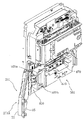
前記第1制御基板ユニット201は、第1制御基板ボックス201A、後述の開閉機構
410および連結取付台座部材430を含み、第1制御基板ボックス201Aは、第1制
御基板ユニット201の主要部をなす部材であり、図8乃至図15に示すように、外側ケ
ース70および内側ケース85を含む。この実施例では、外側ケース70が主制御装置2
61の制御基板80を収容する容積のある方であり、内側ケース85がその蓋体に相当す
る方である。上記外側ケース70および内側ケース85は第1ケースおよび第2ケースに
相当するものであるが、外側ケース70および内側ケース85のうちいずれを第1ケース
としいずれを第2ケースとするかは任意である。
この第1制御基板ボックス201Aは、前記外側ケース70側に設けられる外側封印部
71と、前記内側ケース85側に設けられる内側封印部86と、その外側封印部71と内
側封印部86とを連結する封印部材87とを有し、その封印部材87によって前記外側封
印部71と内側封印部86とが連結されている場合に前記制御基板80を取り出すときに
は第1制御基板ボックス201Aを破壊するか或いは所定の部位を切断することを必要と
するものである。
The first
61 has a capacity to accommodate the control board 80, and the
The first
前記外側ケース70の外側封印部71と内側ケース85の内側封印部86とは対を成す
もので、この実施例では、個別に使用することのできる4個の封印部(封印、開封の再使
用不可)から構成されており、それぞれを、封印部材87を用いて封印するよう構成され
たものであり、こうした封印構造は、公知に属するものと変わらないものであるから、こ
こでの詳細説明は省略する。
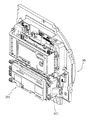
The
図8は、遊技球が流下する遊技領域を前面側に形成してある遊技盤30の裏面の斜視図
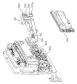
である。図9は、第1制御基板ボックス201Aを開閉機構410から取り外した状態を
示す。
FIG. 8 is a perspective view of the back surface of the
上記開閉機構410は、第3部材としての回動連結のための軸411を備え、一端側、
即ち、コの字形に折り曲げられた一枚の支持板(約2mm厚の鋼板)からなる第1部材と
しての支持体412が、図15に示すようにそのコの字の底板部分で遊技盤30の裏面側
にネジで固定され、他端側は、その軸411を基点にして回動するように枢着された第2
部材としてのブラケット413で構成されている。前記軸411は、リベット構造であり
、その両端部を変形させることよって容易に抜き取り出来ないようにされている。
The opening /
That is, the
It is comprised with the
前記第1部材としての支持体412のコの字の底板部分にはネジ孔が設けられ、図15
に示すように、遊技盤30の裏面と球集合板460(入賞装置に入球した遊技球を受けて
下方へ誘導する排出通路が形成されているもの)との間でネジ固定され、球集合板460
の開口部461(又は切り欠き部)を介して遊技機の裏面側に向かう方向に突出する。そ
して、このブラケット413は、板状体で構成されて第1係合部414(後述の連結取付
台座部材430に対する)に構成され、その第1係合部414には、図16に示す切り欠
き係合部415が形成されている。この切り欠き係合部415は、切り欠き部分の両側の
先端部が互いに対向する方向に鉤状に突出し、全体として概略C字形状となるように形成
されている。
A screw hole is provided in the U-shaped bottom plate portion of the
As shown in FIG. 4, the ball assembly is fixed with screws between the back surface of the
Projecting in the direction toward the back side of the gaming machine through the opening 461 (or notch). And this
上記構造とすることにより、球集合板460を遊技盤30に取り付けた後は支持体41
2が外側から取り外せない状態となるので、例えば後述する第1制御基板ボックス201
Aを不正に取り外したりすることがより困難となる。
With the above structure, after the
2 is in a state that cannot be removed from the outside, for example, a first
It becomes more difficult to remove A illegally.
上記球集合板460については、その外周部の複数個所を遊技盤30の裏面に対して固
定するが、そのうちの少なくとも一つが固定解除できないように、後述する破断ネジ等で
するか、ビス留めしたあと、ビス頭部を覆うキャップを取り付けるようにする等して、球
集合板460が遊技盤30から容易に外されるのを防止する構造としてもよい。
The
上記切り欠き係合部415は、後述の第2係合部433とでもって、第1係合部414
の抜け出し防止の規制機構440を構成する。前記ブラケット413(約2mm厚の鋼板
)には、図16に示すように、前記支持体412に枢支連結される一枚の支持板からなる
支持部413Aが形成されており、その支持部413Aは、ブラケット本体部から直角に
折り曲げられて側面視で門型に形成されている。
The
A restricting mechanism 440 for preventing the slipping out is formed. As shown in FIG. 16, the bracket 413 (steel plate having a thickness of about 2 mm) is formed with a support portion 413A composed of a single support plate that is pivotally connected to the
尚、前記第1制御基板ボックス201Aは、既述の通り、外側封印部71を備える外側
ケース70と内側封印部86を備える内側ケース85を有し、主に外側ケース70の内部
に遊技を制御する制御基板を収容する構成のものである。
As described above, the first
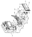
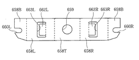
次に、図9乃至図18に基づいて、連結取付台座部材430について述べる。
この連結取付台座部材430は、前記開閉機構410と前記第1制御基板ボックス20
1Aとにそれぞれ連結されるものであり、言わば従来から用いられていた基板ボックスを
取り付けるための取付台座に相当するものであって、合成樹脂で成型されており、ここで
は、幅は、前記第1制御基板ボックス201Aの幅と実質的に同じ幅(約150mm)で
、長さが約48mm(第1制御基板ボックス201Aの長手方向に向かう長さ)、厚みが
13mm、肉厚は、2mmのものであり、第1制御基板ボックス201Aの内側ケース8
5の側面に接当する側が開放され、リブが多数設けられ、破断ネジ439を収容する収容
部431が、ここでは3個形成されており、そこに破断ネジ439がそれぞれ1本づつセ
ットされるようになっているが、周壁、リブの端面は同じレベルに形成され、内側ケース
85の側面に密着接当可能にされており、反対側の側面(遊技盤30側)は、平坦に形成
されている。
Next, the connection mounting
The connection mounting
1A, which corresponds to a mounting base for mounting a conventionally used board box, and is molded of synthetic resin, where the width is 1 The width of the
The side that contacts the side surface of 5 is opened, a large number of ribs are provided, and three receiving
前記第1制御基板ボックス201Aのうち、前記連結取付台座部材430と連結封止さ
れる部位である第1取付台座封止部450が、その内側ケース85の端部に設けられてお
り、ここでは該第1制御基板ボックス201Aの幅方向に、所定の間隔を隔てて4個突設
されている。この第1取付台座封止部450は、外側ケース70の外側封印部71と内側
ケース85の内側封印部86との位置と平面視で位相がずれるように変位して配置されて
おり
、従って、第1制御基板ボックス201Aを背面から(遊技機の背面から)見たときに、
前記外側封印部71と内側封印部86に重なることなく、視認できる状態にある。 即ち
、前記外側封印部71と内側封印部86の位置する側に前記第1取付台座封止部450が
配置され、且つ、前記第1制御基板ボックス201Aの背面視(正面)において、前記第
1取付台座封止部450が見えるように前記外側および内側封印部71、86と平面位相
をずらせて配置されているのである。
Of the first
The
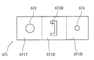
そして、前記連結取付台座部材430には、前記第1制御基板ボックス201Aの前記
第1取付台座封止部450と連結封止される部位である第2取付台座封止部432が、こ
こでは、4個が、前記4個の第1取付台座封止部450と対応する位置に突設されている
。この1個の第2取付台座封止部432の構造は、この連結取付台座部材430の本体に
繋がるリブに、有底のネジ止め凹部を有する突起体が一体成型されており、そのリブの底
面と有底板分の底面は面一で、且つ、前記収容部431のリブ及び周壁のレベルと面一と
されている。
そして、前記第1、及び第2取付台座封止部450、432は、破断ネジを用いて連結
封止される。
The connection mounting
And the said 1st and 2nd mounting
前記連結取付台座部材430の内部に、前記開閉機構410の前記第1係合部414と
係合する部位である第2係合部433が設けられる。この第2係合部433は、この実施
例では、後述する第1被覆部材430Aとは別体成型の第2被覆部材430Bに取り付け
られる。勿論、別体の第2被覆部材430Bが存在せず、第2係合部433が連結取付台
座部材430の樹脂成型時に埋め込まれたり、或いは、それ自体の弾性変形を利用して、
連結取付台座部材430に形成された挿入部434の内部に挿入設置されるように構成さ
れてもよいものである。
A second engagement portion 433 that is a portion that engages with the
It may be configured to be inserted and installed in the
前記第2係合部433は、ここでは、弾性を備えた一枚の薄い板体(鋼板)を折曲成形
して構成されている。即ち、概略縦長の長方形の板体の一方長辺に沿って延びる帯状部を
直角に折曲し、さらにこの帯状部の両端部を内側方向(板体の他方長辺側方向)へ90度
未満の小角度(例えば20〜60度程度)だけ折曲して弾性係合爪を形成した構成となっ
ている。一方、前記第1係合部414は、金属製の平板状体で構成され、そこに切り欠き
係合部415が形成され、該切り欠き係合突片部415に前記第2係合部433の係合爪
を係合させることによって、抜け出し防止の規制機構440Dが構成されている。そして
、前記開閉機構410の前記第1係合部414を挿入して前記連結台座部材430の内部
の前記第2係合部433に係合させるために前記連結台座部材430に、挿入部434が
形成されている。
Here, the second engaging portion 433 is formed by bending a thin plate (steel plate) having elasticity. That is, a belt-like portion extending along one long side of a substantially vertically long rectangular plate is bent at a right angle, and both ends of the belt-like portion are directed inward (to the other long side of the plate) at less than 90 degrees. It is the structure which bent only the small angle (for example, about 20-60 degrees), and formed the elastic engagement nail | claw. On the other hand, the
このように、前記規制機構440Dは、前記第1係合部414と前記第2係合部433
との係合において、前記開閉機構410の第1係合部414が前記挿入部434に挿入さ
れて前記第2係合部433と係合されたあとにその挿入方向とは逆の抜き出す方向への移
動を規制するものである。
As described above, the restriction mechanism 440D includes the
When the
なお図10には、図示を明確化するため、第1係合部414を前記挿入部434に挿入
した状態で、第2部材すなわちブラケット413ごと第1制御基板ボックス201Aが球
集合板460から分離した状態が示されているが、実際のパチンコ機10においては、ブ
ラケット413は第1制御基板ボックス201A側(連結取付台座部材430)よりも先
に、球集合板460側(第1部材すなわち支持体412)に取り付けられた構造となって
いる。
In FIG. 10, for clarity of illustration, the first
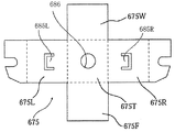
ここで、更に、前記連結取付台座部材430について詳述する。前記第2係合部433
を被覆するべく前記連結取付台座部材430には、第1被覆部材430Aと第2被覆部材
430Bが備えられている。第1被覆部材430Aが前記連結取付台座部材430に一体
形成されたもので、第2被覆部材430Bは、前記連結取付台座部材430に組み合わせ
るよう別体構成とされ、且つ、その少なくとも一方、ここでは第1被覆部材430Aに凹
面が形成され、他方、即ち、第2被覆部材430Bに対向するよう組み合わせることで前
記第1係合部を挿入するための前記挿入部434を形成している。具体的には、前記挿入
部434は、その入口が、入口側から内部に向かって幅狭となるようにテーパ状に形成さ
れ、且つ、挿入方向に沿って複数、ここでは4本の案内リブが形成されている。
Here, the connection mounting
The connection mounting
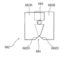
そして、この第2被覆部材430Bに、前記第2係合部433が設けられるが、その第
2係合部433の薄板を、第2被覆部材430Bに形成した係止突片430Cに、その入
口の側からスライド挿入して係止させ、且つ、ネジ止めされる。
前記第2被覆部材430Bは、前記第1被覆部材430Aよりも小さく構成され、前記
連結取付台座部材430と前記第1制御基板ボックス201Aとが連結した状態において
は、前記第2被覆部材430Bの取り外し方向側に前記第1制御基板ボックス201Aが
位置された状態となり、前記第1制御基板ボックス201Aと前記第1被覆部材430A
とにより被覆された状態となるように構成されているものである。
The
The
It is comprised so that it may be in the state coat | covered by.
また、前記連結取付台座部材430は、前記第1制御基板ボックス201Aよりも小さ
く構成され、前記第1制御基板ボックス201Aのうち、基板裏面側で一端側に寄せて連
結されるように構成されているものである。
Further, the connection mounting
更に、上述した通り、前記第1及び第2被覆部材430A、430Bを透明樹脂により
成型し、これらに被覆される第2係合部433を金属製の係合部材により構成してある。
前記第1制御基板ボックス201Aの側面に、係止リブ420、420、420が前記
連結取付台座部材430の略周部に沿って配置されて突出するように備えられ、該係止リ
ブ420、420、420に所定の方向、即ち、第1制御基板ボックス201Aの裏面に
沿って第1、第2取付台座封止部や第1連結部の位置する側から第1制御基板ボックス2
01Aの中央側に向けてスライド移動させることによって、係合するリブ係合部435が
前記連結取付台座部材430の側部に設けられると共にその一つの係止リブ420が、前
記連結取付台座部材430の収容部431の周壁の内側に形成されたリブ係合部436に
係合するように設けられている。
Further, as described above, the first and
Locking ribs 420, 420, 420 are provided on the side surface of the first
By sliding and moving toward the center side of 01A, a rib engaging portion 435 to be engaged is provided on the side portion of the connection mounting
前述の別体構成の前記第2被覆部材430Bの両側部にカム面を備えた係合片430D
、430Dが突設され、前記連結取付台座部材430の内部に前記係合片430D、43
0Dに係合する門型の係合部430E、430Eがそれぞれ設けられ、前記第2被覆部材
430Bを前記連結取付台座部材430に対して押し付けることで前記カム面作用により
前記係合部430D、430Dの素材の弾性変形を利用して門型の係合部430E、43
0Eへの係合が行われるように構成されている。
430D project, and the
Gate-
It is configured to engage with 0E.
本実施形態のパチンコ機10においては、遊技機に取り付けられた第1制御基板ユニッ
ト201が遊技盤30の裏面に対して開閉することにより、遊技盤裏面の設置物に対して
の検査、メンテナンスが容易に行い得るのである。
そして、封印部により封印されることにより、制御基板に対して不正な改変を行ったり
、不正品に交換されることを防止でき、また、第1、第2取付台座封止部450、432
により連結封止することによって、第1制御基板ユニット201を不正品に交換されるこ
とを防止できる。
In the
Further, by sealing with the sealing part, it is possible to prevent the control board from being illegally altered or exchanged with an illegal product, and the first and second mounting
By connecting and sealing with the above, it is possible to prevent the first
更に、連結取付台座部材430に対して開閉機構410を簡単な操作により装着できる
ので、作業性が向上するのであり、そして、第1係合部414と第2係合部433とを一
度係合させるとその解除が規制機構440Dによって規制され、係合部分は被覆されてい
るので、連結状態の第1制御基板ボックス201Aおよび開閉機構410、即ち第1制御
基板ユニット201ごと不正に持ち去ることを防止できるのである。
Further, since the opening /
次に、第1被覆部材430Aが前記連結取付台座部材430に一体形成されるのに対し
、第2被覆部材430Bが前記連結取付台座部材430に組み合わせるよう別体構成とさ
れることで、第2係合部433を被覆することを行い得ながら、第2係合部433を第2
被覆部材430Bに備えておいて、これを後に組み合わせるという作業で、この、第2係
合部433を前記連結取付台座部材430の内部に備えることができる。
Next, the
The second engaging portion 433 can be provided inside the connection mounting
また、前記連結取付台座部材430と前記第1制御基板ボックス201Aとが連結した
状態においては、第2被覆部材430Bが前記第1制御基板ボックス201Aの側に位置
して、前記第1被覆部材430Aとで挟まれた状態となって第2係合部433の被覆が行
われ、その被覆が容易に外れない。
Further, in a state where the connection mounting
更に、連結取付台座部材430は、前記第1制御基板ボックス201Aよりも小さく構
成され、前記第1制御基板ボックス201Aのうち、基板裏面側で一端側に寄せて連結さ
れる構成であるので、従来のような基板ボックスと同等の大型の取付台座を必要とするこ
とがない状態で、その第1制御基板ボックス201Aの開閉を行い得るのである。
Further, the connection mounting
更に、前記第1及び第2被覆部材430A、430Bを透明樹脂により成型し、これら
に被覆される第2係合部433を金属製の係合部材により構成してあることで、第1係合
部414と第2係合部433の係合状態が確実におこなわれているかどうか外部から視認
でき、また、強固な係合がされていることが視認されることで、安易な取り外しが行われ
ないようにすることができる。
Further, the first and
また、前記第2係合部433を板金で構成してその一部を変形させることで第1係合部
414に対する係合を行う構成であるので、極めて構造が簡単であり、同時に、係合状態
の解除が容易に行われないものである。
Further, since the second engaging portion 433 is made of a sheet metal and part of the second engaging portion 433 is deformed to engage with the first engaging
更に、挿入部434の入口をテーパ状として、且つ、案内リブを設けることで、第1係
合部414の挿入を容易にすることができると共に内部への侵入がガイドされてスムース
に行い得るのである。
Furthermore, the insertion of the first engaging
また、外側ケース70の前記外側封印部71と内側ケース85の内側封印部86の位置
する側に前記第1取付台座封止部450及び第2取付台座封止部432が配置されるもの
の、前記第1、及び第2取付台座封止部450、432が見えるように前記外側および内
側封印部と平面位相をずらせて配置されていることで、前記第1、及び第2取付台座封止
部450、432が前記第1制御基板ボックス201Aの背面視(正面)において、視認
可能となり、前記第1、及び第2取付台座封止部450、432が不正に解除されている
かどうか容易に分かるのである。
Although the first mounting
また、第1制御基板ボックス201Aの側面に、係止リブ420を突出するように設け
、前記連結取付台座部材430を係止させて位置決めすることができ、その後の前記第1
取付台座封止部450及び第2取付台座封止部432の連結が行い易いのである。
Further, a locking rib 420 is provided on the side surface of the first
The attachment
更に、前記第2被覆部材430Bを連結取付台座部材430に取り付けるに、第2被覆
部材430Bのカム面を備えた係合片430Dと、連結取付台座部材430の前記係合片
430Dに係合する係合部430Eの存在によって、第2被覆部材430Bを連結取付台
座部材430に向けて押圧するだけで、素材の弾性変形でもって係合が行われることにな
り、簡単に組み付けができる。
Further, to attach the
また、連結取付台座部材430に、破断ネジ439を収容する収容部431を設けるこ
とで、第1制御基板ボックス201Aの定期検査等で封止を解いた後に、そこから破断ネ
ジ439をとり出して、再び新たな第1取付台座封止部450と第2取付台座封止部43
2との封止を行うことができる。
Further, by providing the connecting mounting
2 can be sealed.
(開閉機構の一部変形例)
上記開閉機構410の他端側である第2部材、第1、第2取付台座封止部450,43
2を、破断ネジで連結させてもよい。
(Partial modification of the opening / closing mechanism)
The second member on the other end side of the opening /
2 may be connected by a break screw.
また、第1取付台座封止部450に形成された切断部450A(図9他参照)を切断し
て、破断ネジは第2取付台座封止部及び第2部材に残すようにすれば連結封止を解除でき
る。 更に、別の変形例として、第1、第2連結部の両方に切断部を形成し、破断ネジを
第2部材に残すようにしてもよい。
Further, if the cutting
また、この例では、第1係合部414を構成する金属製の平板状体を方形状に打ち抜い
て開口係合部417が形成されており、該開口係合部417に前記第2係合部433の舌
片433dの係合爪を係合させることによって、抜け出し防止の規制機構440Dが構成
されている。
Further, in this example, an opening engaging portion 417 is formed by punching a metal flat plate constituting the first engaging
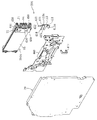
遊技盤30の裏面と第1制御基板ユニット201との間には、カバー部材501が介装
されている。図14及び図15に示すように、遊技盤30の裏面には球集合板460が設
けられ、第1制御基板ユニット201はこの球集合板460に外側から取り付けられる構
成となっているが、該球集合板460と第1制御基板ユニット201との間には、若干の
間隙が形成されている。パチンコ機10の機種によっては、遊技盤30の裏面の設計に応
じて、当該部位の寸法(奥行)が異なる。このため、この寸法の変動に対応できるように
、球集合板460と第1制御基板ユニット201との間には、若干の余裕、すなわち間隙
が形成されているのである。前記カバー部材501は、この球集合板460と第1制御基
板ユニット201との間の間隙を補填するためのものであり、当該間隙にほぼ対応した寸
法を有するものとなっている。
A
上記カバー部材501を設けた主たる目的は、球集合板460の裏面に設けられた種々
の電気部品、例えば、遊技盤30の表面に設けられた電飾用の基板等の電気部品、配線な
どを保護することになる。即ち、この球集合板460の裏面に露出された状態に配置され
ているものであるから、裏面側からアタック(多の部品の組み付け時、或いは基板ボック
スの開閉時)に際して、破損、破断が生じる虞がある。
The main purpose of providing the
この他に、球集合板460の裏面中央には、中継基板470、これにつながるコネクタ
、配線が設けられている。ここでは、中継基板470は、表裏2段配置に構成されており
、裏面側(外側)では、第1制御基板ユニット201からの入力を、大入賞口作動のため
の中継とし、また一部の電飾に中継し、また、入球を検知するセンサーの出力を中継して
いる。同様に、内側の中継基板については、電飾等の中継を行う。
また、球集合板460の裏面に露出されている基板としては、大当たりに際して開く大
入賞口装置471(図5参照)のための制御(ソレノイド、センサー)を行う中継基板4
73がある。これらの中継基板470、中継基板473については、この実施例では、前
記カバー部材501の被覆対象外となっている。即ち、これらの中継基板470、中継基
板473を覆いから外すように、即ち、その中継基板470に対しては、このカバー部材
501の一部を凹ませた形状とし、その中継基板473については、中抜き形状(窓)と
して、そのカバー部材501の形状が採られている。
In addition, a
Further, as the substrate exposed on the back surface of the
There are 73. The
上記カバー部材501は、球集合板460に対向する面が開放された概略横長で中空体
(箱形)に形成され、その上端部にはほぼ矩形状の切欠部511が形成されている。この
切欠部511は、球集合板460と第1制御基板ユニット201とを電気的に接続するス
ペースを確保するためのものである。
The
上記カバー部材501の内部には、図14に示すように、複数のリブ512が形成され
ている。このリブ512は、カバー部材501の補強の機能だけでなく、該カバー部材5
01の内部に不正基板を設置し得るスペースが形成されないようにするという機能も奏す
るものである。また、このリブ512は、球集合板460側に設けた電気部品等に接当し
ないように区画配置されると共にその高さが部分的に変えられている(リブの外縁面が同
じレベルではない)。
A plurality of
This also has a function of preventing a space in which an unauthorized substrate can be installed from being formed in 01. In addition, the
上記カバー部材501は透明樹脂よりなるものであり、これにより、内部での不正行為
の有無等が外側から容易に視認することができ、したがって不正をより効果的に防止し得
るようになっている。
The
上記カバー部材501の一方端部には、上下1対の板状のブラケット513が突設され
ている。該ブラケット513の先端部には孔または切欠が形成されており、一方、前記球
集合板460における前記開閉機構410形成側端部とは反対側の端部(図14および図
15では右側端部)には、上下1対の軸462がそれぞれ上方に突出するように設けられ
ており、この軸462に前記カバー部材501のブラケット513が挿通されている。こ
れにより、上記カバー部材501は一方端部で軸462を中心として水平面上で回動可能
に軸支され開閉可能となっている。即ち、該カバー部材501の開閉軸線はパチンコ機1
0の背面からみて前記開閉機構410形成側端部の反対側(図14および図15の右側)
で上下に延びるように設定されており、この開閉軸線を軸心にしてカバー部材501が後
方側に十分に開放できるようになっている。
A pair of upper and lower plate-shaped
The side opposite to the end of the opening and
The
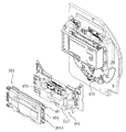
前記第1制御基板ボックス201Aは、図13に示すように開閉機構410により該開
閉機構410形成側端部(図13では左側端部)で回動させて一方側へ(図13では左方
に)開放し得るようになっているが、上記のようなカバー部材501の支持構造とするこ
とにより、該カバー部材501は図14に示すように第1制御基板ボックス201Aとは
逆方向に(図14では右方に)開放し得るようになっている。すなわち、該カバー部材5
01と第1制御基板ボックス201Aとが、左右逆方向に開閉し得る構造、さらに具体的
にいえば、左右から折り重ねるようにして閉じ得るとともに、その閉じた状態からそれぞ
れ左右に開放し得る構造となっている。
As shown in FIG. 13, the first
01 and the first
上記カバー部材501の自由端部側(図9及び図11では左端部側)およびこれに対応
する球集合板460上の位置には、カバー部材501と球集合板460とを封止するため
の封止手段が設けられている。この封止手段は、第1封止部520Aと第2封止部520
Bとを有している。この第1封止部520Aおよび第2封止部520Bについて以下順次
説明する。
The
B. The first sealing portion 520A and the second sealing portion 520B will be sequentially described below.
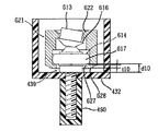
図19に示すように、第1封止部520Aは、球集合板460に遊技盤30側から挿通
されてカバー部材501を球集合板460に固定する固定手段であるネジ519と、球集
合板460の遊技盤30側に設けられネジ519が挿通される孔を底板に有する凹部46
5と、カバー部材501に設けられネジ519が挿入され固定される挿入部514と、ネ
ジ519による固定状態を解除するために挿入部514に設けられた切断部514Aとか
ら構成されている。
As shown in FIG. 19, the first sealing portion 520A includes a
5, an
カバー部材501の自由端において球集合板460に当接する上下2箇所のコーナー部
からは、それぞれ、上下1組の方形状の延出片が、互いに平行となるように、水平に平伏
した状態で、カバー部材501の長さ方向に沿って延出し、上下1組の延出片のうち内側
に位置する延出片の先端部が外方に屈曲して外側の延出片に向かって延び、これら上下の
延出片の先端部分が、カバー部材501の奥行方向に沿って延びる円筒状部を支持するよ
うな形状となるように、カバー部材501のコーナー部が成形されている。上記円筒状部
の内部にはネジ溝が形成されてネジ519が螺入し得るようになっており、この円筒状部
が挿入部514となっている。また、上記上下1組の方形状の延出片は、ネジ519によ
る固定状態を保持するのに十分な強度を有するとともに、ニッパ等の適宜手段により容易
に切断し得る肉厚を有するものとなっており、この延出片が切断部514Aとなっている
。
From the two upper and lower corner portions that contact the
一方、球集合板460において上記カバー部材501の上下のコーナー部に対応する位
置にはそれぞれ、凹部465が設けられている。下側の凹部465は、球集合板460の
取付面(遊技盤30側面)から円形の平面形状をなして陥入し、その底板にはネジ挿通孔
が穿設された構成となっている。上側の凹部465は、球集合板460の取付面(遊技盤
30側面)から、下側の一隅を部分円状に角落ちさせた概略方形状の平面形状をなして陥
入し、その底板にはネジ挿通孔が穿設された構成となっている。上下の凹部465のネジ
挿通孔にはそれぞれ、遊技盤30側からネジ519が挿通され、該ネジ519の頭部が凹
部465内に収容されるとともに、軸部が前記カバー部材501の挿入部514に螺合し
、これによりカバー部材501の自由端部が球集合板460に固定されるようになってい
る。
On the other hand,
球集合板460が遊技盤30に取り付けられた状態では、球集合板460の凹部465
がネジ519のネジ頭を収容して遊技盤30により閉塞された状態、すなわちネジ519
のネジ頭が球集合板460と遊技盤30との間に挟まれた状態となるため、外部からネジ
519を取り外すことが不可能であり、これにより、カバー部材501と球集合板460
とが封止されるようになっている。一方、たとえば球集合板460の裏側の点検などを目
的としてカバー部材501を開放する場合には、前記切断部514Aを切断することによ
り、カバー部材501と球集合板460との封止状態を外側から(パチンコ機10の背面
側から)、痕跡を残しながら解除することができる。
In a state where the
In the state where the screw head of the
Since the screw head of the ball is sandwiched between the
Are sealed. On the other hand, for example, when the
なお、固定手段として、ネジにかえてナイラッチ等を用いるようにしてもよい。ナイラ
ッチは、頭部から延出する軸部の先端部が径方向に拡張するように成形されたナイロン製
の締結具であり、締結対象の部材に設けた孔部に押し込んで弾性的に係合させることによ
り当該部材を締結するものである。
Note that a ny latch or the like may be used instead of the screw as the fixing means. Nylon is a nylon fastener molded so that the tip of the shaft extending from the head expands in the radial direction, and is elastically engaged by being pushed into the hole provided in the member to be fastened. By doing so, the member is fastened.
第2封止部520Bは、カバー部材501に背面側から挿通されてカバー部材501を
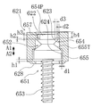
球集合板460に固定する破断ネジ522と、カバー部材501に設けられ破断ネジ52
2が挿通される孔を底板に有する破断ネジ挿通部515、516と、球集合板460に設
けられ破断ネジ522が螺入される螺入部463、464と、破断ネジ522による固定
状態を解除するために破断ネジ挿通部515、516に設けられた切断部515A、51
6Aとから構成されている。上記破断ネジ522は、第1取付台座封止部450と第2取
付台座封止部432とを連結封止するための、後述する破断ネジ439と同様の構成を有
するものとなっており、ここでは説明を省略する。
The
2, rupture
6A. The breaking
カバー部材501の自由端は、高さ方向における中段をなす帯域部分が内側に陥入して
、正面視概略コ字状の形状を有しており、その陥入部分の底板から、高さ方向に長く延び
る概略直方体状の基台部515Bが外側(カバー部材501の自由端側)に突出し、さら
に該基台部515Bの外側端面から、破断ネジ挿通部515が外側に突出した形状となっ
ている。基台部515Bの外側端面の上端部および下端部からは、それぞれ、上下1組の
方形状の延出片が、互いに平行となるように、水平に平伏した状態で、カバー部材501
の長さ方向に沿って延出し、上下の延出片の先端部同士がたがいに近接し合う方向に円弧
状に湾曲するように延びて接合し、正面視半円状の周壁部515Cが形成されている。こ
の周壁部515Cを含む上下の延出片は全体として正面視U字状に形成され、その先端部
分の内側における奥行方向中央付近には、奥行方向に対し垂直となるように、即ち、例え
ば遊技盤30の裏面に対し平行となるように、底壁515Dが設けられ、該底壁515D
にはネジ挿通孔(図示せず)が穿設されている。
The free end of the
The end portions of the upper and lower extension pieces extend in a circular arc shape and are joined together so as to form a semicircular
A screw insertion hole (not shown) is formed in the.
上記周壁部515Cを含む上下の延出片および底壁515Dにより、破断ネジ挿通部5
15が構成されている。上記上下の延出片は、前記第1封止部520Aの切断部514A
と同様に、十分な強度を有するとともに容易に切断し得る肉厚を有するものとなっており
、また、前記底壁515Dは上下の延出片の先端部の間の空間のみを閉塞しこれより内側
の脚部(立ち上がり部)の間の空間は閉塞しないように設けられていて、この脚部は奥行
方向に貫通する形状となっている。このように構成されることにより、上記上下の延出片
の脚部が第2封止部520Bの切断部515Aとなっている。
The broken screw insertion portion 5 is formed by the upper and lower extending pieces including the
15 is configured. The upper and lower extending pieces are cut
Similarly, the
一方、図15に示すように、球集合板460において上記上下の破断ネジ挿通部515
に対応する位置にはそれぞれ、螺入部463が設けられている。上下の螺入部463は、
球集合板460における前記支持体412挿通用の上下の開口部461の間の位置から、
背面側(カバー部材501側)へ延出する円筒状に形成され、その内部にはネジ溝が設け
られて破断ネジ522が螺入され得るようになっている。
On the other hand, as shown in FIG. 15, the upper and lower broken
A screw-in
From the position between the upper and
It is formed in a cylindrical shape extending to the back side (the
図19に示すように、カバー部材501を閉じて球集合板460に当接させた状態では
、破断ネジ挿通部515の周壁部515Cの球集合板460側端縁も球集合板460に当
接し、螺入部463の全体が該周壁部515Cにより包囲されるようになっている。この
状態で、破断ネジ522が破断ネジ挿通部515に背面側(カバー部材501側)から挿
通されて螺入部463に螺入され、これによりカバー部材501が球集合板460に固定
される。破断ネジ522は、後述するように所定の高トルクで回転させることにより頭部
の先端側の分離部が破断して分離する。この状態では、ドライバによって破断ネジ522
を回転させることはできず、しかも破断ネジ522は破断ネジ挿通部515の周壁部51
5Cで包囲されているため、痕跡を残さずに破断ネジ522を取り除くことは不可能であ
る。これにより、カバー部材501と球集合板460とが封止された状態となる。一方、
前記切断部515Aを切断することにより、カバー部材501と球集合板460との封止
状態を痕跡を残しながら解除することができる。
As shown in FIG. 19, when the
, And the breaking
Since it is surrounded by 5C, it is impossible to remove the breaking
By cutting the cutting
カバー部材501の自由端は、前記したように中段をなす帯域部分が内側に陥入した正
面視概略コ字状の形状を有しているが、その陥入部分を挟む上段および下段の突出部分の
先端面には、それぞれ前記第1封止部520Aが設けられている。さらに、下段の突出部
分の先端面において、第1封止部520Aの上方の位置に、破断ネジ挿通部516が設け
られている。この破断ネジ挿通部516は、前記陥入部分の底板に設けられた破断ネジ挿
通部515とほぼ同様の上下の延出片(周壁部を含む)および底壁を有する構成となって
いる。
As described above, the free end of the
また、図15に示すように、球集合板460において上記カバー部材501の下段の突
出部分に設けられた破断ネジ挿通部516に対応する位置には螺入部464が設けられて
おり、この螺入部464は前記螺入部463と同様に、背面側(カバー部材501側)へ
延出する円筒状に形成され、その内部にはネジ溝が設けられて破断ネジ522が螺入され
得るようになっている。本実施形態に示す第2封止部520Bは、カバー部材501の陥
入部分の底板に設けられた上下の破断ネジ挿通部515および突出部分に設けられた破断
ネジ挿通部516と、これら破断ネジ挿通部515、516にそれぞれ対応するように球
集合板460に設けられた螺入部463、464と、破断ネジ挿通部515、516のそ
れぞれに設けられた切断部515A、516Aと、破断ネジ522とで構成され、高さ方
向に並ぶ3点でカバー部材501と球集合板460との封止がなされ得るようになってい
る。
Further, as shown in FIG. 15, a screw-in
上記カバー部材501の陥入部分の底板に設けられた上下の破断ネジ挿通部515は、
図9および図11に示すように、前記開閉機構410におけるブラケット413の上下の
支持部413Aの間に挟持されるような位置に形成され、これら支持部413Aの間のス
ペースをほぼ閉塞し、第1制御基板ボックス201Aを枢着する軸411であるリベット
の頭部に近接している。
The upper and lower breaking
As shown in FIGS. 9 and 11, the opening /
図9乃至図11ならびに図21に示すように、上記カバー部材501の外側面(第1制
御基板ボックス201A側面)における固定端部(図9、図11及び図21では右側端部
)には、先端に係止爪が形成された矩形状の係止片517が後方に(第1制御基板ボック
ス201A側に)突出するように配設され、一方、第1制御基板ボックス201Aの内側
ケース85の自由端部には、矩形状の突起部851が側方に(図21では右方に)突出す
るように配設されており、図22に示すように該係止片517が突起部851に弾性的に
係止し得るようになっている。この係止片517は、カバー部材501に一体成型されて
いる。
As shown in FIG. 9 to FIG. 11 and FIG. 21, the fixed end portion (the right end portion in FIG. 9, FIG. 11 and FIG. 21) on the outer surface (side surface of the first
また、上記カバー部材501の外側面における自由端部には、図11に示すように、矩
形状凹部518が形成されている。この矩形状凹部518は、前記連結取付台座部材43
0の長さ(約48mm)および厚み(約13mm)にそれぞれほぼ等しい長さ(カバー部
材501の長手方向に沿った長さ)および深さを有し、図9に示すように、内部に連結取
付台座部材430をほぼ隙間なく収容することができ、収容状態で該連結取付台座部材4
30の外側面(開放側面)とカバー部材501の外側面とが面一となるようになっている
。これにより、第1制御基板ボックス201Aとの間にできる限り間隙が形成されないよ
うになっている。
Further, as shown in FIG. 11, a
9 has a length (length along the longitudinal direction of the cover member 501) and a depth substantially equal to a length (about 48 mm) and a thickness (about 13 mm), and is connected to the inside as shown in FIG. The mounting
The outer side surface (open side surface) of 30 and the outer side surface of the
(カバー部材の一部変形例)
図23に示すように、上記カバー部材501の内部に形成するリブの数を少なくするよ
うにしてもよい。図23に示す例では、リブの形成が前記実施例の場合よりも大幅に少な
く、これに応じて区画された室数も少なくなっている。さらには、カバー部材501の内
部にリブを形成せず、内部空間を区画しないようにしてもよく、あるいは、カバー部材の
内部に適宜な材料を充填して内部空間を実質的になくすようにしてもよい。
(Partial modification of cover member)
As shown in FIG. 23, the number of ribs formed inside the
また、上記図23に示す例では、カバー部材501内の壁面に、第2封止部520B用
の破断ネジ522を収容する破断ネジ収容部521が、ここでは3個形成されており、そ
こに破断ネジ522がそれぞれ1本づつセットされるようになっている。これにより、カ
バー部材501の封止を解除して開放するごとに、破断ネジを1本ずつ取り出し第2封止
部520Bの3箇所の破断ネジ挿通部515、516に挿通・螺合して次の封止を行うよ
うにすることができ、未使用の破断ネジ522は封止した状態のカバー部材501の内部
に確実に保持しておくことができる。この破断ネジ収容部521は、例えば、1本の破断
ネジのみを収容する構成としてもよく、この場合にも、破断ネジを未使用の段階ではカバ
ー部材の内部に保持しておくことができる。
Further, in the example shown in FIG. 23, three breaking
また、上記パチンコ機10においては、カバー部材501の一方端部およびこれに対応
する球集合板460の位置に、第1および第2封止部520A、520Bで構成される封
止手段を設けた構造としていたが、これと同様のまたは異なる封止手段を他方端部にも設
け、これにより、カバー部材501の両端部を封止した状態で固定する構造とするように
してもよい。この場合、前記カバー部材501の開閉構造(回動可能に軸支した構造)を
設けた端部にさらに封止手段を設けるようにしてもよいが、両端部が封止手段により固定
されるため、開閉構造は省略することができる。
Further, in the
上記パチンコ機10においては、遊技盤30の裏面の球集合板460の裏面を覆うよう
にカバー部材501が設けられていることにより、球集合板460の裏面に配置された中
継基板、配線等の電気部品を保護することができ、他の電気部品の組み付け、或いは外部
からの他物の接触による電気部品の破損、断線が防止できるのである。 即ち、パチンコ
機10の組立てにおいては、例えば、球集合板460に中継基板、LED基板、スイッチ
、配線等の電気部品を取り付け、この球集合板460にカバー部材501を取り付けてこ
れらをユニットとして構成し、このユニットを遊技盤30に取り付け、この後第1制御基
板ユニット201を取り付けるという工程にすると、作業性が良好となるが、このような
場合に、電気部品も少なくとも一部がカバー部材501で覆われるようにすることで、電
気部品がカバー部材501によって保護され、取り付け作業時に電気部品が破損されるこ
とが防止される。
In the
又、遊技盤30の裏面と第1制御基板ユニット201との間の間隙が補填され、これに
よって、不正行為を行い得るようなスペースが形成されないようになっている。
さらに、このカバー部材501が封止手段520により封止した状態で固定されている
ことにより、不正に取り外すことが困難となっており、もしこの封止が不正に破られたと
しても、痕跡が残るため、封止が破られたことが一目瞭然であり、これにより不正行為が
容易に発覚する。
In addition, a gap between the back surface of the
Furthermore, since this
さらに、封止手段が第1封止部520Aと第2封止部520Bとを有し、第1封止部5
20Aが、球集合板460に遊技盤30側から挿通されてカバー部材501を球集合板4
60に固定する固定手段であるネジ519と、球集合板460の遊技盤30側に設けられ
ネジ519が挿通される孔を底板に有する凹部465と、カバー部材501に設けられネ
ジ519が挿入され固定される挿入部514と、ネジ519による固定状態を解除するた
めに挿入部514に設けられた切断部514Aとから構成されているため、球集合板46
0が遊技盤30に取り付けられた状態では外部からネジ519を取り外すことが不可能で
あり、これにより、カバー部材501が封止した状態で固定され、これを痕跡を残すこと
なく不正に取り外そうとすると球集合板460を遊技盤30から取り外すことが必要とな
り、したがって不正行為を行うことが困難となっている。一方、たとえば球集合板460
の裏側の点検などを目的としてカバー部材501を開放する場合に、切断部514Aを切
断することによって痕跡を残しながらカバー部材501の封止状態を解除することができ
る。また、球集合板460が遊技盤30に取り付けられていない状態ではカバー部材50
1を自在に開放し得るため、作業性が良好である。
Further, the sealing means has a first sealing portion 520A and a second sealing portion 520B, and the first sealing portion 5
20A is inserted into the
In the state where 0 is attached to the
When the
Since 1 can be freely opened, workability is good.
さらに、第2封止部520Bが、カバー部材501に背面側から挿通されてカバー部材
501を球集合板460に固定する破断ネジ522と、カバー部材501に設けられ破断
ネジ522が挿通される孔を底板に有する破断ネジ挿通部515、516と、球集合板4
60に設けられ破断ネジ522が螺入される螺入部463、464と、破断ネジ522に
よる固定状態を解除するために破断ネジ挿通部515、516に設けられた切断部515
A、516Aとから構成されているため、カバー部材501を破断ネジ522により球集
合板460に外側から固定することができ、これにより、容易にカバー部材501を封止
した状態で固定することができる。このとき、前記球集合板460が遊技盤30に取り付
けられた状態であっても、カバー部材501を破断ネジ522により球集合板460に外
側から封止・固定することができるので、たとえば前記第1封止部520Aによる封止状
態を解除した後に、第2封止部520Bによって再度カバー部材501と球集合板460
とを封止することができる。一方、たとえば球集合板460の裏側の点検などを目的とし
てカバー部材501を開放する場合には、切断部515A、516Aを切断することによ
って痕跡を残しながらカバー部材501の封止状態を解除することができる。
Furthermore, the second sealing portion 520B is inserted into the
60 and the cutting
The
And can be sealed. On the other hand, when the
さらに、第1制御基板ユニット201の一方端部が軸411により回動可能に枢着され
、破断ネジ挿通部515が、第1制御基板ユニット201を枢着する軸411に近接して
いることにより、第1制御基板ユニット201を枢着部分から不正に取り外そうとしても
、破断ネジ挿通部515が障害となって枢着部分を取り外すことが困難となっており、ま
たカバー部材501は封止した状態で固定されているため、破断ネジ挿通部515を取り
除こうとしても痕跡を残さずにこれを取り除くことは困難となっている。したがって不正
行為がさらに効果的に防止される。
Furthermore, one end portion of the first
さらに、カバー部材501の内部に、第2封止部520B用の破断ネジ522を1本ま
たはそれ以上収容する破断ネジ収容部521が配設されていることにより、破断ネジ収容
部521に破断ネジ522を収容しておくようにすれば、カバー部材501の封止を解除
して開放するごとに、破断ネジ522を1本ずつ取り出して次の封止を第2封止部520
Bで行うようにすることができ、未使用の破断ネジ522がある段階ではこれを封止した
状態のカバー部材501の内部に確実に保持しておくことができる。
Furthermore, a break
B can be performed, and when there is an
さらに、カバー部材501のコーナー部に第1封止部520Aが設けられ、コーナー部
以外に第2封止部520Bが設けられていることにより、第1封止部520Aによってカ
バー部材501をコーナー部で容易かつ確実に封止することができるとともに、このカバ
ー部材501の封止を第2封止部520Bによってさらに確実に行うことができる。また
、複数個所に第1および第2封止部が設けられているので、封止および解除を行う行程の
1回につき1箇所ずつで封止および解除を行うようにすれば、封止および解除の行程を複
数回行うことができ、その行程ごとに開封履歴を残すことができる。
Furthermore, the first sealing portion 520A is provided in the corner portion of the
さらに、カバー部材501が中空体に成形され、内部がリブ512により多数の室に区
画された構成としたことによって、カバー部材501の内部に不正基板を設置するのに十
分なスペースが形成されておらず、したがって不正行為を効果的に防止することができる
。
Further, since the
さらに、カバー部材501が、球集合板460に対向する面が開放された構成としたこ
とにより、カバー部材501を閉じた状態では上記開放された面も球集合板460に当接
して閉塞されるため、カバー部材501の内部に不正基板を設置する等の不正行為は困難
となっている。このとき、前記したようにカバー部材501の内部がリブ512により多
数の室に区画されていても、カバー部材501の開放部分が外部に露出しておればそこか
らリブ512を切断して不正行為のためのスペースを確保されるおそれがあるが、上記の
ようにカバー部材501の開放面を球集合板460に対向させることにより、リブ512
を切断することも困難となっている。
Furthermore, since the
It has also become difficult to cut.
さらに、カバー部材501と第1制御基板ユニット201とが、たがいに左右逆方向に
開閉される開閉構造を有する構成としたことにより、カバー部材501および第1制御基
板ユニット201のそれぞれを開放した状態における荷重が左右いずれか一方の端部に集
中せず、左右両端部に分散することとなる。よって、たとえば点検などに際してカバー部
材501および第1制御基板ユニット201を開放する場合等に、これらカバー部材50
1および第1制御基板ユニット201の荷重により球集合板460に変形が生じるといっ
た不具合が防止される。球集合板460に変形が生じると、遊技球の排出に不具合をきた
すおそれがある。
Furthermore, since the
Problems such as deformation of the spherical
さらに、第1制御基板ユニット201の一方端部が軸411により回動可能に枢着され
、カバー部材501に、第1制御基板ユニット201の他方端部(自由端部)に係止する
係止片が一体成型された構成としたことにより、第1制御基板ユニット201の自由端部
を保持するための部材(例えばナイラッチ等)を別に用意する必要がなく、部品点数を少
なくすることができる。また、カバー部材501が不正に取り外されたとした場合、第1
制御基板ユニット201の自由端部が保持されずに遊離した状態となるため、不正行為が
容易に発覚することとなり、したがって不正を行うことがより困難となる。
Further, one end of the first
Since the free end portion of the
また、パチンコ機10の組み立てにおいては、例えば、球集合板460に中継基板、L
ED基板、スイッチ、配線等の電気部品を取り付け、この球集合板460にカバー部材5
01を取り付けてこれらをユニットとして構成し、このユニットを遊技盤30に取り付け
、この後第1制御基板ユニット201を取り付けるという工程にすると作業性が良好とな
るが、このような場合に、電気部品の少なくとも一部がカバー部材501で覆われるよう
にすることで、電気部品がカバー部材501によって保護され、取り付け作業時に電気部
品が破損されることが防止される。
なお、図22には、球集合板460にカバー部材501および第1制御基板ユニット2
01を取り付けた状態が示されており、このように、球集合板460、カバー部材501
および第1制御基板ユニット201を一体とした状態で遊技盤30に取り付けるという工
程も可能であり、パチンコ機10の組み立て方法は特定のものに限定されないが、前記の
ように球集合板460およびカバー部材501をユニットとして遊技盤30に取り付けた
後に第1制御基板ユニット201を取り付けるという工程の作業性がとりわけ良好である
。
Further, in assembling the
Electric parts such as an ED board, a switch, and wiring are attached, and the cover member 5 is attached to the
01 is configured as a unit, and this unit is attached to the
In FIG. 22, the
The state where 01 is attached is shown, and thus the
The process of attaching the first
(特徴構成)
本実施形態のパチンコ機10においては、前述の通り、基板ボックスである第1制御基
板ボックス201Aが遊技盤30の裏面側に配設され、取付台座に相当する連結取付台座
部材430に該第1制御基板ボックス201Aを連結して取り付けるのに、破断ネジが使
用されている。第1制御基板ボックス201Aおよび連結取付台座部材430には、それ
ぞれ第1取付台座封止部450および第2取付台座封止部432が設けられており、該第
1取付台座封止部450と第2取付台座封止部432とを破断ネジ651で連結し封止す
ることにより、第1制御基板ボックス201Aが連結取付台座部材430に連結封止され
るようになっている。
(Feature configuration)
In the
上記破断ネジ651は、冷間圧造用炭素鋼線(SWCH)よりなり、図24に示すよう
に、頭部652および軸部653で構成され、頭部652は、先端面にネジ穴(図示せず
)が形成された分離部654と頭部本体655とが、先端側からこの順に軸方向に並ぶよ
うに連続的に形成された構成となっており、頭部本体655からは軸部653が延出して
いる。該分離部654および頭部本体655はいずれも基本的に円柱形状となっており、
分離部654よりも頭部本体655のほうが大径となっているが、これらの境界部におい
ては、互いに向けてテーパ状に漸次細径化し、これにより、くびれ状の細径部656が形
成されている。
The breaking
The head
分離部654は、先端側から円柱形状に延び、軸部側端部でやや拡径して、上述のよう
にテーパ状に漸次細径化する形状となっており、これにより、円柱形状部分654Pとテ
ーパ状部分654Tとの間にフランジ部657が形成されている。
The separating
軸部653は、図25の部分拡大図に示すように、ネジ山619に切欠620が形成さ
れた構成となっている。各切欠620は、ネジ山619を周縁から平面視概略台形状に切
り欠いてなる角型の切欠となっており、ネジ山619の周方向に等間隔に(90°毎に)
4箇所に形成され、これら4箇所においてそれぞれ軸部653の軸方向に一直線に整列す
るように形成されている。破断ネジ651を前記第1取付台座封止部450に螺入すると
、該第1取付台座封止部450の構成材料である樹脂が上記切欠620に食い込み、これ
により破断ネジ651の緩みが効果的に防止される。
As shown in the partially enlarged view of FIG. 25, the
The four portions are formed so as to be aligned in a straight line in the axial direction of the
上記破断ネジ651の頭部652には、図24に示す収容部材621が嵌着される。収
容部材621は、硫黄快削鋼(SUM)よりなり、概略円筒形状のホルダとなっている。
該収容部材621の一方端面部には、前記破断ネジ651の分離部654における円柱形
状部654Pの径よりもわずかに大きくかつフランジ部657の外径より小さい径を有す
る操作孔622が穿設され、該操作孔622の下には、フランジ部657の外径より大き
くかつ頭部本体655の外径より小さい径を有するフランジ部収容腔623が連続的に形
成され、該フランジ部収容腔623の下には、頭部本体655の外径よりもわずかに大き
い径を有する頭部本体収容腔624が連続的に形成され、これにより該収容部材621の
内部が、操作孔622から段階的に拡径する形状となっている。
A
An
上記収容部材621における頭部本体収容腔624側先端縁部は、外径が若干小さくな
るようにやや窄まる形状となっており、これにより薄肉部625が形成されている。本実
施形態では、収容部材621における頭部本体収容腔624側先端縁部が、外周を縮小さ
せるようにして薄肉とされているが、後でも述べるように、このような場合は切削加工に
より薄肉部625を形成しやすく、一方、これとは逆に、内周を拡大させるようにして薄
肉とすることも可能であるが、このような場合にはヘッダ加工により薄肉部を形成しやす
い。
The distal end edge of the
上記収容部材621内には、頭部本体収容腔624側から破断ネジ651の頭部652
を挿入し、この後、図26(a)に示すように、前記薄肉部625をプレスして内側に折
曲するように変形加工する。これにより、操作孔622形成側と反対側における周壁の端
縁から、収容部材621の中心にむけて内側へ延出し、中心部に頭部本体655の外径よ
り小さい孔径を有する挿通孔627が形成された掛止部628が形成される。前述の通り
、操作孔622の径は破断ネジ651の分離部654におけるフランジ部657の外径よ
り小さいため、該フランジ部657が操作孔622の周縁に掛合して該破断ネジ651の
頭部652が操作孔622から外部へ抜け出すことはできない一方で、頭部本体655が
掛止部628の挿通孔627の周縁に掛合して該破断ネジ651の頭部652が挿通孔6
27から外部へ抜け出すことはできず、したがって該破断ネジ651の頭部652が収容
部材621内に収容された状態に確実に保持される。この状態では、破断ネジ651の頭
部652は、分離部654における円柱形状部654Pが操作孔622に嵌合し、ネジ穴
(図示せず)が形成された先端面が操作孔622から露出した体勢に保持され、収容部材
621内に回転自在に保持されている。
In the
After that, as shown in FIG. 26A, the
Accordingly, the
上述のようにして収容部材621を破断ネジ651に嵌着すると、破断ネジ651の頭
部652が収容部材621に覆われていることによって分離部654が確実に防護され、
これにより、締結作業を行う前に何らかの外力を受けた場合でも、破断ネジ651の誤破
断が効果的に防止される。
When the
Thereby, even when any external force is applied before the fastening operation is performed, erroneous breakage of the
上述のようにして収容部材621を嵌着した破断ネジ651は、図26(a)に示すよ
うに、操作孔622から露出した頭部652における先端面のネジ穴(図示せず)にドラ
イバDR1を嵌入して回転させることにより、螺入対象部である第1取付台座封止部45
0および第2取付台座封止部432に螺入する。
As shown in FIG. 26A, the breaking
0 and the second mounting
このとき、前述の通り破断ネジ651の頭部652は収容部材621内に回転自在に保
持されているので、該収容部材621を外側から把持しながら破断ネジ651をドライバ
DR1で回すことができて螺入操作が行いやすい。即ち、破断ネジ651が第2取付台座
封止部432の内部にほぼ収容された状態では収容部材621を外側から把持することは
困難であるが、それ以前の段階では、収容部材621をつまむように把持しながら破断ネ
ジ651をドライバDR1で回すことができ、したがって螺入操作がしやすく、換言すれ
ば、収容部材621が螺入操作の際の破断ネジ651の支持具(支え)としても機能する
ことができる。
At this time, since the
また、分離部654における先端面のネジ穴が操作孔622から露出して収容部材62
1で覆われない体勢に保持され、破断ネジ651の頭部652は収容部材621内に回転
自在に保持されているので、収容部材621を嵌着した状態のままでもネジ穴にドライバ
DR1を係合して回転操作を行うことができ、したがって、収容部材621を破断ネジ6
51から取り外したり、取り外した収容部材621を別に取扱うといった余分な手間を要
することもなく、簡便に作業を行うことができる。
Further, the screw hole at the tip end surface of the
Since the
The work can be easily performed without the need for extra work such as removing the
破断ネジ651を締結(本締め)するまで螺入すると、第1取付台座封止部450およ
び第2取付台座封止部432のそれぞれを構成する樹脂が前記破断ネジ651における軸
部653の切欠620に食い込み、これにより破断ネジ651に緩み止めがなされる。こ
の後、さらに大きい高トルクで回転させると、図26(b)に示すように、破断ネジ65
1の頭部652が前記細径部656で破断し、分離部654が頭部本体655から分離す
る。
When the breaking
One
分離した後の分離部654は、前述の通りフランジ部657が操作孔622に掛合して
外部へ抜け出すことができない状態にあるため、引き続き収容部材621内に拘束されて
留まり、破断ネジ651の頭部本体655と収容部材621の操作孔622との間の位置
に保持されるが、分離部654は一定の余裕(遊び)をもって収容されるので、そのぶん
、収容部材621内で多少の遊動が可能な状態で保持される。
As described above, the
上記分離部654は、収容部材621に覆われることによって、脱落が確実に防止され
る。また、分離部654が分離しているため、頭部本体655はもはやドライバによって
は逆回しして緩めることができない。さらにこのとき、仮に、例えば外部から操作孔62
2を通してペンチ等を挿入し頭部本体655を把持したり、あるいは棒状の不正具を挿入
してその先端を頭部本体614に接着剤で接合したりして、該頭部本体655を強引に逆
回ししようとしても、分離した後の分離部654が破断ネジ651の頭部本体655と収
容部材621の操作孔622との間の位置に保持されていることにより、該分離部654
が障害となって外部からペンチや不正具を頭部本体に届かせることができず、したがって
破断ネジ651による連結状態を不正に解除することは困難となっている。
The
2 to insert the pliers and the like to grip the
Becomes an obstacle and pliers and unauthorized tools cannot reach the head body from the outside, and therefore it is difficult to illegally release the connected state by the breaking
またこのとき、収容部材621が第2取付台座封止部432の内部に収容された状態で
は、該第2取付台座封止部432との間には僅かな隙間しかないため、例えば該第2取付
台座封止部432の外部から手指や器具を挿入して収容部材621を回すことは困難とな
っている。仮に、収容部材621を回すことが可能となっていたとすると、収容部材62
1を回すことで破断ネジ651もこれとともに回転して締結状態が解除されてしまうこと
がある。
At this time, in the state in which the
When 1 is turned, the breaking
また、分離した後の分離部654が収容部材621により周囲からも包囲されるように
して保持されていることにより、確実に脱落が防止されているとともに、頭部本体655
も確実に閉塞されて外部からの不正な操作が及ぶことが困難となっている。
Further, since the
However, it is difficult to be illegally operated from the outside due to being reliably blocked.
また、分離した後の分離部654が操作孔622に嵌合した体勢に保持されることによ
り該操作孔622が閉塞された状態に保持されているため、該分離部654が確実に障害
として機能することができ、操作孔622から頭部本体655に不正具を近づけることが
効果的に防止されている。
Further, since the
以下、図24および図26に示す収容部材621をヘッダ加工(圧造成形)により作製
する工程について記述する。
Hereinafter, a process of manufacturing the
まず、炭素鋼等の金属よりなるコイル材(線材)を所定長に切断し、収容部材621の
ベースとなる円柱状の金属材を成形する。
First, a coil material (wire material) made of a metal such as carbon steel is cut into a predetermined length, and a cylindrical metal material serving as a base of the
切断後、その円柱状の金属材に対し圧力を加えることにより、頭部本体収容腔624、
フランジ部収容腔623、薄肉部625および操作孔622の順に成形する。この場合、
これら複数の部位を同時に成形する(一度の加圧により成形する)ことも可能であるが、
薄肉部625の成形時には特にひび割れ等が生じる可能性が高いため、少なくとも薄肉部
625については別個に低速で加圧して成形することが好ましい。
After cutting, by applying pressure to the cylindrical metal material, the head
The flange
It is possible to mold these multiple parts at the same time (molding by one press),
Since there is a high possibility that cracks or the like are generated particularly at the time of forming the
なお、ヘッダ加工により薄肉部625を形成する場合、収容部材621の内周面に段差
状に形成することが好ましい。このようにすれば、加圧時の金属材の保持が容易となるた
め、外周面に形成する場合と比較して容易に薄肉部625を成形することができる。
In addition, when forming the
また、薄肉部625は、切削により成形することも可能である。この場合には、収容部
材621の外周面に段差状に形成することが好ましい。このようにすれば、収容部材62
1の外周面に対し工具を径方向に向けて当てた状態で収容部材621を回転させ切削する
ことができるため、内周面に形成する場合と比較して工具の配置が容易となるとともに、
薄肉部625の厚みにばらつきを生じさせないようにすることができる。ただし、薄肉部
625は本実施形態のように端部から次第に厚みを増していく(段差ではなく曲面とする
)のが望ましい。この場合には、各部位に発生する応力を一定に近づけることが可能とな
り、破断ネジ651と収容部材621とを一体化させる場合に薄肉部625が破損するこ
とを防止できる。
Further, the
Since the
Variations in the thickness of the
(作用)
上述の通り、本実施形態のパチンコ機10においては、回転操作を行うための操作器具
であるドライバDR1が係合される係合部すなわちネジ穴を有し締結に必要なトルクより
さらに大きいトルクで回転させると破断して分離し得る部位である分離部654が頭部6
52に形成された破断ネジ651によって、2点の構成部材すなわち第1制御基板ボック
ス201Aと連結取付台座部材430とが連結された構成において、上記破断ネジ651
が、破断する以前の状態における分離部654の、上記ネジ穴を除く部位を覆う防護部材
として収容部材621を備える構成としたので、締結作業を行う前に何らかの外力を受け
た場合でも、分離部654が収容部材621で覆われていることによってこの外力から防
護され、これにより破断ネジ651の誤破断が効果的に防止されるようになっている。
(Function)
As described above, in the
In the configuration in which the two constituent members, that is, the first
However, since the separating
また、分離部654のネジ穴は収容部材621で覆われないため、収容部材621を備
えた状態のままでもネジ穴にドライバDR1を係合して回転操作を行うことができ、した
がって、収容部材621を破断ネジ651から取り外したり、取り外した収容部材621
を別に取扱うといった余分な手間を要することもなく、簡便に作業を行うことができる。
In addition, since the screw hole of the separating
It is possible to easily carry out the work without the need for extra handling such as handling separately.
また、破断ネジ651の頭部652が、分離部654と、該分離部654が分離した後
に軸部側に残留する頭部本体655と、該分離部654と頭部本体655との間に位置し
て該分離部654および頭部本体655のいずれよりも細径の細径部656とを備え、該
分離部654が細径部656で破断することにより分離する構成となっており、収容部材
621が、少なくとも細径部656を覆うようになっているので、破断ネジ651の破断
する部位である細径部656が確実に防護されて破断ネジ651の誤破断がより効果的に
防止されるようになっている。
The
また、収容部材621が、破断ネジ651の分離部654の、ネジ穴を除く全体を包囲
する構成となっているので、分離部654におけるネジ穴以外の全体が外力からさらに確
実に防護され、これにより破断ネジ651の誤破断がさらに効果的に防止されるようにな
っている。
In addition, since the
また、収容部材621が、分離した後の破断ネジ651の分離部654を保持し得る構
成となっている。破断ネジを用いて締結作業を行うと、分離した分離部がゴミとなってそ
の処理に手間や時間がかかるという問題や、分離部が遊技機内の隙間から入り込み、遊技
球通路内の球詰まりや電気部品のショートといった不具合を生じる原因となるという問題
があるが、本実施形態のパチンコ機10の構成によれば、分離した後の破断ネジ651の
分離部654を収容部材621で保持しておくことにより、分離部654がゴミとならず
、処理する手間が不要となっているとともに、パチンコ機10内の隙間から入り込むこと
もないため、不具合が生じることも防止されている。
In addition, the
また、収容部材621が、破断ネジ651の頭部652をドライバDR1によって操作
される側から覆う壁(即ち操作孔622形成側端面壁)を有するとともに分離部654が
通過し得ずドライバDR1を挿通し得る操作孔622を備え、分離した後の分離部654
を、破断ネジ651の頭部本体655と操作孔622との間の位置に保持する構成となっ
ているので、分離した後の分離部654が、収容部材621の壁により覆われた状態とな
るため、確実に保持されて脱落が防止されるようになっている。
また、分離部654が分離した後の破断ネジ651の頭部652における頭部本体65
5は、ドライバDR1等の操作器具によっては逆回しして緩めることができないが、仮に
、該頭部本体655が外部に開放されているとすると、該頭部本体655に例えば外部か
ら棒状の不正具を接着剤で接合して逆回しするといった強引な方法によって不正に連結状
態を解除される場合もあり得る。ところが、本実施形態のパチンコ機10の構成によれば
、分離した後の分離部654が収容部材621により頭部本体655と操作孔622との
間の位置に保持されていることにより、該分離部654が障害となって外部から不正具を
頭部本体655に届かせることができず、したがって不正に連結状態を解除されることが
より確実に防止されるようになっている。
In addition, the
Is held at a position between the head
Further, the head body 65 in the
5 cannot be loosened by rotating it backwards depending on the operating instrument such as the driver DR1. However, if the
また、収容部材621が、破断する以前の状態における破断ネジ651の頭部本体65
5を収容する第1収容部として頭部本体収容腔624と、分離部654を収容する第2収
容部としてフランジ部収容腔623と、を有し、頭部本体655が頭部本体収容腔624
(第1収容部)内で軸方向および径方向に遊動し得る余裕が、分離部654がフランジ部
収容腔623(第2収容部)内で軸方向および径方向に遊動し得る余裕とそれぞれ等しい
かまたはこれより小となっている。
Further, the head body 65 of the breaking
5 has a head
The margins in which the
具体的には、図27に示すように、破断ネジ651は、収容部材621に収容された状
態においては、破断ネジ651の頭部本体655におけるテーパ面655Tが収容部材6
21のフランジ部収容腔623における内周面の頭部本体収容腔624側端縁(下端縁)
に突当たるまで、頭部652側方向(図中の上方すなわち矢印A1方向)に移動すること
ができ、即ち、同図に示すようにテーパ面655Tがフランジ部収容腔623における内
周面の下端縁に突当たった位置が、破断ネジ651の頭部本体655が収容部材621の
頭部本体収容腔624(第1収容部)内において頭部652側方向(矢印A1方向)へ最
大限に移動した限界位置となっている。このとき、破断ネジ651の頭部本体655は、
収容部材621の掛止部628との間に間隔h1をおいた状態にあるから、軸部653側
方向(図中の下方すなわち矢印A2方向)へはこの間隔h1だけ移動することができ、し
たがってこの間隔h1が、破断ネジ651の頭部本体655が収容部材621の頭部本体
収容腔624(第1収容部)内において軸方向に遊動し得る余裕となっている。一方、こ
の上方の限界位置において、破断ネジ651の分離部654におけるフランジ部657と
、フランジ部収容腔623における操作孔622側端面(上端面)との間にはまだ間隔h
2があいており、したがって、分離部654は、分離した後の状態であれば、最大で(即
ち破断ネジ651の頭部本体655が収容部材621の頭部本体収容腔624内において
軸部653側方向(矢印A2方向)へ最大限に移動した状態で)、前記頭部本体655と
掛止部628との間隔h1と、フランジ部657とフランジ部収容腔623の上端面との
間隔h2との和h1+h2だけ移動することができるから、この間隔h1と間隔h2との
和h1+h2が、破断ネジ651の分離部654がフランジ部収容腔623(第2収容部
)内において軸方向に遊動し得る余裕となっている。
Specifically, as shown in FIG. 27, when the breaking
21 is an end edge (lower end edge) of the inner peripheral surface of the flange
Can move in the direction of the head 652 (upward in the drawing, that is, in the direction of the arrow A1), that is, as shown in the figure, the tapered
Since there is a space h1 between the holding
Therefore, if the
したがってこのとき、破断ネジ651の頭部本体655が収容部材621の頭部本体収
容腔624(第1収容部)内で軸方向に遊動し得る余裕h1は、分離部654がフランジ
部収容腔623(第2収容部)内で軸方向に遊動し得る余裕h1+h2よりも、間隔h2
のぶんだけ小さくなっているから、破断する以前の破断ネジ651と収容部材621とが
互いに最大限に軸方向に遊動しても、頭部本体655が頭部本体収容腔624(第1収容
部)の両端に突当たって規制されるだけであって、分離部654はフランジ部収容腔62
3(第2収容部)の端部に突当たることはなく、常に間隔h2以上の遊びが確保されるこ
ととなっている。即ち、破断する以前の破断ネジ651と収容部材621とが外力により
互いに軸方向の力を加え合ったとしても、この力は常に頭部本体655と頭部本体収容腔
624との間で伝達されるだけであって、分離部654とフランジ部収容腔623との間
では伝達されることがない。したがって、分離部654に荷重がかかることがないので、
分離部654が誤破断することは困難となっている。
Accordingly, at this time, the margin h1 in which the
Therefore, even if the breaking
3 (second accommodating portion) does not hit the end portion, and play of at least the interval h2 is always ensured. That is, even if the breaking
It is difficult for the separating
このとき、もし、上方の限界位置において分離部654のフランジ部657とフランジ
部収容腔623の上端面との間の間隔h2が0となっていたとすると、分離部654がフ
ランジ部収容腔623(第2収容部)内で軸方向に遊動し得る余裕は、破断ネジ651の
頭部本体655が収容部材621の頭部本体収容腔624(第1収容部)内で軸方向に遊
動し得る余裕h1と等しくなる。このとき、図27に示すように頭部本体655のテーパ
面655Tがフランジ部収容腔623における内周面の下端縁に突当たるのと同時に、分
離部654のフランジ部657もフランジ部収容腔623の上端面に突当たることとなり
、軸方向の力は頭部本体655および分離部654の双方に均等に加わることとなる。こ
の場合でも、分離部654のみに集中して荷重がかかることはないので、分離部654が
誤破断することは困難となっている。また一方、破断ネジ651の頭部本体655が収容
部材621の頭部本体収容腔624(第1収容部)内において軸部653側方向(矢印A
2方向)へ最大限に移動した場合には、該頭部本体655が収容部材621の掛止部62
8に突当たるが、この途上においては分離部654が突当たる対象となる構造物はないの
で、分離部654に荷重がかかることはない。
At this time, if the distance h2 between the
When the
8, but there is no structure on which the separating
以上のことから、破断ネジ651の頭部本体655が収容部材621の頭部本体収容腔
624(第1収容部)内で軸方向に遊動し得る余裕h1が、分離部654がフランジ部収
容腔623(第2収容部)内で軸方向に遊動し得る余裕h1+h2に等しいかまたはこれ
より小(即ちh2≧0)となっていると、例えば外力により破断ネジ651と収容部材6
21とが互いに軸方向に遊動した場合に、頭部本体655と分離部654とに均等に外力
が伝達されるか、あるいは頭部本体655のみに外力が伝達されること、即ち、外力が少
なくとも頭部本体655で受け止められることとなって、分離部654のみが外力を受け
るということがなく、したがって、分離部654がこの外力によって誤破断することが効
果的に防止される。
From the above, the margin h1 in which the
21 and the external force is evenly transmitted to the
また、図27に示すように、破断ネジ651が収容部材621の径方向中央に位置して
(即ち同心状態で)収容された状態においては、破断ネジ651における頭部本体655
の周面と収容部材621における頭部本体収容腔624の内周面との間には間隔d1があ
いており、該頭部本体655は頭部本体収容腔624内で径方向に2×d1だけ移動する
ことができる。即ち、破断ネジ651の頭部本体655が収容部材621の頭部本体収容
腔624(第1収容部)内において径方向に遊動し得る余裕が2d1となっている。一方
、この同心状態において、破断ネジ651の分離部654におけるフランジ部657の外
周縁と収容部材621におけるフランジ部収容腔623の内周面との間には間隔d2があ
いており、また、分離部654における円柱形状部分654Pと収容部材621における
操作孔622の内周面との間には間隔d3があいているが、前者の間隔d2は後者の間隔
d3よりも小(d2<d3)となっている。したがって、分離部654は、分離した後の
状態であれば、径方向へはフランジ部657とフランジ部収容腔623との間で移動が規
制され、この間の間隔d2の2倍(2×d2)だけ移動することができるから、この可動
範囲2d2が、破断ネジ651の分離部654がフランジ部収容腔623(第2収容部)
内において径方向に遊動し得る余裕となっている。さらに、このフランジ部657とフラ
ンジ部収容腔623との間の間隔d2は、前記頭部本体655と頭部本体収容腔624と
の間の間隔d1よりも大となっている。即ち、頭部本体655と頭部本体収容腔624と
の間の間隔d1、フランジ部657とフランジ部収容腔623との間の間隔d2ならびに
円柱形状部分654Pと操作孔622との間の間隔d3は、この順に大となる関係(d1
<d2<d3)にあり、したがってこのうち頭部本体655と頭部本体収容腔624との
間の間隔d1が最小となっているから、破断する以前の破断ネジ651と収容部材621
とが互いに最大限に径方向に遊動しても、頭部本体655が頭部本体収容腔624(第1
収容部)の内周面に突当たって規制されるだけであって、分離部654はフランジ部収容
腔623(第2収容部)の内周面にも操作孔622の内周面にも突当たることはなく、両
内周面との間に常に遊びが確保されることとなっている。即ち、破断する以前の破断ネジ
651と収容部材621とが外力により互いに径方向の力を加え合ったとしても、この力
は常に頭部本体655と頭部本体収容腔624との間で伝達されるだけであって、分離部
654とフランジ部収容腔623ないし操作孔622との間では伝達されることがない。
したがって、分離部654に荷重がかかることがないので、分離部654が誤破断するこ
とは困難となっている。
In addition, as shown in FIG. 27, in a state where the breaking
There is a gap d1 between the peripheral surface of the head
It is a margin that can move in the radial direction inside. Further, a distance d2 between the
<D2 <d3), and therefore, the distance d1 between the head
Are maximally movable in the radial direction with respect to each other, the
The
Therefore, since no load is applied to the
このとき、もし、頭部本体655と頭部本体収容腔624との間の間隔d1と、フラン
ジ部657とフランジ部収容腔623との間の間隔d2とが等しい関係(d1=d2)に
ある、即ち、破断ネジ651の頭部本体655が収容部材621の頭部本体収容腔624
(第1収容部)内で径方向に遊動し得る余裕2d1が、分離部654がフランジ部収容腔
623(第2収容部)内で径方向に遊動し得る余裕2d2と等しくなっているとすると、
頭部本体655が頭部本体収容腔624の内周面に突当たるのと同時に、分離部654の
フランジ部657もフランジ部収容腔623の内周面に突当たることとなり、径方向の力
は頭部本体655および分離部654の双方に加わることとなる。この場合でも、分離部
654のみに集中して荷重がかかることはないので、分離部654が誤破断することは困
難となっている。
At this time, if the distance d1 between the head
Assume that the margin 2d1 that can move in the radial direction within the (first housing portion) is equal to the margin 2d2 that allows the
At the same time when the
以上のことから、破断ネジ651の頭部本体655が収容部材621の頭部本体収容腔
624(第1収容部)内で径方向に遊動し得る余裕2d1が、分離部654がフランジ部
収容腔623(第2収容部)内で径方向に遊動し得る余裕2d2に等しいかまたはこれよ
り小(2d1≦2d2)となっていると、例えば外力により破断ネジ651と収容部材6
21とが互いに径方向に遊動した場合に、頭部本体655と分離部654とに均等に外力
が伝達されるか、あるいは頭部本体655のみに外力が伝達されること、即ち、外力が少
なくとも頭部本体655で受け止められることとなって、分離部654のみが外力を受け
るということがなく、したがって、分離部654がこの外力によって誤破断することが効
果的に防止される。
From the above, the margin 2d1 that allows the head
21 and the external force is evenly transmitted to the
また、収容部材621が、頭部本体収容腔624(第1収容部)の径がフランジ部収容
腔623(第2収容部)の径よりも大となっており、該頭部本体収容腔624からフラン
ジ部収容腔623にかけて階段状に拡径しているので、より成形しやすい形状となってお
り、特にヘッダ加工により容易に加工し得るものとなっている。
Further, in the
また、破断する以前の状態における破断ネジ651の分離部654が、収容部材621
の操作孔622に嵌合した体勢に保持されるようになっている。即ち、図27に示すよう
に、破断ネジ651が上方の限界位置にあるときに、分離部654における円柱形状部分
654Pが操作孔622に嵌合している深さh3が、前記頭部本体655が頭部本体収容
腔624(第1収容部)内で軸方向に遊動し得る余裕h1よりも大(h3>h1)となっ
ているので、破断ネジ651が、同図に示す上方の限界位置から、軸部653側方向(下
方すなわち矢印A2方向)へ掛止部628に突き当たるまで最大限に移動しても、分離部
654における円柱形状部分654Pの周面はなお操作孔622の内周面に嵌合した体勢
に保持されるようになっている。換言すれば、分離部654における円柱形状部分654
Pの上端が下方へ最大可動範囲h1だけ移動しても、該円柱形状部分654Pの操作孔6
22に対する嵌合深さにはまだ残余がある(h3−h1>0)。したがって、破断ネジ6
51のネジ穴が収容部材621の操作孔622よりも内奥に引込むことがないので、外部
からネジ穴にドライバDR1を係合させやすく締結作業が容易となっている。
In addition, the separating
The body is held in a posture fitted in the
Even if the upper end of P moves downward by the maximum movable range h1, the operation hole 6 of the
There is still a residue in the fitting depth with respect to 22 (h3-h1> 0). Therefore, the breaking screw 6
Since the 51 screw holes are not drawn inward from the
また、収容部材621が、図26(b)に示すように、破断ネジ651における分離し
た後の分離部654を、操作孔622から突出しない体勢に保持するようになっている。
即ち、図27に示す収容部材621における操作孔622の深さh4が、破断ネジ651
の分離部654における円柱形状部分654Pの高さ(軸方向の長さ)h2+h3に等し
いかまたはこれより大(h4≧h2+h3)となっている。
本実施形態においては、収容部材621が別の構造物である第2取付台座封止部432
の周壁により包囲されていて、前述の通り該収容部材621を掴んで回すことは困難とな
っているが、仮に、分離した後の分離部654が操作孔622から突出していたとすると
、この突出部分をペンチ等で掴んで強く引っ張りながら回すと収容部材621ごと回転し
て破断ネジ651が緩むといったこともあり得る。これに対し、本実施形態のパチンコ機
10の構成によれば、分離部654が操作孔622から突出しない体勢に保持されている
ので、分離部654を掴むことは困難であり、したがって外部から収容部材621ごと逆
回しして破断ネジ651を緩めることは困難となっている。
In addition, as shown in FIG. 26B, the
That is, the depth h4 of the
The height (axial length) h2 + h3 of the
In the present embodiment, the second mounting
As described above, it is difficult to grasp and rotate the
(変更態様)
前記実施形態(以下、第一実施形態と称す)のパチンコ機10には、例えば以下に列挙
するように、様々な変更を加えることが可能である。
(Modification)
Various modifications can be made to the
(1)(第二実施形態)
図28は、破断ネジの他の例を示す正面図である。同図に示す破断ネジ439は、前記
第一実施形態における破断ネジ651と同様に、頭部491および軸部492で構成され
、頭部491は、先端面にネジ穴(図示せず)が形成された分離部613と頭部本体61
4とが、先端側からこの順に軸方向に並ぶように連続的に形成された構成となっており、
頭部本体614からは軸部492が延出している。該分離部613および頭部本体614
の形状も前記第一実施形態における破断ネジ651と同様であり、くびれ状の細径部61
5が形成されているとともに、分離部613の円柱形状部分とテーパ状部分との間にフラ
ンジ部616が形成されている。
(1) (Second embodiment)
FIG. 28 is a front view showing another example of the breaking screw. The
4 is configured to be continuously formed so as to be arranged in the axial direction in this order from the tip side,
A
Is also the same as the breaking
5 and a
上記図28に示す破断ネジ439において、前記第一実施形態における破断ネジ651
と異なる点は、頭部本体614に、やや分離部613側寄りの位置に径方向に延出する鍔
部617が形成されている点である。また、頭部本体614の軸部492形成側端面には
、ゆるみ止めのための、放射状に延びる多数の刻み目よりなるナール618が形成されて
いる点も挙げられる。
In the breaking
The difference is that the head
上記図28に示す破断ネジ439の頭部491には、図29に示すように、前記第一実
施形態の場合と同様の収容部材621が嵌着される。このため、前記と同様の部位には同
一の符号を付し、その説明は省略する。
As shown in FIG. 29, the same accommodating
上記図28に示す破断ネジ439によれば、破断ネジ439のフランジ部616が収容
部材621の操作孔622に掛合して該破断ネジ439の頭部491が操作孔622から
外部へ抜け出すことはできない一方で、鍔部617が収容部材621の掛止部628に掛
合して該破断ネジ439の頭部491が挿通孔627から外部へ抜け出すことはできず、
したがって該破断ネジ439の頭部491が収容部材621内に収容された状態に確実に
保持される。
According to the breaking
Therefore, the
また、前記掛止部628の挿通孔627は破断ネジ439の頭部本体614を挿通し得
る孔寸法を有し、図29に示すように、前記鍔部617は、破断ネジ439の頭部本体6
14における軸部492側端から、収容部材621の掛止部628の厚さt10より大き
い間隔d10をおいた位置に形成されている。これにより、掛止部628が、破断ネジ4
39の頭部本体614における軸部492側端が当接する第2取付台座封止部432の表
面と鍔部617との間に、多少の余裕(d10−t10)をもって掛合することとなり、
したがって、破断ネジ439を締結した状態でも、収容部材621が破断ネジ439に対
して自由に回転すること、即ち自在に空転(空回り)することが可能な状態に保持される
ため、破断ネジ439を外部から逆回しすることを確実に防止することができる。仮に、
上記のような余裕がない(即ちt10=d10)とすると、収容部材621を回転させる
と破断ネジ439に対して空転せずに該破断ネジ439をともに回転させ、その結果、外
部から収容部材621を回転させることで破断ネジ439を緩めることが可能となってし
まうこともあると考えられる。
Further, the
14 is formed at a position having a gap d10 larger than the thickness t10 of the latching
39, the
Therefore, even when the breaking
If there is no allowance as described above (that is, t10 = d10), when the
前記第一実施形態においては、前述の通り、収容部材621が第2取付台座封止部43
2の内部に収容された状態では、該第2取付台座封止部432との間には僅かな隙間しか
ないため、例えば該第2取付台座封止部432の外部から手指や器具を挿入して収容部材
621を回すことは困難となっているのであるが、上記のように収容部材621を空転さ
せる構成とすることで、破断ネジ439を緩めることをさらに確実に防止することができ
る。さらには、例えば、収容部材が比較的大きい隙間をあけて包囲される場合や、あるい
は、収容部材が封止部の周壁等により包囲されずに露出している場合には、該収容部材が
外部から回転させやすい状態となるため、上記のように収容部材621を空転させる構成
とすることが特に有用である。
In the first embodiment, as described above, the
2, since there is only a slight gap between the second mounting
以下、ヘッダ(圧造機)により上記のような鍔部を有する破断ネジを作製する工程の一
例を簡略に順次説明する。
Hereafter, an example of the process of producing the fracture | rupture screw which has the above collar parts with a header (forging machine) is demonstrated one by one simply.
1.まず、コイル材(線材)を所定長に切断する。 1. First, a coil material (wire material) is cut into a predetermined length.
2.ついで、図30(a)に示すように、ヘッダに上記切断したコイル材S11をセット
してヘッダ加工を行い、該コイル材S11の一部を径方向に膨出させて、頭部本体S12
を形成し、また、図30(b)に示すように、該コイル材S11の一方端面に、プラスの
ネジ穴S15を形成する一方、図30(c)に示すように、頭部本体S12において前記
ネジ穴S15から遠い側の端面に、ナールS17を形成する。
2. Next, as shown in FIG. 30 (a), the cut coil material S11 is set on the header and the header processing is performed, and a part of the coil material S11 is bulged in the radial direction, so that the head body S12.
Further, as shown in FIG. 30 (b), a positive screw hole S15 is formed in one end face of the coil material S11, while in the head body S12 as shown in FIG. 30 (c). A knurl S17 is formed on the end face far from the screw hole S15.
3.ついで、図30(d)に示すように、さらにヘッダ加工を行い、上記頭部本体S12
における前記ナールS17形成側と反対側の端部(即ち前記ネジ穴S15に近い側の端部
)をさらに径方向に膨出させて、鍔部S13を形成する。
3. Next, as shown in FIG. 30 (d), header processing is further performed, and the head body S12 is processed.
The end portion on the opposite side to the knurl S17 formation side (that is, the end portion close to the screw hole S15) is further bulged in the radial direction to form the flange portion S13.
4.ついで、図30(e)に示すように、上記頭部本体S12における前記ナールS17
形成側端部から延びる丸棒部(即ち前記ネジ穴S15形成側と反対側の丸棒部)に切削加
工によりネジ山を削成して、軸部S14を形成する。
4). Next, as shown in FIG. 30 (e), the nar S17 in the head body S12.
A thread portion is cut by cutting on a round bar portion extending from the forming side end portion (that is, the round bar portion on the side opposite to the screw hole S15 forming side) to form a shaft portion S14.
5.ついで、図30(f)に示すように、前記ネジ穴S15形成側の丸棒部に、くびれ状
の細径部S16を形成する。
5. Next, as shown in FIG. 30 (f), a constricted small diameter portion S16 is formed in the round bar portion on the screw hole S15 formation side.
上記のようなヘッダ加工を用いた方法により、破断ネジを容易に作製することができる
。
The fracture screw can be easily produced by the method using the header processing as described above.
(2)(第三実施形態)
図31は、防護部材としての収容部材の他の例を示す斜視図であり、図32はその展開
図である。同図に示す収容部材658は、1枚の板状部材である金属板を図32に示すよ
うにやや長く延びる概略長方形状(または帯状)に調製して所定の孔、切込等を形成し、
これを折曲して、図31に示すように、直方体における正面および背面が開放され、上面
、下面および両側面がそれぞれ天板658T、底板658Bおよび両側板658R、65
8Lによりほぼ閉塞された、概略角筒形状となるように組み立てて得られるホルダとなっ
ている。
(2) (Third embodiment)
FIG. 31 is a perspective view showing another example of a housing member as a protective member, and FIG. 32 is a developed view thereof. The
As shown in FIG. 31, the front and back surfaces of the rectangular parallelepiped are opened, and the top surface, the bottom surface, and both side surfaces are the
It is a holder obtained by assembling so as to have a substantially rectangular tube shape substantially closed by 8L.
収容部材658の上面部を構成する天板658Tには、前記破断ネジ651の分離部6
54における円柱形状部654Pの径よりもわずかに大きくかつフランジ部657の外径
より小さい径を有する操作孔659が穿設され、図31に示すように、下面部を構成する
底板658Bには、前記破断ネジ651の軸部653を挿通することができかつ頭部65
2の頭部本体655を挿通し得ない孔寸法を有する軸挿通孔660が形成されている。該
軸挿通孔660は、図32に示す展開状態における金属板の両端縁(両短縁)の中央部に
概略U字形状に内側へ陥入する切欠660R、660Lをそれぞれ設け、該金属板を折曲
して両端縁(両短縁)をつき合わせるようにすることで、各切欠660R、660Lをそ
れぞれ半分としこれらを合わせて1つの孔として構成されている。また、図31に示すよ
うに、上記底板658Bには、上記軸挿通孔660から正面側へ漸次拡大する軸導入切欠
661が形成されている。該軸導入切欠661は、図32に示す展開状態における金属板
の両端部において、底板658Bとなる部分の正面側端縁を内側へ傾斜する斜辺とすると
ともに、金属板の両端縁(両短縁)における前記軸挿通孔660から正面側の部分を内側
へ傾斜する斜辺とする(即ち、金属板の両端部における正面側の直角の隅部をそれぞれ内
側へ斜方に引っ込めるようにして鈍角の隅部とする)ことにより形成されている。該軸導
入切欠661は、後述するように収容部材658に破断ネジ651を収容する際に、軸部
653を正面側から軸挿通孔660へ案内するように機能する。
The
54, an
A
収容部材658の両側面部を構成する両側板658R、658Lには、内側へ延出する
弾性片662R、662Lがそれぞれ設けられている。該弾性片662R、662Lは、
図32に示す展開状態における金属板の両側板658R、658Lとなる部分に、コ字形
状の切込663R、663Lをそれぞれ設け、各切込663R、663Lの内側に形成さ
れた矩形状片を引き起こすように折曲することにより形成されている。
32.
またこのとき、収容部材658の両弾性片662R、662Lが破断ネジ651の頭部
本体655におけるテーパ面655Tに当接して破断ネジ651の頭部本体655を上か
ら押し下げるように付勢することとなる。
At this time, both
このとき、前述の通り破断ネジ651の頭部652は収容部材658内に回転自在に保
持されているので、該収容部材658を外側から把持しながら破断ネジ651をドライバ
DR1で回すことができて螺入操作が行いやすい。即ち、前記第一実施形態の場合と同様
に、収容部材658が螺入操作の際の破断ネジ651の支持具(支え)としても機能する
ことができる。
At this time, since the
前記第一実施形態の場合と同様に、破断ネジ651を締結(本締め)するまで螺入した
後、さらに大きい高トルクで回転させると、破断ネジ651の頭部652が前記細径部6
56で破断し、分離部654が頭部本体655から分離する。
As in the case of the first embodiment, after the breaking
Breaking occurs at 56, and the
またこのとき、前記第一実施形態の場合と同様に、収容部材658が第2取付台座封止
部432の内部に収容された状態では、該第2取付台座封止部432との間には僅かな隙
間しかないため、例えば該第2取付台座封止部432の外部から手指や器具を挿入して収
容部材658を回すことは困難となっている。
At this time, similarly to the case of the first embodiment, in the state where the
また、収容部材658が、1枚の金属板を加工してなるものであるので、金属板に穿孔
加工や折曲加工を施すことにより容易に操作孔659や側板658R、658L、下面部
である底板658B等を形成することができる。また、側板658R、658Lに切込6
63R、663Lを入れて折曲することにより容易に弾性片662R、662Lを形成す
ることができる。
In addition, since the
The
(3)(第四実施形態)
図33は、収容部材の他の例を示す展開図である。同図に示す収容部材671は、前記
第三実施形態における収容部材658と同様に、やや長く延びる概略長方形状に調製され
た1枚の金属板を折曲して構成されるが、本第四実施形態の場合には、該金属板の一方端
側から天板671T、側板671Rおよび底板671Bがこの順に形成され、該金属板が
側板671Rを中心としてコ字形状に折曲されるようになっている。上記天板671Tお
よび側板671Rには、前記第三実施形態における収容部材658の場合と同様の操作孔
672および弾性片673Rがそれぞれ設けられている。上記底板671Bは、前記第三
実施形態における収容部材658の底板658Bとは異なり、分割構成されずに一体の板
体として構成され、中央部に、前記破断ネジ651の軸部653を挿通することができか
つ頭部652の頭部本体655を挿通し得ない孔径を有する軸挿通孔674が穿設されて
いる。
(3) (Fourth embodiment)
FIG. 33 is a development view showing another example of the housing member. The
本第四実施形態における収容部材671の場合、正面および背面だけでなく一方側面も
開放されているので、そのぶん破断ネジ651の頭部652を挿入して収容する作業が容
易となるという利点もあるが、その反面、操作孔672を有する部分(天板671T)を
折曲方向とは逆方向に戻すように開いて上面部を開放することも容易であるので、収容部
材671の内部に対し不正がなされ易いきらいもある。
In the case of the
(4)(第五実施形態)
図34は、収容部材のさらに他の例を示す展開図である。同図に示す収容部材675は
、前記第三実施形態における収容部材658の天板658Tに対応する天板675Tから
、幅方向に両側に延出してそれぞれ前板675Fおよび背板675Wが形成されている以
外は、前記第三実施形態における収容部材658と全く同様の構成となっており、前記第
三実施形態における収容部材658が展開状態でやや長く延びる概略長方形状となってい
たのに対して、本第五実施形態における収容部材675では、これに上記前板675Fお
よび背板675Wが付加されることにより、展開状態で全体として概略十字形状となって
いる。
(4) (Fifth embodiment)
FIG. 34 is a development view showing still another example of the housing member. The
本第五実施形態における収容部材675の場合、上面、下面、両側面、正面および背面
の6面がすべて閉塞されるので、破断ネジ651の分離した後の分離部654がさらに確
実に保持されて脱落防止効果がさらに向上し、また、破断する以前の状態における分離部
654の、ネジ穴形成面を除く全部が6面から全的に覆われることとなって防護効果もさ
らに向上している。
また、頭部本体655も、6面すべてにおいて覆われることにより、外部からの不正な
操作が及ぶことがさらに困難な構成となっている。
さらにまた、破断ネジ651が収容部材675から離脱し難く誤破断も生じ難いことか
ら、破断ネジ651に装着した状態の収容部材675を遊技機製造ラインに大量に流すこ
ともできる。
In the case of the
Further, the head
Furthermore, since the breaking
また特に、両側板675L、675R、前板675Fおよび背板675Wの4つの板体
が、天板675Tから四方にそれぞれ延出するようにして形成され、このため収容部材6
75の上面部の周縁が継目でなく折目となっていることから、収容部材675の上方から
不正具を進入させるような不正行為がさらに困難となっている。このとき、例えば上面部
の周縁を継目とし、この継目を溶接によって接合するようにしてもよいが、そのぶん工数
が増加するため、上記のように、不正の対象となりやすい上面部の周縁を折目とすること
で、溶接等を行わなくとも効率よく不正を防止し得る構成とすることができる。
In particular, the four plates of the
Since the periphery of the upper surface portion of 75 is not a seam but a crease, it is further difficult to perform an unauthorized act of entering an unauthorized tool from above the
また、本第五実施形態における収容部材675には、前記第三実施形態における収容部
材658の両弾性片662R、662Lと同様の両弾性片685R、685Lが形成され
ているが、本第五実施形態における収容部材675は上述の通り6面がすべて閉塞される
ので、この閉塞構造によって、分離した後の分離部654を保持するホルダとしての所要
の機能は確保されており、したがって、脱落防止効果の観点に限っては、両弾性片685
R、685Lの形成は省略して構成をより簡略化することも可能である。
Further, the
The formation of R and 685L can be omitted to further simplify the configuration.
(5)(第六実施形態)
図35は、収容部材のさらに他の例を示す下面図である。同図に示す収容部材682は
、底板682Bの構成以外は、前記第三実施形態における収容部材658と全く同様の構
成となっている。本第六実施形態における底板682Bは、前記第三実施形態における収
容部材658の底板658Bと同様に分割構成されているが、各分割体がそれぞれやや長
く形成されて互いに重なり合うように構成されている。これにより、底板682Bの各分
割体を前記第三実施形態の場合よりも大きく両側におし拡げるようにしない限り、軸挿通
孔683が閉塞した状態に確実に保持されるので、破断ネジ651の軸部653がより脱
離し難い構成となっている。
(5) (Sixth embodiment)
FIG. 35 is a bottom view showing still another example of the housing member. The
また、本第六実施形態においては、底板682Bの各分割体における互いに対向する斜
辺682D、682Dが交差するようにして、正面側からV字状に凹入する形状を有する
軸導入切欠684が構成されているが、収容部材682を破断ネジ651に装着する際に
は、破断ネジ651の軸部653をこの軸導入切欠684の内奥部に押し込むようにする
と、これにともない底板682Bの各分割体における両斜辺682D、682Dが次第に
両側に拡開して破断ネジ651の軸部653がさらに内側へ案内されていき、該破断ネジ
651の軸部653が軸挿通孔683に到達してその内部に納まると、両斜辺682D、
682Dが弾性により元の位置に戻って軸挿通孔683も閉塞され、破断ネジ651の軸
部653が該軸挿通孔683内に確実に保持されることとなる。このように、底板682
Bの各分割体をあえて両側におし拡げるようにしなくとも、破断ネジ651の軸部653
を軸導入切欠684から内側に押し込むようにするだけで、破断ネジ651を収容部材6
82に容易に取り付けることができる。
Further, in the sixth embodiment, the
682D returns to its original position due to elasticity, and the
The
Is simply pushed inwardly from the
82 can be easily attached.
(6)(第七実施形態)
図36は、収容部材のさらに他の例を示す斜視図である。同図に示す収容部材664は
、円筒体の両端面がほぼ閉塞された形状を有する樹脂製のホルダとなっている。
(6) (Seventh embodiment)
FIG. 36 is a perspective view showing still another example of the housing member. The
収容部材664における一方端面の中央部には、前記第三実施形態における収容部材6
58の操作孔659とほぼ等しい孔径を有する操作孔665が穿設され、他方端面の中央
部には、破断ネジ651の軸部653を挿通することができかつ頭部652の頭部本体6
55を挿通し得ない孔径を有する軸挿通孔666が形成されている。収容部材664にお
ける周壁部には、上記軸挿通孔666が形成された側の端部に、破断ネジ651の頭部6
52を挿通し得る寸法を有する正面視矩形状の開口部667が穿設され、該開口部667
の周方向中央部と前記軸挿通孔666とに両端で連通するようにして、端面に径方向に延
びるスリット668が形成されている。収容部材664における周壁部には、対向する2
箇所に、内側へ延出する弾性片669R、669Lがそれぞれ設けられている。
In the central portion of one end surface of the
An
A
The
A
Elastic pieces 669R and 669L extending inward are provided at the respective locations.
上記収容部材664内には、前記開口部667から破断ネジ651の頭部652を挿入
して収容するようにし、このとき、破断ネジ651の軸部653を前記スリット668を
通して軸挿通孔666に挿通するようにする。該スリット668の幅は破断ネジ651の
軸部653の径よりわずかに小さくなっているが、収容部材664が適度な軟性を有する
樹脂成形品となっているため、該スリット668の幅をわずかにおし拡げながら破断ネジ
651の軸部653を押し込むようにして挿入することができる一方、破断ネジ651の
軸部653を軸挿通孔666に挿通した後は破断ネジ651が該スリット668を通って
収容部材664から脱離し難く、軸挿通孔666内に確実に保持される。以上のようにし
て、破断ネジ651の頭部652に収容部材664が嵌着される。
The
上記図36に示す本第七実施形態の収容部材664は、弾性片669R、669Lも含
め、前記第三実施形態における収容部材658と基本的にほぼ同等に機能することができ
るが、ここでは、収容部材664の側面部が、破断ネジ651の頭部652の周囲を包囲
する周壁状に構成されているので、分離した後の分離部654が周壁状の側面部により周
囲を包囲されるようにして保持されることとなり、したがってさらに確実に保持されて脱
落防止効果がさらに良好となっており、また、破断する以前の状態における分離部654
が周囲からも覆われることとなって防護効果もさらに良好となっている。
また、頭部本体665も、周壁状の側面部により周囲を包囲されることによって、外部
からの不正な操作が及ぶことがさらに困難な構成となっている。
The
As a result, the protective effect is further improved.
Further, the head
また、破断ネジ651の頭部652の周囲を包囲する周壁状に構成されていることから
、開口部667等を除けばほぼ全体として閉塞された構成となっているので、前記第五実
施形態における収容部材675の場合と同様に、脱落防止効果の観点に限っては、両弾性
片669R、669Lの形成は省略して構成をより簡略化することも可能であるが、不正
防止の観点からは両弾性片669R、669Lを形成しておくほうが望ましい。
Moreover, since it is comprised in the shape of the surrounding wall surrounding the circumference | surroundings of the
また、収容部材664が樹脂よりなるので、該収容部材664を容易かつ安価に作製す
ることができ、特に、弾性片669R、669Lも一体成形により容易に形成することが
できる。また、収容部材664が適度な変形性を有するため、該収容部材664を適宜変
形させながら破断ネジ651を収容することも可能となっており、したがって破断ネジ6
51の収容作業が容易となっている。さらに、この適度な変形性により、外部からの衝撃
を吸収する緩衝効果を有するため、防護部材としての機能も良好となっている。
Further, since the
51 can be accommodated easily. Furthermore, since this moderate deformability has a buffering effect to absorb external impacts, the function as a protective member is also good.
(7)以上の第一ないし第七実施形態においては、いずれも、防護部材である収容部材が、
破断ネジ651の頭部652をドライバDR1によって操作される側から覆う壁(即ち操
作孔が形成された壁)を有する構成となっていたが、このような壁は設けないようにして
もよく、係合部であるネジ穴を除く少なくとも一部を覆う構成であれば、防護部材として
所要の機能を奏することができる。例えば、細径部656(またはテーパ状部分654T
)、好ましくは分離部654の全体を周囲から覆う筒状の防護部材としてもよい(図示せ
ず)。
(7) In the first to seventh embodiments described above, the housing member that is a protective member is
Although it was configured to have a wall that covers the
), Preferably a cylindrical protective member that covers the
(8)前記第一実施形態においては、第1制御基板ボックス201Aと連結取付台座部材
430とが破断ネジ651を用いて連結封止され、さらに加えて、カバー部材501と球
集合板460とが同様の破断ネジ522を用いて連結封止されているが、破断ネジはこれ
以外にも、遊技機を構成する任意の部材の連結部に使用することができる。
(8) In the first embodiment, the first
なかでも、
・主制御基板ボックスを構成する第1ケースと第2ケースとの連結部、
・払出基板ボックスと連結取付台座部材との連結部、
・払出基板ボックスを構成する第1ケースと第2ケースとの連結部、
・取付台座部材と球集合板との連結部、
・払出機構部の取付部、
・始動口に対応する入賞装置の入球検出センサや大入賞口に対応する入賞装置の入球検出
センサおよびソレノイドと主制御基板とを中継する中継基板の取付部、
等が例示され、これらはいずれも不正対象となりやすく、したがって破断ネジを使用する
ことが特に望ましい。
Above all,
A connecting portion between the first case and the second case constituting the main control board box;
・ A connecting part between the delivery board box and the connecting mounting base member,
A connecting portion between the first case and the second case constituting the dispensing board box;
・ Connecting part of mounting base member and ball assembly plate,
・ Mounting part of the payout mechanism part,
・ Mounting detection sensor of the winning device corresponding to the starting opening, winning detection sensor of the winning device corresponding to the large winning opening, and mounting portion of the relay board that relays the solenoid and the main control board,
Etc., all of which are prone to fraud, so it is particularly desirable to use a break screw.
上記払出機構部は、払出モータ等が設けられており、該払出モータを制御する基板に不
正な改変を加え、該払出モータを余分に駆動して賞球を過多に払い出させるといった不正
行為がなされやすいため、該払出モータを収容するボックス(ないしカバー部材)の取付
等に破断ネジが好適に使用される。また、上記中継基板は、例えば前記第一実施形態にお
けるように、球集合板(に形成された台座)等に載置してネジ止めにより固定されるが、
特にこの中継基板は配線も多く、不正行為がなされても露見し難いため、例えば球集合板
(ないし台座)との間に擬似主基板等を隠すように設置するといった不正がなされやすく
、したがって破断ネジを用いてこの中継基板を固定することにより容易に不正対策を施す
ことができる。
The payout mechanism section is provided with a payout motor or the like, and an illegal act such as making an unauthorized modification to a substrate that controls the payout motor and excessively driving out the payout motor to pay out excessive prize balls. Since it is easy to be made, a break screw is preferably used for mounting a box (or cover member) for housing the payout motor. In addition, the relay board is mounted on a ball assembly plate (a pedestal formed thereon) or the like and fixed by screws as in the first embodiment, for example.
In particular, this relay board has a lot of wiring, and it is difficult to reveal even if fraudulent acts are done. Improper countermeasures can be easily taken by fixing the relay board using screws.
(9)前記第一実施形態においては、パチンコ機10が例示されていたが、遊技機として
は、パチンコ機以外にも、スロット機、パチンコ機とスロット機を融合させた遊技機も例
示される。
(9) In the first embodiment, the
スロット機の基本構成としては、「複数の識別情報からなる識別情報列を動的表示した
後に識別情報を確定表示する可変表示手段を備え、始動用操作手段(例えば操作レバー)
の操作に起因して識別情報の動的表示が開始され、停止用操作手段(例えばストップボタ
ン)の操作に起因して、あるいは、所定時間経過することにより、識別情報の動的表示が
停止され、その停止時の確定識別情報が特定識別情報であることを必要条件として、遊技
者に有利な特別遊技状態を発生させる特別遊技状態発生手段とを備えた遊技機」となる。
この場合、有価物体はコイン、メダル等が代表例として挙げられる。
The basic configuration of the slot machine includes: “variable display means for confirming and displaying the identification information after dynamically displaying an identification information string composed of a plurality of identification information, and a starting operation means (for example, an operation lever)
The dynamic display of identification information is started due to the operation of, and the dynamic display of identification information is stopped due to the operation of the operation means for stop (for example, a stop button) or when a predetermined time elapses. The gaming machine is provided with special gaming state generating means for generating a special gaming state advantageous to the player on the condition that the confirmed identification information at the time of stoppage is the specific identification information.
In this case, examples of valuable objects include coins and medals.
パチンコ機とスロット機を融合させた遊技機の基本構成としては、「複数の識別情報か
らなる識別情報列を動的表示した後に識別情報を確定表示する可変表示手段を備え、始動
用操作手段(例えば操作レバー)の操作に起因して識別情報の動的表示が開始され、停止
用操作手段(例えばストップボタン)の操作に起因して、あるいは、所定時間経過するこ
とにより、識別情報の動的表示が停止され、その停止時の確定識別情報が特定識別情報で
あることを必要条件として、遊技者に有利な特別遊技状態を発生させる特別遊技状態発生
手段とを備え、有価物体として球を使用するとともに、前記識別情報の動的表示の開始に
際しては所定数の球を必要とし、特別遊技状態の発生に際しては多くの球が払い出される
ように構成されている遊技機」となる。
As a basic configuration of a gaming machine in which a pachinko machine and a slot machine are integrated, “a variable display means for confirming and displaying identification information after dynamically displaying an identification information string composed of a plurality of identification information, and a starting operation means ( For example, the dynamic display of the identification information is started due to the operation of the operation lever), the dynamic display of the identification information is caused by the operation of the operation means for stop (for example, the stop button), or when a predetermined time elapses. Special game state generating means for generating a special game state that is advantageous to the player on the condition that the display is stopped and the confirmed identification information at the time of the stop is specific identification information, and a ball is used as a valuable object In addition, a gaming machine is configured so that a predetermined number of balls are required at the start of dynamic display of the identification information, and many balls are paid out when a special gaming state occurs. It made.
本発明は、パチンコ機、スロット機、パチンコ機とスロット機を融合させた遊技機等に
広汎に実施することが可能である。
The present invention can be widely implemented in pachinko machines, slot machines, gaming machines in which pachinko machines and slot machines are integrated, and the like.
658:収容部材(防護部材) 658: Housing member (protective member)
Claims (1)
に大きいトルクで回転させると破断して分離し得る部位である分離部が頭部に形成された
ネジによって、2以上の構成部材が連結された遊技機であって、
板状部材を折曲加工して形成され、破断する以前の状態における前記ネジの分離部の、
前記係合部を除く少なくとも一部を覆うとともに、分離した後の前記ネジの分離部を保持
し得る防護部材を備え、
前記防護部材が、前記構成部材とは別体となっており、
前記防護部材が、破断する以前の状態における前記ネジの頭部本体を収容する第1収容
部と分離部を収容する第2収容部とを有し、頭部本体が第1収容部内で軸方向および径方
向に遊動し得る余裕が、分離部が第2収容部内で軸方向および径方向に遊動し得る余裕と
それぞれ等しいかまたはこれより小となっていることを特徴とする遊技機。 A separation part, which is a part that can be broken and separated when rotated with a torque larger than the torque required for fastening, having an engagement part to which an operation instrument for performing a rotation operation is engaged, is formed on the head. A gaming machine in which two or more components are connected by screws,
Formed by bending a plate-like member, the separation part of the screw in a state before breaking,
A protective member that covers at least a portion excluding the engaging portion and that can hold the separated portion of the screw after being separated;
The protective member is separate from the component member,
The protective member has a first housing part that houses the head body of the screw in a state before breaking, and a second housing part that houses the separation part, and the head body is axial in the first housing part A gaming machine characterized in that the allowance for free movement in the radial direction is equal to or less than the allowance for the separation part to play free in the axial direction and radial direction in the second housing part.
Priority Applications (1)
| Application Number | Priority Date | Filing Date | Title |
|---|---|---|---|
| JP2016122701A JP2016165594A (en) | 2016-06-21 | 2016-06-21 | Game machine |
Applications Claiming Priority (1)
| Application Number | Priority Date | Filing Date | Title |
|---|---|---|---|
| JP2016122701A JP2016165594A (en) | 2016-06-21 | 2016-06-21 | Game machine |
Related Parent Applications (1)
| Application Number | Title | Priority Date | Filing Date |
|---|---|---|---|
| JP2014231575A Division JP2015027632A (en) | 2014-11-14 | 2014-11-14 | Game machine |
Publications (1)
| Publication Number | Publication Date |
|---|---|
| JP2016165594A true JP2016165594A (en) | 2016-09-15 |
Family
ID=56898028
Family Applications (1)
| Application Number | Title | Priority Date | Filing Date |
|---|---|---|---|
| JP2016122701A Pending JP2016165594A (en) | 2016-06-21 | 2016-06-21 | Game machine |
Country Status (1)
| Country | Link |
|---|---|
| JP (1) | JP2016165594A (en) |
Citations (5)
| Publication number | Priority date | Publication date | Assignee | Title |
|---|---|---|---|---|
| JPH10216324A (en) * | 1997-02-04 | 1998-08-18 | Daiichi Shokai Co Ltd | Control base board storing box for pachinko machine |
| JP2000257623A (en) * | 1999-03-08 | 2000-09-19 | Mts Kk | Bolt removal preventing structure |
| JP2000308743A (en) * | 1999-04-27 | 2000-11-07 | Daiichi Shokai Co Ltd | Substrate storage box |
| JP2007252802A (en) * | 2006-03-24 | 2007-10-04 | Sanyo Product Co Ltd | Board case unit of game machine and game machine |
| JP5648818B2 (en) * | 2013-08-12 | 2015-01-07 | 株式会社三洋物産 | Game machine |
-
2016
- 2016-06-21 JP JP2016122701A patent/JP2016165594A/en active Pending
Patent Citations (5)
| Publication number | Priority date | Publication date | Assignee | Title |
|---|---|---|---|---|
| JPH10216324A (en) * | 1997-02-04 | 1998-08-18 | Daiichi Shokai Co Ltd | Control base board storing box for pachinko machine |
| JP2000257623A (en) * | 1999-03-08 | 2000-09-19 | Mts Kk | Bolt removal preventing structure |
| JP2000308743A (en) * | 1999-04-27 | 2000-11-07 | Daiichi Shokai Co Ltd | Substrate storage box |
| JP2007252802A (en) * | 2006-03-24 | 2007-10-04 | Sanyo Product Co Ltd | Board case unit of game machine and game machine |
| JP5648818B2 (en) * | 2013-08-12 | 2015-01-07 | 株式会社三洋物産 | Game machine |
Similar Documents
| Publication | Publication Date | Title |
|---|---|---|
| JP5648818B2 (en) | Game machine | |
| JP5656033B2 (en) | Game machine | |
| JP5360346B2 (en) | Game machine | |
| JP2008220884A (en) | Game machine | |
| JP5348395B2 (en) | Game machine | |
| JP5218721B2 (en) | Game machine | |
| JP5648817B2 (en) | Game machine | |
| JP5344140B2 (en) | Game machine | |
| JP6558397B2 (en) | Game machine | |
| JP5263505B2 (en) | Game machine | |
| JP5344141B2 (en) | Game machine | |
| JP2016165594A (en) | Game machine | |
| JP2016165593A (en) | Game machine | |
| JP6052348B2 (en) | Game machine | |
| JP5983974B2 (en) | Game machine | |
| JP6052349B2 (en) | Game machine | |
| JP5783391B2 (en) | Game machine | |
| JP2015027632A (en) | Game machine | |
| JP2015027631A (en) | Game machine | |
| JP6299818B2 (en) | Game machine | |
| JP2016187644A (en) | Game machine | |
| JP5943216B2 (en) | Game machine | |
| JP5773172B2 (en) | Game machine | |
| JP5263504B2 (en) | Game machine | |
| JP2018199076A (en) | Game machine |
Legal Events
| Date | Code | Title | Description |
|---|---|---|---|
| A621 | Written request for application examination |
Free format text: JAPANESE INTERMEDIATE CODE: A621 Effective date: 20160708 |
|
| A131 | Notification of reasons for refusal |
Free format text: JAPANESE INTERMEDIATE CODE: A132 Effective date: 20170530 |
|
| A02 | Decision of refusal |
Free format text: JAPANESE INTERMEDIATE CODE: A02 Effective date: 20171212 |