JP2016164635A - Image forming apparatus - Google Patents
Image forming apparatus Download PDFInfo
- Publication number
- JP2016164635A JP2016164635A JP2015045086A JP2015045086A JP2016164635A JP 2016164635 A JP2016164635 A JP 2016164635A JP 2015045086 A JP2015045086 A JP 2015045086A JP 2015045086 A JP2015045086 A JP 2015045086A JP 2016164635 A JP2016164635 A JP 2016164635A
- Authority
- JP
- Japan
- Prior art keywords
- image
- area
- recording material
- developer
- length
- Prior art date
- Legal status (The legal status is an assumption and is not a legal conclusion. Google has not performed a legal analysis and makes no representation as to the accuracy of the status listed.)
- Granted
Links
Images
Classifications
-
- G—PHYSICS
- G03—PHOTOGRAPHY; CINEMATOGRAPHY; ANALOGOUS TECHNIQUES USING WAVES OTHER THAN OPTICAL WAVES; ELECTROGRAPHY; HOLOGRAPHY
- G03G—ELECTROGRAPHY; ELECTROPHOTOGRAPHY; MAGNETOGRAPHY
- G03G15/00—Apparatus for electrographic processes using a charge pattern
- G03G15/06—Apparatus for electrographic processes using a charge pattern for developing
- G03G15/065—Arrangements for controlling the potential of the developing electrode
-
- G—PHYSICS
- G03—PHOTOGRAPHY; CINEMATOGRAPHY; ANALOGOUS TECHNIQUES USING WAVES OTHER THAN OPTICAL WAVES; ELECTROGRAPHY; HOLOGRAPHY
- G03G—ELECTROGRAPHY; ELECTROPHOTOGRAPHY; MAGNETOGRAPHY
- G03G15/00—Apparatus for electrographic processes using a charge pattern
- G03G15/50—Machine control of apparatus for electrographic processes using a charge pattern, e.g. regulating differents parts of the machine, multimode copiers, microprocessor control
Landscapes
- Physics & Mathematics (AREA)
- General Physics & Mathematics (AREA)
- Engineering & Computer Science (AREA)
- Microelectronics & Electronic Packaging (AREA)
- Dry Development In Electrophotography (AREA)
- Control Or Security For Electrophotography (AREA)
- Developing For Electrophotography (AREA)
Abstract
Description
本発明は、複写機、レーザープリンタ等の画像形成装置に関する。 The present invention relates to an image forming apparatus such as a copying machine or a laser printer.
画像形成装置として、感光体に静電潜像を形成し、現像部が静電潜像をトナーにより現像してトナー像を形成し、当該トナー像を最終的に記録材に転写・定着させることで画像を形成するものがある。現像部は、供給ローラと現像ローラを有し、供給ローラと現像ローラによる機械的摺擦によりトナーは摩擦帯電される。帯電したトナーは、現像ローラに供給され、感光体の静電潜像に供給される。 As an image forming apparatus, an electrostatic latent image is formed on a photosensitive member, a developing unit develops the electrostatic latent image with toner to form a toner image, and the toner image is finally transferred and fixed on a recording material. There are some that form images. The developing unit includes a supply roller and a development roller, and the toner is frictionally charged by mechanical friction between the supply roller and the development roller. The charged toner is supplied to the developing roller and supplied to the electrostatic latent image on the photoreceptor.
感光体に転写されず現像ローラに残留したトナーは、現像ローラによる現像バイアスの影響を受け、その帯電量が大きくなる。帯電量が増大したトナーで感光体の静電潜像を現像すると、静電潜像に付着するトナー量が目標より少なくなり濃度が薄くなる。トナーの帯電量は、現像ローラ上に残留する時間に比例して大きくなるため、例えば、長い余白の後にベタ画像を印刷すると、当該ベタ画像の先端から現像ローラの1周に渡り濃度の薄い状態が生じることがある。なお、以下の説明において、トナーの帯電量の増加により画像濃度が薄くなる現象を"現像ゴースト"と呼ぶものとする。 The toner that is not transferred to the photosensitive member and remains on the developing roller is affected by the developing bias by the developing roller, and its charge amount increases. When the electrostatic latent image on the photosensitive member is developed with toner having an increased charge amount, the amount of toner adhering to the electrostatic latent image is less than the target and the density is reduced. Since the toner charge amount increases in proportion to the time remaining on the developing roller, for example, when a solid image is printed after a long margin, the density is low over the entire circumference of the developing roller from the leading edge of the solid image. May occur. In the following description, the phenomenon in which the image density is reduced by increasing the toner charge amount is referred to as “development ghost”.
特許文献1は、静電的な力により供給ローラから現像ローラへのトナーの供給や、現像ローラから供給ローラへのトナーの回収を行い、現像ローラにトナーが長く残留することによるトナーの帯電量の増加を抑える構成を開示している。以下では、現像ローラのトナーを回収する処理を"トナー回収処理"と呼ぶものとする。
In
従来、トナー回収処理は、記録材に画像形成を行う間の期間に行っていた。ここで、現像ゴーストの発生を抑制するためには、現像ローラの1周に渡りトナー回収処理を実行する必要がある。したがって、例えば連続する記録材間の長さ(以下、紙間と呼ぶ。)を、現像ローラの1周分以上とすると、ダウンタイムが生じてしまう可能性があるため、適切な期間でトナー回収処理を実行することが求められている。 Conventionally, the toner recovery process is performed during a period during which an image is formed on a recording material. Here, in order to suppress the occurrence of the development ghost, it is necessary to execute the toner recovery process over one round of the development roller. Therefore, for example, if the length between successive recording materials (hereinafter referred to as the interval between sheets) is equal to or longer than one rotation of the developing roller, downtime may occur. There is a need to perform processing.
本発明は、形成する画像に応じて、適切な期間でトナー回収処理を実行することで、現像ゴーストの発生を抑制する画像形成装置を提供するものである。 The present invention provides an image forming apparatus that suppresses development ghosts by executing toner recovery processing in an appropriate period according to an image to be formed.
本発明の一側面によると、画像形成装置は、回転駆動され、静電潜像が形成される像担持体と、前記像担持体との対向領域において、前記像担持体に形成された静電潜像を現像剤により現像して現像剤像を形成する現像手段と、供給バイアスを出力して、前記現像手段への現像剤の供給と、前記現像手段からの現像剤の回収を行う供給手段と、前記像担持体の回転方向における現像剤像が形成されない非画像領域の長さに基づき前記供給バイアスを制御する制御手段と、を備えていることを特徴とする。 According to one aspect of the present invention, an image forming apparatus rotates and drives an electrostatic latent image formed on the image carrier in a region facing the image carrier on which an electrostatic latent image is formed. A developing unit that develops a latent image with a developer to form a developer image, and a supply unit that outputs a supply bias to supply the developer to the developing unit and collect the developer from the developing unit And control means for controlling the supply bias based on the length of a non-image area in which a developer image is not formed in the rotation direction of the image carrier.
本発明によると、形成する画像に応じて、適切な期間でトナー回収処理を実行することで、現像ゴーストの発生を抑制することができる。 According to the present invention, it is possible to suppress the occurrence of development ghost by executing the toner recovery process in an appropriate period according to the image to be formed.
以下、本発明の例示的な実施形態について図面を参照して説明する。なお、以下の実施形態は例示であり、本発明を実施形態の内容に限定するものではない。また、以下の各図においては、実施形態の説明に必要ではない構成要素については図から省略する。 Hereinafter, exemplary embodiments of the present invention will be described with reference to the drawings. In addition, the following embodiment is an illustration and does not limit this invention to the content of embodiment. In the following drawings, components that are not necessary for the description of the embodiments are omitted from the drawings.
<第一実施形態>
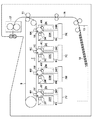
図1は、本実施形態による画像形成装置の構成図である。なお、参照符号の末尾の英文字Y、M、C、Kは、当該参照符号により示される部材が形成に係るトナー像の色が、それぞれ、イエロー(Y)、マゼンタ(M)、シアン(C)、ブラック(K)であることを示している。なお、以下の説明において、トナーの色を区別する必要が無い場合には、末尾の英文字Y、M、C、Kを除いた参照符号を使用する。画像形成装置は、画像形成装置から着脱自在なプロセスカートリッジ5を有する。プロセスカートリッジ5は、それぞれ、トナー容器23と、像担持体である感光体1と、帯電ローラ2と、現像ローラ3を含む現像部と、クリーニングブレード4と、廃トナー容器24と、を備えている。
<First embodiment>
FIG. 1 is a configuration diagram of the image forming apparatus according to the present embodiment. Note that the English letters Y, M, C, and K at the end of the reference numerals indicate the colors of the toner images formed by the members indicated by the reference numerals, respectively yellow (Y), magenta (M), and cyan (C ), Black (K). In the following description, when it is not necessary to distinguish the color of the toner, reference numerals excluding the alphabetical characters Y, M, C, and K at the end are used. The image forming apparatus includes a process cartridge 5 that is detachable from the image forming apparatus. Each of the process cartridges 5 includes a
画像形成時、感光体1は、図中の矢印の方向に回転駆動される。帯電ローラ2は、負極性の帯電バイアスを出力して感光体1の表面を一様な電位に帯電させる。露光部7は、形成する画像に応じた光で感光体1の表面を露光し、感光体1に静電潜像を形成する。現像ローラ3は、現像バイアスを出力し、感光体1との対向領域において、トナー容器23に収容されたトナー(現像剤)で感光体1の静電潜像を現像しトナー像(現像剤像)として可視化する。一次転写ローラ6は、一次転写バイアスを出力し、感光体1のトナー像を中間転写体8に転写する。なお、感光体1Y、1M、1C、1Kのトナー像を重ねて中間転写体8に転写することで多色のトナー像が形成される。中間転写体8に転写されず感光体1に残留したトナーは、クリーニングブレード4により廃トナー容器24に回収される。
At the time of image formation, the
像担持体である中間転写体8は、3つのローラにより張架され、図中の矢印Zの方向に回転駆動される。したがって、中間転写体8に転写されたトナー像は、中間転写体の回転により、二次転写ローラ11の対向位置へと搬送される。一方、給紙カセット13の記録材15は、搬送路16に沿って二次転写ローラ11の対向位置へと搬送される。なお、記録材15は、搬送路16に沿って設けられたローラにより搬送される。二次転写ローラ11は、二次転写バイアスを出力し、中間転写体8のトナー像を記録材15に転写する。記録材15は、その後、定着部17へと搬送される。定着部17は、記録材15を加熱・加圧して、トナー像を記録材15に定着させる。トナー像の定着後、記録材15は画像形成装置外に排出される。
The
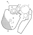
図2は、プロセスカートリッジ5の詳細を示している。現像部30は、現像室33とトナー容器23を有する。トナー容器23の内部には、トナー40が収容されている。また、トナー容器23には、トナー40を現像室33に搬送するための搬送部材34が設けられている。搬送部材34は、図中の矢印Gの方向へ回転駆動され、これにより、トナー40を現像室33へと搬送する。現像室33には、感光体1と接触し、図中の矢印Dの方向に回転駆動される現像ローラ3が設けられている。現像ローラ3は、図示しない現像バイアス印加部から印加される現像バイアスを出力する。さらに、現像室33には、トナー容器23から搬送されたトナー40を現像ローラ3に供給する供給ローラ35と、現像ローラ3上のトナーの量を規制し、かつ、トナーを帯電させる規制部材36が設けられる。供給ローラ35は、現像ローラ3との対向領域において、現像ローラ3と接触しており、図中の矢印Eの方向に回転駆動される。また、供給ローラ35には、図示しない供給バイアス印加部から供給バイアスが印加される。供給バイアスと現像バイアスの電位差に応じて、トナー40には、現像ローラ3に向かう方向への力、或いは、供給ローラ35に向かう方向の力が働く。また、供給ローラ35によって現像ローラ3に供給されたトナー40は、現像ローラ3の回転により、規制部材36と現像ローラ3の当接部へ進入する。トナー40は、現像ローラ3の表面と規制部材36との摺擦により摩擦帯電されると共にその層厚が規制される。帯電したトナー40は、現像ローラ3の回転により、感光体1との対向領域に搬送され、この対向領域において感光体1上の静電潜像に付着される。
FIG. 2 shows details of the process cartridge 5. The developing
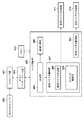
図3は、本実施形態による画像形成装置の制御構成を示す図である。コントローラ部401は、外部のホストコンピュータ400から画像情報と印刷条件を示す画像信号を受け取る。コントローラ部401は、ホストコンピュータ400から受け取った画像信号の画像情報を画像展開し、印刷情報として、ビデオインターフェイス部403経由でメイン制御部402へ送信する。本実施形態における印刷情報は、記録材に転写されるトナー像の濃度情報を含む。なお、濃度情報において、トナー濃度が0%の領域、つまり、トナー像が形成されない領域は、非画像形成領域ということができる。言い換えるならば、画像が形成されない余白は、非画像形成領域に含まれるといえる。また、濃度情報は、非画像形成領域の情報(以下、余白情報ともいう)を含む。
FIG. 3 is a diagram illustrating a control configuration of the image forming apparatus according to the present embodiment. The
メイン制御部402の受信部404は、コントローラ部401が送信する濃度情報を受け取り、供給バイアス制御部407と紙間制御部408に通知する。供給バイアス制御部407は、供給バイアス決定部409とタイミング制御部410を有し、供給ローラ35に供給バイアスを出力する供給バイアス印加部411を制御する。タイミング制御部410は、供給バイアスを変更するタイミングを決定する。また、紙間制御部408は、濃度情報を用いて紙間を決定して紙間を制御する。なお、紙間とは、複数の記録材に画像を形成する際の、先行する記録材と、当該先行する記録材に後続する記録材との間隔である。現像バイアス制御部405は、現像ローラ3に現像バイアスを出力する現像バイアス印加部412を制御する。メモリ419は、記憶部である。なお、本実施形態においてメモリ419は、1つのメモリ装置を指すのではなく、画像形成装置内にある1つ以上のメモリ装置の総称であり、揮発性メモリや、不揮発性メモリを含む。メモリ419には、メイン制御部402が実行するプログラムや、メイン制御部402が制御において使用する各種データが格納される。
The receiving
現像ゴーストは、現像ローラ3上においてトナーの帯電量が変動することで生じる。具体的には、余白形成中、現像ローラ3上のトナーの帯電量は、時間に比例して大きくなる。帯電量が大きくなることで、感光体1の静電潜像に付着するトナーの量が少なくなる。例えば、余白の形成期間が現像ローラ3の1周期以上になると、現像ローラ3の周囲に付着しているトナーの帯電量は大きくなる。結果、その後にベタ画像を形成すると、現像ローラ3上において帯電量が大きくなったトナーの総てが感光体1の静電潜像に供給されるまで、トナー像の濃度が薄くなる。
The development ghost is generated when the toner charge amount fluctuates on the development roller 3. Specifically, during the margin formation, the charge amount of the toner on the developing roller 3 increases in proportion to time. As the charge amount increases, the amount of toner attached to the electrostatic latent image on the
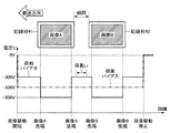
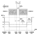
以下、本実施形態における現像ローラ3と供給ローラ35のバイアス制御について説明する。図4は、連続して2枚の記録材に画像形成を行う場合におけるバイアス制御の説明図である。なお、図4の横軸は距離を、縦軸は現像ローラ3と供給ローラ35それぞれの現像バイアス及び供給バイアスを示している。なお、図4の横軸の値は、実際には時間であるが、紙間との関係を説明するために、記録材の搬送速度に基づく距離に変換して示している。なお、図4において、記録材#1に形成する画像Aの後端から記録材#2に形成する画像Bの先端までの距離は、現像ローラ3の周長Lrより長いものとする。なお、以下の説明において、先端、後端とは、記録材の搬送方向の先端、後端を意味するものとし、"長さ"や"距離"とは、記録材の搬送方向における長さや距離を意味するものとする。さらに、現像ローラ3の周長Lrを、単に周長Lrと呼ぶものとする。
Hereinafter, bias control of the developing roller 3 and the
本実施形態において、現像バイアスは、「現像駆動開始」から「現像駆動停止」まで一定値であり、図4の例では、−400Vである。一方、画像A及び画像Bに対応するトナー像を感光体1に形成している間には、供給バイアスを−500Vに設定する。供給バイアスを現像バイアスより低くすることで、トナーには現像ローラ3に向かう力が働き、現像ローラ3にトナーが供給される。一方、「現像駆動開始」から記録材#1の「画像Aの先端」までと、「画像Aの後端」から「画像Bの先端」までと、記録材#2の「画像Bの後端」から「現像駆動停止」までにおいては、供給バイアスを−300Vに設定する。供給バイアスを現像バイアスより高くすることで、トナーには供給ローラ35に向かう力が働き、これによりトナー回収処理が実行される。よって、現像ローラ3のトナーを回収してトナーの帯電量の増加を抑えることができる。なお、図4において、供給バイアスを−300V又は−500Vに設定するタイミングは、実際には、画像Aや画像Bを感光体1において現像するタイミングである。具体的には、図4では、画像Aの後端から画像Bの先端までの間、供給バイアスを−300Vに設定している。これは、画像Aの後端を感光体1に現像してから、画像Bの先端を感光体1に現像し始めるまでの間、供給バイアスを−300Vに設定することを意味する。つまり、図4では、記録材に形成する画像に対応する感光体1の位置が、現像ローラ3との対向領域を通過している間、供給バイアスを−500Vに設定している。また、図4では、紙間及び記録材の余白に対応する感光体1の位置が、現像ローラ3との対向領域を通過している間、供給バイアスを−300Vに設定している。この図面の表現と、供給バイアスの設定タイミングとの関係は、図4と同様の以下の各図においても同じである。
In the present embodiment, the development bias is a constant value from “development drive start” to “development drive stop”, and is −400 V in the example of FIG. On the other hand, while the toner images corresponding to the images A and B are formed on the
なお、ここでは説明を簡略化するために、画像A又は画像Bの端部を基準に供給バイアスを切り替えるとした。しかし、実際の画像形成装置の動作においては、感光体1上にトナーが供給されて静電潜像が画像として現像されるまでには、現像ローラ3と供給ローラ35のニップ部から現像ローラ3と感光ドラム1とのニップ部までトナーが移動する所定期間Tが必要となる。よって、実際の画像形成装置における制御としては、供給バイアスを切り替えるタイミングは、上述した画像の端部に対応したタイミングから所定期間T分だけ前倒ししたタイミングとなる。なお、この所定期間Tは、以下の式に基づき求めることができる。
Here, in order to simplify the description, the supply bias is switched based on the end of the image A or the image B. However, in the actual operation of the image forming apparatus, until the toner is supplied onto the
所定期間T=L/V
ここで、Lは、現像ローラ3の回転方向における現像ローラ3と供給ローラ35とのニップ部から現像ローラ3と感光体1とのニップ部までの距離である。また、Vは、現像ローラ3の回転速度である。よって、上述の供給バイアスの切り替えタイミングは、画像Aの後端を感光体1に現像するより所定期間T分だけ前倒ししたタイミングから、画像Bの先端を感光体1に現像し始めるより所定期間T分だけ前倒ししたタイミングまでの間、供給バイアスを−300Vに設定する、と言い換えることができる。また、記録材に形成する画像の先端に対応する感光体1の位置が、現像ローラ3との対向領域を通過し始めるより所定期間T分だけ前倒ししたタイミングから、記録材に形成する画像の後端に対応する感光体1の位置が、現像ローラ3との対向領域を通過し終わるより所定期間T分だけ前倒ししたタイミングの間、供給バイアスを−500Vに設定する、と言い換えることができる。また、紙間及び記録材の余白の先端に対応する感光体1の位置が、現像ローラ3との対向領域を通過し始めるより所定期間T分だけ前倒ししたタイミングから、紙間及び記録材の余白の後端に対応する感光体1の位置が、現像ローラ3との対向領域を通過し終わるより所定期間T分だけ前倒ししたタイミングの間、供給バイアスを−300Vに設定する、と言い換えることができる。以下では、説明が煩雑になるため、この所定期間Tに関する記載は省略して説明を行う。
Predetermined period T = L / V
Here, L is the distance from the nip portion between the developing roller 3 and the
図5及び図6は、本実施形態によるバイアス制御の説明図である。図5及び図6において、記録材の搬送方向におけるトナー濃度は均一とする。なお、ここでは一例としてイエローの画像形成を例にして説明するが、マゼンタ、シアン、ブラックの夫々の色でも同様の制御を行うことができる。また、以下の説明において、現像バイアスをGvとし、トナー回収処理時の供給バイアスをRhとし、現像ローラ3にトナーを供給するための供給バイアスをRvとする。例えば、図4の例では、Gv=−400V、Rh=−300V、Rv=−500Vである。 5 and 6 are explanatory diagrams of bias control according to the present embodiment. 5 and 6, the toner density in the recording material conveyance direction is uniform. Here, yellow image formation is described as an example here, but the same control can be performed for each of magenta, cyan, and black. In the following description, the developing bias is Gv, the supply bias at the time of toner recovery processing is Rh, and the supply bias for supplying toner to the developing roller 3 is Rv. For example, in the example of FIG. 4, Gv = −400V, Rh = −300V, and Rv = −500V.
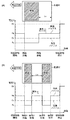
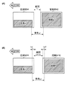
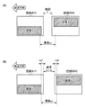
図5(A)は、記録材の画像の後端にある余白、つまり、非画像領域の長さLeが現像ローラ3の周長Lr以上の場合を示している。非画像領域の長さLeが、所定長以上、つまり周長Lr以上であると、メイン制御部402は、余白の開始から現像部の駆動停止まで、つまり、画像の後端から現像部の駆動停止までトナー回収処理を行う。図5(B)は、画像Aと画像Bの間にある余白の長さLeが現像ローラ3の周長Lr以上の場合を示している。この場合、メイン制御部402は、余白の開始(画像A後端)から余白の終了(画像Bの先端)までトナー回処理を行う。
FIG. 5A shows a case where the margin at the rear end of the image of the recording material, that is, the length Le of the non-image area is equal to or larger than the circumferential length Lr of the developing roller 3. When the length Le of the non-image area is not less than a predetermined length, that is, not less than the circumferential length Lr, the
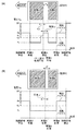
図6(A)は、記録材内の画像Aと画像Bの間の余白の長さLeが現像ローラ3の周長Lr未満で、かつ、画像Aのトナー濃度Dcが閾値未満である場合を示している。なお、本実施形態では、トナー濃度Dcが一定であるものとしているが、トナー濃度Dcが変化する場合には、例えば、最大値、平均値、最小値等を使用する。この場合、メイン制御部402は、周長Lrから余白の長さLeを減じた長さLdを求め、画像Aの後端から先端方向に向かって長さLdの区間を区間Ldとし、区間Ldの濃度を濃度情報から求める。なお、区間Ldの濃度が変化する場合には、最大値、平均値、最小値等を使用する。メイン制御部402は、区間Ldの濃度に基づき、区間Ldにおける供給バイアスRsを、以下の式(1)により求める。
FIG. 6A shows a case where the length Le of the margin between the image A and the image B in the recording material is less than the circumferential length Lr of the developing roller 3 and the toner density Dc of the image A is less than the threshold value. Show. In this embodiment, the toner density Dc is assumed to be constant, but when the toner density Dc changes, for example, a maximum value, an average value, a minimum value, or the like is used. In this case, the
Rs=Rh−(|Gv−Rh|×α) (1)
ここで、αは、区間Ldの濃度に応じ、0より大きく、かつ、1以下の値を取る補正係数である。なお、補正係数αは、例えば、区間Ldの濃度が大きいほど大きくなるよう設定することができる。これは、濃度が高い場合には、供給バイアスをトナー回収処理実行時の値Rhに近づけるほど、画像の濃度ムラが目立ちやすくなるからである。
補正係数αは、式(2)に示す様に、閾値Thと、区間Ldの濃度Dldの関数として求めることができる。
Rs = Rh− (| Gv−Rh | × α) (1)
Here, α is a correction coefficient that takes a value greater than 0 and 1 or less in accordance with the density of the section Ld. For example, the correction coefficient α can be set to increase as the density of the section Ld increases. This is because, when the density is high, the density unevenness of the image becomes more conspicuous as the supply bias is brought closer to the value Rh at the time of toner collection processing.
The correction coefficient α can be obtained as a function of the threshold Th and the density Dld of the section Ld as shown in the equation (2).
α=Dld/Th 0<Dld<Th (2)
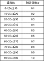
また、図7に示す様な濃度Dcと補正係数αの関係を示す情報を予めメモリ419に保持させておき、この情報により補正係数αを求める構成とすることもできる。なお、図7においては閾値を100としている。図6(A)に戻り、メイン制御部402は、区間Ldにおいて、供給バイアスをRsに設定し、その後、画像Aの後端から画像Bの先端までは供給バイアスをRhに設定する。なお、式(1)より区間Ldにおいてもトナー回収処理が実行される。しかしながら、供給バイアスRsと現像バイアスGvとの差は、補正係数αが1である場合を除き、供給バイアスRhと現像バイアスGvとの差より小さい。したがって、区間Ldにおいてトナーに働く供給ローラ35方向の力は、紙間の時よりも弱くなる。
α = Dld / Th 0 <Dld <Th (2)
In addition, information indicating the relationship between the density Dc and the correction coefficient α as shown in FIG. 7 may be stored in the
図6(B)は、画像Aから画像Bまでの余白の長さLeが現像ローラ3の周長Lr未満であり、かつ、画像Aの濃度Dcが閾値以上である場合を示している。この場合、余白領域においてトナー回収処理を行わず、よって、供給バイアスは、余白の間もRvに設定する。これは、画像Aのトナー濃度が閾値以上の場合、画像Aの後端を現像した後には、現像ローラ3に残留しているトナーが少なく、かつ、画像間の期間も短いことから、帯電量が変化するトナーが少ないからである。つまり、画像Bに現像ゴーストが発生し難いからである。 FIG. 6B shows a case where the length Le of the margin from the image A to the image B is less than the circumferential length Lr of the developing roller 3 and the density Dc of the image A is greater than or equal to the threshold value. In this case, toner collection processing is not performed in the margin area, and therefore the supply bias is set to Rv even during the margin. This is because when the toner density of the image A is equal to or higher than the threshold value, the toner remaining on the developing roller 3 is small after the rear end of the image A is developed, and the period between the images is also short. This is because there is little toner that changes. That is, the development ghost hardly occurs in the image B.
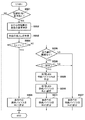
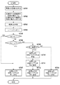
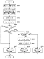
図8は、メイン制御部402における処理のフローチャートである。メイン制御部402は、S501で、記録材内に余白があるか否かを判定する。余白が無いと、メイン制御部402は、トナー回収処理は必要ないとして処理を終了する。一方、余白があると、メイン制御部402は、S502で、余白の先端側にある画像の濃度Dを判定する。さらに、メイン制御部402は、S503で、当該余白の長さLeを判定する。メイン制御部402は、S504で、余白の長さLeと、周長Lrを比較する。余白の長さLeが、周長Lr以上であると、メイン制御部402は、図5を用いて説明した様に、S505で、余白の間の供給バイアスを、トナー回収処理に対応するRhに設定する。なお、余白の間の供給バイアスとは、上述した様に、記録材に余白を形成するために感光体1においてトナー像を形成していない間の供給バイアスとの意味である。余白の長さLeが周長Lr未満であると、メイン制御部402は、S506で余白後に画像があるか否かを判定する。余白後に画像が無ければ現像ゴーストを懸念する必要がない。したがって、メイン制御部402は、S507で、余白での供給バイアスをRvに設定する。一方、余白後に画像があると、メイン制御部402は、S508で、余白前の画像の濃度Dと閾値を比較する。濃度Dが閾値以上であると、図6(B)で説明した様に、トナー回収動作を行う必要がないため、メイン制御部402は、S507で、余白での供給バイアスをRvに設定する。濃度Dが閾値未満であると、メイン制御部402は、図6(A)で説明した様に、S509で、長さLd及び区間Ldと、区間Ldにおける供給バイアスRsを式(1)で求める。メイン制御部402は、S510で、区間Ldでの供給バイアスをRsに設定し、S511で、余白での供給バイアスをRhに設定する。図8の処理は、記録材の先端から後端まで繰り返す。
FIG. 8 is a flowchart of processing in the
なお、ここでは供給ローラ35Yに設定する供給バイアスの求め方について説明した。供給ローラ35Yに設定する供給バイアスを基準に、他の色の供給ローラ35M、35C及び35Kに設定する供給バイアスも同じバイアスと設定してもよい。もちろん、イエロー以外の色を基準にしてもよい。 Here, the method for obtaining the supply bias set for the supply roller 35Y has been described. Based on the supply bias set for the supply roller 35Y, the supply bias set for the supply rollers 35M, 35C, and 35K of other colors may be set to the same bias. Of course, colors other than yellow may be used as a reference.
また、色毎に画像領域と非画像領域を判定する構成とすることもできる。つまり、記録材に形成する画像を色毎に判定して画像領域と非画像領域を判定する構成とすることもできる。この場合、色毎に非画像領域の長さは異なることがあり、よって、供給ローラ35Y、35M、35C及び35Kに設定する供給バイアスは独立して制御される。つまり、例えば、供給ローラ35Y及び35Mの供給バイアスをRhに設定している際に、供給ローラ35C及び35Kの供給バイアスをRvに設定することが生じ得る。なお、色毎に判定する構成においては、感光体1の回転方向において、感光体1に静電潜像を形成する領域が画像領域であり、2つの画像領域の間の静電潜像を形成しない領域が非画像領域となる。そして、メイン制御部402は、感光体1の回転方向における非画像領域の長さに応じて、当該非画像領域が現像ローラ3との対向領域を通過している間の供給バイアスを制御する。
Moreover, it can also be set as the structure which determines an image area | region and a non-image area | region for every color. That is, an image formed on the recording material can be determined for each color, and an image area and a non-image area can be determined. In this case, the length of the non-image area may be different for each color, and therefore the supply bias set to the supply rollers 35Y, 35M, 35C, and 35K is controlled independently. That is, for example, when the supply bias of the supply rollers 35Y and 35M is set to Rh, the supply bias of the supply rollers 35C and 35K may be set to Rv. In the configuration for determining each color, an area where an electrostatic latent image is formed on the
なお、余白後の画像のトナー濃度が薄い程、現像ゴーストは目立ちにくい。したがって、余白後の画像のトナー濃度に応じて供給バイアスを変化させる構成とすることもできる。 Note that the development ghost is less noticeable as the toner density of the image after the margin is lower. Accordingly, the supply bias can be changed according to the toner density of the image after the margin.
以上、記録材に形成する画像のトナー濃度と余白の長さに応じて、記録材に画像を形成している間における供給バイアスを制御する。この構成により、記録材内において余白と画像が混在する場合においても現像ゴーストの発生を抑制することが可能となる。 As described above, the supply bias during the image formation on the recording material is controlled according to the toner density and the margin length of the image formed on the recording material. With this configuration, it is possible to suppress the development ghost from occurring even when margins and images are mixed in the recording material.
<第二実施形態>
以下、本実施形態について第一実施形態との相違点を中心に説明する。第一実施形態では、1つの記録材内における画像領域と非画像領域の搬送方向の長さに応じた供給バイアスの制御方法を開示していた。本実施形態では、記録材間における供給バイアスの制御方法を開示する。以下では、記録材#1と、記録材#1に続いて画像形成が行われる記録材#2に対する供給バイアスの設定について説明する。なお、記録材#1と記録材#2の紙間は、所定の基準値Liであるものとする。また、記録材#1の最も後ろ側にある画像を画像Aとし、記録材#2の最も前側にある画像を画像Bとする。
<Second embodiment>
Hereinafter, the present embodiment will be described focusing on differences from the first embodiment. In the first embodiment, a supply bias control method corresponding to the length of the image area and the non-image area in one recording material in the transport direction is disclosed. In the present embodiment, a method for controlling a supply bias between recording materials is disclosed. Hereinafter, setting of the supply bias for the
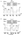
図9(A)は、記録材#1の後端側に長さLe1の余白が存在し、記録材#2の先端に長さLe2の余白が存在し、長さLe1と、紙間Liと、長さLe2の和が、現像ローラ3の周長Lr以上の場合を示しいている。この場合、図9(A)に示す様に、記録材#1の後端側の余白開始から、記録材#2の先端側の余白終了まで供給バイアスをRhに設定してトナー回収処理を実行する。
In FIG. 9A, a margin of length Le1 exists on the rear end side of the
図9(B)は、長さLe1と、紙間Liと、長さLe2の和が現像ローラ3の周長Lr未満であり、かつ、記録材#1の余白開始直前の画像Aの濃度Dが閾値未満である場合を示している。この場合、メイン制御部402は、周長Lrから長さLe1と、紙間Liと、長さLe2の和を減じた長さLdを求め、画像Aの後端から先端方向の長さLdの区間を区間Ldとする。メイン制御部402は、区間Ldの濃度に基づき、式(1)により区間Ldでの供給バイアスRsを求める。そして、図9(B)に示す様に、区間Ldにおいては、供給バイアスをRsに設定し、記録材#1の画像Aの後端から記録材#2の画像Bの先端までは、供給バイアスをRhに設定する。
FIG. 9B shows the density D of the image A immediately before the start of the margin of the
図10は、長さLe1と、紙間Liと、長さLe2の和が現像ローラ3の周長Lr未満であり、かつ、記録材#1の余白領域開始直前の画像Aの濃度Dが閾値以上である場合を示している。この場合、図10に示す様に、トナー回収動作を行わず、よって、余白及び紙間において供給バイアスをRvに設定する。
FIG. 10 shows that the sum of the length Le1, the sheet interval Li, and the length Le2 is less than the circumferential length Lr of the developing roller 3, and the density D of the image A immediately before the start of the blank area of the
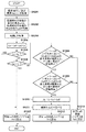
図11は、本実施形態によるメイン制御部402における処理のフローチャートである。メイン制御部402は、S701で、画像Aの濃度Dを判定し、S702で、記録材#1の後端側の余白の長さLe1と、記録材#2の先端側の余白の長さLe2を判定する。メイン制御部402は、S703で、紙間Liを判定し、S704で、長さLe1、紙間Li、長さLe2の和であるLaを求める。また、画像Aの後端から画像Bの先端までの区間を区間Laとする。メイン制御部402は、S705で、紙間Liと周長Lrを比較する。紙間Liが周長Lr以上であると、メイン制御部402は、図9(A)に示す様に、S707で、区間Laにおいてトナー回収処理を実行すべく、供給バイアスをRhに設定する。一方、紙間Liが周長Lr未満であると、メイン制御部402は、S706で、長さLaと周長Lrを比較する。長さLaが周長Lr以上であると、メイン制御部402は、S707で区間Laでの供給バイアスをRhに設定する。一方、長さLaが周長Lr未満であると、メイン制御部402は、S708で濃度Dを閾値と比較する。濃度Dが閾値以上であると、メイン制御部402は、図10を用いて説明した様に。区間Laにおいてトナー回収処理を行わない。したがって、メイン制御部402は、S709で、区間Laでの供給バイアスをRvに設定する。一方、濃度Dが閾値未満であると、メイン制御部402は、図9(B)を用いて説明した様に、S710で長さLd及び区間Ldを求め、式(1)により区間Ldの供給バイアスRsを算出する。メイン制御部402は、S711で区間Ldの供給バイアスをRsに設定し、S712で区間Laの供給バイアスをRhに設定する。
FIG. 11 is a flowchart of processing in the
以上、連続する記録材間の紙間と、先行する記録材の後端側の余白の長さと、後続する記録材の先端側の余白の長さにより、供給バイアスを制御する。この構成により、現像ゴーストの発生を抑制することが可能となる。なお、紙間においては画像が形成されない。つまり、本実施形態は、先行する記録材の後端側の余白と、後続する記録材の先端側の余白と、紙間とを纏めて1つの非画像領域とする以外は、第一実施形態と同様である。 As described above, the supply bias is controlled according to the interval between the continuous recording materials, the length of the trailing edge of the preceding recording material, and the length of the leading edge of the succeeding recording material. With this configuration, it is possible to suppress the development ghost. Note that no image is formed between the sheets. That is, the present embodiment is the first embodiment except that the margin on the trailing edge side of the preceding recording material, the margin on the leading edge side of the succeeding recording material, and the gap between the sheets are combined into one non-image area. It is the same.
<第三実施形態>
続いて、本実施形態について、第二実施形態との相違点を中心に説明する。図12(A)の記録材#1の様に、搬送方向に向かって左半分のみに画像が形成され、右半分が余白である場合において、画像内や余白でトナー回収処理を行うと、画像Aの濃度が変化して画像品質が低下し得る。本実施形態においては、画像品質を優先し、トナー濃度に応じて、図12(B)に示す様に、記録材間の紙間を基準値であるLiからΔLだけ広げる。
<Third embodiment>
Subsequently, the present embodiment will be described focusing on differences from the second embodiment. When the image is formed only in the left half in the transport direction and the right half is a blank as in the
図13は、本実施形態によるメイン制御部402における処理のフローチャートである。図13のS901〜S909までの処理は、図11のS701〜S709までの処理と同様である。本実施形態では、第二実施形態と異なり、S908で濃度Dが閾値未満であると、メイン制御部402の紙間制御部408は、周長Lrから、長さLe1、Li及びLe2を減じた値をΔLとして求め、S911で紙間をLiからΔLだけ広げる。そして、メイン制御部402の供給バイアス制御部407は、紙間を広げた後の区間Laでの供給バイアスをRhとしてトナー回収処理を実行する。
FIG. 13 is a flowchart of processing in the
<第四実施形態>
続いて、本実施形態について第二実施形態との相違点を中心に説明する。図14(A)に示す様に、先行する記録材#1では、搬送方向に向かって左半分に閾値以上の濃度の画像Aを形成し、後続する記録材#2では、搬送方向に向かって右半分に閾値以上の濃度の画像Bを形成する場合を考える。この場合に、画像内や余白でトナー回収処理を行うと、画像A及び画像Bのいずれか、或いは、両方の濃度が変化して画像品質が低下し得る。本実施形態においては、画像品質を優先し、画像の濃度に応じて、図14(B)に示す様に、記録材間の紙間をΔLだけ広げる。
<Fourth embodiment>
Subsequently, the present embodiment will be described focusing on differences from the second embodiment. As shown in FIG. 14A, the preceding
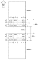
本実施形態では、図15に示す様に、周長Lrから紙間Liを減じた長さをLsと定義する。そして、記録材#1については、後端から先端方向へ長さLsまでの部分を後端部分とし、記録材#2については、先端から後端方向へ長さLsまでの部分を前端部分と定義する。そして、後端部分をn×m個の領域B[1][1]〜B[m][n]に分割する。また、前端部分をn×m個の領域A[1][1]〜A[m][n]に分割する。本実施形態では、後端部分及び前端部分それぞれについて、搬送方向においては長さbでm個に分割し、搬送方向と直交する方向においては長さaでn個に分割している。また、本実施形態では、領域B[i][j]及び領域A[i][j](iは1〜mの整数、jは1〜nの整数)のサイズは同じであるが、領域毎にサイズを異ならせても良い。
In the present embodiment, as shown in FIG. 15, the length obtained by subtracting the inter-paper Li from the circumferential length Lr is defined as Ls. For
本実施形態においてメイン制御部402は、非画像領域より上流側の領域B[i][j]それぞれの濃度Db[i][j]と、下流側の領域A[i][j]の濃度Da[i][j]を判定する。そして、濃度Db[i][1]〜濃度Db[i][n]の内の、最小濃度と最大濃度を判定する。つまり、搬送方向と直交する方向(以下、直交方向)における濃度の変化を判定する。最大濃度が閾値以上で、かつ、最小濃度が閾値未満の場合、直交方向における濃度が一定ではなく、かつ、閾値を跨ぐ濃度変化が存在することになる。つまり、記録材#1に形成される画像が、図14(A)に示す様なものである可能性がある。この場合、メイン制御部402は、濃度Da[i][1]〜濃度Da[i][n]の内の、最小濃度と最大濃度を判定する。最大濃度が閾値以上で、かつ、最小濃度が閾値未満の場合、直交方向における濃度が一定ではなく、かつ、閾値を跨ぐ濃度変化が存在することになる。つまり、記録材#2に形成される画像が、図14(A)に示す様なものである可能性がある。この場合、紙間制御部408は、図14(B)に示す様に紙間を広げる。
In the present embodiment, the
図16は、本実施形態によるメイン制御部402における処理のフローチャートである。メイン制御部402は、S1201で濃度Db[i][j]と濃度Da[i][j]を取得し、S1202で、記録材#1後端の余白の長さLe1及び記録材#2先端の余白の長さLe2を取得し、S1203で紙間Liを取得する。メイン制御部402は、S1204で、余白の長さLe1と、紙間Liと、余白の長さLe2の和Laを求める。また、記録材#1後端の余白開始から、記録材#2先端の余白終了までの区間を区間Laと定義する。メイン制御部402は、S1205で、紙間Liと周長Lrを比較する。紙間Liが周長Lr以上であると、メイン制御部402は、S1207で区間Laの供給バイアスをRhに設定する。一方、紙間Liが周長Lr未満であると、メイン制御部402は、S1206で、長さLaと周長Lrを比較する。長さLaが周長Lr以上であると、メイン制御部402は、S1207で区間Laの供給バイアスをRhに設定する。
FIG. 16 is a flowchart of processing in the
一方、長さLaが周長Lr未満であると、メイン制御部402は、S1208で、i=1〜mのいずれかで、濃度Db[i][1]〜濃度Db[i][n]の内の最小濃度と最大濃度が閾値を跨いでいるかを判定する。最小濃度と最大濃度が閾値を跨いでいないと、S1213で、区間Laの供給バイアスをRvに設定する。一方、閾値を跨いでいると、メイン制御部402は、S1209で、i=1〜mのいずれかで、濃度Da[i][1]〜濃度Da[i][n]の内の最小濃度と最大濃度が閾値を跨いでいるかを判定する。最小濃度と最大濃度が跨いでいないと、S1213で、区間Laの供給バイアスをRvに設定する。一方、最大濃度と最小濃度が閾値を跨いでいると、図14(A)の様な状態である可能性がある。したがって、メイン制御部402は、S1210で、周長Lrから長さLe1、Li及びLe2を減じた値ΔLを求め、S1211で、記録材#1と記録材#2の紙間をΔLだけ広げる。そして、メイン制御部402は、S1212で、区間Laの供給バイアスをRhに設定する。
On the other hand, if the length La is less than the circumferential length Lr, the
以上、画像濃度が、記録材の搬送方向と直交する方向において変化している場合でも、現像ゴーストの発生を抑制することが可能となる。 As described above, even when the image density changes in the direction orthogonal to the recording material conveyance direction, it is possible to suppress the development ghost.
[その他の実施形態]
なお、上記実施形態では、色毎に記録材に形成される画像について、画像領域と、紙間を含む非画像領域を判定し、供給バイアスを制御していた。しかしながら、例えば画像形成に使用するY、M、C、Kを重ねた画像に基づき画像領域と非画像領域を判定することもできる。この場合、対象となる画像が異なるだけで、供給バイアスの判断の仕方は、上記実施形態と同様である。また、供給ローラ35Y、35M、35C及び35Kに設定する供給バイアスは同じとなる。
[Other Embodiments]
In the above-described embodiment, for the image formed on the recording material for each color, the image area and the non-image area including the gap between the sheets are determined, and the supply bias is controlled. However, for example, an image area and a non-image area can be determined based on an image obtained by superimposing Y, M, C, and K used for image formation. In this case, only the target image is different, and the method of determining the supply bias is the same as in the above embodiment. Further, the supply bias set to the supply rollers 35Y, 35M, 35C, and 35K is the same.
また、上述した実施形態では、非画像領域の長さにより説明したが、記録材の搬送速度と距離(長さ)から、時間が求められるため、メイン制御部402による供給バイアスの設定制御は、そのタイミングとして規定することもできる。
In the above-described embodiment, the length of the non-image area has been described. However, since the time is obtained from the conveyance speed and distance (length) of the recording material, the supply bias setting control by the
本発明は、上述の実施形態の1以上の機能を実現するプログラムを、ネットワーク又は記憶媒体を介してシステム又は装置に供給し、そのシステム又は装置のコンピュータにおける1つ以上のプロセッサーがプログラムを読出し実行する処理でも実現可能である。また、1以上の機能を実現する回路(例えば、ASIC)によっても実現可能である。 The present invention supplies a program that realizes one or more functions of the above-described embodiments to a system or apparatus via a network or a storage medium, and one or more processors in a computer of the system or apparatus read and execute the program This process can be realized. It can also be realized by a circuit (for example, ASIC) that realizes one or more functions.
1:感光体、3:現像ローラ、33:供給ローラ、402:メイン制御部 1: Photoconductor, 3: Developing roller, 33: Supply roller, 402: Main control unit
Claims (18)
前記像担持体との対向領域において、前記像担持体に形成された静電潜像を現像剤により現像して現像剤像を形成する現像手段と、
供給バイアスを出力して、前記現像手段への現像剤の供給と、前記現像手段からの現像剤の回収を行う供給手段と、
前記像担持体の回転方向における現像剤像が形成されない非画像領域の長さに基づき前記供給バイアスを制御する制御手段と、
を備えていることを特徴とする画像形成装置。 An image carrier that is rotationally driven to form an electrostatic latent image;
Developing means for developing a latent electrostatic image formed on the image carrier with a developer in a region facing the image carrier to form a developer image;
A supply unit that outputs a supply bias to supply the developer to the developing unit and to collect the developer from the developing unit;
Control means for controlling the supply bias based on the length of a non-image area where a developer image is not formed in the rotation direction of the image carrier;
An image forming apparatus comprising:
前記制御手段は、前記回転方向において、前記後端部分の長さを前記所定長及び前記非画像領域の前記長さに応じて決定することを特徴とする請求項3又は4に記載の画像形成装置。 When the length of the non-image area is shorter than the predetermined length and the density of the developer image in the image area upstream of the non-image area in the rotation direction is smaller than a threshold value, the control means In the direction, the position corresponding to the rear end portion of the image area where the developer image upstream of the non-image area is formed and the position of the image carrier corresponding to the non-image area are opposed to the developing means. The supply bias is controlled so as to collect the developer from the developing unit from the timing advanced by a predetermined period from the start of passing through the region to the timing advanced by the predetermined period from completion of passing.
5. The image formation according to claim 3, wherein the control unit determines, in the rotation direction, a length of the rear end portion according to the predetermined length and the length of the non-image area. apparatus.
前記制御手段は、前記非画像領域の前記長さが前記所定長より短く、かつ、前記回転方向において前記非画像領域より上流側の現像剤像が形成される画像領域の現像剤像の濃度が閾値より小さいと、前記先行する記録材と前記後続する記録材の間隔を基準値より広げることを特徴とする請求項3又は4に記載の画像形成装置。 The non-image area is an area extending from a preceding recording material to a subsequent recording material,
The control means is configured such that the density of the developer image in the image area where the length of the non-image area is shorter than the predetermined length and the developer image on the upstream side of the non-image area in the rotation direction is formed. 5. The image forming apparatus according to claim 3, wherein, when smaller than the threshold value, an interval between the preceding recording material and the succeeding recording material is made larger than a reference value.
前記制御手段は、前記非画像領域の前記長さが前記所定長より短いと、前記回転方向において前記非画像領域より上流側の現像剤像が形成される画像領域の後端部分の第1現像剤像の濃度の前記回転方向と直交する直交方向における変化と、前記回転方向において前記非画像領域より下流側の現像剤像が形成される画像領域の前端部分の第2現像剤像の濃度の前記直交方向における変化を判定し、前記第1現像剤像の濃度の変化と、前記第2現像剤像の濃度の変化が共に閾値を跨いでいると、前記先行する記録材と前記後続する記録材の間隔を基準値より広げることを特徴とする請求項3又は4に記載の画像形成装置。 The non-image area is an area extending from a preceding recording material to a subsequent recording material,
When the length of the non-image area is shorter than the predetermined length, the control means performs first development of a rear end portion of the image area in which a developer image upstream of the non-image area is formed in the rotation direction. The change in the density of the developer image in the orthogonal direction orthogonal to the rotation direction, and the density of the second developer image in the front end portion of the image area where the developer image downstream from the non-image area is formed in the rotation direction. The change in the orthogonal direction is determined, and if the change in the density of the first developer image and the change in the density of the second developer image both cross the threshold, the preceding recording material and the subsequent recording 5. The image forming apparatus according to claim 3, wherein the interval between the materials is wider than a reference value.
前記所定長は、前記現像ローラの周長であることを特徴とする請求項3から14のいずれか1項に記載の画像形成装置。 The developing means is a developing roller;
The image forming apparatus according to claim 3, wherein the predetermined length is a circumferential length of the developing roller.
前記制御手段は、現像剤像が形成される画像領域と前記非画像領域を、それぞれ、記録材に形成する画像の色毎に判定し、各供給手段の供給バイアスを独立して設定することを特徴とする請求項1から15のいずれか1項に記載の画像形成装置。 The image carrier, the developing unit, and the supplying unit are provided corresponding to each color used for image formation,
The control means determines the image area where the developer image is formed and the non-image area for each color of the image formed on the recording material, and sets the supply bias of each supply means independently. The image forming apparatus according to claim 1, wherein the image forming apparatus is an image forming apparatus.
Priority Applications (2)
| Application Number | Priority Date | Filing Date | Title |
|---|---|---|---|
| JP2015045086A JP6543051B2 (en) | 2015-03-06 | 2015-03-06 | Image forming device |
| US15/058,596 US9964889B2 (en) | 2015-03-06 | 2016-03-02 | Image forming apparatus that controls supply bias for supplying and collecting developer |
Applications Claiming Priority (1)
| Application Number | Priority Date | Filing Date | Title |
|---|---|---|---|
| JP2015045086A JP6543051B2 (en) | 2015-03-06 | 2015-03-06 | Image forming device |
Publications (3)
| Publication Number | Publication Date |
|---|---|
| JP2016164635A true JP2016164635A (en) | 2016-09-08 |
| JP2016164635A5 JP2016164635A5 (en) | 2018-04-12 |
| JP6543051B2 JP6543051B2 (en) | 2019-07-10 |
Family
ID=56850621
Family Applications (1)
| Application Number | Title | Priority Date | Filing Date |
|---|---|---|---|
| JP2015045086A Active JP6543051B2 (en) | 2015-03-06 | 2015-03-06 | Image forming device |
Country Status (2)
| Country | Link |
|---|---|
| US (1) | US9964889B2 (en) |
| JP (1) | JP6543051B2 (en) |
Cited By (1)
| Publication number | Priority date | Publication date | Assignee | Title |
|---|---|---|---|---|
| JP2018180522A (en) * | 2017-04-10 | 2018-11-15 | キヤノン株式会社 | Image forming device |
Families Citing this family (1)
| Publication number | Priority date | Publication date | Assignee | Title |
|---|---|---|---|---|
| JP2024179562A (en) * | 2023-06-15 | 2024-12-26 | キヤノン株式会社 | Image forming device |
Citations (5)
| Publication number | Priority date | Publication date | Assignee | Title |
|---|---|---|---|---|
| JPH0915976A (en) * | 1995-04-28 | 1997-01-17 | Ricoh Co Ltd | Developing device |
| JPH11125972A (en) * | 1997-10-20 | 1999-05-11 | Ricoh Co Ltd | Image forming device |
| US20060222390A1 (en) * | 2005-04-04 | 2006-10-05 | Samsung Electronics Co., Ltd. | Electrophotographic image forming device and developing method thereof |
| JP2010243885A (en) * | 2009-04-08 | 2010-10-28 | Seiko Epson Corp | Developing device and image forming apparatus |
| JP2013025061A (en) * | 2011-07-21 | 2013-02-04 | Kyocera Document Solutions Inc | Image forming apparatus capable of printing long sheet |
Family Cites Families (5)
| Publication number | Priority date | Publication date | Assignee | Title |
|---|---|---|---|---|
| JPH0973217A (en) | 1995-06-29 | 1997-03-18 | Ricoh Co Ltd | Two-stage development system |
| JP2003084565A (en) | 2001-09-12 | 2003-03-19 | Fuji Xerox Co Ltd | Image forming apparatus |
| JP4624446B2 (en) * | 2008-05-28 | 2011-02-02 | 株式会社沖データ | Image forming apparatus and image forming method |
| JP6135990B2 (en) | 2013-02-22 | 2017-05-31 | 株式会社リコー | Image forming apparatus |
| JP2016177155A (en) * | 2015-03-20 | 2016-10-06 | 株式会社沖データ | Image forming apparatus |
-
2015
- 2015-03-06 JP JP2015045086A patent/JP6543051B2/en active Active
-
2016
- 2016-03-02 US US15/058,596 patent/US9964889B2/en active Active
Patent Citations (5)
| Publication number | Priority date | Publication date | Assignee | Title |
|---|---|---|---|---|
| JPH0915976A (en) * | 1995-04-28 | 1997-01-17 | Ricoh Co Ltd | Developing device |
| JPH11125972A (en) * | 1997-10-20 | 1999-05-11 | Ricoh Co Ltd | Image forming device |
| US20060222390A1 (en) * | 2005-04-04 | 2006-10-05 | Samsung Electronics Co., Ltd. | Electrophotographic image forming device and developing method thereof |
| JP2010243885A (en) * | 2009-04-08 | 2010-10-28 | Seiko Epson Corp | Developing device and image forming apparatus |
| JP2013025061A (en) * | 2011-07-21 | 2013-02-04 | Kyocera Document Solutions Inc | Image forming apparatus capable of printing long sheet |
Cited By (2)
| Publication number | Priority date | Publication date | Assignee | Title |
|---|---|---|---|---|
| JP2018180522A (en) * | 2017-04-10 | 2018-11-15 | キヤノン株式会社 | Image forming device |
| JP7118671B2 (en) | 2017-04-10 | 2022-08-16 | キヤノン株式会社 | image forming device |
Also Published As
| Publication number | Publication date |
|---|---|
| JP6543051B2 (en) | 2019-07-10 |
| US20160259265A1 (en) | 2016-09-08 |
| US9964889B2 (en) | 2018-05-08 |
Similar Documents
| Publication | Publication Date | Title |
|---|---|---|
| JP4972669B2 (en) | Image forming apparatus | |
| US8824004B2 (en) | Image forming apparatus controlling performance of a functional printing and image forming method thereof | |
| JP4369111B2 (en) | Electrophotographic cluster printing system | |
| JP4649189B2 (en) | Image forming apparatus | |
| JP6543051B2 (en) | Image forming device | |
| JP7091109B2 (en) | Image forming device | |
| JP5941819B2 (en) | Medium feeding control method, medium feeding apparatus, and image forming apparatus | |
| JP2009258432A (en) | Image forming apparatus | |
| JP2004170968A (en) | Image forming device | |
| JP2014085553A (en) | Image forming apparatus | |
| JP2020003718A (en) | Image forming device | |
| JP2004333709A (en) | Developing device | |
| US9086659B2 (en) | Image forming apparatus | |
| JP2017215442A (en) | Image forming apparatus | |
| EP1843221B1 (en) | Image forming apparatus with an intermediate transfer belt of limited speed fluctuations | |
| JP6261204B2 (en) | Image forming apparatus | |
| JP5824890B2 (en) | Image forming system and image forming apparatus | |
| JP2008102204A (en) | Image forming apparatus | |
| JP6482310B2 (en) | Image forming apparatus | |
| JP2014119663A (en) | Image forming apparatus | |
| JP2018017868A (en) | Image forming apparatus | |
| US10558135B1 (en) | Image forming apparatus and carrying control method | |
| CN111221230B (en) | Image forming apparatus and computer-readable recording medium | |
| JP4842768B2 (en) | Image forming apparatus | |
| JP2002357933A (en) | Operating method of electrophotographic printing system |
Legal Events
| Date | Code | Title | Description |
|---|---|---|---|
| A521 | Request for written amendment filed |
Free format text: JAPANESE INTERMEDIATE CODE: A523 Effective date: 20180305 |
|
| A621 | Written request for application examination |
Free format text: JAPANESE INTERMEDIATE CODE: A621 Effective date: 20180305 |
|
| A977 | Report on retrieval |
Free format text: JAPANESE INTERMEDIATE CODE: A971007 Effective date: 20181226 |
|
| A131 | Notification of reasons for refusal |
Free format text: JAPANESE INTERMEDIATE CODE: A131 Effective date: 20190107 |
|
| A521 | Request for written amendment filed |
Free format text: JAPANESE INTERMEDIATE CODE: A523 Effective date: 20190307 |
|
| TRDD | Decision of grant or rejection written | ||
| A01 | Written decision to grant a patent or to grant a registration (utility model) |
Free format text: JAPANESE INTERMEDIATE CODE: A01 Effective date: 20190517 |
|
| A61 | First payment of annual fees (during grant procedure) |
Free format text: JAPANESE INTERMEDIATE CODE: A61 Effective date: 20190614 |
|
| R151 | Written notification of patent or utility model registration |
Ref document number: 6543051 Country of ref document: JP Free format text: JAPANESE INTERMEDIATE CODE: R151 |