JP2016160901A - Tube pump and medical device - Google Patents
Tube pump and medical device Download PDFInfo
- Publication number
- JP2016160901A JP2016160901A JP2015043066A JP2015043066A JP2016160901A JP 2016160901 A JP2016160901 A JP 2016160901A JP 2015043066 A JP2015043066 A JP 2015043066A JP 2015043066 A JP2015043066 A JP 2015043066A JP 2016160901 A JP2016160901 A JP 2016160901A
- Authority
- JP
- Japan
- Prior art keywords
- tube
- liquid
- tube pump
- flow rate
- medical device
- Prior art date
- Legal status (The legal status is an assumption and is not a legal conclusion. Google has not performed a legal analysis and makes no representation as to the accuracy of the status listed.)
- Pending
Links
Images


Abstract
Description
本発明は、チューブポンプと、医療装置とに関する。 The present invention relates to a tube pump and a medical device.
近年、医療機器であるウォータジェットメスに液体を供給するための液体供給装置が、種々、提案されている。特許文献1に記載の液体供給装置では、プランジャーポンプを採用し、プランジャーポンプとウォータジェットメスとの間の流路の一部を変形させることによって、ウォータジェットメスに供給する液体の流量の変動を抑制している。
In recent years, various liquid supply apparatuses for supplying liquid to a water jet knife as a medical device have been proposed. The liquid supply device described in
従来の技術では、液体収容部からウォータジェットメスの先端ノズルまでの間の流路、特に液体供給装置から先端ノズルまでの間の流路内の最大到達圧力を適切に管理したいという要望があった。 In the prior art, there has been a desire to appropriately manage the maximum ultimate pressure in the flow path from the liquid container to the tip nozzle of the water jet knife, particularly in the flow path from the liquid supply device to the tip nozzle. .
本発明は、上述の課題の少なくとも一部を解決するためになされたものであり、以下の形態として実現することが可能である。 SUMMARY An advantage of some aspects of the invention is to solve at least a part of the problems described above, and the invention can be implemented as the following forms.
(1)本発明の一形態は、案内部材に沿って配置されたチューブを押圧部材で押し潰しつつ前記押圧部材を移動させることによって、前記チューブ内の液体を搬送するチューブポンプである。このチューブポンプは、前記案内部材を前記チューブの側に付勢する付勢部材と、前記付勢部材の付勢力を調整する付勢力調整部と、を備えてよい。この形態のチューブポンプによれば、案内部材をチューブの側に付勢する付勢部材の付勢力が、付勢力調整部によって調整されるため、流路内の最大到達圧力を適切に管理できる。 (1) One form of this invention is a tube pump which conveys the liquid in the said tube by moving the said press member, crushing the tube arrange | positioned along a guide member with a press member. The tube pump may include a biasing member that biases the guide member toward the tube, and a biasing force adjusting unit that adjusts a biasing force of the biasing member. According to the tube pump of this aspect, the urging force of the urging member that urges the guide member toward the tube is adjusted by the urging force adjusting unit, so that the maximum ultimate pressure in the flow path can be appropriately managed.
(2)前記形態のチューブポンプにおいて、医療用の液体噴射装置に液体を供給するためのものであってもよい。この形態のチューブポンプによれば、医療用の液体噴射装置内が詰まった場合における液体噴射装置内の最大到達圧力を適切に管理できる。 (2) In the tube pump of the said form, you may be for supplying a liquid to a medical liquid injection apparatus. According to the tube pump of this aspect, the maximum ultimate pressure in the liquid ejecting apparatus when the medical liquid ejecting apparatus is clogged can be appropriately managed.
(3)本発明の他の形態は、医療装置である。医療装置は、案内部材に沿って配置されたチューブを押圧部材で押し潰しつつ前記押圧部材を移動させることによって、前記チューブ内の液体を搬送するチューブポンプと、前記チューブポンプから液体の供給を受ける液体噴射装置と、を備える。前記チューブポンプは、前記案内部材を前記チューブの側に付勢する付勢部材と、前記付勢部材の付勢力を調整する付勢力調整部と、を備えてよい。この形態の医療装置によれば、チューブポンプにおいて、案内部材をチューブの側に付勢する付勢部材の付勢力が付勢力調整部によって調整されるため、液体噴射装置内が詰まった場合における液体噴射装置内の最大到達圧力を適切に管理できる。 (3) Another embodiment of the present invention is a medical device. The medical device moves the pressing member while squeezing the tube arranged along the guide member with the pressing member, and receives the supply of the liquid from the tube pump for conveying the liquid in the tube. A liquid ejecting apparatus. The tube pump may include an urging member that urges the guide member toward the tube, and an urging force adjusting unit that adjusts the urging force of the urging member. According to the medical device of this aspect, in the tube pump, the urging force of the urging member that urges the guide member toward the tube is adjusted by the urging force adjusting unit. The maximum ultimate pressure in the injection device can be appropriately managed.
(4)前記形態の医療装置において、前記液体噴射装置へ供給する液体の流量を設定する流量設定部と、前記設定された流量に基づいて前記付勢力調整部を制御する制御部と、を備えてもよい。この形態の医療装置によれば、流量設定部によって設定された流量に基づいて、付勢部材の付勢力が調整されるため、前記最大到達圧力を、設定した流量に基づいて適切に管理できる。 (4) The medical device according to the aspect includes a flow rate setting unit that sets a flow rate of the liquid supplied to the liquid ejecting device, and a control unit that controls the biasing force adjusting unit based on the set flow rate. May be. According to this form of the medical device, since the urging force of the urging member is adjusted based on the flow rate set by the flow rate setting unit, the maximum ultimate pressure can be appropriately managed based on the set flow rate.
(5)前記形態の医療装置において、前記制御部は、前記設定された流量が小さいほど、前記付勢力を小さくしてもよい。この形態の医療装置によれば、設定された流量が小さいほど、付勢部材の付勢力が小さくなるため、前記最大到達圧力の管理をより適切に行うことができる。 (5) In the medical device of the above aspect, the control unit may decrease the urging force as the set flow rate is smaller. According to this form of medical device, the smaller the set flow rate, the smaller the biasing force of the biasing member, so the maximum ultimate pressure can be managed more appropriately.
本発明は、種々の形態でも実現できる。例えば、チューブポンプと制御装置とを備えたポンプユニット、チューブポンプを用いた医療方法、チューブポンプを用いた手術方法、これらの方法を実現するためのプログラム、これらのプログラムを記憶した記憶媒体等の形態で実現できる。 The present invention can be realized in various forms. For example, a pump unit including a tube pump and a control device, a medical method using the tube pump, a surgical method using the tube pump, a program for realizing these methods, a storage medium storing these programs, etc. It can be realized in the form.
次に、本発明の実施形態を説明する。
A.全体構成:
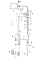
図1は、本発明の一実施形態としての医療装置10の構成を概略的に示す説明図である。医療装置10は、医療機関において利用されるもので、患部に対して液体を噴射することによって、患部を切開または切除する機能を有する。医療装置10は、ハンドピース20と、液体供給部50と、制御部80とを備える。
Next, an embodiment of the present invention will be described.
A. overall structure:
FIG. 1 is an explanatory diagram schematically showing the configuration of a
液体供給部50は、ハンドピース20に液体を供給するためのユニットであり、給水バッグ51と、スパイク針52と、第1〜第5コネクター53a〜53eと、内部に流路が形成された第1〜第4給水チューブ54a〜54dと、ポンプチューブ55と、閉塞検出機構56と、フィルター57とを備える。
The
給水バッグ51は、透明な合成樹脂製であり、内部に液体(具体的には生理食塩水)が充填されている。スパイク針52は、第1コネクター53aを介して、第1給水チューブ54aに接続されている。給水バッグ51にスパイク針52が刺されると、給水バッグ51に充填された液体が第1給水チューブ54aに供給可能な状態になる。液体は、生理食塩水の代わりに、例えば純水や薬液など、生体組織に噴射されても有害でない他の液体であってもよい。
The
第1給水チューブ54aは、第2コネクター53bを介して、チューブポンプ60に接続されている。チューブポンプ60は、第3コネクター53cを介して、第2給水チューブ54bに接続されている。
The first
チューブポンプ60は、ポンプチューブ55内の液体を、第1給水チューブ54a側から、第2給水チューブ54b側に送り出す。チューブポンプ60は、制御部80からポンプ用ケーブル91を介して受信した駆動信号によって駆動される。チューブポンプ60の詳しい構成については、後述する。
The
閉塞検出機構56は、第2給水チューブ54b内の圧力を測定することで、第2〜第4給水チューブ54b〜54d内の閉塞を検出する。
The
第2給水チューブ54bは、第4コネクター53dを介して、第3給水チューブ54cに接続されている。第3給水チューブ54cにはフィルター57が接続されている。フィルター57は、液体に含まれる異物を捕集する。
The second
第3給水チューブ54cは、第5コネクター53eを介して、第4給水チューブ54dに接続されている。第4給水チューブ54dは、ハンドピース20に接続されている。第1〜第4給水チューブ54a〜54dは、ポリ塩化ビニルからなるチューブであり、弾性を有する。なお、第1〜第4給水チューブ54a〜54dは、シリコンや、熱可塑性エラストマーからなるようにしてもよい。
The third
ハンドピース20は、術者が手に持って操作する器具であり、液体噴射管22と、脈動発生部24と、筐体26とを備えた液体噴射装置である。脈動発生部24には、液体供給部50から第4給水チューブ54dを介して液体が供給される。脈動発生部24は、制御部80からアクチュエーター用ケーブル92を介して駆動電圧が印加されると、供給された液体に対して脈動を付与する。脈動が付与された液体は、液体噴射管22の先端の開口部22aから高速噴射される。術者は、ハンドピース20から噴射される脈動が付与された液体を患者の患部である生体組織に当てることによって、例えば患部の切開または切除等の治療を行なう。以下では、脈動が付与された液体を、脈流またはパルス流とも呼ぶ。脈動が付与された液体とは、流量または流速が変動を伴った状態の液体であることを意味する。ここで言う変動は、流量または流速が0になる停止と噴射を繰り返す間欠噴射を含むが、液体の流量または流速が変動していればよいため、必ずしも間欠噴射である必要はない。
The
本実施形態では、脈動発生部24は、圧電素子とダイアフラムとを備えた周知のものである。制御部80から印加される駆動電圧によって圧電素子を動作させて、ダイアフラムによって区画された液体室の容積を増減させることによって、液体室内の液体の圧力を変化させ、液体に脈動を付与する。
In the present embodiment, the
制御部80は、医療装置10の全体の動作を制御する装置であり、術者が足で操作するフットスイッチ94が接続されている。制御部80は、特に、チューブポンプ60と、脈動発生部24とを制御する。具体的には、制御部80は、フットスイッチ94が踏まれている間、ポンプ用ケーブル91とアクチュエーター用ケーブル92とを介して駆動信号を送信する。ポンプ用ケーブル91を介して送信された駆動信号は、チューブポンプ60を駆動させる。チューブポンプ60が駆動すると、ハンドピース20への液体の供給が行われる。アクチュエーター用ケーブル92を介して送信された駆動信号は、脈動発生部24を駆動させる。脈動発生部24が駆動すると、液体に脈動が付与される。よって、術者がフットスイッチ94を踏んでいる間はパルス流が噴射され、術者がフットスイッチ94を踏んでいない間はパルス流の噴射が停止する。
The
制御部80には、使用者が液体の噴射条件を設定するための噴射条件設定部96が接続されている。噴射条件設定部96は、流量設定ダイヤル97と、印加電圧設定ダイヤル98とを備える。
The
流量設定ダイヤル97は、液体供給部50がハンドピース20へ供給する液体の流量Q(ml/min)を術者(術者以外の使用者でも可)が設定するためのダイヤル式操作部である。印加電圧設定ダイヤル98は、脈動発生部24に送信する駆動信号の印加電圧E(V)を術者(術者以外の使用者でも可)が設定するためのダイヤル式操作部である。
The flow
使用者は、流量Qの値および印加電圧Eの値の組み合わせ方を調整することによって、ハンドピース20から噴射させる液体の吐出圧、流量、液滴形状等、ハンドピース20から噴射させる液体の種々の噴射条件を設定することができる。なお、噴射条件設定部96は、流量設定ダイヤル97、印加電圧設定ダイヤル98に限らず、他の操作部を備えるとしてもよい。例えば、印加電圧の周波数を使用者が設定するための周波数設定部や、駆動信号の波形を使用者が設定するための波形設定部など、種々の噴射条件を設定するための操作部を噴射条件設定部96が備えるものとしてもよい。
The user adjusts the combination of the value of the flow rate Q and the value of the applied voltage E to adjust various combinations of the liquid ejected from the
制御部80には、テーブルデータTBLが記憶されている。テーブルデータTBLについては、後ほど詳述する。
The
B.チューブポンプの構成:
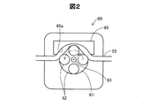
図2は、チューブポンプ60の構造を概念的に示す説明図である。図示するように、チューブポンプ60は、ローラー(押圧部材)62を備えるローター61と、ステーター(案内部材)65と、を備える。
B. Tube pump configuration:
FIG. 2 is an explanatory diagram conceptually showing the structure of the
ステーター65は、円弧状の窪み65aを有する形状である。この窪み65aの壁面に沿って、図1で説明したポンプチューブ55が配置されている。ポンプチューブ(以下、単に「チューブ」とも呼ぶ)55は、シリコンや、フッ素ゴム、弾性樹脂などからなり、弾性を有する。
The
ローター61の外周には、等間隔をあけて4個のローラー62が配置されている。図示しない駆動モーターによって、ローター61は回転軸63を中心として回転される。この駆動モーターが、ポンプ用ケーブル91(図1)を介して受信した駆動信号によって駆動される。各ローラー62は、遊動輪である。各ローラー62がチューブ55を押し付けるように、ステーター65に対するローター61の位置が定められている。ローター61がR方向に回転することで、各ローラー62の位置も回転移動する。これによって、チューブ55は、各ローラー62で押し潰されながら順次しごかれる。この結果、チューブ55内の液体が搬送される。なお、ローラー62の数は4つに限る必要はなく、3つ、2つ、1つ、5つ等、他の数(1または複数)とすることができる。
Four
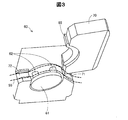
図3は、開閉部70を開いた状態のチューブポンプ60の斜視図である。図示するように、開閉部70にステーター65が備えられている。開閉部70を開いた状態で、チューブ55を、イン側の装填溝71からローラー62を経てアウト側の装填溝72まで掛け渡すことによって、チューブ55はチューブポンプ60へ装填される。
FIG. 3 is a perspective view of the
図4は、開閉部70の内部構成を示す破断断面図である。図示するように、開閉部70には、ステーター65を窪み65a側が突出する状態で収納する収納部73が形成されている。
FIG. 4 is a cutaway sectional view showing the internal configuration of the opening / closing
収納部73の内部には、押圧用モーター75と、連結部材76と、押さえ部材77と、2本のバネ78,79とが設けられている。連結部材76は、押圧用モーター75のネジ軸75aと係合することによって、ネジ軸75aの回転をY方向への直線運動に換えるボールネジ構造を構成している。連結部材76の下方(Y方向の+側)には、押さえ部材77が連結されている。押さえ部材77は、ステーター65の窪み65aとは反対側(Y方向の−側)の面(後方面と呼ぶ)65bに対して、間隙をあけて並列されている。この間隙に、2本のバネ78,79が配設されている。各バネ78,79は、いわゆるコイルバネである。
Inside the
初期状態では、押さえ部材77とステーター65の後方面65bとの間は、所定の距離となっている。所定の距離は、各バネ78,79の長さに応じた大きさとなっており、初期状態における各バネ78,79の付勢力は所定の値P0となる。押圧用モーター75を正回転すると、連結部材76は押さえ部材77をY方向の+側に移動し、各バネ78,79の付勢力を値P0より大きくすることができる。この結果、ステーター65をチューブ55の側に付勢する付勢力(押圧する押圧力とも言える)が増大する。この付勢力の増大分は、押圧用モーター75の正回転の回転量に比例する。押圧用モーター75は、制御部80(図1)から付勢力調整用ケーブル99(図1)を介して受信した駆動信号によって駆動される。
In an initial state, a predetermined distance is provided between the pressing
本実施形態においては、2本のバネ78,79が、本発明の一形態における「付勢部材」の下位概念に相当する。押圧用モーター75、連結部材76、および押さえ部材77が、本発明の一形態における「付勢力調整部」の下位概念に相当する。図1の制御部80は、押圧用モーター75を駆動する駆動信号を制御する付勢力調整制御処理を実行する。この付勢力調整制御処理について、次に説明する。
In the present embodiment, the two
C.付勢力調整制御処理の構成:
図5は、付勢力調整制御処理を示すフローチャートである。付勢力調整制御処理は、医療装置10の電源(図示せず)がオンされた後に、流量設定ダイヤル97が使用者によって操作されたタイミングで実行開始される。
C. Configuration of urging force adjustment control processing:
FIG. 5 is a flowchart showing the urging force adjustment control process. The urging force adjustment control process is started when the flow
処理が開始されると、制御部80は、流量設定ダイヤル97が操作されること、噴射条件設定部96によって設定された液体の流量Qを取得する(ステップS110)。次いで、制御部80は、取得された流量Qに基づいて、押圧用モーター75の回転量VRを算出する(ステップS120)。この算出は、制御部80に記憶されたテーブルデータTBL(図1)を用いて行う。
When the process is started, the
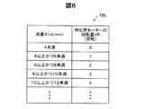
図6は、テーブルデータTBLを示す説明図である。図示するように、テーブルデータTBLは、流量Qと、押圧用モーター75の回転量VRとの2つの項目を有し、流量Qに対応する押圧用モーター75の回転量VRを示す表形式のデータである。
FIG. 6 is an explanatory diagram showing the table data TBL. As shown in the figure, the table data TBL has two items of a flow rate Q and a rotation amount VR of the
流量Qと回転量VRとの関係は、次のようにして求められる。まず、流量Qに応じて必要となるバネ78,79の付勢力を、実験的にあるいはシミュレーションによって求める。次いで、求めた付勢力を得るのに必要な押さえ部材77(図4)のY方向の変位を、実験的にあるいはシミュレーションによって求める。その後、求めた押さえ部材77の変位を得るのに必要な押圧用モーター75の回転量VRを、実験的にあるいはシミュレーションによって求める。こうして求めた流量Qに対応する回転量VRをテーブルデータTBLに記録する。
The relationship between the flow rate Q and the rotation amount VR is obtained as follows. First, the urging force of the
図6に示すように、例えば、使用者によって設定された流量Qが4ml/min未満の場合には、押圧用モーター75の回転量VRは0回転となる(回転しない)。流量Qが4ml/min以上かつ6ml/min未満の場合には回転量VRは1回転となり、流量Qが6ml/min以上かつ8ml/min未満の場合には回転量VRは2回転となり、流量Qが8ml/min以上かつ10ml/min未満の場合には回転量VRは3回転となり、流量Qが10ml/min以上かつ12ml/min未満の場合には回転量VRは4回転となる。このように、テーブルデータTBLは、流量Qが大きくなるに連れて、回転量VRが大きくなるように決められている。
As shown in FIG. 6, for example, when the flow rate Q set by the user is less than 4 ml / min, the rotation amount VR of the
図5のステップS120では、制御部80は、テーブルデータTBLにステップS110によって取得された液体の流量Qを投入して、流量Qに対応する回転量VRをテーブルデータTBLから取得する。続いて、制御部80は、ステップS120によって求められた回転量VRに基づいて押圧用モーター75を駆動する。その後、「リターン」に抜けて、付勢力調整制御処理を終了する。
In step S120 of FIG. 5, the
以上のように構成された付勢力調整制御処理によれば、チューブポンプ60において、ステーター65をチューブ55の側に付勢するバネ78,79の付勢力を、噴射条件設定部96によって設定された液体の流量Qに応じて調整することができる。前述したように、テーブルデータTBLは、液体の流量Qが大きくなるに連れて、回転量VRが大きくなるように決められていることから、設定された流量Qが大きいほど、押さえ部材77とステーター65との間の距離が狭くなり、バネ78,79の付勢力を大きくすることができる。換言すれば、液体の流量Qが小さくなるほど、押さえ部材77とステーター65との間の距離が広くなり、バネ78,79の付勢力を小さくすることができる。
According to the urging force adjustment control process configured as described above, in the
D.実施形態の効果:
以上のように構成された本実施形態の医療装置10によれば、チューブポンプ60において、ステーター65をチューブ55の側に付勢するバネ78,79の付勢力が、押圧用モーター75、連結部材76、および押さえ部材77によって調整されるため、チューブポンプ60よりも下流の流路内やハンドピース20の液体噴射管22が詰まった場合の、液体噴射管22内の最大到達圧力を適切に管理できる。管理が可能なのは、バネ78,79の付勢力と最大到達圧力との間に相関があるためである。この相関は、本発明の発明者によって得られた新たな知見であり、次の実験からも証明される。
D. Effects of the embodiment:
According to the
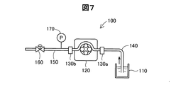
図7は、実験例の液体供給装置を示す説明図である。実験例の液体供給装置100は、液体容器110と、チューブポンプ120と、第1および第2コネクター130a,130bと、給水流路140と、排水流路150と、開閉バルブ160と、圧力計170とを備える。チューブポンプ120によって、吸水流路140を介して液体容器110から吸引した液体を、排水流路150を介して外部に排水する。排水流路150のチューブポンプ120とは反対側の端部には開閉バルブ160が設けられており、排水流路150の途中には圧力計170が接続されている。
FIG. 7 is an explanatory view showing a liquid supply apparatus of an experimental example. The
チューブポンプ120は、バネによってステーターをチューブの側に付勢することのできるタイプのものであるが、バネの付勢力は、一定で可変できない。すなわち、チューブポンプ120は、バネの付勢力を調整する付勢力調整部を有しない構成である。この実験例では、チューブポンプ120を分解して、バネ自体を、長さ(自然長の意味であり、以下、「ばね長」と呼ぶ)の相違するバネに交換を行った。具体的には、バネ長が12.4mm、13.5mm、15mmの3種類のバネに交換した。これらのバネは、バネ長が相違するだけで、バネ長以外のバネ特性を決める寸法や材料は同一である。バネが取り付けられる間隙は一定であることから、バネ長が長いほど、バネの付勢力は大きくなる。すなわち、3種類のバネの中では、バネ長が12.4mmのバネが最も付勢力が小さく、バネ長が15mmのバネが最も付勢力が大きい。バネ長が13.5mmのバネは中間の付勢力である。
The
上記12.4mm、13.5mm、15mmの各バネを取り付けたケース毎に実験を行った。実験の詳細は、開閉バルブ160を開いてチューブポンプ120を作動させた状態から、開閉バルブ160を全閉状態とし、排水流路150を閉塞させる。そして、閉塞開始からの排水流路150内の圧力変化を、圧力計170によって測定する。
An experiment was conducted for each case to which the above 12.4 mm, 13.5 mm, and 15 mm springs were attached. For details of the experiment, the open /
図8は、各ケースにおける圧力変化を示すグラフである。グラフから判るように、いずれのバネも、閉塞開始からの圧力上昇の速度はほとんど変わらない。閉塞開始からの圧力が上昇して一定の圧力(最大到達圧力)に落ち着くが、この最大到達圧力は、バネの種類によって異なる。バネ長が12.4mmのバネが、最も最大到達圧力が低く、バネ長が15mmのバネが、最も最大到達圧力が高い。バネ長が13.5mmのバネは中間の最大到達圧力である。 FIG. 8 is a graph showing the pressure change in each case. As can be seen from the graph, the rate of pressure increase from the start of occlusion hardly changes in any spring. The pressure from the start of closing increases and settles to a constant pressure (maximum ultimate pressure). This maximum ultimate pressure varies depending on the type of spring. A spring having a spring length of 12.4 mm has the lowest maximum ultimate pressure, and a spring having a spring length of 15 mm has the highest maximum ultimate pressure. A spring having a spring length of 13.5 mm has an intermediate maximum ultimate pressure.
図9は、各ケースにおけるバネの長さと最大到達圧力との関係を示すグラフである。このグラフからも解るように、バネ長が短いほど、最大到達圧力は低くなる。これらのことから、バネの付勢力が小さいほど、最大到達圧力が低くなるという知見が得られた。 FIG. 9 is a graph showing the relationship between the spring length and the maximum ultimate pressure in each case. As can be seen from this graph, the shorter the spring length, the lower the maximum ultimate pressure. From these facts, it was found that the smaller the urging force of the spring, the lower the maximum ultimate pressure.
一般的なチューブポンプの場合、図8からも判るように、閉塞開始後からの排水流路内の圧力上昇は急峻である。このため、医療用の液体噴射装置に液体を供給する液体供給装置に一般的なチューブポンプを採用した場合に、次のような不具合が発生した。液体供給装置の液体噴射管内に異物が混入すると、液体噴射管が詰まって、液体を噴射できなくなるが、この詰まった状態からなんらかの要因で閉塞物が除去される可能性がある。閉塞物が除去されると、除去された瞬間に一時的に非常に強い噴射が起こる虞があった。 In the case of a general tube pump, as can be seen from FIG. 8, the pressure rise in the drainage flow channel after the start of the blockage is steep. For this reason, when a general tube pump is adopted as a liquid supply apparatus that supplies liquid to a medical liquid ejecting apparatus, the following problems occur. If foreign matter is mixed in the liquid jet tube of the liquid supply device, the liquid jet tube is clogged and it becomes impossible to eject the liquid. However, there is a possibility that the obstruction is removed from the clogged state for some reason. When the obstruction is removed, there is a possibility that a very strong jet may temporarily occur at the moment of removal.
本実施形態の医療装置10では、噴射条件設定部96による液体の流量Qの設定を低くすることで、閉塞時における最大到達圧力を低くすることができる。一般に、低侵襲性が重要とされる部位(例えば、脳)においては、液体の流量Qの設定を低くするが、こうした場合に、医療装置10では、最大到達圧力が低くなることから、上述したような、閉塞物が除去された瞬間に強い噴射が起こる不具合を防止できる。
In the
E.変形例:
この発明は前記実施形態およびその変形例に限られるものではなく、その要旨を逸脱しない範囲において種々の態様において実施することが可能であり、例えば、次のような変形も可能である。
E. Variations:
The present invention is not limited to the above-described embodiment and its modifications, and can be carried out in various modes without departing from the gist thereof. For example, the following modifications are possible.
・変形例1:
前記実施形態では、付勢部材として、コイルバネを用いていたが、これに換えて、板バネ、空気バネ等の他の種類のばねを用いてもよい。また、バネは、金属製、樹脂製のいずれであってもよい。さらに、付勢部材として、バネ形状を有しない素材そのものが弾性力を有する弾性樹脂、ゴム材等を用いてもよい。
・ Modification 1:
In the embodiment, the coil spring is used as the biasing member, but other types of springs such as a plate spring and an air spring may be used instead. Further, the spring may be made of metal or resin. Further, as the biasing member, an elastic resin, a rubber material, or the like in which the material itself having no spring shape has an elastic force may be used.
・変形例2:
前記実施形態では、付勢力調整部を、押圧用モーター75、連結部材76、および押さえ部材77によって構成していたが、付勢力調整部はこの構成に限る必要はない。例えば、他の構成の動力伝達機構を用いて、モーターの駆動力を付勢部材に伝達する構成としてもよい。また、モーターを用いることなく、人力によって付勢部材の付勢力を調整する構成としてもよい。例えば、使用者によって操作されるスライドレバーによって押さえ部材が移動する構成とすることができる。
In the above-described embodiment, the urging force adjusting unit is configured by the
・変形例3:
前記実施形態では、噴射条件設定部96によって設定される流量Qに基づいて付勢力調整部を制御する構成としたが、これに換えて、付勢力調整用の専用ボタンからの調整指示に基づいて、付勢力調整部を制御する構成としてもよい。さらには、設定される流量や、調整指示以外の他のパラメータに基づいて付勢力調整部を制御する構成としてもよい。例えば、付勢部材を形状記憶合金製のばねとし、周囲の温度に基づいてバネの付勢力が変わる構成とすることができる。
・ Modification 3:
In the above embodiment, the urging force adjusting unit is controlled based on the flow rate Q set by the injection
・変形例4:
前記実施形態では、ハンドピース20に備えられる脈動発生部24を、圧電素子とダイアフラムとからなる容積調整手段を備える構成としたが、これに換えて、圧電素子以外の駆動源によって液体室の容積を調整する構成としてもよい。また、液体室内の液体内に気泡を発生させる気泡発生部を設けて、液体室内の液体の圧力を変化させる構成としてもよい。気泡発生部は、光メーザー、レーザー光、抵抗体ヒーター、セラミックヒーター、マイクロ波を照射する構成などでもよい。
-Modification 4:
In the above-described embodiment, the
・変形例5:
本発明の医療装置の使用目的は、人間の治療でなくてもよい。例えば、人間を除く動物を治療してもよいし、研究や教育のために人体組織を切除してもよい。また、本発明のチューブポンプは、噴射した液体によって汚れを除去する洗浄装置に利用されてもよいし、噴射した液体によって線などを描く描画装置に利用されてもよい。
Modification 5:
The purpose of use of the medical device of the present invention may not be human therapy. For example, animals other than humans may be treated, or human tissue may be excised for research or education. Moreover, the tube pump of the present invention may be used in a cleaning device that removes dirt with the ejected liquid, or may be used in a drawing device that draws a line or the like with the ejected liquid.
・変形例6:
前記実施形態では、押圧用モーター75、連結部材76、および押さえ部材77によって、バネ78,79の付勢力が調整される構成とした。この構成によれば、チューブが弾性材料によって形成されていることから、ステーター65の位置がローラー62の回転軌道に対して近づいたり遠ざかったりすることになる。これに対して、変形例として、押圧用モーター75も連結部材76も押さえ部材77も省いて、ステーターの窪みの壁面とローターの軌道との間の距離を調整する構成としてもよい。前記距離を調整できれば、ステーターの側を移動してもよいし、ローラーを有するローターを移動してもよい。この移動は、モーターの動力によって移動してもよいし、人力によって移動してもよい。
Modification 6:
In the embodiment, the urging force of the
・変形例7:
前記実施形態では、バネ78,79の付勢力を調整することによって、ステーター65をチューブ55の側に付勢する付勢力が調整される構成としたが、これに換えて、ローラー62が配置されたステーター65全体を、チューブ55がステーター65側に付勢する方向に付勢部材によって付勢する構成とし、その付勢部材の付勢力を調整する構成としてもよい。この構成によっても、第1実施形態と同様に、液体噴射装置内が詰まった場合における液体噴射装置内の最大到達圧力を適切に管理できる。
Modification 7:
In the above embodiment, the urging force for urging the
本発明は、上述の実施形態や実施例、変形例に限られるものではなく、その趣旨を逸脱しない範囲において種々の構成で実現できる。例えば、発明の概要の欄に記載した各形態中の技術的特徴に対応する実施形態、実施例、変形例中の技術的特徴は、上述の課題の一部または全部を解決するために、あるいは、上述の効果の一部または全部を達成するために、適宜、差し替えや組み合わせを行うことが可能である。また、その技術的特徴が本明細書中に必須なものとして説明されていなければ、適宜、削除することが可能である。 The present invention is not limited to the above-described embodiments, examples, and modifications, and can be realized with various configurations without departing from the spirit of the present invention. For example, the technical features in the embodiments, examples, and modifications corresponding to the technical features in each embodiment described in the summary section of the invention are to solve some or all of the above-described problems, or In order to achieve part or all of the above-described effects, replacement or combination can be performed as appropriate. Further, if the technical feature is not described as essential in the present specification, it can be deleted as appropriate.
10…医療装置
20…ハンドピース
22…液体噴射管
22a…開口部
24…脈動発生部
26…筐体
50…液体供給部
51…給水バッグ
52…スパイク針
53a〜53e…第1〜第5コネクター
54a〜54d…第1〜第4給水チューブ
55…ポンプチューブ(チューブ)
56…閉塞検出機構
57…フィルター
60…チューブポンプ
61…ローター
62…ローラー
63…回転軸
65…ステーター
70…開閉部
71,72…装填溝
73…収納部
75…押圧用モーター
75a…ネジ軸
76…連結部材
77…押さえ部材
78,79…バネ
80…制御部
91…ポンプ用ケーブル
92…アクチュエーター用ケーブル
94…フットスイッチ
96…噴射条件設定部
97…流量設定ダイヤル
98…印加電圧設定ダイヤル
99…付勢力調整用ケーブル
TBL…テーブルデータ
Q…流量
VR…回転量
DESCRIPTION OF
56 ...
Claims (5)
前記案内部材を前記チューブの側に付勢する付勢部材と、
前記付勢部材の付勢力を調整する付勢力調整部と、
を備える、チューブポンプ。 A tube pump that conveys the liquid in the tube by moving the pressing member while crushing the tube arranged along the guide member with the pressing member,
A biasing member that biases the guide member toward the tube;
An urging force adjusting unit for adjusting the urging force of the urging member;
A tube pump comprising:
案内部材に沿って配置されたチューブを押圧部材で押し潰しつつ前記押圧部材を移動させることによって、前記チューブ内の液体を搬送するチューブポンプと、
前記チューブポンプから液体の供給を受ける液体噴射装置と、
を備え、
前記チューブポンプは、
前記案内部材を前記チューブの側に付勢する付勢部材と、
前記付勢部材の付勢力を調整する付勢力調整部と、
を備える、医療装置。 A medical device,
A tube pump for transporting the liquid in the tube by moving the pressing member while crushing the tube arranged along the guide member with the pressing member;
A liquid ejecting apparatus that receives a supply of liquid from the tube pump;
With
The tube pump is
A biasing member that biases the guide member toward the tube;
An urging force adjusting unit for adjusting the urging force of the urging member;
A medical device comprising:
前記液体噴射装置へ供給する液体の流量を設定する流量設定部と、
前記設定された流量に基づいて前記付勢力調整部を制御する制御部と、
を備える医療装置。 The medical device according to claim 3,
A flow rate setting unit for setting a flow rate of the liquid supplied to the liquid ejecting apparatus;
A control unit for controlling the biasing force adjusting unit based on the set flow rate;
A medical device comprising:
前記制御部は、前記設定された流量が小さいほど、前記付勢力を小さくする、医療装置。 The medical device according to claim 4,
The said control part is a medical device which makes the said energizing force small, so that the said set flow volume is small.
Priority Applications (1)
| Application Number | Priority Date | Filing Date | Title |
|---|---|---|---|
| JP2015043066A JP2016160901A (en) | 2015-03-05 | 2015-03-05 | Tube pump and medical device |
Applications Claiming Priority (1)
| Application Number | Priority Date | Filing Date | Title |
|---|---|---|---|
| JP2015043066A JP2016160901A (en) | 2015-03-05 | 2015-03-05 | Tube pump and medical device |
Publications (1)
| Publication Number | Publication Date |
|---|---|
| JP2016160901A true JP2016160901A (en) | 2016-09-05 |
Family
ID=56844430
Family Applications (1)
| Application Number | Title | Priority Date | Filing Date |
|---|---|---|---|
| JP2015043066A Pending JP2016160901A (en) | 2015-03-05 | 2015-03-05 | Tube pump and medical device |
Country Status (1)
| Country | Link |
|---|---|
| JP (1) | JP2016160901A (en) |
Cited By (3)
| Publication number | Priority date | Publication date | Assignee | Title |
|---|---|---|---|---|
| CN108030483A (en) * | 2017-12-06 | 2018-05-15 | 深圳市星河泉新材料有限公司五金配件分厂 | A kind of pressure structure, blood pressure detecting module and blood pressure intelligent detection equipment |
| CN113574276A (en) * | 2019-03-15 | 2021-10-29 | 纳科斯达格医药股份有限公司 | Peristaltic pump |
| WO2023286965A1 (en) * | 2021-07-14 | 2023-01-19 | 주식회사 테크로스 | Transfer pump for fixed amount of fluid |
-
2015
- 2015-03-05 JP JP2015043066A patent/JP2016160901A/en active Pending
Cited By (4)
| Publication number | Priority date | Publication date | Assignee | Title |
|---|---|---|---|---|
| CN108030483A (en) * | 2017-12-06 | 2018-05-15 | 深圳市星河泉新材料有限公司五金配件分厂 | A kind of pressure structure, blood pressure detecting module and blood pressure intelligent detection equipment |
| CN108030483B (en) * | 2017-12-06 | 2023-12-29 | 深圳市星河泉新材料有限公司 | Pressurization structure, blood pressure detection module and blood pressure intelligent detection equipment |
| CN113574276A (en) * | 2019-03-15 | 2021-10-29 | 纳科斯达格医药股份有限公司 | Peristaltic pump |
| WO2023286965A1 (en) * | 2021-07-14 | 2023-01-19 | 주식회사 테크로스 | Transfer pump for fixed amount of fluid |
Similar Documents
| Publication | Publication Date | Title |
|---|---|---|
| AU2005229673B2 (en) | Fluid cutting device and method of use | |
| JP6921878B2 (en) | A device for distributing liquid to the environment of the eye | |
| EP2821018B1 (en) | Fluid injection device | |
| JP2004507321A (en) | Injection control system | |
| KR20100080823A (en) | Dispensing method and system of a capillary aerosol generator | |
| JP2016160901A (en) | Tube pump and medical device | |
| US20140296892A1 (en) | Fluid ejection device and medical apparatus | |
| US10143811B2 (en) | Fluid management of adipose tissue | |
| US20170014149A1 (en) | Liquid Ejection Device and Surgical Apparatus | |
| JP2010075589A (en) | Fluid injection device, method for controlling the same, and operation device | |
| JP2015156919A (en) | Fluid injection device and medical instrument | |
| JP6382858B2 (en) | Oral care device using jet fluid flow | |
| WO2016174873A1 (en) | Liquid supply device and medical device, and method for diagnosing failure in liquid supply device | |
| JP2010059939A (en) | Fluid injection device, method of controlling fluid injection device, and surgical device | |
| JP2015058240A (en) | Medical device system and liquid supply device | |
| JP2010077949A (en) | Fluid injection device, method for molding pipe member, fluid injection unit, and surgical apparatus | |
| JP2016176362A (en) | Tube pump, tube, medical device, and liquid supply method | |
| JP2016163620A (en) | Control device, medical device, and control method | |
| US10130740B2 (en) | Pressure control during processing of adipose tissue | |
| JP5703742B2 (en) | Fluid ejecting apparatus and medical device | |
| US20140296893A1 (en) | Liquid ejection device and medical apparatus | |
| JP2017101598A (en) | Liquid injection device, program, and control device | |
| WO2016006179A1 (en) | Liquid injection unit, liquid injection device, endoscopic device, and medical device | |
| US20230255824A1 (en) | Tip unclogging using controlled aspiration reflux | |
| CN117255701A (en) | Intelligent irrigation and aspiration system and method |