JP2004507321A - Injection control system - Google Patents
Injection control system Download PDFInfo
- Publication number
- JP2004507321A JP2004507321A JP2002522809A JP2002522809A JP2004507321A JP 2004507321 A JP2004507321 A JP 2004507321A JP 2002522809 A JP2002522809 A JP 2002522809A JP 2002522809 A JP2002522809 A JP 2002522809A JP 2004507321 A JP2004507321 A JP 2004507321A
- Authority
- JP
- Japan
- Prior art keywords
- infusate
- control module
- supply
- source
- pressure
- Prior art date
- Legal status (The legal status is an assumption and is not a legal conclusion. Google has not performed a legal analysis and makes no representation as to the accuracy of the status listed.)
- Pending
Links
Images
Classifications
-
- A—HUMAN NECESSITIES
- A61—MEDICAL OR VETERINARY SCIENCE; HYGIENE
- A61F—FILTERS IMPLANTABLE INTO BLOOD VESSELS; PROSTHESES; DEVICES PROVIDING PATENCY TO, OR PREVENTING COLLAPSING OF, TUBULAR STRUCTURES OF THE BODY, e.g. STENTS; ORTHOPAEDIC, NURSING OR CONTRACEPTIVE DEVICES; FOMENTATION; TREATMENT OR PROTECTION OF EYES OR EARS; BANDAGES, DRESSINGS OR ABSORBENT PADS; FIRST-AID KITS
- A61F9/00—Methods or devices for treatment of the eyes; Devices for putting-in contact lenses; Devices to correct squinting; Apparatus to guide the blind; Protective devices for the eyes, carried on the body or in the hand
- A61F9/007—Methods or devices for eye surgery
- A61F9/00736—Instruments for removal of intra-ocular material or intra-ocular injection, e.g. cataract instruments
-
- A—HUMAN NECESSITIES
- A61—MEDICAL OR VETERINARY SCIENCE; HYGIENE
- A61M—DEVICES FOR INTRODUCING MEDIA INTO, OR ONTO, THE BODY; DEVICES FOR TRANSDUCING BODY MEDIA OR FOR TAKING MEDIA FROM THE BODY; DEVICES FOR PRODUCING OR ENDING SLEEP OR STUPOR
- A61M1/00—Suction or pumping devices for medical purposes; Devices for carrying-off, for treatment of, or for carrying-over, body-liquids; Drainage systems
- A61M1/71—Suction drainage systems
- A61M1/77—Suction-irrigation systems
-
- A—HUMAN NECESSITIES
- A61—MEDICAL OR VETERINARY SCIENCE; HYGIENE
- A61B—DIAGNOSIS; SURGERY; IDENTIFICATION
- A61B17/00—Surgical instruments, devices or methods, e.g. tourniquets
- A61B2017/00017—Electrical control of surgical instruments
- A61B2017/00022—Sensing or detecting at the treatment site
- A61B2017/00084—Temperature
-
- A—HUMAN NECESSITIES
- A61—MEDICAL OR VETERINARY SCIENCE; HYGIENE
- A61B—DIAGNOSIS; SURGERY; IDENTIFICATION
- A61B90/00—Instruments, implements or accessories specially adapted for surgery or diagnosis and not covered by any of the groups A61B1/00 - A61B50/00, e.g. for luxation treatment or for protecting wound edges
- A61B90/03—Automatic limiting or abutting means, e.g. for safety
- A61B2090/032—Automatic limiting or abutting means, e.g. for safety pressure limiting, e.g. hydrostatic
-
- A—HUMAN NECESSITIES
- A61—MEDICAL OR VETERINARY SCIENCE; HYGIENE
- A61M—DEVICES FOR INTRODUCING MEDIA INTO, OR ONTO, THE BODY; DEVICES FOR TRANSDUCING BODY MEDIA OR FOR TAKING MEDIA FROM THE BODY; DEVICES FOR PRODUCING OR ENDING SLEEP OR STUPOR
- A61M2205/00—General characteristics of the apparatus
- A61M2205/33—Controlling, regulating or measuring
- A61M2205/3331—Pressure; Flow
- A61M2205/3344—Measuring or controlling pressure at the body treatment site
-
- A—HUMAN NECESSITIES
- A61—MEDICAL OR VETERINARY SCIENCE; HYGIENE
- A61M—DEVICES FOR INTRODUCING MEDIA INTO, OR ONTO, THE BODY; DEVICES FOR TRANSDUCING BODY MEDIA OR FOR TAKING MEDIA FROM THE BODY; DEVICES FOR PRODUCING OR ENDING SLEEP OR STUPOR
- A61M2205/00—General characteristics of the apparatus
- A61M2205/33—Controlling, regulating or measuring
- A61M2205/3368—Temperature
Landscapes
- Health & Medical Sciences (AREA)
- Heart & Thoracic Surgery (AREA)
- Life Sciences & Earth Sciences (AREA)
- Animal Behavior & Ethology (AREA)
- Engineering & Computer Science (AREA)
- Biomedical Technology (AREA)
- Ophthalmology & Optometry (AREA)
- Vascular Medicine (AREA)
- Veterinary Medicine (AREA)
- Public Health (AREA)
- General Health & Medical Sciences (AREA)
- Surgery (AREA)
- Nuclear Medicine, Radiotherapy & Molecular Imaging (AREA)
- Pulmonology (AREA)
- Anesthesiology (AREA)
- Hematology (AREA)
- External Artificial Organs (AREA)
- Eye Examination Apparatus (AREA)
Abstract
手術中の眼内圧又は手術中の創傷部位温度を制御する外科用システムの操作方法。A method of operating a surgical system for controlling intraocular pressure during surgery or wound site temperature during surgery.
Description
【0001】
本発明の背景
本発明は、広くは白内障手術の技術分野、より詳細には水晶体乳化用ハンドピースのための注入制御システムに関する。
【0002】
簡単に言えば、人間の眼は、角膜と呼ばれる透明な外側部分を通して光を伝達することと、水晶体を用いて画像を網膜上に焦点合わせすることとにより、視覚を提供する機能を有する。焦点合わせされた画像の質は、眼の寸法及び形状並びに角膜及び水晶体の透明度を含む多くの要因に依存する。
【0003】
加齢や疾患によって水晶体の透明度が低下すると、網膜に伝達される光が減少するために視力が低下する。眼の水晶体におけるこの欠陥は、医学的には白内障として知られている。この容態に対する認容された治療法は、外科的に、水晶体を除去して、人工の眼内水晶体(IOL)によって機能する水晶体と置換することである。
【0004】
合衆国においては、白内障水晶体の大多数は、水晶体乳化法と呼ばれる外科技術によって除去される。この処置をする間は、水晶体乳化用の薄い切断チップが、疾患のある水晶体内に挿入されて超音波振動する。振動する切断チップは、水晶体を眼の外へ吸引できるようにするために、水晶体を流動化又は乳化させる。疾患のある水晶体は、除去された後は、人口水晶体に置換される。
【0005】
眼病処置に適した典型的な超音波外科装置は、超音波振動するハンドピース、それに取付けられる切断チップ並びに洗浄用のスリーブ及び電子制御装置を有する。ハンドピース組立品は、ケーブル及びフレキシブルなラインによって制御装置に取付けられる。制御装置は、ケーブルを通じて、取付けられた切断チップにハンドピースによって送られる電力レベルを変化させ、またフレキシブルなラインは、ハンドピース組立品を通して、洗浄液を眼に供給しまた眼から吸引液を抜き出す。
【0006】
ハンドピースの動作部分は、中央に配置された中空の共振する棒(バー)又は角(ホーン)であり、一組の圧電性振動子(piezoelectric crystals)に直接取付けられる。その振動子は、ホーン及び取付けられた切断チップが制御装置に制御されている間及び水晶体乳化を行う間に、ホーン及び切断チップを作動させるために必要な超音波振動を供給する。振動子及びホーンの組立品は、ハンドピースが有する中空の本体又は胴体の内部に、自在取付具により支持される。ハンドピース本体の末端部は、縮径部分又はノーズコーン(nosecone)となっている。ノーズコーンは、洗浄用スリーブを螺着させるための外ねじを有する。同様に、ホーンの穴は、切断チップの外ねじと螺接するための内ねじをその端部に有する。洗浄用スリーブはまた、ノーズコーンの外ねじと螺接する内ねじを備える穴を有する。切断チップは、チップが洗浄用スリーブの開口端部を通り越して予め定めた量だけ突き出るように調節される。超音波ハンドピース及び切断チップは、米国特許3,589,363号、4,223,676号、4,246,902号、4,493,694号、4,515,583号、4,589,415号、4,609,368号、4,869,715号、4,922,902号、4,989,583号、5,154,694号及び5,359,996号に十分に説明されており、それらの全体の内容は本願に関連技術として引用されている。
【0007】
使用中は、切断チップ及び洗浄用スリーブの端部は、角膜、強膜又は他の場所の中にある予め定めた幅の小さな切開部内に挿入される。切断チップは、振動子により作動する超音波ホーンによって、チップの長手方向軸線に沿って洗浄用スリーブ内で超音波振動させられ、そのことによって選択された組織をその場所で乳化させる。切断チップが有する中空の穴は、ホーンの穴と連通して、次にホーンの穴は、ハンドピースから制御装置へ向かう吸引ラインと連通する。制御装置内の減圧又は真空源は、乳化した組織を、切断チップの開口端部、切断チップ及びホーンの穴並びに吸引ラインを通して、眼から抜出し又は吸引し、捕集装置内へ送る。乳化した組織の吸引は、洗浄用スリーブの内表面と切断チップとの間にある小さな環状の間隙を通って外科部位内へ注入される食塩水のフラッシング液すなわち洗浄液によって補助される。
【0008】
乱視を引き起す危険性を低減するために、前眼房内の切開を可能な限り小さく行うことは、好ましい外科技術である。これらの小さな切開は、振動チップに対して洗浄用スリーブをしっかりと締め付ける非常に緊密な創傷になる。洗浄用スリーブと振動チップとの間の摩擦は熱を発生させるが、チップの内側を流れる吸引液の冷却効果によって、チップの過熱及び組織の熱傷を起こす危険性は低減される。チップが組織によって閉塞されているときは、この吸引液の流れは減少又は停止してチップが過熱されることがある。
【0009】
従来技術による装置は、吸引時における真空度の大きな上昇を検出するとともに真空度の上昇による閉塞を予測するセンサーを使用している。この感知された閉塞によって、ハンドピースに与えられる電力の減少並びに洗浄及び吸引流量の増加の少なくとも一方が可能となる。その全体の内容が本願に関連技術として引用されている米国特許5,591,127号、5,700,240号及び5,766,146号(Barwick,Jr.等)を参照のこと。しかし、吸引ライン内の真空度の上昇は、チップ周りの冷却液の流量が遮断されることを必ずしも示さない。最も緊密な切開によってでさえ、創傷と洗浄用スリーブの外側との間から洗浄液がいくらかは漏洩する。この創傷からの漏洩は切開部位をさらに冷却する流れとなるため、吸引時の真空度の上昇を測定することのみでは、角膜に熱傷を起こすためのポテンシャルを必ずしも示さない。従って、ハンドピースに与えられる電力は尚早に中断されることになる。
【0010】
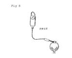
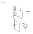
従来技術による装置はまた、外科的な注入圧力及び流量を制御するための、重力による送液方法又は与圧されたガス供給源を使用する。図8に示されるような重力送液注入方法により、液柱の高さに基づく圧力及び流量が得られる。液柱が高くなると、圧力及び流量は増加する。液柱が低くなると、圧力及び流量は低下する。外科医は、注入液の入ったボトルを上げ下げすることによって液柱の高さを調節する。図9に示されるような与圧されたガス供給源は、注入液ボトル内側の圧力を上げ下げすることによって注入圧力を調節する。ボトルは一定の高さに吊下げられ、ガス圧力ポンプがそのボトルに接続される。その全体の内容が本願に関連技術として引用されている米国特許4,813,927号、4,900,301号、5,032,111号及び5,047,009号(Morris等)を参照のこと。重力送液注入方法は、注入液ボトルを上げ下げする必要から生じる圧力の応答速度に限界がある。与圧されたガス供給源は、応答速度は改善されているが、外科手術の準備を複雑にする煩わしい通気チューブ装置を必要とする。いずれの方法も、汚染防止のためにボトル内の空気又はガスを濾過する必要があり、これにより費用と複雑さが増す。
【0011】
故に、注入圧力及び流量を扱うよりよい方法を利用する外科用装置のための注入源が望まれる。
【0012】
本発明の概要
本発明は、種々の注入液圧力センサーを有する外科用注入システムを備えることにより、従来技術を改良したものである。本システムはまた、圧縮可能な注入容器を使用する。注入液圧力センサーにより与えられる情報により、使用者は、手術中の眼内圧及び手術中の創傷部位の温度を予測し制御することができる。
【0013】
従って、本発明の1つの目的は、外科用装置制御システムを提供することである。
【0014】
本発明の他の目的は、洗浄液の圧力を感知できる外科用装置制御システムの操作方法を提供することである。
【0015】
本発明の他の目的は、ハンドピースの操作パラメータをより正確に制御する外科用装置制御システムの操作方法を提供することである。
【0016】
本発明の他の目的は、注入操作パラメータをより正確に制御する外科用装置制御システムの操作方法を提供することである。
【0017】
本発明の他の目的は、吸引操作パラメータをより正確に制御する外科用装置制御システムの操作方法を提供することである。
【0018】
本発明の他の目的は、手術中の眼内圧をより正確に制御する外科用装置制御システムの操作方法を提供することである。
【0019】
本発明の他の目的は、手術中の創傷部位の温度をより正確に制御する外科用装置制御システムの操作方法を提供することである。
【0020】
本発明の他の目的は、注入圧力及び流量のより速くより正確な制御を提供することである。
【0021】
本発明が有するこれら及び他の長所並びに目的は、以下の詳細な説明及び特許請求の範囲から明らかになるであろう。
【0022】
本発明の詳細な説明
図1に示されるように、本発明の第1の実施形態において、ハンドピース12の操作に使用される制御システム10は、制御装置14を有する。制御装置14は、通常は制御モジュール又はCPU16、吸引ポンプ18、ハンドピース電源20、洗浄液流量センサー22及びバルブ24を有する。制御装置14には、テキサス州フォートワースのアルコン・ラボラトリーズ社より入手できるACCURUS登録商標又はLEGACY SERIES TWENTY THOUSAND登録商標外科用システムのような、全ての市販の外科用制御装置が使用可能である。CPU16には、適当なマイクロプロセッサ、マイクロコントローラ、コンピュータ又はデジタル論理コントローラの全てが使用可能である。ポンプ18には、蠕動ポンプ、スクロールポンプ、ダイアフラムポンプ又はベンチュリポンプのような適当な全てのポンプが使用可能である。電源20には、テキサス州フォートワースのアルコン・ラボラトリーズ社より入手できるACCURUS登録商標又はLEGACY SERIES TWENTY THOUSAND登録商標外科用システムに組み込まれているような、適当な全ての超音波励振器が使用可能である。センサー22には、ニューヨーク州イサーケのトランソニック・システムズ社より入手できるモデル番号T101D又はT201Dのような、市販の全ての流量センサーが使用可能である。バルブ24には、ソレノイド作動ピンチバルブのような適当な全てのバルブが使用可能である。注入液供給源26には、市販の全ての洗浄溶液が使用可能である。
【0023】
使用中は、センサー22は、洗浄ライン30、32及び34を介してハンドピース12及び注入液供給源26に接続される。センサー22は、供給源26からハンドピース12へ向かう洗浄液の流量を測定し、この情報をケーブル36を通じてCPU16に与える。洗浄液流量データは、この技術分野ではよく知られたソフトウェア命令を使用して制御装置14の操作パラメータを制御するために、CPU16に使用されることができる。例えば、CPU16は、ケーブル38を通じてバルブ24を開閉して、供給源26からハンドピース12に至る洗浄液量を変えることができる。CPU16はまた、ケーブル40を通じて、電力ケーブル42を通じてハンドピース12に送られる電源20の出力を変えることができる。CPU16はまた、センサー22により与えられるデータを使用して、ポンプ18の動作を変更することができる。ポンプ18は、ライン46を通じてハンドピース12から液体を吸引し、ライン48を通じてその液体を捕集容器28へ送る。
【0024】
図2に示されるように、本発明の第2の実施形態において、ハンドピース112の操作に使用されるための制御システム110は、制御装置114を有する。制御装置114は、通常は制御モジュール又はCPU116、吸引ポンプ118、ハンドピース電源120及びバルブ124を有する。流量センサー122は、ハンドピース112の内部に収納される。
【0025】
使用中は、チップ150は、センサー122並びに洗浄ライン130、132及び134を介して注入液供給源126に接続される。センサー122は、供給源126からチップ150へ向かう洗浄液の流量を測定し、この情報をケーブル136を通じてCPU116に与える。CPU116は、ケーブル138を通じてバルブ124を開閉して、供給源126からチップ150に至る洗浄液量を変えることができる。CPU116はまた、ケーブル140を通じて、電力ケーブル142を通じてハンドピース112に送られる電源120の出力を変えることができる。CPU116はまた、センサー122により与えられるデータを使用して、ポンプ118の動作を変更することができる。ポンプ118は、ライン146を通じてハンドピース112から液体を吸引し、ライン148を通じてその液体を捕集容器128へ送る。CPU116はまた、センサー122により与えられるデータ及び電源120から供給される出力を使用して、使用者に可聴音を発することができる。
【0026】
図3に示されるように、本発明の第3の実施形態において、ハンドピース212の操作に使用される制御システム210は、制御装置214を有する。制御装置214は、通常は制御モジュール又はCPU216、吸引ポンプ218、ハンドピース電源220、バルブ224、与圧源229及び圧力センサー227を有する。流量センサー222は、洗浄ライン230、232及び234を介してハンドピース212及び注入液供給源226に接続される。注入液供給源226には、ボトルに入った状態で提供される市販の洗浄溶液が使用可能である。与圧源229は、ライン252を通じて注入液供給源226に与圧し、ケーブル250を通じてCPU216によって制御される。与圧源229には、テキサス州フォートワースのアルコン・ラボラトリーズ社より入手できるACCURUS登録商標外科用システムに組み込まれているような、市販の全ての圧力制御器が使用可能である。圧力センサー227は、ライン254を通じて注入液供給源226の圧力を測定し、ケーブル256を通じてCPU216に監視される。圧力センサー227には、アリゾナ州フェニックスのモトローラ社より入手できるモデルMPX5100のような、市販の全ての適当な圧力センサーが使用可能である。
【0027】
使用中は、センサー222は、供給源226からハンドピース212へ送られる洗浄液流量を測定し、その情報をケーブル236を通じてCPU216に与える。洗浄液流量データは、この技術分野ではよく知られたソフトウェア命令を使用して制御装置214の操作パラメータを制御するために、CPU216に使用されることができる。例えば、CPU216は、ケーブル256を通じて圧力センサー227のデータを読み込んでいる間は、ケーブル250を通じて与圧源229を制御して、供給源226からハンドピース212に至る洗浄液量を変えることができる。CPU216はまた、ケーブル240を通じて、電力ケーブル242を通じてハンドピース212に送られる電源220の出力を変えることができる。CPU216はまた、センサー222により与えられるデータを使用して、ライン244を通じてポンプ218の動作を変更することができる。ポンプ218は、ライン246を通じてハンドピース212から液体を吸引し、ライン248を通じてその液体を捕集容器228へ送る。CPU216はまた、センサー222により与えられるデータ及び電源220から供給される出力を使用して、使用者に可聴音を発することができる。
【0028】
図4に示されるように、本発明の第4の実施形態において、ハンドピース312の操作に使用される制御システム310は、制御装置314を有する。制御装置314は、通常は制御モジュール又はCPU316、吸引ポンプ318、ハンドピース電源320、バルブ324、与圧源329及び圧力センサー327を有する。流量センサー322は、ハンドピース312の内部に収納されている。注入液供給源326には、ボトルに入った状態で提供される市販の洗浄溶液が使用可能である。与圧源329には、市販の全ての圧力制御器が使用可能である。圧力センサー227には、市販の全ての適当な圧力センサーが使用可能である。
【0029】
使用中は、センサー322は、供給源326からハンドピース312へ送られる洗浄液流量を測定し、その情報をケーブル336を通じてCPU316に与える。洗浄液流量データは、この技術分野ではよく知られたソフトウェア命令を使用して制御装置314の操作パラメータを制御するために、CPU316に使用されることができる。例えば、CPU316は、ケーブル356を通じて圧力センサー327のデータを読み込んでいる間は、ケーブル350を通じて与圧源329を制御して、供給源326からハンドピース312に至る洗浄液量を変えることができる。CPU316はまた、ケーブル340を通じて、電力ケーブル342を通じてハンドピース312に送られる電源320の出力を変えることができる。CPU316はまた、センサー322により与えられるデータを使用して、ケーブル344を通じてポンプ318の動作を変更することができる。ポンプ318は、ライン346を通じてハンドピース312から液体を吸引し、ライン348を通じてその液体を捕集容器328へ送る。CPU316はまた、センサー322により与えられるデータ及び電源320から供給される出力を使用して、使用者に可聴音を発することができる。
【0030】
図5に示されるように、本発明の第5の実施形態において、ハンドピース412の操作に使用される制御システム410は、制御装置414を有する。制御装置414は、通常は制御モジュール又はCPU416、吸引ポンプ418、ハンドピース電源420、バルブ424、与圧源429及び圧力センサー527を有する。空気流量センサー423は、ライン432及び452を介して与圧源429及び注入液供給源426に接続される。センサー423には、イリノイ州フリーポートのハネウェル社より入手できるモデルAWM3100Vのような、市販の全ての流量センサーが使用可能である。注入液供給源426には、ボトルに入った状態で提供される市販の洗浄溶液が使用可能である。
【0031】
使用中は、センサー423は、供給源426内へ送られる空気流量を測定し、その情報をケーブル436を通じてCPU416に与える。空気流量データは、ライン434を通じてハンドピースに送られる注入液流量を計算するために、圧力センサー427からの情報とともにCPU416によって使用される。この注入液量の計算値は、この技術分野ではよく知られたソフトウェア命令を使用して制御装置414の操作パラメータを制御するために使用されることができる。例えば、CPU416は、ケーブル456を通じて圧力センサー427のデータを読み込んでいる間は、ケーブル450を通じて与圧源429を制御して、供給源426からハンドピース412に至る洗浄液量を変えることができる。CPU416はまた、ケーブル440を通じて、電力ケーブル442を通じてハンドピース412に送られる電源420の出力を変えることができる。CPU416はまた、その注入液流量の計算値を使用して、ケーブル444を通じてポンプ418の動作を変更することができる。ポンプ418は、電力ケーブル442によってハンドピース412から液体を吸引する。CPU416はまた、その注入液量の計算値を使用して、ケーブル444を通じてポンプ418の動作を変更することができる。ポンプ418は、ライン446を通じてハンドピース412から液体を吸引し、ライン448を通じてその液体を捕集容器428へ送る。CPU416はまた、その注入液流量の計算値及び電源420から供給される出力を使用して、使用者に可聴音を発することができる。
【0032】
図6に示されるように、本発明の第6の実施形態において、ハンドピース512の操作に使用される制御システム510は、制御装置514を有する。制御装置514は、通常は制御モジュール又はCPU516、吸引ポンプ518、ハンドピース電源520、バルブ524、与圧源530及び圧力センサー527を有する。注入液供給源525には、バッグ又は慣例の柔軟性容器に入った状態で提供される市販の全ての洗浄溶液が使用可能である。与圧源530は、液体に与圧するために、機構553を通じて注入液供給源525を圧縮する圧縮装置である。注入液供給源の圧縮比は、ケーブル550を通じてCPU516によって制御される。
【0033】
使用中は、CPU516は、与圧源530の圧縮比及び圧力センサー527からの圧力データに基づいて、ライン534を通してハンドピースに送られる注入液流量を計算する。圧力センサー527は、注入液供給源525に対して、直接又は洗浄ライン533若しくは534を通じて連通することができる。この注入液量の計算値は、この技術分野ではよく知られたソフトウェア命令を使用して制御装置514の操作パラメータを制御するために使用されることができる。例えば、CPU516は、ケーブル556を通じて圧力センサー527のデータを読み込んでいる間は、ケーブル550を通じて与圧源530を制御して、供給源525からハンドピース512に至る洗浄液量を変えることができる。CPU516はまた、ケーブル540を通じて、電力ケーブル542を通じてハンドピース512に送られる電源520の出力を変えることができる。CPU516はまた、その注入液流量の計算値を使用して、ケーブル544を通じてポンプ518の動作を変更することができる。ポンプ518は、ライン546を通じてハンドピース512から液体を吸引し、ライン548を通じてその液体を捕集容器528へ送る。CPU516はまた、その注入液流量の計算値及び電源520から供給される出力を使用して、使用者に可聴音を発することができる。
【0034】
図10に示されるように、与圧源530は、ローラー機構553、注入液容器525、圧力センサー527及び注入又は洗浄バルブ524を有する。ローラー機構553は、圧縮ローラー554及びローラー駆動モータ555を有する。注入液容器525には、ニュージャージー州レイクウッドのチャーター・メディカル社より一般入手できるような、ある部位へ外科的に注入するための柔軟性バッグ又はこの用途のための特別な構造を有する慣例容器が使用可能である。注入液容器525は、過度に伸長せずに圧縮させられる容器となるような全ての適当な材料から作製することができる。注入液容器525は、薄い壁面のボトルであってもよく、波状の側面(図示されていない)を有しても有していなくてもよい。圧力センサー527は、ヒューレットパッカード社製のモデル1290Cのような市販の使い捨て可能な全ての圧力センサー又はこの用途のために特別に作製された特注タイプのセンサーが使用可能である。注入バルブ524には、外科用装置に一般に用いられる市販のピンチ式バルブの全てが使用可能である。圧縮ローラー機構553は、双方向の機械的ローラー554と、制御された均一な方法にて柔軟性容器525を圧縮し、その圧縮速度が液体の排出速度に比例するような特別な構造を有する適当な治具とを具備する。
【0035】
使用中は、柔軟性容器525は、ローラー機構553内に配置され、洗浄ライン533に接続される。注入バルブ524は開であり、ローラー機構553は容器525を圧縮するように動く。ローラー機構554の移動は容器525内の有効容積を減少させ、それにより注入液は洗浄ライン533内に強制移動させられる。圧力センサー527からの情報は、注入圧力及びローラー機構553が制御されて予め定めた注入圧力の読込値が維持されていることを示す。駆動モータ555の移動速度は液体排出速度に比例し、その情報は、さらなる系統的制御のために制御システム510により使用される。
【0036】
図11に示されるように、与圧源530’は、注入液容器525’、機構553’、圧力センサー527’及びバルブ524’を有する。機構553’は、圧縮作動器103、上方板105、下方板107及び板戻しばね106を有する。圧縮作動器103は、ウォームギヤと、制御された均一な方法にて板105を押圧し、その押圧速度が容器525’からの液体排出速度に比例するような構造を有する油圧駆動式作動器とのいずれであってもよい。戻しばね106には、板を元の位置に戻すために使用できる全ての市販のばねが使用可能である。
【0037】
使用中は、柔軟性容器525’は、上方板105及び下方板107から圧力を受けるように配置され、洗浄ライン533に接続される。注入バルブ524’は開であり、作動器103は、ばね106に逆らって板105上に下向きの圧力を与える。板105に与えられた下向きの圧力は、上方板105と下方板107との間の容器525’を圧縮し、それにより容器525’内の有効容積が減少して、注入液が洗浄ライン533’内に強制移動させられる。圧力センサー527’からの情報は、注入圧力及び作動器103が制御されて予め定めた注入圧力の読込値が維持されていることを示す。作動器103の移動速度は液体排出速度に比例し、その情報は、さらなる系統的制御のために制御システム510により使用される。
【0038】
図12に示されるように、本発明のもう1つの実施形態において、ハンドピース712の操作に使用される制御システム710は、制御装置714を有する。制御装置714は、通常は制御モジュール又はCPU716、吸引ポンプ718、ハンドピース電源720、バルブ724、与圧源729及び注入液供給源圧力センサー727を有する。洗浄ライン圧力センサー722は、洗浄ライン730、732及び734を通じてハンドピース712及び注入液供給源726に接続される。注入液供給源726には、ボトルに入った状態で提供される市販の全ての洗浄溶液が使用可能である。与圧源729は、ライン752を通じて注入液供給源726に与圧し、ケーブル750を通じてCPU716によって制御される。与圧源729には、テキサス州フォートワースのアルコン・ラボラトリーズ社より入手できるACCURUS登録商標外科用システムに組み込まれているような、市販の全ての圧力制御器が使用可能である。与圧源729はまた、図6、図10及び図11に示される与圧源530又は530’と類似のものであってもよい。圧力センサー727は、ライン754を通じて注入液供給源726の圧力を測定し、ケーブル756を通じてCPU716に監視される。圧力センサー722及び727には、アリゾナ州フェニックスのモトローラ社より入手できるモデルMPX5100のような、市販の全ての適当な流量センサーが使用可能である。この技術分野に熟練した者には、センサー727に加えて又はセンサー727の代わりに空気流量センサー423が使用できて、注入液供給源726内部の圧力は、与圧源530又は530’の動作から与えられ得ることが理解できるであろう。
【0039】
使用中は、センサー722は、洗浄ライン734内にある洗浄液のハンドピース712における(すなわちその内部の)圧力を測定し、その情報をケーブル736を通じてCPU716に与える。洗浄ライン圧力データは、この技術分野ではよく知られたソフトウェア命令を使用して、後に説明するように、制御装置714の操作パラメータを制御するために、CPU716に使用されることができる。例えば、CPU716は、ケーブル756を通じて圧力センサー727のデータを読み込んでいる間は、ケーブル750を通じて与圧源729を制御して、供給源726からハンドピース712に至る洗浄液量を変えることができる。CPU716はまた、ケーブル740を通じて、電力ケーブル742を通じてハンドピース712に送られる電源720の出力を変えることができる。CPU716はまた、センサー722により与えられるデータを使用して、ライン744を通じてポンプ718の動作を変更することができる。ポンプ718は、ライン746を通じてハンドピース712から液体を吸引し、ライン748を通じてその液を捕集容器728へ送る。CPU716はまた、センサー722により与えられるデータ及び電源720から供給される出力を使用して、使用者に可聴音を発することができる。
【0040】
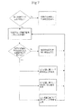
図7に示されるように、本発明によるシステムが注入液量を監視しているときは、システムは現在の注入流量を監視して、実際の流量と予め定めた流量とを比較する。注入流量が予め定めた流量より多いときは、システムは何の処置もしない。注入流量が予め定めた流量より少ないときは、超音波ハンドピースに送られる電力を変えて、外科医に対して変調音を発したり吸引圧力を変えたりするような、様々な処置をシステムが行うことができる。
【0041】
本発明によるシステムはまた、手術中の眼内圧(IOP)及び創傷の温度の少なくとも一方を制御するために使用できる。IOPを制御するために、使用者は所要のIOP値又はIOP値の範囲(IOPset)をCPU716に設定する。センサー722からの注入液ライン圧力情報(Pirr)はCPU716に与えられ、センサー727からの注入液供給源の圧力情報はCPU(Pbot)に与えられる。CPU716は、ハンドピース712からの流出量を次式を用いて特定する。
Flow=(Pbot−Pirr)/Rbot
ここでRbotは、センサー727とセンサー722との間の流体抵抗である。CPU716は、外科手術部位内の現在のIOP(IOPact)を次式を用いて算定する。
IOPact=Pirr−(Flow*Rirr)
ここでRirrは、センサー722と外科手術部位との間の流体抵抗である。CPUはIOPactとIOPsetとを比較し、IOPsetを維持するように与圧源729を調節する。CPU716の論理プロセスは、PIDアルゴリズム、ファジー論理アルゴリズム又は他の適当な全てのアルゴリズムのような様々な方法でプログラム可能である。選択的に、仮に与圧源530又は530’が使われるときは、ハンドピース712からの流出量は注入液供給源726の圧縮速度に比例するため、与圧源530又は530’はハンドピース712からの流出量を監視するために使用されることができ、センサー722は不要となる。
【0042】
本発明によるシステムはまた、創傷部位の温度制御に使用できる。創傷部位の温度を制御するために、使用者は創傷部位温度(Tempmax)及びCPU16、116、216、316又は416に要求される動作を選定する。選択的に、使用者は所要の温度範囲を選定してもよい。センサー22、122、222、322又は423からの注入液流量情報は、CPU16、116、216、316又は416にそれぞれ与えられ、またCPU16、116、216、316又は416は、注入液流量及び超音波パワーの現在及びそれ以前の値に基づいて、現在の創傷部位温度(Tempcur)を計算する。例えば、TempcurがTempmaxに達したときは、使用者は、超音波パワーを下げること、超音波パワーのデューティサイクル又は振幅を変えること、吸引圧力を変えるために注入圧力及び注入液流量の少なくとも一方を変えること又は可聴音を発することを要求できる。使用者は、Tempmaxとして選定した値又はTempcurがTempmaxに達したときの速度に対応して行われる、様々な動作をプログラムできる。CPU16、116、216、316又は416内の論理プロセスは、PIDアルゴリズム、ファジー論理アルゴリズム又は他の適当な全てのアルゴリズムのような様々な方法でプログラム可能である。
【0043】
本発明に関する記述は、図解及び説明のためになされたものである。関連した技術分野に熟練した者には、上述した本発明について、その特許請求の範囲や精神から逸脱することなく変化や修正が可能であることが明らかであろう。
【図面の簡単な説明】
【図1】
本発明に使用できる制御システムの第1の実施形態によるブロック線図である。
【図2】
本発明に使用できる制御システムの第2の実施形態によるブロック線図である。
【図3】
本発明に使用できる制御システムの第3の実施形態によるブロック線図であって、装置内の流量センサー及び注入液供給源の与圧注入制御を示した図である。
【図4】
本発明に使用できる制御システムの第4の実施形態によるブロック線図であって、ハンドピース内の流量センサー及び注入液供給源の与圧注入制御を示した図である。
【図5】
本発明に使用できる制御システムの第5の実施形態によるブロック線図であって、装置内の流量センサー及び注入液流量を計算するための与圧源の空気流量測定を示した図である。
【図6】
本発明に使用できる制御システムの第6の実施形態によるブロック線図であって、圧縮される柔軟性バッグとしての与圧源と、注入液供給源の圧縮速度から計算される注入液の流れとを示した図である。
【図7】
本発明に使用できる注入流量制御モードにおける操作を示したフローチャートである。
【図8】
従来技術である重力送液注入方法を示した図である。
【図9】
従来技術である与圧注入方法を示した図である。
【図10】
本発明による柔軟性容器の1つの実施形態を示したブロック線図であって、容器がローラー間で圧縮される状態を示した図である。
【図11】
本発明による柔軟性容器のもう1つの実施形態を示したブロック線図であって、容器が圧縮板によって圧縮される状態を示した図である。
【図12】
本発明に使用できる制御システムのもう1つの実施形態を示すブロック線図であって、洗浄ライン圧力センサー及び注入液供給源の与圧注入制御装置を有する制御を示す図である。[0001]
Background of the invention
The present invention relates generally to the field of cataract surgery, and more particularly to an injection control system for a phacoemulsification handpiece.
[0002]
Briefly, the human eye has the function of providing vision by transmitting light through a transparent outer portion called the cornea and focusing the image on the retina using the lens. The quality of the focused image depends on many factors, including the size and shape of the eye and the transparency of the cornea and lens.
[0003]
When the clarity of the lens is reduced due to aging or disease, the light transmitted to the retina is reduced, resulting in reduced vision. This defect in the lens of the eye is medically known as cataract. The accepted treatment for this condition is to surgically remove the lens and replace it with a lens that works with an artificial intraocular lens (IOL).
[0004]
In the United States, the majority of cataractous lenses are removed by a surgical technique called phacoemulsification. During this procedure, a thin cutting tip for phacoemulsification is inserted into the diseased lens and ultrasonically oscillated. The vibrating cutting tip fluidizes or emulsifies the lens to allow the lens to be aspirated out of the eye. After the diseased lens is removed, it is replaced with an artificial lens.
[0005]
A typical ultrasonic surgical device suitable for ophthalmic treatment has an ultrasonically vibrating handpiece, a cutting tip attached thereto, and a cleaning sleeve and an electronic controller. The handpiece assembly is attached to the controller by cables and flexible lines. The controller varies the level of power delivered by the handpiece to the attached cutting tip through a cable, and the flexible lines supply irrigation fluid to the eye and draw aspirate fluid from the eye through the handpiece assembly.
[0006]
The moving part of the handpiece is a centrally located, hollow, resonating bar or horn, which is attached directly to a set of piezoelectric crystals. The transducer provides the necessary ultrasonic vibration to actuate the horn and the cutting tip while the horn and the attached cutting tip are controlled by the controller and while performing phacoemulsification. The vibrator and horn assembly is supported by a free mount within the hollow body or body of the handpiece. The distal end of the handpiece body is a reduced diameter portion or a nose cone. The nose cone has an external thread for screwing the cleaning sleeve. Similarly, the hole in the horn has an internal thread at its end for threading with the external thread of the cutting tip. The cleaning sleeve also has a hole with an internal thread that threadably engages the external thread of the nose cone. The cutting tip is adjusted so that the tip projects a predetermined amount past the open end of the cleaning sleeve. Ultrasonic handpieces and cutting tips are disclosed in U.S. Pat. Nos. 3,589,363, 4,223,676, 4,246,902, 4,493,694, 4,515,583, 4,589, Nos. 415, 4,609,368, 4,869,715, 4,922,902, 4,989,583, 5,154,694 and 5,359,996. And their entire contents are cited as related art in the present application.
[0007]
In use, the cutting tip and the end of the irrigation sleeve are inserted into a small incision of a predetermined width in the cornea, sclera or elsewhere. The cutting tip is ultrasonically oscillated in the irrigation sleeve along the longitudinal axis of the tip by an ultrasonic horn driven by a transducer, thereby emulsifying the selected tissue in place. The hollow hole of the cutting tip communicates with the hole of the horn, which in turn communicates with the suction line from the handpiece to the controller. A reduced pressure or vacuum source in the controller pulls or aspirates the emulsified tissue out of the eye through the open end of the cutting tip, the holes in the cutting tip and horn, and the suction line and into the collection device. Aspiration of the emulsified tissue is assisted by a saline flushing or irrigation solution that is injected into the surgical site through a small annular gap between the inner surface of the irrigation sleeve and the cutting tip.
[0008]
It is a preferred surgical technique to make the incision in the anterior chamber as small as possible to reduce the risk of causing astigmatism. These small incisions result in a very tight wound that tightens the irrigation sleeve against the vibrating tip. The friction between the irrigation sleeve and the vibrating tip generates heat, but the cooling effect of the aspirate flowing inside the tip reduces the risk of overheating of the tip and burns of the tissue. When the tip is occluded by tissue, the flow of this aspirate may decrease or stop and the tip may overheat.
[0009]
Prior art devices use sensors to detect a large increase in vacuum during suction and to predict blockage due to the increase in vacuum. This sensed occlusion allows for a reduction in power applied to the handpiece and / or an increase in irrigation and aspiration flow. See U.S. Patent Nos. 5,591,127, 5,700,240 and 5,766,146 (Barwick, Jr., etc.), the entire contents of which are incorporated herein by reference. However, an increase in the degree of vacuum in the suction line does not necessarily indicate that the flow rate of the coolant around the chip is interrupted. Even with the tightest incisions, some irrigation fluid leaks between the wound and the outside of the irrigation sleeve. Since the leakage from the wound becomes a flow for further cooling the incision site, only measuring the increase in the degree of vacuum at the time of suction does not necessarily indicate the potential for causing a burn to the cornea. Therefore, the power applied to the handpiece will be prematurely interrupted.
[0010]
Prior art devices also use gravity fluid delivery methods or pressurized gas sources to control surgical infusion pressure and flow rates. The pressure and flow rate based on the height of the liquid column can be obtained by the gravity liquid injection method as shown in FIG. As the liquid column gets higher, the pressure and flow rate increase. As the liquid column goes down, the pressure and flow rate go down. The surgeon adjusts the height of the liquid column by raising and lowering the bottle containing the infusate. A pressurized gas supply, such as that shown in FIG. 9, regulates the infusion pressure by increasing or decreasing the pressure inside the infusion bottle. The bottle is suspended at a certain height and a gas pressure pump is connected to the bottle. See U.S. Patent Nos. 4,813,927, 4,900,301, 5,032,111 and 5,047,009 (Morris et al.), The entire contents of which are incorporated herein by reference. thing. The gravity feed injection method has a limited response speed of the pressure resulting from the need to raise and lower the injection bottle. Pressurized gas supplies have improved response speeds, but require cumbersome venting tubing that complicates surgical preparation. Both methods require the air or gas in the bottle to be filtered to prevent contamination, which adds cost and complexity.
[0011]
Therefore, an infusion source for a surgical device that utilizes a better method of handling infusion pressure and flow is desired.
[0012]
Summary of the present invention
The present invention improves upon the prior art by providing a surgical infusion system having various infusate pressure sensors. The system also uses a compressible infusion container. The information provided by the infusate pressure sensor allows the user to predict and control intraocular pressure during surgery and temperature at the wound site during surgery.
[0013]
Accordingly, one object of the present invention is to provide a surgical device control system.
[0014]
It is another object of the present invention to provide a method of operating a surgical device control system that can sense irrigation fluid pressure.
[0015]
It is another object of the present invention to provide a method of operating a surgical device control system that more accurately controls operating parameters of a handpiece.
[0016]
It is another object of the present invention to provide a method of operating a surgical device control system that more accurately controls injection operating parameters.
[0017]
It is another object of the present invention to provide a method of operating a surgical device control system that more accurately controls suction operating parameters.
[0018]
It is another object of the present invention to provide a method of operating a surgical device control system that more accurately controls intraocular pressure during surgery.
[0019]
It is another object of the present invention to provide a method of operating a surgical device control system that more accurately controls the temperature of a wound site during surgery.
[0020]
It is another object of the present invention to provide faster and more accurate control of injection pressure and flow.
[0021]
These and other advantages and objectives of the invention will be apparent from the following detailed description, and from the claims.
[0022]
Detailed description of the invention
As shown in FIG. 1, in a first embodiment of the present invention, a control system 10 used for operating a handpiece 12 has a control device 14. The controller 14 typically includes a control module or CPU 16, a suction pump 18, a handpiece power supply 20, a cleaning liquid flow sensor 22, and a valve 24. Controller 14 may be any commercially available surgical controller, such as the ACCURUS® or LEGACY®SERIES®TWENTY @ THOUSAND® surgical system available from Alcon Laboratories, Inc. of Fort Worth, Texas. CPU 16 may be any suitable microprocessor, microcontroller, computer or digital logic controller. Pump 18 can be any suitable pump, such as a peristaltic pump, scroll pump, diaphragm pump, or venturi pump. The power supply 20 can be any suitable ultrasonic exciter, such as that incorporated into an ACCURUS® or LEGACY®SERIES®TWENTY®THOUSAND® surgical system available from Alcon Laboratories, Inc. of Fort Worth, Texas. . The sensor 22 can be any commercially available flow sensor, such as model number T101D or T201D available from Transonic Systems, Inc. of Isaak, NY. Any suitable valve may be used for valve 24, such as a solenoid operated pinch valve. All commercially available cleaning solutions can be used for the infusate supply source 26.
[0023]
In use, the sensor 22 is connected to the handpiece 12 and the infusate supply 26 via wash lines 30, 32 and. The sensor 22 measures the flow rate of the cleaning liquid from the supply source 26 to the handpiece 12 and provides this information to the CPU 16 through the cable 36. The cleaning fluid flow data can be used by CPU 16 to control operating parameters of controller 14 using software instructions well known in the art. For example, the CPU 16 can open and close the valve 24 through the cable 38 to change the amount of the cleaning liquid from the supply source 26 to the handpiece 12. The CPU 16 can also change the output of the power supply 20 sent to the handpiece 12 through the power cable 42 through the cable 40. CPU 16 can also use the data provided by sensor 22 to alter the operation of pump 18. Pump 18 draws liquid from handpiece 12 through line 46 and sends the liquid to collection container 28 through line 48.
[0024]
As shown in FIG. 2, in a second embodiment of the present invention, a control system 110 for use in operating a handpiece 112 has a controller 114. The controller 114 typically includes a control module or CPU 116, a suction pump 118, a handpiece power supply 120 and a valve 124. The flow sensor 122 is housed inside the handpiece 112.
[0025]
In use, tip 150 is connected to infusion supply 126 via sensor 122 and wash lines 130, 132 and 134. The sensor 122 measures the flow rate of the cleaning liquid from the supply source 126 to the chip 150, and provides this information to the CPU 116 via the cable 136. The CPU 116 can change the amount of the cleaning liquid from the supply source 126 to the tip 150 by opening and closing the valve 124 through the cable 138. The CPU 116 can also change the output of the power supply 120 sent to the handpiece 112 through the power cable 142 through the cable 140. CPU 116 can also use the data provided by sensor 122 to alter the operation of pump 118. Pump 118 draws liquid from handpiece 112 through line 146 and sends the liquid to collection container 128 through line 148. CPU 116 can also use the data provided by sensor 122 and the output provided by power supply 120 to emit an audible sound to the user.
[0026]
As shown in FIG. 3, in a third embodiment of the present invention, a control system 210 used for operating the handpiece 212 has a control device 214. The controller 214 typically includes a control module or CPU 216, a suction pump 218, a handpiece power supply 220, a valve 224, a pressurized source 229, and a pressure sensor 227. The flow sensor 222 is connected to the handpiece 212 and the infusate supply 226 via cleaning lines 230, 232 and 234. A commercially available cleaning solution provided in a bottle can be used for the infusate supply source 226. Pressurizing source 229 pressurizes infusate supply 226 through line 252 and is controlled by CPU 216 through cable 250. The pressurized source 229 can be any commercially available pressure controller, such as that incorporated in the ACCURUS® surgical system available from Alcon Laboratories, Inc. of Fort Worth, Texas. Pressure sensor 227 measures the pressure of infusate supply 226 via line 254 and is monitored by CPU 216 via cable 256. The pressure sensor 227 may be any suitable commercially available pressure sensor, such as model MPX5100 available from Motorola of Phoenix, Arizona.
[0027]
In use, the sensor 222 measures the flow rate of the cleaning liquid sent from the supply 226 to the handpiece 212 and provides that information to the CPU 216 via the cable 236. The cleaning fluid flow data can be used by CPU 216 to control operating parameters of controller 214 using software instructions well known in the art. For example, while reading the data of the pressure sensor 227 through the cable 256, the CPU 216 can control the pressurizing source 229 through the cable 250 to change the amount of the cleaning liquid from the supply source 226 to the handpiece 212. CPU 216 can also alter the output of power supply 220 sent to handpiece 212 through power cable 242 through cable 240. CPU 216 can also use the data provided by sensor 222 to alter the operation of pump 218 via line 244. Pump 218 draws liquid from handpiece 212 through line 246 and sends the liquid to collection container 228 through line 248. CPU 216 can also use the data provided by sensor 222 and the output provided by power supply 220 to emit an audible sound to the user.
[0028]
As shown in FIG. 4, in a fourth embodiment of the present invention, a control system 310 used for operating the handpiece 312 has a control device 314. The controller 314 typically includes a control module or CPU 316, a suction pump 318, a handpiece power supply 320, a valve 324, a pressurized source 329, and a pressure sensor 327. The flow sensor 322 is housed inside the handpiece 312. A commercially available cleaning solution provided in a bottle can be used for the infusion liquid supply source 326. All commercially available pressure controllers can be used for the pressurizing source 329. The pressure sensor 227 may be any suitable commercially available pressure sensor.
[0029]
During use, the sensor 322 measures the flow rate of the cleaning liquid sent from the source 326 to the handpiece 312 and provides that information to the CPU 316 via the cable 336. The cleaning fluid flow data can be used by CPU 316 to control operating parameters of controller 314 using software instructions well known in the art. For example, while reading the data of the pressure sensor 327 through the cable 356, the CPU 316 can control the pressurizing source 329 through the cable 350 to change the amount of the cleaning liquid from the supply source 326 to the handpiece 312. CPU 316 can also alter the output of power supply 320 sent to handpiece 312 through power cable 342 through cable 340. CPU 316 can also use the data provided by sensor 322 to alter the operation of pump 318 through cable 344. Pump 318 draws liquid from handpiece 312 through line 346 and sends the liquid to collection container 328 through line 348. CPU 316 can also use the data provided by sensor 322 and the output provided by power supply 320 to emit an audible sound to the user.
[0030]
As shown in FIG. 5, in a fifth embodiment of the present invention, a control system 410 used to operate the handpiece 412 has a control device 414. The controller 414 typically includes a control module or CPU 416, a suction pump 418, a handpiece power supply 420, a valve 424, a pressurized source 429, and a pressure sensor 527. Air flow sensor 423 is connected to pressurized source 429 and infusate supply 426 via lines 432 and 452. The sensor 423 can be any commercially available flow sensor, such as model AWM3100V available from Honeywell, Freeport, Illinois. A commercially available cleaning solution provided in a bottle can be used for the infusate supply source 426.
[0031]
In use, sensor 423 measures the amount of air flowing into supply 426 and provides that information to CPU 416 via cable 436. The air flow data is used by CPU 416 with information from pressure sensor 427 to calculate the infusate flow sent to the handpiece via line 434. This calculated infusion volume can be used to control operating parameters of the controller 414 using software instructions well known in the art. For example, while reading the data of the pressure sensor 427 through the cable 456, the CPU 416 can control the pressurizing source 429 through the cable 450 to change the amount of the cleaning liquid from the supply source 426 to the handpiece 412. The CPU 416 can also change the output of the power supply 420 sent to the handpiece 412 through the power cable 442 through the cable 440. CPU 416 can also use the calculated infusate flow rate to alter the operation of pump 418 through cable 444. Pump 418 draws liquid from handpiece 412 via power cable 442. CPU 416 can also use the calculated infusate volume to modify the operation of pump 418 through cable 444. Pump 418 draws liquid from handpiece 412 through line 446 and sends the liquid to collection container 428 through line 448. The CPU 416 can also use the calculated infusate flow rate and the output provided by the power supply 420 to generate an audible tone to the user.
[0032]
As shown in FIG. 6, in a sixth embodiment of the present invention, a control system 510 used to operate the handpiece 512 has a control device 514. The controller 514 typically includes a control module or CPU 516, a suction pump 518, a handpiece power supply 520, a valve 524, a pressurized source 530, and a pressure sensor 527. The infusion source 525 can be any commercially available cleaning solution provided in a bag or conventional flexible container. Pressurizing source 530 is a compression device that compresses infusate supply 525 through mechanism 553 to pressurize the liquid. The compression ratio of the infusate supply is controlled by CPU 516 through cable 550.
[0033]
In use, the CPU 516 calculates the flow rate of infusate sent to the handpiece through the line 534 based on the compression ratio of the pressurized source 530 and the pressure data from the pressure sensor 527. The pressure sensor 527 can be in communication with the infusate supply 525 either directly or through a cleaning line 533 or 534. This calculated infusion volume can be used to control operating parameters of controller 514 using software instructions well known in the art. For example, while reading the data of the pressure sensor 527 through the cable 556, the CPU 516 can control the pressurizing source 530 through the cable 550 to change the amount of the cleaning liquid from the supply source 525 to the handpiece 512. The CPU 516 can also change the output of the power supply 520 sent to the handpiece 512 through the power cable 542 through the cable 540. CPU 516 can also use the calculated infusate flow rate to alter the operation of pump 518 through cable 544. Pump 518 draws liquid from handpiece 512 through line 546 and sends the liquid to collection container 528 through line 548. The CPU 516 can also use the calculated infusate flow rate and the output provided by the power supply 520 to emit an audible tone to the user.
[0034]
As shown in FIG. 10, the pressurizing source 530 includes a roller mechanism 553, an infusion liquid container 525, a pressure sensor 527, and an injection or cleaning valve 524. The roller mechanism 553 has a compression roller 554 and a roller drive motor 555. The infusion container 525 may be a flexible bag for surgical infusion into a site or a customary container having a special construction for this application, such as those commonly available from Charter Medical, Inc. of Lakewood, NJ. Can be used. The infusate container 525 can be made from any suitable material that results in a container that can be compressed without excessive stretching. The infusate container 525 may be a thin walled bottle and may or may not have a wavy side (not shown). The pressure sensor 527 can be any commercially available disposable pressure sensor, such as Hewlett-Packard Model 1290C, or a custom-made sensor specifically made for this application. The injection valve 524 may be any commercially available pinch-type valve commonly used in surgical devices. The compression roller mechanism 553 has a two-way mechanical roller 554 and a suitable structure that compresses the flexible container 525 in a controlled and uniform manner, such that the compression rate is proportional to the liquid discharge rate. Jig.
[0035]
In use, the flexible container 525 is disposed within the roller mechanism 553 and is connected to the cleaning line 533. The injection valve 524 is open and the roller mechanism 553 moves to compress the container 525. Movement of the roller mechanism 554 reduces the effective volume in the container 525, thereby forcing the infusate into the wash line 533. The information from the pressure sensor 527 indicates that the injection pressure and the roller mechanism 553 are controlled to maintain a predetermined injection pressure read value. The speed of movement of the drive motor 555 is proportional to the liquid discharge speed, and that information is used by the control system 510 for further systematic control.
[0036]
As shown in FIG. 11, the pressurized source 530 'has an infusate container 525', a mechanism 553 ', a pressure sensor 527', and a valve 524 '. The mechanism 553 'includes a compression actuator 103, an upper plate 105, a lower plate 107, and a plate return spring 106. The compression actuator 103 includes a worm gear and a hydraulically driven actuator having a structure that presses the plate 105 in a controlled and uniform manner, and the pressing speed is proportional to the liquid discharge speed from the container 525 ′. Any of them may be used. The return spring 106 can be any commercially available spring that can be used to return the plate to its original position.
[0037]
In use, the flexible container 525 ′ is arranged to receive pressure from the upper plate 105 and the lower plate 107 and is connected to the cleaning line 533. Injection valve 524 'is open and actuator 103 exerts downward pressure on plate 105 against spring 106. The downward pressure applied to the plate 105 compresses the container 525 'between the upper plate 105 and the lower plate 107, thereby reducing the effective volume in the container 525' and causing the infusate to flow into the wash line 533 '. It is forcibly moved inside. The information from the pressure sensor 527 'indicates that the injection pressure and actuator 103 have been controlled to maintain a predetermined injection pressure reading. The movement speed of the actuator 103 is proportional to the liquid discharge speed, and that information is used by the control system 510 for further systematic control.
[0038]
As shown in FIG. 12, in another embodiment of the present invention, the control system 710 used to operate the handpiece 712 has a controller 714. The controller 714 typically includes a control module or CPU 716, a suction pump 718, a handpiece power supply 720, a valve 724, a pressurized source 729, and an infusate source pressure sensor 727. Irrigation line pressure sensor 722 is connected to handpiece 712 and infusion supply 726 through irrigation lines 730, 732 and 734. The infusion supply 726 can be any commercially available cleaning solution provided in a bottle. Pressurizing source 729 pressurizes infusate supply 726 through line 752 and is controlled by CPU 716 through cable 750. The pressurized source 729 can be any commercially available pressure controller, such as that incorporated into the ACCURUS® surgical system available from Alcon Laboratories, Inc. of Fort Worth, Texas. Pressurized source 729 may also be similar to pressurized source 530 or 530 'shown in FIGS. Pressure sensor 727 measures the pressure of infusate supply 726 via line 754 and is monitored by CPU 716 via cable 756. Pressure sensors 722 and 727 can be any suitable commercially available flow sensor, such as model MPX5100, available from Motorola of Phoenix, Arizona. For those skilled in the art, an air flow sensor 423 may be used in addition to or instead of the sensor 727 so that the pressure within the infusate supply 726 may be reduced from the operation of the pressurized source 530 or 530 '. It will be appreciated that it can be given.
[0039]
In use, the sensor 722 measures the pressure of the cleaning liquid in the cleaning line 734 at (ie, within) the handpiece 712 and provides that information to the CPU 716 through the cable 736. The wash line pressure data can be used by CPU 716 to control operating parameters of controller 714, as described below, using software instructions well known in the art. For example, while reading the data of the pressure sensor 727 through the cable 756, the CPU 716 can control the pressurizing source 729 through the cable 750 to change the amount of the cleaning liquid from the supply source 726 to the handpiece 712. CPU 716 can also alter the output of power supply 720 sent to handpiece 712 through power cable 742 through cable 740. CPU 716 can also use the data provided by sensor 722 to alter the operation of pump 718 over line 744. Pump 718 draws liquid from handpiece 712 through line 746 and sends the liquid to collection container 728 through line 748. CPU 716 can also use the data provided by sensor 722 and the output provided by power supply 720 to emit an audible sound to the user.
[0040]
As shown in FIG. 7, when the system according to the present invention is monitoring the infusate volume, the system monitors the current infusion flow rate and compares the actual flow rate with a predetermined flow rate. If the infusion flow is higher than the predetermined flow, the system takes no action. When the infusion flow rate is less than the predetermined flow rate, the system can perform various procedures, such as changing the power delivered to the ultrasound handpiece, producing a modulating sound for the surgeon, or changing the suction pressure. Can be.
[0041]
The system according to the invention can also be used to control intra-operative intraocular pressure (IOP) and / or wound temperature. In order to control the IOP, the user must enter the required IOP value or range of IOP values (IOPset) Is set in the CPU 716. Injection line pressure information from sensor 722 (Pirr) Is supplied to the CPU 716, and pressure information of the infusion liquid supply source from the sensor 727 is supplied to the CPU (Pbot). The CPU 716 specifies the outflow amount from the handpiece 712 using the following equation.
Flow = (Pbot-Pirr) / Rbot
Where RbotIs the fluid resistance between sensor 727 and sensor 722. The CPU 716 determines the current IOP (IOP) within the surgical site.act) Is calculated using the following equation.
IOPact= Pirr-(Flow * Rirr)
Where RirrIs the fluid resistance between the sensor 722 and the surgical site. CPU is IOPactAnd IOPsetAnd IOPsetIs adjusted to maintain the pressure. The logic processes of CPU 716 can be programmed in various ways, such as a PID algorithm, a fuzzy logic algorithm, or any other suitable algorithm. Optionally, if pressurized source 530 or 530 'is used, pressurized source 530 or 530' may be connected to handpiece 712 because the amount of flow out of handpiece 712 is proportional to the compression rate of infusate supply 726. Can be used to monitor the amount of effluent from the system, eliminating the need for a sensor 722.
[0042]
The system according to the invention can also be used for controlling the temperature of a wound site. In order to control the temperature of the wound site, the user selects the wound site temperature (Tempmax) And the operations required by the CPU 16, 116, 216, 316 or 416 are selected. Optionally, the user may select the required temperature range. Infusion fluid flow information from sensors 22, 122, 222, 322 or 423 is provided to CPUs 16, 116, 216, 316 or 416, respectively, and CPUs 16, 116, 216, 316 or 416 provide infusion fluid flow and ultrasound Based on the current and previous values of power, the current wound site temperature (Tempcur) Is calculated. For example, TempcurIs TempmaxWhen the user has reached the point, the user can reduce the ultrasonic power, change the duty cycle or amplitude of the ultrasonic power, change the infusion pressure and / or the infusate flow to change the suction pressure, or change the audible sound. Can be requested. The user is TempmaxValue or Temp selected ascurIs TempmaxVarious actions can be programmed to be performed in response to the speed when the speed is reached. The logic processes within the CPU 16, 116, 216, 316 or 416 can be programmed in various ways, such as a PID algorithm, a fuzzy logic algorithm or any other suitable algorithm.
[0043]
The description of the present invention has been presented for purposes of illustration and description. It will be apparent to those skilled in the relevant art that changes and modifications may be made to the invention described above without departing from the scope and spirit of the invention.
[Brief description of the drawings]
FIG.
1 is a block diagram according to a first embodiment of a control system that can be used in the present invention.
FIG. 2
FIG. 4 is a block diagram according to a second embodiment of a control system that can be used in the present invention.
FIG. 3
FIG. 10 is a block diagram of a control system according to a third embodiment that can be used in the present invention, illustrating a pressurized injection control of a flow sensor and an infusate supply source in the apparatus.
FIG. 4
FIG. 11 is a block diagram of a control system according to a fourth embodiment that can be used in the present invention, illustrating pressurized injection control of a flow sensor and an infusate supply source in a handpiece.
FIG. 5
FIG. 9 is a block diagram of a control system according to a fifth embodiment that can be used in the present invention, illustrating a flow sensor in the apparatus and air flow measurement of a pressurized source for calculating an infusate flow rate.
FIG. 6
FIG. 13 is a block diagram according to a sixth embodiment of a control system that can be used in the present invention, comprising a pressurized source as a flexible bag to be compressed, and an infusate flow calculated from the compression rate of the infusate supply. FIG.
FIG. 7
5 is a flowchart showing an operation in an injection flow control mode that can be used in the present invention.
FIG. 8
It is the figure which showed the gravity liquid feeding injection method which is a prior art.
FIG. 9
It is the figure which showed the pressurization injection method which is a prior art.
FIG. 10
FIG. 3 is a block diagram illustrating one embodiment of a flexible container according to the present invention, showing the container being compressed between rollers.
FIG. 11
FIG. 4 is a block diagram showing another embodiment of the flexible container according to the present invention, showing a state where the container is compressed by a compression plate.
FIG.
FIG. 4 is a block diagram illustrating another embodiment of a control system that can be used with the present invention, illustrating control having a flush line pressure sensor and a pressurized injection control of an infusate supply.
Claims (28)
a.i)制御モジュール、
ii)注入液供給源に与圧するための与圧源、
iii)注入液供給源圧力センサー及び
iv)洗浄ライン圧力センサー
を有する制御装置を用意するステップと、
b.手術中の所要の眼内圧を選定するステップと、
c.前記洗浄ライン圧力センサーから洗浄ライン圧力情報を前記制御モジュールに与えるステップと、
d.前記注入液供給源圧力センサーから注入液供給源圧力情報を前記制御モジュールに与えるステップと、
e.前記制御モジュールに与えられる前記洗浄ライン圧力情報及び前記注入液供給源圧力情報を用いて手術中の眼内圧を計算するステップと、
f.前記計算された手術中の眼内圧を前記選定された手術中の所要の眼内圧と比較するステップと、
g.前記計算された手術中の眼内圧と前記選定された手術中の所要の眼内圧との間の前記比較に基づいて前記与圧源の動作を調節するステップと、
を有する方法。A method of controlling intraocular pressure during surgery,
a. i) a control module,
ii) a pressurized source for pressurizing the infusate supply;
iii) providing a controller having an infusate source pressure sensor and iv) a flush line pressure sensor;
b. Selecting the required intraocular pressure during the operation;
c. Providing cleaning line pressure information to the control module from the cleaning line pressure sensor;
d. Providing infusate supply pressure information to the control module from the infusate supply pressure sensor;
e. Calculating intra-operative intraocular pressure using the irrigation line pressure information and the infusate source pressure information provided to the control module;
f. Comparing the calculated intraoperative intraocular pressure with the selected intraoperative required intraocular pressure;
g. Adjusting the operation of the pressurized source based on the comparison between the calculated intraoperative intraocular pressure and the selected intraoperative required intraocular pressure;
Having a method.
a.i)制御モジュール、
ii)ハンドピース電源及び
iii)注入液流れを測定する手段
を有する制御装置を用意するステップと、
b.手術中の所要の創傷部位温度を選定するステップと、
c.注入液流れ情報を前記制御モジュールに与えるステップと、
d.前記ハンドピース電源からハンドピース電力情報を前記制御モジュールに与えるステップと、
e.現在及びそれ以前の注入液流量及びハンドピース電力の値に基づいて、前記創傷部位における現在温度を計算するステップと、
f.前記創傷部位の前記計算された現在温度と前記選定された手術中の所要の創傷部位温度とを比較するステップと、
g.前記創傷部位の前記計算された現在温度と前記選定された手術中の所要の創傷部位温度との間の前記比較に基づいて、前記ハンドピース電源の動作を調節するステップと、
を有する方法。A method of controlling the temperature of a wound site during surgery,
a. i) a control module,
ii) providing a controller having a handpiece power supply and iii) means for measuring the infusate flow;
b. Selecting the required wound site temperature during the operation;
c. Providing infusate flow information to the control module;
d. Providing handpiece power information from the handpiece power supply to the control module;
e. Calculating a current temperature at the wound site based on current and previous infusate flow and handpiece power values;
f. Comparing the calculated current temperature of the wound site with the required wound site temperature during the selected operation;
g. Adjusting the operation of the handpiece power supply based on the comparison between the calculated current temperature of the wound site and the required wound site temperature during the selected operation.
Having a method.
a.i)制御モジュール、
ii)注入液供給源に与圧するための与圧源及び
iii)注入液供給源圧力センサー
を有する制御装置を用意するステップと、
b.手術中の所要の眼内圧を選定するステップと、
c.洗浄ライン液体流れ及び注入液供給源圧力情報を前記制御モジュールに与えるステップと、
d.前記制御モジュールに与えられる前記洗浄ライン液体流れ情報及び前記注入液供給源圧力情報を用いて手術中の眼内圧を計算するステップと、
e.前記計算された手術中の眼内圧を前記選定された手術中の所要の眼内圧と比較するステップと、
f.前記計算された手術中の眼内圧と前記選定された手術中の所要の眼内圧との間の前記比較に基づいて前記与圧源の動作を調節するステップと、
を有する方法。A method of controlling intraocular pressure during surgery,
a. i) a control module,
ii) providing a control device having a pressurized source for pressurizing the infusate supply source and iii) an infusate source pressure sensor;
b. Selecting the required intraocular pressure during the operation;
c. Providing wash line liquid flow and infusate source pressure information to the control module;
d. Calculating intra-operative intraocular pressure using the irrigation line liquid flow information and the infusate source pressure information provided to the control module;
e. Comparing the calculated intraoperative intraocular pressure with the selected intraoperative required intraocular pressure;
f. Adjusting the operation of the pressurized source based on the comparison between the calculated intraoperative intraocular pressure and the selected intraoperative required intraocular pressure;
Having a method.
Applications Claiming Priority (2)
| Application Number | Priority Date | Filing Date | Title |
|---|---|---|---|
| US65154100A | 2000-08-29 | 2000-08-29 | |
| PCT/US2001/024702 WO2002017833A1 (en) | 2000-08-29 | 2001-08-07 | Method of controlling intraocular pressure and temperature |
Publications (2)
| Publication Number | Publication Date |
|---|---|
| JP2004507321A true JP2004507321A (en) | 2004-03-11 |
| JP2004507321A5 JP2004507321A5 (en) | 2005-06-23 |
Family
ID=24613239
Family Applications (1)
| Application Number | Title | Priority Date | Filing Date |
|---|---|---|---|
| JP2002522809A Pending JP2004507321A (en) | 2000-08-29 | 2001-08-07 | Injection control system |
Country Status (7)
| Country | Link |
|---|---|
| EP (2) | EP1225854A1 (en) |
| JP (1) | JP2004507321A (en) |
| AU (1) | AU766716B2 (en) |
| BR (1) | BR0107148A (en) |
| CA (1) | CA2385779A1 (en) |
| IL (1) | IL149190A0 (en) |
| WO (1) | WO2002017833A1 (en) |
Cited By (9)
| Publication number | Priority date | Publication date | Assignee | Title |
|---|---|---|---|---|
| JP2007530146A (en) * | 2004-03-22 | 2007-11-01 | アルコン,インコーポレイティド | Surgical system control method based on handpiece cutting tip load |
| JP2007530145A (en) * | 2004-03-22 | 2007-11-01 | アルコン,インコーポレイティド | Surgical system control method based on irrigation flow rate |
| JP2013513427A (en) * | 2009-12-09 | 2013-04-22 | アルコン リサーチ, リミテッド | Temperature management algorithm for phacoemulsification system |
| JP2013520276A (en) * | 2010-02-26 | 2013-06-06 | デー.オー.エル.セー.ダッチ、オフサルミック、リサーチ、センター、(インターナショナル)、ベスローテン、フェンノートシャップ | Ophthalmic system and computer program product |
| CN104080395A (en) * | 2011-12-02 | 2014-10-01 | Ljt工程有限公司 | Tear duct resistance measuring system |
| JP2015504349A (en) * | 2011-11-30 | 2015-02-12 | アルコン リサーチ, リミテッド | Retinal surgery |
| JP2015532171A (en) * | 2012-10-22 | 2015-11-09 | アルコン リサーチ, リミテッド | Pressure control in phacoemulsification system |
| JP2015536168A (en) * | 2012-10-22 | 2015-12-21 | アルコン リサーチ, リミテッド | Pressure control in phacoemulsification system |
| US11311661B2 (en) | 2018-03-09 | 2022-04-26 | D.O.R.C. Dutch Ophthalmic Research Center (International) B.V. | Ophthalmic pressure control system, a kit of parts and a method |
Families Citing this family (22)
| Publication number | Priority date | Publication date | Assignee | Title |
|---|---|---|---|---|
| WO2007008437A1 (en) * | 2005-07-07 | 2007-01-18 | Alcon, Inc. | Surgical system |
| CA2690197C (en) * | 2007-06-19 | 2015-12-01 | Alcon Research Ltd. | Post-occlusion chamber collapse canceling system for a surgical apparatus and method of use |
| US8623040B2 (en) | 2009-07-01 | 2014-01-07 | Alcon Research, Ltd. | Phacoemulsification hook tip |
| US20110118728A1 (en) * | 2009-11-13 | 2011-05-19 | Alcon Research, Ltd. | Control of high-intensity pulsed electrical fields in surgical applications |
| US8689439B2 (en) | 2010-08-06 | 2014-04-08 | Abbott Laboratories | Method for forming a tube for use with a pump delivery system |
| US10258505B2 (en) | 2010-09-17 | 2019-04-16 | Alcon Research, Ltd. | Balanced phacoemulsification tip |
| US8377000B2 (en) | 2010-10-01 | 2013-02-19 | Abbott Laboratories | Enteral feeding apparatus having a feeding set |
| US8377001B2 (en) | 2010-10-01 | 2013-02-19 | Abbott Laboratories | Feeding set for a peristaltic pump system |
| DK2766064T3 (en) | 2011-12-08 | 2016-11-07 | Alcon Res Ltd | SELECTIVE MOVING VALVE ELEMENTS for extraction and OVERRISLINGSKREDSLØB |
| NL2009424C2 (en) | 2012-09-06 | 2014-03-10 | D O R C Dutch Ophthalmic Res Ct International B V | Irrigation/aspiration system, cartridge, pump unit, surgical machine, method for controlling. |
| US20180318131A1 (en) * | 2012-10-22 | 2018-11-08 | Alcon Research, Ltd. | Pressure control in phacoemulsification system |
| US9433723B2 (en) * | 2013-03-14 | 2016-09-06 | Abbott Medical Optics Inc. | System and method for providing pressurized infusion |
| US9205186B2 (en) | 2013-03-14 | 2015-12-08 | Abbott Medical Optics Inc. | System and method for providing pressurized infusion |
| US9597229B2 (en) * | 2013-03-15 | 2017-03-21 | Abbott Medical Optics Inc. | Phacoemulsification flow rate detection system and method |
| US9549850B2 (en) | 2013-04-26 | 2017-01-24 | Novartis Ag | Partial venting system for occlusion surge mitigation |
| US10137034B2 (en) | 2013-11-26 | 2018-11-27 | Novartis Ag | Pressure-sensing vitrectomy surgical systems and methods |
| AU2015259400B2 (en) | 2014-05-12 | 2019-12-19 | Smith & Nephew, Inc. | Closed loop surgical system |
| CA2948827A1 (en) * | 2014-05-13 | 2015-11-19 | Abbott Medical Optics Inc. | System and method for providing pressurized infusion |
| EP3458002A1 (en) | 2016-05-17 | 2019-03-27 | Novartis AG | Automated viscous fluid control in vitreoretinal surgery |
| US20180028359A1 (en) * | 2016-07-28 | 2018-02-01 | Novartis Ag | Pressure control in phacoemulsification system |
| US11357907B2 (en) | 2017-02-10 | 2022-06-14 | Johnson & Johnson Surgical Vision, Inc. | Apparatus, system, and method of gas infusion to allow for pressure control of irrigation in a surgical system |
| US11154421B2 (en) | 2018-04-20 | 2021-10-26 | Johnson & Johnson Surgical Vision, Inc. | System and method for providing pressurized infusion transfer reservoirs |
Family Cites Families (15)
| Publication number | Priority date | Publication date | Assignee | Title |
|---|---|---|---|---|
| NL145136C (en) | 1967-07-25 | 1900-01-01 | ||
| US4223676A (en) | 1977-12-19 | 1980-09-23 | Cavitron Corporation | Ultrasonic aspirator |
| US4246902A (en) | 1978-03-10 | 1981-01-27 | Miguel Martinez | Surgical cutting instrument |
| US4493694A (en) | 1980-10-17 | 1985-01-15 | Cooper Lasersonics, Inc. | Surgical pre-aspirator |
| US4515583A (en) | 1983-10-17 | 1985-05-07 | Coopervision, Inc. | Operative elliptical probe for ultrasonic surgical instrument and method of its use |
| US4609368A (en) | 1984-08-22 | 1986-09-02 | Dotson Robert S Jun | Pneumatic ultrasonic surgical handpiece |
| US4589415A (en) | 1984-08-31 | 1986-05-20 | Haaga John R | Method and system for fragmenting kidney stones |
| US4869715A (en) | 1988-04-21 | 1989-09-26 | Sherburne Fred S | Ultrasonic cone and method of construction |
| FR2642297A1 (en) * | 1989-02-02 | 1990-08-03 | Sinergy Sa | APPARATUS FOR IRRIGATION AND SUCTION FOR USE IN ENDOSCOPIC SURGERY |
| US5342313A (en) * | 1992-11-02 | 1994-08-30 | Infusion Technologies Corporation | Fluid pump for a flexible, variable geometry reservoir |
| US5403276A (en) * | 1993-02-16 | 1995-04-04 | Danek Medical, Inc. | Apparatus for minimally invasive tissue removal |
| US6083193A (en) * | 1998-03-10 | 2000-07-04 | Allergan Sales, Inc. | Thermal mode phaco apparatus and method |
| US6155975A (en) * | 1998-11-06 | 2000-12-05 | Urich; Alex | Phacoemulsification apparatus with personal computer |
| BR0011764A (en) * | 1999-06-18 | 2003-07-08 | Alcon Mfg Ltd | Infusion Control System |
| US6179808B1 (en) * | 1999-06-18 | 2001-01-30 | Alcon Laboratories, Inc. | Method of controlling the operating parameters of a surgical system |
-
2001
- 2001-08-07 AU AU81131/01A patent/AU766716B2/en not_active Ceased
- 2001-08-07 CA CA002385779A patent/CA2385779A1/en not_active Abandoned
- 2001-08-07 BR BR0107148-3A patent/BR0107148A/en not_active Application Discontinuation
- 2001-08-07 EP EP01959592A patent/EP1225854A1/en not_active Withdrawn
- 2001-08-07 IL IL14919001A patent/IL149190A0/en unknown
- 2001-08-07 JP JP2002522809A patent/JP2004507321A/en active Pending
- 2001-08-07 EP EP02025743A patent/EP1285642A1/en not_active Withdrawn
- 2001-08-07 WO PCT/US2001/024702 patent/WO2002017833A1/en active IP Right Grant
Cited By (13)
| Publication number | Priority date | Publication date | Assignee | Title |
|---|---|---|---|---|
| JP2007530146A (en) * | 2004-03-22 | 2007-11-01 | アルコン,インコーポレイティド | Surgical system control method based on handpiece cutting tip load |
| JP2007530145A (en) * | 2004-03-22 | 2007-11-01 | アルコン,インコーポレイティド | Surgical system control method based on irrigation flow rate |
| JP2013513427A (en) * | 2009-12-09 | 2013-04-22 | アルコン リサーチ, リミテッド | Temperature management algorithm for phacoemulsification system |
| JP2013520276A (en) * | 2010-02-26 | 2013-06-06 | デー.オー.エル.セー.ダッチ、オフサルミック、リサーチ、センター、(インターナショナル)、ベスローテン、フェンノートシャップ | Ophthalmic system and computer program product |
| US9517162B2 (en) | 2011-11-30 | 2016-12-13 | Alcon Research, Ltd. | Retinal surgery |
| JP2015504349A (en) * | 2011-11-30 | 2015-02-12 | アルコン リサーチ, リミテッド | Retinal surgery |
| JP2015505685A (en) * | 2011-12-02 | 2015-02-26 | エルジェーティー プロジェクツ リミテッド | Lacrimal flow resistance measurement system |
| CN104080395A (en) * | 2011-12-02 | 2014-10-01 | Ljt工程有限公司 | Tear duct resistance measuring system |
| JP2015532171A (en) * | 2012-10-22 | 2015-11-09 | アルコン リサーチ, リミテッド | Pressure control in phacoemulsification system |
| JP2015536168A (en) * | 2012-10-22 | 2015-12-21 | アルコン リサーチ, リミテッド | Pressure control in phacoemulsification system |
| US10052228B2 (en) | 2012-10-22 | 2018-08-21 | Alcon Research, Ltd. | Pressure control in phacoemulsification system |
| US11510811B2 (en) | 2012-10-22 | 2022-11-29 | Alcon Inc. | Pressure control in phacoemulsification system |
| US11311661B2 (en) | 2018-03-09 | 2022-04-26 | D.O.R.C. Dutch Ophthalmic Research Center (International) B.V. | Ophthalmic pressure control system, a kit of parts and a method |
Also Published As
| Publication number | Publication date |
|---|---|
| AU8113101A (en) | 2002-03-13 |
| CA2385779A1 (en) | 2002-03-07 |
| EP1225854A1 (en) | 2002-07-31 |
| WO2002017833A1 (en) | 2002-03-07 |
| BR0107148A (en) | 2002-07-02 |
| IL149190A0 (en) | 2002-11-10 |
| EP1285642A1 (en) | 2003-02-26 |
| AU766716B2 (en) | 2003-10-23 |
Similar Documents
| Publication | Publication Date | Title |
|---|---|---|
| EP1187643B1 (en) | Irrigation control system | |
| US6491661B1 (en) | Infusion control system | |
| AU766716B2 (en) | Method of controlling intraocular pressure and temperature | |
| AU2013257535B2 (en) | Phacoemulsification hand piece with integrated aspiration pump | |
| US9282989B2 (en) | Method of controlling a surgical system based on a load on the cutting tip of a handpiece | |
| CA2559499C (en) | Method of controlling a surgical system based on irrigation flow | |
| US7727193B2 (en) | Method of controlling a surgical system based on a rate of change of an operating parameter | |
| US8579929B2 (en) | Torsional ultrasound hand piece that eliminates chatter | |
| AU2009204162B2 (en) | Suction control for phacoemulsification aspiration system | |
| MXPA02003105A (en) | Method of controlling intraocular pressure and temperature. | |
| WO2002026016A2 (en) | Method of operating an infusion control system |
Legal Events
| Date | Code | Title | Description |
|---|---|---|---|
| A131 | Notification of reasons for refusal |
Free format text: JAPANESE INTERMEDIATE CODE: A131 Effective date: 20060221 |
|
| A02 | Decision of refusal |
Free format text: JAPANESE INTERMEDIATE CODE: A02 Effective date: 20060711 |