JP2016152178A - Lamination device - Google Patents
Lamination device Download PDFInfo
- Publication number
- JP2016152178A JP2016152178A JP2015030127A JP2015030127A JP2016152178A JP 2016152178 A JP2016152178 A JP 2016152178A JP 2015030127 A JP2015030127 A JP 2015030127A JP 2015030127 A JP2015030127 A JP 2015030127A JP 2016152178 A JP2016152178 A JP 2016152178A
- Authority
- JP
- Japan
- Prior art keywords
- separator
- electrode plate
- holding
- suction
- section
- Prior art date
- Legal status (The legal status is an assumption and is not a legal conclusion. Google has not performed a legal analysis and makes no representation as to the accuracy of the status listed.)
- Pending
Links
Images


Classifications
-
- Y—GENERAL TAGGING OF NEW TECHNOLOGICAL DEVELOPMENTS; GENERAL TAGGING OF CROSS-SECTIONAL TECHNOLOGIES SPANNING OVER SEVERAL SECTIONS OF THE IPC; TECHNICAL SUBJECTS COVERED BY FORMER USPC CROSS-REFERENCE ART COLLECTIONS [XRACs] AND DIGESTS
- Y02—TECHNOLOGIES OR APPLICATIONS FOR MITIGATION OR ADAPTATION AGAINST CLIMATE CHANGE
- Y02E—REDUCTION OF GREENHOUSE GAS [GHG] EMISSIONS, RELATED TO ENERGY GENERATION, TRANSMISSION OR DISTRIBUTION
- Y02E60/00—Enabling technologies; Technologies with a potential or indirect contribution to GHG emissions mitigation
- Y02E60/10—Energy storage using batteries
-
- Y—GENERAL TAGGING OF NEW TECHNOLOGICAL DEVELOPMENTS; GENERAL TAGGING OF CROSS-SECTIONAL TECHNOLOGIES SPANNING OVER SEVERAL SECTIONS OF THE IPC; TECHNICAL SUBJECTS COVERED BY FORMER USPC CROSS-REFERENCE ART COLLECTIONS [XRACs] AND DIGESTS
- Y02—TECHNOLOGIES OR APPLICATIONS FOR MITIGATION OR ADAPTATION AGAINST CLIMATE CHANGE
- Y02P—CLIMATE CHANGE MITIGATION TECHNOLOGIES IN THE PRODUCTION OR PROCESSING OF GOODS
- Y02P70/00—Climate change mitigation technologies in the production process for final industrial or consumer products
- Y02P70/50—Manufacturing or production processes characterised by the final manufactured product
Abstract
Description
本発明は、キャパシタや二次電池の製造工程において、長尺シート状の通液性があるセパレータを巻出供給しながら、当該セパレータ上の所定の位置に電極板を載置し、さらにその上から長尺シート状の別のセパレータを巻出供給しながら貼合せを行う、積層装置に関する。 In the manufacturing process of a capacitor or a secondary battery, the present invention places an electrode plate on a predetermined position on the separator while unwinding and supplying a long sheet-like separator. The present invention relates to a laminating apparatus that performs laminating while unwinding and feeding another separator in the form of a long sheet.
従来より、二次電池の製造工程において、間欠的に連続供給された上下セパレータの間に、正極電極板と負極電極板を所定の間隔でそれぞれ載置し、ニップロールで上下セパレータ同士を搬送しながら貼合せるという技術が採用されていた。(例えば、特許文献1) Conventionally, in the manufacturing process of a secondary battery, a positive electrode plate and a negative electrode plate are placed at predetermined intervals between upper and lower separators that are intermittently supplied continuously, and the upper and lower separators are conveyed by nip rolls. The technique of pasting was adopted. (For example, Patent Document 1)
この技術では、搬送コンベアにて搬送される下セパレータの上に電極板を載置した後、搬送コンベアに備えられたサポート部材により当該電極板を下方に押さえ付け、下セパレータに載置した状態で位置ズレがしないように保持されていた。そして、電極板に上セパレータを徐々に近づけ、ニップロールで挟み込んで下セパレータと貼り合わせされる直前に、サポート部材による電極板の押さえ付けを解除して、サポート部材が上セパレータやニップロールに接触しないようにしていた。 In this technique, after placing the electrode plate on the lower separator conveyed by the conveyor, the electrode plate is pressed downward by the support member provided on the conveyor and placed on the lower separator. It was held so that it was not misaligned. Then, immediately before the upper separator is brought closer to the electrode plate, sandwiched between the nip rolls and bonded to the lower separator, the pressing of the electrode plate by the support member is released so that the support member does not contact the upper separator or nip roll. I was doing.
上下セパレータは、電解液を含浸させるために通液性を備えているが、電解液のイオン透過性能が損なわれることを防ぐため、電極板と直接触れ合う部分には接着剤などは塗布されていない。また、電極板は薄い金属箔の両面に電極材料が塗布・乾燥されたもので、軽くて変形しやすい。そのため、サポート部材による下セパレータに向かって電極板を押さえ付ける力が解除されてしまうと、電極板の端部が下セパレータから離れやすくなる。 The upper and lower separators have liquid permeability to impregnate the electrolyte solution, but no adhesive is applied to the part that directly contacts the electrode plate to prevent the ion permeation performance of the electrolyte solution from being impaired. . The electrode plate is a thin metal foil coated with electrode material and dried, and is light and easily deformed. Therefore, when the force of pressing the electrode plate toward the lower separator by the support member is released, the end portion of the electrode plate is easily separated from the lower separator.
その様な状態で電極板に上セパレータを徐々に近づけ、ニップロールで上下セパレータを挟み込むと、電極板の端部が上セパレータに押されて電極板が位置ズレしたり、電極板にしわが生じたり、電極板の端部が折れ曲がったりするなど不具合を生じることがあり、製造工程内での良品歩留まりを下げる要因となっていた。 In such a state, the upper separator is gradually brought closer to the electrode plate, and when the upper and lower separators are sandwiched by nip rolls, the end of the electrode plate is pushed by the upper separator, the electrode plate is displaced, the electrode plate is wrinkled, Problems such as bending of the end of the electrode plate may occur, which has been a factor in reducing the yield of non-defective products within the manufacturing process.
そこで、本発明は、下セパレータ上に載置された電極板が搬送中に離れないよう保持し続け、位置ズレなどの不具合を生じさせることなく、さらにその上から上セパレータを貼合せることができる、積層装置を提供することを目的とする。 Therefore, the present invention can continue to hold the electrode plate placed on the lower separator so as not to be separated during conveyance, and can further bond the upper separator from above without causing problems such as misalignment. An object of the present invention is to provide a laminating apparatus.
以上の課題を解決するために、本発明に係る一態様は、
第1のセパレータ(下セパレータ)を供給する第1セパレータ供給部と、
第1のセパレータの下面に吸着力を作用させて当該第1のセパレータを保持しつつ搬送する保持搬送部と、
保持搬送部にて保持された第1のセパレータの上面に電極板を載置する電極板載置部と、
第1のセパレータとは別の第2のセパレータ(上セパレータ)を供給する第2セパレータ供給部と、
保持搬送部と対向配置されて、第1のセパレータと第2のセパレータの間に電極板が挟まれた状態で当該第1のセパレータと当該第2のセパレータとを押圧して密着させる押圧密着部とを備えた、積層装置である。
In order to solve the above problems, an aspect of the present invention is as follows.
A first separator supply unit for supplying a first separator (lower separator);
A holding and conveying unit that conveys the first separator while holding the first separator by applying an adsorption force to the lower surface of the first separator;
An electrode plate placement portion for placing an electrode plate on the upper surface of the first separator held by the holding conveyance portion;
A second separator supply unit for supplying a second separator (upper separator) different from the first separator;
A pressing contact portion that is disposed to face the holding and transporting portion and presses and contacts the first separator and the second separator in a state where the electrode plate is sandwiched between the first separator and the second separator. And a laminating apparatus.
この態様によれば、下セパレータの下面に吸着力を作用させつつ、下セパレータの上面とその上に貼り付けた電極板に対して吸着力を作用させたまま、さらにその上から上セパレータを貼り付けることができる。 According to this aspect, while the adsorption force is applied to the lower surface of the lower separator, the upper separator is further applied from above while the adsorption force is applied to the upper surface of the lower separator and the electrode plate attached thereon. Can be attached.
下セパレータ上に載置された電極板を位置ズレなどの不具合を生じさせることなく、さらにその上から上セパレータを貼合せることができる。 The upper separator can be further bonded from above without causing problems such as displacement of the electrode plate placed on the lower separator.
以下に、本発明を実施するための形態について、図を用いながら説明する。
以下各図においては、直交座標系の3軸をX、Y、Zとし、XY平面を水平面、Z方向を鉛直方向とする。特にX方向は矢印の方向を搬送方向下流側、その逆方向を搬送方向上流側と表現し、Z方向は矢印の方向を上、その逆方向を下と表現する。また、Y方向は幅方向と表現する。
Hereinafter, modes for carrying out the present invention will be described with reference to the drawings.
In the following drawings, the three axes of the orthogonal coordinate system are X, Y, and Z, the XY plane is the horizontal plane, and the Z direction is the vertical direction. In particular, in the X direction, the direction of the arrow is expressed as the downstream side in the conveyance direction, and the opposite direction is expressed as the upstream side in the conveyance direction. The Y direction is expressed as the width direction.
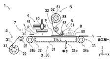
図1は、本発明を具現化する形態の一例の全体構成を示す側面図である。本発明に係る積層装置1は、第1セパレータ供給部2と、保持搬送部3と、電極板載置部4と、第2セパレータ供給部5と、押圧密着部6とを備えて構成されている。この積層装置1は、第1のセパレータ(つまり、下セパレータ)S1を供給しながらその上に電極板Pを載置し、さらにその上から第2のセパレータ(つまり、上セパレータ)S2を供給しながら重ね合わせることで、第1のセパレータS1と第2のセパレータS2との間に電極板Pが挟みまれた状態で互いに押圧され密着した積層状態となるように貼り合わせるものである。第1のセパレータS1及び第2のセパレータS2は、通液性があり、ひいては通気性もある。
FIG. 1 is a side view showing the overall configuration of an example of a form embodying the present invention. The
第1セパレータ供給部2は、第1のセパレータS1を供給するものである。具体的には、第1セパレータ供給部2は、供給リール21と、巻出器22とを含んで構成されている。
The first
供給リール21は、長尺の第1のセパレータS1が巻き付けられたものである。具体的には、供給リール21は、長尺の第1のセパレータS1の幅方向に延びた円筒状のシャフトで構成されている。
The
巻出器22は、供給リール21を回転させて長尺の第1のセパレータS1を引き出すものである。具体的には、巻出器22は、サーボモータにより能動的に供給リール21を回転させるものや、パウダークラッチと呼ばれるクラッチ機構により張力を調整しつつ受動的に供給リール21を回転させるものが例示できる。
The
第1セパレータ供給部2には、必要に応じて、供給される第1のセパレータにしわや弛みが発生するのを防ぐ手段である、サポートローラ25や、張力調整機構(例えば、エアダンサーや押さえローラなど:不図示)などを備えた構成としても良い。
The first
保持搬送部3は、第1のセパレータS1の下面に吸着力を作用させて当該第1のセパレータS1を保持しつつ搬送するものである。
The holding and
具体的には、保持搬送部3は、サクションコンベア30にて具現化することができる。サクションコンベア30は、バキュームコンベアとも呼ばれ、サクションチャンバー31と、サクションベルト32と、回転駆動機構33と、負圧発生器(不図示)とを含んで構成されている。
Specifically, the holding and conveying
サクションチャンバー31は、上部に開口部31hが設けられた筐体により構成されており、筐体の側面又は下面には吸引ポート31pが設けられている。開口部31hは、第1のセパレータS1に電極板Pが載置され、後述する押圧密着部6で第2のセパレータS2と押圧・密着されるまでの区間ないし加熱溶着部8で加熱・溶着されるまでの区間の、第1のセパレータS1の幅方向に亘る領域において、筐体上面を大きくくり抜いたものや、筐体上面に多数の貫通孔や貫通溝を設けたものが例示できる。吸引ポート31pは、外部の負圧発生器と接続されている。そのため、サクションチャンバー31では、開口部31hから筐体内に大気が吸い込まれ、吸い込まれた大気は吸引ポート31pを通じて筐体外へ排出される。負圧発生器(不図示)は、ブロワ、エジェクタ、真空ポンプなどを用いて構成することができる。
The
サクションベルト32は、その上面と第1のセパレータS1の下面と直接触れ合い、接触した部分に吸着力を作用させ、その吸着力が作用した状態で所定の方向vに移動することで、第1のセパレータS1を所定の方向vに搬送するものである。具体的には、サクションベルト32は、表裏面を貫通する通気開口部32hが設けられた無限軌道ベルトで構成されており、回転駆動機構33により予め規定された無限軌道を回転しながら移動する。サクションベルト32の具体例としては、ゴム、樹脂、薄い金属などの可撓性材料からなる平ベルトに多数の貫通孔を設けたものが例示できる。
The
サクションベルト32の通気開口部32h(詳細は後述する)は、サクションベルト32がサクションチャンバー31の開口部31hに覆い被さっている区間にあるときは、サクションチャンバー31の筐体内部と連通する状態(つまり、負圧状態)となり、それ以外の区間にあるときは、大気と連通する状態(つまり、大気圧状態)となる。
When the
回転駆動機構33は、サクションベルト32を予め規定された無限軌道にて所定の方向vに回転させるものである。より具体的には、回転駆動機構33は、1組の回転ローラ34a,34bと、回転ローラ34a,34bの少なくとも一方を回転駆動させる駆動モータ(不図示)を含んで構成されている。さらに、各回転ローラ34a,34bは、サクションベルト32がサクションチャンバー31の開口部31hに覆い被さりつつ横切るように配置されている。
The
サクションコンベア30は、第1セパレータS1の下面とサクションベルト32の上面とが接触する区間の内、サクションベルト32の下方にサクションチャンバー31の開口部31hが配置された区間Lにおいて、サクションベルト32の通気開口部32hとサクションチャンバー31の筐体内部の空間が負圧状態となる。この区間Lにおいて、第1のセパレータS1の下面には吸着力が作用している。そのため、サクションベルト32にて第1のセパレータS1を保持しつつ搬送することができる。
The
なお、サクションコンベア30は、所定の送り量ずつ搬送/停止を繰り返す定寸送りや、一定速度で駆動し続ける連続送りにて、搬送を行う。
Note that the
電極板載置部4は、保持搬送部3にて保持された第1のセパレータS1の上面に電極板Pを載置するものである。
具体的には、電極板載置部4は、搬送ロボット40と、その先端に取り付けた移載プレート41又は移載ハンドなどを備えている。
搬送ロボット40は、移載プレートをXYZ方向に移動させるものである。
移載プレート41は、下面側が電極板Pの上面と接触し、接触部分を負圧吸引するなどして電極板Pを保持したり、吸引解除にて保持解除するものである。より具体的には、移載プレート41は、下面側が平坦な板材に負圧吸引のための細溝または細孔が備えられ、これら細溝または細孔は、不図示の切替バルブなどを介して負圧発生源、圧空源、大気と連通する構成をしている。
The electrode
Specifically, the electrode
The
The
電極板載置部4は、次の様な動作を搬送ロボット40にさせることで、電極板Pを載置する。例えば、サクションコンベア30が定寸送りの場合、静止しているサクションベルト上に移載プレート41を下降させる。或いは、サクションコンベア30が連続送りの場合、移載プレート41を移動しているサクションベルト32の移動速度に同期してX方向に移動させつつ下降させる。
The electrode
このとき、第1のセパレータS1が通気性を有するため、電極板Pも負圧吸引される。 At this time, since the first separator S1 has air permeability, the electrode plate P is also sucked with negative pressure.
第2セパレータ供給部5は、第1のセパレータS1とは別の第2のセパレータS2を供給するものである。具体的には、第2セパレータ供給部5は、供給リール51と、巻出器52とを含んで構成されている。また、必要に応じて、折り返しローラ55や、張力調整機構などを備えた構成としても良い。なお、各構成は、第1セパレータ供給部2のそれらと同様の構成とすることができ、詳細な説明は省略する。
The second
押圧密着部6は、第1のセパレータS1及び第2のセパレータS2の搬送ラインを挟むように保持搬送部3と対向配置されており、第1のセパレータS1と第2のセパレータS2の間に電極板Pが挟まれた状態で当該第1のセパレータS1と当該第2のセパレータS2とを押圧して密着させるものである。
The
具体的には、押圧密着部6は、回転ローラ61と、ローラ押付部62とを含んで構成されている。
Specifically, the
回転ローラ61は、第2のセパレータS2の上面と接触しつつ、第1セパレータS1ないし第2のセパレータS2の搬送に伴って回転するものである。ローラ押付部62は、第1セパレータS1ないし第2のセパレータS2を搬送させる間、回転ローラ61をサクションコンベア30のサクションベルト32に向けて押圧するものである。
The rotating
本発明に係る積層装置1は、この様な構成をしているため、第1のセパレータS1の下面に吸着力を作用させつつ、第1のセパレータS1の上面とその上に貼り付けた電極板に対して吸着力を作用させたまま、さらにその上から第2のセパレータS2タを貼り付けることができる。その結果、第1のセパレータS1上に載置された電極板を位置ズレさせることなく、さらにその上から第2のセパレータS2を貼合せることができる。
Since the
[サクションベルトの通気開口部]
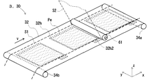
図2は、本発明を具現化する形態の一例の要部を示す斜視図であり、サクションベルト32に設けられた通気開口部32hの具体的な配置例が図示されている。
[Ventilation opening of suction belt]
FIG. 2 is a perspective view showing a main part of an example embodying the present invention, and a specific arrangement example of the
通気開口部32hは、第1のセパレータS1に電極板Pが載置される領域(つまり、電極板の外周端部Peの配置位置で囲まれた内側の領域)ないし、それよりも多少広い目の領域(つまり、外側の領域)に、多数の貫通孔や貫通溝が設けられている。そして、通気開口部32hの下方に、サクションチャンバー31の開口部31hが配置されている。
The
特に、開口部31hならびにサクションベルト32の通気開口部32hが、第1のセパレータS1の上面に載置される電極板Pの外周縁部Peよりも外側に配置されている方が、電極板Pの外周縁部Peにまで吸着力が作用するため、外周端部Peの剥離に起因したしわや折れ曲がりの発生を防ぐことができ、より好ましいと言える。
In particular, the electrode plate P is such that the
但し、外周端部Peの剥離が懸念されない程度であれば、保持搬送部3において、サクションチャンバー31の筐体上部に設けられた開口部31hならびにサクションベルト32の通気開口部32hは、第1のセパレータS1の上面に載置される電極板Pの外周縁部Peと同じ位置よりも、内側のみに配置されていても良い。
However, as long as there is no concern about peeling of the outer peripheral end Pe, the
[別の形態]
なお、電極板には、第1のセパレータS1の幅方向よりも外側に突出した集電部が備えられているので、図2に示す様に、サクションベルト32には、集電部が載置される領域に、通気開口部32h2を備えておくことが好ましい。この場合、サクションチャンバー31の開口部31hは、第1のセパレータS1端部よりも集電部側の幅方向に広幅としておく。もしくは、集電部の突出した幅部分を独立して負圧吸引する個別チャンバーを備えた構成としても良い。そして、通気開口部32h2における負圧吸引力を、通気開口部32hにおける負圧吸引力よりも強く設定しておく。そうすることで、電極板Pの集電部が、サクションベルト32と密着状態となり、押圧密着部6を通過する際に折れ曲がったり、しわが発生したりすることを防ぐことができる。
[Another form]
Since the electrode plate is provided with a current collecting portion that protrudes outward from the width direction of the first separator S1, the current collecting portion is placed on the
[別の形態]
上述では、押圧密着部6の一類型として、回転ローラ61とローラ押付部62を含んで構成されたものを用い、全面を押圧して密着させる形態を例示した。
[Another form]
In the above description, as a type of the
しかし、この様な構成に限定されず、1つ又は複数のブレード、エアナイフ、スポンジロール、ブラシロール、拍車(スパー:spur)等、又はこれらを組み合わせたものにより押圧密着部を構成しても良い。そして、これら押圧密着部を構成する上記部品は、幅方向の全長にわたって均等な押し付け力が作用するように接触させても良いし、ストライプ状に間引きされた状態、幅方向の左端・中央・右端のみ、幅方向の左端・右端のみを押さえ付けるなどで接触させても良く、適宜設定すれば良い。 However, the present invention is not limited to such a configuration, and the pressing contact portion may be configured by one or a plurality of blades, an air knife, a sponge roll, a brush roll, a spur, or a combination thereof. . And, the above-mentioned parts constituting these press-contacting portions may be brought into contact with each other so that an even pressing force acts over the entire length in the width direction, or are thinned out in a stripe shape, left end, center, right end in the width direction However, they may be brought into contact by pressing only the left and right ends in the width direction, and may be set appropriately.
[別の形態]
本発明を具現化する上では、上述の構成に加え、静電気発生部7を備えた構成としても良い。静電気発生部7は、第1セパレータ供給部2から供給された第1のセパレータS1の上面に静電気を帯電させるものである。
[Another form]
In embodying the present invention, in addition to the above-described configuration, a configuration including the static
具体的には、静電気発生部7は、プラス又はマイナスに帯電させたエアを、第1のセパレータS1に向けて吹き付けるものが例示できる。第1のセパレータS1は、上面がプラス又はマイナスに帯電した状態で、サクションコンベアにて搬送される。このとき、セパレータは絶縁性の材料であれば、上面が帯電した状態で電極板Pが載置される。この際、第1のセパレータS1の上面に載置された電極板Pの下面は、帯電した静電気の力により吸着力が増すため、位置ズレなどを防ぐ効果を奏する。
Specifically, the static
また、第1のセパレータS1の通気性が乏しい場合であっても、第1のセパレータS1の上面に載置された電極板Pの下面には、吸着力が作用するため、第2のセパレータS2を近づけ、押圧して密着させる際に、位置ズレなどを防ぐ効果を奏する。 Even if the air permeability of the first separator S1 is poor, the adsorption force acts on the lower surface of the electrode plate P placed on the upper surface of the first separator S1, so that the second separator S2 When the two are brought close to each other and pressed to be brought into close contact with each other, an effect of preventing positional misalignment and the like is exhibited.
[別の形態]
上述では、保持搬送部3の一類型として、サクションコンベア30を備えた構成を例示して説明した。しかし、保持搬送部3はこの様な構成に限らず、平板のテーブルと、このテーブルに吸着力を作用/解除させる機構と、このテーブルをX方向に往復移動させる機構を備えた構成としても良い。つまり、上述の図1に示した区間Lに対応する区間おいて、第1のセパレータS1と平板のテーブルとの間に負圧吸引による吸着力を作用させてこのテーブルを下流側に移動させ、所定の寸法だけ搬送した後、搬送を停止させ、テーブルの負圧吸引による吸着力を解除する。そして、第1及び第2のセパレータの搬送が止まった状態で、テーブルのみを上流側に移動させて停止させる。そして再びテーブルに負圧吸引による吸着力を作用させ下流側へ移動させる。この動作を繰り返すことで、定寸送りによる搬送ができる。
[Another form]
In the above description, the configuration including the
なお、上述では、保持搬送部のサクションコンベア30や平板のテーブルは、負圧吸引により吸着力を作用させたり解除ができる構成を示したが、静電チャックを用いて、静電吸着による吸着力を作用させたり解除ができる構成としても良い。
In the above description, the
[別の形態]
本発明に係る積層装置は、上述の各構成に限らず、さらに加熱溶着部8を備えた構成としても良い。加熱溶着部8は、電極板Pが挟まれた状態で押圧され密着状態となった第1のセパレータS1と第2のセパレータS2を加熱して溶着させるものである。
[Another form]
The laminating apparatus according to the present invention is not limited to the above-described configurations, and may be configured to further include a
具体的には、定寸送りにて搬送されている場合、加熱溶着部8は、ヒータプレート80と、ヒータと、アクチュエータとを備えた構成としておく。ヒータプレート80は、サクションコンベア30と対向配置されており、第2のセパレータS2と直接触れ合い、第1のセパレータS1、第2のセパレータS2ならびに電極板Pを加熱し、それらを溶着させるものである。ヒータは、ヒータプレートを加熱するものである。具体的には、ヒータは、ヒータプレート内に埋め込まれたセラミックヒータなどで構成する。アクチュエータは、ヒータプレート80をサクションコンベア30側に近づけたり、離間したりするものである。
Specifically, in the case of being conveyed by fixed-size feeding, the
なお、連続送りにて搬送されている場合、加熱溶着部8は、ヒータを備えた回転ローラ又は表面が滑らかな非回転の部材とと、ローラ押さえ手段とを備えた構成としておく。ローラ押さえ手段は、回転ローラ又は非回転の部材を、サクションコンベア30側に押し付けるものである。
In addition, when it is conveyed by continuous feeding, the
本発明に係る積層装置は、加熱溶着部8を備えることで、その上流側で第1のセパレータS1上に載置された電極板を位置ズレさせることなく第2のセパレータS2とで挟んで密着状態にしておくことができ、その状態を保ったまま、第1のセパレータS1と第2のセパレータS2を加熱して溶着させることができる。
The laminating apparatus according to the present invention is provided with the
[別の形態]
本発明に係る積層装置は、上述の構成に限らず、図3に示す様な構成としても良い。
図3は、本発明を具現化する形態の別の一例の全体構成を示す側面図である。本発明に係る積層装置1Bは、上述した積層装置1の保持搬送部3とは異なる構成の、保持搬送部3Bを備えて構成されている。
[Another form]
The laminating apparatus according to the present invention is not limited to the above-described configuration, and may be configured as shown in FIG.
FIG. 3 is a side view showing the overall configuration of another example of a form embodying the present invention. The
保持搬送部3Bは、上述のサクションコンベア30とは異なる構成の、サクションコンベア30Bを備えて構成されている。サクションコンベア30は、区間Lにおいて内部が連通する1つのチャンバー構造をしているのに対し、サクションコンベア30Bは、上下流方向に区分けされたチャンバー群で構成されている。
The holding and conveying
例えば、電極板Pを載置する区間L1、電極板Pの搬送方向下流側で第2のセパレータS2越しに押圧密着部6で押圧される部分から上流側に電極板Pの搬送方向長さ相当の区間L2、加熱溶着部8と対向する区間L3に区分けし、それぞれ独立したチャンバーもしくは隔壁で区分けされたチャンバーとし、それぞれに吸引ポート31p1〜31p3を備え、それぞれ個別に圧力調整を行う。そうすれば、区間L1,L3に電極板Pが載置されていない状態でも、第2のセパレータS2を貼り合わせる際に、区間L2で第1のセパレータS1と電極板Pに作用する負圧吸引力が低下せず、位置ズレを防ぐことができる。
For example, the section L1 where the electrode plate P is placed, the length in the transport direction of the electrode plate P from the portion pressed by the
なお、区間L2は、押圧密着部6で押圧される部分から上流側に電極板Pの搬送方向と同じ長さでも良いし、多少短くても長くても良い。つまり、設定された区間L2での負圧吸引力が十分あり、電極板Pの端部PeがのセパレータS2越しに押圧密着部6で押圧された際に、電極板Pが位置ズレ等しない程度の負圧吸引力が作用する状態であれば良い。
The section L2 may be the same length as the conveying direction of the electrode plate P upstream from the portion pressed by the
[別の形態]
本発明に係る積層装置は、上述の構成に限らず、図4に示す様な構成を備えても良い。
図4は、本発明を具現化する形態のさらに別の一例の要部を示す側面図であり、上述の積層装置1とは異なる構成の、積層装置1Cの要部が示されている。積層装置1Cは、上述の積層装置1に加えて、第2セパレータ供給角度経路変更部9が備えられている。
[Another form]
The laminating apparatus according to the present invention is not limited to the above-described configuration, and may have a configuration as shown in FIG.
FIG. 4 is a side view showing a main part of still another example of a form embodying the present invention, and shows a main part of a laminating apparatus 1C having a configuration different from that of the
第2セパレータ供給経路変更部9は、第2のセパレータS2の搬送経路を、実線で示す位置ないし破線S2’で示す位置の間で変更するものである。具体的には、第2セパレータ供給経路変更部9は、第1サブローラ91、第2サブローラ92、サブローラ位置変更機構94を含んで構成されている。
The second separator supply path changing unit 9 changes the conveyance path of the second separator S2 between a position indicated by a solid line or a position indicated by a broken line S2 '. Specifically, the second separator supply path changing unit 9 includes a
第1サブローラ91は、折り返しローラ55と押圧密圧部6との間に配置されている。第2サブローラ92は、巻出器52と折り返しローラ55との間に配置されている。
The
サブローラ位置変更機構94は、サクションベルト32の駆動に連動して、第1サブローラ91と第2サブローラ92とを、共に上下方向に位置変更させるものである。例えば、サブローラ位置変更機構94は、電極板Pの端部Peが回転ローラ61により押圧されるタイミングを見計らって、第1サブローラ91と第2サブローラ92とを一体的に下方へ移動させ、第2セパレータS2を電極板Pに近づける。或いは、電極板Pの端部Peを検出するセンサーを備え、電極板Pの端部Peを検出したタイミングと、サクションベルト32の駆動速度に基づいて、サブローラ位置変更機構94の上下動を行う構成としても良い。
The sub-roller
この様な構成にしておくことで、電極板Pの搬送方向下流側にある端部に、押圧密着部6による押付力が作用される際に、電極板Pの上面から第2のセパレータS2を覆い被せるように近づけ、電極板Pが位置ズレしようとするのを未然に防ぐことができる。そして、電極板Pの上面に第2のセパレータS2が密着された後は、サブローラ位置変更機構94を上方に移動させておき、次の下降タイミングを待つ。以下、第1及び第2のセパレータS1,S2を搬送させながら、電極板Pの有無に同期させて、第2セパレータS2を下方に移動させて電極板Pに近づけたり、上方に移動させて待機状態としたりすることができる。その上、第1及び第2サブローラ91,92が同時に上下動するため、搬送される第2のセパレータS2の経路長を一定に保ちつつ、上記動作を行うことができる。よって、セパレータの搬送速度が上がっても、確実に第2のセパレータS2の搬送経路長を一定に保つことができるので、好ましい。
With such a configuration, when the pressing force by the
なお、上記構成に限らず、第1サブローラ91のみをサブローラ位置変更機構94にて上下動させる構成とし、第2サブローラ57を別個に移動制御したり、第2サブローラ57を省いて巻出器52の回転数を制御したりして、第2のセパレータS2の搬送経路長を一定に保つ構成にしても良い。
Not only the above-described configuration, but also the configuration in which only the
1 積層装置
2 第1セパレータ供給部
3 保持搬送部
4 電極板載置部
5 第2セパレータ供給部
6 押圧密着部
7 静電気発生部
8 加熱溶着部
21 供給リール
22 巻出器
25 サポートローラ
30 サクションコンベア
30B サクションコンベア
31 サクションチャンバー
31h 開口部
31p 吸引ポート
32 サクションベルト
32h 通気開口部
32h2 通気開口部(集電部吸引用)
33 回転駆動機構
34a,34b 回転ローラ
40 搬送ロボット
41 移載プレート
51 供給リール
52 巻出器
55 折り返しローラ
91 第1サブローラ
92 第2サブローラ
94 サブローラ上下動機構
61 回転ローラ
62 ローラ押付部
S1 第1のセパレータ
S2 第2のセパレータ
S2’ 第2のセパレータ(経路変更後の位置)
P 電極板
Pe 電極板の端部
L 区間
v 搬送方向
DESCRIPTION OF
33
P electrode plate Pe electrode plate edge L section v Conveying direction
Claims (8)
前記第1のセパレータの下面に吸着力を作用させて当該第1のセパレータを保持しつつ搬送する保持搬送部と、
前記保持搬送部にて保持された前記第1のセパレータの上面に電極板を載置する電極板載置部と、
通液性がある第2のセパレータを供給する第2セパレータ供給部と、
前記第1のセパレータと前記第2のセパレータを挟んで前記保持搬送部と対向配置された押圧密着部を備え、
前記第1のセパレータの上面に載置された前記電極板の下面に吸着力を作用させた状態で、前記第1のセパレータS1及び前記電極板に前記第2のセパレータを近づけ、押圧して密着させる、積層装置。 A first separator supply section for supplying a liquid-permeable first separator;
A holding and conveying unit that conveys the first separator while holding the first separator by applying an adsorption force to the lower surface of the first separator;
An electrode plate placement portion for placing an electrode plate on the upper surface of the first separator held by the holding conveyance portion;
A second separator supply section for supplying a liquid-permeable second separator;
A pressing contact portion disposed opposite to the holding and conveying portion with the first separator and the second separator interposed therebetween;
With the suction force acting on the lower surface of the electrode plate placed on the upper surface of the first separator, the second separator is brought close to and pressed against the first separator S1 and the electrode plate. Let the laminating device.
前記第1のセパレータの上面に載置される前記電極板の外周縁部よりも内側ないし外側の領域に、前記吸着力を作用させることを特徴とする、請求項1に記載の積層装置。 The holding and conveying unit is
2. The stacking apparatus according to claim 1, wherein the adsorption force is applied to a region inside or outside of an outer peripheral edge of the electrode plate placed on the upper surface of the first separator.
前記保持搬送部の上面と平行に配置された回転ローラと、
前記回転ローラを前記保持搬送部側に向けて押さえ付けるローラ押付部を備えた、
請求項1又は請求項2に記載の積層装置。 The pressing contact portion is
A rotating roller disposed parallel to the upper surface of the holding and conveying unit;
A roller pressing unit that presses the rotating roller toward the holding and conveying unit;
The laminating apparatus according to claim 1 or 2.
上面に開口部が設けられたサクションチャンバーと、
表裏面を貫通する通気開口部が設けられた無限軌道ベルトと、
前記サクションチャンバーの開口部を横切るように前記無限軌道ベルトを回転駆動させる回転駆動機構とを備え、
前記第1セパレータの下面と前記無限軌道ベルトの上面とが接触する区間において、前記無限軌道ベルトの通気開口部が負圧状態となることで、前記第1セパレータの下面および当該第1セパレータの上面に載置された前記電極板の下面に吸着力を作用させて当該第1セパレータを保持しつつ搬送することを特徴とする、請求項1〜4のいずれかに記載の積層装置。 The holding and conveying unit is
A suction chamber with an opening on the top surface;
An endless track belt provided with ventilation openings penetrating the front and back surfaces;
A rotational drive mechanism that rotationally drives the endless track belt across the opening of the suction chamber;
In a section where the lower surface of the first separator and the upper surface of the endless track belt are in contact with each other, the ventilation opening of the endless track belt is in a negative pressure state, so that the lower surface of the first separator and the upper surface of the first separator are The laminating apparatus according to any one of claims 1 to 4, wherein the first separator is transported while an adsorption force is applied to the lower surface of the electrode plate placed on the substrate.
前記保持搬送部は、前記集電部の下面にも吸着力を作用させることを特徴とする、
請求項1〜5のいずれかに記載の積層装置。 The electrode plate is provided with a current collector protruding outward from the width direction of the first separator,
The holding and conveying unit is configured to cause an adsorption force to act on the lower surface of the current collector,
The lamination apparatus according to any one of claims 1 to 5.
Priority Applications (1)
| Application Number | Priority Date | Filing Date | Title |
|---|---|---|---|
| JP2015030127A JP2016152178A (en) | 2015-02-19 | 2015-02-19 | Lamination device |
Applications Claiming Priority (1)
| Application Number | Priority Date | Filing Date | Title |
|---|---|---|---|
| JP2015030127A JP2016152178A (en) | 2015-02-19 | 2015-02-19 | Lamination device |
Publications (1)
| Publication Number | Publication Date |
|---|---|
| JP2016152178A true JP2016152178A (en) | 2016-08-22 |
Family
ID=56696672
Family Applications (1)
| Application Number | Title | Priority Date | Filing Date |
|---|---|---|---|
| JP2015030127A Pending JP2016152178A (en) | 2015-02-19 | 2015-02-19 | Lamination device |
Country Status (1)
| Country | Link |
|---|---|
| JP (1) | JP2016152178A (en) |
Cited By (8)
| Publication number | Priority date | Publication date | Assignee | Title |
|---|---|---|---|---|
| CN106785076A (en) * | 2016-12-30 | 2017-05-31 | 成都国珈星际固态锂电科技有限公司 | Pole piece positioning mechanism, lithium ion battery lamination device and lithium ion battery lamination method |
| JP2018125169A (en) * | 2017-02-01 | 2018-08-09 | 日産自動車株式会社 | Conveyance device for electrode sheet |
| JP2019139961A (en) * | 2018-02-09 | 2019-08-22 | 株式会社村田製作所 | Manufacturing installation of laminate electrode body |
| JP2019140075A (en) * | 2018-02-15 | 2019-08-22 | 株式会社村田製作所 | Manufacturing installation of laminate electrode body |
| CN110589595A (en) * | 2019-09-30 | 2019-12-20 | 东莞市泽源机械有限公司 | Rotary wheel type adhesive tape pasting mechanism for lithium battery |
| KR102142828B1 (en) * | 2020-03-13 | 2020-08-07 | 조성해 | Moving Device of Polishing Apparatus for PCB SUS Plate |
| JPWO2019188724A1 (en) * | 2018-03-30 | 2021-04-08 | 日本ゼオン株式会社 | Manufacturing equipment and manufacturing method for laminates for secondary batteries |
| CN113611912A (en) * | 2021-06-15 | 2021-11-05 | 万向一二三股份公司 | Laminated structure of electrode assembly, preparation method and electrochemical device |
Citations (10)
| Publication number | Priority date | Publication date | Assignee | Title |
|---|---|---|---|---|
| JP2001093533A (en) * | 1999-09-21 | 2001-04-06 | Mekatekku Kk | Device for manufacturing layered cell |
| JP2002270213A (en) * | 2001-03-14 | 2002-09-20 | Shimane Jidoki Kk | Take-up method and take-up device of band element for flat electronic component |
| JP2004262561A (en) * | 2003-02-28 | 2004-09-24 | Nippei Toyama Corp | Winding apparatus |
| JP2004327154A (en) * | 2003-04-23 | 2004-11-18 | Toyota Motor Corp | Secondary battery winding device |
| JP2005190777A (en) * | 2003-12-25 | 2005-07-14 | Toray Eng Co Ltd | Method and device for manufacturing secondary battery |
| JP2007329111A (en) * | 2006-06-09 | 2007-12-20 | Litcel Kk | Manufacturing method and manufacturing device of lithium ion cell, its manufacturing method as well as manufacturing device, and manufacturing method as well as manufacturing device of bagged electrode plate |
| JP2008204706A (en) * | 2007-02-19 | 2008-09-04 | Sony Corp | Layered nonaqueous electrolyte battery, its formation method, and lamination device |
| JP2012022813A (en) * | 2010-07-12 | 2012-02-02 | Toyota Motor Corp | Electrode winding device and method for manufacturing wound electrode body cell |
| JP2014186830A (en) * | 2013-03-22 | 2014-10-02 | Toyota Boshoku Corp | Method for placing sheet and method for manufacturing laminated battery |
| JP2016035915A (en) * | 2014-07-31 | 2016-03-17 | 株式会社村田製作所 | Apparatus for manufacturing polar plate package |
-
2015
- 2015-02-19 JP JP2015030127A patent/JP2016152178A/en active Pending
Patent Citations (10)
| Publication number | Priority date | Publication date | Assignee | Title |
|---|---|---|---|---|
| JP2001093533A (en) * | 1999-09-21 | 2001-04-06 | Mekatekku Kk | Device for manufacturing layered cell |
| JP2002270213A (en) * | 2001-03-14 | 2002-09-20 | Shimane Jidoki Kk | Take-up method and take-up device of band element for flat electronic component |
| JP2004262561A (en) * | 2003-02-28 | 2004-09-24 | Nippei Toyama Corp | Winding apparatus |
| JP2004327154A (en) * | 2003-04-23 | 2004-11-18 | Toyota Motor Corp | Secondary battery winding device |
| JP2005190777A (en) * | 2003-12-25 | 2005-07-14 | Toray Eng Co Ltd | Method and device for manufacturing secondary battery |
| JP2007329111A (en) * | 2006-06-09 | 2007-12-20 | Litcel Kk | Manufacturing method and manufacturing device of lithium ion cell, its manufacturing method as well as manufacturing device, and manufacturing method as well as manufacturing device of bagged electrode plate |
| JP2008204706A (en) * | 2007-02-19 | 2008-09-04 | Sony Corp | Layered nonaqueous electrolyte battery, its formation method, and lamination device |
| JP2012022813A (en) * | 2010-07-12 | 2012-02-02 | Toyota Motor Corp | Electrode winding device and method for manufacturing wound electrode body cell |
| JP2014186830A (en) * | 2013-03-22 | 2014-10-02 | Toyota Boshoku Corp | Method for placing sheet and method for manufacturing laminated battery |
| JP2016035915A (en) * | 2014-07-31 | 2016-03-17 | 株式会社村田製作所 | Apparatus for manufacturing polar plate package |
Cited By (13)
| Publication number | Priority date | Publication date | Assignee | Title |
|---|---|---|---|---|
| CN106785076A (en) * | 2016-12-30 | 2017-05-31 | 成都国珈星际固态锂电科技有限公司 | Pole piece positioning mechanism, lithium ion battery lamination device and lithium ion battery lamination method |
| CN106785076B (en) * | 2016-12-30 | 2019-08-20 | 成都国珈星际固态锂电科技有限公司 | Pole piece positioning mechanism, lithium ion battery lamination device and lithium ion battery lamination method |
| JP2018125169A (en) * | 2017-02-01 | 2018-08-09 | 日産自動車株式会社 | Conveyance device for electrode sheet |
| JP2019139961A (en) * | 2018-02-09 | 2019-08-22 | 株式会社村田製作所 | Manufacturing installation of laminate electrode body |
| JP7081192B2 (en) | 2018-02-09 | 2022-06-07 | 株式会社村田製作所 | Equipment for manufacturing laminated electrode bodies |
| JP7004158B2 (en) | 2018-02-15 | 2022-01-21 | 株式会社村田製作所 | Equipment for manufacturing laminated electrode bodies |
| JP2019140075A (en) * | 2018-02-15 | 2019-08-22 | 株式会社村田製作所 | Manufacturing installation of laminate electrode body |
| JPWO2019188724A1 (en) * | 2018-03-30 | 2021-04-08 | 日本ゼオン株式会社 | Manufacturing equipment and manufacturing method for laminates for secondary batteries |
| JP7287386B2 (en) | 2018-03-30 | 2023-06-06 | 日本ゼオン株式会社 | Apparatus and method for manufacturing laminate for secondary battery |
| US11791500B2 (en) | 2018-03-30 | 2023-10-17 | Zeon Corporation | Apparatus and method for manufacturing laminate for secondary battery |
| CN110589595A (en) * | 2019-09-30 | 2019-12-20 | 东莞市泽源机械有限公司 | Rotary wheel type adhesive tape pasting mechanism for lithium battery |
| KR102142828B1 (en) * | 2020-03-13 | 2020-08-07 | 조성해 | Moving Device of Polishing Apparatus for PCB SUS Plate |
| CN113611912A (en) * | 2021-06-15 | 2021-11-05 | 万向一二三股份公司 | Laminated structure of electrode assembly, preparation method and electrochemical device |
Similar Documents
| Publication | Publication Date | Title |
|---|---|---|
| JP2016152178A (en) | Lamination device | |
| JP5901135B2 (en) | Laminating apparatus and laminating method | |
| JP5775229B2 (en) | Device for sandwiching electrode plates with separator | |
| KR101577880B1 (en) | Separator conveying device and separator conveying method | |
| JP6022783B2 (en) | Manufacturing device and manufacturing method of bagging electrode | |
| JP5893461B2 (en) | Position detection apparatus and position detection method | |
| JP5706743B2 (en) | Laminating apparatus and laminating method | |
| JP5521861B2 (en) | Electrode laminator | |
| JP2012113994A (en) | Polar plate wrapping apparatus | |
| WO2021017351A1 (en) | Laminating machine | |
| KR101504859B1 (en) | Joining device and joining method | |
| JP2012221707A (en) | Device and method for conveying separator | |
| WO2020079991A1 (en) | Battery material lamination device | |
| JP5827027B2 (en) | Separator transport apparatus and separator transport method | |
| JP5992670B2 (en) | Sheet sticking device and sticking method | |
| JP5411602B2 (en) | Printing machine, printing method for breathable work, and printing method for carbon paper for fuel cell | |
| JP5881533B2 (en) | Sheet pasting device | |
| JP2005161782A (en) | Method and equipment for pasting film |
Legal Events
| Date | Code | Title | Description |
|---|---|---|---|
| A621 | Written request for application examination |
Free format text: JAPANESE INTERMEDIATE CODE: A621 Effective date: 20180104 |
|
| A131 | Notification of reasons for refusal |
Free format text: JAPANESE INTERMEDIATE CODE: A131 Effective date: 20181211 |
|
| A977 | Report on retrieval |
Free format text: JAPANESE INTERMEDIATE CODE: A971007 Effective date: 20181212 |
|
| A02 | Decision of refusal |
Free format text: JAPANESE INTERMEDIATE CODE: A02 Effective date: 20190606 |