JP2016150717A - Routing structure for vehicular harness - Google Patents
Routing structure for vehicular harness Download PDFInfo
- Publication number
- JP2016150717A JP2016150717A JP2015030392A JP2015030392A JP2016150717A JP 2016150717 A JP2016150717 A JP 2016150717A JP 2015030392 A JP2015030392 A JP 2015030392A JP 2015030392 A JP2015030392 A JP 2015030392A JP 2016150717 A JP2016150717 A JP 2016150717A
- Authority
- JP
- Japan
- Prior art keywords
- harness
- vehicle
- battery module
- power pack
- groove
- Prior art date
- Legal status (The legal status is an assumption and is not a legal conclusion. Google has not performed a legal analysis and makes no representation as to the accuracy of the status listed.)
- Granted
Links
Images


Abstract
Description
この発明は、車両用ハーネスの配索構造に係り、特にパワーパックと車載部品との電気的接続を行うハーネスを配索する車両用ハーネスの配索構造に関する。 The present invention relates to a vehicle harness wiring structure, and more particularly to a vehicle harness wiring structure for wiring a harness for electrical connection between a power pack and an in-vehicle component.
ハイブリッド車等の電動車両には、電源となるパワーパックが搭載される。
パワーパックは、ケース内に、電池モジュールを備えるとともに、インバータ又はDCDCコンバータ、若しくはその両方などの高電圧の電気部品を有するものである。
パワーパック周辺では、パワーパックと車載部品との電気的接続を行うハーネスが配索される。
このようなハーネスの配索構造としては、例えば、以下の先行技術文献がある。
A power pack serving as a power source is mounted on an electric vehicle such as a hybrid vehicle.
The power pack includes a battery module in a case and high-voltage electrical components such as an inverter and / or a DCDC converter.
In the vicinity of the power pack, a harness for electrically connecting the power pack and the in-vehicle component is routed.
Examples of such harness routing structures include the following prior art documents.
特許文献1に係るハイブリッド車両の駆動装置は、ジェネレータとジェネレータの後方でギヤケースとを備え、ギヤケースにケース側端子台を固定し、フロアパネルに車体側端子台を固定し、車体側端子台をケース側端子台に対して下方且つ後方に配置し、ギヤケースにはケーブル収容溝を形成するための補強リブを形成し、ケーブル収容溝にケース側端子台と車体側端子台とに接続される通電ケーブルを収容し、通電ケーブルの断線や損傷などを回避する構造である。 A driving device for a hybrid vehicle according to Patent Document 1 includes a generator and a gear case behind the generator, a case side terminal block is fixed to the gear case, a vehicle body side terminal block is fixed to a floor panel, and the vehicle body side terminal block is fixed to the case. Current-carrying cable that is arranged below and behind the side terminal block, has a reinforcing rib for forming a cable receiving groove in the gear case, and is connected to the case side terminal block and the vehicle body side terminal block in the cable receiving groove This is a structure that avoids disconnection or damage of the energizing cable.
ところが、従来、パワーパックが搭載されたハイブリッド車両等では、パワーパックの側面にハーネスが露出して配置されていることから、車両側方(車両左右方向)から強い衝撃エネルギ(外力)が作用した際に、パワーパックの側面と車両部品との間でハーネスが挟み込まれてしまい、ハーネスが損傷するという不都合があった。 However, in conventional hybrid vehicles equipped with a power pack, since a harness is exposed on the side of the power pack, strong impact energy (external force) is applied from the side of the vehicle (the vehicle left-right direction). In this case, the harness is sandwiched between the side surface of the power pack and the vehicle parts, and the harness is damaged.
そこで、この発明は、車両側方から強い衝撃エネルギが作用した場合でも、ハーネスの損傷を防止できる車両用ハーネスの配索構造を提供することにある。 SUMMARY OF THE INVENTION Accordingly, the present invention is to provide a wiring structure for a vehicle harness that can prevent damage to the harness even when strong impact energy is applied from the side of the vehicle.
この発明は、複数のユニットを上下方向に重ねて構成したパワーパックと、前記パワーパックの電力を車載部品へ供給するハーネスとを備える車両用ハーネスの配索構造において、前記上下方向で隣接したユニットに溝部を形成するとともに、前記溝部に前記ハーネスを這わせて配索したことを特徴とする。 The present invention relates to a vehicle harness routing structure comprising a power pack configured by stacking a plurality of units in the vertical direction and a harness for supplying the power of the power pack to on-vehicle components, and the units adjacent in the vertical direction A groove portion is formed in the wire, and the harness is routed along the groove portion.
この発明は、車両側方から強い衝撃エネルギが作用した場合でも、ハーネスの損傷を防止できる。 This invention can prevent damage to the harness even when strong impact energy is applied from the side of the vehicle.
この発明は、車両側方から強い衝撃エネルギが作用した場合でも、ハーネスの損傷を防止する目的を、上下方向で隣接したユニットに形成した溝部にハーネスを這わせて実現するものである。 In the present invention, even when strong impact energy is applied from the side of a vehicle, the object of preventing damage to the harness is realized by placing the harness in a groove formed in a unit adjacent in the vertical direction.
図1〜図6は、この発明の実施例を示すものである。
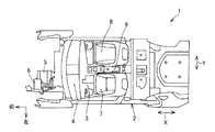
図1、図2に示すように、ハイブリッド車等の電動車両(以下「車両」という)1は、車体2と車体フロア3とインストルメントパネル4とを備える。
車体2の前部には、走行用モータ5と、走行用モータ5に接続されるインバータ6とが設置される。
車体フロア3の車室前部には、車両左右方向Yで左側シート7と右側シート8とが並んで設置されるとともに、左側シート7と右側シート8との間でパワーパック9が設置される。パワーパック9は、コンソールボックスで覆われる。
1 to 6 show an embodiment of the present invention.
As shown in FIGS. 1 and 2, an electric vehicle (hereinafter referred to as “vehicle”) 1 such as a hybrid vehicle includes a
A traveling
A
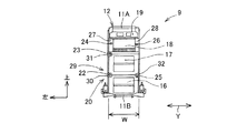
図3、図4に示すように、パワーパック9は、車両前後方向Xに延びる細長の長方体に形成され、前側から順次に、車両左右方向Yで略同じ幅Wに形成された第1〜第3部位10A〜10Cを備える。
第1部位10Aは、第1高さHIで、且つ第1長さL1に形成される。第2部位10Bは、第1高さH1よりも大きい第2高さH2で、且つ第1長さL1よりも小さい第2長さL2に形成される。第3部位10Cは、第2高さH2よりも大きい第3高さH3で、且つ第2長さL2よりも大きい第3長さL3に形成される。
第1部位10Aの後端部位と第2部位10Bの前端部位とは、上下方向で隣接して重なり合っている。
As shown in FIGS. 3 and 4, the
The
The rear end part of the
パワーパック9は、図3に示すように、例えば、上部ケース11Aと下部ケース11Bと後部ケース11Cとからなるケース12を備える。
ケース12内には、第1部位10Aで、ユニットとしての第1電池モジュール13が設置される。第1電池モジュール13は、複数のセルが一体的になって長方体に構成され、長手方向が車両前後方向Xに延びて配置される。
また、ケース12内には、第2部位10Bで、下方から上方へ順次に、ユニットとしてのジャンクションボックス(高電圧結線部)14と、サービスプラグ(高電圧遮断器)15とが設置される。ジャンクションボックス14は、箱体からなる。サービスプラグ15は、第3部位10C側で上部ケース11Cから上方へ突出して配置される。
さらに、ケース12内には、第3部位10Cで、下方から上方へ順次に、複数のユニットとしての第2電池モジュール16と第3電池モジュール17とDCDCコンバータ18とが上下方向で隣接して重ねられて設置され、また、DCDCコンバータ18の上方にバッテリコントローラ19が設置される。
第2電池モジュール16と第3電池モジュール17とは、それぞれ、複数のセルが一体的になって長方体に構成され、長手方向が車両前後方向Xに延び且つ上下方向で隣接して重ねられてパワーパック9を構成する。DCDCコンバータ18は、高電圧部品を構成する。
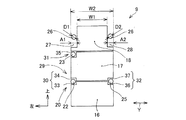
図6に示すように、後面視において、DCDCコンバータ18の幅W1は、第2電池モジュール16・第3電池モジュール17の幅W2よりも所定に狭く設定される。
As shown in FIG. 3, the
A
Further, in the
Further, in the
Each of the
As shown in FIG. 6, in the rear view, the width W1 of the
パワーパック9には、図3〜図6に示すように、パワーパック9の電力を車載部品(例えば、インバータ6)へ供給するように、車載部品に電気的に接続されるハーネス20が備えられる。
パワーパック9におけるハーネス20は、例えば、第1〜第6ハーネス21〜26からなる。
第1ハーネス21は、高電圧用であって、一端が第1電池モジュール13の上部前端に接続されるとともに他端がジャンクションボックス14に接続され、且つ第1電池モジュール13の上部に沿って配置される。
第2ハーネス22は、高電圧用であって、パワーパック9の左側面において、一端が第2電池モジュール16の上部後端に接続されるとともに他端がジャンクションボックス14に接続され、且つ第2電池モジュール16と第3電池モジュール17との接合部位の高さ位置で第2電池モジュール16と第3電池モジュール17とに沿って車両前後方向Xに配置される。
第3ハーネス23は、高電圧用であって、パワーパック9の左側面において、一端が第3電池モジュール17の上部後端に接続されるとともに他端がジャンクションボックス14に接続され、且つ第3電池モジュール17とDCDCコンバータ18との接合部位の高さ位置で第3電池モジュール17とDCDCコンバータ18とに沿って車両前後方向Xに配置される。
第4ハーネス24は、高電圧用であって、パワーパック9の左側面において、一端がバッテリコントローラ19の後端に接続されるとともに他端がジャンクションボックス14に接続され、且つDCDCコンバータ18の中間高さ位置でDCDCコンバータ18に沿って車両前後方向Xに配置される。
第5ハーネス25は、低電圧用(信号用)であって、パワーパック9の右側面において、一端がDCDCコンバータ18の後端に接続されるとともに他端がジャンクションボックス14に接続され、且つ第2電池モジュール16と第3電池モジュール17との接合部位の高さ位置で第2電池モジュール16と第3電池モジュール17とに沿って車両前後方向Xに配置される。
第6ハーネス26は、低電圧用(信号用)であって、パワーパック9の右側面において、一端がDCDCコンバータ18の後端に接続されるとともに他端がジャンクションボックス14に接続され、且つDCDCコンバータ18の中間高位置でDCDCコンバータ18に沿って車両前後方向Xに配置される。
また、ジャンクションボックス14には、他のハーネスを介してインバータ6が接続される。
As shown in FIGS. 3 to 6, the
The
The
The
The
The
The
The
The inverter 6 is connected to the
図6に示すように、第4ハーネス24は、DCDCコンバータ18の左側面に窪んで形成された左側隙間27に配置される。左側隙間27の幅A1は、第4ハーネス24の直径D1よりも大きく設定される。
また、第6ハーネス26は、DCDCコンバータ18の右側面に窪んで形成された右側隙間28に配置される。右側隙間28の幅A2は、第6ハーネス26の直径D2よりも大きく設定される。
なお、第4ハーネス24・第6ハーネス26は、左側隙間27・右側隙間28内に収容して配置されることにより、パワーパック9の車両左右方向Yの両側面から露出しない。
As shown in FIG. 6, the
Further, the
The
この実施例において、上下方向で隣接したユニットとしての第2電池モジュール16と第3電池モジュール17とDCDCコンバータ18とには、溝部29が形成される。
溝部29は、例えば、図5、図6に示すように、第1〜第3溝部30〜32からなる。 第1溝部30は、パワーパック9の左側面において、第2電池モジュール16と第3電池モジュール17との接合部位の高さ位置に形成される。第1溝部30は、第2電池モジュール16の左上部に断面L字形状に形成された第1切欠溝33と、第3電池モジュール17の左下部に断面逆L字形状に形成された第2切欠溝34とにより、車両左方に開口するように形成される。また、第1溝部30は、第2ハーネス22を収容可能な形状に形成される。
第1溝部30には、第2ハーネス22が収容されて這うように配索される。
第2溝部31は、パワーパック9の左側面において、第3電池モジュール17とDCDCコンバータ18とが接合する部位の高さ位置に形成される。第2溝部31は、第2電池モジュール16の左下部に断面L字形状に形成した第3切欠溝35と、DCDCコンバータ18の下部壁とにより、車両左方に開口するように形成される。また、第2溝部31は、第3ハーネス23を収容可能な形状に形成される。
第2溝部31には、第3ハーネス23が収容されて這うように配索される。
第3溝部32は、パワーパック9の右側面において、第2電池モジュール16と第3電池モジュール17とが接合する部位の高さ位置に形成される。第3溝部32は、第2電池モジュール16の右上部に断面L字形状に形成された第4切欠溝36と、第3電池モジュール17の右下部に断面逆L字形状に形成された第5切欠溝37とにより、車両右方に開口するように形成される。また、第3溝部32は、第5ハーネス25を収容可能な形状に形成される。
第3溝部32には、第5ハーネス25が収容されて這うように配索される。
In this embodiment, a
The
In the
The
In the
The
In the
このようなハーネス配索構造において、第2ハーネス22を第1溝部30に収容し、第3ハーネス23を第2溝部31に収容し、第5ハーネス25を第3溝部32に収容することにより、ハーネス22、23、25をパワーパック9の左右の側面から露出して配置することがなくなり、これにより、パワーパック9周辺のハーネス配索の最適化を可能にするとともに、車両側方(車両左右方向)から強い衝撃エネルギ(外力)が作用した場合でも、ハーネス22、23、25が車両部品(例えば、シートヒンジ)に挟み込まれることがなくなり、その時のハーネス22、23、25ヘの衝撃エネルギを緩和してハーネス22、23、25の損傷を防止することができる。
また、図5、図6に示すように、パワーパック9の左側面に高圧用のハーネス22、23、24をまとめて配置するとともに、パワーパック9の右側面には低圧用(信号用)のハーネス25、26をまとめて配置したことにより、高圧用のハーネス22、23、24と低圧用(信号用)のハーネス25、26とを切り離すことができ、ノイズ(電気)の影響をなくすことが可能となり、さらに、低圧用(信号用)のハーネス25、26からのノイズ(電気)の影響を高圧用のハーネス22、23、24に伝播させないようにすることができる。
さらに、ハーネス22、23、25がパワーパック9周辺で露出しないことから、パワーパック9の横幅の縮小化を図ることができる。
また、発熱しやすいDCDCコンバータ18を第3電池モジュール17の上方に設置したことにより、第3電池モジュール17の加熱を低減して、第3電池モジュール17の寿命を長くすることができる。
更に、第2電池モジュール16・第3電池モジュール17の固定構造とDCDCコンバータ18の固定構造とを共通化し、部品点数の削減を図ることができる。
In such a harness routing structure, the
Further, as shown in FIGS. 5 and 6, high-voltage harnesses 22, 23, and 24 are collectively arranged on the left side surface of the
Furthermore, since the
In addition, by installing the
Furthermore, the fixing structure of the
この発明に係るハーネス配索構造を、各種車両に適用可能である。 The harness routing structure according to the present invention can be applied to various vehicles.
1 車両
2 車体
3 車体フロア
4 インストルメントパネル
5 走行用モータ
9 パワーパック
10A〜10C 電池パックの第1〜第3部位
12 ケース
13 第1電池モジュール
14 ジャンクションボックス
15 サービスプラグ
16 第2電池モジュール
17 第3電池モジュール
18 DCDCコンバータ
19 バッテリコントローラ
20 ハーネス
21〜26 第1〜第6ハーネス
27 左側隙間
28 右側隙間
29 溝部
30〜32 第1〜第3溝部
DESCRIPTION OF SYMBOLS 1
Claims (1)
Priority Applications (1)
| Application Number | Priority Date | Filing Date | Title |
|---|---|---|---|
| JP2015030392A JP6520190B2 (en) | 2015-02-19 | 2015-02-19 | Wiring structure of vehicle harness |
Applications Claiming Priority (1)
| Application Number | Priority Date | Filing Date | Title |
|---|---|---|---|
| JP2015030392A JP6520190B2 (en) | 2015-02-19 | 2015-02-19 | Wiring structure of vehicle harness |
Publications (2)
| Publication Number | Publication Date |
|---|---|
| JP2016150717A true JP2016150717A (en) | 2016-08-22 |
| JP6520190B2 JP6520190B2 (en) | 2019-05-29 |
Family
ID=56695961
Family Applications (1)
| Application Number | Title | Priority Date | Filing Date |
|---|---|---|---|
| JP2015030392A Active JP6520190B2 (en) | 2015-02-19 | 2015-02-19 | Wiring structure of vehicle harness |
Country Status (1)
| Country | Link |
|---|---|
| JP (1) | JP6520190B2 (en) |
Cited By (2)
| Publication number | Priority date | Publication date | Assignee | Title |
|---|---|---|---|---|
| CN110861480A (en) * | 2018-08-10 | 2020-03-06 | 丰田自动车株式会社 | Vehicle front structure |
| DE102019103571A1 (en) * | 2019-02-13 | 2020-08-13 | Dr. Ing. H.C. F. Porsche Aktiengesellschaft | Method for assembling an underbody battery of a motor vehicle and an underbody battery for a motor vehicle |
Citations (7)
| Publication number | Priority date | Publication date | Assignee | Title |
|---|---|---|---|---|
| JP2005104387A (en) * | 2003-10-01 | 2005-04-21 | Fuji Heavy Ind Ltd | Drive of hybrid vehicle |
| JP2007069801A (en) * | 2005-09-08 | 2007-03-22 | Toyota Motor Corp | Structure of power supply to be mounted on vehicle |
| JP2007137329A (en) * | 2005-11-21 | 2007-06-07 | Toyota Motor Corp | Harness routing structure |
| JP2007299593A (en) * | 2006-04-28 | 2007-11-15 | Toyota Motor Corp | Vehicle mounting structure of power source device |
| JP2009292356A (en) * | 2008-06-06 | 2009-12-17 | Honda Motor Co Ltd | Vehicle body structure of fuel-cell vehicle |
| US20100163322A1 (en) * | 2008-12-18 | 2010-07-01 | Ferrari S.P.A. | Method of arranging an electric accumulating system close to a platform of a vehicle and hybrid propulsion vehicle |
| JP2012190808A (en) * | 2012-05-09 | 2012-10-04 | Toyota Motor Corp | Power storage device unit |
-
2015
- 2015-02-19 JP JP2015030392A patent/JP6520190B2/en active Active
Patent Citations (7)
| Publication number | Priority date | Publication date | Assignee | Title |
|---|---|---|---|---|
| JP2005104387A (en) * | 2003-10-01 | 2005-04-21 | Fuji Heavy Ind Ltd | Drive of hybrid vehicle |
| JP2007069801A (en) * | 2005-09-08 | 2007-03-22 | Toyota Motor Corp | Structure of power supply to be mounted on vehicle |
| JP2007137329A (en) * | 2005-11-21 | 2007-06-07 | Toyota Motor Corp | Harness routing structure |
| JP2007299593A (en) * | 2006-04-28 | 2007-11-15 | Toyota Motor Corp | Vehicle mounting structure of power source device |
| JP2009292356A (en) * | 2008-06-06 | 2009-12-17 | Honda Motor Co Ltd | Vehicle body structure of fuel-cell vehicle |
| US20100163322A1 (en) * | 2008-12-18 | 2010-07-01 | Ferrari S.P.A. | Method of arranging an electric accumulating system close to a platform of a vehicle and hybrid propulsion vehicle |
| JP2012190808A (en) * | 2012-05-09 | 2012-10-04 | Toyota Motor Corp | Power storage device unit |
Cited By (2)
| Publication number | Priority date | Publication date | Assignee | Title |
|---|---|---|---|---|
| CN110861480A (en) * | 2018-08-10 | 2020-03-06 | 丰田自动车株式会社 | Vehicle front structure |
| DE102019103571A1 (en) * | 2019-02-13 | 2020-08-13 | Dr. Ing. H.C. F. Porsche Aktiengesellschaft | Method for assembling an underbody battery of a motor vehicle and an underbody battery for a motor vehicle |
Also Published As
| Publication number | Publication date |
|---|---|
| JP6520190B2 (en) | 2019-05-29 |
Similar Documents
| Publication | Publication Date | Title |
|---|---|---|
| WO2014034377A1 (en) | High-voltage harness connection structure for electric vehicle | |
| CN101312855B (en) | Harness routing structure | |
| US20180370384A1 (en) | Mounting structure for high-voltage control equipment unit | |
| JP6419123B2 (en) | Power equipment unit and vehicle | |
| JP5656020B2 (en) | High-voltage cable routing structure for electric vehicles | |
| JP2017193299A (en) | Battery-mounting structure for vehicle | |
| JP2017140991A (en) | vehicle | |
| JP2017140992A (en) | vehicle | |
| JP4650041B2 (en) | Power supply | |
| JP2019097360A (en) | Power supply system | |
| US20160006147A1 (en) | Cable connecting structure of battery pack | |
| JP2007317400A (en) | Battery pack | |
| JP7302718B2 (en) | Wiring member and arrangement structure of wiring member | |
| JP7176939B2 (en) | Power supply unit | |
| JP5660111B2 (en) | Cable routing structure in the motor room of an electric vehicle | |
| JP6520190B2 (en) | Wiring structure of vehicle harness | |
| JP6688851B2 (en) | vehicle | |
| JP2015071397A (en) | Wiring harness wiring structure for electric vehicle | |
| JP2014097727A (en) | Wiring structure of high voltage cable for vehicle | |
| WO2014045708A1 (en) | Vehicle-mounted power unit | |
| WO2020137472A1 (en) | Wire harness assembly and wire harness assembly mounting structure | |
| JP7345730B2 (en) | Harness arrangement structure | |
| US11766924B2 (en) | Power supply apparatus and vehicle | |
| JP5853572B2 (en) | Battery pack for vehicles | |
| JP6291868B2 (en) | Inverter wiring structure |
Legal Events
| Date | Code | Title | Description |
|---|---|---|---|
| RD02 | Notification of acceptance of power of attorney |
Free format text: JAPANESE INTERMEDIATE CODE: A7422 Effective date: 20170601 |
|
| A621 | Written request for application examination |
Free format text: JAPANESE INTERMEDIATE CODE: A621 Effective date: 20170913 |
|
| RD01 | Notification of change of attorney |
Free format text: JAPANESE INTERMEDIATE CODE: A7421 Effective date: 20180130 |
|
| A977 | Report on retrieval |
Free format text: JAPANESE INTERMEDIATE CODE: A971007 Effective date: 20180614 |
|
| A131 | Notification of reasons for refusal |
Free format text: JAPANESE INTERMEDIATE CODE: A131 Effective date: 20180622 |
|
| A521 | Request for written amendment filed |
Free format text: JAPANESE INTERMEDIATE CODE: A523 Effective date: 20180730 |
|
| A131 | Notification of reasons for refusal |
Free format text: JAPANESE INTERMEDIATE CODE: A131 Effective date: 20190108 |
|
| A521 | Request for written amendment filed |
Free format text: JAPANESE INTERMEDIATE CODE: A523 Effective date: 20190130 |
|
| TRDD | Decision of grant or rejection written | ||
| A01 | Written decision to grant a patent or to grant a registration (utility model) |
Free format text: JAPANESE INTERMEDIATE CODE: A01 Effective date: 20190402 |
|
| A61 | First payment of annual fees (during grant procedure) |
Free format text: JAPANESE INTERMEDIATE CODE: A61 Effective date: 20190415 |
|
| R151 | Written notification of patent or utility model registration |
Ref document number: 6520190 Country of ref document: JP Free format text: JAPANESE INTERMEDIATE CODE: R151 |