JP2016150665A - Heavy-duty pneumatic tire - Google Patents
Heavy-duty pneumatic tire Download PDFInfo
- Publication number
- JP2016150665A JP2016150665A JP2015029170A JP2015029170A JP2016150665A JP 2016150665 A JP2016150665 A JP 2016150665A JP 2015029170 A JP2015029170 A JP 2015029170A JP 2015029170 A JP2015029170 A JP 2015029170A JP 2016150665 A JP2016150665 A JP 2016150665A
- Authority
- JP
- Japan
- Prior art keywords
- siping
- tire
- rib
- circumferential direction
- crown
- Prior art date
- Legal status (The legal status is an assumption and is not a legal conclusion. Google has not performed a legal analysis and makes no representation as to the accuracy of the status listed.)
- Granted
Links
- XLYOFNOQVPJJNP-UHFFFAOYSA-N water Substances O XLYOFNOQVPJJNP-UHFFFAOYSA-N 0.000 description 5
- 239000011324 bead Substances 0.000 description 4
- 239000011295 pitch Substances 0.000 description 4
- 229910000831 Steel Inorganic materials 0.000 description 3
- 230000000052 comparative effect Effects 0.000 description 3
- 239000010959 steel Substances 0.000 description 3
- 230000000694 effects Effects 0.000 description 2
- 238000002474 experimental method Methods 0.000 description 2
- 238000004519 manufacturing process Methods 0.000 description 2
- 239000000463 material Substances 0.000 description 2
- 239000010426 asphalt Substances 0.000 description 1
- 230000003247 decreasing effect Effects 0.000 description 1
- 230000006866 deterioration Effects 0.000 description 1
- 238000010008 shearing Methods 0.000 description 1
- 239000004575 stone Substances 0.000 description 1
- 238000010998 test method Methods 0.000 description 1
Images


Landscapes
- Tires In General (AREA)
Abstract
Description
本発明は、サイピングの形状を改善することにより、ウェット性能を確保しつつ、耐クラック性能を向上させた重荷重用空気入りタイヤに関する。 The present invention relates to a heavy-duty pneumatic tire having improved crack resistance while securing wet performance by improving the shape of siping.
近年、トラック、バス用等の重荷重用空気入りタイヤにあっては、ウェット路面でのグリップ力の向上及びクラックの発生を防止するため、図9に示されるように、リブaを横切るフルオープンタイプのサイピングsを設けることが提案されている。このサイピングsは、該サイピングsの両端に設けられる一対の端部タイバーt1と、この端部タイバーt1の内側かつ端部タイバーt1と離間して設けられる1以上の中間タイバーt2とを有する(下記特許文献1参照)。 In recent years, in heavy duty pneumatic tires for trucks, buses, etc., as shown in FIG. It has been proposed to provide a siping s. The siping s includes a pair of end tie bars t1 provided at both ends of the siping s, and one or more intermediate tie bars t2 provided inside the end tie bar t1 and spaced from the end tie bar t1 (described below). Patent Document 1).
このようなタイヤは、サイピング深さを減少させるタイバーt1、t2により、サイピングsの底部に生じがちなクラックや、サイピングを起点としたゴム欠け等が抑制される。また、タイバーの深さを限定することでウェット性能も確保される。 In such a tire, cracks that tend to occur at the bottom of the siping s, rubber chipping starting from siping, and the like are suppressed by the tie bars t1 and t2 that reduce the siping depth. Moreover, wet performance is also ensured by limiting the depth of a tie bar.
しかしながら、特許文献1には、中間タイバーt2の配設位置について具体的に言及されているものではない。発明者らは、種々の実験の結果、中間タイバーt2の配設位置を改善することにより、サイピング近傍のリブ剛性を高めて、さらにウェット性能を確保しつつクラックの発生を改善し得ることを見出した。
However,
本発明は、以上のような問題点に鑑み案出なされたもので、クラウンリブに設けられた特定形状のサイピングの中間の領域の全範囲に、中間タイバーを設けることを基本として、ウェット性能を確保しつつ、耐クラック性能を向上させる空気入りタイヤの提供を目的としている。 The present invention has been devised in view of the above-described problems, and provides wet performance based on the provision of intermediate tie bars in the entire range of the intermediate region of the specific shape of siping provided on the crown rib. It aims at providing the pneumatic tire which improves crack-proof performance, ensuring.
本発明は、トレッド部の中央部に、タイヤ周方向に連続してのびる少なくとも一本のクラウンリブを具えた重荷重用空気入りタイヤであって、前記クラウンリブには、0.4〜1.6mmの切り込み幅を有しかつ該クラウンリブを全幅に亘って横切るサイピングがタイヤ周方向に隔設され、前記サイピングは、その全長さ範囲でタイヤ軸方向に対する角度が15〜50度である第1サイピングを含み、前記第1サイピングは、前記角度がクラウンリブのリブ縁から該クラウンリブのタイヤ軸方向中間部側へ向けて漸増するとともに、前記第1サイピングは、タイヤ周方向長さを3等分したときの中間の領域の全範囲に、サイピングの深さを減少させる中間タイバーが設けられていることを特徴とする。 The present invention is a heavy duty pneumatic tire having at least one crown rib extending continuously in the tire circumferential direction at the center of the tread portion, wherein the crown rib has a thickness of 0.4 to 1.6 mm. A first siping having an incision width of about 1 to 50 degrees and an angle with respect to the tire axial direction of the siping across the entire width of the crown rib. In the first siping, the angle gradually increases from the rib edge of the crown rib toward the intermediate portion in the tire axial direction of the crown rib, and the first siping divides the tire circumferential length into three equal parts. An intermediate tie bar for reducing the depth of siping is provided over the entire range of the intermediate region.
本発明に係る重荷重用空気入りタイヤは、前記中間タイバーが、サイピングに沿った長さが6〜10mm、及びサイピングの最深部からの高さが2〜5mmであるのが望ましい。 In the heavy duty pneumatic tire according to the present invention, the intermediate tie bar preferably has a length along the siping of 6 to 10 mm and a height from the deepest portion of the siping of 2 to 5 mm.
本発明に係る重荷重用空気入りタイヤは、前記第1サイピングが、前記中間の領域での前記角度が30〜50度であるのが望ましい。 In the heavy duty pneumatic tire according to the present invention, it is preferable that the first siping has an angle of 30 to 50 degrees in the intermediate region.
本発明に係る重荷重用空気入りタイヤは、前記第1サイピングが、前記リブ縁からタイヤ軸方向内側にのびかつ前記中間タイバーとは離間した端部タイバーが設けられているのが望ましい。 In the heavy duty pneumatic tire according to the present invention, it is preferable that the first siping is provided with an end tie bar extending inward in the tire axial direction from the rib edge and separated from the intermediate tie bar.
本発明に係る重荷重用空気入りタイヤは、前記第1サイピングのタイヤ半径方向外端部に、切り込み幅が大きい拡幅部が設けられているのが望ましい。 In the heavy duty pneumatic tire according to the present invention, it is preferable that a widened portion having a large cut width is provided at an outer end portion in the tire radial direction of the first siping.
本発明に係る重荷重用空気入りタイヤは、前記クラウンリブには、全長さ範囲でタイヤ周方向に対して同じ向きにのびるS字状の前記第1サイピング、及び、タイヤ周方向に対して同じ向きにのびる一対の両側部と、該両側部とはタイヤ周方向に対して逆向きにのびかつ前記両側部間を継ぐ中央部とを含むクランク状サイピングが、タイヤ周方向に交互に設けられるのが望ましい。 In the heavy-duty pneumatic tire according to the present invention, the crown rib has the S-shaped first siping extending in the same direction with respect to the tire circumferential direction in the entire length range, and the same direction with respect to the tire circumferential direction. A crank-shaped siping including a pair of extending side portions and a center portion extending in the opposite direction to the tire circumferential direction and connecting between the both side portions is provided alternately in the tire circumferential direction. desirable.
本発明に係る重荷重用空気入りタイヤは、前記クラウンリブが、タイヤ赤道の両側に設けられた一対からなり、該クラウンリブのタイヤ赤道側の内側リブ縁は、タイヤ周方向にジグザグ状にのび、前記S字状の第1サイピングと内側リブ縁との交わり部は、該内側リブ縁のタイヤ赤道側の端点からタイヤ周方向に2〜10mm位置ずれしているのが望ましい。 In the heavy duty pneumatic tire according to the present invention, the crown rib is formed of a pair provided on both sides of the tire equator, and the inner rib edge on the tire equator side of the crown rib extends in a zigzag shape in the tire circumferential direction, It is desirable that the intersection of the S-shaped first siping and the inner rib edge is displaced by 2 to 10 mm in the tire circumferential direction from the end point on the tire equator side of the inner rib edge.
本発明の重荷重用空気入りタイヤのクラウンリブには、0.4〜1.6mmの切り込み幅を有しかつ該クラウンリブを全幅に亘って横切るサイピングがタイヤ周方向に隔設される。従って、路面の水膜がサイピング内に吸い上げられ除去されるため、ウェット性能が確保される。また、サイピングは、その全長さ範囲でタイヤ軸方向に対する角度が15〜50度である第1サイピングを含み、第1サイピングは、前記角度がクラウンリブのリブ縁からクラウンリブのタイヤ軸方向中間部側へ向けて漸減するとともに、第1サイピングは、タイヤ周方向長さを3等分したときの中間の領域の全範囲に、サイピングの深さを減少させる中間タイバーが設けられる。このようなサイピングを具えたタイヤは、サイピングの中間の領域の剛性を高めるとともに、該サイピングの開きを確実に抑制し、クラックの発生をより効果的に防止し得る。 The crown rib of the heavy duty pneumatic tire of the present invention is provided with sipings having a cut width of 0.4 to 1.6 mm and across the entire width of the crown rib in the tire circumferential direction. Accordingly, since the water film on the road surface is sucked up and removed in the siping, the wet performance is ensured. Further, the siping includes a first siping having an angle with respect to the tire axial direction of 15 to 50 degrees in the entire length range, and the first siping is an intermediate portion in the tire axial direction of the crown rib from the rib edge of the crown rib. In the first siping, an intermediate tie bar that reduces the depth of siping is provided in the entire range of the intermediate region when the tire circumferential length is equally divided into three. A tire having such a siping can increase the rigidity of an intermediate region of the siping and reliably suppress the opening of the siping, thereby preventing the occurrence of cracks more effectively.
以下、本発明の実施の一形態が図面に基づき説明される。
図1には、本実施形態の重荷重用空気入りタイヤ1の正規状態の右半分断面図が示されている。本明細書において、前記「正規状態」とは、タイヤが正規リム(図示せず)にリム組みされかつ正規内圧が充填された無負荷の状態とし、特に断りがない場合、タイヤ各部の寸法等は、この正規状態で測定された値である。
Hereinafter, an embodiment of the present invention will be described with reference to the drawings.
FIG. 1 shows a right half sectional view of a normal state of the heavy duty
前記「正規リム」とは、タイヤが基づいている規格を含む規格体系において、各規格がタイヤ毎に定めているリムであり、JATMAであれば"標準リム"、TRAであれば "Design Rim" 、ETRTOであれば "Measuring Rim"となる。また、前記「正規内圧」とは、タイヤが基づいている規格を含む規格体系において、各規格がタイヤ毎に定めている空気圧であり、JATMAであれば"最高空気圧"、TRAであれば表 "TIRE LOAD LIMITS AT VARIOUS COLD INFLATION PRESSURES" に記載の最大値、ETRTOであれば "INFLATION PRESSURE" とする。 The “regular rim” is a rim defined for each tire in the standard system including the standard on which the tire is based. “Standard Rim” for JATMA, “Design Rim” for TRA For ETRTO, "Measuring Rim". In addition, the “regular internal pressure” is an air pressure determined by each standard for each tire in the standard system including the standard on which the tire is based. TIRE LOAD LIMITS AT VARIOUS COLD INFLATION PRESSURES "Maximum value", ETRTO, "INFLATION PRESSURE".
本実施形態の重荷重用空気入りタイヤ(以下、単に「タイヤ」ということがある。)1は、トレッド部2からサイドウォール部3をへてビード部4のビードコア5に至るカーカス6と、このカーカス6の半径方向外側かつトレッド部2の内部に配された複数枚のベルトプライからなるベルト層7とを具える。
A heavy-duty pneumatic tire (hereinafter, simply referred to as “tire”) 1 according to the present embodiment includes a
前記カーカス6は、一対のビードコア5、5間をトロイド状に跨る本体部6aと、この本体部6aの両側に連なりかつ前記ビードコア5の回りでタイヤ軸方向内側から外側に折り返された折返し部6bとを有する少なくとも1枚(本実施形態では1枚)のカーカスプライ6Aからなる。前記カーカスプライ6Aは、例えばスチールからなるカーカスコードがタイヤ赤道C方向に対して例えば75〜90°の角度で配列されている。
The
前記ベルト層7は、本実施形態では、タイヤ半径方向に重ねられた合計4枚のベルトプライ7A〜7Dから構成され、例えば最もタイヤ軸方向幅が大きいベルトプライ7Bが、タイヤ半径方向内側から2層目に配置されている。ベルトプライ7A〜7Dは、スチールコードからなり、タイヤ赤道Cに対して15〜45°で傾きかつ互いに交差する少なくとも2枚のベルトプライが含まれる。
In the present embodiment, the
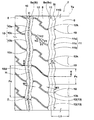
図1、図2に示されるように、本実施形態のトレッド部2には、タイヤ赤道C上を連続してのびるクラウン周方向溝10と、そのタイヤ軸方向両外側かつトレッド端Teのタイヤ軸方向内側を連続してのびる一対のショルダー周方向溝11とが形成される。従って、トレッド部2には、トレッド部2の中央部かつタイヤ赤道Cの両側に、クラウン周方向溝10とショルダー周方向溝11とで区分されかつタイヤ周方向に連続してのびる一対のクラウンリブ8と、ショルダー周方向溝11とトレッド端Teとで区分されかつタイヤ周方向に連続してのびる一対のショルダーリブ9とが設けられる。
As shown in FIGS. 1 and 2, the
なお、トレッド部2の中央部に形成されるクラウンリブ8は、最もタイヤ赤道Cの近くに設けられたリブを意味する。本実施形態では、クラウンリブ8がタイヤ赤道Cの両側に設けられるが、クラウンリブ8は、タイヤ赤道C上に設けられた1本のみからなるものでも良い。
In addition, the
本実施形態において、前記各周方向溝10、11は、いずれもタイヤ周方向にジグザグ状に屈曲しながらのびる。このような周方向溝10、11は、接地面の広い範囲から水を集めて排水することができるため、ウェット性能を大きく確保するのに役立つ。
In the present embodiment, each of the
クラウン周方向溝10は、タイヤ周方向に対して比較的小さい角度で一方に傾斜してのびる第1の傾斜部10aと、この第1の傾斜部10aとは逆の方向に傾斜してのびる第2の傾斜部10bとが交互に設けられる。また、本実施形態では、第1、第2の傾斜部10a、10bが交わるジグザグのコーナ部の谷側には、溝幅を増大させる平面視略三角形状の幅広部10cが設けられる。このようなジグザグ溝は、第1の傾斜部10a及び第2の傾斜部10bでは接地面の水膜を効果的に集め、また幅広部10cでは排水の抵抗を小さくできるため、ウェット性能が向上する。なお、図1、2に示されるように、本実施形態のクラウン周方向溝10の溝底面10Uには、略角柱状で隆起する石噛み防止用の隆起部Hがタイヤ周方向に隔設されている。
The crown
前記ショルダー周方向溝11も、クラウン周方向溝10と同様の構成であり、第1の傾斜部11aと、第2の傾斜部11bと、該第1、第2の傾斜部11a、11bが交わるジグザグのコーナ部の谷側に設けられた幅広部11cとを具える。
The shoulder
本実施形態のショルダー周方向溝11のジグザグピッチPsは、クラウン周方向溝10のジグザグピッチPcの45〜55%である。これにより、クラウン周方向溝10は、ショルダー周方向溝11よりも相対的に直線状に近づく。このようなクラウン周方向溝10は、ショルダー周方向溝11よりも排水抵抗が小さくなるため、タイヤ赤道側の高い接地圧を利用してウェット性能を向上させる。また、クラウンリブ8の周方向剛性も増大する結果、操縦安定性の向上にも役立つ。
The zigzag pitch Ps of the shoulder
前記各周方向溝10、11は、ウェット性能と操縦安定性能をバランスよく確保するために、その溝幅(溝の長手方向と直角な溝幅とする。)W1は、トレッド端Te、Te間のタイヤ軸方向距離であるトレッド幅TWの4.0〜8.0%の範囲が望ましい。同様に周方向溝10、11の溝深さD1(図3に示す)は、12〜16mmの範囲が望ましい。
Each of the
なお、「トレッド端Te」は、前記正規状態のタイヤに正規荷重を負荷してキャンバー角0度でトレッド部2を平面に接地させたときの最もタイヤ軸方向外側の接地端として定められる。また、前記「正規荷重」とは、タイヤが基づいている規格を含む規格体系において、各規格がタイヤ毎に定めている荷重であり、JATMAであれば最大負荷能力、TRAであれば表 "TIRE LOAD LIMITS AT VARIOUS COLD INFLATION PRESSURES" に記載の最大値、ETRTOであれば "LOAD CAPACITY"とする。
The “tread end Te” is defined as the outermost contact end in the tire axial direction when a normal load is applied to the tire in the normal state and the
前記周方向溝10、11のタイヤ周方向に対する傾斜角度θも、特に限定されるものではないが、ウェット性能と各リブ8、9の剛性をバランスよく確保する観点より、5〜25度の範囲が望ましい。
The inclination angle θ of the
さらに、本実施形態のような4リブパターンの場合、クラウン周方向溝10はタイヤ赤道C上をのびるのが望ましい。また、ショルダー周方向溝11の中心線11G(ジグザグの場合には振幅の中心線)とトレッド端Teとのタイヤ軸方向距離L1は、トレッド幅TWの17〜25%程度が望ましい。ただし、周方向溝10、11の配設位置はこのような態様に限定されるものではなく適宜変更することができる。
Furthermore, in the case of the 4-rib pattern as in the present embodiment, it is desirable that the
前記クラウンリブ8には、該クラウンリブ8を全幅に亘って横切るサイピング12がタイヤ周方向に隔設される。このようなサイピング12は、ウェット路面の水膜を吸い上げて周方向溝10、11へと排水できる。従って、リブパターンのウェット性能を向上させる。他方、本実施形態のショルダーリブ9には、このようなリブを全幅で横切るサイピングは設けられていない。
The
前記サイピング12は、サイピングの長手方向と直角な幅である切り込み幅W2(図4に示す)が0.4〜1.6mmで形成される必要がある。前記切り込み幅W2が1.6mmを超えると、該サイピング12近傍のリブ剛性が小さくなるため、その部分を起点としたクラックや欠け等が発生するおそれがある。逆に、前記切り込み幅W2が0.4mm未満であると、スムーズな排水が行えず、ウェット性能が悪化する。このような観点により、前記切り込み幅W2は、好ましくは0.6mm以上が望ましく、また、好ましくは1.4mm以下、さらに好ましくは1.2mm以下が望ましい。同様の観点より、前記サイピング12のリブ踏面からの最大深さD2(図3に示す)は、前記周方向溝の溝深さD1の好ましくは30%以上、より好ましくは40%以上が望ましく、また好ましくは90%以下、より好ましくは80%以下が望ましい。
The
また、図4に示されるように、サイピング12は、タイヤ軸方向に対する角度αが15〜50度である第1サイピング13を含んでいる。本実施形態の第1サイピング13は、その全長さ範囲でタイヤ周方向に対して同じ向きにのび、平面視がS字状の第1サイピング16(以下、単に「S字状サイピング16」と表示する場合がある。)を含んでいる。
Moreover, as FIG. 4 shows, the
第1サイピング13において、前記角度αは、サイピングの全長さ範囲で満たされている。前記角度αが50度を超えると、クラウンリブ8の横剛性が低下して操縦安定性が悪化する他、第1サイピング13の近傍でクラックやゴム欠け等の損傷が生じ易くなる。このような観点により、前記角度αは、より好ましくは45度以下が望ましい。逆に、前記角度αが15度未満であると、排水抵抗が大きくなり、ウェット性能が悪化する。このような観点より、前記角度αは、より好ましくは20度以上が望ましい。なお、第1サイピング13が、本実施形態のように曲線状をなす場合、前記角度αは、サイピングの中心線の接線の角度とする。
In the
また、第1サイピング13は、タイヤ軸方向に対する角度αが、クラウンリブ8のリブ縁8eから該クラウンリブ8のタイヤ軸方向の中間部側へ向けて漸増している。このような第1サイピング13は、その中間部側での排水をスムーズに行うことができる。また、直進時の制動力や駆動力が相対的に大きく作用するクラウンリブ8のリブ縁8e側では、軸方向のエッジ成分を有効に利用できる。従って、第1サイピング13は、ウェット性能や操縦安定性能を高く維持できる。また、相対的に剛性の小さいリブ縁8e近傍には、第1サイピング13の前記角度αを小さくすることにより、リブ縁8e近傍のリブ剛性を確保するとともに、相対的に剛性の大きいクラウンリブ8のタイヤ軸方向の中間部には、第1サイピング13の前記角度αを大きくすることにより、該第1サイピング13の周方向成分長さを大きくして、ウェット性能を向上しうる。
In the
図4及び図4のZ−Z断面である図5に示されるように、第1サイピング13は、タイヤ周方向長さLsを3等分したときの中間の領域Rcの少なくとも全範囲に、サイピングの深さを減少させる中間タイバー14が設けられている。第1のサイピング13の中間の領域Rcは、タイヤ周方向成分が大きく、旋回時の横力によって大きく開きやすい。しかし、中間タイバー14を設けることにより、中間の領域Rcの全範囲でサイピング深さが減じられ、ひいては旋回時でも中間の領域Rcでサイピングが大きく開くのが確実に抑制される。これにより、サイピング近傍でのクラックやゴム欠け等の発生が防止される。
As shown in FIG. 5 which is a ZZ cross-section of FIG. 4 and FIG. 4, the
また、前記中間タイバー14のタイヤ周方向長さLcが大きすぎると排水抵抗が大きくなりウェット性能が低下するおそれがある。このような観点より、前記中間タイバー14のタイヤ周方向長さLcと第1サイピング13のタイヤ周方向長さLsとの比Lc/Lsは、好ましくは40%以上が望ましく、また好ましくは50%以下が望ましい。
Further, if the length Lc in the tire circumferential direction of the
また、同様の観点より、中間タイバー14は、図4に示されるように、第1のサイピング13に沿った長さL2が、好ましくは5mm以上、より好ましくは6mm以上が望ましい。他方、中間タイバー14の前記長さL2は、大きすぎると排水抵抗が大きくなりウェット性能が低下する傾向があるため、好ましくは15mm以下が望ましい。同様の観点より、中間タイバー14の第1のサイピング13の最深部13sからの高さh1は、好ましくは2mm以上が望ましく、また好ましくは5mm以下が望ましい。なお、最深部13sは、リブ踏面と平行にのびている。
Further, from the same viewpoint, the
このように、本実施形態では、クラウンリブ8に形成される第1サイピング13の角度を規定するとともに、中間の領域Rcの全範囲に中間タイバー14を設けることで、排水がスムーズに行われるとともに、クラウンリブ8の剛性がバランスよく維持される。これにより、本発明のタイヤ1は、ウェット性能と耐クラック性能とがバランス良く向上する。
As described above, in the present embodiment, the angle of the
上記作用をより一層高めるために、第1サイピング13の中間の領域Rcでの前記角度αは、好ましくは30度以上、より好ましくは35度以上が望ましく、また好ましくは50度以下、より好ましくは45度以下が望ましい。上記作用をより一層高めるために、第1サイピング13の前記角度αの最大値と最小値との差は、好ましくは20〜30度の範囲で定められるのが望ましい。
In order to further enhance the above action, the angle α in the intermediate region Rc of the
また、図3及び図5に示されるように、本実施形態の第1サイピング13は、両側のリブ縁8e、8eからそれぞれタイヤ軸方向内側にのびる一対の端部タイバー15、15が設けられる。このような端部タイバー15は、とりわけ剛性の小さいリブ縁8e側のサイピングの底部の剛性を高め、かつ、大きな開きを抑えてクラックの発生を防止できる。しかも端部タイバー15は、中間タイバー14とは離間して設けられる。このような端部タイバー15は、排水空間を確保して、ウェット性能の悪化を防止できる。
As shown in FIGS. 3 and 5, the
なお、端部タイバー15の長さL3及び高さh2が過度に大きくなると、ウェット性能が悪化する傾向があり、逆に前記長さL3及び高さh2が小さくなると、リブ縁側での摩耗やゴム欠け等が生じるおそれがある。このような観点より、前記端部タイバー15のサイピングに沿った長さL3は、好ましくは2mm以上が望ましく、また好ましくは7mm以下が望ましい。同様に、端部タイバー15の第1のサイピング13の最深部13sからの高さh2は、好ましくは2mm以上が望ましく、また好ましくは5mm以下が望ましい。
When the length L3 and the height h2 of the
図6及び図2のY1、Y2断面である図7(a)、(b)に示されるように、第1サイピング13のタイヤ半径方向の外端部13Uには、切り込み幅が大きい拡幅部18が設けられる。このような第1のサイピング13は、排水量を大きく確保できるため、ウェット性能が向上する。また、拡幅部18が設けられることにより、駆動力や制動力による荷重が第1サイピング13の最深部13sでは小さくなるため、この部分に発生するクラック等を効果的に抑制することができる。また、摩耗によって拡幅部18が消失しても、踏面に新たに第1サイピング13の鋭利なエッジを出現させることができる。従って、長期に亘って優れたウェット性能が発揮され得る。本実施形態では、拡幅部18は、サイピング12の全ての外端部13Uに設けられている。これにより、上述の作用が効果的に高められる。
As shown in FIGS. 7A and 7B which are Y1 and Y2 cross sections of FIGS. 6 and 2, the widened
図7に示されるように、本実施形態の拡幅部18は、第1サイピング13の長手方向と直角な断面視において、リブ踏面からタイヤ半径方向内方にのびる一対の内向き面18aと、該内向き面18a、18aの内端から前記第1サイピング13にのびる底面18b、18bとからなる矩形状で形成される。前記一対の内向き面18aは、本実施形態では、踏面の法線方向にのびており、第1サイピング13からそれぞれ等距離で離間している。また、底面18bは、リブ踏面と平行な面で形成されている。ただし、拡幅部18は、このような態様に限定されるものではない。例えば、内向き面18aと外向き面18bとの交差部は、面取りされても良いし、内向き面18aと外向き面18bとが滑らかな円弧面で形成されても良い。
As shown in FIG. 7, the widened
前記拡幅部18の幅W3又は深さD3が小さくなると、排水空間が低下するおそれがあり、逆に前記幅W3又は深さD3が大きくなると、クラウンリブ8の剛性が低下するおそれがある。このような観点より、前記幅W3は、好ましくは2mm以上が望ましく、また好ましくは3mm以下が望ましい。同様に、拡幅部18の深さD3は、好ましくは1mm以上が望ましく、また好ましくは4mm以下が望ましい。
When the width W3 or the depth D3 of the widened
また、図4に示されるように、クラウンリブ8には、前記S字状サイピング16に加え、クランク状サイピング17が設けられる。
As shown in FIG. 4, the
前記クランク状サイピング17は、タイヤ周方向に対して同じ向きにのびる一対の両側部17aと、該両側部17aとはタイヤ周方向に対して逆向きにのびかつ前記両側部17a、17a間を継ぐ中央部17bとを含んで構成される。このようなクランク状サイピング17は、駆動時や制動時に大きなタイヤ周方向のせん断力が作用した場合でも、その中央部17bを介して向き合う陸部が互いに噛み合い、サイピングの大きな開きが抑制される。このため、クラックや欠け等の発生が有効に防止される。
The crank-shaped
本実施形態では、S字状サイピング16とクランク状サイピング17とがタイヤ周方向に交互に設けられる。例えば、S字状サイピング16及びクランク状サイピング17の各配設ピッチは、クラウン周方向溝10のジグザグピッチと等しく設定されると、リブの剛性がバランス良く維持される。このような実施形態では、ウェット性能と耐クラック性能とがより一層バランス良く向上される。
In the present embodiment, S-shaped sipings 16 and crank-shaped
図4に示されるように、S字状サイピング16は、該S字状サイピング16と内側リブ縁8iとの交わり部16tが、前記内側リブ縁8iの最もタイヤ赤道側の端点8itからタイヤ周方向に2〜10mm位置ずれして設けられるのが望ましい。種々の実験の結果、前記交わり部16tと前記端点8itとのタイヤ周方向の距離L4が2mm未満になると、接地圧の大きい端点8itの近傍にS字状サイピング16の開口部が設けられ、この部分の損傷が生じやすくなる。逆に前記距離L4が10mmを超えると、サイピングのタイヤ軸方向長さを充分に確保することができず、ウェット性能が低下するという傾向がある。
As shown in FIG. 4, the S-shaped siping 16 has an
なお、前記クランク状サイピング17も、S字状サイピング16と同様に、内側リブ縁8iとの交わり部17tは、前記タイヤ赤道側の端点8itとは位置ずれしている。
In the crank-shaped
また、本実施形態のS字状サイピング16及びクランク状サイピング17は、外側リブ縁8sとの交わり部16u、17uが、該外側リブ縁8sの最もタイヤ赤道側の端点8stに設けられる。このようなS字状サイピング16及びクランク状サイピング17は、前記端点8st近傍の剛性段差を解消して、クラックや欠け等の発生を防止するのに役立つ。
Further, in the S-shaped siping 16 and the crank-shaped
さらに、図2に示されるように、ショルダーリブ9は、該ショルダーリブ9のタイヤ赤道側の外縁9iからトレッド端Te側にのびるとともに該トレッド端Teに達することなく途切れる小長さのショルダーサイピング19がタイヤ周方向に隔設される。本実施形態のショルダーサイピング19は、前記第1サイピング13のタイヤ軸方向外側の開口縁部13kに面する。このように、ショルダーリブ9に第1サイピングを設けないことにより、旋回時に大きな荷重が作用するショルダーリブ9の剛性を大きく確保し、旋回性能を向上させることができる。
Further, as shown in FIG. 2, the shoulder rib 9 has a small length of shoulder siping that extends from the
以上、本発明の実施形態について詳述したが、本発明は図示の実施形態に限定されることなく種々の態様に変形して実施しうる。 Although the embodiments of the present invention have been described in detail above, the present invention is not limited to the illustrated embodiments, and can be implemented in various forms.
本発明の効果を確認するために、図1の内部構造及び図2の基本パターンを有しかつ表1の仕様に基づいたタイヤサイズ10.00R20のトラック・バス用重荷重用タイヤが試作された。そして、これらについて耐クラック性能及びウェット性能がテストをされた。主な共通仕様は次の通りであり、表1に示すパラメータ以外はすべて同一である。 In order to confirm the effects of the present invention, a heavy duty tire for trucks and buses having a tire size of 10.00R20 having the internal structure of FIG. 1 and the basic pattern of FIG. These were tested for crack resistance and wet performance. The main common specifications are as follows, and all parameters other than those shown in Table 1 are the same.
トレッド幅TW:188mm
カーカスプライ数:1枚
カーカスコード角:90°
カーカスコード材料:スチール
ベルトプライ数:4枚
ベルトコード材料:スチール
リム:7.00
クラウン及びショルダー周方向溝の溝幅W1:12〜15mm
上記周方向溝の溝深さD1:15mm
ショルダー周方向溝とトレッド端とのタイヤ軸方向距離L1/TW:21%
第1サイピングの全長さ範囲でのタイヤ周方向角度α:15〜40度
第1サイピングの中間領域でのタイヤ周方向角度α:40度
クラウンリブのサイピングの最大深さD2:7mm
端部タイバーの最深部からの高さ:3.0mm
端部タイバーのタイヤ周方向長さと第1サイピングとのタイヤ周方向長さとの比:10%
ランド比:77%
テスト方法は次の通りである。
Tread width TW: 188mm
Number of carcass plies: 1 carcass cord angle: 90 °
Carcass cord material: Steel Number of belt plies: 4 Belt cord material: Steel Rim: 7.00
Crown and shoulder circumferential groove width W1: 12-15 mm
Groove depth D1: 15 mm of the circumferential groove
Tire axial distance L1 / TW between shoulder circumferential groove and tread edge: 21%
Tire circumferential direction angle α in the range of the total length of the first siping: 15 to 40 degrees Tire circumferential direction angle α in the middle area of the first siping: 40 degrees Maximum depth of siping of the crown rib D2: 7 mm
End tie bar height from the deepest part: 3.0mm
Ratio of tire circumferential length of end tie bar to tire circumferential length of first siping: 10%
Land ratio: 77%
The test method is as follows.
<耐クラック性能>
下記条件でリム装着された各試供タイヤを直径1.7mのドラム上を8000km走行させ、リブのサイピング近傍の損傷状態が肉眼で観察された。結果は、比較例1の損傷状態を100とする評点とした。数値が大きい程、良好である。
タイヤ縦荷重:26.97kN
内圧:750kPa
速度:50km/h
<Crack resistance>
Each sample tire fitted with a rim under the following conditions was run for 8000 km on a drum having a diameter of 1.7 m, and the damaged state near the rib siping was observed with the naked eye. The results were scored with the damage state of Comparative Example 1 taken as 100. The larger the value, the better.
Tire longitudinal load: 26.97kN
Internal pressure: 750 kPa
Speed: 50km / h
<ウェット性能>
試供タイヤが上記の条件でテスト車両の前輪に装着され、下記の条件のテストコースを5周全開走行させたときの走行タイムが測定された。結果は、比較例1の走行タイムの値の逆数を100とする指数とした。数値が大きい程、良好である。
テスト車両:10屯積みの2DD車
テストコース:半径60mのアスファルト路、水深が1〜2mm
テストの結果を表1に示す。
<Wet performance>
The test tire was mounted on the front wheel of the test vehicle under the above conditions, and the running time was measured when the test course under the following conditions was run fully open for 5 laps. The result was an index with the reciprocal of the running time value of Comparative Example 1 as 100. The larger the value, the better.
Test vehicle: 10-carried 2DD vehicle Test course: Asphalt road with a radius of 60m, water depth of 1-2mm
The test results are shown in Table 1.

テスト結果、実施例のタイヤでは、耐クラック性能及びウェット性能がともに優れており、有意な効果が確認された。 As a result of the test, the tire of the example was excellent in both crack resistance and wet performance, and a significant effect was confirmed.
1 重荷重用空気入りタイヤ
2 トレッド部
8 クラウンリブ
8e クラウンリブのリブ縁
12 サイピング
13 第1サイピング
14 中間タイバー
Rc 中間の領域
DESCRIPTION OF
Claims (7)
前記クラウンリブには、0.6〜1.4mmの切り込み幅を有しかつ該クラウンリブを全幅に亘って横切るサイピングがタイヤ周方向に隔設され、
前記サイピングは、その全長さ範囲でタイヤ軸方向に対する角度が15〜50度である第1サイピングを含み、
前記第1サイピングは、前記角度がクラウンリブのリブ縁から該クラウンリブのタイヤ軸方向中間部側へ向けて漸増するとともに、
前記第1サイピングは、タイヤ周方向長さを3等分したときの中間の領域の全範囲に、サイピングの深さを減少させる中間タイバーが設けられていることを特徴とする重荷重用空気入りタイヤ。 A heavy-duty pneumatic tire having at least one crown rib extending continuously in the tire circumferential direction at the center of the tread portion,
In the crown rib, siping having a cutting width of 0.6 to 1.4 mm and across the entire width of the crown rib is provided in the tire circumferential direction,
The siping includes a first siping having an angle with respect to the tire axial direction of 15 to 50 degrees in the entire length range,
In the first siping, the angle gradually increases from the rib edge of the crown rib toward the intermediate portion of the crown rib in the tire axial direction.
The first siping is a heavy duty pneumatic tire characterized in that an intermediate tie bar for reducing the depth of siping is provided in the entire range of the intermediate area when the tire circumferential length is divided into three equal parts. .
前記S字状の第1サイピングと内側リブ縁との交わり部は、該内側リブ縁のタイヤ赤道側の端点からタイヤ周方向に2〜10mm位置ずれしている請求項6記載の重荷重用空気入りタイヤ。 The crown rib comprises a pair provided on both sides of the tire equator, and the inner rib edge on the tire equator side of the crown rib extends in a zigzag shape in the tire circumferential direction,
The heavy load pneumatic according to claim 6, wherein the intersection of the S-shaped first siping and the inner rib edge is displaced by 2 to 10 mm in the tire circumferential direction from an end point on the tire equator side of the inner rib edge. tire.
Priority Applications (1)
| Application Number | Priority Date | Filing Date | Title |
|---|---|---|---|
| JP2015029170A JP6484058B2 (en) | 2015-02-18 | 2015-02-18 | Heavy duty pneumatic tire |
Applications Claiming Priority (1)
| Application Number | Priority Date | Filing Date | Title |
|---|---|---|---|
| JP2015029170A JP6484058B2 (en) | 2015-02-18 | 2015-02-18 | Heavy duty pneumatic tire |
Publications (2)
| Publication Number | Publication Date |
|---|---|
| JP2016150665A true JP2016150665A (en) | 2016-08-22 |
| JP6484058B2 JP6484058B2 (en) | 2019-03-13 |
Family
ID=56695090
Family Applications (1)
| Application Number | Title | Priority Date | Filing Date |
|---|---|---|---|
| JP2015029170A Active JP6484058B2 (en) | 2015-02-18 | 2015-02-18 | Heavy duty pneumatic tire |
Country Status (1)
| Country | Link |
|---|---|
| JP (1) | JP6484058B2 (en) |
Cited By (2)
| Publication number | Priority date | Publication date | Assignee | Title |
|---|---|---|---|---|
| CN109466236A (en) * | 2018-11-21 | 2019-03-15 | 宁波超锐特工贸有限公司 | Beach buggy special tyre |
| JP2020032807A (en) * | 2018-08-28 | 2020-03-05 | 横浜ゴム株式会社 | Pneumatic tire |
Citations (2)
| Publication number | Priority date | Publication date | Assignee | Title |
|---|---|---|---|---|
| JPH0632115A (en) * | 1992-07-20 | 1994-02-08 | Bridgestone Corp | Pneumatic tire |
| JP2008037223A (en) * | 2006-08-04 | 2008-02-21 | Toyo Tire & Rubber Co Ltd | Pneumatic tire |
-
2015
- 2015-02-18 JP JP2015029170A patent/JP6484058B2/en active Active
Patent Citations (2)
| Publication number | Priority date | Publication date | Assignee | Title |
|---|---|---|---|---|
| JPH0632115A (en) * | 1992-07-20 | 1994-02-08 | Bridgestone Corp | Pneumatic tire |
| JP2008037223A (en) * | 2006-08-04 | 2008-02-21 | Toyo Tire & Rubber Co Ltd | Pneumatic tire |
Cited By (3)
| Publication number | Priority date | Publication date | Assignee | Title |
|---|---|---|---|---|
| JP2020032807A (en) * | 2018-08-28 | 2020-03-05 | 横浜ゴム株式会社 | Pneumatic tire |
| JP7099181B2 (en) | 2018-08-28 | 2022-07-12 | 横浜ゴム株式会社 | Pneumatic tires |
| CN109466236A (en) * | 2018-11-21 | 2019-03-15 | 宁波超锐特工贸有限公司 | Beach buggy special tyre |
Also Published As
| Publication number | Publication date |
|---|---|
| JP6484058B2 (en) | 2019-03-13 |
Similar Documents
| Publication | Publication Date | Title |
|---|---|---|
| JP4829994B2 (en) | Pneumatic tire | |
| JP5971280B2 (en) | Pneumatic tire | |
| US10183533B2 (en) | Heavy-duty tire | |
| US20170232800A1 (en) | Pneumatic Tire | |
| JP5222337B2 (en) | Pneumatic tire | |
| US10195908B2 (en) | Pneumatic tire | |
| JP5433031B2 (en) | Motorcycle tires | |
| US20140224397A1 (en) | Heavy duty pneumatic tire | |
| US9096099B2 (en) | Pneumatic tire | |
| JP4718294B2 (en) | Pneumatic tire | |
| JP6946641B2 (en) | Pneumatic tires | |
| JP2009113544A (en) | Pneumatic tire | |
| JP6371726B2 (en) | Pneumatic tire | |
| JP7225865B2 (en) | tire | |
| JP5923057B2 (en) | Heavy duty tire | |
| JP3809173B2 (en) | Pneumatic tire | |
| JP2014141163A (en) | Motorcycle tire for irregular ground running | |
| CN109968917B (en) | Tyre for vehicle wheels | |
| JP5109823B2 (en) | Pneumatic tire | |
| JP5144116B2 (en) | Pneumatic tire | |
| JP5109481B2 (en) | Heavy duty pneumatic tire | |
| JP4555873B2 (en) | Heavy duty tire | |
| JP6514812B2 (en) | Pneumatic tire | |
| JP2021003948A (en) | Pneumatic tire | |
| JP6484058B2 (en) | Heavy duty pneumatic tire |
Legal Events
| Date | Code | Title | Description |
|---|---|---|---|
| A621 | Written request for application examination |
Free format text: JAPANESE INTERMEDIATE CODE: A621 Effective date: 20180130 |
|
| A977 | Report on retrieval |
Free format text: JAPANESE INTERMEDIATE CODE: A971007 Effective date: 20181012 |
|
| A131 | Notification of reasons for refusal |
Free format text: JAPANESE INTERMEDIATE CODE: A131 Effective date: 20181016 |
|
| A521 | Request for written amendment filed |
Free format text: JAPANESE INTERMEDIATE CODE: A523 Effective date: 20181127 |
|
| TRDD | Decision of grant or rejection written | ||
| A01 | Written decision to grant a patent or to grant a registration (utility model) |
Free format text: JAPANESE INTERMEDIATE CODE: A01 Effective date: 20190205 |
|
| A61 | First payment of annual fees (during grant procedure) |
Free format text: JAPANESE INTERMEDIATE CODE: A61 Effective date: 20190215 |
|
| R150 | Certificate of patent or registration of utility model |
Ref document number: 6484058 Country of ref document: JP Free format text: JAPANESE INTERMEDIATE CODE: R150 |
|
| R250 | Receipt of annual fees |
Free format text: JAPANESE INTERMEDIATE CODE: R250 |
|
| R250 | Receipt of annual fees |
Free format text: JAPANESE INTERMEDIATE CODE: R250 |
|
| R250 | Receipt of annual fees |
Free format text: JAPANESE INTERMEDIATE CODE: R250 |