JP2016149259A - Terminal and electric connector - Google Patents
Terminal and electric connector Download PDFInfo
- Publication number
- JP2016149259A JP2016149259A JP2015025705A JP2015025705A JP2016149259A JP 2016149259 A JP2016149259 A JP 2016149259A JP 2015025705 A JP2015025705 A JP 2015025705A JP 2015025705 A JP2015025705 A JP 2015025705A JP 2016149259 A JP2016149259 A JP 2016149259A
- Authority
- JP
- Japan
- Prior art keywords
- terminal
- housing
- contact
- inclined surface
- electrical connector
- Prior art date
- Legal status (The legal status is an assumption and is not a legal conclusion. Google has not performed a legal analysis and makes no representation as to the accuracy of the status listed.)
- Granted
Links
- 238000005452 bending Methods 0.000 claims abstract description 11
- 230000013011 mating Effects 0.000 claims abstract description 11
- 239000002184 metal Substances 0.000 claims description 5
- 238000001514 detection method Methods 0.000 abstract description 96
- 238000003825 pressing Methods 0.000 description 28
- 210000000078 claw Anatomy 0.000 description 13
- 238000003780 insertion Methods 0.000 description 10
- 230000037431 insertion Effects 0.000 description 10
- 230000007797 corrosion Effects 0.000 description 4
- 238000005260 corrosion Methods 0.000 description 4
- 230000000694 effects Effects 0.000 description 4
- 238000000926 separation method Methods 0.000 description 4
- 239000011347 resin Substances 0.000 description 3
- 229920005989 resin Polymers 0.000 description 3
- 238000013459 approach Methods 0.000 description 2
- 238000005304 joining Methods 0.000 description 2
- 238000000034 method Methods 0.000 description 2
- 238000012986 modification Methods 0.000 description 2
- 230000004048 modification Effects 0.000 description 2
- 238000004080 punching Methods 0.000 description 2
- 238000004140 cleaning Methods 0.000 description 1
- 238000011109 contamination Methods 0.000 description 1
- 238000009429 electrical wiring Methods 0.000 description 1
- 238000000605 extraction Methods 0.000 description 1
- 230000007257 malfunction Effects 0.000 description 1
- 239000000758 substrate Substances 0.000 description 1
Images


Landscapes
- Details Of Connecting Devices For Male And Female Coupling (AREA)
Abstract
Description
本発明は、相手側の電気コネクタとの電気的接続を検知するための端子およびこの端子を備えた電気コネクタに関するものである。 The present invention relates to a terminal for detecting electrical connection with a mating electrical connector and an electrical connector provided with the terminal.
電気コネクタは、雄側と雌側とで、しっかり嵌合して電気信号を伝達することが重要である。特に、安全装置に使用される電気コネクタでは、不完全な嵌合状態により電気信号が伝達できないと、安全装置の作動に不具合が生じるため、本来の信号用接続端子に加えて、相手側の電気コネクタの検知用端子との電気的接続を検知する短絡用端子を備えている。更に、この検知用端子と短絡用端子との接続を確実なものとするために、安全装置に使用される電気コネクタには、相手側の電気コネクタとの嵌合時に、相手側の電気コネクタに係止するロックアーム部に連動して、検知用端子をワイピングと称されるセルフクリーニングする機構が形成されている。このような電気コネクタとして、例えば、特許文献1に記載されたものが知られている。 It is important for the electrical connector to transmit an electrical signal by fitting firmly between the male side and the female side. In particular, in an electrical connector used in a safety device, if an electrical signal cannot be transmitted due to an incomplete fitting state, a malfunction occurs in the operation of the safety device. A short-circuiting terminal for detecting electrical connection with the detection terminal of the connector is provided. Furthermore, in order to ensure the connection between the detection terminal and the short-circuit terminal, the electrical connector used in the safety device is connected to the counterpart electrical connector when mated with the counterpart electrical connector. A mechanism for self-cleaning, called wiping, of the detection terminal is formed in conjunction with the lock arm portion to be locked. As such an electrical connector, for example, the one described in Patent Document 1 is known.
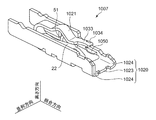
図23および図24に示すように、特許文献1に記載の電気コネクタは、メスコネクタの検知用メスコンタクト1007が、オスコネクタの検知用オスコンタクト1072に接触して電気的接続を検知するものである。
As shown in FIGS. 23 and 24, the electrical connector described in Patent Document 1 detects the electrical connection when the
検知用衝突バネ片1021の先端部1033には、検知用オスコンタクト1072に対して接触する接触部1034が形成されている。検知用オスコンタクト1072は、接触部1034が接触する接触面1075を有する。
検知用メスコンタクト1007には、接触部1034が対向する接触面1075との間に隙間GPができるように、検知用衝突バネ片1021を弾性変形させたときに、検知用衝突バネ片1021と物理的に干渉する干渉部1050が形成されている。
A
When the detection
検知用衝突バネ片1021と、検知用オスコンタクト1072とが接触するときには、図示しないロックアームに押圧されて、検知用衝突バネ片1021の先端部1033は干渉部1050の傾斜面1050aに接触するまで直線的に変位する。このとき、先端部1033は、干渉部1050の傾斜面1050aに沿って傾斜面1050a上を滑るように略円弧状に変位する。
When the collision spring piece for
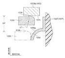
メスコネクタとオスコネクタとが正規に嵌合して、ロックアームの押圧が解除されると、検知用衝突バネ片1021の先端部1033は、干渉部1050の傾斜面1050aから離れて、検知用衝突バネ片1021のバネ復元力により元の位置に向かって直線的に戻ろうとする。このときの軌跡U1を二点鎖線で示す。先端部1033の接触部1034は、軌跡U1に沿って復元し始めると共に、間もなく検知用オスコンタクト1072の接続部1072bの接触面1075に対して斜めに衝突する。
When the female connector and the male connector are properly fitted and the lock arm is released, the
接触部1034が接触面1075に対して斜めに衝突することで、上記衝突後、接触部1034は、接触面1075に対して接触しながら接触面1075上を復元しようと検知用衝突バネ片1021と検知用通常バネ片(図示せず)が並べられた並列方向に移動する。そして、この復元により、接触部1034が接触面1075に対して摺動することで、ワイピングする。
When the
特許文献1に記載の電気コネクタでは、検知用衝突バネ片1021の先端部1033が、干渉部1050によって高さ方向に移動しながら並列方向に横移動することで、接触面1075に対して斜めに衝突させている。しかし、接触部1034が元の位置に向かって変位するときの隙間GPの距離が大きかったり、検知用衝突バネ片1021のばね性が強かったりすると、接触部1034が元の位置に戻る際の軌跡が不安定となるおそれがあり、ワイピング効果が期待できない。特に、接触部1034が、隙間GPを移動している間に、並列方向に移動して、元の位置に、直接戻ってしまうと、接触部1034が接触面1075に摺動しないため、接触部1034によるワイピング効果が得られない。
In the electrical connector described in Patent Document 1, the
従って、検知用衝突バネ片1021が検知用オスコンタクト1072に接触しているにも関わらず、非接触状態であると誤認するおそれがある。
Therefore, there is a possibility that the detection
そこで本発明は、相手方端子を確実に摺動することで、接触信頼性を向上させることができる端子および電気コネクタを提供することを目的とする。 Then, an object of this invention is to provide the terminal and electrical connector which can improve contact reliability by sliding a counterpart terminal reliably.
本発明は、電気コネクタの第一ハウジングの内部に配置される端子であって、前記第一ハウジングには、当該第一ハウジングが第二ハウジングと嵌合するときに、弾性的に撓んだ後に復帰して、前記第二ハウジングに係止するロックアームが形成されており、前記端子は、前記第一ハウジングが前記第二ハウジングと嵌合したときに、前記第二ハウジングに設けられた相手方端子と電気的に接触し、前記端子は、前記第一ハウジングに取り付けられるベース部と、前記ベース部と連続しており、前記ロックアーム部の撓みに連動して撓む弾性部と、前記弾性部と連続している接触部と、からなり、前記接触部は、前記第一ハウジングと第二ハウジングとが相互に嵌合する第一方向と交差する面内において形成され、前記弾性部が復帰するときに前記相手方端子の表面に接触する傾斜面を備えていることを特徴とする。 The present invention is a terminal disposed inside a first housing of an electrical connector, wherein the first housing is elastically bent when the first housing is fitted to the second housing. A lock arm that is returned and locked to the second housing is formed, and the terminal is a counterpart terminal provided on the second housing when the first housing is engaged with the second housing. The terminal is connected to the first housing; the elastic portion that is continuous with the base portion and bends in conjunction with the bending of the lock arm portion; and the elastic portion The contact portion is formed in a plane intersecting the first direction in which the first housing and the second housing are fitted to each other, and the elastic portion is restored. When Characterized in that it comprises an inclined surface in contact with the surface of the counterpart terminal.
また、本発明の電気コネクタは、前記第一ハウジングと、前記第一ハウジングと第二ハウジングとの嵌合時に、弾性的に撓んだ後に復帰して、前記第二ハウジングに係止するロックアームと、前記第一ハウジングが前記第二ハウジングと嵌合したときに、前記第二ハウジングに設けられた相手方端子と電気的に接続する本発明の端子と、からなるものである。 Further, the electrical connector of the present invention is a lock arm that returns after being elastically bent when the first housing and the first housing and the second housing are fitted, and is locked to the second housing. And the terminal of the present invention that is electrically connected to a counterpart terminal provided on the second housing when the first housing is fitted to the second housing.
本発明によれば、第一ハウジングが第二ハウジングと嵌合するときに、第二ハウジングに係止するロックアームが弾性的に撓んだ後に復帰する。このロックアームの撓みに連動して弾性部が撓む。この弾性部に連続した接触部に形成された傾斜面は、弾性部が復帰するときに相手方端子の表面に接触する。従って、ロックアームに連動させて弾性部が復帰するときに傾斜面を相手方端子に摺動させることができる。 According to the present invention, when the first housing is fitted to the second housing, the lock arm that is locked to the second housing is returned after being elastically bent. The elastic portion bends in conjunction with the bending of the lock arm. The inclined surface formed in the contact portion continuous with the elastic portion comes into contact with the surface of the counterpart terminal when the elastic portion returns. Accordingly, the inclined surface can be slid to the counterpart terminal when the elastic portion returns in conjunction with the lock arm.
前記傾斜面が前記相手方端子の表面に接触しながら、前記弾性部が復帰するときに、前記弾性部が前記相手方端子から離れる方向へ変形することが望ましい。
弾性部が相手方端子から離れる方向へ変形すると、傾斜面による相手方端子への押圧力を緩和させることができるので、傾斜面により相手方端子に大きな傷が付くことを軽減することができる。
It is desirable that when the elastic portion returns while the inclined surface is in contact with the surface of the counterpart terminal, the elastic portion is deformed in a direction away from the counterpart terminal.
When the elastic portion is deformed in the direction away from the counterpart terminal, the pressing force applied to the counterpart terminal by the inclined surface can be relieved, so that the counterpart terminal can be reduced from being greatly damaged by the inclined surface.
前記接触部には前記相手方端子が通過可能な開口部が形成されており、前記傾斜面は前記開口部の内縁に形成されていることが望ましい。
傾斜面が開口部の内縁に形成されていることで、開口部の傾斜面以外の残余の部分により傾斜面の両端部を補強することができるため、接触部の強度を向上させることができる。
It is preferable that an opening through which the counterpart terminal can pass is formed in the contact portion, and the inclined surface is formed at an inner edge of the opening.
Since the inclined surface is formed at the inner edge of the opening, both ends of the inclined surface can be reinforced by the remaining portions other than the inclined surface of the opening, and therefore the strength of the contact portion can be improved.
前記第一方向およびその逆方向の少なくとも一つの方向に延びる延長部が前記傾斜面に連続して前記接触部の一部を折り曲げることにより形成されていることが望ましい。
延長部が傾斜面に形成されていることで、延長部が幅広く相手方端子を摺動するため、相手方端子の表面の汚れや腐食を幅広く除去することができる。
It is desirable that an extension portion extending in at least one of the first direction and the opposite direction is formed by bending a part of the contact portion continuously with the inclined surface.
Since the extension portion is formed on the inclined surface, the extension portion slides on the counterpart terminal widely, so that the contamination and corrosion of the surface of the counterpart terminal can be widely removed.
前記弾性部は、先端側より基端側が細く形成されていることが望ましい。そうすることで、弾性部を撓ませやすくすることができる。 It is desirable that the elastic part is formed so that the base end side is thinner than the front end side. By doing so, an elastic part can be made easy to bend.
前記端子の少なくとも何れか一方の側において前記端子と並列して形成された少なくとも一つの第二端子をさらに備えており、前記第二端子は、前記ベース部と連続している第二弾性部と、前記第二弾性部と連続し、前記第二ハウジングに設けられた第二の相手方端子と接触する第二接触部と、からなるものであることが望ましい。 The terminal further includes at least one second terminal formed in parallel with the terminal on at least one side of the terminal, and the second terminal includes a second elastic portion that is continuous with the base portion; It is desirable that the second contact portion is continuous with the second elastic portion and is in contact with a second mating terminal provided in the second housing.
前記端子の少なくとも何れか一方の側に備えた、端子と並列して形成された少なくとも一つの第二端子が、第二の相手方端子と接触することで、相手方端子と接触する端子と、第二の相手方端子と接触する第二端子とがベース部を介して短絡した状態とすることができる。従って、第一ハウジングと第二ハウジングとの嵌合が正規な状態である否かの判定を、相手方端子と第二の相手方端子との間で検知することがきる。 At least one second terminal formed in parallel with the terminal provided on at least one side of the terminal is in contact with the second counterpart terminal, whereby the second contact terminal is contacted with the second counterpart terminal; The second terminal that contacts the other terminal can be short-circuited via the base portion. Accordingly, it is possible to detect whether the fitting between the first housing and the second housing is in a normal state between the counterpart terminal and the second counterpart terminal.
前記第二弾性部は、先端側が基端側より細く形成され、前記第二弾性部は、前記弾性部と同一面内において並列するように配置されていることが望ましい。
先端側が基端側より細く形成された第二弾性部を、先端側より基端側が細く形成された弾性部に、同一面内において並列するように配置することで、第二弾性部の細い先端側が弾性部の太い先端側に、第二弾性部の太い先端側が弾性部の細い先端側に並べられるため、それぞれを接近させて配置することができる。
It is desirable that the second elastic portion is formed so that the distal end side is narrower than the proximal end side, and the second elastic portion is arranged in parallel with the elastic portion in the same plane.
Narrow tip of the second elastic part by arranging the second elastic part whose tip side is narrower than the base end side in parallel with the elastic part whose base side is thinner than the tip side in the same plane Since the side is arranged on the leading end side of the elastic portion and the leading end side of the second elastic portion is arranged on the thin tip side of the elastic portion, they can be arranged close to each other.
前記端子は一枚の金属板からなるものであることが望ましい。各部が分離したものを接合して形成する場合と比較して、接合工程が不要であるため、容易に前記端子を作製することができる。 The terminals are preferably made of a single metal plate. Compared to the case where each part is separated and joined, a joining process is not required, so that the terminal can be easily manufactured.
本発明の電気コネクタは、前記第二ハウジングと、前記第二ハウジングが第一ハウジングと嵌合したときに、前記第一ハウジングに設けられた請求項1記載の端子と電気的に接続する相手方端子とを備え、前記相手方端子は、前記端子の傾斜面が接触しながら、前記端子の弾性部が復帰するときに、前記傾斜面から離れる方向へ変形することを特徴とする。 The electrical connector according to the present invention includes the second housing and a counterpart terminal that is electrically connected to the terminal of the first housing when the second housing is fitted to the first housing. The counterpart terminal is deformed in a direction away from the inclined surface when the elastic portion of the terminal is restored while the inclined surface of the terminal is in contact.
本発明の電気コネクタによれば、相手方端子が傾斜面から離れる方向へ変形しながら、接触部が復帰方向へ移動することにより、傾斜面による相手方端子への押圧力を調整することができる。従って、傾斜面により相手方端子に大きな傷が付くことを軽減することができる電気コネクタとすることができる。 According to the electrical connector of the present invention, the pressing force applied to the counterpart terminal by the inclined surface can be adjusted by moving the contact portion in the return direction while the counterpart terminal is deformed in a direction away from the inclined surface. Therefore, it can be set as the electrical connector which can reduce that an other party terminal gets a big damage | wound by an inclined surface.
本発明は、ロックアームに連動させて弾性部が復帰するときに傾斜面を相手方端子に摺動させることができるので、相手方端子と確実に摺動し、接触信頼性を向上させることができる。 According to the present invention, when the elastic portion returns in conjunction with the lock arm, the inclined surface can be slid to the mating terminal, so that it can slide reliably with the mating terminal and contact reliability can be improved.
本発明の実施の形態に係る電気コネクタを図面に基づいて説明する。なお、以下の説明においての「前後」という表現は、相手側の電気コネクタに挿入する側を「前」とし、その反対方向を「後」として表現したものである。また、本実施の形態では、上下の方向を、ロックアーム側を上、その反対側を下として説明している。 An electrical connector according to an embodiment of the present invention will be described with reference to the drawings. In the following description, the expression “front / rear” represents the side to be inserted into the mating electrical connector as “front” and the opposite direction as “rear”. Further, in the present embodiment, the vertical direction is described with the lock arm side being up and the opposite side being down.
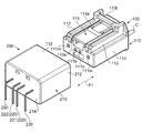
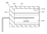
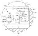
図1に示す雌側の電気コネクタである第1電気コネクタ100と、雄側の電気コネクタである第2電気コネクタ200とは、安全装置の一例である車両のエアバッグを始動させる電気配線に使用される電気コネクタである。第1電気コネクタ100と第2電気コネクタ200は、それぞれ2本の信号用の接触端子を有している。
まず、第1電気コネクタ100を、図面に基づいて説明する。
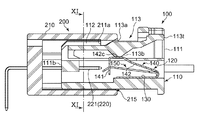
図2から図4に示すように、第1電気コネクタ100は、第2電気コネクタ200と嵌合する本発明の第一ハウジングであるインナーハウジング110と、インナーハウジング110の内部に配置され、第2電気コネクタ200の後述する検知用端子と接触して、第2電気コネクタ200との電気的接続を検知する本発明の端子である短絡用端子120と、雌側の信号用接続端子である雌側接触端子(図示せず)を備えている。
A first
First, the 1st
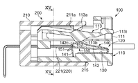
As shown in FIGS. 2 to 4, the first
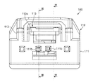
インナーハウジング110は、直方体状の本体111と、この本体111の天面に形成された一対の案内部112と、嵌合状態のときに第2電気コネクタ200からの抜けを防止するためのロックアーム113とを備えた樹脂成形品である。
The
本体111には、短絡用端子120を配置するための端子収容室111aが形成されている。本体111の前面には、第2電気コネクタ200の後述する検知用端子を差し込むための挿入孔111bが形成されている。また、本体111の前面には、第2電気コネクタ200の雄型端子を差し込むための挿入孔111m(図1参照)が形成されている。
In the
ロックアーム113は、前端部113sが本体111に繋がり、後端部113tは自由端とすることで、前端部113sを連結部として、後端部113t側が揺動するように形成されている。ロックアーム113の前端部113sは、板ばねを介在させて本体111と接続することが可能であり、板ばねが樹脂製の場合は、本体111とロックアーム113とを一体的に形成することで、ロックアーム113の後端部に付勢力を持たせることができる。
ロックアーム113には、第2電気コネクタ200のアウターハウジングとの嵌合時に、弾性的に撓んで沈み込んだ後に復帰して、アウターハウジングに突起部113aが形成されている。また、ロックアーム113には、中央部の短絡用端子120側に、短絡用端子120を押圧するための押圧部113bが形成されている。
The
When the second
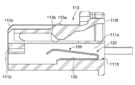
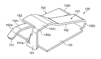
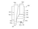
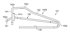
図5から図7に示すように、短絡用端子120は、1枚の金属板を打ち抜き、折り曲げ加工することで形成されている。
短絡用端子120は、インナーハウジング110に取り付けられるベース部130と、ベース部130に並ぶようにして配置された第1短絡用端子140および第2短絡用端子150とを備えている。
ベース部130は、図3および図4に示すように、インナーハウジング110の端子収容室111aに形成されたスロット部に固定される。短絡用端子120は、インナーハウジング110の後端部111dから挿入され、ベース部130をスロット部に差し込んで、端子収容室111aを前方に進めて配置される。
As shown in FIGS. 5 to 7, the short-
The short-
As shown in FIGS. 3 and 4, the
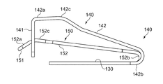
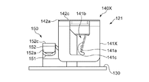
第1短絡用端子140(端子)は、検知用端子に接触する第1接触部141と、ロックアーム113の撓みに連動する第1弾性部142とを備えている。
第1接触部141(接触部)は、第1弾性部142の先端部142aから垂下するように設けられ、第1弾性部142に連続して形成されている。第1接触部141は、インナーハウジング110とアウターハウジング210とが相互に嵌合する第一方向F1(図1参照)と交差する面内において形成され、第1弾性部142が復帰するときに、相手方端子である検知用端子の表面に接触する傾斜面141aを備えている。
The first short-circuit terminal 140 (terminal) includes a
The first contact portion 141 (contact portion) is provided so as to hang from the
第1弾性部142(弾性部)は、基端部142bがベース部130からU字状に折り曲げられて前方へ向いた後、頂部142cまで徐々に上り傾斜となり、頂部142cから先端部142aに向かって下り傾斜となって第1接触部141に繋がっている。
第1弾性部142の頂部142cは、ロックアーム113の押圧部113bにより押圧される。
The first elastic portion 142 (elastic portion) has a
The
第2短絡用端子150(第二端子)は、検知用端子に接触する第2接触部151と、弾性的に撓む第2弾性部152とを備えている。
第2接触部151は、第2弾性部152の先端部152aに設けられ、検知用端子側が膨出するように折り曲げられて形成されている。
第2弾性部152(第二弾性部)は、基端部152bがベース部130からU字状に折り曲げられて前方へ向いた後、頂部152cまで緩やかに上り傾斜となり、頂部152cから先端部152aに向かって下り傾斜となって第2接触部151に繋がっている。
The second short-circuit terminal 150 (second terminal) includes a
The
The second elastic portion 152 (second elastic portion) has a
雌側接触端子は、図1に示す第1電気コネクタ200の雄側接触端子230を挟み込むようにして接触する金属薄板による板ばねを有している。雌側接触端子は、雌側接触端子の後端部で、本体111からまっすぐ突出したケーブルCと連結される。
The female contact terminal has a leaf spring made of a thin metal plate that comes into contact with the
次に、第2電気コネクタ200について、図1,図8および図9に基づいて説明する。
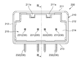
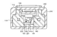
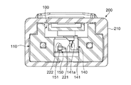
第2電気コネクタ200は、第1電気コネクタ100と嵌合するアウターハウジング210と、第1電気コネクタ100の短絡用端子120(図1参照)と接触して、第1電気コネクタ100との電気的接続を検知する検知用端子220と、雄側の信号用接続端子である雄側接触端子230とを備えている。
Next, the 2nd
The second
アウターハウジング210(第二ハウジング)は、矩形箱状に形成された樹脂成形品である。アウターハウジング210には、天面部211と、一対の側壁部212と、底壁部213と、奥壁部214とにより囲まれた嵌合穴215が形成されている。
The outer housing 210 (second housing) is a resin molded product formed in a rectangular box shape. The
天面部211の内側面には、一対の係止用爪部211aが形成されている。
係止用爪部211aは、ロックアーム113の突起部113a(図1参照)に引っ掛けるために、突起部113aの位置に対応させて嵌合穴215の開口部に形成されている。
奥壁部214には、検知用端子220が、嵌合穴215の開口部に向かって真っ直ぐに突出している。
A pair of locking
The locking
On the
検知用端子220は、挿抜方向に沿って延びる断面矩形状の針状端子である。検知用端子220は、基板と接続するために逆L字状に折り曲げられている。検知用端子220は、第1短絡用端子140と接続する第1検知用端子221(相手方端子)と、第2短絡用端子150と接続する第2検知用端子222(第二の相手方端子)とを備えている。
一対の検知用端子220(第1検知用端子221,第2検知用端子222)は、導通状態であれば、一対の検知用端子220が短絡用端子120により短絡させられていると判断でき、第1電気コネクタ100と第2電気コネクタ200との嵌合が正規な状態であると判定することができる。
The
If the pair of detection terminals 220 (the
図8および図9に示すように、雄側接触端子230は、検知用端子220両側に配置されている。雄側接触端子230は、嵌合穴215に針状の接触部231が、奥壁部214から突出して形成されていると共に、奥壁部214を貫通して逆L字状に延びる信号用基板端子部232が形成されている。
As shown in FIGS. 8 and 9, the
次に、本実施の形態に係る第1電気コネクタ100と第2電気コネクタ200との嵌合動作および使用状態を図面に基づいて説明する。
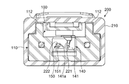
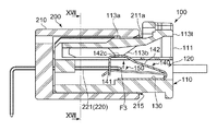
まず、第1電気コネクタ100の前部を第2電気コネクタ200の嵌合穴215に合わせて挿入して進行させる。図10および図11に示すように、インナーハウジング110を、アウターハウジング210の嵌合穴215に向かって、相互に嵌合する方向に進行させると、相対的に第2電気コネクタ200の検知用端子220がインナーハウジング110の挿入孔111bに差し込まれて、短絡用端子120へ向かって進行する。
Next, a fitting operation and a use state of the first
First, the front part of the first
インナーハウジング110の案内部112が嵌合穴215の内壁に沿って奥側へ進行することで、インナーハウジング110が嵌合穴215にまっすぐに挿入される。この状態では、ロックアーム113の突起部113aは、アウターハウジング210の係止用爪部211aと対向した状態である。
突起部113aと係止用爪部211aとが対向して、押し合っていない初期状態では、ロックアーム113の押圧部113bは、第1短絡用端子140の第1弾性部142を押圧していない状態である。
また、第1検知用端子221と第2検知用端子222とは、接触位置まで到達していないため、それぞれが第1短絡用端子140と第2短絡用端子150とに接触していない状態である。
The
In the initial state where the
Further, since the
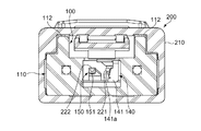
図12および図13に示すように、係止用爪部211aの前側斜面が、突起部113aの前側斜面に突き当たった状態から、更にインナーハウジング110を進行させると、第2検知用端子222は、第2短絡用端子150の第2接触部151に接触し始める。
As shown in FIG. 12 and FIG. 13, when the
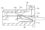
また、突起部113aが係止用爪部211aの前側斜面に摺動しながら押され、ロックアーム113が短絡用端子120側に押し下げられる。このときロックアーム113は、前端部113sが本体111に繋がり、後端部113tが自由端であるため、後端部113t側は前端部113sにより押し上げの付勢力を受けながら、前端部113sを支点として後端部113tが沈み込む。また、ロックアーム113の押圧部113bが短絡用端子120側に移動することで、押圧部113bが第1短絡用端子140の第1弾性部142の頂部142cを押圧する。
Further, the
この押圧部113bによる押圧により、第1弾性部142の頂部142cがベース部130側へ押し下げられることで、第1接触部141もベース部130側へ下がる。
第1接触部141がベース部130側へ移動することで、傾斜面141aも移動する。
傾斜面141aは、図18に示すように、一側となる先端部141sから他側となる基端部141t側に向かって、図12および図18に示すように押圧部113bによる押圧方向F2(第1接触部141の移動方向)と直交する方向における第1検知用端子221との距離が長くなるように傾斜している。
第1接触部141が第1検知用端子221と接触していない状態で、第1接触部141がベース部130側へ移動することで、第1接触部141の傾斜面141aは第1検知用端子221と非接触状態で、更に第1検知用端子221から離間する。従って、傾斜面141aは第1検知用端子221と非接触状態を維持する。
By the pressing by the
As the
As shown in FIG. 18, the
When the
続いて、図14および図15に示すように、突起部113aと係止用爪部211aとの前側斜面同士の摺動が過ぎ、突起部113aと係止用爪部211aとの天面同士が対峙した位置にあるときが、ロックアーム113が最も撓んだ状態(ロックアーム113の押圧部113bの最下点)となる。
第2短絡用端子150の第2接触部151は、インナーハウジング110とアウターハウジング210との嵌合が進むことで、第2検知用端子222の基端部側へ摺動しながら移動する。この第2接触部151と第2検知用端子222とが摺動することで、第2接触部151と第2検知用端子222とはワイピング効果を得ることができる。
Subsequently, as shown in FIGS. 14 and 15, the front slopes of the
The
ロックアーム113の押圧部113bが最下点に位置した状態では、第1短絡用端子140の第1接触部141は、更に下がった位置にある。従って、第1接触部141の傾斜面141aは、更に第1検知用端子221から離間した状態となるため、第1検知用端子221と非接触状態を維持したままである。
In a state where the
続いて、図16および図17に示すように、係止用爪部211aが突起部113aを越えると、ロックアーム113が弾性復帰することで、係止用爪部211aの後端面と突起部113aの後端面とが対面し係止する。この係止により、第1電気コネクタ100が第2電気コネクタ200から抜去されることを防止する。
更に、インナーハウジング110とアウターハウジング210との嵌合が進むことで、第2短絡用端子150の第2接触部151の接触位置は、更に第2検知用端子222の基端側へ摺動しながら移動する。
Subsequently, as shown in FIGS. 16 and 17, when the locking
Furthermore, as the fitting between the
ロックアーム113の弾性復帰によりロックアーム113が、前端部113sを支点として後端部113tが浮き上がり、嵌合前の元の位置に戻る。ロックアーム113が元の位置に戻ることで、ロックアーム113の押圧部113bが上昇して第1短絡用端子140から離間するため、第1短絡用端子140への押圧が解除される。
押圧部113bによる押圧が解除されることで、第1短絡用端子140の第1弾性部142は、弾性復帰する。
Due to the elastic return of the
The first
第1弾性部142の弾性復帰により、第1接触部141は、押圧方向とは反対方向(復帰方向F3)へ移動する。この移動により、傾斜面141aは徐々に第1検知用端子221に、接近し、そして接触して摺動し始める。
この第1接触部141の傾斜面141aが第1検知用端子221に摺動することで、第1接触部141と第1検知用端子221とはワイピング効果を得ることができる。
Due to the elastic return of the first
Since the
図18に示すように、更に、傾斜面141aの第1検知用端子221への摺動位置が復帰方向F3へ移動すると、傾斜面141aによる第1検知用端子221への押圧力が高くなる。そのため、変形しない第1検知用端子221に押され、第1接触部141は、第1検知用端子221から離れる方向(離間方向F4)へ第1弾性部142が変形することで移動する。
As shown in FIG. 18, when the sliding position of the
第1弾性部142は、先端側(先端部142a)より基端側(基端部142b)が細く形成されているため、離間方向F4へ変形しやすく形成されている。従って、第1検知用端子221より先に、第1弾性部142を変形させることができる。
第1接触部141が、強く第1検知用端子221を押圧しても、復帰方向F3へ移動しつつ、第1弾性部142が変形して離間方向F4へ移動することで、傾斜面141aによる第1検知用端子221への押圧力を緩和させることができる。従って、傾斜面141aにより第1検知用端子221に大きな傷が付くことを軽減することができる。
このようにして、第1短絡用端子140と第1検知用端子221とが接触し、および第2短絡用端子150と第2検知用端子222とが接触した状態で、第1電気コネクタ100と第2電気コネクタ200との嵌合が完了する。
従って、第1電気コネクタ100と第2電気コネクタ200とが正常に嵌合したか否かを、第1検知用端子221と第2検知用端子222との導通により、判定することができる。
The first
Even if the
In this way, in a state where the first short-
Therefore, whether or not the first
以上のように本実施の形態に係る第1電気コネクタ100と第2電気コネクタ200によれば、インナーハウジング110とアウターハウジング210との嵌合時に、ロックアーム113が撓むと、この撓みに連動して、第1短絡用端子140の第1弾性部142が第1接触部141を押圧方向F2に、第1検知用端子221と非接触状態のまま押し下げる。そして、ロックアーム113が復帰すると、この復帰に連動して、第1短絡用端子140の第1弾性部142が第1接触部141を復帰方向へ移動する。その際に、第1接触部141の傾斜面141aが第1検知用端子221を摺動するため、確実に摺動させることができる。
従って、第1短絡用端子140や第1検知用端子221に汚れや腐食があっても、相互の摺動による摩擦によって第1短絡用端子140や第1検知用端子221の汚れや腐食が除去されるので、第1短絡用端子140および第1検知用端子221の接触信頼性を著しく向上させることができる。
As described above, according to the first
Accordingly, even if the first short-
なお、本実施の形態では、第1弾性部142が変形することで、第1接触部141が、復帰方向F3へ移動しつつ、離間方向F4へ移動していたが、傾斜面141aが第1検知用端子221に摺動しながら復帰方向F3へ移動することで、第1弾性部142の代わりに第1検知用端子221が変形してもよい。
そうすることで、第1検知用端子221が傾斜面141aから離れる方向へ変形しながら、第1接触部141が復帰方向F3へ移動することにより、傾斜面141aによる第1検知用端子221への押圧力を緩和させることができる。従って、傾斜面141aにより第1検知用端子221に大きな傷が付くことを軽減することができる。
In the present embodiment, the first
By doing so, the
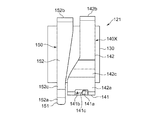
ここで、短絡用端子の変形例について、図面に基づいて説明する。なお、図19から図22においては、図5から図7と同じ構成のものは同符号を付して説明を省略する。
図19から図22に示すように、短絡用端子121は、第1短絡用端子140Xの第1接触部141Xが環状に形成されていることで、相手方端子である第1検知用端子221(図9参照)が通過可能な開口部141bが形成されている。そして、傾斜面141aを開口部141bの内縁に形成している。
第1接触部141Xを、開口部141bを有する環状とすることで、傾斜面141a以外の残余の部分が傾斜面141aの両端部を補強するため、傾斜面141aが第1検知用端子221に接触する第1接触部141Xの強度を向上させることができる
Here, a modification of the shorting terminal will be described with reference to the drawings. In FIGS. 19 to 22, the same components as those in FIGS. 5 to 7 are denoted by the same reference numerals and description thereof is omitted.
As shown in FIGS. 19 to 22, the short-
By forming the
また、第1接触部141Xは、第一方向F1(図1参照)となる第1検知用端子221の挿入方向に延びる延長部141cが、傾斜面141aに連続して形成されている。
この延長部141cは、第1接触部141Xの一部を折り曲げることにより形成することができる。
このように、傾斜面141aに連続して延長部141cを形成することで、第1検知用端子221との摺動面積を広くすることができるので、第1検知用端子221の表面の汚れや腐食を幅広く除去することができる。
In addition, the
The
Thus, by forming the
なお、延長部141cは、第1検知用端子221の挿入方向に延びるように形成されているが、その反対方向に延びるように形成してもよい。しかし、第1弾性部142の向きが変わり、延長部141cの先端部が第1検知用端子221の挿入に障害となるおそれがあるため、延長部141cは第1検知用端子221の挿入方向に延びるように形成されている方が望ましい。
The
図7に示す第1短絡用端子140および図22に示す第1短絡用端子140Xの第1弾性部142は、先端側(先端部142a)より基端側(基端部142b)が細く形成されている。また、第1短絡用端子140または第1短絡用端子140Xに並ぶ第2短絡用端子150の第2弾性部152は、先端側(先端部152a)が基端側(基端部152b)より細く形成されている。そして、第2短絡用端子150の第2弾性部152は、第1短絡用端子140または第1短絡用端子140Xの第1弾性部142と同一面内において並列するように配置されている。
従って、第1弾性部142の細い基端部142bを、第2弾性部152の太い基端部152bに配置させ、第1弾性部142の太い先端部142aを、第2弾性部152の細い先端部152aに配置させると、それぞれを接近させて配置することができる。従って、短絡用端子120,121を小型化することができる。
The first
Accordingly, the thin
また、短絡用端子120,121は、1枚の金属板を打ち抜き、折り曲げ加工することで形成されているため、各部が分離したものを接合して形成する場合と比較して、接合工程が不要であるため、容易に作製することができる。
In addition, since the short-
本発明は、電気信号を導通する電線の接続手段として、自動車産業、電気電子機器産業あるいは各種機械産業などの分野において広く利用される電気コネクタに好適である。特に、本発明は、安全装置に使用される電気コネクタに最適である。 INDUSTRIAL APPLICABILITY The present invention is suitable for electrical connectors widely used in fields such as the automobile industry, electrical / electronic equipment industry, and various machine industries as a means for connecting electric wires that conduct electrical signals. In particular, the present invention is optimal for electrical connectors used in safety devices.
100 第1電気コネクタ(電気コネクタ)
110 インナーハウジング(第一ハウジング)
111 本体
111a 端子収容室
111b 挿入孔
111d 後端部
111m 挿入孔
112 案内部
113 ロックアーム
113a 突起部
113b 押圧部
113s 前端部
113t 後端部
120,121 短絡用端子(端子)
130 ベース部
140,140X 第1短絡用端子
141,141X 第1接触部
141a 傾斜面
141b 開口部
141c 延長部
141s 先端部
141t 基端部
142 第1弾性部(弾性部)
142a 先端部
142b 基端部
142c 頂部
150 第2短絡用端子
151 第2接触部(第二接触部)
152 第2弾性部(第二弾性部)
152a 先端部
152b 基端部
152c 頂部
200 第2電気コネクタ
210 アウターハウジング
211 天面部
211a 係止用爪部
212 側壁部
213 底壁部
214 奥壁部
215 嵌合穴
220 検知用端子
221 第1検知用端子(相手方端子)
222 第2検知用端子(第二の相手方端子)
230 雄側接触端子
231 接触部
232 信号用基板端子部
F1 第一方向
F2 押圧方向
F3 復帰方向
F4 離間方向
100 First electrical connector (electrical connector)
110 Inner housing (first housing)
130 Base part 140,140X First short-circuiting terminal 141,141X
142a
152 2nd elastic part (2nd elastic part)
152a
222 Second detection terminal (second counterpart terminal)
230 Male
本発明は、電気コネクタの第一ハウジングの内部に配置される端子であって、前記第一ハウジングには、当該第一ハウジングが第二ハウジングと嵌合するときに、弾性的に撓んだ後に復帰して、前記第二ハウジングに係止するロックアームが形成されており、前記端子は、前記第一ハウジングが前記第二ハウジングと嵌合したときに、前記第二ハウジングに設けられた相手方端子と電気的に接触し、前記端子は、前記第一ハウジングに取り付けられるベース部と、前記ベース部と連続しており、前記ロックアーム部の押圧部に押圧されることで、前記ロックアーム部の撓みに連動して撓む弾性部と、前記弾性部と連続している接触部と、からなり、前記接触部は、前記第一ハウジングと第二ハウジングとが相互に嵌合する第一方向と交差する面内において形成され、前記弾性部が元の位置に復帰するときに前記相手方端子の表面に接触する一つの傾斜面を備えており、前記傾斜面は、前記押圧部の押圧方向における先端部から基端部側に向かって、前記押圧方向と直交する方向における前記相手方端子との距離が長くなるように傾斜していることを特徴とする。 The present invention is a terminal disposed inside a first housing of an electrical connector, wherein the first housing is elastically bent when the first housing is fitted to the second housing. A lock arm that is returned and locked to the second housing is formed, and the terminal is a counterpart terminal provided on the second housing when the first housing is engaged with the second housing. And the terminal is continuous with the base portion attached to the first housing and the base portion, and is pressed by the pressing portion of the lock arm portion , thereby An elastic portion that bends in conjunction with the bending, and a contact portion that is continuous with the elastic portion, and the contact portion has a first direction in which the first housing and the second housing are fitted to each other. Intersect Is formed at the inner, the elastic portion is provided with one of the inclined surfaces in contact with the surface of the counterpart terminal when returning to the original position, the inclined surface, based on the front end portion in the pressing direction of the pressing portion Inclined so as to increase the distance from the counterpart terminal in the direction orthogonal to the pressing direction toward the end side .
前記弾性部は、当該弾性部が元の位置に復帰するときに、前記傾斜面が前記相手方端子の表面に接触して、前記傾斜面による前記相手方端子への押圧力が高まることで、前記相手方端子に押され、前記相手方端子から離れる方向へ変形することが望ましい。
弾性部が相手方端子から離れる方向へ変形すると、傾斜面による相手方端子への押圧力を緩和させることができるので、傾斜面により相手方端子に大きな傷が付くことを軽減することができる。
When the elastic portion returns to the original position, the inclined surface comes into contact with the surface of the counterpart terminal, and the pressing force to the counterpart terminal by the inclined surface increases, so that the counterpart It is desirable to be deformed in a direction away from the counterpart terminal by being pushed by the terminal.
When the elastic portion is deformed in the direction away from the counterpart terminal, the pressing force applied to the counterpart terminal by the inclined surface can be relieved, so that the counterpart terminal can be reduced from being greatly damaged by the inclined surface.
本発明の電気コネクタは、前記第二ハウジングと、前記第二ハウジングが第一ハウジングと嵌合したときに、前記第一ハウジングに設けられた請求項1記載の端子と電気的に接続する相手方端子とを備え、前記相手方端子は、前記弾性部が復帰するときに、前記端子の傾斜面が接触して、前記傾斜面による前記相手方端子への押圧力が高まることで、前記傾斜面から離れる方向へ変形することを特徴とする。 The electrical connector according to the present invention includes the second housing and a counterpart terminal that is electrically connected to the terminal of the first housing when the second housing is fitted to the first housing. The counter terminal is in a direction away from the inclined surface when the inclined surface of the terminal comes into contact with the elastic portion and the pressing force to the counter terminal by the inclined surface increases. It is characterized by being transformed into
前記第一方向およびその逆方向の少なくとも一つの方向に延びる延長部が前記傾斜面に連続して前記接触部の一部に設けられていることが望ましい。
延長部が傾斜面に設けられていることで、延長部が幅広く相手方端子を摺動するため、相手方端子の表面の汚れや腐食を幅広く除去することができる。
It is desirable extensions are found provided on a part of the contact portion continuously to the inclined surface extending in at least one direction of the first direction and the opposite direction.
By extension is found provided on the inclined surface, for sliding the broad mating terminal extension, it can be widely remove dirt and corrosion of the surface of the counterpart terminal.
Claims (10)
前記第一ハウジングには、当該第一ハウジングが第二ハウジングと嵌合するときに、弾性的に撓んだ後に復帰して、前記第二ハウジングに係止するロックアームが形成されており、
前記端子は、前記第一ハウジングが前記第二ハウジングと嵌合したときに、前記第二ハウジングに設けられた相手方端子と電気的に接触し、
前記端子は、
前記第一ハウジングに取り付けられるベース部と、
前記ベース部と連続しており、前記ロックアーム部の撓みに連動して撓む弾性部と、
前記弾性部と連続している接触部と、
からなり、
前記接触部は、前記第一ハウジングと第二ハウジングとが相互に嵌合する第一方向と交差する面内において形成され、前記弾性部が復帰するときに前記相手方端子の表面に接触する傾斜面を備えていることを特徴とする端子。 A terminal disposed inside the first housing of the electrical connector,
The first housing is formed with a lock arm that returns after being elastically bent when the first housing is fitted to the second housing, and engages the second housing.
The terminal is in electrical contact with a counterpart terminal provided in the second housing when the first housing is engaged with the second housing,
The terminal is
A base portion attached to the first housing;
An elastic part that is continuous with the base part and bends in conjunction with the bending of the lock arm part;
A contact portion continuous with the elastic portion;
Consists of
The contact portion is formed in a plane intersecting a first direction in which the first housing and the second housing are fitted to each other, and is an inclined surface that contacts the surface of the counterpart terminal when the elastic portion returns. A terminal characterized by comprising.
前記第二端子は、
前記ベース部と連続している第二弾性部と、
前記第二弾性部と連続し、前記第二ハウジングに設けられた第二の相手方端子と接触する第二接触部と、
からなるものであることを特徴とする請求項5記載の端子。 Further comprising at least one second terminal formed in parallel with the terminal on at least one side of the terminal;
The second terminal is
A second elastic portion continuous with the base portion;
A second contact portion that is continuous with the second elastic portion and contacts a second mating terminal provided in the second housing;
The terminal according to claim 5, comprising:
前記第二弾性部は、前記弾性部と同一面内において並列するように配置されていることを特徴とする請求項6記載の端子。 The second elastic portion is formed such that the distal end side is narrower than the proximal end side,
The terminal according to claim 6, wherein the second elastic portion is arranged in parallel with the elastic portion in the same plane.
前記第一ハウジングと第二ハウジングとの嵌合時に、弾性的に撓んだ後に復帰して、前記第二ハウジングに係止するロックアームと、
前記第一ハウジングが前記第二ハウジングと嵌合したときに、前記第二ハウジングに設けられた相手方端子と電気的に接続する請求項1乃至8の何れか一項に記載の端子と、
からなる電気コネクタ。 The first housing;
When the first housing and the second housing are fitted, a lock arm that returns after being elastically bent and engages with the second housing;
The terminal according to any one of claims 1 to 8, wherein when the first housing is fitted to the second housing, the terminal is electrically connected to a counterpart terminal provided on the second housing;
An electrical connector consisting of
前記第二ハウジングが第一ハウジングと嵌合したときに、前記第一ハウジングに設けられた請求項1記載の端子と電気的に接続する相手方端子とを備え、
前記相手方端子は、前記端子の傾斜面が接触しながら、前記端子の弾性部が復帰するときに、前記傾斜面から離れる方向へ変形することを特徴とする電気コネクタ。 The second housing;
When the second housing is fitted to the first housing, the terminal according to claim 1 provided on the first housing, and a counterpart terminal electrically connected to the terminal.
The mating terminal is deformed in a direction away from the inclined surface when the elastic portion of the terminal is restored while the inclined surface of the terminal is in contact.
Priority Applications (1)
| Application Number | Priority Date | Filing Date | Title |
|---|---|---|---|
| JP2015025705A JP5920502B1 (en) | 2015-02-12 | 2015-02-12 | Terminals and electrical connectors |
Applications Claiming Priority (1)
| Application Number | Priority Date | Filing Date | Title |
|---|---|---|---|
| JP2015025705A JP5920502B1 (en) | 2015-02-12 | 2015-02-12 | Terminals and electrical connectors |
Publications (2)
| Publication Number | Publication Date |
|---|---|
| JP5920502B1 JP5920502B1 (en) | 2016-05-18 |
| JP2016149259A true JP2016149259A (en) | 2016-08-18 |
Family
ID=55974048
Family Applications (1)
| Application Number | Title | Priority Date | Filing Date |
|---|---|---|---|
| JP2015025705A Expired - Fee Related JP5920502B1 (en) | 2015-02-12 | 2015-02-12 | Terminals and electrical connectors |
Country Status (1)
| Country | Link |
|---|---|
| JP (1) | JP5920502B1 (en) |
Families Citing this family (1)
| Publication number | Priority date | Publication date | Assignee | Title |
|---|---|---|---|---|
| CN117347680B (en) * | 2023-12-06 | 2024-02-13 | 淮安市文善电子有限公司 | Electronic component detection device and operation method thereof |
Family Cites Families (1)
| Publication number | Priority date | Publication date | Assignee | Title |
|---|---|---|---|---|
| JP3264305B2 (en) * | 1995-01-09 | 2002-03-11 | 矢崎総業株式会社 | Connector with coupling detection device |
-
2015
- 2015-02-12 JP JP2015025705A patent/JP5920502B1/en not_active Expired - Fee Related
Also Published As
| Publication number | Publication date |
|---|---|
| JP5920502B1 (en) | 2016-05-18 |
Similar Documents
| Publication | Publication Date | Title |
|---|---|---|
| US7591665B2 (en) | Connector | |
| US7458835B2 (en) | Connector and a connector assembly | |
| JP4548272B2 (en) | connector | |
| US9876295B2 (en) | Electric connector | |
| US9300089B2 (en) | Electric connector and detection terminal included therein | |
| CN101335396B (en) | Connector and assembling method | |
| CN102332649B (en) | Connector provided with combination detection unit | |
| CN107919564B (en) | Connector | |
| JP7567561B2 (en) | connector | |
| US6422894B1 (en) | Connector fitting detection construction | |
| JP5247902B1 (en) | Electrical connector | |
| US11417990B2 (en) | Connector that includes assembly detecting portion | |
| JP5920502B1 (en) | Terminals and electrical connectors | |
| CN107809027B (en) | Connectors with short-circuit terminals | |
| JP5949970B1 (en) | Electrical connector | |
| CN113228425A (en) | Connector with a locking member | |
| JP5811154B2 (en) | Method for manufacturing electrical connector and short-circuit terminal | |
| WO2017026245A1 (en) | Electric connection device with fitting detection function | |
| JP6203665B2 (en) | A pair of electrical connectors with shutters on one side | |
| JP6270156B2 (en) | connector | |
| JP2009146673A (en) | Connector device with fitting detection function, connector part, and metallic lock arm for connector | |
| JP4010531B2 (en) | Half mating detection connector | |
| JP2009117193A (en) | Connector and detection terminal | |
| KR20250062177A (en) | connector assembly | |
| WO2024171678A1 (en) | Connector |
Legal Events
| Date | Code | Title | Description |
|---|---|---|---|
| A521 | Request for written amendment filed |
Free format text: JAPANESE INTERMEDIATE CODE: A523 Effective date: 20160223 |
|
| A521 | Request for written amendment filed |
Free format text: JAPANESE INTERMEDIATE CODE: A523 Effective date: 20160301 |
|
| TRDD | Decision of grant or rejection written | ||
| A01 | Written decision to grant a patent or to grant a registration (utility model) |
Free format text: JAPANESE INTERMEDIATE CODE: A01 Effective date: 20160315 |
|
| A61 | First payment of annual fees (during grant procedure) |
Free format text: JAPANESE INTERMEDIATE CODE: A61 Effective date: 20160328 |
|
| R150 | Certificate of patent or registration of utility model |
Ref document number: 5920502 Country of ref document: JP Free format text: JAPANESE INTERMEDIATE CODE: R150 |
|
| R250 | Receipt of annual fees |
Free format text: JAPANESE INTERMEDIATE CODE: R250 |
|
| R250 | Receipt of annual fees |
Free format text: JAPANESE INTERMEDIATE CODE: R250 |
|
| R250 | Receipt of annual fees |
Free format text: JAPANESE INTERMEDIATE CODE: R250 |
|
| R250 | Receipt of annual fees |
Free format text: JAPANESE INTERMEDIATE CODE: R250 |
|
| LAPS | Cancellation because of no payment of annual fees |