JP2016148564A - Current detector - Google Patents
Current detector Download PDFInfo
- Publication number
- JP2016148564A JP2016148564A JP2015024853A JP2015024853A JP2016148564A JP 2016148564 A JP2016148564 A JP 2016148564A JP 2015024853 A JP2015024853 A JP 2015024853A JP 2015024853 A JP2015024853 A JP 2015024853A JP 2016148564 A JP2016148564 A JP 2016148564A
- Authority
- JP
- Japan
- Prior art keywords
- current
- magnitude
- electric wire
- detected
- current detection
- Prior art date
- Legal status (The legal status is an assumption and is not a legal conclusion. Google has not performed a legal analysis and makes no representation as to the accuracy of the status listed.)
- Granted
Links
Images
Landscapes
- Measurement Of Current Or Voltage (AREA)
Abstract
Description
本発明は、電流の検出の有無及び検出された電流の方向を容易に確認可能な電流検出器に関する。 The present invention relates to a current detector capable of easily confirming whether or not a current is detected and the direction of the detected current.
配電線に地絡事故等が発生したときの事故点の探査方法として、健全区間から切り離された事故点を含む区間に高電圧パルスや直流電圧を印加し、CT受信器や漏れ電流計等で電流を検出し事故点を探査する方法が知られており、事故点探査の作業性を向上すべく、種々の提案がなされている。 As a method of searching for an accident point when a ground fault or the like occurs in a distribution line, a high voltage pulse or DC voltage is applied to the section including the accident point separated from the sound section, and a CT receiver or leak ammeter A method for detecting an accident point by detecting an electric current is known, and various proposals have been made to improve workability of the accident point search.
例えば、電流検出器の電流検出部を配電線に近接させる作業を容易にすべく、配電線の本数よりも多い数の電流検出部を配電線の間隔よりも短い間隔で並べて配置し、いずれかの電流検出部で配電線の電流を検出するように構成するとともに、電流を検出した電流検出部の特定を容易にすべく、電流が検出されると点灯するランプが各電流検出部に設けられた電流検出器が提案されている(例えば、特許文献1参照)。 For example, in order to facilitate the work of bringing the current detectors of the current detector close to the distribution lines, arrange more current detection units than the number of distribution lines side by side with a shorter interval than the distribution lines, In order to facilitate the identification of the current detection unit that has detected the current, each current detection unit is provided with a lamp that lights up when the current is detected. A current detector has been proposed (see, for example, Patent Document 1).
また電流の大きさ及び方向を検出し、電流の大きさが設定された閾値を超えるとブザーを鳴動させるとともに、電流の方向に応じて異なる色のランプを点灯させる電流検出器も提案されている(例えば、特許文献2参照)。 A current detector is also proposed that detects the current magnitude and direction, sounds a buzzer when the current magnitude exceeds a set threshold, and lights a lamp of a different color according to the current direction. (For example, refer to Patent Document 2).
特許文献1、2に記載の電流検出器によれば、事故点探査の作業性が向上するとともに、ランプが底面に設けられているので電流が検出されたことを下方から容易に視認することができる。しかしながら、特許文献2に記載の電流検出器において、ランプの色の違いにより電流の方向を判断するという方法は直感的ではない。
According to the current detectors described in
また近年では、碍子等の品質の向上により、事故点において流れる地絡電流の大きさが小さいことが多い。また分流等によっても地絡電流が小さくなることがある。地絡電流が小さい場合には、印加する電圧を大きくすることで地絡電流を増幅させるが、印加する電圧を大きくするためには、高圧ケーブルを切り離す必要があり、作業に時間が掛かっている。また状況によっては印加する電圧を大きくすることができない場合もあり、特許文献1、2に記載の電流検出器では閾値未満の電流を検出することができないので、地絡電流を検出することができない場合がある。
In recent years, the magnitude of the ground fault current flowing at the point of the accident is often small due to the improvement of the quality of insulators and the like. In addition, the ground fault current may be reduced due to a shunt. When the ground fault current is small, the ground fault current is amplified by increasing the voltage to be applied. However, in order to increase the voltage to be applied, it is necessary to disconnect the high voltage cable, which takes time. . Also, depending on the situation, the applied voltage may not be increased, and the current detectors described in
本発明の目的は、電流の検出の有無及び検出された電流の方向を容易に確認可能な電流検出器を提供することである。 An object of the present invention is to provide a current detector capable of easily confirming whether or not a current is detected and the direction of the detected current.
本発明は、電線を流れる電流の大きさ及び方向を検出可能な電流検出器であって、前記電線を囲うように前記電線に取付けられ前記電線を流れる電流の大きさ及び方向を検出する電流検出ユニットと、検出された電流の大きさを指示するアナログメーターと、検出された電流の方向に応じて点灯する2つの電流方向ランプとを備え、前記アナログメーターは、底面に配設され、2つの前記電流方向ランプは、前記電線を流れる電流の方向を容易に視認可能に、前記電流検出ユニットが前記電線に取付けられた状態で前記電線の長軸方向に並ぶように配設されていることを特徴とする電流検出器である。 The present invention is a current detector capable of detecting the magnitude and direction of a current flowing through an electric wire, wherein the current detector is attached to the electric wire so as to surround the electric wire and detects the magnitude and direction of the electric current flowing through the electric wire. A unit, an analog meter that indicates the magnitude of the detected current, and two current direction lamps that light according to the direction of the detected current, the analog meter being disposed on the bottom surface, The current direction lamp is arranged so that the direction of the current flowing through the electric wire can be easily visually recognized, and the current detection unit is arranged in the major axis direction of the electric wire in a state of being attached to the electric wire. This is a featured current detector.
また本発明の電流検出器は、さらに、前記アナログメーターの照度を向上させる照明手段を備えることを特徴とする。 In addition, the current detector of the present invention further includes illumination means for improving the illuminance of the analog meter.
また本発明の電流検出器は、さらに、検出された電流の大きさが予め設定された大きさを超えると点灯する、底面に配設された電流検出ランプ、及び/又は検出された電流の大きさが予め設定された大きさを超えると鳴動する電流検出ブザーを備えることを特徴とする。 Furthermore, the current detector of the present invention further includes a current detection lamp disposed on the bottom surface and / or a magnitude of the detected current that is lit when the magnitude of the detected current exceeds a preset magnitude. A current detection buzzer that rings when the value exceeds a preset size is provided.
また本発明の電流検出器において、前記アナログメーターは、複数の目盛が付された目盛盤と、複数の前記目盛のうち、前記電流検出ユニットで検出された電流の大きさに対応する前記目盛を指示する指示針とを備え、前記目盛毎に対応する電流の大きさを任意に設定可能であることを特徴とする。 In the current detector of the present invention, the analog meter has a scale plate with a plurality of scales, and the scale corresponding to the magnitude of the current detected by the current detection unit among the plurality of scales. An indicator needle for indicating is provided, and the magnitude of the current corresponding to each scale can be arbitrarily set.
また本発明の電流検出器は、さらに、間接活線作業に用いられる長尺な絶縁操作棒の先端に着脱自在に連結するジョイントを備え、前記電流検出ユニットは、回動自在な回動片を有し、前記絶縁操作棒の先端に連結した状態で前記絶縁操作棒の操作により前記回動片を前記電線に押し当てることで前記回動片を回動させ、前記電流検出ユニットを前記電線に着脱可能なことを特徴とする。 The current detector of the present invention further includes a joint that is detachably connected to the end of a long insulating operation rod used for indirect hot-wire work, and the current detection unit includes a rotatable rotating piece. The rotating operation piece is pressed against the electric wire by operating the insulating operation rod in a state of being connected to the tip of the insulating operation rod, and the current detecting unit is attached to the electric wire. It is characterized by being detachable.
本発明の電流検出器によれば、アナログメーターの動きから電流の検出の有無を確認することができるので、設定された閾値未満の電流や瞬間的に流れる電流に対してもアナログメーターの動きを確認することで電流の検出の有無を確認することができる。またアナログメーターが底面に配設されているので、高所又は地中に設置されている電線に取付けたときにアナログメーターを作業者側から確認し易い。さらに、2つの電流方向ランプを備え、電流方向ランプは、検出された電流の方向に応じて点灯するので、検出された電流の方向を直感的に判断することができる。このように本発明の電流検出器によれば、電流の検出の有無及び検出された電流の方向を容易に確認することができる。 According to the current detector of the present invention, the presence or absence of current detection can be confirmed from the movement of the analog meter. Therefore, the movement of the analog meter can be detected even when the current is less than the set threshold or when the current flows instantaneously. By checking, it can be confirmed whether or not current is detected. Moreover, since the analog meter is disposed on the bottom surface, it is easy to check the analog meter from the operator side when it is attached to an electric wire installed at a high place or in the ground. Furthermore, since two current direction lamps are provided and the current direction lamps are turned on according to the detected current direction, the detected current direction can be intuitively determined. Thus, according to the current detector of the present invention, the presence / absence of current detection and the direction of the detected current can be easily confirmed.
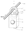
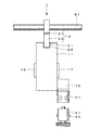
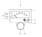
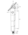
図1は、本発明の第1実施形態の電流検出器1の斜視図である。図2は、図1の電流検出器1の側面図である。図3は、図1の電流検出器1の底面図である。図4(a)は、図1の電流検出器1を電線81に取付ける際の動作を示す斜視図である。図4(b)は、図1の電流検出器1を電線81から取外す際の動作を示す斜視図である。本発明の電流検出器1は、電線81を流れる電流の大きさ及び方向を検出する電流検出器であって、配電線において地絡事故等が発生したときの事故点の探査に用いられる。
FIG. 1 is a perspective view of a
電流検出器1は、直方体の筐体11と、筐体11の上部に配設された電流検出ユニット12と、筐体11の底面に配設された、アナログメーター13、電流検出ランプ14及び電流検出ブザー15と、筐体11の正面及び背面に1つずつ配設された電流方向ランプ16、17と、筐体11の背面の下部に配設され間接活線作業で用いられる長尺な絶縁操作棒91を連結するジョイント18と、筐体11内に収容された図示しない制御手段、電源、その他必要に応じて操作ボタンや液晶表示部等を備え、電流検出ユニット12を介して電線81に取付けられ、電線81に流れる電流の大きさ及び方向を検出する。
The
筐体11は、合成樹脂製の箱体であり、電流検出ユニット12、アナログメーター13、電流検出ランプ14、電流検出ブザー15、制御手段、電源等を収容し携帯可能な大きさで形成されている。なお筐体11の材質は、特定の材質に限定されるものではなく、強度を確保しつつ軽量な材質であることが好ましい。
The
また筐体11の上部には、後述する電流検出ユニット12の回動片32が電流検出ユニット12の内側に回動したときに嵌り込む溝21が形成されている。
In addition, a
電流検出ユニット12は、ホール効果を利用して電線81に流れる電流の周囲に発生する磁界を検出するホール素子方式の電流検出手段であり、筐体11の上部に固定された、正面視においてC字状の固定片31と筐体11の上部に回動自在に取付けられた直方体ブロック状の回動片32とでリング状に構成され、電線81を囲うように電線81に取付けられ、電線81に流れる電流の大きさ及び方向を検出する。なお電流検出ユニット12は、ホール効果を利用した電流検出手段に限定されるものではなく、電流の大きさ及び方向を検出可能な他の方式の電流検出手段を用いることもできる
The
固定片31及び回動片32は、ホール効果により電流の周囲に発生する磁界を検出するホール素子を含む鉄心等の磁界検出手段(図示省略)を合成樹脂で覆うように形成されている。
The
回動片32は、電流検出ユニット12のリングの内側及び外側に回動自在に、図示しないバネの付勢力等により筐体11の上面に対して直角に立設し固定片31とリング状に繋がるように、回動軸となるシャフト22を介して筐体11に取付けられている。
The
アナログメーター13は、0から5までの目盛40が付された5段階表示の目盛盤41の目盛40を指示針42で指示するアナログメーターであり、電流検出ユニット12で検出された電流の大きさに応じた目盛40を指示針42が連続的に動いて指示する。
The
アナログメーター13において、目盛盤41の各目盛40に対応する電流の大きさは、任意の大きさに設定することができる。例えば、電流検出ユニット12で検出された電流の大きさが0.67Aのときには「5」の目盛40を指示し、電流の大きさが0.34Aのときには「3」の目盛40を指示するように設定することができ、各目盛40間の電流値の差が必ずしも均等になっていなくてもよい。
In the
アナログメーター13の目盛盤41は、5段階表示に限定されるものではなく、例えば、10段階表示としてもよい。またアナログメーター13の目盛盤41は、暗所でも視認可能に照度を向上させる照明手段であるバックライト43を備える。
The scale plate 41 of the
アナログメーター13の指示針42は、電流検出ユニット12が検出している電流の大きさに追随して動くように構成されている。またアナログメーター13には、指示針42に掛止し、指示針42が指示した最大値を保持する置き針(図示省略)が設けられていてもよい。
The indicator needle 42 of the
電流検出ランプ14は、電流検出ユニット12で検出された電流の大きさが予め設定された閾値を超えると点灯する。閾値は、任意に設定することが可能であり、例えば、アナログメーター13の「5」の目盛40に対応する電流の大きさと同じ大きさに設定しておくと、アナログメーター13の指示針42が「5」の目盛40を指示したときに電流検出ランプ14が点灯する。なお電流検出ランプ14の発光色は、特定の色に限定されるものではない。
The
また電流検出ランプ14を消灯するタイミングは、例えば、一定時間の経過後、又は操作ボタンによる消灯入力等、適宜最適なタイミングに設定すればよい。後述する電流検出ブザー15、電流方向ランプ16、17についても同様である。
Further, the timing for turning off the
電流検出ブザー15は、電流検出ユニット12で検出された電流の大きさが予め設定された閾値を超えると鳴動する。閾値は、基本的には、電流検出ランプ14の閾値と同じ値に設定されるが、これに限定されるものではない。
The
電流方向ランプ16、17は、電流検出ユニット12が電線81に取付けられた状態で電線81の長軸方向に並ぶように、筐体11の正面及び背面に1つずつ配設され、検出された電流の流れ方向の上流側に位置する電流方向ランプ16、17が点灯する。図1に示すように、電流検出ユニット12で検出された電流が筐体11の正面に向かって流れているときには、筐体11の正面に配設された電流方向ランプ16が点灯する。これに対し、電流検出ユニット12で検出された電流が筐体11の背面に向かって流れているときには、筐体11の背面に配設された電流方向ランプ17が点灯する。なお電流方向ランプ16、17が点灯する電流の大きさについても、電流検出ランプ14と同様、任意の大きさに設定することができる。
The
電流方向ランプ16、17の発光色は、特定の色に限定されるものではないが、検出された電流の方向の判断をより容易にすべく、互いに異なる色であることが好ましい。
The emission colors of the
ジョイント18は、間接活線作業に用いられる長尺な絶縁操作棒91の先端に設けられたピン92を係止させる係止溝51を備え、絶縁操作棒91と着脱自在に連結する、いわゆるツイストロック機構の連結手段である。
The joint 18 includes a locking
制御手段は、電流検出ユニット12や操作ボタンからの入力、及び設定された閾値や各目盛40に対応する電流値に基づき、アナログメーター13の指示針42、バックライト43、電流検出ランプ14、電流検出ブザー15、及び電流方向ランプ16、17を動作させる。なお制御手段や電源、操作ボタン等は、公知のものを使用すればよいため、詳細な説明は省略する。
Based on the input from the
次に本実施形態の電流検出器1を用いた事故点探査方法について説明する。電流検出器1を絶縁操作棒91の先端に連結させ、絶縁操作棒91を操作し電流検出器1(電流検出ユニット12)を電線81に取付ける。電流検出器1を電線81に取付ける際には、電流検出ユニット12の回動片32を電線81に押し当て回動片32を内側に回動させることで電流検出器1を電線81に容易に取付けることができる。
Next, an accident point search method using the
電流検出器1を電線81に取付けた状態で課電装置(図示省略)により電線81に高電圧パルス又は直流電圧を印加する。電流検出器1を取付けた電線81に事故点が含まれる場合には、電流検出器1が地絡電流を検出し、指示針42が地絡電流の大きさに応じた目盛40を指示するとともに、地絡電流の方向に応じて正面の電流方向ランプ16又は背面の電流方向ランプ17が点灯する。
With the
さらに検出された地絡電流の大きさが設定された閾値以上である場合には、電流検出ランプ14が点灯し、電流検出ブザー15が鳴動する。作業者は、アナログメーター13、電流検出ランプ14、電流検出ブザー15、電流方向ランプ16、17の動作を確認することで地絡電流の有無及び方向を判断し、事故点を絞り込む。
Further, if the detected magnitude of the ground fault current is equal to or greater than the set threshold value, the
電流検出器1を電線81から取外す際には、絶縁操作棒91を操作し電流検出ユニット12の回動片32を電線81に押し当て回動片32を外側に回動させることで電流検出器1を電線81から容易に取外すことができる。
When the
以上のように、本実施形態の電流検出器1は、正面及び背面に配設された電流方向ランプ16、17を備え、検出された電流の流れ方向の上流側に位置する電流方向ランプ16、17が点灯するので、検出された電流の方向を直感的に判断することができる。
As described above, the
また電流検出器1は、検出された電流の大きさが設定された閾値以上である場合に電流検出ランプ14が点灯し、電流検出ブザー15が鳴動するので、電流が検出されたことを容易に確認することができる。
In addition, the
さらに電流検出器1は、アナログメーター13を備えるので、分流等により電線81に流れる地絡電流が小さくなり、電流検出ユニット12で検出された電流の大きさが設定された閾値未満である場合でも、指示針42の動作を確認することで、電流が検出されたか否かを確認することができる。これにより課電装置の出力電圧を上げることなく地絡電流を検出することができるので、出力電圧を上げるための高圧線の切り離し作業等が不要となり、事故点探査作業を迅速に行うことができる。
Furthermore, since the
またデジタル式のメーターでは、瞬間的に流れる電流に対して数値が表示されたか否かを判断することが難しく、電流の検出の有無を確認することが困難であるが、アナログメーター13を用いることで、瞬間的に流れる電流に対しても指示針42の動作を確認することで、電流の検出の有無を確認することができる。 In addition, in a digital meter, it is difficult to determine whether or not a numerical value is displayed for a current that flows instantaneously, and it is difficult to check whether or not a current is detected. Thus, the presence or absence of current detection can be confirmed by confirming the operation of the indicator needle 42 even with respect to the instantaneously flowing current.
また電流検出器1では、アナログメーター13及び電流検出ランプ14が筐体11の底面に設けられているので、下方から容易に視認可能である。さらにアナログメーター13がバックライト43を備えるので、暗所でも視認可能である。なおアナログメーター13の視認性をさらに向上すべく、例えば、拡大鏡(図示省略)等を設けてもよい。
In the
また電流検出器1は、電流検出ユニット12に回動片32を備えるので、絶縁操作棒91を用いた間接活線作業においても電線81への着脱を容易に行うことができる。
In addition, since the
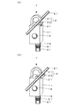
図5は、本発明の第2実施形態の電流検出器2の斜視図である。図1から図4に示す第1実施形態の電流検出器1と同一の構成には同一の符号を付して説明を省略する。本実施形態の電流検出器2は、第1実施形態の電流検出器1と基本的構成は同じであるが、筐体61が伸縮自在に構成されている。
FIG. 5 is a perspective view of the
本実施形態の電流検出器2の筐体61は、角筒体の内側に一回り小さな角筒体を上下方向に伸縮自在に収容した構成を重ねることで上下方向に4段に伸縮するように構成されており、最も内側の角筒体63を下方に引っ張ることで伸長する。なお最も外側の角筒体62は、天井面を有し、上部に電流検出ユニット12を備え、正面及び背面に電流方向ランプ16、17を備えている。また最も内側の角筒体63は、底面を有し、底面にアナログメーター13、電流検出ランプ14、及び電流検出ブザー15を備え、背面の下部にジョイント18を備えている。
The casing 61 of the
本実施形態の電流検出器2によれば、ジョイント18に絶縁操作棒91を連結し最も内側の角筒体63を下方に引っ張ることで筐体61を伸長させることが可能であり、アナログメーター13、電流検出ランプ14、及び電流検出ブザー15を作業者の方へ近づけることが可能である。これによりアナログメーター13及び電流検出ランプ14の視認性及び電流検出ブザー15の可聴性が向上する。
According to the
なお電線81に加わる荷重を考慮すると、筐体61を伸縮させる際に必要な力は大き過ぎない方が好ましく、角筒体の自重で伸長するように構成されていてもよい。また筐体61が伸縮可能な段数は、特定の段数に限定されるものではない。
In consideration of the load applied to the
以上、第1、第2実施形態の電流検出器1、2を用いて、本発明の電流検出器を説明したが、本発明の電流検出器は、上記実施形態に限定されるものではなく要旨を変更しない範囲で変形することができる。また本発明の電流検出器は、高所に架設された電線81に限らず、例えば、地中に埋設されている電線(図示省略)に流れる電流の検出に用いることも可能である。
As described above, the current detector according to the present invention has been described using the
以上のとおり、図面を参照しながら好適な実施形態を説明したが、当業者であれば、本明細書を見て、自明な範囲内で種々の変更及び修正を容易に想定するであろう。従って、そのような変更及び修正は、請求の範囲から定まる発明の範囲内のものと解釈される。 As described above, the preferred embodiments have been described with reference to the drawings. However, those skilled in the art will readily understand various changes and modifications within the obvious scope by looking at the present specification. Therefore, such changes and modifications are interpreted as being within the scope of the invention defined by the claims.
1 電流検出器
12 電流検出ユニット
13 アナログメーター
14 電流検出ランプ
15 電流検出ブザー
16、17 電流方向ランプ
18 ジョイント
32 回動片
40 目盛
41 目盛盤
42 指示針
43 バックライト
81 電線
91 絶縁操作棒
DESCRIPTION OF
Claims (5)
前記電線を囲うように前記電線に取付けられ前記電線を流れる電流の大きさ及び方向を検出する電流検出ユニットと、
検出された電流の大きさを指示するアナログメーターと、
検出された電流の方向に応じて点灯する2つの電流方向ランプとを備え、
前記アナログメーターは、底面に配設され、
2つの前記電流方向ランプは、前記電線を流れる電流の方向を容易に視認可能に、前記電流検出ユニットが前記電線に取付けられた状態で前記電線の長軸方向に並ぶように配設されていることを特徴とする電流検出器。 A current detector capable of detecting the magnitude and direction of a current flowing through an electric wire;
A current detection unit that is attached to the wire so as to surround the wire and detects the magnitude and direction of the current flowing through the wire;
An analog meter that indicates the magnitude of the detected current;
Two current direction lamps that light according to the direction of the detected current,
The analog meter is disposed on the bottom surface,
The two current direction lamps are arranged so that the direction of the current flowing through the electric wire can be easily visually recognized, and the current detection units are arranged in the major axis direction of the electric wire in a state of being attached to the electric wire. A current detector.
前記目盛毎に対応する電流の大きさを任意に設定可能であることを特徴とする請求項1から3のいずれか1項に記載の電流検出器。 The analog meter includes a scale plate with a plurality of scales, and an indicator needle that indicates the scale corresponding to the magnitude of the current detected by the current detection unit among the scales.
The current detector according to any one of claims 1 to 3, wherein a magnitude of a current corresponding to each scale can be arbitrarily set.
前記電流検出ユニットは、回動自在な回動片を有し、
前記絶縁操作棒の先端に連結した状態で前記絶縁操作棒の操作により前記回動片を前記電線に押し当てることで前記回動片を回動させ、前記電流検出ユニットを前記電線に着脱可能なことを特徴とする請求項1から4のいずれか1項に記載の電流検出器。 Furthermore, it is equipped with a joint that is detachably connected to the tip of a long insulating operation rod used for indirect hot-wire work,
The current detection unit has a rotatable turning piece,
The rotating piece is rotated by pressing the rotating piece against the electric wire by operating the insulating operating rod in a state connected to the tip of the insulating operating rod, and the current detection unit can be attached to and detached from the electric wire. The current detector according to claim 1, wherein the current detector is a current detector.
Priority Applications (1)
| Application Number | Priority Date | Filing Date | Title |
|---|---|---|---|
| JP2015024853A JP6508610B2 (en) | 2015-02-12 | 2015-02-12 | Current detector |
Applications Claiming Priority (1)
| Application Number | Priority Date | Filing Date | Title |
|---|---|---|---|
| JP2015024853A JP6508610B2 (en) | 2015-02-12 | 2015-02-12 | Current detector |
Publications (2)
| Publication Number | Publication Date |
|---|---|
| JP2016148564A true JP2016148564A (en) | 2016-08-18 |
| JP6508610B2 JP6508610B2 (en) | 2019-05-08 |
Family
ID=56691667
Family Applications (1)
| Application Number | Title | Priority Date | Filing Date |
|---|---|---|---|
| JP2015024853A Active JP6508610B2 (en) | 2015-02-12 | 2015-02-12 | Current detector |
Country Status (1)
| Country | Link |
|---|---|
| JP (1) | JP6508610B2 (en) |
Cited By (2)
| Publication number | Priority date | Publication date | Assignee | Title |
|---|---|---|---|---|
| JP2021026011A (en) * | 2019-08-08 | 2021-02-22 | フルークコーポレイションFluke Corporation | Non-contact electrical parameter measurement device with clamp jaw assembly |
| CN113543427A (en) * | 2021-06-16 | 2021-10-22 | 东风柳州汽车有限公司 | Flash unit |
Citations (19)
| Publication number | Priority date | Publication date | Assignee | Title |
|---|---|---|---|---|
| JPS5012774U (en) * | 1973-05-31 | 1975-02-10 | ||
| JPS57139866U (en) * | 1981-02-27 | 1982-09-01 | ||
| JPS60141569U (en) * | 1984-03-01 | 1985-09-19 | 株式会社東芝 | Flashover position locating device |
| JPS6449985A (en) * | 1987-08-20 | 1989-02-27 | Tohoku Electric Power Co | Display device for surveying ground short circuit trouble |
| JPH01280264A (en) * | 1988-05-03 | 1989-11-10 | Tohoku Electric Power Co Inc | Display device for ground-fault accident point survey |
| JPH01316667A (en) * | 1988-06-17 | 1989-12-21 | Chubu Seiki Kk | Live line current measuring device |
| JPH02234073A (en) * | 1989-03-08 | 1990-09-17 | Aichi Electric Co Ltd | Earth leakage detector |
| JPH0383879U (en) * | 1989-12-19 | 1991-08-26 | ||
| US5220311A (en) * | 1991-02-19 | 1993-06-15 | Schweitzer Edmund O Jun | Direction indicating fault indicators |
| JPH0669852U (en) * | 1993-03-16 | 1994-09-30 | 日本高圧電気株式会社 | Wire retaining structure at hook part of exploration signal measuring tool |
| JP3011271U (en) * | 1994-02-08 | 1995-05-23 | マルチ計測器株式会社 | Telescopic clamp type ammeter |
| US6014301A (en) * | 1998-04-30 | 2000-01-11 | Schweitzer, Jr.; Edmund O. | Fault indicator providing contact closure on fault detection |
| JP2002122627A (en) * | 2000-10-16 | 2002-04-26 | Kandenko Co Ltd | Wire or cable exploration apparatus and method |
| JP2003035740A (en) * | 2001-07-24 | 2003-02-07 | Kansai Electric Power Co Inc:The | Power distribution accident searching apparatus |
| JP2005233934A (en) * | 2004-02-20 | 2005-09-02 | Ideal Industries Inc | Clamp meter having binary displays |
| JP2009192515A (en) * | 2008-02-15 | 2009-08-27 | Tomotetsu Land:Kk | Surveillance device |
| US20090219163A1 (en) * | 2008-02-29 | 2009-09-03 | Feight Laurence V | Faulted circuit indicator with fault characteristic detection & display |
| JP2011099760A (en) * | 2009-11-06 | 2011-05-19 | Calsonic Kansei Corp | Meter illumination structure |
| JP2014016321A (en) * | 2012-07-11 | 2014-01-30 | Chugoku Electric Power Co Inc:The | Ct receiver |
-
2015
- 2015-02-12 JP JP2015024853A patent/JP6508610B2/en active Active
Patent Citations (19)
| Publication number | Priority date | Publication date | Assignee | Title |
|---|---|---|---|---|
| JPS5012774U (en) * | 1973-05-31 | 1975-02-10 | ||
| JPS57139866U (en) * | 1981-02-27 | 1982-09-01 | ||
| JPS60141569U (en) * | 1984-03-01 | 1985-09-19 | 株式会社東芝 | Flashover position locating device |
| JPS6449985A (en) * | 1987-08-20 | 1989-02-27 | Tohoku Electric Power Co | Display device for surveying ground short circuit trouble |
| JPH01280264A (en) * | 1988-05-03 | 1989-11-10 | Tohoku Electric Power Co Inc | Display device for ground-fault accident point survey |
| JPH01316667A (en) * | 1988-06-17 | 1989-12-21 | Chubu Seiki Kk | Live line current measuring device |
| JPH02234073A (en) * | 1989-03-08 | 1990-09-17 | Aichi Electric Co Ltd | Earth leakage detector |
| JPH0383879U (en) * | 1989-12-19 | 1991-08-26 | ||
| US5220311A (en) * | 1991-02-19 | 1993-06-15 | Schweitzer Edmund O Jun | Direction indicating fault indicators |
| JPH0669852U (en) * | 1993-03-16 | 1994-09-30 | 日本高圧電気株式会社 | Wire retaining structure at hook part of exploration signal measuring tool |
| JP3011271U (en) * | 1994-02-08 | 1995-05-23 | マルチ計測器株式会社 | Telescopic clamp type ammeter |
| US6014301A (en) * | 1998-04-30 | 2000-01-11 | Schweitzer, Jr.; Edmund O. | Fault indicator providing contact closure on fault detection |
| JP2002122627A (en) * | 2000-10-16 | 2002-04-26 | Kandenko Co Ltd | Wire or cable exploration apparatus and method |
| JP2003035740A (en) * | 2001-07-24 | 2003-02-07 | Kansai Electric Power Co Inc:The | Power distribution accident searching apparatus |
| JP2005233934A (en) * | 2004-02-20 | 2005-09-02 | Ideal Industries Inc | Clamp meter having binary displays |
| JP2009192515A (en) * | 2008-02-15 | 2009-08-27 | Tomotetsu Land:Kk | Surveillance device |
| US20090219163A1 (en) * | 2008-02-29 | 2009-09-03 | Feight Laurence V | Faulted circuit indicator with fault characteristic detection & display |
| JP2011099760A (en) * | 2009-11-06 | 2011-05-19 | Calsonic Kansei Corp | Meter illumination structure |
| JP2014016321A (en) * | 2012-07-11 | 2014-01-30 | Chugoku Electric Power Co Inc:The | Ct receiver |
Cited By (5)
| Publication number | Priority date | Publication date | Assignee | Title |
|---|---|---|---|---|
| JP2021026011A (en) * | 2019-08-08 | 2021-02-22 | フルークコーポレイションFluke Corporation | Non-contact electrical parameter measurement device with clamp jaw assembly |
| JP7534148B2 (en) | 2019-08-08 | 2024-08-14 | フルークコーポレイション | NON-CONTACT ELECTRICAL PARAMETER MEASUREMENT DEVICE HAVING CLAMP JAW ASSEMBLY AND METHOD FOR MEASURING ELECTRICAL PARAMETER - Patent application |
| JP2024156789A (en) * | 2019-08-08 | 2024-11-06 | フルークコーポレイション | NON-CONTACT ELECTRICAL PARAMETER MEASUREMENT DEVICE HAVING CLAMP JAW ASSEMBLY AND METHOD FOR MEASURING ELECTRICAL PARAMETER - Patent application |
| CN113543427A (en) * | 2021-06-16 | 2021-10-22 | 东风柳州汽车有限公司 | Flash unit |
| CN113543427B (en) * | 2021-06-16 | 2022-09-13 | 东风柳州汽车有限公司 | Flash unit |
Also Published As
| Publication number | Publication date |
|---|---|
| JP6508610B2 (en) | 2019-05-08 |
Similar Documents
| Publication | Publication Date | Title |
|---|---|---|
| KR101399922B1 (en) | Current transformer protection device | |
| CN103166137A (en) | Multifunctional and combined type intelligent insulating rod | |
| CN103344818A (en) | Non-contact electroscope and electroscopy | |
| CN103424604B (en) | A kind of Multi-purpose non-contact electricity tester | |
| JP2016148564A (en) | Current detector | |
| CN101639511A (en) | Device for detecting cable for elevator encoder | |
| JP2016070711A (en) | Electroscope | |
| CN104134306A (en) | Alarm type electronic fence | |
| CN202485848U (en) | Device for testing wire tension force | |
| KR20150062462A (en) | Apparatus for checking of cable | |
| CN206388118U (en) | A kind of novel intelligent computer housing | |
| JP2010256134A (en) | Equipment for probing accident point | |
| CN205749659U (en) | A kind of multi-functional O&M High-Voltage Insulation bar | |
| JP2013178104A (en) | Earth detector and earth detection method | |
| KR101518821B1 (en) | Magnetic sensing type line fault indicator | |
| CN205450171U (en) | Plug temperature -rise tests machine | |
| KR101381278B1 (en) | Stationary lighting tower | |
| CN210469466U (en) | Detection mechanism for detecting light radiation intensity of mobile phone screen | |
| CN204177873U (en) | A kind of out-of-balance current monitor of power distribution station | |
| US10257903B1 (en) | Signal detecting device and light-emitting apparatus using the same | |
| CN205265756U (en) | High pressure safe distance detects cell -phone | |
| CN107037315B (en) | A kind of large size workshop inspector machine winding detection device | |
| CN203069724U (en) | Movable cable fault tracing device | |
| CN216449709U (en) | LED detection module | |
| CN203405508U (en) | Alternating-current detector |
Legal Events
| Date | Code | Title | Description |
|---|---|---|---|
| A621 | Written request for application examination |
Free format text: JAPANESE INTERMEDIATE CODE: A621 Effective date: 20180207 |
|
| A131 | Notification of reasons for refusal |
Free format text: JAPANESE INTERMEDIATE CODE: A131 Effective date: 20181015 |
|
| A977 | Report on retrieval |
Free format text: JAPANESE INTERMEDIATE CODE: A971007 Effective date: 20181017 |
|
| A521 | Request for written amendment filed |
Free format text: JAPANESE INTERMEDIATE CODE: A523 Effective date: 20181119 |
|
| TRDD | Decision of grant or rejection written | ||
| A01 | Written decision to grant a patent or to grant a registration (utility model) |
Free format text: JAPANESE INTERMEDIATE CODE: A01 Effective date: 20190311 |
|
| R150 | Certificate of patent or registration of utility model |
Ref document number: 6508610 Country of ref document: JP Free format text: JAPANESE INTERMEDIATE CODE: R150 |
|
| A61 | First payment of annual fees (during grant procedure) |
Free format text: JAPANESE INTERMEDIATE CODE: A61 Effective date: 20190324 |
|
| R250 | Receipt of annual fees |
Free format text: JAPANESE INTERMEDIATE CODE: R250 |
|
| R250 | Receipt of annual fees |
Free format text: JAPANESE INTERMEDIATE CODE: R250 |