JP2016148463A - Mist generator - Google Patents

Mist generator Download PDF

Info

Publication number
JP2016148463A
JP2016148463A JP2015023771A JP2015023771A JP2016148463A JP 2016148463 A JP2016148463 A JP 2016148463A JP 2015023771 A JP2015023771 A JP 2015023771A JP 2015023771 A JP2015023771 A JP 2015023771A JP 2016148463 A JP2016148463 A JP 2016148463A
Authority
JP
Japan
Prior art keywords
water
storage chamber
mist
water storage
air
Prior art date
Legal status (The legal status is an assumption and is not a legal conclusion. Google has not performed a legal analysis and makes no representation as to the accuracy of the status listed.)
Granted
Application number
JP2015023771A
Other languages
Japanese (ja)
Other versions
JP6346102B2 (en
Inventor
長 鷲尾
Takeru Washio
長 鷲尾
隆行 稲村
Takayuki Inamura
隆行 稲村
Current Assignee (The listed assignees may be inaccurate. Google has not performed a legal analysis and makes no representation or warranty as to the accuracy of the list.)
Corona Corp
Original Assignee
Corona Corp
Priority date (The priority date is an assumption and is not a legal conclusion. Google has not performed a legal analysis and makes no representation as to the accuracy of the date listed.)
Filing date
Publication date
Application filed by Corona Corp filed Critical Corona Corp
Priority to JP2015023771A priority Critical patent/JP6346102B2/en
Publication of JP2016148463A publication Critical patent/JP2016148463A/en
Application granted granted Critical
Publication of JP6346102B2 publication Critical patent/JP6346102B2/en
Expired - Fee Related legal-status Critical Current
Anticipated expiration legal-status Critical

Links

Images

Abstract

PROBLEM TO BE SOLVED: To provide a mist generator that prevents large water droplets from being discharged to an indoor side.SOLUTION: A mist generator includes: an apparatus body 1; a water storage chamber 8 installed in the apparatus body 1 to store predetermined amount of water; a mist generation section 15 for sucking up the water in the water storage chamber 8 by using centrifugal force caused by rotation to scatter and crush the water so as to generate nano-mist and negative ions; an air blowing fan 16 that collects dust in the air in the water in the water storage chamber 8 by making indoor air sucked from a suction port 18 pass through the mist generation section 15 and supplies purified air to an indoor side from an air blowing port 2 together with the nano-mist and negative ions; and a gas water separation section 19 for removing large water droplets from the mist generation section 15 to the air blowing port 2 and then returning the water droplets to the water storage chamber 8. The gas water separation section 19 comprises a porous metallic filter 20, and the metallic filter 20 is provided on the side of the air blowing port 2 in the vicinity of the mist generation section 15 with the lower end of the metallic filter submerged in the water in the water storage chamber 8.SELECTED DRAWING: Figure 2

Description

この発明は、ミスト発生部で発生させたナノミストと負イオンを室内に供給するミスト発生装置に関するものである。   The present invention relates to a mist generator that supplies nano mist and negative ions generated in a mist generator into a room.

従来よりこの種のものに於いては、水を破砕することで発生する負イオンとミストの加湿空気を室内に供給する時、この負イオンとミストを含む加湿空気中には該ミストより大きな水滴が混入しており、加湿空気と共にこの水滴が室内に放出されると床面を濡らしたり、直接人にかかって不快な思いをさせる危険を有していたので、加湿空気の送風口の手前には、バッフル板(邪魔板)からなる気水分離部を備え、加湿空気中に含まれている大粒な水滴が室内に放出されるのを阻止するものであった。(特許文献1参照)   Conventionally, in this type of device, when supplying humidified air of negative ions and mist generated by crushing water into the room, water droplets larger than the mist are contained in the humidified air containing these negative ions and mist. When this water droplet is released indoors with humidified air, there is a danger of wetting the floor or making people feel uncomfortable directly, so in front of the humidified air vent Is provided with an air / water separation part composed of a baffle plate (baffle plate), and prevents large water droplets contained in the humidified air from being released into the room. (See Patent Document 1)

特開2009−299982号公報JP 2009-299982 A

ところでこの従来の気水分離部は、2枚のバッフル板は共に下方傾斜させただけのものだったので、大型のミスト発生装置で送風ファン能力が上がった場合には、バッフル板の下端に溜まった水滴が風で千切れ飛び、簡単に室内に放出されてしまうと言う課題を有するものであった。   By the way, in this conventional air-water separator, both the two baffle plates are only tilted downward, so that when the blower fan capacity is increased by a large mist generator, it accumulates at the lower end of the baffle plate. The problem is that the water droplets are shattered by the wind and easily discharged into the room.

この発明は上記の課題を解決する為に、特にその構成を、器具本体と、該器具本体内に設置され所定量の水を貯水する貯水室と、該貯水室内の水を回転による遠心力で吸い上げて飛散させて破砕し、ナノミストと負イオンを発生させるミスト発生部と、吸込口から吸引した室内空気をミスト発生部を通すことで空気中の塵、埃を貯水室の水の中に捕集させると共に、浄化された空気をナノミストと負イオンと共に送風口より室内に供給する送風ファンと、前記ミスト発生部から送風口までの間で大粒の水滴を除去して貯水室に戻す気水分離部とを備えたものに於いて、前記気水分離部は多孔質の金属フィルタで構成され、更にこの金属フィルタは下端を貯水室の水中に水没させた状態で、ミスト発生部近傍の送風口側に設けたものである。   In order to solve the above-described problems, the present invention has a configuration in particular that includes an instrument main body, a water storage chamber that is installed in the instrument main body and stores a predetermined amount of water, and a centrifugal force generated by rotation of the water in the water storage chamber. The mist generating part that generates nano mist and negative ions by sucking up, scattering, and crushing, and the indoor air sucked from the suction port pass through the mist generating part to trap dust and dust in the air in the water in the reservoir. A blower fan that collects and supplies purified air together with nanomist and negative ions into the room from the air outlet, and an air-water separation that removes large droplets from the mist generating section to the air outlet and returns it to the reservoir The air / water separation part is composed of a porous metal filter, and the metal filter further has a lower end submerged in the water of the water storage chamber, and a ventilation port near the mist generating part. It is provided on the side.

以上のようにこの発明によれば、気水分離部を多孔質の金属フィルタで構成したことにより、大粒の水滴を確実に除去することが出来るものであり、更に金属フィルタを貯水室内で下端を水中に水没させて備えているので、金属フィルタで除去した水滴の貯水室への戻りがスムーズであり、しかも、水滴が水面に落下してポチャ、ポチャ音を発することがなく静音化されるものであると共に、常に金属フィルタが水濡れしており乾燥されず、臭気の発生が防止され、極めて使用勝手が良いものである。   As described above, according to the present invention, since the air / water separator is constituted by the porous metal filter, large water droplets can be reliably removed, and the lower end of the metal filter is stored in the water storage chamber. Since it is submerged in water, the water droplets removed by the metal filter can be smoothly returned to the water storage chamber, and the water droplets can be silenced without falling onto the surface of the water and generating a popping sound. In addition, the metal filter is always wet with water and is not dried, the generation of odor is prevented, and it is extremely convenient to use.

本発明の一実施形態の外観を説明する斜視図。The perspective view explaining the appearance of one embodiment of the present invention. 同実施形態の概略構成図。The schematic block diagram of the embodiment. 同実施形態の要部正面視説明図。Front view explanatory drawing of the principal part of the embodiment. 同実施形態の要部平面視説明図。Explanatory drawing of the principal part planar view of the embodiment. 同実施形態の制御ブロック図。The control block diagram of the embodiment. 同実施形態の操作部を説明する図。The figure explaining the operation part of the embodiment. 同実施形態を説明する要部拡大図。The principal part enlarged view explaining the embodiment. 同実施形態の運転開始から終了までを説明するフローチャート。The flowchart explaining from the driving | operation start of the embodiment to completion | finish. 同実施形態のクリーニングモードを説明するフローチャート。6 is a flowchart for explaining a cleaning mode of the embodiment.

次にこの発明の一実施形態におけるミスト発生装置を図に基づいて説明する。
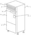
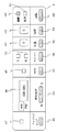
1は器具本体、2は器具本体1上部に形成され複数のルーバー3が設置された送風口、4は器具本体1の正面上部を構成する上面パネル、5は器具本体1の正面下部を構成する下面パネル、6は複数のスイッチが備えられ各種操作指令を行う操作部、7はブレーカー(図示せず)を隠すブレーカーカバーである。
Next, a mist generator according to an embodiment of the present invention will be described with reference to the drawings.
DESCRIPTION OF SYMBOLS 1 is an instrument main body, 2 is the ventilation opening formed in the upper part of the instrument main body 1, and the some louver 3 was installed, 4 is an upper surface panel which comprises the front upper part of the instrument main body 1, and 5 comprises the lower front part of the instrument main body 1 A bottom panel, 6 is an operation unit provided with a plurality of switches and for performing various operation commands, and 7 is a breaker cover for hiding a breaker (not shown).

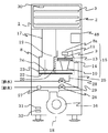
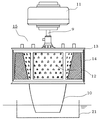
8は上面パネル4内に設置され所定量の水を貯水する貯水室であり、この貯水室8内には、貯水された水に下端を水没させ駆動軸9に軸支された筒状の回転体10が備えられている。   8 is a water storage chamber that is installed in the upper panel 4 and stores a predetermined amount of water. In this water storage chamber 8, a cylindrical rotation supported by the drive shaft 9 with the lower end submerged in the stored water. A body 10 is provided.

前記回転体10は、中空逆円錐形で上方に向かって径が徐々に拡大するものであり、駆動軸9に接続され回転体10を回転駆動させるミストモータ11を駆動させ、回転体10が回転することによる回転の遠心力で貯水室8の水を汲み上げ、回転体10の外壁および内壁を伝わせて水を押し上げて、回転体10の外壁を伝わせて押し上げた水を周囲に飛散させると共に、回転体10の内壁を伝わせて押し上げた水を回転体10の上部に形成された複数の飛散口12から周囲に飛散させる。   The rotating body 10 has a hollow inverted conical shape and gradually increases in diameter upward, and is driven by a mist motor 11 that is connected to the drive shaft 9 and rotationally drives the rotating body 10 to rotate the rotating body 10. The water in the water storage chamber 8 is pumped up by the centrifugal force of rotation by pushing the water along the outer wall and the inner wall of the rotating body 10 and the water pushed up along the outer wall of the rotating body 10 is scattered around. Then, the water pushed up along the inner wall of the rotating body 10 is scattered from the plurality of scattering ports 12 formed in the upper part of the rotating body 10 to the surroundings.

13は回転体10の上部外周に所定間隔を離間させて位置し、回転体10と共に回転する円筒状の多孔体で、該多孔体13には、その全周壁に多数のスリットや金網やパンチングメタル等から成る衝突体としての多孔部14が設置されており、前記回転体10、前記ミストモータ11及び前記多孔体13でミスト発生部15が構成されている。   Reference numeral 13 denotes a cylindrical porous body that is positioned on the outer periphery of the rotating body 10 at a predetermined interval and rotates together with the rotating body 10. The porous body 13 includes a plurality of slits, a metal net, and punching metal on the entire peripheral wall. A porous portion 14 as a collision body made of, for example, is installed, and a mist generating portion 15 is configured by the rotating body 10, the mist motor 11 and the porous body 13.

前記ミスト発生部15を構成するミストモータ11を駆動させ、回転体10を回転させたことで発生する遠心力で貯水室8内の水を汲み上げると共に空気を飛散させ、多孔部14を通過した水滴が破砕されることで、水の粒子を微細化してナノメートル(nm)サイズのナノミストを生成すると共に、水の粒子の微細化によるレナード効果で負イオンを多量に発生させるものである。   Water droplets that have passed through the porous portion 14 by driving the mist motor 11 constituting the mist generating portion 15 and pumping up water in the water storage chamber 8 by centrifugal force generated by rotating the rotating body 10 and scattering air. As a result, the water particles are refined to generate nanometer (nm) sized nanomists, and a large amount of negative ions are generated by the Leonard effect due to the refinement of the water particles.

16は下面パネル5内に設置され所定の回転数で駆動することで室内空気を吸引して器具本体1の上部に吹き出す送風ファン、17は貯水室8と送風口2との間に設置され、貯水室8内で発生したナノミストと負イオンを含む加湿空気を送風口2まで流通させる送風通路であり、前記送風ファン16が所定の回転数で駆動すると、器具本体1低部に形成された吸込口18から吸い込んだ室内空気を器具本体1の上部に向けて送風され、貯水室8に設置された回転体10の上部にある空気流入口8aから送風ファン16によって送風された室内空気が流入し、貯水室8内に流入した室内空気がナノミストと負イオンとを含んだ加湿空気になり、該加湿空気が前記送風通路17内を上昇して送風口2から室内へ送風されることで、加湿空気を室内に供給することが出来るものであり、又室内空気がミスト発生部15を通過することで、貯水に直接ぶつかったり、ミスト発生部15で発生し自重で貯水室8に落下する大きめのナノミストに絡め取られる形で、室内空気中の塵や埃、臭気等が除去され、大きめのナノミストと共に貯水室8の貯水の混入し、室内空気を浄化して綺麗な状態にしてナノミストと負イオンと共に室内に放出されるものである。   16 is installed in the lower panel 5 and is driven at a predetermined number of rotations to suck indoor air and blow it out to the upper part of the instrument body 1. 17 is installed between the water storage chamber 8 and the air outlet 2. A ventilation passage that circulates humidified air containing nanomist and negative ions generated in the water storage chamber 8 to the air outlet 2, and suction formed in the lower portion of the instrument body 1 when the air blowing fan 16 is driven at a predetermined rotational speed. The room air sucked from the mouth 18 is blown toward the upper part of the instrument body 1, and the room air blown by the blower fan 16 flows from the air inlet 8 a at the upper part of the rotating body 10 installed in the water storage chamber 8. The indoor air that has flowed into the water storage chamber 8 becomes humidified air containing nano mist and negative ions, and the humidified air rises in the blowing passage 17 and is blown into the room from the blower opening 2 to humidify the room. Air indoors It can be supplied, and the indoor air passes through the mist generating part 15 so that it directly collides with the water storage or is entangled with a large nano mist generated in the mist generating part 15 and falling into the water storage room 8 by its own weight. Dust, dust, odors, etc. in the indoor air are removed, and the water stored in the water storage chamber 8 is mixed together with the large nanomist, purifying the indoor air to a clean state, and releasing it into the room together with the nanomist and negative ions. It is what is done.

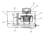
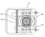
19はミスト発生部15から送風口2までの間で大粒の水滴を除去して貯水室8に戻す気水分離部で、開口率96%の多孔質で、金とニッケルの合金からなる金属フィルタ20により構成されており、更にこの金属フィルタ20は下端を貯水室8の水中に水没させた状態で、ミスト発生部15近傍の送風口2側に備えられており、大粒の水滴が広範囲に拡散する前に除去出来ると共に、除去した水滴の水面への落下音がなくなり静音化されるものである。   19 is an air-water separator that removes large water droplets between the mist generating part 15 and the air outlet 2 and returns it to the water storage chamber 8, and is a porous metal filter made of an alloy of gold and nickel with an opening ratio of 96%. Further, the metal filter 20 is provided on the air blowing port 2 side in the vicinity of the mist generating unit 15 with its lower end submerged in the water in the water storage chamber 8, and large water droplets are diffused over a wide range. In addition to being able to be removed before the removal, the sound of the removed water drops falling on the water surface is eliminated and the sound is reduced.

21はミスト発生部15に供給される水から塵、埃を除去するフィルター部で、回転体10の水没した下端を水中で取り囲むように設置された凹状で、水は通すが細かな塵や埃は通さない耐熱性の金網やスポンジ材で形成され、定期的な清掃が容易に行えるように取り外し容易に設置されているものである。   A filter unit 21 removes dust and dirt from the water supplied to the mist generating unit 15. The filter unit 21 is a concave shape that surrounds the submerged lower end of the rotating body 10 in water. It is made of heat-resistant wire mesh or sponge material that does not pass through and is easily installed so that it can be cleaned regularly.

22は貯水室8内に設置され貯水を加熱する加熱ヒータであり、貯水室8の外壁に設置された貯水温度を検知する貯水温度センサ23で検知される温度が所定温度となるよう、ON/OFF状態を適宜切り替えるものである。   A heater 22 is installed in the water storage chamber 8 and heats the stored water. The heater 22 is turned on / off so that the temperature detected by the water storage temperature sensor 23 that detects the temperature of the water storage installed on the outer wall of the water storage chamber 8 becomes a predetermined temperature. The OFF state is appropriately switched.

24は貯水室8内に設置され、フロートが上下することで水位を検知する水位センサで、貯水室8内の水位が低下して所定水位以下になったらOFF信号を出力し、水位が上昇して所定水位以上になったらON信号を出力し、更に水位が上昇して貯水室8内が満水となったら満水信号を出力するものである。   24 is a water level sensor that is installed in the water storage chamber 8 and detects the water level when the float moves up and down. When the water level in the water storage chamber 8 decreases and falls below a predetermined water level, an OFF signal is output and the water level increases. When the water level exceeds a predetermined level, an ON signal is output. When the water level further rises and the water storage chamber 8 becomes full, a full water signal is output.

25は貯水室8に接続され、貯水室8内に市水を給水する給水管であり、該給水管25の配管途中には、電磁弁を開閉して貯水室8内への給水を制御する給水弁26と、給水圧を所定値まで減圧する減圧弁27とが備えられている。   Reference numeral 25 denotes a water supply pipe connected to the water storage chamber 8 and supplying city water into the water storage chamber 8. During the piping of the water supply pipe 25, an electromagnetic valve is opened and closed to control the water supply into the water storage chamber 8. A water supply valve 26 and a pressure reducing valve 27 for reducing the water supply pressure to a predetermined value are provided.

28は貯水室8底部に接続され、貯水室8内の水を器具本体1外部に排水する硬質塩化ビニル管で構成された排水管であり、該排水管28の配管途中には、電磁弁を開閉して貯水室8内の水の排水を制御する排水弁29が備えれている。   A drain pipe 28 is connected to the bottom of the water storage chamber 8 and is made of a hard vinyl chloride pipe for draining the water in the water storage chamber 8 to the outside of the apparatus main body 1. A drain valve 29 that opens and closes and controls the drainage of water in the water storage chamber 8 is provided.

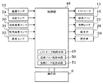
30は送風口2の壁面に設置され、送風口2から室内へ向けて送風される加湿空気の温度を検知する送風温度センサ、31は送風ファン16の近傍に設置され、送風ファン16で吸い込む室内空気の温度を検知する吸気温度センサ、32は前記吸気温度センサ31の近傍に設置され、器具本体1が設置された室内の湿度を検知する湿度センサであり、各センサで検知された温度や湿度に基づいて、ミストモータ11や送風ファン16の回転数を変化させ、加熱ヒータ22のON/OFF状態を切り替えるものである。   Reference numeral 30 denotes a blower temperature sensor that is installed on the wall surface of the blower opening 2 and detects the temperature of humidified air blown from the blower opening 2 into the room, and 31 is installed in the vicinity of the blower fan 16 and is sucked by the blower fan 16. An intake air temperature sensor 32 that detects the temperature of air is a humidity sensor 32 that is installed in the vicinity of the intake air temperature sensor 31 and detects the humidity in the room where the appliance body 1 is installed. The temperature and humidity detected by each sensor Based on the above, the rotational speeds of the mist motor 11 and the blower fan 16 are changed, and the heater 22 is switched between ON / OFF states.

又前記操作部6には、運転開始及び停止を指示する運転スイッチ33と、加熱ヒータ22のON/OFF状態を切り替えることで貯水室8内の貯水温度を変化させ、送風口2から室内に送風される加湿空気に含有可能な水分量の割合を変化させた3段階の加湿レベルと、湿度センサ32で検知された湿度が予め設定された湿度となるよう前記加湿レベルを変化させるオートモードとから選択可能な加湿スイッチ34と、ミストモータ11と送風ファン16との回転数の大小を設定可能な三段階の風量レベルと、湿度センサ32で設定された湿度が予め設定された湿度となるよう前記風量レベルを変化させるオートモードとから選択可能な風量スイッチ35と、加湿空気を室内に供給するミスト運転の開始時間と停止時間とを設定するタイマー切替スイッチ36と、前記加湿スイッチ34及び前記風量スイッチ35での設定に関わらず、消費電力の低いミスト運転であるエコモードを設定するエコモードスイッチ37と、現在時刻を設定する時刻設定スイッチ38と、スイッチを操作することで運転停止以外の動作を禁止するチャイルドロックスイッチ39とが備えられている。   In addition, the operation unit 6 changes the water storage temperature in the water storage chamber 8 by switching the ON / OFF state of the heater 22 and the operation switch 33 for instructing operation start and stop, and air is blown into the room from the air outlet 2. From three stages of humidification levels in which the ratio of the amount of water that can be contained in the humidified air is changed, and an auto mode in which the humidity level is changed so that the humidity detected by the humidity sensor 32 becomes a preset humidity. The humidification switch 34 that can be selected, the three-stage airflow level that can set the number of rotations of the mist motor 11 and the blower fan 16, and the humidity set by the humidity sensor 32 become the preset humidity. An air volume switch 35 that can be selected from an auto mode that changes the air volume level, and a timer that sets a start time and a stop time of mist operation for supplying humidified air into the room Regardless of the setting of the changeover switch 36, the humidifying switch 34 and the air volume switch 35, an eco mode switch 37 for setting an eco mode which is a mist operation with low power consumption, and a time setting switch 38 for setting the current time And a child lock switch 39 for prohibiting operations other than operation stop by operating the switch.

又操作部6の各スイッチ上部には各スイッチに対応したランプが備えられており、運転スイッチ33が操作されたら点灯する運転ランプ40と、ミスト運転が所定時間以上継続したら開始する除菌運転時に点灯する除菌ランプ41と、加湿スイッチ34で設定された加湿レベルを1から3の数値とオートモードを示すAで表示する加湿レベルランプ42と、風量スイッチ35で設定された風量レベルを1から3の数値とオートモードを示すAで表示する風量レベルランプ43と、タイマー切替スイッチ36でミスト運転の開始及び停止が設定されたら、それぞれのランプが点灯するタイマーランプ44と、エコモードスイッチ37が操作されエコモードが設定されたら点灯するエコモードランプ45と、時刻設定スイッチ38で設定された現在時刻を表示する時刻表示パネル46と、チャイルドロックスイッチ39が操作されたら点灯するチャイルドロックランプ47とが備えられている。   Further, lamps corresponding to the respective switches are provided above the respective switches of the operation unit 6, and an operation lamp 40 that is turned on when the operation switch 33 is operated and a sterilization operation that starts when the mist operation continues for a predetermined time or more. The sterilization lamp 41 that is turned on, the humidification level lamp 42 that displays the humidification level set by the humidification switch 34 with a numerical value of 1 to 3 and A indicating the auto mode, and the airflow level set by the airflow switch 35 from 1 When the start / stop of the mist operation is set by the timer switch 36, the timer lamp 44 for turning on each lamp and the eco mode switch 37 are displayed. The eco-mode lamp 45 that is lit when operated and the eco-mode is set, and the current setting set by the time setting switch 38 A time display panel 46 for displaying the time, and a child lock lamp 47 that lights When the child lock switch 39 is operated is provided.

48は各センサで検知された検知値や操作部6上に備えられた各スイッチでの設定内容に基づき、運転内容や弁の開閉を制御するマイコンで構成された制御部であり、ミストモータ11を所定の回転数で駆動させるミストモータ制御手段49と、送風ファン16を所定の回転数で駆動させる送風ファン制御手段50と、加熱ヒータ22のON/OFF状態を切り替えて貯水室8内の水温を制御する加熱ヒータ制御手段51とが備えられている。   Reference numeral 48 denotes a control unit composed of a microcomputer for controlling the operation content and the opening / closing of the valve based on the detection value detected by each sensor and the setting content of each switch provided on the operation unit 6. The mist motor control means 49 for driving the fan at a predetermined rotational speed, the blower fan control means 50 for driving the blower fan 16 at the predetermined rotational speed, and the water temperature in the water storage chamber 8 by switching the ON / OFF state of the heater 22. And a heater control means 51 for controlling the above.

次にこの実施形態での運転開始から終了までの動作について図6のフローチャートに基づいて説明する。
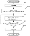
まず、操作部6の運転スイッチ33が操作されたか、もしくはタイマー切替スイッチ36で設定された運転開始時刻になったら、制御部48は、排水弁29を開放して貯水室8内の水を排水し、水位センサ24でOFF信号が検知されたら、給水弁26を開放して貯水室8内を水で洗い流すクリーニング動作を行い、所定時間経過したら排水弁29を閉止することで給水弁26から流入する水を貯水室8内に供給し、水位センサ24でON信号が検知されたら、所定量の水が貯水室8内に供給されたとして給水弁26を閉止する水入替モードを行う(ステップS101)。
Next, the operation from the start to the end of the operation in this embodiment will be described based on the flowchart of FIG.
First, when the operation switch 33 of the operation unit 6 is operated or the operation start time set by the timer changeover switch 36 is reached, the control unit 48 opens the drain valve 29 to drain the water in the water storage chamber 8. When the water level sensor 24 detects an OFF signal, the water supply valve 26 is opened to perform a cleaning operation for washing the water storage chamber 8 with water. After a predetermined time has passed, the drain valve 29 is closed to enter the water supply valve 26. When the water level sensor 24 detects an ON signal, a water replacement mode is performed in which the water supply valve 26 is closed assuming that a predetermined amount of water has been supplied into the water storage chamber 8 (step S101). ).

ステップS101の水入替モードが終了したら、制御部48は、貯水温度センサ23での検知値に基づき、加熱ヒータ22を駆動させて貯水温度Tが吸気温度センサ35で検知される室温と同一値になるまで加熱ヒータ制御手段55で加熱ヒータ22をON状態にして、ミストモータ11及び送風ファン16が所定の回転数となるようミストモータ制御手段53及び送風ファン制御手段54で制御する立ち上げモードを行う(ステップS102)。   When the water replacement mode in step S101 is completed, the control unit 48 drives the heater 22 based on the detection value of the water storage temperature sensor 23 so that the water storage temperature T is equal to the room temperature detected by the intake air temperature sensor 35. Until the heater heater 22 is turned on by the heater control means 55, the start-up mode is controlled by the mist motor control means 53 and the blower fan control means 54 so that the mist motor 11 and the blower fan 16 have a predetermined rotational speed. Perform (step S102).

ステップS102の立ち上げモードが終了したら、制御部48は、加湿スイッチ34及び風量スイッチ35で設定された加湿レベルと風量レベルとに基づいて、ミストモータ11と送風ファン16とが所定の回転数で駆動するようミストモータ制御手段49と送風ファン制御手段50とで回転数を制御し、加熱ヒータ22のON/OFF状態を加熱ヒータ制御手段51で切り替えて制御することで、加湿レベルと風量レベルとに合わせた所定の温度範囲内にするミスト運転を実行する通常運転モードを行う(ステップS103)。   When the start-up mode in step S102 is completed, the control unit 48 causes the mist motor 11 and the blower fan 16 to rotate at a predetermined number of rotations based on the humidification level and the airflow level set by the humidification switch 34 and the airflow switch 35. The mist motor control means 49 and the blower fan control means 50 are controlled so as to drive, and the heater heater 22 is controlled by switching the ON / OFF state of the heater 22 so that the humidification level and the air flow level are controlled. A normal operation mode for executing a mist operation within a predetermined temperature range in accordance with is performed (step S103).

ここで通常運転モードを詳述すると、ミストモータ制御手段49によりミストモータ11を800〜1400rpmの範囲内で回転数を変化させ、また、送風ファン制御手段50で送風ファン16を400〜800rpmの範囲内で回転数を変化させることで、風量レベルに合った回転数にしたミスト運転を行い、更に送風温度センサ30で検知される温度が加湿レベルに合った値となるよう貯水室8内の貯水温度を変化させ、貯水温度センサ23で検知される温度が約30〜40℃の範囲内で推移するように加熱ヒータ22のON/OFF状態を加熱ヒータ制御手段51で切り替えて制御する。   The normal operation mode will now be described in detail. The mist motor control means 49 changes the rotational speed of the mist motor 11 within the range of 800 to 1400 rpm, and the blower fan control means 50 causes the blower fan 16 to change within the range of 400 to 800 rpm. By changing the number of rotations in the mist, the mist operation is performed at the number of rotations that matches the air flow level, and the water stored in the water storage chamber 8 is adjusted so that the temperature detected by the blower temperature sensor 30 becomes a value that matches the humidification level. By changing the temperature, the heater control means 51 switches the ON / OFF state of the heater 22 so that the temperature detected by the water storage temperature sensor 23 changes within the range of about 30 to 40 ° C.

ステップS103の通常運転モードの終了条件を満たしたら、制御部48は、ミストモータ11を停止させてから排水弁29を開弁して貯水室8内の水を排水し、所定時間経過したら給水弁26を開放して貯水室8内を洗浄してから排水弁29を閉止して貯水室8内に所定量だけ貯水する水入替運転を行い、加熱ヒータ22をON状態にして水を加熱することで除菌を行う除菌運転を所定時間行い、所定時間経過後に貯水室8内を冷却して貯水室8内の水を排水する冷却運転を実行するクリーニングモードを行う(ステップS104)。   When the termination condition of the normal operation mode in step S103 is satisfied, the control unit 48 stops the mist motor 11 and then opens the drain valve 29 to drain the water in the water storage chamber 8, and when a predetermined time has elapsed, the water supply valve 26 is opened, the inside of the water storage chamber 8 is washed, the drain valve 29 is closed, and a water replacement operation for storing a predetermined amount of water in the water storage chamber 8 is performed, and the heater 22 is turned on to heat the water. A sterilization operation for performing sterilization is performed for a predetermined time, and after the predetermined time has elapsed, a cleaning mode is performed in which the water storage chamber 8 is cooled to drain the water in the water storage chamber 8 (step S104).

次にこの実施形態におけるクリーニングモードについて、図7のフローチャートに基づいて詳述する。
まず、前記ステップS104のクリーニングモードが開始されたら、制御部48は、ミストモータ11を停止させてから排水弁29を開弁して貯水室8内の水を排水し、8分経過したら、給水弁26を開放して流水によって貯水室8内を洗浄し、20秒経過したら給水弁26を閉止して再度貯水室8内の排水を行い、8分経過したら排水弁29を閉止して給水弁26を開放することで貯水室8内に貯水し、水位センサ24でON信号が検知されたら、給水弁26を閉止する水入替運転を行う(ステップS201)。
Next, the cleaning mode in this embodiment will be described in detail based on the flowchart of FIG.
First, when the cleaning mode of step S104 is started, the control unit 48 stops the mist motor 11 and then opens the drain valve 29 to drain the water in the water storage chamber 8, and when 8 minutes have passed, The valve 26 is opened and the inside of the water storage chamber 8 is washed with running water. When 20 seconds have elapsed, the water supply valve 26 is closed and the water storage chamber 8 is drained again. After 8 minutes, the water discharge valve 29 is closed and the water supply valve is closed. By opening 26, water is stored in the water storage chamber 8, and when an ON signal is detected by the water level sensor 24, a water replacement operation for closing the water supply valve 26 is performed (step S201).

ステップS201で水入替運転を行ったら、制御部48は、加熱ヒータ22をON状態に切り替え、ミストモータ11をミスト運転時の回転数より低い所定の低回転数(例えば、600rpm)で駆動するようミストモータ制御手段49で制御し、更に送風ファン16をミスト運転時の回転数より低い所定の低回転数(例えば、200rpm)で駆動するよう送風ファン制御手段50で制御する除菌運転を開始することで(ステップS202)、貯水室8内の水を混ぜて貯水室8内の水をムラなく高め、送風口2に結露が発生するのを防止する。   After performing the water replacement operation in step S201, the control unit 48 switches the heater 22 to the ON state and drives the mist motor 11 at a predetermined low rotational speed (for example, 600 rpm) lower than the rotational speed during the mist operation. Control is performed by the mist motor control means 49, and further, the sterilization operation controlled by the blower fan control means 50 so as to drive the blower fan 16 at a predetermined low rotational speed (for example, 200 rpm) lower than the rotational speed during the mist operation is started. Thus (step S202), the water in the water storage chamber 8 is mixed to increase the water in the water storage chamber 8 evenly, and condensation is prevented from occurring at the air blowing port 2.

ステップS202で加熱ヒータ22をON状態にしてミストモータ11を駆動させたら、制御部48は、貯水温度Tが65℃を超えたら加熱ヒータ22をOFF状態にして加熱を停止させ、貯水温度Tが63℃未満となったら加熱ヒータ22をON状態にして再度加熱するよう加熱ヒータ制御手段51で加熱ヒータ22を制御し、貯水室8内の貯水温度を除菌可能な温度である65℃付近で保持する加熱動作を行うことで、貯水室8内の貯水を除菌する(ステップS203)。   When the heater 22 is turned on and the mist motor 11 is driven in step S202, the controller 48 turns off the heater 22 to stop heating when the water storage temperature T exceeds 65 ° C. When the temperature is lower than 63 ° C., the heater 22 is controlled by the heater control means 51 so that the heater 22 is turned on again and heated, and the stored water temperature in the water storage chamber 8 is around 65 ° C., which is a sterilizable temperature. By performing the holding heating operation, the water stored in the water storage chamber 8 is sterilized (step S203).

ステップS203で貯水室8内の水を65℃付近に制御する加熱動作を開始したら、制御部48は、加熱動作時に貯水温度センサ23での検知温度が65℃を超えて、加熱ヒータ22がOFF状態に切り替わった最初の時点から経過した時間をカウントし、カウントした時間が10分経過したか判断して(ステップS204)、10分経過していれば、加熱ヒータ22をOFF状態にして除菌運転を終了させ、10分経過していなければ、ステップS203での加熱動作を続行する。   When the heating operation for controlling the water in the water storage chamber 8 to around 65 ° C. is started in step S203, the control unit 48 detects that the temperature detected by the water storage temperature sensor 23 exceeds 65 ° C. during the heating operation, and the heater 22 is turned off. The time elapsed from the first time point when the state is switched to the state is counted, and it is determined whether the counted time has passed 10 minutes (step S204). If 10 minutes have passed, the heater 22 is turned off and sterilized. The operation is terminated, and if 10 minutes have not elapsed, the heating operation in step S203 is continued.

ステップS204で除菌運転が終了したら、制御部48は、給水弁26を開放して貯水室8内への給水を開始し、送風ファン16を所定の回転数で駆動させ、貯水室8内の貯水温度を排水可能な温度まで低下させる冷却運転を行い(ステップS205)、貯水室8内の貯水温度が排水可能な温度まで低下し排水が完了したらクリーニングモードを終了する。   When the sterilization operation is completed in step S204, the control unit 48 opens the water supply valve 26 to start water supply into the water storage chamber 8, and drives the blower fan 16 at a predetermined rotational speed. A cooling operation is performed to lower the water storage temperature to a temperature at which drainage is possible (step S205). When the water storage temperature in the water storage chamber 8 is lowered to a temperature at which water can be drained and drainage is completed, the cleaning mode is terminated.

ステップS104のクリーニングモードが終了したら、制御部48は、送風ファン16が所定の回転数(例えば、800rpm)で駆動するよう送風ファン制御手段50で制御し、貯水室8や送風通路17に送風して乾燥させることで菌の増殖を防止する乾燥モードを行い(ステップS105)、計時手段(図示せず)で送風ファン16の駆動時間が所定時間(例えば、3時間)をカウントしたか判断し、3時間カウントしたら、送風ファン16を停止させて運転を終了する。   When the cleaning mode in step S104 is completed, the control unit 48 controls the blower fan 16 to be driven at a predetermined rotation speed (for example, 800 rpm) by the blower fan control means 50, and blows air to the water storage chamber 8 and the blower passage 17. A drying mode for preventing the growth of bacteria by drying is performed (step S105), and it is determined whether the driving time of the blower fan 16 has counted a predetermined time (for example, 3 hours) by a time measuring means (not shown), After counting for 3 hours, the blower fan 16 is stopped and the operation is terminated.

以上のように、除菌運転時に送風ファン16を駆動させることで、加熱ヒータ22で加熱された貯水室8内の水が蒸発して送風口2まで水蒸気が上昇しても、送風ファン16を駆動させることで送風口2付近の水蒸気を器具本体1の外部に飛ばすことができるため、送風口2を構成する内壁やルーバー3に結露水が付着せず、器具本体1が設置された床面が濡れるのを防止できる。   As described above, by driving the blower fan 16 during the sterilization operation, even if the water in the water storage chamber 8 heated by the heater 22 evaporates and the water vapor rises to the blower port 2, the blower fan 16 is turned on. Since the water vapor in the vicinity of the air outlet 2 can be blown out of the appliance body 1 by being driven, condensed water does not adhere to the inner wall and the louver 3 constituting the air outlet 2, and the floor surface on which the appliance body 1 is installed. Can be prevented from getting wet.

又送風ファン16を200rpmという通常運転モードにおけるミスト運転時の回転数よりも低い所定の低回転数で駆動させることで、貯水室8内で発生して送風口2まで達するナノミストの量を減らすことができ、更にミストモータ11を600rpmという通常運転モードにおけるミスト運転時の回転数よりも低い所定の低回転数で駆動させることで、貯水室8内でのナノミストの発生量を減らしたので、送風ファン16を所定の低回転数で駆動していることと相俟って送風口2の内壁やルーバー3に付着する結露水の量を減少させることができる。   Moreover, the amount of nano mist generated in the water storage chamber 8 and reaching the air outlet 2 is reduced by driving the blower fan 16 at a predetermined low rotational speed lower than the rotational speed during the mist operation in the normal operation mode of 200 rpm. Furthermore, the amount of nano mist generated in the water storage chamber 8 is reduced by driving the mist motor 11 at a predetermined low rotation speed lower than the rotation speed during the mist operation in the normal operation mode of 600 rpm. Coupled with driving the fan 16 at a predetermined low rotational speed, the amount of condensed water adhering to the inner wall of the air outlet 2 and the louver 3 can be reduced.

又送風ファン16を200rpmという所定の低回転数で駆動させているので、加熱ヒータ22によって貯水室8の貯水温度の低下を最小限に抑えることで、貯水室8内の除菌率低下を防止することができると共に、送風ファン16から発生する駆動音や振動について最小限に抑えることができる。   Further, since the blower fan 16 is driven at a predetermined low rotational speed of 200 rpm, the heater 22 prevents the decrease in the water storage temperature of the water storage chamber 8 to the minimum, thereby preventing the sterilization rate in the water storage chamber 8 from decreasing. In addition, the driving sound and vibration generated from the blower fan 16 can be minimized.

又送風ファン16を駆動すると、器具本体1の下部にある吸込口18から送風口2に向けて空気が一方的に流動することで、除菌運転時に貯水室8の空気流入口8aから水蒸気が上昇することがないため、空気流入口8aの上部に設置された制御部48に結露して内部のマイコンが故障するのを防止する。   When the blower fan 16 is driven, air flows unidirectionally from the suction port 18 at the lower part of the instrument body 1 toward the blower port 2, so that water vapor is generated from the air inlet 8 a of the water storage chamber 8 during the sterilization operation. Since it does not rise, it is possible to prevent the internal microcomputer from malfunctioning due to condensation on the control unit 48 installed above the air inlet 8a.

更に前記したように、ミスト発生部15の回転体10の回転で発生したナノミストと負イオンは、送風ファン16の駆動によって流入して来る室内空気により送風口2に運ばれ、ここから室内に放出されて新鮮な気分と心身の爽快感が得られるものであり、又このナノミストと負イオンの発生時には、吸引されて室内空気中に含まれている室内の塵や埃が、貯水に直接ぶつかったり、ミスト発生部15で発生し自重で貯水室8に落下する大きめのナノミストに絡め取られる形で、室内空気中の塵や埃、臭気等が除去され、大きめのナノミストと共に貯水室8の貯水の混入し、室内空気を浄化して綺麗な状態にしてナノミストと負イオンと共に室内に放出されるものであり、そして貯水室8の貯水に混入した塵や埃が水と共にミスト発生部15に供給されようとするが、回転体10の水没した下端は、凹状のフィルター部21によって水中で取り囲まれているので、回転体10に供給される水は常にフィルター部21を通過して、塵や埃が除去された綺麗で清潔な水のみが供給されて、衛生的なナノミストと負イオンが生成され、これが室内に放出されると共に再び室内空気がミスト発生部15に供給されて塵や埃、雑菌、臭気等が除去され、繰り返しこの循環が行われることにより、室内は徐々に綺麗で爽快な空気の状態となり、更に新鮮な気分と心身の爽快感が得られるものである。   Further, as described above, the nano mist and negative ions generated by the rotation of the rotating body 10 of the mist generating unit 15 are carried to the blower opening 2 by the indoor air flowing in by the drive of the blower fan 16, and discharged from here to the room. It is possible to obtain a fresh feeling and a refreshing feeling of the mind and body, and when this nano mist and negative ions are generated, indoor dust and dust that are sucked and contained in the indoor air may directly hit the stored water. In the form of being entangled with the large nanomist generated in the mist generating section 15 and falling into the water storage chamber 8 by its own weight, dust, dust, odor, etc. in the indoor air are removed, and the water stored in the water storage chamber 8 is stored together with the large nanomist. It is mixed and purified to clean the indoor air and released into the room together with nano mist and negative ions. Dust and dust mixed in the water stored in the water storage chamber 8 together with the water is a mist generating section 15. Although the lower end of the rotating body 10 that is submerged is surrounded by the concave filter portion 21 in the water, the water supplied to the rotating body 10 always passes through the filter portion 21 to generate dust and dirt. Only clean and clean water from which dust has been removed is supplied, and sanitary nano mist and negative ions are generated. This is released into the room and the room air is again supplied to the mist generating unit 15 to collect dust and dirt. Various bacteria, odors and the like are removed and this circulation is repeated, so that the room gradually becomes clean and refreshing air, and a fresh feeling and a refreshing feeling of mind and body are obtained.

又フィルター部21は、クリーニングモードの終了後などに定期的に取り外して清掃するなどのメンテナンスを行うことで、除去性能を維持しながら長期に渡って継続して使用出来るものである。   The filter unit 21 can be used continuously over a long period of time while maintaining the removal performance by performing maintenance such as periodic removal and cleaning after the end of the cleaning mode.

更に前記したようにミスト発生部15で発生したナノミストと負イオンの加湿空気は、送風口2から室内に放出されるが、その前に貯水室8内でミスト発生部15の近傍で送風口2側に気水分離部19が備えられ、更にこの気水分離部19を、多孔質の金属フィルタ20で構成したことにより、大粒の水滴を確実に除去することが出来るものであり、又金属フィルタ20を貯水室8内で下端を水中に水没させて備えているので、金属フィルタ20で除去した水滴の貯水室8への戻りがスムーズであり、しかも、水滴が水面に落下してポチャ、ポチャ音を発することがなく静音化されるものであると共に、常に金属フィルタ20が水濡れしており乾燥されず、臭気の発生が防止され、極めて使用勝手が良いものである。   Further, as described above, the humidified air of nano mist and negative ions generated in the mist generating unit 15 is released into the room from the air blowing port 2, but before that, the air blowing port 2 in the vicinity of the mist generating unit 15 in the water storage chamber 8. An air / water separator 19 is provided on the side, and the air / water separator 19 is composed of a porous metal filter 20 so that large water droplets can be reliably removed. 20 is stored in the water storage chamber 8 with its lower end submerged in water, so that the water droplets removed by the metal filter 20 can be smoothly returned to the water storage chamber 8, and the water droplets fall on the surface of the water. The metal filter 20 is always quiet without being emitted, and the metal filter 20 is always wet with water and is not dried, so that the generation of odor is prevented and it is extremely easy to use.

1 器具本体
2 送風口
8 貯水室
10 回転体
11 ミストモータ
13 多孔体
15 ミスト発生部
16 送風ファン
17 送風通路
18 吸込口
19 気水分離部
20 金属フィルタ
DESCRIPTION OF SYMBOLS 1 Instrument main body 2 Blower port 8 Water storage chamber 10 Rotating body 11 Mist motor 13 Porous body 15 Mist generating part 16 Blower fan 17 Blower passage 18 Suction port 19 Air-water separation part 20 Metal filter

Claims (1)

器具本体と、該器具本体内に設置され所定量の水を貯水する貯水室と、該貯水室内の水を回転による遠心力で吸い上げて飛散させて破砕し、ナノミストと負イオンを発生させるミスト発生部と、吸込口から吸引した室内空気をミスト発生部を通すことで空気中の塵、埃を貯水室の水の中に捕集させると共に、浄化された空気をナノミストと負イオンと共に送風口より室内に供給する送風ファンと、前記ミスト発生部から送風口までの間で大粒の水滴を除去して貯水室に戻す気水分離部とを備えたものに於いて、前記気水分離部は多孔質の金属フィルタで構成され、更にこの金属フィルタは下端を貯水室の水中に水没させた状態で、ミスト発生部近傍の送風口側に設けた事を特徴とするミスト発生装置。   A device body, a water storage chamber that is installed in the device body and stores a predetermined amount of water, and mist generation that generates nano mist and negative ions by sucking and scattering the water in the water storage chamber by centrifugal force by rotation. And the room air sucked from the suction port through the mist generating unit, dust and dust in the air are collected in the water of the water storage chamber, and purified air together with nano mist and negative ions from the blower port The air / water separation unit is provided with an air blower fan that is supplied into the room and an air / water separation unit that removes large droplets of water from the mist generation unit to the air blowing port and returns the water droplets to the water storage chamber. A mist generating device characterized in that the mist generating device is provided with a quality metal filter, and further provided on the air outlet side in the vicinity of the mist generating portion in a state where the lower end of the metal filter is submerged in the water of the water storage chamber.
JP2015023771A 2015-02-10 2015-02-10 Mist generator Expired - Fee Related JP6346102B2 (en)

Priority Applications (1)

Application Number Priority Date Filing Date Title
JP2015023771A JP6346102B2 (en) 2015-02-10 2015-02-10 Mist generator

Applications Claiming Priority (1)

Application Number Priority Date Filing Date Title
JP2015023771A JP6346102B2 (en) 2015-02-10 2015-02-10 Mist generator

Publications (2)

Publication Number Publication Date
JP2016148463A true JP2016148463A (en) 2016-08-18
JP6346102B2 JP6346102B2 (en) 2018-06-20

Family

ID=56691695

Family Applications (1)

Application Number Title Priority Date Filing Date
JP2015023771A Expired - Fee Related JP6346102B2 (en) 2015-02-10 2015-02-10 Mist generator

Country Status (1)

Country Link
JP (1) JP6346102B2 (en)

Cited By (2)

* Cited by examiner, † Cited by third party
Publication number Priority date Publication date Assignee Title
JP2018204818A (en) * 2017-05-31 2018-12-27 株式会社コロナ Humidifier
JP2019032122A (en) * 2017-08-09 2019-02-28 株式会社コロナ Humidifier

Citations (3)

* Cited by examiner, † Cited by third party
Publication number Priority date Publication date Assignee Title
JPH0252026U (en) * 1988-09-30 1990-04-13
JP2001304636A (en) * 2000-04-20 2001-10-31 Matsushita Seiko Co Ltd Negative ion generator
JP2003130404A (en) * 2001-10-25 2003-05-08 Horizon:Kk Anion generator

Patent Citations (3)

* Cited by examiner, † Cited by third party
Publication number Priority date Publication date Assignee Title
JPH0252026U (en) * 1988-09-30 1990-04-13
JP2001304636A (en) * 2000-04-20 2001-10-31 Matsushita Seiko Co Ltd Negative ion generator
JP2003130404A (en) * 2001-10-25 2003-05-08 Horizon:Kk Anion generator

Cited By (2)

* Cited by examiner, † Cited by third party
Publication number Priority date Publication date Assignee Title
JP2018204818A (en) * 2017-05-31 2018-12-27 株式会社コロナ Humidifier
JP2019032122A (en) * 2017-08-09 2019-02-28 株式会社コロナ Humidifier

Also Published As

Publication number Publication date
JP6346102B2 (en) 2018-06-20

Similar Documents

Publication Publication Date Title
JP6282935B2 (en) Mist generator
JP6204265B2 (en) Mist generator
JP2016003806A (en) Mist generating device
JP6591936B2 (en) Humidifier
JP6060023B2 (en) Mist generator
JP6925293B2 (en) Humidified air purifier
JP6630235B2 (en) Humidifier
JP6495081B2 (en) Mist generator
JP2014217810A (en) Mist generating device
JP6467251B2 (en) Humidifier
JP6346102B2 (en) Mist generator
JP6352829B2 (en) Mist generator
JP6806595B2 (en) Mist generator
JP2014204864A (en) Mist generating device
JP2018124032A (en) Mist generation device
JP6006164B2 (en) Mist generator
JP6082619B2 (en) Mist generator
JP6657000B2 (en) Mist generator
JP6925291B2 (en) Humidifier
JP2013019652A (en) Air cleaning deodorizing device
JP5681056B2 (en) Air purifier deodorizer
JP6510955B2 (en) Humidifier
JP7040958B2 (en) Humidifier
JP2016148489A (en) Mist generator
JP6510813B2 (en) Mist generator

Legal Events

Date Code Title Description
A621 Written request for application examination

Free format text: JAPANESE INTERMEDIATE CODE: A621

Effective date: 20170719

A977 Report on retrieval

Free format text: JAPANESE INTERMEDIATE CODE: A971007

Effective date: 20180510

TRDD Decision of grant or rejection written
A01 Written decision to grant a patent or to grant a registration (utility model)

Free format text: JAPANESE INTERMEDIATE CODE: A01

Effective date: 20180522

A61 First payment of annual fees (during grant procedure)

Free format text: JAPANESE INTERMEDIATE CODE: A61

Effective date: 20180524

R150 Certificate of patent or registration of utility model

Ref document number: 6346102

Country of ref document: JP

Free format text: JAPANESE INTERMEDIATE CODE: R150

R250 Receipt of annual fees

Free format text: JAPANESE INTERMEDIATE CODE: R250

LAPS Cancellation because of no payment of annual fees