JP2016143665A - Electric contact means and electrical cable assembly for automotive industry - Google Patents
Electric contact means and electrical cable assembly for automotive industry Download PDFInfo
- Publication number
- JP2016143665A JP2016143665A JP2015249597A JP2015249597A JP2016143665A JP 2016143665 A JP2016143665 A JP 2016143665A JP 2015249597 A JP2015249597 A JP 2015249597A JP 2015249597 A JP2015249597 A JP 2015249597A JP 2016143665 A JP2016143665 A JP 2016143665A
- Authority
- JP
- Japan
- Prior art keywords
- contact
- electrical
- springs
- section
- contact means
- Prior art date
- Legal status (The legal status is an assumption and is not a legal conclusion. Google has not performed a legal analysis and makes no representation as to the accuracy of the status listed.)
- Granted
Links
- 238000009826 distribution Methods 0.000 claims abstract description 18
- RYGMFSIKBFXOCR-UHFFFAOYSA-N Copper Chemical compound [Cu] RYGMFSIKBFXOCR-UHFFFAOYSA-N 0.000 claims abstract description 12
- 229910052782 aluminium Inorganic materials 0.000 claims abstract description 12
- XAGFODPZIPBFFR-UHFFFAOYSA-N aluminium Chemical compound [Al] XAGFODPZIPBFFR-UHFFFAOYSA-N 0.000 claims abstract description 12
- 229910052802 copper Inorganic materials 0.000 claims abstract description 12
- 239000010949 copper Substances 0.000 claims abstract description 12
- 230000013011 mating Effects 0.000 claims description 30
- 239000000463 material Substances 0.000 claims description 13
- 238000003491 array Methods 0.000 claims description 9
- 230000007704 transition Effects 0.000 claims description 7
- 238000013461 design Methods 0.000 claims description 6
- 238000003466 welding Methods 0.000 claims description 4
- 230000007423 decrease Effects 0.000 claims 2
- 239000004020 conductor Substances 0.000 description 27
- 238000002788 crimping Methods 0.000 description 17
- 229910052751 metal Inorganic materials 0.000 description 10
- 239000002184 metal Substances 0.000 description 10
- 238000003780 insertion Methods 0.000 description 7
- 230000037431 insertion Effects 0.000 description 7
- 238000009413 insulation Methods 0.000 description 4
- 241000446313 Lamella Species 0.000 description 3
- 238000004891 communication Methods 0.000 description 3
- 230000008878 coupling Effects 0.000 description 3
- 238000010168 coupling process Methods 0.000 description 3
- 238000005859 coupling reaction Methods 0.000 description 3
- 238000009429 electrical wiring Methods 0.000 description 3
- 238000005516 engineering process Methods 0.000 description 3
- 229910001092 metal group alloy Inorganic materials 0.000 description 3
- 230000000712 assembly Effects 0.000 description 2
- 238000000429 assembly Methods 0.000 description 2
- 230000005540 biological transmission Effects 0.000 description 2
- 230000000295 complement effect Effects 0.000 description 2
- 230000006835 compression Effects 0.000 description 2
- 238000007906 compression Methods 0.000 description 2
- 230000000694 effects Effects 0.000 description 2
- 238000010292 electrical insulation Methods 0.000 description 2
- 238000005304 joining Methods 0.000 description 2
- WABPQHHGFIMREM-UHFFFAOYSA-N lead(0) Chemical compound [Pb] WABPQHHGFIMREM-UHFFFAOYSA-N 0.000 description 2
- 210000001331 nose Anatomy 0.000 description 2
- 210000002105 tongue Anatomy 0.000 description 2
- 230000006978 adaptation Effects 0.000 description 1
- 238000010276 construction Methods 0.000 description 1
- 230000001419 dependent effect Effects 0.000 description 1
- 238000010586 diagram Methods 0.000 description 1
- 238000004870 electrical engineering Methods 0.000 description 1
- 230000007613 environmental effect Effects 0.000 description 1
- 238000000034 method Methods 0.000 description 1
- 238000012986 modification Methods 0.000 description 1
- 230000004048 modification Effects 0.000 description 1
- 238000003825 pressing Methods 0.000 description 1
- 239000002994 raw material Substances 0.000 description 1
- 230000003068 static effect Effects 0.000 description 1
Images


Classifications
-
- H—ELECTRICITY
- H01—ELECTRIC ELEMENTS
- H01R—ELECTRICALLY-CONDUCTIVE CONNECTIONS; STRUCTURAL ASSOCIATIONS OF A PLURALITY OF MUTUALLY-INSULATED ELECTRICAL CONNECTING ELEMENTS; COUPLING DEVICES; CURRENT COLLECTORS
- H01R13/00—Details of coupling devices of the kinds covered by groups H01R12/70 or H01R24/00 - H01R33/00
- H01R13/02—Contact members
- H01R13/04—Pins or blades for co-operation with sockets
- H01R13/05—Resilient pins or blades
-
- H—ELECTRICITY
- H01—ELECTRIC ELEMENTS
- H01R—ELECTRICALLY-CONDUCTIVE CONNECTIONS; STRUCTURAL ASSOCIATIONS OF A PLURALITY OF MUTUALLY-INSULATED ELECTRICAL CONNECTING ELEMENTS; COUPLING DEVICES; CURRENT COLLECTORS
- H01R13/00—Details of coupling devices of the kinds covered by groups H01R12/70 or H01R24/00 - H01R33/00
- H01R13/02—Contact members
- H01R13/10—Sockets for co-operation with pins or blades
- H01R13/11—Resilient sockets
- H01R13/113—Resilient sockets co-operating with pins or blades having a rectangular transverse section
-
- H—ELECTRICITY
- H01—ELECTRIC ELEMENTS
- H01R—ELECTRICALLY-CONDUCTIVE CONNECTIONS; STRUCTURAL ASSOCIATIONS OF A PLURALITY OF MUTUALLY-INSULATED ELECTRICAL CONNECTING ELEMENTS; COUPLING DEVICES; CURRENT COLLECTORS
- H01R13/00—Details of coupling devices of the kinds covered by groups H01R12/70 or H01R24/00 - H01R33/00
- H01R13/02—Contact members
- H01R13/22—Contacts for co-operating by abutting
- H01R13/24—Contacts for co-operating by abutting resilient; resiliently-mounted
- H01R13/2457—Contacts for co-operating by abutting resilient; resiliently-mounted consisting of at least two resilient arms contacting the same counterpart
-
- H—ELECTRICITY
- H01—ELECTRIC ELEMENTS
- H01R—ELECTRICALLY-CONDUCTIVE CONNECTIONS; STRUCTURAL ASSOCIATIONS OF A PLURALITY OF MUTUALLY-INSULATED ELECTRICAL CONNECTING ELEMENTS; COUPLING DEVICES; CURRENT COLLECTORS
- H01R4/00—Electrically-conductive connections between two or more conductive members in direct contact, i.e. touching one another; Means for effecting or maintaining such contact; Electrically-conductive connections having two or more spaced connecting locations for conductors and using contact members penetrating insulation
- H01R4/02—Soldered or welded connections
- H01R4/029—Welded connections
-
- H—ELECTRICITY
- H01—ELECTRIC ELEMENTS
- H01R—ELECTRICALLY-CONDUCTIVE CONNECTIONS; STRUCTURAL ASSOCIATIONS OF A PLURALITY OF MUTUALLY-INSULATED ELECTRICAL CONNECTING ELEMENTS; COUPLING DEVICES; CURRENT COLLECTORS
- H01R4/00—Electrically-conductive connections between two or more conductive members in direct contact, i.e. touching one another; Means for effecting or maintaining such contact; Electrically-conductive connections having two or more spaced connecting locations for conductors and using contact members penetrating insulation
- H01R4/10—Electrically-conductive connections between two or more conductive members in direct contact, i.e. touching one another; Means for effecting or maintaining such contact; Electrically-conductive connections having two or more spaced connecting locations for conductors and using contact members penetrating insulation effected solely by twisting, wrapping, bending, crimping, or other permanent deformation
-
- H—ELECTRICITY
- H01—ELECTRIC ELEMENTS
- H01R—ELECTRICALLY-CONDUCTIVE CONNECTIONS; STRUCTURAL ASSOCIATIONS OF A PLURALITY OF MUTUALLY-INSULATED ELECTRICAL CONNECTING ELEMENTS; COUPLING DEVICES; CURRENT COLLECTORS
- H01R4/00—Electrically-conductive connections between two or more conductive members in direct contact, i.e. touching one another; Means for effecting or maintaining such contact; Electrically-conductive connections having two or more spaced connecting locations for conductors and using contact members penetrating insulation
- H01R4/28—Clamped connections, spring connections
- H01R4/48—Clamped connections, spring connections utilising a spring, clip, or other resilient member
- H01R4/4809—Clamped connections, spring connections utilising a spring, clip, or other resilient member using a leaf spring to bias the conductor toward the busbar
-
- H—ELECTRICITY
- H01—ELECTRIC ELEMENTS
- H01R—ELECTRICALLY-CONDUCTIVE CONNECTIONS; STRUCTURAL ASSOCIATIONS OF A PLURALITY OF MUTUALLY-INSULATED ELECTRICAL CONNECTING ELEMENTS; COUPLING DEVICES; CURRENT COLLECTORS
- H01R4/00—Electrically-conductive connections between two or more conductive members in direct contact, i.e. touching one another; Means for effecting or maintaining such contact; Electrically-conductive connections having two or more spaced connecting locations for conductors and using contact members penetrating insulation
- H01R4/58—Electrically-conductive connections between two or more conductive members in direct contact, i.e. touching one another; Means for effecting or maintaining such contact; Electrically-conductive connections having two or more spaced connecting locations for conductors and using contact members penetrating insulation characterised by the form or material of the contacting members
-
- H—ELECTRICITY
- H01—ELECTRIC ELEMENTS
- H01R—ELECTRICALLY-CONDUCTIVE CONNECTIONS; STRUCTURAL ASSOCIATIONS OF A PLURALITY OF MUTUALLY-INSULATED ELECTRICAL CONNECTING ELEMENTS; COUPLING DEVICES; CURRENT COLLECTORS
- H01R2201/00—Connectors or connections adapted for particular applications
- H01R2201/26—Connectors or connections adapted for particular applications for vehicles
-
- H—ELECTRICITY
- H01—ELECTRIC ELEMENTS
- H01R—ELECTRICALLY-CONDUCTIVE CONNECTIONS; STRUCTURAL ASSOCIATIONS OF A PLURALITY OF MUTUALLY-INSULATED ELECTRICAL CONNECTING ELEMENTS; COUPLING DEVICES; CURRENT COLLECTORS
- H01R4/00—Electrically-conductive connections between two or more conductive members in direct contact, i.e. touching one another; Means for effecting or maintaining such contact; Electrically-conductive connections having two or more spaced connecting locations for conductors and using contact members penetrating insulation
- H01R4/10—Electrically-conductive connections between two or more conductive members in direct contact, i.e. touching one another; Means for effecting or maintaining such contact; Electrically-conductive connections having two or more spaced connecting locations for conductors and using contact members penetrating insulation effected solely by twisting, wrapping, bending, crimping, or other permanent deformation
- H01R4/18—Electrically-conductive connections between two or more conductive members in direct contact, i.e. touching one another; Means for effecting or maintaining such contact; Electrically-conductive connections having two or more spaced connecting locations for conductors and using contact members penetrating insulation effected solely by twisting, wrapping, bending, crimping, or other permanent deformation by crimping
- H01R4/183—Electrically-conductive connections between two or more conductive members in direct contact, i.e. touching one another; Means for effecting or maintaining such contact; Electrically-conductive connections having two or more spaced connecting locations for conductors and using contact members penetrating insulation effected solely by twisting, wrapping, bending, crimping, or other permanent deformation by crimping for cylindrical elongated bodies, e.g. cables having circular cross-section
Abstract
Description
本発明は、特に自動車産業用の銅製またはアルミニウム製ケーブルのための、電力連絡用の電気コンタクト手段、好ましくは雌型コンタクト手段に関する。さらに、本発明は、特に自動車産業用の銅製またはアルミニウム製ケーブルのための、雌型コンタクト手段を好ましくは備える、電力連絡部用の電気ケーブル組立体に関する。 The present invention relates to electrical contact means, preferably female contact means, for power communication, particularly for copper or aluminum cables for the automotive industry. Furthermore, the present invention relates to an electrical cable assembly for a power connection, preferably comprising female contact means, particularly for copper or aluminum cables for the automotive industry.
電気技術(電気機器;電子工学、電気工学、電力工学、等)の分野では、多数の電気的接続部、特に電気プラグ接続部が知られている。これらは、電流、電圧、周波数、および/またはデータレートの可能な最大の帯域幅で、電流、電圧、および/または信号を伝送する役割を果たす。特に自動車産業における、低、中、もしくは高電圧、および/または低、中、もしくは高電流の技術において、そのような接続部は、熱を帯びた、汚染された、湿気のある、および/または化学的に攻撃的な環境条件において、場合によっては比較的長い時間の期間の後で一時的に、または永久的に、電力、信号、および/またはデータの問題のない伝送を確保しなければならない。そのような接続部に関する用途の範囲が広いことに起因して、特別に構成された電気コンタクト、コンタクト手段、および/または端子が、特にたとえばプラグ接続部において電気プラグコンタクト手段としての役割を果たす圧着コンタクト手段が、多数知られている。 In the field of electrical technology (electrical equipment; electronic engineering, electrical engineering, power engineering, etc.), many electrical connections, in particular electrical plug connections, are known. They serve to transmit current, voltage and / or signal with the maximum possible bandwidth of current, voltage, frequency and / or data rate. In low, medium or high voltage and / or low, medium or high current technologies, especially in the automotive industry, such connections are hot, contaminated, damp and / or In chemically aggressive environmental conditions, there must be a problem-free transmission of power, signals and / or data, sometimes temporarily or permanently after a relatively long period of time . Due to the wide range of applications for such connections, specially configured electrical contacts, contact means and / or terminals serve as electrical plug contact means, particularly in plug connections, for example. Many contact means are known.
たとえば端子コンタクトとしてまたはプラグインスリーブとして構成されるそのようなコンタクト手段を、電気ケーブル組立体を構成する電気ケーブル、電気配線ハーネス等に圧着することができる。コンタクト手段または圧着コンタクト手段を、電気機器、電子機器、または電気光学機器の電気デバイスのところに/内に、強固に設置することもできる。コンタクト手段または圧着コンタクト手段は、ケーブルまたは配線ハーネスのところに配置される場合、多くの場合、プラグコンタクト手段、またはカプリングもしくはプラグと呼ばれる。コンタクト手段または圧着コンタクト手段が、電気デバイス、電子デバイス、または電気光学デバイスのところに/内に配置される場合、通常は、レセプタクル、ソケットコンタクト手段またはユニット、たとえばパネルジャック、ヘッダ、インターフェース、等と呼ばれる。 For example, such contact means configured as terminal contacts or as plug-in sleeves can be crimped to electrical cables, electrical wiring harnesses, etc. that comprise the electrical cable assembly. The contact means or crimp contact means can also be firmly installed at / in the electrical device of the electrical equipment, electronic equipment or electro-optic equipment. When contact means or crimp contact means are placed at a cable or wiring harness, they are often referred to as plug contact means, or couplings or plugs. When the contact means or crimp contact means are placed at / into an electrical device, electronic device, or electro-optic device, usually with a receptacle, socket contact means or unit, such as a panel jack, header, interface, etc. be called.
永久的な電気的接続部に加えて、電気ケーブルと圧着コンタクト手段の導体圧着区間との間に、コンタクト手段によって永久的な機械的接続部を設ける必要がある。ケーブルを電気的におよび機械的に接続するために、圧着コンタクト手段は、導体圧着区間、および加えて通常は絶縁圧着区間を備える。小型化、およびコストを低く維持するための取組みにより、製造者は、たとえば電力連絡の分野において、広い範囲の適用可能性を提供する、さらに小さいコンタクト手段を生産することを余儀なくされている。この文脈において、単純な構成および同時に良好な電気特性を有する、高価でないコンタクト手段に対する要請が高まっている。さらに、低い伝送抵抗および十分な堅牢性が望ましい。 In addition to the permanent electrical connection, it is necessary to provide a permanent mechanical connection by means of the contact means between the electrical cable and the conductor crimping section of the crimp contact means. In order to connect the cables electrically and mechanically, the crimp contact means comprises a conductor crimping section, and in addition usually an insulating crimping section. Due to the miniaturization and efforts to keep costs low, manufacturers are forced to produce smaller contact means that provide a wide range of applicability, for example, in the field of power communication. In this context, there is a growing demand for inexpensive contact means with a simple construction and at the same time good electrical properties. Furthermore, low transmission resistance and sufficient robustness are desirable.
自動車産業用の電力連絡の分野では、円形の高電圧および/または高電流のコンタクト手段または端子のみが知られている。これらは圧着コンタクト手段としてはさらに設計されていないが、圧着コンタクト手段であれば、圧延金属条片から容易に打ち抜くことができる。矩形の高電圧および/または高電流コンタクト手段では、多くの金属線条加工(filigree)コンタクト薄板によって、電気連絡部が設けられる。この場合、全てのコンタクト薄板は、同じ設計を有し、長手方向の両方の端部部分のところでコンタクトケージに結着される。コンタクト手段におけるコンタクト薄板の位置に起因して、コンタクト薄板あたりのアンペア数は、コンタクト手段の使用中において異なっている。そのようなコンタクト手段を用いては、バランスのとれた電流分布は不可能である。さらに、多くの金属線条加工コンタクト薄板は、堅牢でない、損傷し易いコンタクト手段をもたらす。 In the field of power communication for the automotive industry, only circular high voltage and / or high current contact means or terminals are known. These are not further designed as crimp contact means, but if they are crimp contact means, they can be easily punched from the rolled metal strip. In a rectangular high voltage and / or high current contact means, the electrical connection is provided by a number of metal filament contact sheets. In this case, all the contact lamellas have the same design and are attached to the contact cage at both longitudinal ends. Due to the position of the contact sheet in the contact means, the amperage per contact sheet varies during use of the contact means. With such contact means, a balanced current distribution is not possible. In addition, many metal striated contact sheets provide a non-robust, fragile contact means.
自動車産業用の銅製またはアルミニウム製ケーブルのための、電力連絡部用の改善された電気コンタクト手段、好ましくは改善された雌型コンタクト手段を提供することが、本発明の目的である。さらに、それに従って改善された電気ケーブル組立体を提供することが、本発明の目的である。この文脈では、自動車用途のための圧着コンタクト手段として好ましくは構成された中電圧もしくは高電圧および/または中電流もしくは高電流のコンタクト手段または端子が、好ましくは規定されることになろう。さらに、好ましくは矩形の電気コンタクト手段が規定されることになり、この場合、このコンタクト手段を通してバランスのとれた電流分布が、主としてまたは本質的に可能である。さらに、現状の技術における多くの金属線条加工コンタクト薄板は、以下でコンタクトばねとして設計されている堅牢なコンタクト薄板によって、置き換え可能となるであろう。 It is an object of the present invention to provide an improved electrical contact means, preferably an improved female contact means, for a power connection for copper or aluminum cables for the automotive industry. Furthermore, it is an object of the present invention to provide an improved electrical cable assembly accordingly. In this context, medium voltage or high voltage and / or medium current or high current contact means or terminals preferably configured as crimp contact means for automotive applications will preferably be defined. Furthermore, preferably a rectangular electrical contact means will be defined, in which case a balanced current distribution through this contact means is possible mainly or essentially. In addition, many metal strip processed contact sheets in the state of the art would be replaceable by robust contact sheets that are designed below as contact springs.
本発明の目的は、請求項1に記載の、自動車産業用の銅製またはアルミニウム製ケーブルのための、電力連絡部用の電気コンタクト手段、好ましくは雌型コンタクト手段によって;および、請求項12に記載の、自動車産業用の銅製またはアルミニウム製ケーブルのための、雌型コンタクト手段を好ましくは備える、電力連絡部用の電気ケーブル組立体によって、解決される。ここでは、電気ケーブル組立体は、独創的な電気コンタクト手段、好ましくは独創的な雌型コンタクト手段を備える。本発明の有利な実施形態、追加の特徴、および/または追加の利点は、従属請求項において、および本発明の以下の説明において規定される。
The object of the present invention is by means of electrical contact means, preferably female contact means, for a power connection for a copper or aluminum cable for the automotive industry according to
本発明による電気コンタクト手段は、電気対合コンタクト手段によって電気的に接触可能な電気コンタクト区間を備え、このコンタクト区間は、対合コンタクト手段に電気的に接触するための複数または多数のコンタクトばねを備える。この電気コンタクト手段において、コンタクト区間は、コンタクト手段を通してバランスのとれた電流分布を得るための異なる幾何学的形状を有する、少なくとも2つの、好ましくは少なくとも3つ、4つ、またはこれより多くのコンタクトばねを備える。すなわち、たとえば多数のコンタクトばねのうちの、少なくとも複数、大部分、または全てを通して、バランスのとれた電流分布を得るために、これらのコンタクトばねの各々の電気抵抗率が、これらのコンタクトばねおよびそれぞれのコンタクトばねの脇の(オフ側の)コンタクト手段を通る抵抗経路が主としてまたは本質的に等しくなるような方法で、適合される。 The electrical contact means according to the invention comprises an electrical contact section that can be electrically contacted by the electrical mating contact means, which contact section comprises a plurality or multiple contact springs for electrical contact with the mating contact means. Prepare. In this electrical contact means, the contact section has at least 2, preferably at least 3, 4 or more contacts having different geometric shapes for obtaining a balanced current distribution through the contact means. A spring is provided. That is, for example, to obtain a balanced current distribution through at least a plurality, most, or all of a number of contact springs, the electrical resistivity of each of these contact springs is determined by the contact springs and the respective Are adapted in such a way that the resistance path through the (off-side) contact means beside the contact spring is essentially or essentially equal.
さらに、本発明による電気コンタクト手段は、電気対合コンタクト手段によって電気的に接触可能な電気コンタクト区間を備え、この場合、コンタクト区間は、対合コンタクト手段に電気的に接触するための、多数のコンタクトばねを備える。この場合、多数のコンタクトばねのうちの、少なくとも複数、または大部分を通してバランスのとれた電流分布を得るために、これらの複数のコンタクトばねの各々の電気抵抗率が、これらのコンタクトばねおよびそれぞれのコンタクトばねの脇のコンタクト手段を通る抵抗経路が主としてまたは本質的に等しくなるような方法で、適合される。 Furthermore, the electrical contact means according to the invention comprises an electrical contact section that can be electrically contacted by the electrical mating contact means, in which case the contact section has a number of electrical contacts for electrical contact with the mating contact means. A contact spring is provided. In this case, in order to obtain a balanced current distribution through at least some or most of the multiple contact springs, the electrical resistivity of each of the plurality of contact springs is determined by the contact springs and the respective Adapted in such a way that the resistance path through the contact means beside the contact spring is mainly or essentially equal.
このことは、コンタクトばねのうちの複数、大部分、または全てを通して、バランスのとれた電流分布を得るために、少なくとも複数または大部分のコンタクトばね、好ましくは全てのコンタクトばねに関する抵抗率を、互いに調整する必要があることを意味する。ここでは、コンタクト区間は、少なくとも2つの、好ましくは少なくとも3つ、4つ、またはこれより多くのコンタクトばねを備え、各々が、コンタクト手段を通してバランスのとれた電流分布を得るために、たとえば異なる幾何学形状を好ましくは有する。たとえば、それぞれのコンタクトばねの幾何学形状、すなわち幅、長さ、および/または厚さは、電気経路に沿ったバルク抵抗が、その他のコンタクトばねと一致して、コンタクト区間全体またはコンタクト手段(該当する場合、その一部)にわたって等しくなるような方法で設計される。 This means that the resistivity for at least some or most of the contact springs, preferably all of the contact springs, is obtained from each other in order to obtain a balanced current distribution through the plurality, most or all of the contact springs. It means that it needs to be adjusted. Here, the contact section comprises at least two, preferably at least three, four or more contact springs, each of which has, for example, a different geometry in order to obtain a balanced current distribution through the contact means. Preferably has a geometric shape. For example, the geometry of each contact spring, i.e., width, length, and / or thickness, is such that the bulk resistance along the electrical path matches the other contact springs, or the entire contact section or contact means (as applicable). If so, it will be designed in such a way that it will be equal over part).
本発明によれば、コンタクト区間の設計は、複数のコンタクトばねおよびコンタクト区間を通る電流のための経路の電気抵抗率の合計が、互いの間で主としてまたは本質的に等しくなるような方法で構成される。ここでは、それぞれのコンタクトばねのそれぞれの電気抵抗率、および対応する1つの大容積部分の電気抵抗率または複数の対応する大容積部分の電気抵抗率が、複数のコンタクトばねを通る各電流経路に対して好ましくは本質的に決定される。このことはたとえば、本発明により、複数のコンタクトばねの各コンタクトばねに対して、それぞれのコンタクトばねおよびコンタクト区間またはコンタクト手段を通って流れることのできる電流に対して等しい電気抵抗経路をそれぞれ使用して、複数のコンタクトばねの設計のバランスをとるように、少なくとも1つの幾何学的寸法が選択されることを意味する。 According to the present invention, the design of the contact section is configured in such a way that the sum of the electrical resistivity of the paths for the current through the plurality of contact springs and contact sections is mainly or essentially equal between each other. Is done. Here, the respective electrical resistivity of each contact spring and the corresponding one large volume electrical resistivity or the plurality of corresponding large volume electrical resistivities are in each current path through the multiple contact springs. On the other hand, it is preferably determined essentially. This is the case, for example, according to the invention, for each contact spring of a plurality of contact springs, each using an equal resistance path for the current that can flow through the respective contact spring and contact section or contact means. Thus, it is meant that at least one geometric dimension is selected to balance the design of the multiple contact springs.
これらのコンタクトばねおよびそれぞれのコンタクトばねの脇のコンタクト手段を通る概ねもしくは本質的に等しい抵抗経路を保証するために、ならびに/または、これらのコンタクトばねを通って流れることのできる概ねもしくは本質的に等しい電流割合を保証するために、これらのコンタクトばねの少なくとも1つの寸法、好ましくはこれらのコンタクトばねの幅および/または長さが、コンタクト区間またはコンタクト手段におけるこれらのコンタクトばねの位置に関して適合される。さらに、これらのコンタクトばねの少なくとも1つの寸法、好ましくはこれらのコンタクトばねの幅および/または長さを、問題となっているその他のコンタクトばねの寸法に関して適合させることができる。 In order to ensure a generally or essentially equal resistance path through the contact springs and the contact means beside each contact spring and / or in general or essentially which can flow through these contact springs. In order to ensure an equal current ratio, at least one dimension of these contact springs, preferably the width and / or length of these contact springs, is adapted with respect to the position of these contact springs in the contact section or contact means. . Furthermore, at least one dimension of these contact springs, preferably the width and / or length of these contact springs, can be adapted with respect to the dimensions of the other contact springs in question.
コンタクト区間における複数のコンタクトばねの位置に起因する、これらの間の抵抗に関する違いを補償するために、各コンタクトばねの寸法は、これらのコンタクトばねの各々ならびにそれぞれのコンタクトばねの脇のコンタクト区間および/またはコンタクト手段を通って流れることのできる電流に関する電気抵抗率が、主としてまたは本質的に等しくなるような方法で、好ましくは選択される。すなわち、問題となっている各コンタクトばねおよびその対応する1つの大容積部分または複数の大容積部分の電気抵抗率の合計が、主としてまたは本質的に等しくなる。 In order to compensate for the difference in resistance between them due to the position of the multiple contact springs in the contact section, the size of each contact spring is determined by the contact section beside each of these contact springs and each contact spring and The electrical resistivity with respect to the current that can flow through the contact means is preferably selected in such a way that it is mainly or essentially equal. That is, the sum of the electrical resistivity of each contact spring in question and its corresponding mass or masses is primarily or essentially equal.
本発明によれば、特にそれぞれのコンタクト区間への接続部とそれぞれの電気コンタクト領域との間で、複数のコンタクトばねは、互いの間で異なる幅を備え、かつ/または、複数のコンタクトばねは、互いの間で異なる長さを備える。さらに、本発明によれば、コンタクト区間は、別のコンタクトばねよりも小さい幅を有する、少なくとも1つのコンタクトばねを備える。この場合、より小さい幅を有するコンタクトばねは、より大きい幅を有するコンタクトばねよりも、コンタクト手段の移行区間および/または接続区間(導電体)の近くに配置される。より幅広のコンタクトばねは、より小さいコンタクトばねよりも高い接触力を有するので、コンタクトばねに関して一定の法線力を得るためには、それらの長さを大きくする必要がある。 According to the invention, in particular between the connection to the respective contact section and the respective electrical contact region, the contact springs have different widths between each other and / or the contact springs are , With different lengths between each other. Furthermore, according to the invention, the contact section comprises at least one contact spring having a smaller width than another contact spring. In this case, the contact spring with the smaller width is arranged closer to the transition section and / or the connection section (conductor) of the contact means than the contact spring with the larger width. Since wider contact springs have a higher contact force than smaller contact springs, their length needs to be increased to obtain a constant normal force with respect to the contact spring.
コンタクト区間は、別のコンタクトばねよりも短い長さを有する、少なくとも1つのコンタクトばねを備え得る。ここでは、好ましくは、より短い長さを有するコンタクトばねは、より長い長さを有するコンタクトばねよりも、移行区間および/または接続区間(導電体)の近くに配置される。さらに、より短い長さを有するコンタクトばねは、より長い長さを有するコンタクトばねよりも小さい幅を好ましくは有し、そしてこのより長い長さを有するコンタクトばねは、より短い長さを有するコンタクトばねよりも大きい幅を有する。 The contact section may comprise at least one contact spring having a shorter length than another contact spring. Here, preferably, the contact spring having a shorter length is arranged closer to the transition section and / or the connection section (conductor) than the contact spring having a longer length. Furthermore, the contact spring having a shorter length preferably has a smaller width than the contact spring having a longer length, and the contact spring having a longer length is a contact spring having a shorter length. Have a greater width.
たとえば、コンタクト区間の内側のおよび/またはコンタクト区間の脇のコンタクト手段の接続区間(導電体)における接合位置(導体圧着場所)までの、コンタクトばねの脇の電流経路の、残りの長さ、断面、および/または断面の分布(外形)の異なる、2つのコンタクトばねが設けられる。本発明により、これらの電流経路の異なる長さ、断面、および/または断面の分布(外形)が、好ましくは2つのコンタクトばねの長さおよび/または幅によって、補償される。そしてこのことは、この独創的な方法で補償可能なコンタクトばねの抵抗率に対しても効果を有し、この結果、各コンタクトばねを通って、主としてまたは本質的に等しい電流が流れるようにすることができる。 For example, the remaining length and cross section of the current path beside the contact spring to the joining position (conductor crimping location) in the connection section (conductor) of the contact means inside the contact section and / or beside the contact section And / or two contact springs having different cross-sectional distributions (outer shapes). According to the invention, different lengths, cross sections and / or cross-section distributions (outlines) of these current paths are compensated, preferably by the length and / or width of the two contact springs. This also has an effect on the resistivity of the contact springs that can be compensated in this inventive way, so that a predominantly or essentially equal current flows through each contact spring. be able to.
このとき、2つのコンタクトばねの幅の適合は、2つのコンタクトばねを通って接続区間(導電体)の接合位置(導体圧着場所)に至る電流経路の異なる長さを適合させる役割を、主としてまたは本質的に果たす。さらに、2つのコンタクトばね長さの適合は、対合コンタクト手段上への2つのコンタクトばねの異なる接触法線力を適合させる役割を、主としてまたは本質的に果たす。これは、コンタクトばねの接触法線力が、問題となっている電流経路を通って流れることのできる電流に対する効果も有するためである。 At this time, the adjustment of the widths of the two contact springs mainly plays a role of adapting different lengths of the current paths through the two contact springs to the joining position (conductor crimping place) of the connection section (conductor) or Essentially fulfills. Furthermore, the adaptation of the two contact spring lengths mainly or essentially serves to adapt the different contact normal forces of the two contact springs on the mating contact means. This is because the contact normal force of the contact spring also has an effect on the current that can flow through the current path in question.
本発明の実施形態では、コンタクト区間は、コンタクトばねが連続的に配置される、コンタクトばねの配置構成を有する。この配置構成では、コンタクトばねの長さおよび/または幅は、コンタクト手段の接続区間(導電体)に向かう方向に減少し得る。さらに、コンタクト区間は、コンタクトばねの配列を備えることができ、この場合、この配列は、2つの互いに噛み合う好ましくは異なるコンタクトばねの配置構成を備える。配列において、コンタクトばねの長さおよび/または幅は、コンタクト手段の接続区間(導電体)に向かう方向に減少し得る。配置構成または配列において、全てのコンタクトばねは、異なる幾何学形状を好ましくは有する。 In an embodiment of the invention, the contact section has a contact spring arrangement in which the contact springs are arranged continuously. In this arrangement, the length and / or width of the contact spring can be reduced in the direction towards the connection section (conductor) of the contact means. Furthermore, the contact section can comprise an arrangement of contact springs, in which case this arrangement comprises two mutually engaging and preferably different contact spring arrangements. In the arrangement, the length and / or width of the contact spring can be reduced in a direction towards the connection section (conductor) of the contact means. In the arrangement or arrangement, all contact springs preferably have different geometric shapes.
本発明によれば、コンタクト区間のコンタクト本体を、開いたばねコンタクト本体として構成することができ、この中にまたはこれを通して、対合コンタクト手段を複数の方向において差し込むことができる。さらに、コンタクト本体を、1つ、2つ、または3つの側面が開いたコンタクトリテーナまたはコンタクトケージとして構成することができ、この中にまたはこれを通して、対合コンタクト手段を差し込むことができる。さらに、コンタクト本体を、対合コンタクト手段がコンタクト手段の接続面からのみアクセス可能なレセプタクルとして構成することができる。 According to the invention, the contact body of the contact section can be configured as an open spring contact body, in which or through the mating contact means can be inserted in a plurality of directions. Furthermore, the contact body can be configured as a contact retainer or contact cage with one, two or three open sides, into which or through the mating contact means can be inserted. Furthermore, the contact body can be configured as a receptacle that the mating contact means can access only from the connection surface of the contact means.
本発明の実施形態では、コンタクト本体は、コンタクト本体の対向する層内に好ましくは配置された、コンタクトばねの少なくとも2つの配置構成または少なくとも2つの配列を備える。コンタクト本体の2つの対向する好ましくは平行な層内に、コンタクトばねの4つの配置構成または好ましくは4つの配列を好ましくは収容することができる。この場合、配置構成または配列は、隣接する層における対向する構成または配列と、好ましくは面一である。層またはコンタクト本体あたりの様々な数の配置構成または配列が、当然ながら適用可能である。さらに、本発明の実施形態では、コンタクトばねの配列におけるコンタクトばねの第1の配置構成は、コンタクトばねのこの配列におけるコンタクトばねの第2の配置構成よりも1つ多いコンタクトばねを備えることができる。 In an embodiment of the invention, the contact body comprises at least two arrangements or at least two arrangements of contact springs, preferably arranged in opposite layers of the contact body. Four arrangements or preferably four arrays of contact springs can preferably be accommodated in two opposing, preferably parallel, layers of the contact body. In this case, the arrangement or arrangement is preferably flush with the opposing arrangement or arrangement in adjacent layers. Various numbers of arrangements or arrangements per layer or contact body are of course applicable. Furthermore, in an embodiment of the invention, the first arrangement of contact springs in the arrangement of contact springs can comprise one more contact spring than the second arrangement of contact springs in this arrangement of contact springs. .
本発明の実施形態では、コンタクト手段は閉じた構成を有し、この閉じた構成は、いくつかの部品としての、1つの個片としての、1つの材料の個片としての、または一体型の形態としてのものであり得る。さらに、コンタクト手段を、圧着、電気、または超音波溶接コンタクト手段として構成することができる。さらに、コンタクトばねを、コンタクトばねの1つまたは2つの長手側部上でコンタクト本体に接続することができる。すなわち、コンタクトばねを、コンタクト薄板として構成することができる。加えて、コンタクトばねの配置構成は、少なくとも2つのコンタクトばねを含むことができ、かつ/または、コンタクトばねの配列は、少なくとも3つのコンタクトばねを含むことができる。 In an embodiment of the invention, the contact means has a closed configuration, this closed configuration being as several parts, as one piece, as one piece of material or as a single piece. It can be in form. Furthermore, the contact means can be configured as crimp, electrical or ultrasonic welding contact means. Furthermore, the contact spring can be connected to the contact body on one or two longitudinal sides of the contact spring. That is, the contact spring can be configured as a contact thin plate. In addition, the contact spring arrangement can include at least two contact springs and / or the arrangement of contact springs can include at least three contact springs.
本発明によれば、電気コンタクト手段が規定され、この場合、このコンタクト手段は、低、中、もしくは高電圧、および/または低、中、もしくは高アンペア数に好適である。コンタクト手段の層におけるコンタクトばねの独創的な配置構成および/または独創的な配列を用いて、コンタクト手段を通して、特にそのコンタクト本体またはコンタクト区間を通して、バランスのとれた電流分布が可能である。現状の技術の金属線条加工コンタクト薄板は、堅牢なコンタクトばねによって置き換えられており、この結果、コンタクト手段全体が、比較的強い力に耐えるのに十分な程度に、安定しておりかつ剛直である。コンタクト手段を、圧延金属条片から打ち抜くことができる圧着コンタクト手段または他の形態のコンタクト手段とすることができる。この場合、そのコンタクトばねも、コンタクト手段の未加工材に、直接プレス加工して設けることができる。さらに、この独創的なコンタクト手段の全体は、低い電気接触抵抗を有する。 According to the invention, an electrical contact means is defined, in which case this contact means is suitable for low, medium or high voltage and / or low, medium or high amperage. With a unique arrangement and / or unique arrangement of contact springs in the layer of contact means, a balanced current distribution is possible through the contact means, in particular through its contact body or contact section. The state-of-the-art metal wire strip contact strip has been replaced by a robust contact spring, so that the entire contact means is stable and rigid enough to withstand a relatively strong force. is there. The contact means can be a crimp contact means or other form of contact means that can be stamped from a rolled metal strip. In this case, the contact spring can also be provided by directly pressing the raw material of the contact means. Furthermore, the entire original contact means has a low electrical contact resistance.
以下では、本発明を、変形例の4つの実施形態の実施形態例と関連させて、添付の図面を参照してより詳細に説明する。これらの図面は縮尺通りには描かれていない。同一の、一義的な、または類似の構成および/または機能を有する要素、部品、または構成要素は、図面の説明、特許請求の範囲、および符号の一覧において同じ参照符号を有し、かつ/または、図面において同じ参照符号によって指示される。本発明のまたはその個々の組立体、部品、区間の、描写された実施形態および/または記載された実施形態例に関して、明細書において説明されていない、図面に描写されていない、および/または確定的には記載されていない可能な代替形態、静的なおよび/または運動学的な倒置(kinematic inversions)、組合せ等、は、符号の説明において見出すことができる。 In the following, the present invention will be described in more detail with reference to the accompanying drawings in connection with exemplary embodiments of four alternative embodiments. These drawings are not drawn to scale. Elements, parts, or components having the same, unambiguous, or similar configuration and / or function have the same reference signs in the description of the drawings, the claims, and the list of symbols, and / or , Indicated by the same reference numerals in the drawings. Not depicted in the specification, not depicted in the drawings, and / or ascertained with respect to depicted embodiments and / or described embodiments of the present invention or of individual assemblies, parts, sections thereof. Possible alternatives not described in the description, static and / or kinematic inversions, combinations, etc. can be found in the description of the symbols.
記載した全ての特徴は、符号の説明のものでさえ、示された1つの組合せでまたは示された複数の組合せだけではなく、異なる1つの組合せでもまたは異なる複数の組合せでも、ならびに単独の状態でも、使用できる。本発明の説明、図面の説明、および/または符号の一覧中の参照符号およびそれらに割り当てられた特徴により、本発明の説明中のおよび/または図面の説明中の1つの特徴または複数の特徴を置換することが特に可能である。さらに、特許請求の範囲中の1つの特徴または複数の特徴を、このことにより解釈し、より詳細に規定し、かつ/または置き換えることができる。 All the features described are not only in the description of the reference, but in the single combination shown or in the combinations shown, in different single combinations or in different combinations, as well as in a single state Can be used. One or more features in the description of the invention and / or in the description of the drawings may be derived from reference signs and assigned features in the description of the invention, the description of the drawings, and / or a list of symbols. It is particularly possible to substitute. Furthermore, a feature or features in the claims can be interpreted thereby, defined in more detail, and / or replaced.
本発明について、特に銅製またはアルミニウム製ケーブルのためのおよび特に自動車産業での使用のための、電力連絡部用の電気コンタクト手段1または端子1の変形例の、4つの実施形態(図1から図3、および図4/図5を参照)と関連させて、以下により詳細に記載する。ただし、本発明は、そのような実施形態および/またはそのような変形例に限定されない。本発明は、これが本発明によって規定されたそのままで、あらゆるコンタクト手段または端子、たとえば電気コンタクト手段1に、およびあらゆる導体材料に関して、適用可能となるような、より基本的な性質のものである。本発明は、好ましい実施形態例によって詳細に例示され記載されているが、本発明は、そのような開示された例に限定されない。本発明の保護範囲を超えることなく、そこから他の変形例を導出することが可能である。
Four embodiments of the present invention, in particular variants of the electrical contact means 1 or
たとえば直線状の、角度の付いた、および/または湾曲した構成を有する、独創的なコンタクト手段1は、圧着コンタクト手段1として好ましくは構成される。電気、または超音波溶接コンタクト手段1等も、適用可能である。コンタクト手段1は、雌型コンタクト手段1、ソケット型コンタクト手段1、プラグ型コンタクト手段1、レセプタクル1、プラグインスリーブ1、またはカプリング1等として、好ましくは構成される。当然ながら、本発明を、本明細書に記載、言及、または描写されていない他のコンタクト手段1に関して使用することが可能である。ここでは、コンタクト手段1は、金属または金属合金から製作された、いくつかの部品としての、1つの個片としての、1つの材料の個片としての、または一体型の形態としての、閉じた構成を有し得る。この独創的なコンタクト手段1を装備した電気ケーブル、ワイヤ、導体等(図面には示さない)をさらに、ケーブル組立体、事前組立されたまたは既製品のケーブル、電気配線ハーネス、等と称することができる。
The inventive contact means 1, for example having a linear, angled and / or curved configuration, is preferably configured as the crimp contact means 1. Electric or ultrasonic welding contact means 1 or the like is also applicable. The contact means 1 is preferably configured as a female contact means 1, a socket contact means 1, a plug contact means 1, a
コンタクト手段1は、差し込みにより電気対合コンタクト手段5と1つになるように構成され(図1および図2を参照)、そしてこの電気対合コンタクト手段5は、その電気コンタクト区間の脇に(オフ側に)、コンタクト手段1と類似の様式で好ましくは設計され得る。この文脈では、対合コンタクト手段5を、タブ型コンタクト手段5、ピン型コンタクト手段5、ファストオンタブ5、フラットプラグ5、等として構成することができる。コンタクト手段1(図4および図5を参照)は、差し込みにより対合コンタクト手段5のコンタクト区間と1つになる、電気的および機械的コンタクト区間10を備える。さらに、コンタクト手段1は、電気ケーブルの導電体2(図示しないが図4および図5に示唆する)のための電気的および機械的接続区間30、ならびに好ましくは、電気絶縁部(図示せず)のための、および当てはまる場合はケーブルの(絶縁部を介した)導体2のための、機械的固定区間(図示せず)を備える。
The contact means 1 is configured so as to become one with the electrical mating contact means 5 by insertion (see FIGS. 1 and 2), and this electrical mating contact means 5 is located beside the electrical contact section ( On the off side), it can preferably be designed in a manner similar to the contact means 1. In this context, the mating contact means 5 can be configured as tab-type contact means 5, pin-type contact means 5, fast-on
図4および図5の例示のコンタクト手段1において、接続区間30および固定区間は、圧着区間として設計される。すなわち、接続区間30は導体圧着区間30として設計され、固定区間は絶縁圧着区間として設計される。コンタクト区間10と接続区間30との間に、電気的および機械的移行区間20が好ましくは配置される。また、コンタクト区間30と固定区間との間に、導体圧着区間30および絶縁圧着区間の圧着突起または圧着翼部を分離する機械的移行区間が、好ましくは配置される。電気ケーブルの導電体2はさらに、コンタクト手段1の接続区間30上に/接続区間30のところに、機械的に締め付けされた、圧着された、ろう付けされた、はんだ付けされた、圧縮成形された、溶接された、等である、電線(リッツ線)、リード線、撚り線、可撓線、コード、等とすることができる。
In the exemplary contact means 1 of FIGS. 4 and 5, the
現状の技術(図示せず)では、電気コンタクト手段は、同一のコンタクト薄板を備える。この場合、いくつかのコンタクト薄板は、他のいくつかのコンタクト薄板よりもコンタクト手段の導体圧着区間の近くに位置付けられる。コンタクト手段を使用するとき、このことは、導体圧着区間のより近くに位置付けられるコンタクト薄板が、導体圧着区間からより遠くに離れて位置付けられるものよりも多くの電流を運ぶという問題をもたらす。実際には、電流は常に、抵抗が最小である経路をとる;すなわち、コンタクト手段を通して、バランスの悪い電流の分布が存在する。導体圧着区間の最も近くに位置付けられたコンタクト薄板は、最も多くの電流を運び、また、導体圧着区間から最も遠くに離れたものは、非常に小さい量までの電流しか運ばないか、またはほとんど電流を運ばない。 With current technology (not shown), the electrical contact means comprises the same contact sheet. In this case, some contact sheets are positioned closer to the conductor crimping section of the contact means than some other contact sheets. When using contact means, this leads to the problem that contact lamellas positioned closer to the conductor crimping section carry more current than those positioned farther from the conductor crimping section. In practice, the current always takes a path with minimal resistance; that is, there is an unbalanced distribution of current through the contact means. The contact lamella located closest to the conductor crimping section carries the most current, and the furthest away from the conductor crimping section carries only a very small amount of current, or almost no current. Do not carry.
接続区間30に至るコンタクト区間10を通して、および接続区間30において電気的に接続された導電体2に至る接続区間30において、バランスのとれた電流分配を得るために、本発明によれば、本明細書でコンタクトばね110と称される一部のまたは全ての電気コンタクト薄板110に関して、電気抵抗R(図5を参照)を等しくしなければならない。このことを、コンタクト区間10ならびに/またはコンタクトばね110の、様々な材料、ならびに/または様々な幾何学形状、すなわち幅、長さ、および/もしくは厚さを用いて行うことができる。それぞれのコンタクトばね110の、好ましくは幾何学形状、特に幅および/または長さが、コンタクト区間10におけるそれらの接続区間30に対する位置に応じて、ならびに/またはそれらの幾何学形状、特にそれらの幅および/もしくはそれらの長さに応じて、コンタクトばね110自体同士の間で適合される。
In order to obtain a balanced current distribution through the
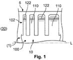
すなわち、本発明は、コンタクト区間10におけるそれぞれのコンタクトばね110の位置に起因して変更可能なばね設計を有するコンタクトばね110を有する、コンタクト区間10を提供する。ここでは、それぞれのコンタクトばね110は、対合コンタクト手段5に機械的に接触する目的でも設けられる。より小さい幅を有するコンタクトばね(110)は、より大きい幅を有するコンタクトばね(110)よりも高い電気抵抗率Rcsを有するので、コンタクト区間10におけるコンタクトばね110の断面は、独創的な方法で適合される。本発明によれば、接続区間30の比較的近くに位置付けられる、より小さい幅(すなわちより小さい断面)を有するコンタクトばね110が設けられ、また、接続区間30から比較的遠くに離れて位置付けられる、より大きい幅(すなわちより大きい断面)を有するコンタクトばね110が設けられる(図1を参照)。
That is, the present invention provides a
さらに、対合コンタクト手段5に対するコンタクトばね110の接触法線力は、そのような(点のまたは面の)接続部を通ってどのくらいの量の電流が流れることができるかに対して、大きな影響を及ぼし得る。したがって、コンタクトばね110の長さも適合させることができる。ここでは、より小さい幅を有するコンタクトばね110は、より大きい幅を有するコンタクトばね110よりも低い接触法線力を有する。したがって、それぞれのコンタクトばね110に関して一定の法線力を得るために、より大きい幅を有するコンタクトばね110の長さを、大きくすることができる。本発明によれば、接続区間30の比較的近くに位置付けられる、より短い長さを有するコンタクトばね110が設けられることができ、また、接続区間30から比較的遠くに離れて位置付けられる、より長い長さを有するコンタクトばね110が設けられる(図2も参照)。この場合、より短い長さを有するコンタクトばね110はまた、より小さい幅を有し、一方、より長い長さを有するコンタクトばね110はまた、より大きい幅を有する。
Furthermore, the contact normal force of the
コンタクトばね110の変更可能な設計により、コンタクト区間10において異なる長さおよび幅を有する複数のコンタクトばね110が提供される。コンタクトばね110が接続区間30に近いほど、そのコンタクトばね110は特に、より小さくかつ好ましくはより短くなる。コンタクトばね110が接続区間30から遠く離れているほど、そのコンタクトばね110は特に、より幅広でかつ好ましくはより大きくなる。ここでは、各コンタクトばね110は、電気経路に沿ったバルク抵抗率Rb(図5を参照)が、それぞれのコンタクトばね110の抵抗率Rcsによって、コンタクト区間10またはコンタクト手段1の一部もしくは全体にわたって等しくされるような方法で、特に設計される。コンタクトばね110を、コンタクト手段1の電気コンタクト本体100に直接プレス加工して設けることができる。このコンタクト手段1は、同様に圧延金属条片から製作することのできる対合コンタクト手段5の電気コンタクト区間によって、電気的におよび機械的に接触可能である。
The changeable design of the
一般に、コンタクトばね110の形状は任意である。たとえば、コンタクトばね110は、i字形状、V字形状、またはU字形状(埋めてあるもの)とすることができる。一般に、舌部、腕部、薄板、鼻部、条片、棒(bar)、または杆体(rod)の形状が好ましい。ここでは、コンタクトばね110の水平方向の、垂直方向の、および/もしくは高さ(elevation)方向の突出、または、コンタクトばね110の水平方向の、垂直方向の、および/もしくは高さ(elevation)方向の突出の分布は、任意である。すなわち、それぞれのコンタクトばね110の断面の分布すなわち外形を、上述の機能に従って選択することができる。それぞれ、コンタクト区間10において接続区間30に対する位置が同様である、すなわちコンタクト手段1またはそのコンタクト本体100において同一のバルク抵抗率Rbを有する、2つの(図3)またはそれを超える(図4、4つ)コンタクトばね110が、幾何学的に同一の様式で、すなわち同一のコンタクトばね抵抗率Rcsを有して、好ましくは構築される。
In general, the shape of the
本発明によれば、それぞれのコンタクトばね110の電気抵抗率Rcsは、コンタクトばね110の電気的および機械的接触領域122、たとえばコンタクト突起122、コンタクト突出部122、コンタクト波形部122、等と、そのコンタクト本体100への接続部または接合部との間で、特に調整される。コンタクト領域122とコンタクトばね110のコンタクト本体100への接続部との間の、材料の量およびその幾何学形状は、残りのコンタクト本体100の脇の/オフ側の、コンタクトばね110自体;すなわちコンタクトばね110の材料に関する、電気抵抗率Rcsを決定する。この電気抵抗率Rcsは、コンタクト本体100および/または接続区間30の、1つの対応する大容積部分n=1から6の1つの電気抵抗率Rb,n、または、複数の対応する大容積部分n=1から6の複数の電気抵抗率Rb,n、…を考慮に入れて調整される(図5を参照)。
In accordance with the present invention, the electrical resistivity R cs of each
本発明によれば、コンタクトばね110に関して、それらの位置(対応する1つの大容積部分n=1から6または複数の大容積部分n=1から6)に起因して決定された電気抵抗率Rcsにより、コンタクト領域122とコンタクトばね110のコンタクト本体100への接続部との間の材料の量および幾何学形状、すなわちコンタクトばね110の形態が、逆に決定される。これは、自体の長手方向において、コンタクト本体100に至る1つの側部のところでコンタクト本体100に接続されるコンタクトばね110に関する。コンタクトばね110がたとえば、コンタクト薄板110として設計される場合、すなわち、これがその長手方向において、コンタクト本体100の2つの側部のところでコンタクト本体100に接続される場合(図示せず)、本発明によれば、これをコンタクト薄板110の両方の分岐部に対して実行しなければならない。
According to the invention, the electrical resistivity R determined for the contact springs 110 due to their position (corresponding one large volume portion n = 1 to 6 or a plurality of large volume portions n = 1 to 6). By cs , the amount and geometry of the material between the
示された本発明の実施形態では、各コンタクトばね110は、コンタクト本体100のただ1つの側部のところに、特にコンタクト手段1と一体の構成でまたはこれとともに1つの材料の個片として設けられる。本発明によれば、コンタクトばね110、好ましくは全てのコンタクトばね110は、コンタクトばね110を通って流れることのできる電流に関して第一に優先されるような経路が存在しないような方法で、コンタクト本体100において構成され設置される。すなわち、それぞれのコンタクトばね110を通りこのコンタクトばね110から離れる電流に関する経路、可能であれば全ての経路は、電流にとって主としてまたは本質的に、等しく「誘引力のある」ものであるべきである。ここでは、たとえばコンタクト手段1の部分的本体100としてのコンタクト本体100を、(開放)ばねコンタクト本体100、コンタクトリテーナ100、コンタクトケージ100、レセプタクル100、等として、さらに構成することができる。
In the embodiment of the invention shown, each
図1は、互いから等しく距離を置かれかつ全てが本質的に同じ長さを有する4つのコンタクトばね110を有する、コンタクト区間10の第1の実施形態を示す。当然ながら、コンタクト区間10において、4つよりも少ないまたは多い、等しく距離を置かれたコンタクトばね110を適用することも可能である。ここでは、コンタクトばね110は、全てコンタクト本体100のただ1つの側部に結着される。このコンタクト本体100は、コンタクトばね110と1つになって、コンタクト手段1のコンタクト区間10を構成する。以下では、コンタクトばね110がコンタクト本体100のただ1つの側部に固定されたそのような構成は、コンタクト本体100のところの/における、またはコンタクト区間10のところの/におけるコンタクトばね110の配置構成102とも称する。
FIG. 1 shows a first embodiment of a
接続区間30(図示しないが、図1から左)までの各コンタクトばね110の様々な距離に起因する電気抵抗率Rbを補償するために、全てのコンタクトばね110の様々な幅が適用される。この場合、コンタクトばね110の長さおよび厚さは等しいままである。すなわち、コンタクトばね110の接触法線力は、コンタクトばね110の長さによって補償されていない。接触法線力の補償はこの場合、コンタクトばね110の幅によって実施され得る。すなわち、コンタクトばね110の接触法線力がより低くなるにつれ、その幅を少し大きく増加させることができるか、または、コンタクトばね110の接触法線力がより高くなるにつれ、その幅を以下で説明するよりも少し小さく増加させることができる。このことは、別法としてまたは追加として、コンタクトばね110同士の間の様々な距離によっても実現可能である。
Different widths of all contact springs 110 are applied to compensate for the electrical resistivity R b due to different distances of each
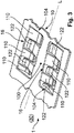
図2は、各々異なる幅を備える4つのコンタクトばね110を同じく有する、コンタクト区間10の本発明の第2の実施形態を表す。ここでは、図1に対する相違点だけを以下で説明する。ここでは、コンタクトばね110は互いから等しく距離を置かれておらず、かつ同じ長さを本質的に有さない。すなわち、接続区間30までの各コンタクトばね110の様々な距離に起因する電気抵抗率Rbの、各コンタクトばね110の様々な幅に起因する補償とは別に、コンタクトばね110の様々な長さおよび/またはその互いの間の様々な距離に起因する、各コンタクトばね110の接触法線力の補償が適用される。
FIG. 2 represents a second embodiment of the invention of the
コンタクトばね110の様々な長さは、コンタクト区間10の中央領域において、コンタクト本体100の面積を図1と比較して大きくすることによって実現可能である。この場合、コンタクトばね110の先端部を、対合コンタクト手段5の縁部と平行で有り得る直線状に配置することができる(図1も同様)。さらに、コンタクト区間10の中央領域を、本質的に矩形とすることができる。この場合、コンタクトばね110の先端部を、直線状にまたは曲線状に配置することができ、これらの直線または曲線は、対合コンタクト手段5(図示せず)の縁部に対して角度を付けることができる。
Various lengths of the
たとえば、好ましくは打ち抜きされるコンタクトばね110に起因してコンタクト区間10の剛性を過剰に弱めないために、コンタクトばね110を、交互に対向する様式で配置することができる。この場合、コンタクトばね110は、コンタクト区間10の開口した内側フレーム16内に好ましくは配置される。このことはたとえば、コンタクト手段1の長手方向L(図4における点線で描かれた差し込み方向Pでもある)において、1つのコンタクトばね110が、右寄りに(または左寄りにそれぞれ)位置付けられるコンタクト区間10の側部に接続されることを意味する。一方、長手方向Lにおいて好ましくは直接隣接して位置付けられるコンタクトばね110がその場合、左寄りに(または右寄りにそれぞれ)位置付けられるコンタクト区間10の側部に接続されることを意味する。
For example, the contact springs 110 can be arranged in an alternating manner in order not to excessively weaken the rigidity of the
結果として、コンタクト区間10の一部分において互いに対向して配置されたコンタクトばね110は、互いに組み合うかまたは噛み合う。ここでは、各側部はそれぞれのコンタクトばね110とともに、コンタクトばね110の配置構成102を構成し、この場合、これらの2つの配置構成102は、互いに噛合し、このことによりコンタクトばね110の(2つの配置構成102の)配列104を構成する。特にコンタクトばね110が傾斜した側部を有する場合、単一の配列104中の2つの配置構成102のうちの一方が、この配列104の直接対向しかつ隣接する配置構成102よりも1つ多いコンタクトばね110を備えることは、有利であり得る。たとえば2つの配列104、104がコンタクト区間10の層12、14(以下を参照)中に設けられる場合、2つの配列104の2つの内側側部が、2つの配列104の2つの外側側部よりも1つ少ないコンタクトばね110を備えることが好ましい。当然ながら、このことは逆の様式で実行され得る。
As a result, the contact springs 110 disposed opposite to each other in a part of the
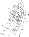
コンタクト区間10における、コンタクトばね110の(たとえば4つの配置構成102、102;102、102の)2つの配列104、104の独創的な構成を、本発明の第3の実施形態を描写する図3に示す。コンタクト区間10の一部分においては、より小さい幅を有するコンタクトばね110は、接続区間30(図3には図示しないが、括弧に入れた参照符号により示す)に近接して設けられる。より大きい幅を有するコンタクトばね110は、接続区間30からより遠く離れて配置される。コンタクトばね110および/またはそれらのコンタクト領域122は、接続区間30からの距離が大きくなるのに伴い、より幅広になる。このことは、コンタクトばね110の長さにも同様に当てはめることができる。
FIG. 3 depicts an inventive configuration of two
より小さい幅を有するコンタクトばね(110)は、より高い電気抵抗率(Rcs)を有するので、本発明によるコンタクトばね110の幅は、電流がコンタクト本体10および/またはコンタクト手段1を通って流れることを考慮に入れたときに、それぞれのコンタクトばね110(添え字cs)およびその対応する1つの大容積部分(添え字b)または複数の大容積部分(添え字b)の電気抵抗R=Rcs+Rbが、全てのコンタクトばね110に関して本質的に等しくなるような方法で、定められるかまたは選ばれる(以下および図5を参照)。さらに、より大きい幅を有するコンタクトばね(110)は、より高い接触法線力を有するので、それらの長さを、対合コンタクト手段5上に押圧され得る本質的に全てのコンタクトばね110が一定の接触法線力を生成するように、大きくすることができる。
Since the contact spring (110) having a smaller width has a higher electrical resistivity (R cs ), the width of the
一方で、コンタクトばね110の幅は、コンタクト本体100の接続区間30の近くに始まりコンタクト手段1の長手方向Lに沿って、連続的に大きくなる。すなわち、問題となっているコンタクトばね110が接続区間30からより遠く離れるほど、その構成はより幅広になる。他方で、コンタクトばね110の長さは好ましくは、コンタクト本体100の接続区間30の近くに始まりコンタクト手段1の長手方向Lに沿って、連続的に大きくなる。すなわち、問題となっているコンタクトばね110が接続区間30からより遠く離れるほど、その構成はより長くなる。このことは、それぞれのコンタクト領域122とコンタクト本体100へのそれぞれの接続部または接合部との間のコンタクトばね110の幅および/または長さに対して、同様に当てはめることができる。
On the other hand, the width of the
独創的なコンタクト本体100、独創的なコンタクト区間10、および/または圧着コンタクト手段1として好ましくは構成される独創的なコンタクト手段1の第4の実施形態を、図4および図5に描写する。コンタクト本体100を、コンタクト区間10を構成する上側の層12および下側の層14を備えるコンタクトリテーナ100として構成することができる。コンタクト本体100の中に、対合コンタクト手段5を、90°および/または270°の方向において(両方の差し込み方向P、接続方向P、または配向Pを、図4において実線部を有する矢印によって示す)、好ましくは差し込むことができる。さらに、コンタクト本体100を、対合コンタクト手段5を、0°の方向において(この差し込み方向Pを、図4において点線部を有する矢印によって示す)差し込みできるような方法で、構成することができる。異なる差し込み方向P(図示せず)を可能にし得る他のコンタクト本体100が適用可能である。
A fourth embodiment of the inventive contact means 1, preferably configured as the
コンタクトリテーナ100の各層12、14は、コンタクトばね110の少なくとも1つの配置構成102(図示せず、上記、図1を参照)を備える。各層12、14は、コンタクトばね110の少なくとも1つの配列104(同じく図示せず、同じく上記を参照)を好ましくは備える。各層12、14は、並べて配置される、コンタクトばね110の2つの配列104、104(図4、再度上記、図3を参照)を特に備える。原則的には、各配置構成102または配列104におけるコンタクトばね110の量は、任意である。図4および図5は現況では、各配列104において5つのコンタクトばね110を示す。この場合、各配列104は2つの配置構成102から構成される。またこの場合、1つの配置構成102は2つ(それぞれの内側フレーム16、16の内側長手側部)、およびこの配列104の相補の関係にある配置構成102は3つ(それぞれの内側フレーム16、16の外側長手側部)の、コンタクトばね110を備える。
Each layer 12, 14 of the
コンタクト区間10において同様の位置を有する、配置構成102、102;102、102または配列104、104のこれらのコンタクトばね110は、本質的に同じ幾何学形状、すなわち同じ幅、同じ長さ、および同じ厚さを有する。このことは現況では、コンタクト区間10において本質的に同一の長手方向の位置を有するコンタクトばね110に当てはまる。図4によれば、コンタクト区間10の20個のコンタクトばね110のうちの4つのコンタクトばね110が、コンタクト区間10において同様の位置をそれぞれ有する。これらの位置は、本質的に同一のバルク抵抗率Rbによって特徴付けられる。すなわち、これらの4つのコンタクトばね110の対応する1つの大容積部分または複数の大容積部分の長さは、好ましくは本質的に同一であり、また本質的に同一の幾何学形状を好ましくは備える。
These contact springs 110 in
図5は、それぞれのコンタクトばね110、m(m=位置111から115)の電気抵抗率Rcs,m、および対応する1つの大容積部分nまたは複数の大容積部分n(n=位置1から6)の電気抵抗率Rb,mを例示する。コンタクト区間10を通って接続区間30の中に流れることのできる電流の可能な各通路に関する、独創的な同等の抵抗Rは、以下の通りである。
R=/≒Rcs,111+Rb,6+Rb,5+Rb,4+Rb,1=/≒
=/≒Rcs,112+Rb,3+Rb,2+Rb,1=/≒
=/≒Rcs,113+Rb,5+Rb,4+Rb,1=/≒
=/≒Rcs,114+Rb,2+Rb,1=/≒
=/≒Rcs,115+Rb,4+Rb,1=/≒R
FIG. 5 shows the electrical resistivity R cs, m of each
R = / ≈Rcs, 111 + Rb, 6 + Rb, 5 + Rb, 4 + Rb, 1 = / ≈
= / ≈Rcs, 112 + Rb, 3 + Rb, 2 + Rb, 1 = / ≈
= / ≈Rcs, 113 + Rb, 5 + Rb, 4 + Rb, 1 = / ≈
= / ≈Rcs, 114 + Rb, 2 + Rb, 1 = / ≈
= / ≈R cs, 115 + R b, 4 + R b, 1 = / ≈R
等式のこの系に従って、かつ各コンタクトばね110;111、112、113、114、115に関する所与のバルク抵抗Rb,n;Rb,1、Rb,2、Rb,3、Rb,4、Rb,5、Rb,6を用いて、この独創的な方法で要求される電気抵抗率Rcs,m;Rcs,111、Rcs,112、Rcs,113、Rcs,114、Rcs,115を計算することができる。さらに、それぞれのコンタクトばね110;111、112、113、114、115の幾何学形状を、計算し、計算された電気抵抗率Rcs,m;Rcs,111、Rcs,112、Rcs,113、Rcs,114、Rcs,115から選択することができる。
According to this system of equations, and for each
コンタクトばね110、mの電気抵抗は、以下の通り与えられる。
Rcs,m=(ρ・lcs,m)/Acs,m
ρはコンタクト手段1の材料の比電気抵抗、lcs,mはそれぞれのコンタクトばね110;111、112、113、114、115の(媒体)長さ、Acs,mはそれぞれのコンタクトばね110;111、112、113、114、115の(媒体)断面積である。
The electrical resistance of the contact springs 110, m is given as follows.
R cs, m = (ρ · l cs, m ) / A cs, m
ρ is the specific electrical resistance of the material of the contact means 1, l cs, m is the
コンタクト手段1の材料厚さは、少なくとも部分的に等しいので、それぞれのコンタクトばね110;111、112、113、114、115の幾何学形状の適合は、それぞれのコンタクトばね110;111、112、113、114、115の幅の適合によって達成することができる。さらに、コンタクトばね110、mの電気抵抗Rcs,mに関するこの式により、大容積部分n(n=位置1から6)に関する電気抵抗Rb,n;Rb,1、Rb,2、Rb,3、Rb,4、Rb,5、Rb,6を推定または計算することもできる。
Since the material thickness of the contact means 1 is at least partly equal, the conformity of the geometry of the
1 たとえば自動車産業用の、特に銅製またはアルミニウム製ケーブルのための、金属/金属合金から製作されたいくつかの部品としての、1つの個片としての、1つの材料の個片としての、または一体型の形態としての閉じた構成を有する、(直線状の、好ましくは90°の角度の付いた、および/または湾曲した)(電気/電子)コンタクト手段;さらにはたとえば、端子、圧着コンタクト手段、電気/超音波溶接コンタクト手段、雌型、ソケット型、プラグ型コンタクト手段、プラグインスリーブ、カプリング、レセプタクル、等
2 電気ケーブルの導電体(図示せず);さらにたとえば、接続区間30(図示しないが図4および図5に示唆する)上に/接続区間30のところに、機械的に締め付けされた、圧着された、ろう付けされた、はんだ付けされた、圧縮成形された、溶接された、等である;電線(リッツ線)、リード線、撚り線、可撓線、コード、等
5 たとえば自動車産業用の、特に銅製またはアルミニウム製ケーブルのための、金属/金属合金で製作されたいくつかの部品としての、1つの個片としての、1つの材料の個片としての、または一体型の形態としての閉じた構成を有する、(電気/電子)対合コンタクト手段;さらにはたとえば、圧着型、タブ型、ピン型コンタクト手段、ファストオンタブ、フラットプラグ、等
10 対合コンタクト手段5のための(電気的/電子的および機械的)コンタクト区間;例示のコンタクト手段1に関して
12 上側の層、側面
14 下側の層、側面
16 開口した内側フレーム
20 コンタクト区間10と接続区間30との間の(電気的/電子的および機械的)移行区間;例示のコンタクト手段1に関して
30 導電体2のための(電気的/電子的および機械的)接続区間;さらにたとえば、導体圧着区間、等;例示のコンタクト手段1に関して
100 (電気的/電子的および機械的)コンタクト本体、コンタクト手段1の部分的本体;さらにたとえば、(開放)ばねコンタクト本体、コンタクトリテーナ、コンタクトケージ、レセプタクル、等
102 コンタクトばね110の配置構成
104 コンタクトばね110の配列、好ましくはコンタクトばね110の2つの互いに噛合する配置構成102
110 (電気的/電子的および機械的)コンタクトばね;さらにたとえば、コンタクト(ばね)舌部、腕部、薄板、鼻部、条片、棒、杆体、等(位置111から115も同様)
122 (電気的/電子的および機械的)コンタクト領域;さらにたとえば、コンタクト突起、コンタクト突出部、コンタクト波形部、等
L コンタクト手段1、およびそのコンタクト区間10、接続区間、固定区間、等の長手方向
P コンタクト手段1への/その中への対合コンタクト手段5の差し込み方向、好ましくは90°および/または0°、該当する場合270°;さらにたとえば接続方向、配向
R 電気抵抗
Rb,n それぞれの大容積部分の電気抵抗率(n=図5における位置1から6)
Rcs,m それぞれのコンタクトばねの電気抵抗率(m=図5における位置111から115)
図示せず
・接続区間30と固定区間との間の(機械的)移行区間(任意選択);例示のコンタクト手段1に関して
・電気絶縁部のための(また、当てはまる場合は、電気ケーブルの(電気絶縁部を介した)導体のための)(機械的)固定区間(任意選択);さらにたとえば、絶縁圧着区間;例示のコンタクト手段1に関して
・導電体2を有する電気ケーブル;さらにたとえば、電線、導電体、等
・電気ケーブル組立体;さらにたとえば、事前組立されたケーブル、既製品のケーブル、電気配線ハーネス、等
1 as several pieces made from metal / metal alloys, for example for the automotive industry, in particular for copper or aluminum cables, as one piece, as one piece of material, or as one piece (Electrical / Electronic) contact means (straight, preferably 90 ° angled and / or curved) having a closed configuration in the form of a body; and for example terminals, crimp contact means, Electrical / ultrasonic welding contact means, female type, socket type, plug type contact means, plug-in sleeve, coupling, receptacle, etc. 2 Conductor of electric cable (not shown); Further, for example, connection section 30 (not shown) (Implyed in FIG. 4 and FIG. 5) above / in the
110 (electrical / electronic and mechanical) contact springs; for example, contact (spring) tongues, arms, thin plates, noses, strips, rods, rods, etc. (same for
122 (electrical / electronic and mechanical) contact region; further, for example, contact protrusion, contact protrusion, contact corrugation, etc. L contact means 1, and its longitudinal direction such as
Electric resistivity of each contact spring of R cs, m (m =
(Not shown) (mechanical) transition section (optional) between the
Claims (14)
電気対合コンタクト手段(5)によって電気的に接触可能な電気コンタクト区間(10)を有し、前記電気コンタクト区間(10)が、前記対合コンタクト手段(5)に電気的に接触するための複数または多数のコンタクトばね(110)を備える、電気コンタクト手段において、
前記コンタクト区間(10)が、前記コンタクト手段(1)を通してバランスのとれた電流分布を得るために、異なる幾何学的形状を有する、少なくとも2つの、好ましくは少なくとも3つ、4つ、またはこれより多くのコンタクトばね(110)を備えることを特徴とする
電気コンタクト手段。 Electrical contact means for a power connection for a copper or aluminum cable for the automotive industry, preferably female contact means (1),
An electrical contact section (10) that is electrically contactable by an electrical mating contact means (5), wherein the electrical contact section (10) is in electrical contact with the mating contact means (5) In an electrical contact means comprising a plurality or multiple contact springs (110),
The contact section (10) has at least two, preferably at least three, four, or more, having different geometric shapes in order to obtain a balanced current distribution through the contact means (1) Electrical contact means comprising a number of contact springs (110).
電気対合コンタクト手段(5)によって電気的に接触可能な電気コンタクト区間(10)を有し、前記電気コンタクト区間(10)が、前記対合コンタクト手段(5)に電気的に接触するための多数のコンタクトばね(110)を備える、電気コンタクト手段において、
前記多数のコンタクトばね(110)のうちの少なくとも複数を通してバランスのとれた電流分布を得るために、この複数のコンタクトばね(110)の各々の電気抵抗率(R)が、これらのコンタクトばね(110)および前記それぞれのコンタクトばね(110)の脇の前記コンタクト手段(1)を通る抵抗経路が主としてまたは本質的に等しくなるような方法で適合されることを特徴とする電気コンタクト手段。 Electrical contact means for a power connection for a copper or aluminum cable for the automotive industry, preferably female contact means (1),
An electrical contact section (10) that is electrically contactable by an electrical mating contact means (5), wherein the electrical contact section (10) is in electrical contact with the mating contact means (5) In electrical contact means comprising a number of contact springs (110),
In order to obtain a balanced current distribution through at least a plurality of the plurality of contact springs (110), the electrical resistivity (R) of each of the plurality of contact springs (110) is determined by the contact springs (110). And an electrical contact means adapted in such a way that the resistance path through the contact means (1) beside each contact spring (110) is mainly or essentially equal.
前記それぞれのコンタクトばね(110;111から115)の前記それぞれの電気抵抗率(Rcs)と、
1つの対応する大容積部分(n=1から6)の電気抵抗率(Rb,n)または複数の前記対応する大容積部分(n=1から6)の電気抵抗率(Rb,n、…)と、の合計が、
前記複数のコンタクトばね(110;111から115)を通る前記電流の各経路に関して好ましくは本質的に決定されることを特徴とする、請求項1または2に記載の電気コンタクト手段。 The design of the contact section (10) is such that the sum of the electrical resistivity (R cs , R b ) of the current path through the plurality of contact springs (110; 111 to 115) and the contact section (10) Structured in such a way as to be mainly or essentially equal between,
The respective electrical resistivity (R cs ) of the respective contact springs (110; 111 to 115);
Electrical resistivity of the one corresponding large volume portion (n = 1 from 6) (R b, n) or more of the electrical resistivity of the corresponding large volume portion (n = 1 from 6) (R b, n, …) And the sum of
Electrical contact means according to claim 1 or 2, characterized in that it is preferably essentially determined for each path of the current through the plurality of contact springs (110; 111 to 115).
これらのコンタクトばね(110;111から115)の少なくとも1つの寸法、好ましくはこれらのコンタクトばね(110;111から115)の幅および/または長さが、前記コンタクト手段(1)におけるこれらのコンタクトばね(110;111から115)の位置に関して適合される、ならびに/あるいは、これらのコンタクトばね(110;111から115)の少なくとも1つの寸法、好ましくはこれらのコンタクトばね(110;111から115)の前記幅および/または前記長さが、問題となっているその他のコンタクトばね(110;111から115)の寸法に関して適合されることを特徴とする、請求項1から3のいずれか一項に記載の電気コンタクト手段。 A generally or essentially equal resistance path (R cs, 111 + R b ) through these contact springs (110; 111 to 115) and the contact means (1) beside each of the contact springs (110; 111 to 115). , 6 + Rb, 5 + Rb, 4 + Rb, 1 = / ≈Rcs, 112 + Rb, 3 + Rb, 2 + Rb, 1 = / ≈Rcs, 113 + Rb, 5 + Rb, 4 + Rb 1 = / ≈R cs, 114 + R b, 2 + R b, 1 = / ≈R cs, 115 + R b, 4 + R b, 1 ) and / or these contact springs (110; 111 to 115) to ensure a roughly or essentially equal proportion of current that can flow through
At least one dimension of these contact springs (110; 111 to 115), preferably the width and / or length of these contact springs (110; 111 to 115) is determined by these contact springs in said contact means (1). Adapted for the position of (110; 111 to 115) and / or said at least one dimension of these contact springs (110; 111 to 115), preferably said of said contact springs (110; 111 to 115) 4. The width and / or the length are adapted with respect to the dimensions of the other contact springs in question (110; 111 to 115). Electrical contact means.
前記複数のコンタクトばね(110;111から115)が、特にそれらの前記コンタクト区間(10)へのそれぞれの接続部とそれらのそれぞれの電気コンタクト領域(122)との間で、互いの間で異なる長さを備えることを特徴とする、請求項1から4のいずれか一項に記載の電気コンタクト手段。 The plurality of contact springs (110; 111 to 115) have different widths between each other and / or
The plurality of contact springs (110; 111 to 115) differ between each other, especially between their respective connections to the contact section (10) and their respective electrical contact regions (122). Electrical contact means according to any one of claims 1 to 4, characterized in that it comprises a length.
より小さい幅を有する前記コンタクトばね(110;113〜115)が、より大きい幅を有する前記コンタクトばね(110;111〜113)よりも前記コンタクト手段(1)の移行区間(20)および/または接続区間(30)の近くに配置されることを特徴とする、請求項1から5のいずれか一項に記載の電気コンタクト手段。 The contact section (10) comprises at least one contact spring (110; 113 to 115) having a smaller width than another contact spring (110; 111 to 113);
The contact section (20) and / or the connection of the contact means (1) is smaller than the contact spring (110; 113-115) having a smaller width than the contact spring (110; 111-113) having a larger width. Electrical contact means according to any one of the preceding claims, characterized in that it is arranged in the vicinity of the section (30).
より短い長さを有する前記コンタクトばね(110;113〜115)が、より長い長さを有する前記コンタクトばね(110;111〜113)よりも前記移行区間(20)および/または前記接続区間(30)の近くに好ましくは配置され、
より短い長さを有する前記コンタクトばね(110;113〜115)が、より長い長さを有する前記コンタクトばね(110;111〜113)よりも小さい幅を好ましくは有し、そしてより長い長さを有する前記コンタクトばね(110;111〜113)が、より短い長さを有する前記コンタクトばね(110;113〜115)よりも大きい幅を有することを特徴とする、請求項1から6のいずれか一項に記載の電気コンタクト手段。 The contact section (10) comprises at least one contact spring (110; 113-115) having a shorter length than another contact spring (110; 111-113);
The contact spring (110; 113-115) having a shorter length is more suitable for the transition section (20) and / or the connection section (30) than the contact spring (110; 111-113) having a longer length. ) Is preferably located near
The contact spring (110; 113-115) having a shorter length preferably has a smaller width than the contact spring (110; 111-113) having a longer length, and has a longer length. The contact spring (110; 111-113) having a greater width than the contact spring (110; 113-115) having a shorter length. The electrical contact means according to Item.
前記配置構成(102)において、前記コンタクトばね(110)の前記長さおよび/または前記幅が、前記コンタクト手段(1)の前記接続区間(30)に向かう方向に減少することを特徴とする、請求項1から7のいずれか一項に記載の電気コンタクト手段。 The contact section (10) comprises an arrangement (102) of contact springs (110) in which the contact springs (110) are arranged continuously;
In the arrangement (102), the length and / or the width of the contact spring (110) decreases in a direction toward the connection section (30) of the contact means (1), The electrical contact means according to any one of claims 1 to 7.
前記配列(104)において、前記コンタクトばね(110)の前記長さおよび/または前記幅が、前記コンタクト手段(1)の前記接続区間(30)に向かう方向に減少することを特徴とする、請求項1から8のいずれか一項に記載の電気コンタクト手段。 Said contact section (10) comprises an arrangement (104) of contact springs (110), said arrangement (104) comprising two interdigitated arrangements (102) of contact springs (110);
In the arrangement (104), the length and / or the width of the contact spring (110) decreases in a direction towards the connection section (30) of the contact means (1). Item 9. The electrical contact means according to any one of Items 1 to 8.
・前記コンタクト本体(100)が、自体の中にまたは自体を通して前記対合コンタクト手段(5)を差し込むことのできる、1つ、2つ、または3つの側面が開いたコンタクトリテーナ(100)またはコンタクトケージ(100)として構成されること;または
・前記コンタクト本体(100)が、前記対合コンタクト手段(5)が前記コンタクト手段(1)の接続面からのみアクセス可能なレセプタクル(100)として構成されること
を特徴とする、請求項1から9のいずれか一項に記載の電気コンタクト手段。 The contact body (100) of the contact section (10) is configured as an open spring contact body (100) into which the mating contact means (5) can be inserted in or through itself. about;
One, two or three side open contact retainers (100) or contacts into which the contact body (100) can insert the mating contact means (5) into or through itself Configured as a cage (100); or the contact body (100) is configured as a receptacle (100) in which the mating contact means (5) is accessible only from the connecting surface of the contact means (1). Electrical contact means according to any one of the preceding claims, characterized in that
コンタクトばね(110)の好ましくは4つの配置構成(102)または好ましくは4つの配列(104)が、前記コンタクト本体(100)の2つの対向する層(12、14)内に収容され、1つの配置構成(102)または1つの配列(104)が、その対向する配置構成(102)または配列(104)と好ましくは面一であることを特徴とする、請求項1から10のいずれか一項に記載の電気コンタクト手段。 At least two arrangements (102) or at least two arrays of contact springs (100), wherein the contact bodies (100) are preferably arranged in opposing layers (12, 14) of the contact bodies (100). (104)
Preferably four arrangements (102) or preferably four arrays (104) of contact springs (110) are housed in two opposing layers (12, 14) of the contact body (100), 11. Arrangement (102) or one arrangement (104) is preferably flush with its opposite arrangement (102) or arrangement (104). Electrical contact means according to.
・コンタクト手段(1)が、圧着、電気、または超音波溶接コンタクト手段(1)として構成されること;
・コンタクトばね(110)が、前記コンタクトばねの1つの長手側部上でまたは2つの長手側部上で前記コンタクト本体(100)に接続されること;
・コンタクトばね(110)が、コンタクト薄板(110)として構成されること;
・コンタクトばね(110)の配置構成(102)が、少なくとも2つのコンタクトばね(110)を備えること;および/あるいは
・コンタクトばね(110)の配列(104)が、少なくとも3つのコンタクトばね(110)を備えること
を特徴とする、請求項1から12のいずれか一項に記載の電気コンタクト手段。 The contact means (1) has a closed configuration, which may be as several parts, as one piece, as one piece of material, or as a unitary form ;
The contact means (1) is configured as a crimp, electrical or ultrasonic welding contact means (1);
A contact spring (110) is connected to the contact body (100) on one longitudinal side of the contact spring or on two longitudinal sides;
The contact spring (110) is configured as a contact lamina (110);
The arrangement (102) of contact springs (110) comprises at least two contact springs (110); and / or the arrangement (104) of contact springs (110) comprises at least three contact springs (110). The electrical contact means according to claim 1, comprising:
請求項1から13のいずれか一項に記載の電気コンタクト手段(1)、好ましくは雌型コンタクト手段(1)を備えることを特徴とする、電気ケーブル組立体。 An electrical cable assembly for a power connection, preferably comprising female contact means (1) for copper or aluminum cables for the automotive industry,
Electrical cable assembly (1) according to any one of the preceding claims, preferably a female contact means (1).
Applications Claiming Priority (2)
| Application Number | Priority Date | Filing Date | Title |
|---|---|---|---|
| EP15153319.7A EP3051635B1 (en) | 2015-01-30 | 2015-01-30 | Electric contact means and electrical cable assembly for the automotive industry |
| EP15153319.7 | 2015-01-30 |
Publications (2)
| Publication Number | Publication Date |
|---|---|
| JP2016143665A true JP2016143665A (en) | 2016-08-08 |
| JP6774757B2 JP6774757B2 (en) | 2020-10-28 |
Family
ID=52444175
Family Applications (1)
| Application Number | Title | Priority Date | Filing Date |
|---|---|---|---|
| JP2015249597A Active JP6774757B2 (en) | 2015-01-30 | 2015-12-22 | Electrical contact means and electrical cable assemblies for the automotive industry |
Country Status (4)
| Country | Link |
|---|---|
| US (1) | US9905950B2 (en) |
| EP (1) | EP3051635B1 (en) |
| JP (1) | JP6774757B2 (en) |
| CN (1) | CN105846200B (en) |
Cited By (2)
| Publication number | Priority date | Publication date | Assignee | Title |
|---|---|---|---|---|
| JP2022182971A (en) * | 2021-05-26 | 2022-12-08 | 宣城立訊精密工業有限公司 | Electrical connection assembly and electrical connector |
| JP2022182972A (en) * | 2021-05-26 | 2022-12-08 | 宣城立訊精密工業有限公司 | Electrical connection assembly and electrical connector |
Families Citing this family (14)
| Publication number | Priority date | Publication date | Assignee | Title |
|---|---|---|---|---|
| US9905953B1 (en) | 2016-09-30 | 2018-02-27 | Slobodan Pavlovic | High power spring-actuated electrical connector |
| DE102016221351A1 (en) * | 2016-10-28 | 2018-05-03 | Te Connectivity Germany Gmbh | Flat contact socket with extension arm |
| DE102016124963A1 (en) * | 2016-12-20 | 2018-06-21 | Te Connectivity Germany Gmbh | Power transport device, in particular electrical or electromechanical busbar |
| JP6588943B2 (en) * | 2017-06-20 | 2019-10-09 | 矢崎総業株式会社 | Terminal connection structure |
| DE102017220778B4 (en) * | 2017-11-21 | 2019-06-13 | Robert Bosch Gmbh | contact element |
| JP6989715B2 (en) | 2018-02-26 | 2022-01-05 | ロイヤル プレシジョン プロダクツ,エルエルシー | Spring-loaded electrical connectors for high power applications |
| WO2019237009A1 (en) | 2018-06-07 | 2019-12-12 | Royal Precision Products, Llc | Electrical connector system with internal spring component |
| US10389055B1 (en) * | 2018-06-20 | 2019-08-20 | Delphia Technologies, Llc | Electrical connector assembly |
| EP3783744A1 (en) * | 2019-08-23 | 2021-02-24 | Yazaki Europe Ltd. | Electric connection arrangement |
| US11721942B2 (en) | 2019-09-09 | 2023-08-08 | Eaton Intelligent Power Limited | Connector system for a component in a power management system in a motor vehicle |
| CN114787815A (en) | 2019-09-09 | 2022-07-22 | 伊顿智能动力有限公司 | Connector recording system with readable and recordable indicia |
| US11605914B2 (en) | 2020-05-05 | 2023-03-14 | Te Connectivity Solutions Gmbh | Electrical contact with multiple contact points having equivalent normal force |
| CN113612050B (en) * | 2020-05-05 | 2023-01-10 | 泰连服务有限公司 | Electrical contact having multiple contact points of equal normal force |
| DE112021003303T5 (en) | 2020-07-29 | 2023-05-25 | Eaton Intelligent Power Limited | ELECTRICAL CONNECTION SYSTEM WITH CYLINDRICAL CLAMP BODY |
Citations (4)
| Publication number | Priority date | Publication date | Assignee | Title |
|---|---|---|---|---|
| JP2011042860A (en) * | 2009-08-24 | 2011-03-03 | Kobe Steel Ltd | Tin plated copper or copper alloy material for connecting component used for connection with aluminum conductive member |
| KR20130027298A (en) * | 2011-09-07 | 2013-03-15 | 엘에스전선 주식회사 | Power connector and power connecting system |
| JP2014035959A (en) * | 2012-08-09 | 2014-02-24 | Auto Network Gijutsu Kenkyusho:Kk | Multi-contact type female terminal |
| JP2014232576A (en) * | 2013-05-28 | 2014-12-11 | 株式会社オートネットワーク技術研究所 | Multi-contact female terminal |
Family Cites Families (38)
| Publication number | Priority date | Publication date | Assignee | Title |
|---|---|---|---|---|
| US4820169A (en) * | 1986-04-22 | 1989-04-11 | Amp Incorporated | Programmable modular connector assembly |
| US5116237A (en) * | 1988-07-11 | 1992-05-26 | Versatile Engineering Co., Inc. | Printed circuit board edge connector |
| US5269712A (en) * | 1992-11-06 | 1993-12-14 | The Whitaker Corporation | Low-force receptacle contact and method of making same |
| US5582519A (en) * | 1994-12-15 | 1996-12-10 | The Whitaker Corporation | Make-first-break-last ground connections |
| US5564952A (en) * | 1994-12-22 | 1996-10-15 | The Whitaker Corporation | Electrical plug connector with blade receiving slots |
| US5890936A (en) * | 1996-10-15 | 1999-04-06 | Ut Automotive Dearborn, Inc. | Electrical terminal |
| US6062919A (en) * | 1997-08-29 | 2000-05-16 | Thomas & Betts International, Inc. | Electrical connector assembly having high current-carrying capability and low insertion force |
| FR2771834B1 (en) * | 1997-12-03 | 2000-01-21 | Socapex Amphenol | ELECTRICAL CONNECTION DEVICE FOR COOPERATING WITH A MOBILE ELECTRONIC MEDIUM |
| EP1319262B1 (en) * | 2000-09-15 | 2009-02-25 | Alcoa Fujikura Ltd. | Electrical terminal socket assembly for vehicular component |
| JP4443017B2 (en) * | 2000-09-25 | 2010-03-31 | 三菱電線工業株式会社 | Connecting terminal |
| TW476466U (en) * | 2000-09-29 | 2002-02-11 | Hon Hai Prec Ind Co Ltd | Electrical connector |
| US6264509B1 (en) * | 2001-01-10 | 2001-07-24 | Yazaki North America, Inc. | High cycle terminal with protected failsafe contact |
| FR2826786B1 (en) * | 2001-06-29 | 2004-03-05 | Framatome Connectors Int | FEMALE ELECTRIC CONTACT |
| US20030060090A1 (en) * | 2001-09-21 | 2003-03-27 | Allgood Christopher L. | High current automotive electrical connector and terminal |
| JP4213559B2 (en) * | 2002-12-27 | 2009-01-21 | 日本碍子株式会社 | Contact sheet, manufacturing method thereof and socket |
| US7185430B2 (en) * | 2003-11-28 | 2007-03-06 | Ngk Insulators, Ltd. | Method of manufacturing contact sheets |
| DE102004015345A1 (en) * | 2004-03-30 | 2005-10-27 | Kostal Kontakt Systeme Gmbh | Electrical socket contact for high current applications |
| KR100574545B1 (en) * | 2004-06-30 | 2006-04-27 | 엘지이노텍 주식회사 | Contact spring structure for vibration motor |
| JP4098290B2 (en) * | 2004-08-31 | 2008-06-11 | モレックス インコーポレーテッド | FFC connector |
| JP2007173198A (en) * | 2005-11-25 | 2007-07-05 | Hitachi Cable Ltd | Electric contact and female terminal |
| CN201430276Y (en) * | 2009-04-23 | 2010-03-24 | 富士康(昆山)电脑接插件有限公司 | Electric connector assembly |
| US8366497B2 (en) * | 2009-06-17 | 2013-02-05 | Lear Corporation | Power terminal |
| WO2011001821A1 (en) * | 2009-07-03 | 2011-01-06 | 矢崎総業株式会社 | Female terminal |
| JP5381492B2 (en) * | 2009-08-19 | 2014-01-08 | 住友電装株式会社 | Female terminal bracket |
| JP5447971B2 (en) * | 2010-04-08 | 2014-03-19 | 住友電装株式会社 | Terminal bracket connection structure |
| US8403707B2 (en) * | 2010-06-22 | 2013-03-26 | Alltop Electronics (Suzhou) Co., Ltd | Power connector with improved retaining member for being flexibly assembled to power contact |
| DE202010010275U1 (en) * | 2010-07-15 | 2011-12-20 | Weidmüller Interface GmbH & Co. KG | Electrical contact part |
| US8419486B2 (en) * | 2010-12-17 | 2013-04-16 | Tyco Electronics Corporation | Receptacle terminal with a contact spring |
| DE102011076988A1 (en) * | 2011-06-06 | 2012-12-06 | Robert Bosch Gmbh | Direct plug-in element with protected direct contact |
| JP5723694B2 (en) * | 2011-06-21 | 2015-05-27 | 矢崎総業株式会社 | Female terminal |
| JP5723695B2 (en) * | 2011-06-21 | 2015-05-27 | 矢崎総業株式会社 | Female terminal |
| US9112292B2 (en) * | 2012-03-16 | 2015-08-18 | Makita Corporation | Terminal structure |
| US8944831B2 (en) * | 2012-04-13 | 2015-02-03 | Fci Americas Technology Llc | Electrical connector having ribbed ground plate with engagement members |
| CN203242849U (en) * | 2012-04-13 | 2013-10-16 | Fci公司 | Electrical connector, lead wire framework assembly and earth plate |
| US8992270B2 (en) * | 2012-09-26 | 2015-03-31 | Lear Corporation | Electrical terminal |
| CN104103931B (en) * | 2013-04-01 | 2018-02-16 | 泰科电子公司 | Electric connector with the electrical contact with multiple contact beams |
| US9070990B2 (en) * | 2013-05-21 | 2015-06-30 | Tyco Electronics Corporation | Power connector having opposing contact springs |
| WO2015001994A1 (en) * | 2013-07-01 | 2015-01-08 | 住友電気工業株式会社 | Different-pitch flat cable connection structure, pitch-conversion flat cable, and method for manufacturing pitch-conversion flat cable |
-
2015
- 2015-01-30 EP EP15153319.7A patent/EP3051635B1/en active Active
- 2015-12-22 JP JP2015249597A patent/JP6774757B2/en active Active
-
2016
- 2016-01-21 CN CN201610042210.6A patent/CN105846200B/en active Active
- 2016-01-28 US US15/008,939 patent/US9905950B2/en active Active
Patent Citations (4)
| Publication number | Priority date | Publication date | Assignee | Title |
|---|---|---|---|---|
| JP2011042860A (en) * | 2009-08-24 | 2011-03-03 | Kobe Steel Ltd | Tin plated copper or copper alloy material for connecting component used for connection with aluminum conductive member |
| KR20130027298A (en) * | 2011-09-07 | 2013-03-15 | 엘에스전선 주식회사 | Power connector and power connecting system |
| JP2014035959A (en) * | 2012-08-09 | 2014-02-24 | Auto Network Gijutsu Kenkyusho:Kk | Multi-contact type female terminal |
| JP2014232576A (en) * | 2013-05-28 | 2014-12-11 | 株式会社オートネットワーク技術研究所 | Multi-contact female terminal |
Cited By (5)
| Publication number | Priority date | Publication date | Assignee | Title |
|---|---|---|---|---|
| JP2022182971A (en) * | 2021-05-26 | 2022-12-08 | 宣城立訊精密工業有限公司 | Electrical connection assembly and electrical connector |
| JP2022182972A (en) * | 2021-05-26 | 2022-12-08 | 宣城立訊精密工業有限公司 | Electrical connection assembly and electrical connector |
| US11677175B2 (en) | 2021-05-26 | 2023-06-13 | Xuancheng Luxshare Precision Industry Co., Ltd. | Electrical connecting assembly and electrical connector |
| JP7309931B2 (en) | 2021-05-26 | 2023-07-18 | 宣城立訊精密工業有限公司 | Electrical connection assemblies and electrical connectors |
| JP7309932B2 (en) | 2021-05-26 | 2023-07-18 | 宣城立訊精密工業有限公司 | Electrical connection assemblies and electrical connectors |
Also Published As
| Publication number | Publication date |
|---|---|
| EP3051635A1 (en) | 2016-08-03 |
| JP6774757B2 (en) | 2020-10-28 |
| US9905950B2 (en) | 2018-02-27 |
| EP3051635B1 (en) | 2018-01-17 |
| US20160226170A1 (en) | 2016-08-04 |
| CN105846200B (en) | 2020-02-07 |
| CN105846200A (en) | 2016-08-10 |
Similar Documents
| Publication | Publication Date | Title |
|---|---|---|
| JP2016143665A (en) | Electric contact means and electrical cable assembly for automotive industry | |
| EP2483969B1 (en) | One-piece conductive clip for push-in wire connector | |
| US8651890B2 (en) | Electrical connector having spring clip assist contact | |
| CN202772303U (en) | Electrical connector and electrical connector assembly | |
| WO1999021256A2 (en) | Hermaphroditic electrical terminal connection | |
| KR101923712B1 (en) | Electrical connector terminal | |
| US9431721B2 (en) | Contact element | |
| CA2817095C (en) | Deflection containing electrical conductor | |
| WO2014034418A1 (en) | Connection terminal | |
| CN103219620A (en) | Bus bar tap element mounted on comb-type bus bar for lamp, has insulation housing extended from comb teeth adjacent to holding arm into clearance between holding arm and associated contact arm to engage in free space at comb teeth | |
| WO2013108928A1 (en) | Flat circuit body with terminal and manufacturing method thereof | |
| CN107078417B (en) | terminal box | |
| US9515440B2 (en) | Multiport terminal with current bars | |
| WO2018147055A1 (en) | Plate-shaped electric conductive member connection structure and plate-shaped electric conduction path | |
| CN107346844B (en) | Connection terminal and electric connector | |
| US9865372B2 (en) | Deflection containing electrical conductor | |
| US11189950B2 (en) | Plug connector with a conductive rubber element | |
| JP2933929B2 (en) | Electrical connector | |
| CN115498447B (en) | Connecting terminal | |
| CN111344909B (en) | Socket contact | |
| CN211958000U (en) | Structure convenient for connecting terminal and connector | |
| CN208508055U (en) | Elastic slice connection structure for Elecrical connector | |
| US3210721A (en) | Electrical connector | |
| JP2010061840A (en) | Low-profile connector for cable connection | |
| WO2009016243A2 (en) | Electrical contact |
Legal Events
| Date | Code | Title | Description |
|---|---|---|---|
| A621 | Written request for application examination |
Free format text: JAPANESE INTERMEDIATE CODE: A621 Effective date: 20181029 |
|
| A977 | Report on retrieval |
Free format text: JAPANESE INTERMEDIATE CODE: A971007 Effective date: 20191018 |
|
| A131 | Notification of reasons for refusal |
Free format text: JAPANESE INTERMEDIATE CODE: A131 Effective date: 20191119 |
|
| A521 | Request for written amendment filed |
Free format text: JAPANESE INTERMEDIATE CODE: A523 Effective date: 20200207 |
|
| A131 | Notification of reasons for refusal |
Free format text: JAPANESE INTERMEDIATE CODE: A131 Effective date: 20200519 |
|
| A521 | Request for written amendment filed |
Free format text: JAPANESE INTERMEDIATE CODE: A523 Effective date: 20200806 |
|
| TRDD | Decision of grant or rejection written | ||
| A01 | Written decision to grant a patent or to grant a registration (utility model) |
Free format text: JAPANESE INTERMEDIATE CODE: A01 Effective date: 20200908 |
|
| A61 | First payment of annual fees (during grant procedure) |
Free format text: JAPANESE INTERMEDIATE CODE: A61 Effective date: 20201005 |
|
| R150 | Certificate of patent or registration of utility model |
Ref document number: 6774757 Country of ref document: JP Free format text: JAPANESE INTERMEDIATE CODE: R150 |
|
| R250 | Receipt of annual fees |
Free format text: JAPANESE INTERMEDIATE CODE: R250 |