JP2016141017A - Head connection substrate and image formation apparatus having head connection substrate - Google Patents
Head connection substrate and image formation apparatus having head connection substrate Download PDFInfo
- Publication number
- JP2016141017A JP2016141017A JP2015017752A JP2015017752A JP2016141017A JP 2016141017 A JP2016141017 A JP 2016141017A JP 2015017752 A JP2015017752 A JP 2015017752A JP 2015017752 A JP2015017752 A JP 2015017752A JP 2016141017 A JP2016141017 A JP 2016141017A
- Authority
- JP
- Japan
- Prior art keywords
- head
- connector
- head connection
- connection board
- ffc
- Prior art date
- Legal status (The legal status is an assumption and is not a legal conclusion. Google has not performed a legal analysis and makes no representation as to the accuracy of the status listed.)
- Pending
Links
Images
Landscapes
- Ink Jet (AREA)
Abstract
Description
本発明は、ヘッド接続基板及びヘッド接続基板を備えた画像形成装置に関する。 The present invention relates to a head connection substrate and an image forming apparatus including the head connection substrate.
プリンタ等の画像形成装置では、印刷方式として、記録用紙にインクを吐出して印刷を行うインクジェット方式、及び帯電した感光ドラムの表面にレーザ光の照射により電圧変化パターンを発生させてトナーを吸着させ、このトナーを記録用紙に転写して印刷を行うレーザ方式が、主に採用されている。 In an image forming apparatus such as a printer, as a printing method, an ink jet method that performs printing by ejecting ink onto recording paper, and a voltage change pattern is generated on the surface of a charged photosensitive drum by laser light irradiation to attract the toner. A laser method is mainly employed in which printing is performed by transferring the toner onto a recording sheet.
これらの画像形成装置のうち、インクジェット方式を用いた画像形成装置(以下、インクジェットプリンタという)は、インクを吐出するための多数のノズルを備えたインクジェットヘッドを有し、このインクジェットヘッドのノズルから記録媒体にインクを吐出することにより記録媒体上に画像を形成する。 Among these image forming apparatuses, an image forming apparatus using an ink jet method (hereinafter referred to as an ink jet printer) has an ink jet head having a large number of nozzles for ejecting ink, and recording is performed from the nozzles of the ink jet head. An image is formed on the recording medium by ejecting ink onto the medium.
なお、このインクジェットプリンタでは、インクジェットヘッドを、所定の実装エリアであるキャリッジ内部のヘッド接続基板に柔軟性がある配線手段(FPC;フレキシブル配線基板;Flexible Printed Circuits)で実装している。
また、ヘッド接続基板には、インクジェットプリンタの制御部とそれぞれ配線手段であるFFC(フレキシブルフラットケーブル;Flexible Flat Cable)や用紙検出、温度、インク容量検出等の各種センサの信号を転送するハーネスを接続するためのコネクタが配置される。
In this ink jet printer, the ink jet head is mounted by flexible wiring means (FPC: Flexible Printed Circuits) on the head connection substrate inside the carriage, which is a predetermined mounting area.
In addition, the head connection board is connected to the control unit of the ink jet printer and a harness that transfers signals from various sensors such as FFC (Flexible Flat Cable) and paper detection, temperature, and ink capacity detection. A connector is arranged for
ところで、このようなインクジェットプリンタには、キャリッジ内部に2個のインクジェットヘッドを実装させ、印刷速度を向上させたものがある(特許文献1)。
この場合、ヘッド接続基板としては、ヘッド2個の構成にしておけば、ヘッド1個実装と2個実装の両方に使用することができる。しかし、1個のヘッド接続基板にヘッド2個実装に対応させると基板サイズが大きくなり、1個実装のヘッド接続基板に対してコスト面で対応できなくなる。
By the way, there is an ink jet printer in which two ink jet heads are mounted inside a carriage to improve the printing speed (Patent Document 1).
In this case, if the head connection substrate is configured with two heads, it can be used for both mounting one head and two heads. However, if two heads are mounted on one head connection board, the board size becomes large, and it becomes impossible to deal with one head connection board in terms of cost.
また、ヘッド接続基板をヘッド2個用の構成にした場合、ヘッド1個用の構成に対し、2個目のヘッド制御信号とヘッド駆動信号用のコネクタが必要になる。ところが、ヘッド駆動信号は高電圧の信号であるため、ヘッド制御信号と同じFFCで転送すると制御信号にノイズが発生して誤動作の原因になる。また、ヘッド制御信号とヘッド駆動信号を転送するFFCを分けると、FFCコネクタが2個増えることになり、ヘッド接続基板への実装が困難になりコストも増大するという問題がある。 Further, when the head connection substrate is configured for two heads, a second head control signal and head drive signal connector is required for the configuration for one head. However, since the head drive signal is a high voltage signal, if it is transferred by the same FFC as the head control signal, noise is generated in the control signal, causing malfunction. Further, if the FFC for transferring the head control signal and the head drive signal is separated, there are two FFC connectors, which makes it difficult to mount on the head connection board and increases the cost.
本発明は、前記従来の問題に鑑みてなされたものであって、その目的は、1個のヘッドを実装するヘッド接続基板に比して、そのコストの増大を抑えた複数ヘッド実装用のヘッド接続基板を提供することである。 The present invention has been made in view of the above-described conventional problems, and an object of the present invention is to provide a head for mounting a plurality of heads, in which an increase in cost is suppressed as compared with a head connection substrate on which one head is mounted. It is to provide a connection board.
本発明は、複数のヘッドに接続するヘッドコネクタと、ヘッド駆動信号用コネクタ及びヘッド制御信号用コネクタを備え、画像形成装置の所定の実装エリアに配置されるヘッド接続基板であって、前記ヘッド駆動信号用コネクタと前記ヘッド制御信号用コネクタとは別のコネクタとして構成されており、前記各コネクタの少なくとも1つは、当該ヘッド接続基板が前記実装エリアに配置されたとき、1個のヘッドを実装するヘッド接続基板を前記実装エリアに配置するときの当該ヘッド接続基板における対応するコネクタの位置と同じ位置になるように位置決めされたヘッド接続基板である。 The present invention is a head connection board that includes a head connector connected to a plurality of heads, a head drive signal connector, and a head control signal connector, and is disposed in a predetermined mounting area of the image forming apparatus, the head drive The signal connector and the head control signal connector are configured as separate connectors, and at least one of the connectors is mounted with one head when the head connection board is disposed in the mounting area. The head connection board is positioned so as to be in the same position as the corresponding connector on the head connection board when the head connection board is placed in the mounting area.
本発明によれば、1個のヘッドを実装するヘッド接続基板に比してそのコストの増大を抑えた複数ヘッド実装用のヘッド接続基板を提供することができる。 According to the present invention, it is possible to provide a head connection substrate for mounting a plurality of heads, in which an increase in cost is suppressed as compared with a head connection substrate on which one head is mounted.
以下、本発明の実施形態について図面を参照して説明する。
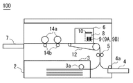
図1は、本発明の実施形態に係るヘッド接続基板10を設置した画像形成装置(ここでは、一例としてインクジェットプリンタ)100の概略図である。
インクジェットプリンタ100は、外部機器(例えば、パーソナルコンピュータ)に接続されている。インクジェットプリンタ100は、外部機器から印刷要求があると、給紙部2にセットされた給紙トレイ(給紙バンク)3又は手差しトレイ4に収納した記録用紙を給紙ローラ3a又は4aにより1枚ずつ分離して上方に搬送する。
Embodiments of the present invention will be described below with reference to the drawings.
FIG. 1 is a schematic view of an image forming apparatus (here, an inkjet printer as an example) 100 provided with a
The
搬送された記録用紙は、レジストセンサの位置で一旦停止され、画像データの出力タイミングに合わせてレジストローラ5により給紙される。
記録用紙は、その後ベルト搬送部12で搬送され、書き込み部6で印刷される。印刷後の記録用紙は、水平搬送ローラ14a及び拍車14bにより搬送され、排紙部7に排紙される。
The conveyed recording sheet is temporarily stopped at the position of the registration sensor, and is fed by the
The recording paper is then transported by the
書き込み部6は、複数の微小なノズルからインク等の記録液を液滴化して吐出するインクジェットヘッド9、及びそのインクジェットヘッド9を実装するキャリッジ8を備えている。インクジェットプリンタ100は、印刷処理時に、キャリッジ8を記録用紙の搬送方向に対して垂直方向に走査し、インクを各色の印刷データに基づいてインクジェットヘッド9により記録用紙上に吐出する。
The
なお、図1に示す例では、インジェットヘッドとして、ブラックの記録液の液滴を吐出するインクジェットヘッドを2個実装している。しかし、本実施形態に係るインクジェットプリンタでは、1個のインクジェットヘッド(9A)を実装する場合と2個のインクジェットヘッド(9A及び9B)を実装する場合の双方の印刷に対応している。
また、キャリッジ8内には、インクジェットヘッド9以外に、インクジェットヘッド9を駆動及び制御する信号等の転送に用いられる各種コネクタが配置されたヘッド接続基板10が設置される。
In the example shown in FIG. 1, two inkjet heads that discharge droplets of black recording liquid are mounted as the jet heads. However, the ink jet printer according to the present embodiment supports both printing when mounting one ink jet head (9A) and mounting two ink jet heads (9A and 9B).
Further, in the carriage 8, in addition to the
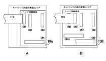
図2は、図1に示すインクジェットプリンタ100のヘッド接続基板10(10A又は10B)の模式図である。
図2に示すヘッド接続基板10において、ここでは、先ず、1個のインクジェットヘッド実装用ヘッド接続基板10Aをキャリッジの所定エリアに配置する場合(図2A)について説明する。その後、2個のインクジェットヘッド実装用ヘッド接続基板10Bをキャリッジの所定エリアに配置する場合(図2B)について説明する。
FIG. 2 is a schematic diagram of the head connection substrate 10 (10A or 10B) of the
In the
1個のインクジェットヘッド実装用ヘッド接続基板10Aには、図2Aに示すように4個のコネクタCN1〜CN4が配置されている。
ここで、CN1は、インクジェットプリンタ100本体の制御部と接続するヘッド駆動信号用FFCを接続するコネクタ(ヘッド駆動信号用FFCコネクタ)である。ヘッド駆動信号用FFCコネクタCN1にはインクジェットプリンタ100本体の制御部からヘッド駆動信号が転送される。
As shown in FIG. 2A, four connectors CN1 to CN4 are arranged on one inkjet head mounting
Here, CN1 is a connector (head drive signal FFC connector) that connects a head drive signal FFC to be connected to the control unit of the main body of the
CN2は、インクジェットプリンタ100本体の制御部と接続するヘッド制御信号用FFCを接続するコネクタ(制御信号用FFCコネクタ)である。
CN3は、キャリッジ8内に実装されるセンサ用ハーネスを接続するコネクタ(センサ用コネクタ)である。センサ用ハーネスは各種のセンサに接続されている。
ヘッド制御信号用FFCコネクタCN2にはインクジェットプリンタ100本体の制御部からヘッド制御信号が転送される。
CN4は、インクジェットヘッド9Aと接続するFPCを接続するコネクタ(ヘッド接続FPCコネクタ)である。このヘッド接続FPCコネクタCN4を介して、インクジェットヘッド9Aにヘッド駆動信号、ヘッド制御信号が転送される。
CN2 is a connector (control signal FFC connector) for connecting a head control signal FFC to be connected to the control unit of the main body of the
The CN 3 is a connector (sensor connector) that connects a sensor harness mounted in the carriage 8. The sensor harness is connected to various sensors.
A head control signal is transferred from the control unit of the main body of the
CN4 is a connector (head connection FPC connector) for connecting an FPC connected to the
既に述べたように、ヘッド制御信号の転送とヘッド駆動信号の転送に同じFFCを用いると、ヘッド制御信号にノイズが発生する。そこで、本実施形態でも、インクジェットプリンタ100本体の制御部と接続するFFCに関して、ヘッド駆動用の信号を転送するFFCとヘッド制御用の信号を転送するFFCの2本に分けて実装している。なお、図2Aでは、ヘッド駆動信号用FFCコネクタCN1に接続しているFFCのみが示されている。
As described above, when the same FFC is used for the head control signal transfer and the head drive signal transfer, noise is generated in the head control signal. Therefore, in this embodiment as well, the FFC connected to the control unit of the main body of the
他方、インクジェットプリンタ100本体の制御部からキャリッジ8内に実装される各種センサ(例えば、エンコーダセンサ、温度センサ、インクセンサ等)に転送されるセンサの制御信号は微弱である。そのため、センサの制御信号の転送には、ヘッド制御信号用FFCのピンのうち、ヘッド制御信号の転送に用いられるピン以外の残りのピンが使用可能である。即ち、インクジェットプリンタ100本体の制御部からのセンサの制御信号の転送には、ヘッド制御信号の転送に用いられるヘッド制御信号用FFCが用いられる。
On the other hand, sensor control signals transferred from the control unit of the
本実施形態においては、このように、インクジェットプリンタ100本体の制御部とインクジェットヘッド9A及び各種センサが信号のやり取りを実行する上で、ヘッド制御信号の転送に用いるヘッド制御信号用FFCと各種センサの制御信号の転送に用いるセンサ制御用FFCを共通化している。そのため、1個のヘッドを実装するヘッド接続基板10の設置コストを削減することができる。
In the present embodiment, in this way, when the control unit of the main body of the
次に、図2Bに示す、2個のインクジェットヘッド実装用ヘッド接続基板10Bをキャリッジの所定エリアに配置する場合について説明する。
ここでは、ヘッド接続基板10BにコネクタCN5〜CN10が備えられている。
コネクタCN5、CN6は、インクジェットプリンタ100本体の制御部とFFCで接続するヘッド駆動信号用FFCコネクタである。ヘッド駆動信号用FFCコネクタCN5、CN6には、インクジェットプリンタ100本体の制御部からヘッド駆動信号が転送される。
Next, the case where the two inkjet head mounting
Here, the connectors CN5 to CN10 are provided on the
Connectors CN5 and CN6 are FFC connectors for head drive signals that are connected to the control unit of the main body of the
CN7は、インクジェットプリンタ100本体の制御部とFFCで接続するヘッド制御信号用FFCコネクタであり、ヘッド制御信号用FFCコネクタCN7には、インクジェットプリンタ100本体の制御部からヘッド制御信号が転送される。
CN8は、キャリッジ8内に実装されるセンサ用ハーネスを接続するセンサ用コネクタである。
CN9、CN10は、インクジェットヘッド9のFPCを接続するためのコネクタである。ヘッド接続FPCコネクタCN9、CN10を介して、ヘッド駆動信号、ヘッド制御信号がインクジェットヘッド9A及び9Bに転送される。
CN7 is a head control signal FFC connector connected to the control unit of the
The CN 8 is a sensor connector for connecting a sensor harness mounted in the carriage 8.
CN9 and CN10 are connectors for connecting the FPC of the
なお、駆動信号には大電流が流れるため2個のヘッドを駆動する場合はCN1の2倍のピン数が必要となり、また増加ピンをCN7に入れるとノイズの影響で制御信号が誤動作する虞があるため、ヘッド駆動信号用FFCコネクタCN5、CN6の各々にFFCが接続される。つまり、ヘッド駆動用の信号を2本のFFCで転送する。
一方、ヘッド制御用信号はヘッド駆動信号と比較して低電圧の信号であるため、同じFFCで転送してもヘッド制御用信号にノイズが発生することはない。
Since a large current flows in the drive signal, when driving two heads, twice as many pins as CN1 are required, and if an increase pin is inserted into CN7, the control signal may malfunction due to the influence of noise. Therefore, the FFC is connected to each of the head drive signal FFC connectors CN5 and CN6. That is, a head driving signal is transferred by two FFCs.
On the other hand, since the head control signal is a signal having a lower voltage than the head drive signal, no noise is generated in the head control signal even if it is transferred by the same FFC.
具体的には、FFCには、一般に60ピン程度の信号を接続することができ、インクジェットヘッド1個の制御には20本程度の信号があれば足りることから、1本のFFCで2個のインクジェットヘッドに対応するヘッド制御信号を転送することができる。
このため、ヘッド接続基板10Bに、ヘッド制御信号用FFCコネクタとして、1つのコネクタ(ヘッド制御信号用FFCコネクタCN7)を実装すれば足りる。
Specifically, a signal of about 60 pins can generally be connected to the FFC, and about 20 signals are sufficient to control one inkjet head, so two FFCs can be used with one FFC. A head control signal corresponding to the inkjet head can be transferred.
For this reason, it is sufficient to mount one connector (head control signal FFC connector CN7) as a head control signal FFC connector on the
センサの制御信号の転送には、センサの制御信号が微弱であること、またセンサ制御信号の転送に使用する信号線は、実際には10本程度であることから、1個のインクジェットヘッドを実装する場合と同様に、ヘッド制御信号用FFCの空きピンを利用してセンサの制御信号用FFCを共用して転送することができる。 For sensor control signal transfer, the sensor control signal is weak, and there are actually about 10 signal lines used to transfer the sensor control signal, so one inkjet head is mounted. Similarly to the case where the sensor control signal FFC is used, the sensor control signal FFC can be shared and transferred by using the free pin of the head control signal FFC.
次に、以上で説明したヘッド接続基板10A、10Bにおけるコネクタの配置について説明する。
以上で説明したヘッド接続基板10Bの各コネクタは、それぞれキャリッジ8の実装エリアに設置された状態において、ヘッド接続基板10Aの各コネクタの配置に対して、ヘッドが増設されたことにより新たに増設が必要となるコネクタを除き、全てヘッド接続基板10Aにおける対応する各コネクタと同じ位置に配置されている。
即ち、(i)図2Aのヘッド駆動信号用FFCコネクタCN1と、これに対応する図2BのコネクタCN5、(ii)図2Aのヘッド制御信号用FFCコネクタCN2と、これに対応する図2BのコネクタCN7、(iii)図2Aのセンサ用コネクタCN3と、これに対応する図2BのコネクタCN8、及び(iv)図2Aのヘッド接続FPCコネクタCN4と、これに対応する図2BのコネクタCN9が、キャリッジ内部の実装エリアにおいて同じ位置に配置されるように位置決めされている。
Next, the arrangement of connectors on the
Each of the connectors of the
That is, (i) the head drive signal FFC connector CN1 in FIG. 2A and the corresponding connector CN5 in FIG. 2B, (ii) the head control signal FFC connector CN2 in FIG. 2A, and the corresponding connector in FIG. 2B. CN7, (iii) the sensor connector CN3 in FIG. 2A, the corresponding connector CN8 in FIG. 2B, and (iv) the head-connecting FPC connector CN4 in FIG. 2A, and the corresponding connector CN9 in FIG. It is positioned so as to be arranged at the same position in the internal mounting area.
これにより、ヘッド接続基板10Aをキャリッジ8内部に設置した場合と、ヘッド接続基板10Bをキャリッジ8内部に設置した場合とで、ヘッド接続基板10Bにおいて新たに増設が必要となるコネクタを除き、各コネクタ毎に同じ(長さの)FFCを使用することができる。また、この場合、センサ用コネクタCN3、CN8に接続されるセンサ用ハーネスも、共通化することができる。
次に、この点について、図3を参照して説明する。
As a result, when the
Next, this point will be described with reference to FIG.
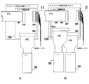
図3は、ヘッド接続基板10(10A又は10B)にFFC及びセンサ用ハーネス15を接続した状態を示す図である。
図3Aは1個のインクジェットヘッド実装用のヘッド接続基板10Aをキャリッジ8内部に設置した場合を示す。図3Bは2個のインクジェットヘッド実装用のヘッド接続基板10Bをキャリッジの所定エリアに配置する場合を示している。
FIG. 3 is a diagram illustrating a state in which the FFC and the
FIG. 3A shows a case where one
本実施形態によれば、図3に示すように、キャリッジ8の実装エリアにヘッド接続基板10A又は10Bを設置したときに、ヘッド制御信号用FFCコネクタCN2とCN7の位置が同じである。そのため、ヘッド制御信号用FFCを共通化することができる。
同様に、ヘッド接続FPCコネクタCN4とCN9の位置が同じであるため、ヘッド接続FPCを共通化することができる。また、センサ用ハーネス及びヘッド駆動信号用FFCコネクタCN1とCN5に接続するヘッド駆動信号用FFCも共通化することができる。
According to the present embodiment, as shown in FIG. 3, when the
Similarly, since the positions of the head connection FPC connectors CN4 and CN9 are the same, the head connection FPC can be shared. Also, the sensor harness and the head drive signal FFC connected to the head drive signal FFC connectors CN1 and CN5 can be shared.
以上で説明した実施形態によれば、同じFFCで複数の信号を転送してもノイズが発生する虞がない場合は、FFCの空きピンを利用して同じFFCで複数の信号を転送するようにする。これによりコネクタの数が減り、2個のヘッドを実装するヘッド接続基板のサイズを縮小することができる。また、実装するヘッドの数が相違する場合であっても、それぞれキャリッジ8の実装エリアに配置された状態において、ヘッド接続基板上に配置するFFCコネクタ、ヘッド接続FPCコネクタ、センサ用ハーネス用コネクタの位置をヘッドが1個の場合を基本に、共通のコネクタは同じ位置に配置したことで、使用するFFC等をヘッドの数によらず可能な限り共通化することができる。そのため、ヘッド接続基板の設置コストを削減することができ、延いてはインクジェットプリンタを製造する場合の全体のコストを抑制することができる。 According to the embodiment described above, when there is no possibility that noise is generated even if a plurality of signals are transferred by the same FFC, a plurality of signals are transferred by the same FFC by using the free pins of the FFC. To do. As a result, the number of connectors is reduced, and the size of the head connection board on which two heads are mounted can be reduced. Even when the number of heads to be mounted is different, the FFC connector, the head connection FPC connector, and the sensor harness connector arranged on the head connection board are arranged in the mounting area of the carriage 8 respectively. Since the common connector is arranged at the same position on the basis of the case of one head, the FFC to be used can be made as common as possible regardless of the number of heads. Therefore, the installation cost of the head connection substrate can be reduced, and the overall cost when manufacturing the ink jet printer can be suppressed.
なお、以上の説明では、1個のヘッドと2個のヘッドのそれぞれの実装ヘッド接続基板において、共通のコネクタについては、それぞれキャリッジ8内部に設置された状態において、同じ配置位置にするものとして説明したが、それは最良の形態であって、本発明は、その一部のコネクタの配置位置が同じであってもよい。
また、ヘッド接続基板に接続されるヘッドは必ずしも2個に限定されない。この場合においても、ヘッド1個実装のヘッド接続基板におけるコネクタの配置位置を基準にヘッド2個以上の各コネクタの配置位置を定める。
In the above description, it is assumed that the common connectors on the mounting head connection boards of the one head and the two heads are arranged in the same position in the state of being installed inside the carriage 8. However, it is the best mode, and in the present invention, the arrangement positions of some of the connectors may be the same.
Further, the number of heads connected to the head connection substrate is not necessarily limited to two. Even in this case, the arrangement positions of the connectors having two or more heads are determined based on the arrangement positions of the connectors on the head connection board mounted with one head.
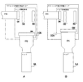
図4は、図2、3に示すヘッド接続基板において、さらにコストを削減するための手法について説明する図である。
なお、図4では、1個のインクジェットヘッド実装用ヘッド接続基板10(10A又は10A´)をキャリッジの所定エリアに配置する場合を例に採り説明するが、2個以上のインクジェットヘッド実装用ヘッド接続基板10(10B又は10B´)をキャリッジの所定エリアに配置する場合も同様に考えることができる。
FIG. 4 is a diagram for explaining a method for further reducing the cost in the head connection substrate shown in FIGS.
In FIG. 4, a case where one inkjet head mounting head connection substrate 10 (10A or 10A ′) is arranged in a predetermined area of the carriage will be described as an example. However, two or more inkjet head mounting head connections are described. The same applies to the case where the substrate 10 (10B or 10B ′) is arranged in a predetermined area of the carriage.
図4Aは、図2Aと同じヘッド接続基板10Aであり、図4Bに示すヘッド接続基板10A´との比較の対象として示すものである。
図4Aでは、FPCのコストがヘッド接続基板10Aのコストよりもインクジェットプリンタ100の製造コストに与える影響が大きいことを前提に、ヘッド接続FPCコネクタCN4をインクジェットヘッド9Aに近い位置に設計することで、FPCを短くする構成としている。
4A is the same
In FIG. 4A, on the assumption that the cost of the FPC has a greater influence on the manufacturing cost of the
一方、図4Bでは、ヘッド接続基板10A´のコストがFPCのコストよりもインクジェットプリンタ100の製造コストに与える影響が大きいことを前提に、ヘッド接続基板10A´を縦方向に縮小し、FPCを長くする構成としている。
このように、FPCのコストとヘッド接続基板のコストを比較考慮した上で、ヘッド接続基板のサイズを変更することで、ヘッド接続基板の製造コストをさらに削減することができる。
On the other hand, in FIG. 4B, assuming that the cost of the
In this way, the manufacturing cost of the head connection board can be further reduced by changing the size of the head connection board in consideration of the cost of the FPC and the cost of the head connection board.
以上、説明したように、本発明の実施形態に係るヘッド接続基板によれば、キャリッジ内部に2個のインクジェットヘッド実装用のヘッド接続基板を配置した状態において、ヘッドの増設に伴い増設が必要となるコネクタを除き、1個のインクジェットヘッド実装用のヘッド接続基板における各コネクタの配置位置と同じ配置位置になるような構造を採用したため、各種ケーブルを各ヘッド接続基板で共通化できる。これにより、ヘッド接続基板、延いては画像形成装置(インクジェットプリンタ)の製造コストを低減することができる。 As described above, according to the head connection board according to the embodiment of the present invention, it is necessary to increase the number of head connection boards when the head connection boards for mounting two inkjet heads are arranged inside the carriage. Except for the connector, since a structure is adopted in which the position of each connector is the same as the position of each connector in a head connection board for mounting an inkjet head, various cables can be shared by each head connection board. Thereby, it is possible to reduce the manufacturing cost of the head connection substrate, and thus the image forming apparatus (inkjet printer).
10…ヘッド接続基板、CN1…ヘッド駆動信号用FFCコネクタ、CN2…ヘッド制御信号用FFCコネクタ、CN3…センサ用コネクタ、CN4…ヘッド接続FPCコネクタ、CN5…ヘッド駆動信号用FFCコネクタ、CN6…ヘッド駆動信号用FFCコネクタ、CN7…ヘッド制御信号用FFCコネクタ、CN8…センサ用コネクタ、CN9…ヘッド接続FPCコネクタ、CN10…ヘッド接続FPCコネクタ。
DESCRIPTION OF
Claims (6)
前記ヘッド駆動信号用コネクタと前記ヘッド制御信号用コネクタとは別のコネクタとして構成されており、
前記各コネクタの少なくとも1つは、当該ヘッド接続基板が前記実装エリアに配置されたとき、1個のヘッドを実装するヘッド接続基板を前記実装エリアに配置するときの当該ヘッド接続基板における対応するコネクタの位置と同じ位置になるように位置決めされたヘッド接続基板。 A head connection board that includes a head connector connected to a plurality of heads, a head drive signal connector, and a head control signal connector, and is disposed in a predetermined mounting area of the image forming apparatus,
The head drive signal connector and the head control signal connector are configured as separate connectors,
At least one of the connectors is a connector corresponding to the head connection board when a head connection board for mounting one head is arranged in the mounting area when the head connection board is arranged in the mounting area. The head connection substrate positioned so as to be in the same position as the position.
1個のヘッドを実装するヘッド接続基板に対して、ヘッドの増設数に伴い増設が必要となるコネクタ以外のコネクタは、ヘッド接続基板が前記実装エリアに配置されたとき、前記1個のヘッドを実装するヘッド接続基板における対応するコネクタの位置と同じ位置になるように位置決めされたヘッド接続基板。 A head connection board that includes a head connector connected to a plurality of heads, a head drive signal connector, and a head control signal connector, and is disposed in a predetermined mounting area of the image forming apparatus,
With respect to the head connection board on which one head is mounted, a connector other than the connector that needs to be added in accordance with the number of heads added, the head connection board is arranged when the head connection board is arranged in the mounting area. A head connection board positioned so as to be in the same position as the corresponding connector on the head connection board to be mounted.
センサ用コネクタを備え、
前記センサ用コネクタが、前記ヘッド接続基板が前記所定の実装エリアに配置されたとき、複数のセンサに接続され1個のヘッドを実装するヘッド接続基板におけるセンサ用コネクタと同じ位置になるよう位置決めされたヘッド接続基板。 In the head connection substrate according to claim 2,
With sensor connector,
The sensor connector is positioned to be in the same position as the sensor connector on the head connection board that is connected to a plurality of sensors and mounts one head when the head connection board is disposed in the predetermined mounting area. Head connection board.
前記ヘッド接続基板のヘッド駆動信号用コネクタ及びヘッド制御信号用コネクタはFFCを介して前記画像形成装置の制御部に接続されている画像形成装置。 The image forming apparatus according to claim 4.
The image forming apparatus in which the head drive signal connector and the head control signal connector of the head connection substrate are connected to the control unit of the image forming apparatus via an FFC.
前記ヘッド制御信号用コネクタに接続されるFFCは、複数のセンサに対するセンサの制御信号を転送する画像形成装置。 The image forming apparatus according to claim 5.
The FFC connected to the head control signal connector is an image forming apparatus that transfers sensor control signals to a plurality of sensors.
Priority Applications (1)
| Application Number | Priority Date | Filing Date | Title |
|---|---|---|---|
| JP2015017752A JP2016141017A (en) | 2015-01-30 | 2015-01-30 | Head connection substrate and image formation apparatus having head connection substrate |
Applications Claiming Priority (1)
| Application Number | Priority Date | Filing Date | Title |
|---|---|---|---|
| JP2015017752A JP2016141017A (en) | 2015-01-30 | 2015-01-30 | Head connection substrate and image formation apparatus having head connection substrate |
Publications (1)
| Publication Number | Publication Date |
|---|---|
| JP2016141017A true JP2016141017A (en) | 2016-08-08 |
Family
ID=56568235
Family Applications (1)
| Application Number | Title | Priority Date | Filing Date |
|---|---|---|---|
| JP2015017752A Pending JP2016141017A (en) | 2015-01-30 | 2015-01-30 | Head connection substrate and image formation apparatus having head connection substrate |
Country Status (1)
| Country | Link |
|---|---|
| JP (1) | JP2016141017A (en) |
-
2015
- 2015-01-30 JP JP2015017752A patent/JP2016141017A/en active Pending
Similar Documents
| Publication | Publication Date | Title |
|---|---|---|
| US9180666B2 (en) | Image recording device | |
| JP7226476B2 (en) | liquid ejection head | |
| US20130201256A1 (en) | Print head die | |
| JP5760302B2 (en) | Liquid ejection device | |
| US8979229B2 (en) | Liquid jetting apparatus | |
| JP2012035573A (en) | Liquid discharge head, and image recording device and method | |
| JP2007062087A (en) | Recording unit, and image recording device equipped with the recording unit | |
| JP2009196282A (en) | Image forming apparatus | |
| JP2016141017A (en) | Head connection substrate and image formation apparatus having head connection substrate | |
| JP5707802B2 (en) | Image forming apparatus | |
| KR20130055567A (en) | Inkjet recording device | |
| JP5593281B2 (en) | Inkjet recording device | |
| JP6478807B2 (en) | Recording device | |
| JP2010046992A (en) | Liquid discharge head and recording apparatus using the liquid discharge head | |
| JP5915723B2 (en) | Liquid ejection device | |
| US8888213B2 (en) | Circuit device and droplet ejection apparatus | |
| JP5970715B2 (en) | Liquid ejection device | |
| JP2004351727A (en) | Inkjet recording device | |
| JP2012139987A (en) | Liquid ejection head and image recording apparatus | |
| JP2007076174A (en) | Recording head system | |
| JP6390729B2 (en) | Liquid ejection device | |
| JP5704215B2 (en) | Liquid ejection device | |
| JP2024031157A (en) | Liquid discharge head and recording device | |
| JP2023147123A (en) | Liquid ejection head and recording device |