JP2016129960A - Tape printing device - Google Patents
Tape printing device Download PDFInfo
- Publication number
- JP2016129960A JP2016129960A JP2015004723A JP2015004723A JP2016129960A JP 2016129960 A JP2016129960 A JP 2016129960A JP 2015004723 A JP2015004723 A JP 2015004723A JP 2015004723 A JP2015004723 A JP 2015004723A JP 2016129960 A JP2016129960 A JP 2016129960A
- Authority
- JP
- Japan
- Prior art keywords
- image
- character string
- tape
- printing
- Prior art date
- Legal status (The legal status is an assumption and is not a legal conclusion. Google has not performed a legal analysis and makes no representation as to the accuracy of the status listed.)
- Granted
Links
Images


Abstract
Description
本発明は、印字テープを作成するテープ印字装置に関する。 The present invention relates to a tape printer for producing a printing tape.
被印字テープに文字列を印字形成して印字テープを作成するテープ印字装置が知られている(例えば、特許文献1参照)。このテープ印字装置においては、搬送手段(テープ送りローラ)で搬送される被印字テープ(印字テープ)に対し、印字手段(サーマルヘッド)によって印字が形成されることで、印字テープが作成される。その際、印字テープには、操作者が入力したテキスト文字と、そのテキスト文字を包囲して修飾する枠と、が印字形成可能となっている。 2. Description of the Related Art A tape printer that prints a character string on a print-receiving tape to create a print tape is known (see, for example, Patent Document 1). In this tape printer, a print tape is created by forming a print on a print-receiving tape (print tape) transported by a transport means (tape feed roller) by a print means (thermal head). At this time, text characters input by the operator and a frame surrounding and modifying the text characters can be printed on the print tape.
しかしながら、上記従来技術で、文字列を包囲して修飾することはできるものの、文字列中の文字と文字との間に空白部が存在したとき、その空白部にはなんの修飾もなされなかった。したがって修飾効果が十分とは言えなかった。 However, with the above prior art, it is possible to surround and modify a character string, but when a blank portion exists between characters in the character string, no modification is made to the blank portion. . Therefore, the modification effect was not sufficient.
本発明の目的は、文字列中の空白部に対しデザイン性を持たせ、修飾効果を高めることができる、テープ印字装置を提供することにある。 An object of the present invention is to provide a tape printer that can give a design property to a blank portion in a character string and enhance a modification effect.
上記目的を達成するために、本願発明は、被印字テープを搬送させるための搬送手段と、前記搬送手段により搬送される前記被印字テープに対し、印字を形成する印字手段と、を有し、印字形成後の前記被印字テープにより印字テープを作成するテープ印字装置であって、前記印字テープに対し印字形成される、複数の文字からなる文字列を操作入力するための文字列入力手段と、前記印字テープにおいて前記文字列とともに形成するために予め用意された、複数の第1画像を記憶した第1記憶手段と、前記文字列入力手段により操作入力された前記文字列において文字と文字の間に文字のない第1空白部が存在するか否かを判定する第1判定手段と、前記第1判定手段により前記第1空白部が存在すると判定された場合に、前記第1記憶手段に記憶された前記複数の第1画像の中から、前記文字列の前記当該第1空白部に挿入する第1画像を選択する第1画像選択手段と、前記第1画像選択手段により選択された前記第1画像を、前記文字列の前記第1空白部に挿入した印字データを生成する印字データ生成手段と、前記搬送手段及び前記印字手段を連携して制御し、前記印字データに対応した印字が形成された前記印字テープを作成する連携制御手段と、を有することを特徴とする。 In order to achieve the above object, the present invention has a conveying means for conveying a print-receiving tape, and a printing means for forming a print on the print-receiving tape conveyed by the conveying means, A tape printing apparatus for creating a printing tape from the tape to be printed after printing is formed, and a character string input means for operating and inputting a character string composed of a plurality of characters that is printed on the printing tape; A first storage means for storing a plurality of first images prepared in advance for forming together with the character string on the printing tape, and between characters in the character string operated and input by the character string input means. A first determination unit for determining whether or not there is a first blank part having no character, and the first storage unit when the first determination unit determines that the first blank part is present. Selected from the plurality of first images stored in the first image selection means for selecting a first image to be inserted into the first blank portion of the character string, and selected by the first image selection means A print data generation unit that generates print data inserted into the first blank portion of the character string, the transport unit, and the print unit are controlled in cooperation with each other to print corresponding to the print data. And a linkage control means for producing the printing tape on which is formed.
本願発明では、操作者が操作入力した文字列を構成する複数の文字において文字と文字との間に空白部(第1空白部)があった場合、第1判定手段の判定が満たされ、第1画像選択手段によって当該第1空白部に挿入される第1画像が選択される。そして、印字データ生成手段は、文字列中の上記第1空白部に上記選択された第1画像が挿入された印字データを生成する。これにより、連携制御手段の制御によって、上記文字列の複数の文字が形成されるとともに上記第1空白部に上記第1画像が形成された、印字テープが作成される。この結果、文字列中の空白部にもデザイン性を持たせて、修飾効果を高めることができる。したがって、印字テープの表現力を増大させることができるので、操作者の利便性を向上することができる。 In the present invention, when there is a blank portion (first blank portion) between characters in a plurality of characters constituting the character string operated and input by the operator, the determination of the first determination means is satisfied, The first image to be inserted into the first blank portion is selected by the one image selection means. Then, the print data generating means generates print data in which the selected first image is inserted in the first blank portion in the character string. As a result, a printing tape is formed in which a plurality of characters of the character string are formed and the first image is formed in the first blank portion under the control of the cooperation control unit. As a result, the blank portion in the character string can be given a design and the modification effect can be enhanced. Therefore, since the expressive power of the printing tape can be increased, the convenience for the operator can be improved.
本発明によれば、文字列中の空白部に対しデザイン性を持たせ、修飾効果を高めることができる。 According to the present invention, it is possible to give designability to the blank portion in the character string and enhance the modification effect.
以下、本発明の一実施形態を図面を参照しつつ説明する。 Hereinafter, an embodiment of the present invention will be described with reference to the drawings.
<テープ印字装置の概略構成>
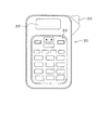
本実施形態のテープ印字装置20を図1に示す。図1において、テープ印字装置20は、例えば液晶ディスプレイからなり各種情報や各種メッセージを表示する表示部22と、操作者が各種操作を可能な操作部23と、装置本体内に配設されたカッタ27(後述の図2参照)を駆動するためのカットレバー24とを備えている。
<Schematic configuration of tape printer>
A
操作部23には、文字、記号、及び数字等を入力するための入力キー、印字ラベルLの作成開始を指示するための印刷キー、装置電源をオン・オフするための電源ボタン、等を含む種々のキー・ボタン等が含まれている。
The
<テープ印字装置の機能的構成>
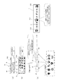
テープ印字装置20の機能的構成を図2に示す。図2において、テープ印字装置20は、制御回路25と、各種情報を記憶するメモリ26(第1記憶手段、第2記憶手段に相当)と、上記表示部22と、上記操作部23と、上記カットレバー24と、カートリッジホルダ32と、プラテンローラ29(搬送手段に相当)と、サーマルヘッド30(印字手段に相当)と、カッタ27とを有する。
<Functional configuration of tape printer>
A functional configuration of the
制御回路25は、図示しないCPU、RAM、及びROMを備えている。この制御回路25は、RAMの一時記憶機能を利用しつつ、ROMに予め記憶された各種プログラムを実行する。これにより、制御回路25は、テープ印字装置20全体の制御を行う。
The
メモリ26は、記憶内容の追加及び消去が可能な、例えばEEPROM等の不揮発性メモリから構成されている。このメモリ26には、予め用意された複数の挿入用画像等が格納されている(詳細は後述)。
The
カートリッジホルダ32は、被印字テープ33を供給可能なカートリッジ31を着脱可能に構成されている。カートリッジ31は、被印字テープ33を図示しないリール部材(スプール)の周りに巻回したテープロール34(本来は渦巻き状であるが簡略化して同心円で図示している)を備えている。
The
プラテンローラ29は、サーマルヘッド30に対向して設けられている。このプラテンローラ29は、制御回路25により制御される駆動モータの駆動力により回転し、カートリッジホルダ32に装着したカートリッジ31のテープロール34から被印字テープ33を繰り出し、繰り出した被印字テープ33を搬送する。
The
サーマルヘッド30は、制御回路25の制御に基づき、プラテンローラ29によりテープロール34から繰り出されて搬送される被印字テープ33に対し、所望の印字を形成する。
Under the control of the
カッタ27は、操作者によりカットレバー24が操作されることで、サーマルヘッド30による印字が終了した被印字テープ33を切断し、印字ラベルL(印字テープに相当。後述の図3等参照)とする。
When the operator operates the
上記構成において、カートリッジ31がカートリッジホルダ32に装着されると、プラテンローラ29がサーマルヘッド30に押圧され、テープロール34から繰り出された被印字テープ33がプラテンローラ29とサーマルヘッド30との間に狭持される。そして、図示しない駆動モータの駆動力によってプラテンローラ29が回転し、被印字テープ33がプラテンローラ29とサーマルヘッド30との間を通って搬送される。このとき、制御回路25によりサーマルヘッド30に設けられた複数の発熱素子(図示せず)が通電され、発熱する。この結果、サーマルヘッド30により被印字テープ33に、所望の印字内容の印字データ(詳細は後述)に対応した印字が印刷される。
In the above configuration, when the
その後、上記カットレバー24が操作されることにより、カッタ27が印字が終了した被印字テープ33が切断され、上記印字ラベルLが生成される。
Thereafter, when the
<実施形態の特徴>
上記構成のテープ印字装置20において、本実施形態の特徴は、文字列中の空白部に適宜の挿入用画像(詳細は後述)を形成した印字ラベルを作成することにある。
<Features of the embodiment>
In the
<印字ラベル作成の具体例>
すなわち、例えばユーザ(操作者に相当)が操作部23の上記電源ボタンをオンすると、図3(a)に示すように、上記表示部22に、テキスト文字等の入力を行うためのテキスト入力部40を有するテキスト編集画面40Aが表示される。この状態で、ユーザは、操作部23の上記入力キーを用いて、テキスト入力部40にテキスト文字の入力を行う。この例では、入力されたテキスト文字は、男の子の名前を平仮名で表した「のむら ひろき」の文字列Rである。文字列Rには、文字「ら」と文字「ひ」との間(言い換えれば文字列Rの中間部)に、文字のない空白部41(第1空白部に相当)が存在している。
<Specific example of printing label creation>
That is, for example, when a user (corresponding to an operator) turns on the power button of the
その後、ユーザが操作部23を適宜に操作することで、図3(b)に示すように、表示部22に、グループ選択画面42Aが表示される。このグループ選択画面42Aには、それぞれが複数の挿入用画像を含む複数の画像グループGが、(例えばスクロール操作することで)一覧可能に表示される。
Thereafter, when the user appropriately operates the
<挿入用画像の画像グループ>
これら複数の画像グループ及びそれぞれに属する挿入用画像の例を、図4に示す。図4に示すように、この例では、上記画像グループG(群に相当)として、「男の子」グループ、「女の子」グループ、「動物」グループ、「夏」グループ、「冬」グループ、「誕生日」グループの6つが予め用意されている。「男の子」グループは、男の子向きの乗り物やおもちゃ等を表すために予め用意された11個の画像101〜111を含んでおり、「女の子」グループは、女の子向きのアクセサリーや花等を表すために予め用意された11個の画像121〜31を含んでおり、「動物」グループは、代表的な動物を表すために予め用意された9個の画像141〜149を含んでおり、「夏」グループは、夏の季節感を表すために予め用意された9個の画像151〜159を含んでおり、「冬」グループは、冬の季節感を表すために予め用意された6個の画像161〜166を含んでおり、「誕生日」グループは、誕生日イベントを表すために予め用意された6個の画像171〜176を含んでいる。上記画像101〜111,121〜131,141〜149,151〜159,161〜166,171〜176(第1画像に相当)は、予め各グループに対応づけられた形で上記メモリ26に記憶されている。
<Image group of images for insertion>
Examples of the plurality of image groups and insertion images belonging to each of the plurality of image groups are shown in FIG. As shown in FIG. 4, in this example, as the image group G (corresponding to a group), “boy” group, “girl” group, “animal” group, “summer” group, “winter” group, “birthday” Six groups are prepared in advance. The “boy” group includes eleven
図3に戻り、上記グループ選択画面42Aでは、上記「男の子」グループ、「女の子」グループ、「動物」グループ、「夏」グループ、「冬」グループ、及び「誕生日」グループの全ての画像グループGが、ユーザの操作部23への適宜の操作により選択可能に表示される。図3(b)に示す例では、各画像グループGは、それぞれに属する挿入用画像(各グループに属する全画像でもよいし、それらのうち代表的なものだけでもよい)を含む形で表示されている。なお、グループ名等のテキスト表示等のみを、選択可能に表示してもよい。
Returning to FIG. 3, on the
上記複数の画像グループGがグループ選択画面42Aに表示された状態で、ユーザは、操作部23の適宜の操作により、自らがこれから作成しようとする印字ラベルLに適用させる画像グループGを1つ指定する。この例では、上記「男の子」グループが指定された例を示している。
In a state where the plurality of image groups G are displayed on the
その後、ユーザが、操作部23中の上記印刷キーを押して印字ラベルLの作成開始を指示することで、図3(c)に示すように、上記指定された画像グループG(この例では「男の子」グループ)からアトランダムに1つの挿入用画像が選択される。この例では、野球帽の画像106(図4参照)が選択されている。そして、その選択された画像106を文字列R中の上記空白部41に挿入した印字データが生成される。このような印字データが生成されることにより、当該印字データを用いて作成された印字ラベルLには、「のむら ひろき」の複数の文字が印字形成されるとともに、文字「ら」と文字「ひ」との間の空白部に上記画像106が印字形成される。
Thereafter, the user presses the print key in the
なお、文字列Rの中間部(文字列の真ん中とは限らない)に空白部41が複数箇所ある場合には、それぞれに対し上記のようにしてアトランダムに挿入用画像が選択される。そして、それら選択された画像を文字列R中の複数の空白部41にそれぞれ挿入した印字データが生成され、印字ラベルLにおいて文字間の複数箇所の空白部にそれぞれ上記画像が印字形成される。
When there are a plurality of
<制御手順>
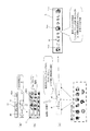
以上説明した本実施形態の手法を実現するために、制御回路25によって実行される処理手順を表すフローを図5に示す。
<Control procedure>
FIG. 5 shows a flow representing a processing procedure executed by the
図5において、例えばユーザが操作部23の上記電源ボタンの操作によりテープ印字装置20の電源をオンすることにより、このフローが開始される。
In FIG. 5, for example, when the user turns on the
まず、ステップS5において、制御回路25は、表示部22に制御信号を出力し、表示部22に前述のテキスト編集画面40Aを表示させる(上記図3(a)参照)。ステップS5が終了すると、ステップS10に移る。
First, in step S5, the
ステップS10では、制御回路25は、ユーザが操作部23を用いて行ったテキスト編集画面40Aでの文字列Rの入力操作を受付ける。前述の例では、文字列R「のむら ひろき」の入力が受け付けられる(上記図3(a)参照)。なお、このときの操作部23が、各請求項記載の文字列入力手段として機能している。ステップS10が終了すると、ステップS15に移る。
In step S <b> 10, the
ステップS15では、制御回路25は、ユーザが操作部23を用いて行った、グループ選択画面42A中の画像グループGの指定を受付ける。なお、このときの操作部23が、各請求項記載の第1操作手段として機能している(なお、後述の変形例(1)では、第2操作手段として機能する)。前述の例では、複数の画像グループG中の「男の子」グループの指定が受け付けられる(上記図3(b)参照)。ステップS15が終了すると、ステップS20に移る。
In step S <b> 15, the
ステップS20では、制御回路25は、ユーザにより操作部23中の上記印刷キーが押されたか否かを判定する。ユーザにより印刷キーが押されなければステップS20の判定が満たされず(ステップS20:NO)、上記ステップS10へ戻って同様の手順を繰り返す。ユーザにより印刷キーが押されればステップS20の判定が満たされ(ステップS20:YES)、ステップS25に移る。なお、このときの操作部23が、各請求項記載の第3操作手段として機能している。
In step S20, the
ステップS25では、制御回路25は、上記ステップS10で入力を受け付けた文字列Rの中間に空白部があるか否かを判定する。前述の例では、受け付けられた文字列R「のむら ひろき」において、文字「ら」と文字「ひ」との間に空白部41が存在する(図3(a)、図3(c)参照)。このように文字列Rの中間に空白部がある場合はステップS25の判定が満たされ(ステップS25:YES)、ステップS30に移る。一方、入力を受け付けた文字列Rの中間に空白部がない場合はステップS25の判定が満たされず(ステップS25:NO)、後述のステップS35に移る。なお、このステップS25を実行する制御回路25が、各請求項記載の第1判定手段として機能する。
In step S25, the
ステップS30では、制御回路25は、上記ステップS15で指定を受け付けた画像グループG中の複数の挿入用画像のうち1つを、アトランダムに選択する。前述の例では、指定された上記「男の子」グループ中の上記画像106が選択される(図3(c)参照)。なお、前述のステップS15を省略し、ステップS10での文字列Rの入力を受け付けた後、ステップS20及びステップS25を経て、このステップS30で1つの挿入用画像をアトランダムに選択するようにしてもよい。この場合は、例えばメモリ26に記憶されているすべての画像(前述の例では画像101〜111,121〜131,141〜149,151〜159,161〜166,171〜176)から、アトランダムに1つが選択される。あるいは全画像のうち適宜の複数の画像から選択されてもよい。ステップS30が終了すると、ステップS35に移る。なお、このステップS30を実行する制御回路25が、各請求項記載の第1画像選択手段として機能する。
In step S30, the
ステップS35では、制御回路25は、これまでの処理を反映した形で印字データを生成する。すなわち、文字列Rの中間に上記空白部41がありステップS30での挿入用画像の選択を経てステップS35に移行した場合には、制御回路25は、文字列R中の上記空白部41に対し上記選択された挿入用画像(前述の例では画像106)を挿入した態様の、印字データを生成する。一方、文字列Rの中間に上記空白部41がなくステップS25の判定が満たされずにステップS35に移行した場合には、制御回路25は、そのまま文字列Rの文字に対応する印字データを生成する。なお、このステップS35を実行する制御回路25が、各請求項記載の印字データ生成手段として機能する。ステップS35が終了すると、ステップS40に移る。
In step S35, the
ステップS40では、制御回路25は、プラテンローラ29の上記駆動モータに制御信号を出力し(あるいは適宜のモータ駆動回路を介して制御信号を出力してもよい。以下同様)、プラテンローラ29による上記被印字テープ33の搬送を開始する。その後、ステップS45に移る。
In step S40, the
ステップS45では、制御回路25は、上記ステップS35で生成された印字データに基づき、被印字テープ33が所定の印字領域開始位置まで搬送されたか否か(言い換えれば、被印字テープ33の所定の印字領域の前端にサーマルヘッド30が正対する搬送方向位置になるまで被印字テープ33が搬送された否か)を判定する。この判定は、例えばステッピングモータからなる上記駆動モータのパルス数をカウントする等、公知の適宜の手法により行えば足りる。被印字テープ33が印字領域の開始位置まで搬送されていなければステップS45の判定が満たされず(ステップS45:NO)、ステップS45の判定が満たされるまでループ待機する。被印字テープ33が印字領域の開始位置まで搬送されたらステップS45の判定が満たされ(ステップS45:YES)、ステップS50に移る。
In step S45, the
ステップS50では、制御回路25は、上記ステップS35で生成された印字データに基づきサーマルヘッド30の上記発熱素子に通電し、印字処理を行う。これにより、被印字テープ33上に上記印字データに対応した印字が形成される。その後、ステップS55に移る。
In step S50, the
ステップS55では、制御回路25は、被印字テープ33が上記印字領域の終了位置まで搬送されたかどうか(言い換えれば、上記印字領域の後端にサーマルヘッド30が正対する搬送方向位置になるまで被印字テープ33が搬送されたか否か)を判定する。この判定も上記同様の公知の手法により行えば足りる。被印字テープ33が印字領域の終了位置まで搬送されていなければステップS55の判定が満たされず(ステップS55:NO)、ステップS50に戻って同様の手順を繰り返す。被印字テープ33が印字領域の終了位置まで搬送されていればステップS55の判定が満たされ(ステップS55:YES)、ステップS60に移る。
In step S55, the
ステップS60では、制御回路25は、上記ステップS35で生成された印字データに基づき、印字が終了した印字済みの被印字テープ33が、上記印字領域よりラベル後端側に設定される所定の切断位置まで搬送されたか否か(言い換えれば、上記切断位置に上記カッタ27が正対する搬送方向位置になるまで、印字済みの被印字テープ33が搬送されたか否か)を判定する。この判定も、前述と同様の公知の手法により行えば足りる。印字済みの被印字テープ33が切断位置まで搬送されていなければステップS60の判定が満たされず(ステップS60:NO)、ステップS60の判定が満たされるまでループ待機する。印字済みの被印字テープ33が切断位置まで搬送されたらステップS60の判定が満たされ(ステップS60:YES)、ステップS65に移る。なお、上記ステップS40〜ステップS65を実行する制御回路25が、各請求項記載の連携制御制御手段として機能する。
In step S60, based on the print data generated in step S35, the
ステップS65では、制御回路25は、プラテンローラ29の上記駆動モータに制御信号を出力し、プラテンローラ29による被印字テープ33の搬送を停止する。ステップS65が終了すると、ステップS70に移る。
In step S <b> 65, the
ステップS70では、制御回路25は、表示部22に制御信号を出力し、表示部22により、ユーザに対し印字済みの被印字テープ33の切断を促す表示を行わせる。これにより、ユーザがカットレバー24を操作することで、印字済み被印字テープ33の切断が行われ、上記ステップS35で生成された印字データに基づく印字が形成された印字ラベルLが生成される。すなわち、文字列R中に上記空白部がない場合には、文字列Rを構成する複数の文字のみが印字形成された印字ラベルLが生成される。文字列R中に空白部がある場合には、文字列Rを構成する複数の文字が印字形成されるとともに、空白部に上記ステップS30で選択された挿入用画像(前述の例では、野球帽の画像106)が印字形成された印字ラベルLが生成される(図3(c)参照)。その後、このフローを終了する。
In step S <b> 70, the
<実施形態の効果>
以上説明したように、本実施形態のテープ印字装置20では、印字ラベルLの作成の際、操作部23により操作入力された文字列Rにおいて文字と文字の間に文字のない空白部41が存在するか否かが判定される。そして、空白部41が存在すると判定された場合には、メモリ26に記憶された複数の挿入用画像の中から1つが選択され、選択された挿入用画像を文字列Rの空白部41に挿入した印字データが生成され、この印字データに対応した印字ラベルLが作成される。これにより、印字ラベルLにおける文字列R中の空白部にもデザイン性を持たせて、修飾効果を高めることができる。したがって、印字ラベルLの表現力を増大させることができ、ユーザの利便性を向上することができる。なお、例えば空白部41の大きさが比較的大きい等の場合には、複数の挿入用画像を挿入するようにしてもよい。
<Effect of embodiment>
As described above, in the
また、本実施形態では特に、複数の挿入用画像が、予め定められた複数の画像グループGに分類されている。そして、ユーザが、操作部23の操作によって1つの画像グループGを指定することで、当該指定された画像グループGに対応した1つの挿入用画像が選択され、上記空白部41に挿入される。これにより、ユーザが操作部23を介して自らの好みや意図に応じた画像グループGを指定することで、その好みや意図に適合した挿入用画像を印字ラベルLに形成することができる。なお、上記の例では、ユーザにより指定された1つの画像グループGに含まれる複数の挿入用画像の中からアトランダムに1つの画像が選択されたが、これに限られない。すなわち、ユーザにより指定された1つの画像グループGに含まれる複数の挿入用画像の中から、所定の規則性に基づき(例えば各画像の識別番号順等)、1つの画像が選択されるようにしてもよい。あるいは1つの画像グループGの指定に対して、特定の1つの画像(例えば代表画像)が選択されるようにしてもよい。これらの場合も同様の効果を得る。
In the present embodiment, in particular, a plurality of insertion images are classified into a plurality of predetermined image groups G. Then, when the user designates one image group G by the operation of the
<各種変形例>
なお、本発明は、上記実施形態に限られるものではなく、その趣旨及び技術的思想を逸脱しない範囲内で種々の変形が可能である。以下、そのような変形例を順を追って説明する。なお、上記実施形態と同等の部分には同一の符号を付し、適宜説明を省略又は簡略化する。
<Various modifications>
The present invention is not limited to the above-described embodiment, and various modifications can be made without departing from the spirit and technical idea of the present invention. Hereinafter, such modifications will be described in order. In addition, the same code | symbol is attached | subjected to the part equivalent to the said embodiment, and description is abbreviate | omitted or simplified suitably.
(1)文字列の前部及び後部にも空白部がある場合
上記実施形態では、ユーザが操作入力した文字列Rの中間部に文字のない空白部41があった場合に、その空白部41に挿入用画像を挿入したが、これに限られない。すなわち、操作入力した文字列Rの前部及び後部に空白部がある場合には、その前部及び後部の空白部にも挿入用画像を挿入することができる。
(1) When there are blank portions at the front and rear portions of the character string In the above embodiment, when there is a
<印字ラベル作成の具体例>
すなわち、上記実施形態の図3に対応する図6において、ユーザが操作部23の電源ボタンをオンすると、上記図3(a)同様、まず、図6(a)に示すように、上記表示部22に、上記テキスト編集画面40Aが表示される。この状態で、ユーザは、上記操作部23を用いて、テキスト入力部40にテキスト文字の入力を行う。この例では、入力されたテキスト文字は、男性の名前を平仮名で入力した「 ささき かずひろ 」の文字列Rである。そして、この文字列Rには、文字「ら」と文字「ひ」との間に空白部41が存在する他に、最初の文字「さ」の前、最後の文字「ろ」の後に、それぞれ空白部43,44(第2空白部に相当)が存在する。
<Specific example of printing label creation>
That is, in FIG. 6 corresponding to FIG. 3 of the above-described embodiment, when the user turns on the power button of the
その後、前述と同様、ユーザが操作部23を適宜に操作することにより、図6(b)に示すように、表示部22に、グループ選択画面42Aが表示される。ユーザは、操作部23の適宜の操作により、自らがこれから作成しようとする印字ラベルLに適用させる画像グループGを1つ指定する。この例では、前述の複数の画像グループGのうち、「夏」グループが指定された例を示している。
Thereafter, as described above, when the user appropriately operates the
その後、ユーザが、操作部23中の上記印刷キーを押して印字ラベルLの作成開始を指示することで、図6(c)に示すように、上記指定された画像グループG(この例では「夏」グループ)から、上記文字列R中の空白部41に挿入する1つの挿入用画像(第1画像に相当)と、前後の空白部43,44にそれぞれ挿入する2つの挿入用画像(第2画像に相当)と、がアトランダムに選択される。この例では、文字列Rの中間部の空白部41に対してはビールジョッキの画像154(前述の図4も参照)が選択され、文字列Rの前の空白部43に対してはテントの画像156(前述の図4も参照)が選択され、後の空白部44に「夏」グループ中のヨットの画像155(前述の図4も参照)が選択されている。そして、これら選択された画像154,156,155を上記空白部41,43,44にそれぞれ挿入した印字データが生成される。このような印字データが生成されることにより、当該印字データを用いて作成された印字ラベルLには、「 ささき かずひろ 」の複数の文字が印字形成されるとともに、「 ささき かずひろ 」の文字「さ」の前の空白部にテントの画像156が、文字「き」と文字「か」との間の空白部にビールジョッキの画像154が、文字「ろ」の後の空白部にヨットの画像155がそれぞれ印字形成される。
Thereafter, the user presses the print key in the
なお、上記においては、文字列Rの前後の空白部42,43に挿入する挿入用画像は、文字列Rの中間の空白部41に挿入する挿入用画像と共通の、図4に示される複数の画像から選択されたが、これに限られない。すなわち、空白部42,43への挿入用画像は、メモリ23に予め記憶された、図4とは別の複数の画像(予め複数の画像グループに分類された態様でモリ23に記憶されている)から選択されていてもよい。この場合、図6(b)に示すグループ選択画面42Aにおいてはその複数の画像グループが表示され、ユーザはその中から所望の1つの画像グループを選択する。
In the above description, the insertion images to be inserted into the
また、上記においては、文字列Rの前後に設けた空白部42,43に対応して2つの画像156,155が選択され、それら画像156,155が印字形成されたが、これに限られない。すなわち、図7(a)に示すように、テキスト編集画面40Aにおいて(前後に上記空白部43,44のない)「ごんどう ひろし」の文字列Rが入力された場合であっても、選択された「夏」グループ(図7(b))に対応し、上記文字列R中の空白部41に画像154が選択されるのに加えて、文字列Rの前後に配置するための2つの画像(画像156,155)がさらに選択されるようにしてもよい。この場合、上記同様、画像154が「う」と「ひ」の間の空白部41に挿入されるとともに、「ご」の前に画像156が挿入され、さらに「し」の後に画像155が挿入された印字データが生成され、対応する印字ラベルが生成される(図7(c))。
In the above description, two
<制御手順>
本変形例の手法を実現するために、制御回路25によって実行される処理手順を表すフローを図8に示す。図8のフローチャートは、図5のステップS30とステップS35との間に、新たにステップS32、ステップS34を付加した点が異なる。
<Control procedure>
FIG. 8 shows a flow representing a processing procedure executed by the
図8において、図5と同様のステップS5〜ステップS25を経て、上記ステップS30で、制御回路25は、上記図5と同様、文字列Rの中間の空白部41に挿入するために、上記ステップS15で指定を受け付けた画像グループG(前述の例では「夏」グループ)中の複数の挿入用画像から1つの画像(前述の例では画像154)を、アトランダムに選択する。その後、新たに設けたステップS32に移る。なお、前述と同様、上記ステップS15を省略し、ステップS10での文字列Rの入力を受け付けた後、ステップS20及びステップS25を経て、このステップS30で1つの挿入用画像をアトランダムに選択するようにしてもよい。
8, after steps S5 to S25 similar to those in FIG. 5, in step S30, the
ステップS32では、制御回路25は、上記ステップS10で入力を受け付けた文字列Rの前後に空白部があるか否かを判定する。前述の例では、受け付けられた文字列R「 ささき かずひろ 」は、文字「さ」の前に空白部43が存在し、文字「ろ」の後に空白部44が存在する(図6(a)、図6(c)参照)。このように文字列Rの前後に空白部がある場合はステップS32の判定が満たされ(ステップS32:YES)、新たに設けたステップS34に移る。一方、入力を受け付けた文字列Rの前後に空白部がない場合はステップS32の判定が満たされず(ステップS32:NO)、ステップS35に移る。なお、このステップS32を実行する制御回路25、各請求項記載の第2判定手段として機能する。
In step S32, the
ステップS34では、制御回路25は、上記ステップS15で指定を受け付けた画像グループG中の複数の挿入用画像から2つの挿入用画像をアトランダムに選択する。前述の例では、指定された上記「夏」グループ中の上記画像156,155が選択される(図6(c)参照)。なお、前述と同様、上記ステップS15を省略し、ステップS10での文字列Rの入力を受け付けた後、ステップS20〜ステップS32を経て、このステップS34で2つの挿入用画像をアトランダムに選択するようにしてもよい。この場合は、例えばメモリ26に記憶されているすべての画像(前述の例では画像101〜111,121〜131,141〜149,151〜159,161〜166,171〜176)から、アトランダムに2つが選択される。あるいは全画像のうち適宜の複数の画像から選択されてもよい。ステップS34が終了すると、上記ステップS35に移る。なお、このステップS34を実行する制御回路25が、各請求項記載の第2画像選択手段として機能する。
In step S34, the
ステップS35〜ステップS70は図5と同じであり、説明を省略する。 Steps S35 to S70 are the same as those in FIG.
本変形例によれば、印字ラベルLの作成の際、操作部23により操作入力された文字列Rにおいて、中間の空白部41の他に、前部及び後部に文字のない空白部43,44(第2空白部)が存在するか否かが判定される。そして、空白部43,44が存在すると判定された場合には、メモリ26に記憶された複数の挿入用画像の中から、上記空白部43,44に挿入する画像と上記空白部41に挿入する画像とが選択され、それら選択された画像を空白部41,43,44に挿入した印字データが生成され、この印字データに対応した印字ラベルLが作成される。これにより、文字列Rの複数の文字が形成され、かつ文字列R途中の空白部と文字列Rの前後の空白部にそれぞれ画像が形成された、印字ラベルLが作成される。この結果、さらに修飾効果を高め、印字ラベルLの表現力をさらに増大させることができる。
According to this modified example, when the print label L is created, in the character string R input by the
また、本変形例では、文字列Rの前後の空白部43,44に挿入される挿入用画像が、予め定められた複数の画像グループG(上記空白部41に挿入される挿入用画像と共通のグループでも別のグループでもよい)に分類されている。そして、ユーザが、操作部23の操作によって1つの画像グループGを指定することで、当該指定された画像グループGに対応した挿入用画像が選択され、上記空白部41,43,44に挿入される。これにより、ユーザが操作部23を介して自らの好みや意図に応じた画像グループGを指定することで、その好みや意図に適合した挿入用画像を印字ラベルLに形成することができる。なお、前述と同様、ユーザにより指定された1つの画像グループGに含まれる複数の挿入用画像の中から、所定の規則性に基づき(例えば各画像の識別番号順等)、上記3つの画像が選択されるようにしてもよい。あるいは1つの画像グループGの指定に対して、特定の画像(例えば予め定められた3つの代表画像)が選択されるようにしてもよい。これらの場合も同様の効果を得る。
In this modification, the insertion images inserted in the
(2)枠画像の選択に対応して、文字列空白部に画像を挿入する場合
すなわち、本変形例では、文字列の装飾用に、文字列を包囲するための複数の枠画像が予め用意されている。そして、ユーザが1つの枠画像を選択することで、それに対応する画像が自動的に選択され、文字列中の空白部に挿入される。
(2) When an image is inserted into a character string blank portion corresponding to the selection of a frame image In other words, in this modification, a plurality of frame images for enclosing a character string are prepared in advance for character string decoration. Has been. Then, when the user selects one frame image, the corresponding image is automatically selected and inserted into the blank portion in the character string.
<印字ラベル作成の具体例>
すなわち、上記図3及び図6に対応する図9において、ユーザが操作部23の電源ボタンをオンすると、前述と同様、まず、図9(a)に示すように、上記表示部22に、上記テキスト編集画面40Aが表示される。この状態で、ユーザは、上記操作部23を用いて、テキスト入力部40にテキスト文字の入力を行う。この例では、入力されたテキスト文字は、男の子の名前を平仮名で入力した「みうら だいすけ」の文字列Rである。そして、この文字列Rには、文字「ら」と文字「だ」との間に空白部41(第1空白部に相当)が存在する。
<Specific example of printing label creation>
That is, in FIG. 9 corresponding to FIG. 3 and FIG. 6, when the user turns on the power button of the
その後、前述と同様、ユーザが操作部23を適宜に操作することにより、図9(b)に示すように、表示部22に、枠選択画面42Bが表示される。ユーザは、操作部23の適宜の操作により、印字ラベルLにおいて印字形成する枠画像Fを1つ指定する。この例では、画面中の右上に位置する、クシとクシから延びた髪と髪をカットするハサミを備えた、ヘアカットを表す枠画像が指定された例を示している(但し、図9(b)の図示においては、便宜上、画面中の左上位置の枠画像が指定され、反転表示されている状態を表している)。なお、これら選択対象となる複数の枠画像Fは、例えば予め上記メモリ26に記憶されている。
Thereafter, as described above, when the user appropriately operates the
その後、前述と同様、ユーザが、操作部23中の上記印刷キーを押して印字ラベルLの作成開始を指示することで、図9(c)に示すように、上記指定された枠画像Fが文字列Rを包囲するように挿入されるとともに、上記指定された枠画像F(この例では上記ヘアカットの枠画像)に対応した前述の画像グループG(この例では、上記ヘアカットの枠画像に対応する「男の子」グループ。なお、各枠画像Fと各画像グループGとは予め対応づけられる形で記憶されている)から、上記文字列R中の空白部41に挿入する1つの挿入用画像(第1画像に相当)がアトランダムに選択される。この例では、「男の子」グループのうちの、グラブとボールの画像103(前述の図4参照)が選択されている。そして、上記選択された画像103が上記文字列Rの空白部41に挿入されるとともに、文字列Rを上記選択された枠画像Fで包囲した(この例では詳細には文字列Rの前後及び下部に配置した)、印字データが生成される。このような印字データが生成されることにより、当該印字データを用いて作成された印字ラベルLには、「みうら だいすけ」の複数の文字が印字形成されるとともに、文字列Rの周囲に上記枠画像が印字形成され、さらに文字「ら」と文字「だ」との間の空白部にグラブとボールの画像103が印字形成される。
After that, as described above, the user presses the print key in the
<制御手順>
本変形例の手法を実現するために、制御回路25によって実行される処理手順を表すフローを図10に示す。図10のフローチャートは、図5のステップS15に代えてステップS17を設けた点が異なる。
<Control procedure>
FIG. 10 shows a flow representing a processing procedure executed by the
図10において、上記同様のステップS5及びステップS10を経て、上記ステップS17で、制御回路25は、ユーザが操作部23を用いて行った、枠選択画面42B中の枠画像Fの指定を受付ける。なお、このときの操作部23が、各請求項記載の第2操作手段として機能している。前述の例では、「ヘアカット」枠画像の指定が受け付けられる。ステップS17が終了すると、ステップS20に移る。ステップS20〜ステップS70は図5と同じであり、説明を省略する。
In FIG. 10, after the same steps S5 and S10 as described above, in step S17, the
本変形例によれば、印字ラベルLの作成の際、ユーザが操作部23を介して自らの好みや意図に応じた枠画像Fを指定するだけで、上記指定に対応した画像グループGが自動的に連動して選択され、その画像グループから挿入用画像が選択される。したがって、少ない操作負担で、操作者の好みや意図に適合した枠画像F及び挿入用画像を確実に印字ラベルLに形成できる。
According to this modification, when the print label L is created, the user simply designates the frame image F according to his / her preference or intention via the
なお、上記のようにして予め用意されている複数の枠画像Fを、上記実施形態や変形例(1)における挿入用画像と共通に用いてもよい。すなわち、枠画像Fを(例えば、前枠画像、後枠画像等のように)パーツごとに分割し、そのパーツを前述の挿入用画像として用いるようにしてもよい。 Note that a plurality of frame images F prepared in advance as described above may be used in common with the insertion images in the embodiment and the modification example (1). That is, the frame image F may be divided into parts (for example, a front frame image, a rear frame image, and the like), and the parts may be used as the above-described insertion image.
(3)その他
以上において、図5、図8、図10のフローのステップS25やステップS32での判定において、空白部41又は空白部43,44が半角スペース又は全角スペースであった場合には、(ユーザが意図的に空白を設けたとみなして)空白部があったと判定しないようにし、その後のステップS35において、上記挿入用画像や枠画像Fを含まない印字データを生成するようにしてもよい。これにより、ユーザの上記意図に反して画像や枠が文字列に挿入されるのを防止することができる。
(3) Others In the above, when the
また、以上説明したような空白部41,43,44に対する挿入用画像や枠画像の挿入処理を実行するモード(第1モードに相当)と、そのような挿入処理を一切行わないモード(第2モード)と、の2つを設け、例えばユーザが操作部23を適宜に操作することで、それら2つのモードのうちのいずれかを選択可能としてもよい。これにより、操作者の用途や好みに応じて、2つのモードを切り替えることができ、さらに利便性を向上することができる。
Also, a mode for executing insertion processing of an insertion image or a frame image for the
なお、以上の説明において、「垂直」「平行」「平面」等の記載がある場合には、当該記載は厳密な意味ではない。すなわち、それら「垂直」「平行」「平面」とは、設計上、製造上の公差、誤差が許容され、「実質的に垂直」「実質的に平行」「実質的に平面」という意味である。 In addition, in the above description, when there are descriptions such as “vertical”, “parallel”, and “plane”, the descriptions are not strict. That is, the terms “vertical”, “parallel”, and “plane” are acceptable in design and manufacturing tolerances and errors, and mean “substantially vertical”, “substantially parallel”, and “substantially plane”. .
また、以上の説明において、外観上の寸法や大きさが「同一」「等しい」「異なる」等の記載がある場合は、当該記載は厳密な意味ではない。すなわち、それら「同一」「等しい」「異なる」とは、設計上、製造上の公差、誤差が許容され、「実質的に同一」「実質的に等しい」「実質的に異なる」という意味である。 In addition, in the above description, when there are descriptions such as “same”, “equal”, “different”, etc., in terms of external dimensions and sizes, the descriptions are not strict. That is, the terms “identical”, “equal”, and “different” mean that “tolerance and error in manufacturing are allowed in design and that they are“ substantially identical ”,“ substantially equal ”, and“ substantially different ”. .
なお、以上において、図2中に示す矢印は信号の流れの一例を示すものであり、信号の流れ方向を限定するものではない。 In addition, in the above, the arrow shown in FIG. 2 shows an example of a signal flow, and does not limit the signal flow direction.
また、図5、図8、図10に示すフローチャートは本発明を上記フローに示す手順に限定するものではなく、発明の趣旨及び技術的思想を逸脱しない範囲内で手順の追加・削除又は順番の変更等をしてもよい。 Further, the flowcharts shown in FIGS. 5, 8, and 10 do not limit the present invention to the procedure shown in the above-described flow, and the addition / deletion of the procedure or the order of the procedures are within the scope not departing from the spirit and technical idea of the invention. Changes may be made.
また、以上既に述べた以外にも、上記実施形態や各変形例による手法を適宜組み合わせて利用しても良い。 In addition to those already described above, the methods according to the above-described embodiments and modifications may be used in appropriate combination.
その他、一々例示はしないが、本発明は、その趣旨を逸脱しない範囲内において、種々の変更が加えられて実施されるものである。 In addition, although not illustrated one by one, the present invention is implemented with various modifications within a range not departing from the gist thereof.
20 テープ印字装置
23 操作部(文字列入力手段、第1操作手段、第2操作手段、第3操作手段)
メモリ(第1記憶手段、第2記憶手段)
29 プラテンローラ(搬送手段)
30 サーマルヘッド(印字手段)
33 被印字テープ
41 空白部(第1空白部)
43,44 空白部(第2空白部)
G 画像グループ(群)
L 印字ラベル(印字テープ)
R 文字列
20
Memory (first storage means, second storage means)
29 Platen roller (conveying means)
30 Thermal head (printing means)
33 Tape to be printed 41 Blank part (first blank part)
43,44 Blank part (second blank part)
G Image group (group)
L Printing label (printing tape)
R string
Claims (11)
前記搬送手段により搬送される前記被印字テープに対し、印字を形成する印字手段と、
を有し、
印字形成後の前記被印字テープにより印字テープを作成するテープ印字装置であって、
前記印字テープに対し印字形成される、複数の文字からなる文字列を操作入力するための文字列入力手段と、
前記印字テープにおいて前記文字列とともに形成するために予め用意された、複数の第1画像を記憶した第1記憶手段と、
前記文字列入力手段により操作入力された前記文字列において文字と文字の間に文字のない第1空白部が存在するか否かを判定する第1判定手段と、
前記第1判定手段により前記第1空白部が存在すると判定された場合に、前記第1記憶手段に記憶された前記複数の第1画像の中から、前記文字列の前記当該第1空白部に挿入する第1画像を選択する第1画像選択手段と、
前記第1画像選択手段により選択された前記第1画像を、前記文字列の前記第1空白部に挿入した印字データを生成する印字データ生成手段と、
前記搬送手段及び前記印字手段を連携して制御し、前記印字データに対応した印字が形成された前記印字テープを作成する連携制御手段と、
を有することを特徴とするテープ印字装置。 Conveying means for conveying the print-receiving tape;
Printing means for forming a print on the print-receiving tape conveyed by the conveying means;
Have
A tape printer that creates a printing tape from the print-receiving tape after printing is formed,
Character string input means for operating and inputting a character string consisting of a plurality of characters, which is printed on the printing tape,
First storage means for storing a plurality of first images prepared in advance for forming together with the character strings on the printing tape;
First determination means for determining whether or not there is a first blank part having no character between characters in the character string operated and input by the character string input means;
When the first determination unit determines that the first blank portion exists, the first blank portion of the character string is selected from the plurality of first images stored in the first storage unit. First image selection means for selecting a first image to be inserted;
Print data generation means for generating print data in which the first image selected by the first image selection means is inserted into the first blank portion of the character string;
Cooperative control means for controlling the conveying means and the printing means in cooperation, and creating the printing tape on which printing corresponding to the printing data is formed;
A tape printer characterized by comprising:
前記複数の第1画像は、予め定められた複数の群に分類されており、
前記テープ印字装置は、さらに、
前記複数の群のうちいずれかの群を指定するための第1操作手段を有し、
前記第1画像選択手段は、
前記第1記憶手段に記憶された前記複数の第1画像の中から、前記第1操作手段により指定された群に対応した第1画像を選択する
ことを特徴とするテープ印字装置。 The tape printer according to claim 1, wherein
The plurality of first images are classified into a plurality of predetermined groups,
The tape printer further comprises:
First operating means for designating any one of the plurality of groups;
The first image selection means includes
A tape printing apparatus, wherein a first image corresponding to a group designated by the first operation means is selected from the plurality of first images stored in the first storage means.
前記第1画像選択手段は、
前記第1記憶手段に記憶された前記複数の第1画像の中から、ランダムに1つの第1画像を選択する
ことを特徴とするテープ印字装置。 In the tape printer according to claim 1 or 2,
The first image selection means includes
A tape printing apparatus, wherein one first image is randomly selected from the plurality of first images stored in the first storage means.
前記文字列入力手段により操作入力された前記文字列の前部及び後部に当該文字列とともに形成するために予め用意された、複数の第2画像を記憶した第2記憶手段と、
前記文字列入力手段により操作入力された前記文字列において当該文字列の前部及び後部に文字のない第2空白部が存在するか否かを判定する第2判定手段と、
前記第2判定手段により前記第2空白部が存在すると判定された場合に、前記第2記憶手段に記憶された前記複数の第2画像の中から、前記文字列の前記第2空白部に挿入する第2画像を選択する第2画像選択手段と、
を有し、
前記印字データ生成手段は、
前記第1画像選択手段により選択された前記第1画像を前記文字列の前記第1空白部に挿入し、かつ、前記第2画像選択手段により選択された前記第2画像を前記文字列の前記第2空白部に挿入した、前記印字データを生成する
ことを特徴とするテープ印字装置。 In the tape printer according to any one of claims 1 to 3,
Second storage means for storing a plurality of second images prepared in advance to be formed together with the character string at the front and rear of the character string input by the character string input means;
Second determination means for determining whether or not there is a second blank part having no character at the front part and the rear part of the character string in the character string input by the character string input means;
When the second determination means determines that the second blank portion exists, the second blank portion is inserted into the second blank portion of the character string from the plurality of second images stored in the second storage means. Second image selection means for selecting a second image to be performed;
Have
The print data generating means includes
The first image selected by the first image selection means is inserted into the first blank portion of the character string, and the second image selected by the second image selection means is inserted into the character string. A tape printer which generates the print data inserted into the second blank portion.
前記複数の第2画像は、予め定められた複数の群に分類されており、
前記テープ印字装置は、さらに、
前記複数の群のうちいずれかの群を指定するための第2操作手段を有し、
前記第2画像選択手段は、
前記第2記憶手段に記憶された前記複数の第2画像の中から、前記第2操作手段により指定された群に対応した第2画像を選択する
ことを特徴とするテープ印字装置。 The tape printer according to claim 4, wherein
The plurality of second images are classified into a plurality of predetermined groups,
The tape printer further comprises:
A second operating means for designating any one of the plurality of groups;
The second image selection means includes
2. A tape printer according to claim 1, wherein a second image corresponding to a group designated by the second operation means is selected from the plurality of second images stored in the second storage means.
前記第1画像選択手段は、
前記第1記憶手段に記憶された前記複数の第1画像の中から、前記第2操作手段により指定された群に対応した第1画像を選択する
ことを特徴とするテープ印字装置。 In the tape printer according to claim 5,
The first image selection means includes
A tape printing apparatus, wherein a first image corresponding to a group designated by the second operation means is selected from the plurality of first images stored in the first storage means.
前記第2画像選択手段は、
前記第2記憶手段に記憶された前記複数の第2画像の中から、ランダムに1つの第2画像を選択する
ことを特徴とするテープ印字装置。 The tape printer according to any one of claims 4 to 6,
The second image selection means includes
A tape printer, wherein one second image is selected at random from the plurality of second images stored in the second storage means.
前記印字テープの作成開始指示を行うための第3操作手段をさらに有し、
前記第1画像選択手段は、
前記第3操作手段を介した前記作成開始指示があったことを契機に、前記第1画像の選択を行う
ことを特徴とするテープ印字装置。 The tape printer according to any one of claims 1 to 7,
Further comprising a third operating means for instructing to start the printing tape;
The first image selection means includes
The tape printer according to claim 1, wherein the first image is selected in response to the creation start instruction via the third operation means.
前記印字テープの作成開始指示を行うための第3操作手段をさらに有し、
前記第2画像選択手段は、
前記第3操作手段を介した前記作成開始指示があったことを契機に、前記第2画像の選択を行う
ことを特徴とするテープ印字装置。 The tape printer according to any one of claims 4 to 7,
Further comprising a third operating means for instructing to start the printing tape;
The second image selection means includes
The tape printer according to claim 1, wherein the second image is selected in response to the creation start instruction via the third operation means.
前記印字データ生成手段は、
前記第1空白部が半角スペース又は全角スペースである場合には、当該第1空白部への前記第1画像の挿入を行うことなく印字データを生成する
ことを特徴とするテープ印字装置。 The tape printer according to any one of claims 1 to 9,
The print data generating means includes
A tape printer that generates print data without inserting the first image into the first blank portion when the first blank portion is a half-width space or a full-width space.
前記印字データ生成手段による前記第1空白部への前記第1画像の挿入を実行可能とする第1モードと、前記印字データ生成手段による前記第1空白部への前記第1画像の挿入を実行しない第2モードと、を選択可能に備えている
ことを特徴とするテープ印字装置。 The tape printer according to any one of claims 1 to 10,
A first mode in which the first image can be inserted into the first blank portion by the print data generating means, and the first image is inserted into the first blank portion by the print data generating means. A tape printing apparatus comprising: a second mode that is not selectable.
Priority Applications (1)
| Application Number | Priority Date | Filing Date | Title |
|---|---|---|---|
| JP2015004723A JP6425022B2 (en) | 2015-01-14 | 2015-01-14 | Tape printer |
Applications Claiming Priority (1)
| Application Number | Priority Date | Filing Date | Title |
|---|---|---|---|
| JP2015004723A JP6425022B2 (en) | 2015-01-14 | 2015-01-14 | Tape printer |
Publications (2)
| Publication Number | Publication Date |
|---|---|
| JP2016129960A true JP2016129960A (en) | 2016-07-21 |
| JP6425022B2 JP6425022B2 (en) | 2018-11-21 |
Family
ID=56414740
Family Applications (1)
| Application Number | Title | Priority Date | Filing Date |
|---|---|---|---|
| JP2015004723A Active JP6425022B2 (en) | 2015-01-14 | 2015-01-14 | Tape printer |
Country Status (1)
| Country | Link |
|---|---|
| JP (1) | JP6425022B2 (en) |
Citations (7)
| Publication number | Priority date | Publication date | Assignee | Title |
|---|---|---|---|---|
| JPH0776146A (en) * | 1993-06-16 | 1995-03-20 | Brother Ind Ltd | Tape printer |
| JPH1170707A (en) * | 1997-08-29 | 1999-03-16 | Casio Comput Co Ltd | Printer |
| US20030110441A1 (en) * | 2001-09-06 | 2003-06-12 | Hideyuki Tsukuda | Character input apparatus and tape printing apparatus incorporating the same as well as character input method |
| JP2008171400A (en) * | 2006-12-13 | 2008-07-24 | Canon Inc | Document processing method and document processing device |
| JP2008233977A (en) * | 2007-03-16 | 2008-10-02 | Brother Ind Ltd | Printing system, printer and tape cassette |
| JP2013018140A (en) * | 2011-07-07 | 2013-01-31 | Brother Industries Ltd | Printing label forming device, printing label forming program, and printing label forming method |
| JP2013193325A (en) * | 2012-03-19 | 2013-09-30 | Brother Industries Ltd | Print label producing apparatus |
-
2015
- 2015-01-14 JP JP2015004723A patent/JP6425022B2/en active Active
Patent Citations (7)
| Publication number | Priority date | Publication date | Assignee | Title |
|---|---|---|---|---|
| JPH0776146A (en) * | 1993-06-16 | 1995-03-20 | Brother Ind Ltd | Tape printer |
| JPH1170707A (en) * | 1997-08-29 | 1999-03-16 | Casio Comput Co Ltd | Printer |
| US20030110441A1 (en) * | 2001-09-06 | 2003-06-12 | Hideyuki Tsukuda | Character input apparatus and tape printing apparatus incorporating the same as well as character input method |
| JP2008171400A (en) * | 2006-12-13 | 2008-07-24 | Canon Inc | Document processing method and document processing device |
| JP2008233977A (en) * | 2007-03-16 | 2008-10-02 | Brother Ind Ltd | Printing system, printer and tape cassette |
| JP2013018140A (en) * | 2011-07-07 | 2013-01-31 | Brother Industries Ltd | Printing label forming device, printing label forming program, and printing label forming method |
| JP2013193325A (en) * | 2012-03-19 | 2013-09-30 | Brother Industries Ltd | Print label producing apparatus |
Also Published As
| Publication number | Publication date |
|---|---|
| JP6425022B2 (en) | 2018-11-21 |
Similar Documents
| Publication | Publication Date | Title |
|---|---|---|
| US9019550B2 (en) | Print label producing apparatus | |
| JP6380159B2 (en) | Information processing apparatus, information processing apparatus display method and program | |
| US9047551B2 (en) | Printer | |
| JP5910050B2 (en) | Regular print information processing program, regular print information processing method, and recording medium | |
| JP6264661B2 (en) | Tape printer and decorative tape creation program | |
| JP6425022B2 (en) | Tape printer | |
| JP4735653B2 (en) | Print data creation apparatus and print data creation program | |
| US8947481B2 (en) | Printer, printing control program, and printing method | |
| JP5104424B2 (en) | Label making device | |
| JP5320874B2 (en) | Document processing apparatus and tape printing apparatus | |
| US11144264B2 (en) | Non-transitory computer-readable recording medium storing instructions for receiving an edit instruction and a print instruction for a template image | |
| JP6858054B2 (en) | Printed image generator, label printing device, printed image generation method and its program | |
| JP6354625B2 (en) | Printing device | |
| JP7211086B2 (en) | Template creation program and printer | |
| JP5206041B2 (en) | Document editing device for tape printer, tape printer, and document editing method for tape printer | |
| JP6299966B2 (en) | Print label production device | |
| JP6476677B2 (en) | Print label production apparatus and label production processing program | |
| US20240111978A1 (en) | Non-transitory medium storing program executable by computer of information processing apparatus and information processing apparatus | |
| JP2008173815A (en) | Printing data generating apparatus, tape printer and program | |
| JPS62267142A (en) | Printer | |
| JP6365354B2 (en) | Printing device | |
| JP3547407B2 (en) | Tape printer | |
| JP2017128065A (en) | Printer | |
| JP6455330B2 (en) | Printing device and printing processing program | |
| JP2016173654A (en) | Print data processing program and printer |
Legal Events
| Date | Code | Title | Description |
|---|---|---|---|
| A621 | Written request for application examination |
Free format text: JAPANESE INTERMEDIATE CODE: A621 Effective date: 20170216 |
|
| A977 | Report on retrieval |
Free format text: JAPANESE INTERMEDIATE CODE: A971007 Effective date: 20171124 |
|
| A131 | Notification of reasons for refusal |
Free format text: JAPANESE INTERMEDIATE CODE: A131 Effective date: 20171130 |
|
| A521 | Request for written amendment filed |
Free format text: JAPANESE INTERMEDIATE CODE: A523 Effective date: 20180129 |
|
| A131 | Notification of reasons for refusal |
Free format text: JAPANESE INTERMEDIATE CODE: A131 Effective date: 20180703 |
|
| A521 | Request for written amendment filed |
Free format text: JAPANESE INTERMEDIATE CODE: A523 Effective date: 20180827 |
|
| TRDD | Decision of grant or rejection written | ||
| A01 | Written decision to grant a patent or to grant a registration (utility model) |
Free format text: JAPANESE INTERMEDIATE CODE: A01 Effective date: 20180926 |
|
| A61 | First payment of annual fees (during grant procedure) |
Free format text: JAPANESE INTERMEDIATE CODE: A61 Effective date: 20181009 |
|
| R150 | Certificate of patent or registration of utility model |
Ref document number: 6425022 Country of ref document: JP Free format text: JAPANESE INTERMEDIATE CODE: R150 |