JP2016125599A - Reinforcement jig of joint part - Google Patents
Reinforcement jig of joint part Download PDFInfo
- Publication number
- JP2016125599A JP2016125599A JP2015000260A JP2015000260A JP2016125599A JP 2016125599 A JP2016125599 A JP 2016125599A JP 2015000260 A JP2015000260 A JP 2015000260A JP 2015000260 A JP2015000260 A JP 2015000260A JP 2016125599 A JP2016125599 A JP 2016125599A
- Authority
- JP
- Japan
- Prior art keywords
- flange
- clamping member
- flange portion
- head
- pressing
- Prior art date
- Legal status (The legal status is an assumption and is not a legal conclusion. Google has not performed a legal analysis and makes no representation as to the accuracy of the status listed.)
- Granted
Links
- 230000002787 reinforcement Effects 0.000 title abstract description 17
- 238000003825 pressing Methods 0.000 claims abstract description 89
- 230000003014 reinforcing effect Effects 0.000 claims description 84
- 238000003780 insertion Methods 0.000 claims description 72
- 230000037431 insertion Effects 0.000 claims description 72
- 238000005304 joining Methods 0.000 claims description 31
- 230000002093 peripheral effect Effects 0.000 claims description 30
- 238000013459 approach Methods 0.000 claims description 6
- 239000012530 fluid Substances 0.000 description 4
- 230000000149 penetrating effect Effects 0.000 description 4
- 230000001965 increasing effect Effects 0.000 description 3
- 238000000034 method Methods 0.000 description 3
- 238000010008 shearing Methods 0.000 description 3
- 229910001018 Cast iron Inorganic materials 0.000 description 2
- 238000004519 manufacturing process Methods 0.000 description 2
- 239000002184 metal Substances 0.000 description 2
- 229910052751 metal Inorganic materials 0.000 description 2
- 230000002265 prevention Effects 0.000 description 2
- 238000012545 processing Methods 0.000 description 2
- 238000007789 sealing Methods 0.000 description 2
- XLYOFNOQVPJJNP-UHFFFAOYSA-N water Substances O XLYOFNOQVPJJNP-UHFFFAOYSA-N 0.000 description 2
- 238000013461 design Methods 0.000 description 1
- 230000000694 effects Effects 0.000 description 1
- 230000002708 enhancing effect Effects 0.000 description 1
- 238000012986 modification Methods 0.000 description 1
- 230000004048 modification Effects 0.000 description 1
- 238000000926 separation method Methods 0.000 description 1
Images


Abstract
Description
本発明は、両筒状部材の端部から径外方向に突出したフランジ部どうしの接合部を補強する補強治具に関する。 The present invention relates to a reinforcing jig that reinforces a joint portion between flange portions projecting radially outward from the ends of both cylindrical members.
上記補強治具として、例えば特許文献1には、一対のフランジ接合部に各別に当接する押圧部を備えた一対の挟持部材と、両挟持部材を接合部の接合方向に引き寄せて固定する締結機構とを備えた構成が開示されている。 As the reinforcing jig, for example, in Patent Document 1, a pair of clamping members each having a pressing portion that abuts against a pair of flange joints, and a fastening mechanism that pulls both the clamping members in the joining direction of the joints and fixes them. The structure provided with these is disclosed.
また、一方の挟持部材には、両フランジ部を連結する連結ボルトの頭部またはナットに対して、径内方向から当接するC字状の脱落防止腕が形成されている。この脱落防止腕によって、補強治具が両フランジ部から脱落するのが防止される。 In addition, one clamping member is formed with a C-shaped drop-off preventing arm that comes into contact with the head or nut of the connecting bolt that connects both flange portions from the radially inward direction. This drop-off prevention arm prevents the reinforcing jig from dropping off from both flange portions.
ところで、補修弁は、弁体を弁箱に収容した後、弁体の抜け出しを防止する短管を弁箱にボルトで固定しており、この固定部位が、弁箱や短管から径外方向に膨出する膨出部を形成していることがある。この場合、短管等のフランジ部に存在する連結ボルトの頭部等と前記膨出部との周方向の間隔が狭く、該間隔に補強治具の押圧部を十分挿入できない。その結果、補強治具の両フランジ部の外周面と対向する部位が、両フランジ部から大きく離間してしまい補強治具が脱落するおそれがある。しかも、この離間に起因して、両挟持部材をボルト等で締結する際、両挟持部材が共回りして位置ズレし易く、所望の押圧力を発揮し難い。 By the way, in the repair valve, after the valve body is accommodated in the valve box, a short pipe that prevents the valve body from being pulled out is fixed to the valve box with a bolt, and this fixing part is radially outward from the valve box or the short pipe. A bulging portion that bulges out may be formed. In this case, the circumferential interval between the head portion of the connecting bolt present in the flange portion such as a short pipe and the bulging portion is narrow, and the pressing portion of the reinforcing jig cannot be sufficiently inserted into the interval. As a result, the portion of the reinforcing jig that faces the outer peripheral surface of both flange portions is largely separated from both flange portions, and the reinforcing jig may fall off. In addition, due to this separation, when both the clamping members are fastened with bolts or the like, the both clamping members are likely to rotate together and easily shift their positions, and it is difficult to exert a desired pressing force.
また、補修弁は、径寸法をコンパクトにするために、両フランジ部に配置される連結ボルトの頭部等より径内側部位の空間が狭隘であることが多く、脱落防止腕を連結ボルトの頭部等に引っ掛けることができない。このため、補強治具に予期せぬ外力が付与された場合、補強治具が脱落するおそれがある。その上、補修弁には、弁体を開閉操作する操作ハンドルが径外方向に形成されており、補強治具の取付位置が制限される場合がある。 In addition, in order to make the diameter of the repair valve compact, the space inside the diameter is often narrower than the heads of the connecting bolts arranged on both flanges, and the drop prevention arm is connected to the head of the connecting bolt. Can not be hooked on the part. For this reason, when an unexpected external force is applied to the reinforcing jig, the reinforcing jig may fall off. In addition, an operation handle for opening and closing the valve body is formed in the radially outward direction in the repair valve, and the attachment position of the reinforcing jig may be limited.
そこで、本発明は、フランジ接合部を確実に補強することのできる補強治具を合理的に構成することを目的とする。 Accordingly, an object of the present invention is to rationally configure a reinforcing jig that can reliably reinforce the flange joint.
本発明に係る接合部の補強治具の特徴構成は、第一筒状部材から径外方向に突出した第一フランジ部と第二筒状部材の端部から径外方向に突出した第二フランジ部とを連結ボルトで接合した接合部に装着され、前記連結ボルトの頭部またはナット、もしくは前記第一筒状部材から径外方向に膨出する膨出部が配置される前記第一フランジ部の外側面を押圧する第一挟持部材と、前記第二フランジ部の外側面を押圧する第二挟持部材と、前記第一挟持部材と前記第二挟持部材とを、前記第一フランジ部および前記第二フランジ部の接合方向に近接させて固定する締結機構と、を備え、前記第一挟持部材は、前記頭部または前記ナット、もしくは前記膨出部の前記第一筒状部材の周方向に沿った両側の領域を押圧する二つの第一押圧部を有し、前記第一挟持部材または前記第二挟持部材には、前記第一筒状部材および前記第二筒状部材の少なくとも一方と当接可能な当接部が形成される点にある。 The characteristic configuration of the reinforcing jig for the joining portion according to the present invention includes a first flange portion projecting radially outward from the first tubular member and a second flange projecting radially outward from the end portion of the second tubular member. The first flange part, which is mounted on a joint part joined with a connecting bolt and has a bulging part bulging radially outward from the head or nut of the connecting bolt or the first tubular member A first clamping member that presses the outer surface of the second flange member, a second clamping member that presses the outer surface of the second flange portion, the first clamping member and the second clamping member, and the first flange portion and the second clamping member. And a fastening mechanism that fixes the second flange portion in the vicinity of the joining direction of the second flange portion, and the first clamping member is arranged in the circumferential direction of the first tubular member of the head portion, the nut, or the bulging portion. It has two first pressing parts that press the areas on both sides along the front, The first clamping member or said second clamping member is that a contact portion of at least one and possible contact between said first cylindrical member and the second tubular member is formed.
本構成によると、第一挟持部材の二つの第一押圧部を連結ボルトまたは膨出部の周方向に沿った両側に配置しているので、補強治具を接合部に装着する際、二つの第一押圧部は連結ボルトの頭部またはナット、もしくは膨出部を挟むように径方向に沿ってスムーズに挿入される。このため、連結ボルトの頭部等と膨出部との周方向の間隔が狭くても、補強治具の第一押圧部を十分に挿入することができる。よって、補強治具の両フランジ部の外周面と対向する部位が、両フランジ部から大きく離間して脱落するといった不都合を解消することができる。 According to this configuration, since the two first pressing parts of the first clamping member are arranged on both sides along the circumferential direction of the connecting bolt or the bulging part, when attaching the reinforcing jig to the joint part, The first pressing portion is smoothly inserted along the radial direction so as to sandwich the head or nut of the connecting bolt or the bulging portion. For this reason, even if the space | interval of the circumferential direction of the head etc. of a connection bolt and a bulging part is narrow, the 1st press part of a reinforcement jig | tool can fully be inserted. Therefore, it is possible to eliminate the inconvenience that the portion of the reinforcing jig that faces the outer peripheral surface of both flange portions is dropped away from both flange portions.
また、二つの第一押圧部は径方向に沿って挿入されるので、連結ボルトより径内側部位の空間が狭隘である場合でも、補強治具をフランジ接合部に確実に挿入することができる。しかも、連結ボルトの両側を押圧するので押圧面積を広く確保することが可能となり、フランジ接合部の補強が確実なものとなる。 Further, since the two first pressing portions are inserted along the radial direction, the reinforcing jig can be surely inserted into the flange joint portion even when the space inside the diameter portion is narrower than the connecting bolt. In addition, since both sides of the connecting bolt are pressed, a large pressing area can be secured, and the flange joint can be reliably reinforced.
さらに、本構成では、第一挟持部材または第二挟持部材に、第一筒状部材および第二筒状部材の少なくとも一方と当接可能な当接部が形成されるので、両挟持部材を締結機構で固定する際、両挟持部材が回転しようとしても、当接部が第一筒状部材および第二筒状部材の少なくとも一方に当接して、回転が阻止される。その結果、補強治具が適切な位置に装着されるので、所望の押圧力を発揮することができる。 Furthermore, in this structure, since the contact part which can contact | abut at least one of a 1st cylindrical member and a 2nd cylindrical member is formed in a 1st clamping member or a 2nd clamping member, both clamping members are fastened. When fixing by the mechanism, even if both clamping members try to rotate, the abutting portion comes into contact with at least one of the first cylindrical member and the second cylindrical member, and rotation is prevented. As a result, the reinforcing jig is mounted at an appropriate position, so that a desired pressing force can be exhibited.
このように、二つの第一押圧部および当接部を設けるといった簡便な構成で、補修弁のフランジ接合部を確実に補強することのできる補強治具を提供することができた。 Thus, the reinforcement jig | tool which can reinforce the flange junction part of a repair valve reliably with the simple structure of providing two 1st press parts and contact parts was able to be provided.
他の特徴構成は、前記当接部は、前記第一挟持部材または前記第二挟持部材のうち、前記第一フランジ部および前記第二フランジ部の少なくとも一方の外周面と対向する内表面の周方向に沿った少なくとも一方の端部に、径内方向に突出して形成され、前記第一フランジ部および前記第二フランジ部の少なくとも一方と当接する点にある。 According to another characteristic configuration, the contact portion includes a circumference of an inner surface of the first clamping member or the second clamping member that is opposed to an outer circumferential surface of at least one of the first flange portion and the second flange portion. At least one end along the direction is formed so as to protrude radially inward and is in contact with at least one of the first flange portion and the second flange portion.
本構成によると、両挟持部材を締結機構で固定する際、両挟持部材が回転しようとしても、当接部が第一フランジ部および第二フランジ部の少なくとも一方に当接して、回転が阻止される。その結果、補強治具が適切な位置に装着されるので、所望の押圧力を発揮することができる。また、当接部は、第一挟持部材または第二挟持部材の内表面の端部に、径内方向に突出して形成されるといった簡便な構成であるので、加工が容易である。 According to this configuration, when both the clamping members are fixed by the fastening mechanism, even if both the clamping members try to rotate, the abutting portion comes into contact with at least one of the first flange portion and the second flange portion to prevent the rotation. The As a result, the reinforcing jig is mounted at an appropriate position, so that a desired pressing force can be exhibited. Moreover, since the contact portion has a simple configuration in which the contact portion is formed to protrude in the radially inward direction at the end portion of the inner surface of the first clamping member or the second clamping member, processing is easy.
他の特徴構成は、前記第二挟持部材は、前記第二フランジ部に配置される前記連結ボルトの頭部またはナットの周方向に沿った両側の領域を押圧する二つの第二押圧部を有し、前記二つの第二押圧部は、多角形状に形成された前記頭部または前記ナットの一辺に対向する面を、前記一辺に沿った形状に構成している点にある。 According to another characteristic configuration, the second clamping member has two second pressing portions that press the regions on both sides along the circumferential direction of the head of the connecting bolt or the nut disposed on the second flange portion. The two second pressing portions are configured such that a surface facing the one side of the head or the nut formed in a polygonal shape is formed in a shape along the one side.
本構成のように、二つの第二押圧部に連結ボルトの頭部等の多角形状の一辺に沿った対向面を形成すれば、両挟持部材を締結機構で固定する際や補強治具に予期せぬ外力が作用した際、仮に補強治具が回転したとしても、該対向面が連結ボルトの一辺に当接して回転を未然に阻止することができる。つまり、両フランジ部に締付固定された連結ボルトの締結力が、補強治具の回転を阻止する抵抗力となる。その結果、補強治具のフランジ接合部に対する固定姿勢を長期に亘って安定させることができる。また、補強治具を締付固定した後に連結ボルトを増し締めする場合でも、連結ボルトの頭部に第二押圧部が当接するので、ナットのみを締め付ければボルトの共回りが防止され、締付作業が効率的である。 If the opposing surfaces along one side of the polygonal shape such as the heads of the connecting bolts are formed on the two second pressing parts as in this configuration, anticipation can be expected when fixing both clamping members with the fastening mechanism and on the reinforcing jig. Even if the reinforcing jig rotates when an external force is applied, the opposing surface can come into contact with one side of the connecting bolt to prevent rotation. That is, the fastening force of the connecting bolt fastened and fixed to both flange portions becomes a resistance force that prevents the reinforcement jig from rotating. As a result, the fixing posture of the reinforcing jig with respect to the flange joint can be stabilized over a long period of time. Even when the connecting bolt is tightened after the reinforcing jig is tightened and fixed, the second pressing part comes into contact with the head of the connecting bolt. Attaching work is efficient.
他の特徴構成は、前記二つの第二押圧部には、前記頭部または前記ナットと前記第二フランジ部の外側面との間に介在するワッシャ部材を収容する収容部が切欠き形成されている点にある。 According to another feature of the present invention, the two second pressing portions are notched with a receiving portion for receiving a washer member interposed between the head or the nut and the outer surface of the second flange portion. There is in point.
本構成のようにワッシャ部材を収容する収容部を形成することで、連結ボルトの頭部等と第二フランジ部の外側面との間にワッシャ部材を設けた場合でも、二つの第二押圧部を連結ボルトの頭部等の両側に径方向からスムーズに挿入することができる。 Even if a washer member is provided between the head of the connecting bolt and the outer surface of the second flange portion by forming a housing portion that accommodates the washer member as in this configuration, the two second pressing portions Can be smoothly inserted into both sides of the head of the connecting bolt from the radial direction.
他の特徴構成は、前記第一フランジ部の外周面よりも径外方向の位置において、前記第一挟持部材および前記第二挟持部材のうち、いずれか一方に挿入部が形成され、いずれか他方に前記接合方向に沿って前記挿入部を内部に受け入れる被挿入部が形成され、前記締結機構は、前記挿入部と前記被挿入部とを前記接合方向に引き寄せて固定し、前記挿入部と前記被挿入部とは、前記接合方向と垂直な断面が、前記第一フランジ部に近付くほど拡径する台形状に形成されている点にある。 Another characteristic configuration is that an insertion portion is formed on one of the first clamping member and the second clamping member at a position radially outward from the outer peripheral surface of the first flange portion, and the other An insertion portion for receiving the insertion portion therein is formed along the joining direction, and the fastening mechanism pulls and fixes the insertion portion and the insertion portion in the joining direction. The inserted portion is that a section perpendicular to the joining direction is formed in a trapezoidal shape whose diameter increases as it approaches the first flange portion.
本構成のような挿入部と被挿入部とを設けることで、両フランジ部を径方向に位置ずれさせる剪断力が作用した場合や、両フランジ部を軸方向に引き離す引張力が作用して両挟持部材の押圧部が開き方向の力を受けた場合でも、挿入部と被挿入部との重なり部位でこれらの力を受け止めるので、締結機構の締結部位に掛かる応力が分散される。また、挿入部および被挿入部の断面形状を台形状に形成することで、両挟持部材の接触面積が大きくなるので、所望の抵抗力が発揮される。よって、補強治具の耐久性を高めることができる。さらに、この台形形状は、第一フランジ部に近付くほど拡径するので、二つの第一押圧部や第二押圧部を挿入部または被挿入部の断面形状に沿って連続して拡径させれば、押圧部の強度を適切に高めつつ第一フランジ部に対する押圧面積を広く確保することができる。その結果、補修弁のフランジ接合部に対する補強治具の固定姿勢をより一層安定させることができる。 By providing an insertion part and a part to be inserted as in this configuration, a shearing force that causes the flange parts to be displaced in the radial direction acts, or a tensile force that pulls the flange parts apart in the axial direction acts. Even when the pressing portion of the holding member receives a force in the opening direction, the force applied to the fastening portion of the fastening mechanism is dispersed because the force is received at the overlapping portion between the insertion portion and the insertion portion. Moreover, since the contact area of both clamping members becomes large by forming the cross-sectional shape of an insertion part and a to-be-inserted part in trapezoid shape, desired resistance force is exhibited. Therefore, the durability of the reinforcing jig can be increased. Further, since the trapezoidal shape increases in diameter as it approaches the first flange portion, the two first pressing portions and the second pressing portion can be continuously expanded along the cross-sectional shape of the insertion portion or the insertion portion. Thus, it is possible to ensure a wide pressing area for the first flange portion while appropriately increasing the strength of the pressing portion. As a result, the fixing posture of the reinforcing jig relative to the flange joint portion of the repair valve can be further stabilized.
以下に、本発明に係る接合部の補強治具の実施形態について、図面に基づいて説明する。本実施形態では、補強治具Pの一例として、補修弁X(第一筒状部材または第二筒状部材の一例)と、空気弁L(第一筒状部材の一例)または分岐管M(第二筒状部材の一例)とのフランジ接合部を補強する場合を説明する。ただし、以下の実施形態に限定されることなく、その要旨を逸脱しない範囲内で種々の変形が可能である。 Hereinafter, an embodiment of a reinforcing jig for a joint according to the present invention will be described with reference to the drawings. In this embodiment, as an example of the reinforcing jig P, a repair valve X (an example of a first cylindrical member or a second cylindrical member), an air valve L (an example of a first cylindrical member) or a branch pipe M ( The case where the flange joint part with an example of a 2nd cylindrical member is reinforced is demonstrated. However, the present invention is not limited to the following embodiments, and various modifications can be made without departing from the scope of the invention.
図1には、補修弁Xの分解斜視図が示され、図2には、補修弁Xと空気弁Lおよび分岐管Mとが接合された状態である縦断面図が示される。図1に示すように、補修弁Xは、弁体(不図示)を収容する鋳鉄製の弁箱Xaと鋳鉄製の短管Xbとを備えている。弁箱Xaに弁体を収容した後、弁箱Xaと短管Xbとが埋込ボルト4で接合される。短管Xbには、接合方向(軸方向)に貫通する複数の貫通孔3a(本実施形態では4箇所)が周方向に形成され、埋込ボルト4の頭部4aを収容する溝部3dが形成されている。また、弁箱Xaには、一端が閉塞された孔部3bが(本実施形態では4箇所)が周方向に形成されている。孔部3bの内周面には雌ネジ部3cが形成されており、孔部3bの閉塞端面まで埋込ボルト4の雄ネジ部を螺合することで、弁箱Xaと短管Xbとが接合される。
FIG. 1 shows an exploded perspective view of the repair valve X, and FIG. 2 shows a longitudinal sectional view showing a state where the repair valve X, the air valve L, and the branch pipe M are joined. As shown in FIG. 1, the repair valve X includes a cast iron valve box Xa that houses a valve body (not shown) and a cast iron short tube Xb. After the valve body is accommodated in the valve box Xa, the valve box Xa and the short pipe Xb are joined by the embedded
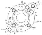
その結果、図5に示すように、補修弁Xから径外方向に膨出する複数の膨出部1b(本実施形態では、4箇所)が、周方向に形成されている。なお、本実施形態における埋込ボルト4は、六角穴を形成した円形状の頭部4aを有する六角穴付きボルトの例を示しているが、例えば、両ネジボルトをナットで締め付ける構成としても良く、特に限定されない。
As a result, as shown in FIG. 5, a plurality of bulging
図1〜図2に示すように、補修弁Xの一端には、シール部材21を介在させた状態で空気弁Lや消火栓などが取付けられ、補修弁Xの他端には、シール部材22を介在させた状態で水道管の分岐管Mなどが取付けられる。補修弁Xの一端には、円盤状のフランジ部1A(第二フランジ部の一例、以下「第二フランジ部1A」と称する。)が径外方向に突出形成され、この第二フランジ部1Aが、空気弁Lの端部から径外方向に突出した円盤状のフランジ部La(第一フランジ部の一例、以下「第一フランジ部La」と称する。)と連結ボルト7で接合される。一方、補修弁Xの他端には、円盤状のフランジ部1B(第一フランジ部の一例、以下「第一フランジ部1B」と称する。)が径外方向に突出形成され、この第一フランジ部1Bが、分岐管Mの端部から径外方向に突出した円盤状のフランジ部Ma(第二フランジ部の一例、以下「第二フランジ部Ma」と称する。)と連結ボルト7で接合される。
As shown in FIGS. 1 and 2, an air valve L and a fire hydrant are attached to one end of the repair valve X with a
補修弁Xの両フランジ部1A,1Bには、接合方向に貫通する複数の貫通孔1a,1a(本実施形態では、4箇所ずつ)が周方向で等間隔に形成され、空気弁Lの第一フランジ部Laや分岐管Mの第二フランジ部Maには、夫々、接合方向に貫通する複数の貫通孔2a,2b(本実施形態では、4箇所ずつ)が周方向で等間隔に形成されている。補修弁Xの両フランジ部1A,1Bの貫通孔1a,1aと空気弁Lの第一フランジ部Laや分岐管Mの第二フランジ部Maの貫通孔2a,2bとを重ね合わせた状態で、連結ボルト7を用いて接合される。なお、本実施形態では、4箇所の貫通孔に連結ボルト7を接合する例を示しているが、フランジ接合部の外径に応じて6箇所や8箇所等の貫通孔が形成されるものであり、特に限定されない。
A plurality of through
連結ボルト7は、第一連結ボルト7Aと第二連結ボルト7Bとで構成されている。第一連結ボルト7Aは、多角形状(本実施形態では六角形)の頭部71aおよび雄ねじ部を有するボルト部71と、多角形状(本実施形態では六角形)の第一ナット72とを備えている。また、第二連結ボルト7Bは、ボルト部71と、第一ナット72より嵩高い多角形状(本実施形態では六角形)の第二ナット73とを備えている。詳細は後述するが、連結ボルト7を挟んで補強治具Pを接合する箇所は、第二連結ボルト7Bを用いている。なお、第一連結ボルト7Aと第二連結ボルト7Bとは、夫々同じ規格で構成しても良いし、夫々のボルト部71を別規格で構成しても良い。また、ボルト部71の頭部71aやナット72,73を円形状に構成しても良いし、ボルト・ナット構造に代えて、埋込式のボルト構造にしても良く特に限定されない。
The connecting
以下、補修弁Xの両フランジ部1A,1Bにおいて、空気弁Lの第一フランジ部Laや分岐管Mの第二フランジ部Maに対向する接合面とは反対側で露出する面を外側面1c,1dとし、両フランジ部1A,1Bの径方向外側の面を外周面1e,1fとして説明する。同様に、空気弁Lの第一フランジ部Laにおいて、補修弁Xの第二フランジ部1Aに対向する接合面とは反対側で露出する面を外側面2c、径方向外側の面を外周面2eとし、分岐管Mの第二フランジ部Maにおいて、補修弁Xの第一フランジ部1Bに対向する接合面とは反対側で露出する面を外側面2d、径方向外側の面を外周面2fとして説明する。
Hereinafter, in both
[空気弁Lと補修弁Xとの接合部]
図2〜図4および図7〜図9を用いて、空気弁Lと補修弁Xとのフランジ接合部における補強治具Pについて説明する。ここで、空気弁Lと補修弁Xとの関係では、空気弁Lを第一筒状部材、補修弁Xを第二筒状部材として説明する。図2に示すように、補強治具Pは、第一フランジ部Laと第二フランジ部1Aとの接合部に装着される。
[Joint of air valve L and repair valve X]
The reinforcing jig P at the flange joint between the air valve L and the repair valve X will be described with reference to FIGS. 2 to 4 and FIGS. 7 to 9. Here, in the relationship between the air valve L and the repair valve X, the air valve L will be described as a first cylindrical member, and the repair valve X will be described as a second cylindrical member. As shown in FIG. 2, the reinforcing jig P is attached to a joint portion between the first flange portion La and the
図3〜図4に示すように、補強治具Pは、第二連結ボルト7Bの第二ナット73が配置される第一フランジ部Laの外側面2cにおいて、第二ナット73の両側領域を押圧する二つの押圧部6B,6B(第一押圧部の一例、以下「第一押圧部6B」と称する。)を備えた第一挟持部材6と、第二フランジ部1Aの外側面1cを押圧する二つの押圧部5C,5C(第二押圧部の一例、以下「第二押圧部5C」と称する。)を備えた第二挟持部材5と、を備えている。また、これら第一挟持部材6および第二挟持部材5を、両フランジ部La,1Aの接合方向に引き寄せて(近接させて)締付固定する締結機構8を備えている。これら押圧部6B,5Cの両フランジ部La,1Aに対向する押圧面6e,5eには、例えば、押圧面6e,5eに細かな凹凸を形成するなど、両フランジ部La,1Aの外側面2c,1cに対して摩擦抵抗が生じるように摩擦加工が施されていても良い。
As shown in FIGS. 3 to 4, the reinforcing jig P presses both side regions of the
図7に示すように、第一挟持部材6は、金属部材により構成され、被挿入部6Aと第一押圧部6Bとを一体的に備えている。被挿入部6Aは、横断面視(接合方向と垂直な断面視)において、外面6aおよび内面6bが第一フランジ部Laに近付くほど拡径する台形状を呈した有底角筒状で形成されている(図7(c)の底面視である図7(a)参照)。また、第一押圧部6Bは、被挿入部6Aの外面6aの四辺のうちの一辺から外方側に向かって二股状に延出して形成されている。
As shown in FIG. 7, the
被挿入部6Aの内部には、両フランジ部La,1Aの接合方向に沿って、後述する第二挟持部材5の挿入部5Aを受け入れる筒状内部空間6cが形成されている(図7(a)のVIIb−VIIb矢視図である図7(b)参照)。つまり、図9に示すように、補強治具Pが両フランジ部La,1Aに装着されるとき、第一フランジ部Laの外周面2eよりも径方向外側の位置において、第二挟持部材5に挿入部5Aが形成され、第一挟持部材6には、接合方向に沿って挿入部5Aを内部に受け入れる被挿入部6Aが形成されている。
A cylindrical
筒状内部空間6cは横断面視で台形状に形成され、台形状の挿入部5Aの外径よりも若干大きく形成されている。このため、図9に示すように、挿入部5Aの外面5aと被挿入部6Aの内面6bとの接合方向に垂直な断面形状は、挿入部5Aを被挿入部6Aの筒状内部空間6cに挿入すると、挿入方向(筒状内部空間6cの長手方向)には摺動可能であるが、挿入方向周り(筒状内部空間6cの長手方向に沿った軸周り)での相対回転が不能となるように形成されている。
The cylindrical
また、筒状内部空間6cにおいて、第一押圧部6Bが形成された側とは反対側が開口形成されている。筒状内部空間6cにおける第一押圧部6Bが形成された側は、締結ボルト8Aの雄ネジ部8aを挿入可能で且つ頭部8bを挿通不能な挿通孔6dが、被挿入部6Aの底部を貫通する状態で開口形成されている。なお、締結ボルト8Aの雄ネジ部8aが挿通孔6dに挿通された状態では、雄ネジ部8aの外周面と挿通孔6dの内周面との間には、所定の隙間が形成される(図2参照)。
In the cylindrical
第一押圧部6Bは、側面視で腕の長さが同一の二股状に形成され(図7(a)参照)、縦断面視で先端側に行くにつれて挿通孔6dから遠ざかるテーパー形状に形成されている(図7(b)参照)。また、第一押圧部6Bのうち筒状内部空間6cの開口側の先端部位が、被挿入部6Aの外面6aと垂直な押圧面6eとして形成されている。
The first
図3に示すように第一押圧部6Bは、第一フランジ部Laの外側面2cにおいて、空気弁Lの周方向に沿った第二ナット73の両側の領域を押圧するように構成されている。つまり、第一押圧部6Bは、被挿入部6Aの外面6aから外側に向かって第二ナット73の外径より大きな間隔を維持しつつ延出し、第二ナット73を収容するU字状のナット収容部6fを形成している。両挟持部材6,5を両フランジ部La,1Aに径外方向から装着すると、このナット収容部6fが第二ナット73に当接しない状態で、第一押圧部6Bが第一フランジ部Laの外側面2cを押圧することとなる。また、第一押圧部6Bの押圧面6eは、第一フランジ部Laと第二フランジ部1Aとの間に介在するシール部材21よりも径方向外側にある第二連結ボルト7Bの近傍を押圧することとなる。よって、シール部材21のシール機能を高めつつ、第二連結ボルト7Bの隙間から漏水することを確実に防止することができる。
As shown in FIG. 3, the first
第一挟持部材6の被挿入部6Aは、第一フランジ部Laの外周面2eおよび第二フランジ部1Aの外周面1eと対向する内表面(外面6a)の周方向に沿った両端部に、径内方向に突出して形成され、両フランジ部La,1Aに当接可能な当接部6hを有している(図7(c)参照)。この当接部6hは、第一フランジ部Laの外周面2eに対応した傾斜面を有している。詳細は後述するが、補強治具Pを締結機構8で固定する際、当接部6hが両フランジ部La,1Aに当接することで、補強治具Pの回転が阻止される。なお、この当接部6hは、第一フランジ部Laの外周面2eと対向する内表面のうち、補強治具Pが回転する方向の一方の端部にのみ設けても良い。また、当接部6hは、第一フランジ部Laの外周面2eまたは第二フランジ部1Aのいずれかの外周面2e,1eと対向する内表面にのみ設けても良い。さらに、当接部6hの形状も、複数の凸部で形成するなどどのような形状であっても良い。
The inserted
図8に示すように、第二挟持部材5は、金属部材により構成され、挿入部5Aと、挿入部5Aの外面5aから全周に亘って外方側に延出する鍔状部5Bと、鍔状部5Bの四辺のうちの一辺からさらに外方側に延出する第二押圧部5Cとを一体的に備えている。挿入部5Aは、横断面視において、外面5aが第二フランジ部1Aに近付くほど拡径する台形状を呈し、内面5bが円形状の有底角筒状で形成されている(図8(c)の平面視である図8(a)参照)。
As shown in FIG. 8, the
挿入部5Aの内部には、締結ボルト8Aの雄ネジ部8aを挿通可能な円筒状の筒状内部空間5cが形成されている。筒状内部空間5cの内径は、締結ボルト8Aの雄ネジ部8aの外径よりも大径に形成されている。
A cylindrical cylindrical
鍔状部5Bは、接合方向と垂直な断面視で台形状に形成され、中央部に筒状内部空間5cが貫通形成されている(図8(a)参照)。
The bowl-shaped
筒状内部空間5cにおいて、鍔状部5Bおよび第二押圧部5Cが形成された側は開口形成され、鍔状部5Bおよび第二押圧部5Cが形成された側とは反対側は、締結ボルト8Aの雄ネジ部8aが螺合可能な雌ネジ部5dが、挿入部5Aの底部を貫通する状態で開口形成されている(図8(a)のVIIIb−VIIIb矢視図である図8(b)参照)。つまり、雌ネジ部5dは、挿入部5Aにおける筒状内部空間5cの内面5bにおいて、鍔状部5Bおよび第二押圧部5Cが形成された側とは反対側の端部に形成されている。
In the cylindrical
第二押圧部5Cは、側面視で腕の長さが同一の二股状に形成され(図8(a)参照)、縦断面視で先端側に行くにつれて雌ネジ部5d側に傾斜するテーパー形状に形成されている(図8(b)参照)。また、第二押圧部5Cのうち雌ネジ部5d側の面の先端部位が、挿入部5Aの外面5aと垂直な押圧面5eとして形成されている。
The second
図4に示すように第二押圧部5Cは、第二フランジ部1Aの外側面1cにおいて、補修弁Xの周方向に沿った第二連結ボルト7Bの頭部71aの両側の領域を押圧するように構成されている。また、多角形状に形成された頭部71aの対向する両辺に沿って接触する接触面5gが設けられている。両挟持部材6,5を両フランジ部La,1Aに挿入して締結機構8で固定する際、当接部6hが両フランジ部La,1Aに当接すれば両挟持部材6,5の回転が阻止される。加えて、第二押圧部5Cの接触面5gを頭部71aの両辺に接触させることで、第二連結ボルト7Bの締結力が作用して両挟持部材6,5の回転を確実に阻止することができる。なお、本実施形態では、接触面5gを頭部71aの対向する両辺に沿って接触させているが、少なくとも頭部71aの一辺に対向する面が、頭部71aの一辺に近接した非接触状態で並行に形成されていれば良い。
As shown in FIG. 4, the second
また、図4に示すように、第二連結ボルト7Bの頭部71aと第二フランジ部1Aの外側面1cとの間にワッシャ部材71cが介在しており、第二押圧部5Cには、このワッシャ部材71cを収容する収容部5hが切欠き形成されている(図8(c)参照)。その結果、第二挟持部材5は、第二フランジ部1Aに対してワッシャ部材71cに邪魔されることなく挿入され、第二連結ボルト7Bの頭部71aの対向する両辺が接触面5gと接触した状態で、第一押圧部6Bが第二フランジ部1Aの外側面1cを押圧することとなる。なお、本実施形態では、第一連結ボルト7Aの頭部71aやナット72,73と両フランジ部La,1Aの外側面2c,1cとの間にもワッシャ部材71cが介在している。
Further, as shown in FIG. 4, a
締結機構8は、図9に示すように、被挿入部6Aの外側から挿通孔6dを介して筒状内部空間6c内に挿入される上述の締結ボルト8Aと、挿入部5Aの内面5bに形成された雌ネジ部5dとから構成されている。締結ボルト8Aは、雄ネジ部8aと、多角形状(本実施形態では六角形)の頭部8bと、を有している。なお、締結ボルト8Aは、六角ボルトに限定されず、六角穴付きボルト等どのような形態であっても良い。
As shown in FIG. 9, the
次に、両フランジ部La,1Aの接合部に、補強治具Pを装着する作業工程について説明する。 Next, an operation process for attaching the reinforcing jig P to the joint portion between both flange portions La and 1A will be described.
図9に示すように、まず、両フランジ部La,1Aの接合部にある複数の既設ボルト(不図示)を取外し、第一連結ボルト7Aや第二連結ボルト7Bに交換して仮締めする。次いで、両フランジ部La,1Aの外周面2e,1eよりも径方向外側の位置で、第二挟持部材5の挿入部5Aを、第一挟持部材6の被挿入部6Aの筒状内部空間6cに、接合方向に沿って挿入する。その際、挿入部5Aの外面5aと被挿入部6Aの内面6bとが横断面視で相対回転不能な台形状に形成されているので、第二挟持部材5の第二押圧部5Cと第一挟持部材6の第一押圧部6Bとを同方向に延出させた所望の相対位置関係に位置決めした状態で、容易に挿入することができる。
As shown in FIG. 9, first, a plurality of existing bolts (not shown) at the joint between both flange portions La and 1A are removed, replaced with the
次いで、締結ボルト8Aを、接合方向における被挿入部6Aの外側から挿通孔6dを介して筒状内部空間6c内に挿入し、仮固定する。これら挿入部5Aと被挿入部6Aとの係合および締結ボルト8Aの仮固定は、第一押圧部6Bの押圧面6eと第二押圧部5Cの押圧面5eとの間隔が、第一フランジ部Laの外側面2cと第二フランジ部1Aの外側面1cとの間隔よりも若干大きくなる程度に行われる。つまり、接合方向における挿入部5Aと被挿入部6Aとの重なり部位の大きさ(挿入距離)、および、押圧面5eと押圧面6eとの間隔をそれぞれ適宜設定することができる。このため、両フランジ部La,1Aの呼び径や設計圧力に応じて肉厚が変更される場合でも、重なり部位の大きさを調整することで、両挟持部材6,5を両フランジ部La,1Aに良好に締付固定することができる。
Next, the
続いて、両挟持部材6,5の押圧部6B,5Cが第二連結ボルト7Bの両側に位置するように補強治具Pを両フランジ部La,1Aに径外方向から挿入しつつ、被挿入部6Aの外面6aを両フランジ部La,1Aの外周面2e,1eの少なくとも一方に当接させる。この状態で、第一押圧部6Bの押圧面6eを第一フランジ部Laの外側面2cに当接させ、且つ、第二押圧部5Cの押圧面5eを第二フランジ部1Aの外側面1cに当接させるまで、挿入部5Aおよび被挿入部6Aを接合方向に引き寄せる。このとき、接触面5gが第二連結ボルト7Bの頭部71aの両辺に接触し、ワッシャ部材71cが収容部5hに収容された状態となる。
Subsequently, the reinforcing jig P is inserted into both flange portions La and 1A from the radially outward direction so that the
次いで、締結ボルト8Aを締付けて本固定する。このとき、締結ボルト8Aは、両フランジ部La,1Aより径方向外側の位置にあるため、締付作業が容易である。一方、締結ボルト8Aの締付作業に伴って、両挟持部材6,5が両フランジ部La,1Aに対して相対回転して、両挟持部材6,5が脱落するおそれがある。
Next, the
しかしながら、本実施形態における補強治具Pは、両フランジ部La,1Aの外周面2e,1eに対向する外面6aの端部に当接部6hを有するので、当接部6hが両フランジ部La,1Aに当接して両挟持部材6,5の回転を阻止することができる。しかも、第二押圧部5Cの接触面5gが頭部71aの両辺に接触しているので、第二連結ボルト7Bの締結力が作用して両挟持部材6,5の回転を未然に阻止することができる。その結果、締結ボルト8Aの締付作業がより一層容易なものとなり、両挟持部材6,5の装着姿勢を安定させることができる。なお、上述した締結ボルト8Aの仮固定を行わずに、本固定のみとしても良い。
However, since the reinforcing jig P in the present embodiment has the
一つの補強治具Pが両フランジ部La,1Aに本固定されると、他の補強治具Pも同様の作業を繰り返して本固定する。そして、両フランジ部La,1Aの外側面2c,1cに対向して配置される第二連結ボルト7Bの2箇所に補強治具Pを本固定した後、全ての第一連結ボルト7Aおよび第二連結ボルト7Bを本固定して、補強治具Pの装着が完了する。このとき、第二連結ボルト7Bを高ナット式で構成しているので、締付作業が容易である。また、第二押圧部5Cの接触面5gが第二連結ボルト7Bの頭部71aに当接するので、第二ナット73のみを締め付ければボルト部71の共回りが防止され、締付作業が効率的である。なお、補強治具Pの本固定や第一連結ボルト7Aおよび第二連結ボルト7Bの本固定は、適宜順番を入れ替えても良いし、繰り返し実施しても良い。また、本実施形態では、4箇所の連結ボルト7のうちの2箇所に補強治具Pを装着する例を示したが、接合部の必要強度に応じて1箇所や3箇所以上の連結ボルト7に補強治具Pを装着しても良い。
When one reinforcing jig P is permanently fixed to both flange portions La and 1A, the other reinforcing jigs P are fixed by repeating the same operation. And after fixing the reinforcement jig | tool P to two places of the
このように、両挟持部材6,5の押圧部6B,5Cを両フランジ部La,1Aの外側面2c,1cに当接させた状態で、挿入部5Aが被挿入部6Aの内部に固定され、挿入部5Aと被挿入部6Aとが接合方向で重なった状態となる。このため、両フランジ部La,1Aを径方向に位置ズレさせる剪断力が作用した場合や、両フランジ部La,1Aを軸方向に引き離す引張力が作用して押圧部6B,5Cが開き方向の力を受けた場合でも、締結機構8の締結部位に加えて、挿入部5Aと被挿入部6Aとの重なり部位でもこれらの力を受け止めるので、締結機構8の締結部位に掛かる締結力が低下するのを防止することができる。
In this way, the
また、挿入部5Aの雌ネジ部5dが、締結ボルト8Aの頭部8bに近接した位置に位置することから、雌ネジ部5dと締結ボルト8Aの雄ネジ部8aとの螺合箇所が、締結ボルト8Aの頭部8bが被挿入部6Aの上面6gと当接する位置に近接する。つまり、接合方向における締結ボルト8Aの頭部8bと当該螺合箇所との距離が比較的小さい。これにより、両フランジ部La,1Aに剪断力や引張力が作用した場合でも、締結ボルト8Aの伸びや破壊を良好に防止することができる。
Further, since the
また、雌ネジ部5dを、筒状内部空間6c内における挿入部5Aと被挿入部6Aとの重なり部位に位置させているので、締結ボルト8Aの長さを比較的短くすることが可能となる。しかも、本実施形態では、両フランジ部La,1Aの外周面2e,1eの径方向外側位置において、挿入部5Aおよび被挿入部6Aの配設箇所と、締結ボルト8Aの配設箇所とが同じになる。これにより、両フランジ部La,1Aに装着された補強治具Pおよび締結ボルト8Aの接合方向での寸法や径方向での寸法の何れをも小さくすることができ、省スペース化を図ることができる。
Further, since the
このように、補強治具Pを装着することで、両フランジ部La,1Aの接合部を確実に補強することができる。このとき、第一挟持部材6や第二挟持部材5に二股状の第一押圧部6Bや第二押圧部5Cを設けることで、両フランジ部La,1Aの外側面2c,1cのうち連結ボルト7より径内側部位の空間が狭隘な場合でも、補強治具Pを径外方向から容易に装着することができる。しかも、被挿入部6Aの内面6bおよび挿入部5Aの外面5aが、第二フランジ部1Aに近付くほど拡径する台形状に形成されているので、押圧部6B,5Cの押圧面積を広く確保することができる。その結果、補修弁Xのフランジ接合部の補強強度が、効果的に高められる。
In this way, by attaching the reinforcing jig P, it is possible to reliably reinforce the joint between the flange portions La and 1A. At this time, the
[補修弁Xと分岐管Mとの接合部]
図5〜図6および図10には、補修弁Xと分岐管Mとの接合部に、補強治具Pを装着する実施形態が示される。なお、上述した空気弁Lと補修弁Xとの接合部に補強治具Pを装着する実施形態とは異なる構成のみ説明する。ここで、補修弁Xと分岐管Mとの関係では、補修弁Xを第一筒状部材、分岐管Mを第二筒状部材として説明する。
[Joint of repair valve X and branch pipe M]
5 to 6 and 10 show an embodiment in which a reinforcing jig P is attached to the joint between the repair valve X and the branch pipe M. Only the configuration different from the embodiment in which the reinforcing jig P is attached to the joint between the air valve L and the repair valve X described above will be described. Here, regarding the relationship between the repair valve X and the branch pipe M, the repair valve X will be described as a first cylindrical member, and the branch pipe M will be described as a second cylindrical member.
上述した空気弁Lと補修弁Xとの接合部に、所定の間隔(例えば接合面間隔が100mm〜400mm)空けて、補修弁Xと分岐管Mとの接合部が形成されている。図3,図5に示すように、この接合部に装着される補強治具Pは、空気弁Lと補修弁Xとの接合部に装着される補強治具Pに対して周方向の位置を約45度ずらして配置している。つまり、補修弁Xで規定される接合面間隔が小さい場合でも、上下に配置される補強治具Pが互いに干渉しないので、あらゆる接合面間隔を有するフランジ接合部を補強することが可能となる。なお、上下方向の各補強治具Pの周方向の位置を約45度ずらして配置することに限定されず、例えば30度ずらして配置しても良く、どのような角度であっても良いし、上下方向の各補強治具Pの周方向の位置をずらさなくても良い。 A joint portion between the repair valve X and the branch pipe M is formed in the joint portion between the air valve L and the repair valve X described above with a predetermined interval (for example, a joint surface interval of 100 mm to 400 mm). As shown in FIGS. 3 and 5, the reinforcing jig P attached to the joint portion is positioned in the circumferential direction with respect to the reinforcing jig P attached to the joint portion between the air valve L and the repair valve X. It is shifted about 45 degrees. That is, even when the joint surface interval defined by the repair valve X is small, the reinforcing jigs P arranged above and below do not interfere with each other, so that it is possible to reinforce the flange joint portion having any joint surface interval. It should be noted that the circumferential positions of the reinforcing jigs P in the vertical direction are not limited to be shifted by about 45 degrees, and may be shifted by, for example, 30 degrees or any angle. The circumferential position of each reinforcing jig P in the vertical direction need not be shifted.
ところで、近年の浅埋設用の補修弁Xは、特に接合面間隔が狭い。この場合、補修弁Xと分岐管Mとの接合部に固定される補強治具Pの締結ボルト8Aの頭部8bを、第二フランジ部Maの外側面2d側に配置するのが好ましい。つまり、図2に示す補修弁Xと分岐管Mとの接合部に固定される補強治具Pを上下逆向きに設置することで、締結機構8の頭部8bが接合面間隔の空間を占有しないので、補強治具Pどうしの干渉を防止することができる。その結果、上下方向の各補強治具Pの周方向の位置をずらす必要がなくなると共に、締結機構8の本固定や、連結ボルト7の本固定を、第二フランジ部Maの外側面2d側から作業できるので、効率的である。
By the way, the recent repair valve X for embedding has a particularly narrow joint surface interval. In this case, it is preferable to arrange the
図5に示すような接合方向視において、補修弁Xと分岐管Mとの接合部には、補修弁Xの筒本体から径外方向に膨出する複数の膨出部1bが周方向に配置されている。また、各膨出部1bの間には、複数の第一連結ボルト7Aが配置されている。このため、第一連結ボルト7Aと膨出部1bとの周方向の間隔が狭く、該間隔に補強治具Pを挿入することが困難である。そこで、本実施形態では、第一挟持部材6の第一押圧部6Bが、膨出部1bの周方向に沿った両側の領域を押圧する構成としている。その結果、補強治具Pを両フランジ部1B,Maの径外方向から挿入した際、第一押圧部6Bを十分に挿入することができる。
In the joining direction view as shown in FIG. 5, a plurality of bulging
また、本実施形態では、図6に示すように、連結ボルト7の配置されない部位に第二挟持部材5の第二押圧部5Cが配置されている。つまり、補修弁Xと分岐管Mとの接合部に用いられる補強治具Pと同様の補強治具Pを使用することで、量産化を図って製造コストを節約している。なお、本実施形態では、補強治具Pを連結ボルト7の存在しない部位に装着するので、第二挟持部材5に二股状の第二押圧部5Cを形成せずに、単一の第二押圧部5Cで構成しても良い。
Moreover, in this embodiment, as shown in FIG. 6, the
次に、補強治具Pを装着する作業工程について、図10を用いて簡単に説明する。まず、両フランジ部1B,Maの接合部にある複数の既設ボルト(不図示)を取外し、第一連結ボルト7Aに交換して仮締めする。次いで、両フランジ部1B,Maの外周面1f,2fよりも径方向外側の位置で、挿入部5Aを、被挿入部6Aの筒状内部空間6cに接合方向に沿って挿入する。次いで、締結ボルト8Aを、接合方向における被挿入部6Aの外側から挿通孔6dを介して筒状内部空間6c内に挿入し、仮固定する。
Next, an operation process for mounting the reinforcing jig P will be briefly described with reference to FIG. First, a plurality of existing bolts (not shown) at the joint between the
続いて、膨出部1bの両側に第一押圧部6Bが位置するように補強治具Pを両フランジ部1B,Maに径外方向から挿入しつつ、被挿入部6Aの外面6aを両フランジ部1B,Maの外周面1f,2fの少なくとも一方に当接させる。次いで、締結ボルト8Aの雄ネジ部8aを、筒状内部空間6cに挿入されている挿入部5Aの雌ネジ部5dに螺合させて、締結ボルト8Aの頭部8bが被挿入部6Aの上面6gに当接するまで、本固定する。このとき、本実施形態においても、第一挟持部材6のうち、両フランジ部1B,Maの外周面1f,2fに対向する外面6aの端部に当接部6hを設けることで、両挟持部材6,5の回転を阻止することができる。なお、二つの第一押圧部6Bに挟まれるU字状の内周面(ナット収容部6f)を膨出部1bの外周形状に沿う形状に構成して、第一押圧部6Bの内周面を膨出部1bに当接する当接部6hとしても良い。この場合、第一挟持部材6の端部に設ける当接部6hを省略しても良く、両挟持部材6,5の回転を阻止することが可能である。
Subsequently, the reinforcing jig P is inserted into both
一つの補強治具Pが両フランジ部1B,Maに本固定されると、他の補強治具Pも同様の作業を繰り返して本固定する。そして、両フランジ部1B,Maの外側面1d,2dの周方向に対向して配置される膨出部1bの2箇所に補強治具Pを本固定した後、全ての第一連結ボルト7Aを本固定して、補強治具Pの装着が完了する。なお、本実施形態における作用効果は、上述した実施形態と同様であるので詳細な説明は省略する。
When one reinforcing jig P is permanently fixed to both the
以下、本発明に係る別実施形態について、上述した実施形態と異なる構成のみ、図11〜図12を用いて説明する。なお、図面の理解を容易にするため、同じ部材には同じ名称および符号を用いて説明する。 In the following, another embodiment according to the present invention will be described with reference to FIGS. In addition, in order to make an understanding of drawing easy, it demonstrates using the same name and code | symbol to the same member.
[別実施形態1]
図11に示すように、本実施形態では、第一挟持部材6のフランジ接合部とは反対側の外表面(外面6a)に多角形状の突起61を設けている。両挟持部材6,5をフランジ接合部に挿入して締結機構8で本固定する際、例えばレンチ(不図示)で突起61を挟持しつつ締結機構8の締結ボルト8Aを締付ければ、補強治具Pの回転を阻止することができる。なお、この突起61は、締結ボルト8Aの締付回転方向に対して奥側に位置する側面に設けても良く、レンチ等で挟持できる位置であれば特に限定されない。また、突起61は多角形状に限定されず、円形状などどのような形状であっても良い。
[Another embodiment 1]
As shown in FIG. 11, in this embodiment, the
[別実施形態2]
図12に示すように、本実施形態では、第一挟持部材6のフランジ接合部とは反対側の外表面に、中央に溝部62aを形成した多角形状の突起62を設けている。フランジ接合部に挿入された複数の補強治具Pを締結機構8で仮固定した後、夫々の補強治具Pに亘ってチェーンなどで構成される保持部材63を溝部62aに係入し、操作具64で保持部材63を手繰り寄せることで補強治具Pを径内方向に押圧する。次いで、両挟持部材6,5を締結機構8で本固定すれば、補強治具Pの回転を阻止することができる。次いで、保持部材63を取外せば、複数の補強治具Pは、フランジ接合部に対して所望の姿勢で配置される。なお、この保持部材63を取外さずに設置した状態としても良い。この場合、補強治具Pの固定姿勢を長期に亘って維持することができる。
[Another embodiment 2]
As shown in FIG. 12, in the present embodiment, a
[その他の実施形態]
(1)上述した実施形態では、第一挟持部材6は、被挿入部6Aと第一押圧部6Bとを一体的に構成したが、被挿入部6Aと第一押圧部6Bとを別部材で構成しても良い。この場合、第一押圧部6Bを雌ねじ部を有する可動部材で構成し、例えばボルトを螺合することで第一押圧部6Bを直動させて、フランジ接合部に両挟持部材6,5を近接させて固定する形態などが想定される。また、第一押圧部6Bをくさび部材などで移動させても良く、フランジ接合部に両挟持部材6,5を近接させて固定する方法はどのような形態であっても良い。また、第二挟持部材5の第二押圧部5Cを可動部材で構成しても良い。
[Other Embodiments]
(1) In the above-described embodiment, the
(2)両挟持部材6,5を締結機構8で本固定する際、補強治具Pの回転を阻止する形態として、押圧面6e,5eの表面にゴム部材を張り付けて、所望の摩擦抵抗を生じさせる構成としても良い。この場合、補強治具Pの回転を阻止しつつ、ゴム部材が押し潰されて両挟持部材6,5のフランジ接合部に対する密着性を高めることができる。
(2) When the both clamping
(3)フランジ接合部に装着された複数の両挟持部材6,5の径外方向への移動を規制するバンド部材を、複数の補強治具Pに亘って設けても良い。このバンド部材は、第一挟持部材6の上面6gに締結ボルト8Aを収容する貫通孔を形成した平板円環状に構成しても良いし、第一挟持部材6の上面6gとフランジ接合部とは反対側の外表面とに亘って断面視L字状の半環状部材をボルトで結合する構成としても良く、種々の形態が想定される。
(3) You may provide the band member which controls the movement to the radial direction of both the
(4)上述した実施形態における第一挟持部材6、第二挟持部材5、および締結機構8の構成は、適宜変更することができる。例えば、第二挟持部材5に挿入部5Aを設け、第一挟持部材6に被挿入部6Aを設けるように構成したが、第二挟持部材5に被挿入部を設け、第一挟持部材6に挿入部を設ける構成としても良い。この場合、第二挟持部材5は、フランジ接合部の外周面と対向する内表面の周方向に沿った端部に、径内方向に突出して形成される当接部6hが形成される。また、第二挟持部材5の挿入部5Aと第一挟持部材6の被挿入部6Aとの形状を横断面視において台形状としたが、横断面視で楕円形状や矩形状など、挿入部5Aと被挿入部6Aとが挿入された状態で接合方向周りでの相対回転が不能に構成されていればどのような形状であっても良い。また、第一押圧部6Bの形状と第二押圧部5Cの形状とを同一形状にしても良い。また、締結機構8をボルト・ナット構造にしても良く、特に限定されない。
(4) The structure of the
(5)上述した実施形態におけるフランジ接合部を連結する連結ボルト7は、六角ボルトに限定されず、両ネジボルトや六角穴付きボルト等どのような形態であっても良い。
(5) The connecting
(6)上述した実施形態では、補修弁Xと空気弁Lや分岐管Mとのフランジ接合部に補強治具Pを固定する例を示したが、流体機器どうしや配管どうしのフランジ接合部などに補強治具Pを用いることができることは勿論である。また、上述した補修弁Xは一例にすぎず、上述した実施形態における補強治具Pは様々な補修弁Xに対応することができる。 (6) In the above-described embodiment, the example in which the reinforcing jig P is fixed to the flange joint portion between the repair valve X, the air valve L, and the branch pipe M is shown. However, the flange joint portion between the fluid devices or between the pipes, etc. Of course, the reinforcing jig P can be used. Moreover, the repair valve X mentioned above is only an example, and the reinforcing jig P in the embodiment described above can correspond to various repair valves X.
本発明に係る接合部の補強治具は、流体機器内、流体機器と配管、流体機器どうし又は配管どうしの接合部を補強するための治具として利用可能である。 The joint reinforcing jig according to the present invention can be used as a jig for reinforcing a joint between a fluid device, a fluid device and a pipe, a fluid device, or a pipe.
1A 第二フランジ部
1B 第一フランジ部
1b 膨出部
1c,1d,2c,2d 外側面
1e,1f,2e,2f 外周面
5 第二挟持部材
5A 挿入部
5C 第二押圧部
5h 収容部
6 第一挟持部材
6A 被挿入部
6B 第一押圧部
6h 当接部
7 連結ボルト
71a 頭部
71c ワッシャ部材
73 ナット
8 締結機構
L 空気弁(第一筒状部材)
La 第一フランジ部
M 分岐管(第二筒状部材)
Ma 第二フランジ部
P 補強治具
X 補修弁(第一筒状部材または第二筒状部材)
1A
1e, 1f, 2e, 2f Outer
La 1st flange part M Branch pipe (2nd cylindrical member)
Ma 2nd flange part P Reinforcement jig X Repair valve (1st cylindrical member or 2nd cylindrical member)
Claims (5)
前記連結ボルトの頭部またはナット、もしくは前記第一筒状部材から径外方向に膨出する膨出部が配置される前記第一フランジ部の外側面を押圧する第一挟持部材と、
前記第二フランジ部の外側面を押圧する第二挟持部材と、
前記第一挟持部材と前記第二挟持部材とを、前記第一フランジ部および前記第二フランジ部の接合方向に近接させて固定する締結機構と、を備え、
前記第一挟持部材は、前記頭部または前記ナット、もしくは前記膨出部の前記第一筒状部材の周方向に沿った両側の領域を押圧する二つの第一押圧部を有し、
前記第一挟持部材または前記第二挟持部材には、前記第一筒状部材および前記第二筒状部材の少なくとも一方と当接可能な当接部が形成される接合部の補強治具。 Attached to the joint where the first flange part projecting radially outward from the end of the first cylindrical member and the second flange part projecting radially outward from the end of the second cylindrical member are joined with a connecting bolt And
A first clamping member that presses an outer surface of the first flange portion where a bulging portion that bulges radially outward from the head or nut of the connecting bolt or the first cylindrical member is disposed;
A second clamping member that presses the outer surface of the second flange portion;
A fastening mechanism for fixing the first clamping member and the second clamping member close to each other in the joining direction of the first flange portion and the second flange portion;
The first clamping member has two first pressing portions that press the regions on both sides along the circumferential direction of the first tubular member of the head or the nut or the bulging portion,
A joint reinforcing jig in which a contact portion capable of contacting at least one of the first tubular member and the second tubular member is formed on the first sandwiching member or the second sandwiching member.
前記二つの第二押圧部は、多角形状に形成された前記頭部または前記ナットの一辺に対向する面を、前記一辺に沿った形状に構成している請求項1又は2に記載の接合部の補強治具。 The second clamping member has two second pressing portions that press the regions on both sides along the circumferential direction of the head or nut of the connecting bolt disposed in the second flange portion,
The joint part according to claim 1 or 2, wherein the two second pressing portions are configured such that a surface facing one side of the head or the nut formed in a polygonal shape has a shape along the one side. Reinforcing jig.
前記締結機構は、前記挿入部と前記被挿入部とを前記接合方向に引き寄せて固定し、
前記挿入部と前記被挿入部とは、前記接合方向と垂直な断面が、前記第一フランジ部に近付くほど拡径する台形状に形成されている請求項1から4のいずれか一項に記載の接合部の補強治具。 An insertion portion is formed on either one of the first clamping member and the second clamping member at a position radially outward from the outer peripheral surface of the first flange portion, and the other is along the joining direction. An insertion portion for receiving the insertion portion therein is formed,
The fastening mechanism draws and fixes the insertion portion and the inserted portion in the joining direction,
The said insertion part and the said to-be-inserted part are formed in the trapezoid shape in which a cross section perpendicular | vertical to the said joining direction is diameter-expanded, so that it approaches the said 1st flange part. Reinforcing jig for joints.
Priority Applications (1)
| Application Number | Priority Date | Filing Date | Title |
|---|---|---|---|
| JP2015000260A JP6498938B2 (en) | 2015-01-05 | 2015-01-05 | Joining reinforcement jig |
Applications Claiming Priority (1)
| Application Number | Priority Date | Filing Date | Title |
|---|---|---|---|
| JP2015000260A JP6498938B2 (en) | 2015-01-05 | 2015-01-05 | Joining reinforcement jig |
Related Child Applications (1)
| Application Number | Title | Priority Date | Filing Date |
|---|---|---|---|
| JP2019046278A Division JP6747678B2 (en) | 2019-03-13 | 2019-03-13 | Joint reinforcement structure |
Publications (2)
| Publication Number | Publication Date |
|---|---|
| JP2016125599A true JP2016125599A (en) | 2016-07-11 |
| JP6498938B2 JP6498938B2 (en) | 2019-04-10 |
Family
ID=56359208
Family Applications (1)
| Application Number | Title | Priority Date | Filing Date |
|---|---|---|---|
| JP2015000260A Active JP6498938B2 (en) | 2015-01-05 | 2015-01-05 | Joining reinforcement jig |
Country Status (1)
| Country | Link |
|---|---|
| JP (1) | JP6498938B2 (en) |
Cited By (7)
| Publication number | Priority date | Publication date | Assignee | Title |
|---|---|---|---|---|
| JP2019032002A (en) * | 2017-08-04 | 2019-02-28 | 株式会社水道技術開発機構 | Fixing jig of valve case split portion and its mounting method |
| JP2019113155A (en) * | 2017-12-26 | 2019-07-11 | コスモ工機株式会社 | Flange separation prevention device |
| JP2020034042A (en) * | 2018-08-28 | 2020-03-05 | 岡山市 | Flange reinforcement jig and attachment method of the same |
| GB2585033A (en) * | 2019-06-25 | 2020-12-30 | Boltight Ltd | Hot bolting clamp |
| JP2021067306A (en) * | 2019-10-21 | 2021-04-30 | コスモ工機株式会社 | Flange reinforcing tool |
| JP2022008994A (en) * | 2017-12-26 | 2022-01-14 | コスモ工機株式会社 | Attachment method of flange separation prevention device |
| JP2022103207A (en) * | 2018-04-24 | 2022-07-07 | コスモ工機株式会社 | Mounting method for flange reinforcement tool |
Citations (8)
| Publication number | Priority date | Publication date | Assignee | Title |
|---|---|---|---|---|
| DE1196449B (en) * | 1960-12-29 | 1965-07-08 | Von Roll Ag | Clamp screw for connecting pipe flanges |
| JPH0653888U (en) * | 1992-12-28 | 1994-07-22 | 株式会社西原衛生工業所 | Pipe connection structure and pipe joint |
| JP2004316767A (en) * | 2003-04-16 | 2004-11-11 | Tokyo Gas Co Ltd | Flange connection part safety fixture, safety fixture for valve in pit, and safety method using these fixtures |
| JP2005147243A (en) * | 2003-11-14 | 2005-06-09 | Hitachi Metals Ltd | Flange joint body for valve pit |
| JP2005233210A (en) * | 2004-02-17 | 2005-09-02 | Cosmo Koki Co Ltd | Flange jointing device |
| JP2012036950A (en) * | 2010-08-05 | 2012-02-23 | Osaka Gas Co Ltd | Flange bolt part sealing implement and sealing method of flange coupling part using the same |
| JP2014062613A (en) * | 2012-09-21 | 2014-04-10 | Kyowa Kogyo Kk | Coupling structure of equipment for water service |
| JP2014141995A (en) * | 2013-01-22 | 2014-08-07 | Okayama City | Flange-connecting portion reinforcement fixture |
-
2015
- 2015-01-05 JP JP2015000260A patent/JP6498938B2/en active Active
Patent Citations (8)
| Publication number | Priority date | Publication date | Assignee | Title |
|---|---|---|---|---|
| DE1196449B (en) * | 1960-12-29 | 1965-07-08 | Von Roll Ag | Clamp screw for connecting pipe flanges |
| JPH0653888U (en) * | 1992-12-28 | 1994-07-22 | 株式会社西原衛生工業所 | Pipe connection structure and pipe joint |
| JP2004316767A (en) * | 2003-04-16 | 2004-11-11 | Tokyo Gas Co Ltd | Flange connection part safety fixture, safety fixture for valve in pit, and safety method using these fixtures |
| JP2005147243A (en) * | 2003-11-14 | 2005-06-09 | Hitachi Metals Ltd | Flange joint body for valve pit |
| JP2005233210A (en) * | 2004-02-17 | 2005-09-02 | Cosmo Koki Co Ltd | Flange jointing device |
| JP2012036950A (en) * | 2010-08-05 | 2012-02-23 | Osaka Gas Co Ltd | Flange bolt part sealing implement and sealing method of flange coupling part using the same |
| JP2014062613A (en) * | 2012-09-21 | 2014-04-10 | Kyowa Kogyo Kk | Coupling structure of equipment for water service |
| JP2014141995A (en) * | 2013-01-22 | 2014-08-07 | Okayama City | Flange-connecting portion reinforcement fixture |
Cited By (16)
| Publication number | Priority date | Publication date | Assignee | Title |
|---|---|---|---|---|
| JP2019032002A (en) * | 2017-08-04 | 2019-02-28 | 株式会社水道技術開発機構 | Fixing jig of valve case split portion and its mounting method |
| JP7411273B2 (en) | 2017-08-04 | 2024-01-11 | 株式会社水道技術開発機構 | How to install the fixing jig for the valve case split part |
| JP2022000596A (en) * | 2017-08-04 | 2022-01-04 | 株式会社水道技術開発機構 | Fixing jig of valve case split part and its attachment method |
| JP7008973B2 (en) | 2017-08-04 | 2022-01-25 | 株式会社水道技術開発機構 | Fixing jig for valve case division and its mounting method |
| JP7209390B2 (en) | 2017-08-04 | 2023-01-20 | 株式会社水道技術開発機構 | Fixture for valve case split and mounting method |
| JP2019113155A (en) * | 2017-12-26 | 2019-07-11 | コスモ工機株式会社 | Flange separation prevention device |
| JP2022008994A (en) * | 2017-12-26 | 2022-01-14 | コスモ工機株式会社 | Attachment method of flange separation prevention device |
| JP7161018B2 (en) | 2017-12-26 | 2022-10-25 | コスモ工機株式会社 | How to install the flange separation prevention device |
| JP7419431B2 (en) | 2018-04-24 | 2024-01-22 | コスモ工機株式会社 | How to install flange reinforcement |
| JP2022103207A (en) * | 2018-04-24 | 2022-07-07 | コスモ工機株式会社 | Mounting method for flange reinforcement tool |
| JP2020034042A (en) * | 2018-08-28 | 2020-03-05 | 岡山市 | Flange reinforcement jig and attachment method of the same |
| JP7142876B2 (en) | 2018-08-28 | 2022-09-28 | 岡山市 | Flange reinforcing jig and its mounting method |
| GB2585033B (en) * | 2019-06-25 | 2023-02-08 | Boltight Ltd | Hot bolting clamp |
| GB2585033A (en) * | 2019-06-25 | 2020-12-30 | Boltight Ltd | Hot bolting clamp |
| JP7330061B2 (en) | 2019-10-21 | 2023-08-21 | コスモ工機株式会社 | Flange stiffener |
| JP2021067306A (en) * | 2019-10-21 | 2021-04-30 | コスモ工機株式会社 | Flange reinforcing tool |
Also Published As
| Publication number | Publication date |
|---|---|
| JP6498938B2 (en) | 2019-04-10 |
Similar Documents
| Publication | Publication Date | Title |
|---|---|---|
| JP6498938B2 (en) | Joining reinforcement jig | |
| JP4830473B2 (en) | Fitting lock device | |
| JP6374250B2 (en) | Joining reinforcement jig | |
| JP2007078161A (en) | Housing type pipe joint | |
| KR101828502B1 (en) | Grooved joint adapter | |
| JP4897268B2 (en) | Detachment prevention structure for pipe joints and method for strengthening prevention of detachment of pipe joints | |
| US6641178B2 (en) | Jointing system for pipes | |
| JP4412589B2 (en) | Flange joining device | |
| JP2017145885A (en) | Reinforcement jig for junction and reinforcement structure for junction | |
| JP6747678B2 (en) | Joint reinforcement structure | |
| JP7123325B2 (en) | Joint reinforcement structure | |
| JP6910612B2 (en) | Joint reinforcement structure | |
| JP6262544B2 (en) | Flange joint reinforcing structure and annular protective member used therefor | |
| JP4871142B2 (en) | Detachment prevention structure of pipe joint part, locking part large diameter remodeling method of insertion pipe part and locking part large diameter remodeling tool for insertion pipe part | |
| JP7142876B2 (en) | Flange reinforcing jig and its mounting method | |
| JP6935888B2 (en) | How to install the reinforcement jig | |
| JP7216407B2 (en) | Pipe joint structure | |
| JP2001173853A (en) | Detachment preventive device for tube fitting part | |
| JP4987236B2 (en) | Housing type pipe fitting | |
| JP6995311B2 (en) | Joint reinforcement jig | |
| JP4711334B2 (en) | Co-rotation prevention structure | |
| JP4347149B2 (en) | Mechanical joint of a longitudinal connection device for piles with means for preventing looseness | |
| JP2671776B2 (en) | Butterfly valve fittings | |
| JP5595812B2 (en) | Wheel | |
| JP2000120968A (en) | Pipe coupling structure |
Legal Events
| Date | Code | Title | Description |
|---|---|---|---|
| A621 | Written request for application examination |
Free format text: JAPANESE INTERMEDIATE CODE: A621 Effective date: 20171201 |
|
| A977 | Report on retrieval |
Free format text: JAPANESE INTERMEDIATE CODE: A971007 Effective date: 20180831 |
|
| A131 | Notification of reasons for refusal |
Free format text: JAPANESE INTERMEDIATE CODE: A131 Effective date: 20180905 |
|
| A521 | Request for written amendment filed |
Free format text: JAPANESE INTERMEDIATE CODE: A523 Effective date: 20181025 |
|
| TRDD | Decision of grant or rejection written | ||
| A01 | Written decision to grant a patent or to grant a registration (utility model) |
Free format text: JAPANESE INTERMEDIATE CODE: A01 Effective date: 20190212 |
|
| A61 | First payment of annual fees (during grant procedure) |
Free format text: JAPANESE INTERMEDIATE CODE: A61 Effective date: 20190314 |
|
| R150 | Certificate of patent or registration of utility model |
Ref document number: 6498938 Country of ref document: JP Free format text: JAPANESE INTERMEDIATE CODE: R150 |
|
| R250 | Receipt of annual fees |
Free format text: JAPANESE INTERMEDIATE CODE: R250 |
|
| R250 | Receipt of annual fees |
Free format text: JAPANESE INTERMEDIATE CODE: R250 |
|
| R250 | Receipt of annual fees |
Free format text: JAPANESE INTERMEDIATE CODE: R250 |