JP2016123744A - Respiratory gas heating humidifier and jacket heater - Google Patents
Respiratory gas heating humidifier and jacket heater Download PDFInfo
- Publication number
- JP2016123744A JP2016123744A JP2015000787A JP2015000787A JP2016123744A JP 2016123744 A JP2016123744 A JP 2016123744A JP 2015000787 A JP2015000787 A JP 2015000787A JP 2015000787 A JP2015000787 A JP 2015000787A JP 2016123744 A JP2016123744 A JP 2016123744A
- Authority
- JP
- Japan
- Prior art keywords
- breathing gas
- heater
- heating
- jacket heater
- patient
- Prior art date
- Legal status (The legal status is an assumption and is not a legal conclusion. Google has not performed a legal analysis and makes no representation as to the accuracy of the status listed.)
- Pending
Links
Images
Landscapes
- Air Humidification (AREA)
Abstract
Description
本発明は、人工呼吸器や酸素吸入療法等に用いられる呼吸用ガスを適度の温度、湿度に維持するための加温加湿器及びこの加温加湿器に用いられるジャケットヒータに関する。 The present invention relates to a warming humidifier for maintaining a breathing gas used in a ventilator, oxygen inhalation therapy, and the like at an appropriate temperature and humidity, and a jacket heater used in the warming humidifier.
従来から、所定量の酸素を含んだ呼吸用ガスを患者の気道へ送る人工呼吸器や、酸素吸入療法のための装置が知られている。このような装置においては、患者に乾燥した呼吸用ガスが供給されると、患者に不快感を与えるだけではなく、気道の損傷をもたらすおそれがある。このため、従来から呼吸用ガスに水蒸気を取り込んで適度の温度、湿度に維持するための加温加湿器が用いられてきた。 2. Description of the Related Art Conventionally, a ventilator for sending a breathing gas containing a predetermined amount of oxygen to a patient's respiratory tract and a device for oxygen inhalation therapy are known. In such devices, when the patient is supplied with dry breathing gas, it not only makes the patient uncomfortable, but can also cause airway damage. For this reason, a warming humidifier for taking water vapor into the breathing gas and maintaining it at an appropriate temperature and humidity has been used.
また、このような加温加湿器においては、患者に装着されるカニューラやマスク等の患者インターフェースに加温加湿された呼吸用ガスが送気チューブを介して供給されることから、呼吸用ガスが送気チューブを通過する際に、室内の雰囲気により冷やされないように、送気チューブを加温することが行われている。
この場合、送気チューブ内部にヒータ線を配置する構造であると、ヒータ線と接触する部分と接触しない部分とで温度ムラが生じて結露が生じ易くなり、また、ヒータが何らかの原因でショート状態となった時に呼吸ガスが発火する懸念もあるので、送気チューブの外側にヒータを設けたものが提案されている。
In such a humidifier, since the breathing gas heated and humidified is supplied to the patient interface such as a cannula or mask attached to the patient via the air supply tube, the breathing gas is not supplied. When passing through the air supply tube, the air supply tube is heated so as not to be cooled by the indoor atmosphere.
In this case, if the heater wire is arranged inside the air supply tube, temperature unevenness is likely to occur between the portion in contact with the heater wire and the portion not in contact with the heater wire, and condensation tends to occur. Since there is a concern that the breathing gas may be ignited, the heater provided outside the air supply tube has been proposed.
特許文献1では、平滑な内面を有する内側チューブ(内管)とそれを覆う蛇管状の外管とからなる二層構造で、その内側チューブと外管との間にヒータ線(ワイヤ)を配設した送気チューブ(呼吸管)が開示されている。内側チューブと外管との二層構造であるために内側チューブは外管との間に形成される断熱層に囲まれ室内の雰囲気による影響が減少し、呼吸用ガスの温度低下や結露発生を防止する効果がある。また、ヒータ線が直接呼吸ガスに触れないことで呼吸ガスの発火リスクも減少する。 In Patent Document 1, a two-layer structure consisting of an inner tube (inner tube) having a smooth inner surface and a serpentine outer tube covering the inner tube is provided, and a heater wire (wire) is arranged between the inner tube and the outer tube. An installed air supply tube (respiratory tube) is disclosed. Due to the two-layer structure of the inner tube and outer tube, the inner tube is surrounded by a heat insulating layer formed between the outer tube and the influence of the indoor atmosphere is reduced, reducing the temperature of breathing gas and generating condensation. There is an effect to prevent. In addition, since the heater wire does not touch the breathing gas directly, the risk of ignition of the breathing gas is reduced.
ところで、呼吸用ガスを患者に送る内側チューブは、ディスポーザブル製品として取扱われ使用が終わると廃棄する必要がある。ここで、特許文献1に記載の送気チューブは、内側チューブとヒータ線と外管とが一体構造で形成されているので、呼吸用ガスとは隔離されており、本来廃棄する必要がない外管やヒータ線までも一体として廃棄することが必要となり、大変不経済である。 By the way, the inner tube that sends the breathing gas to the patient is handled as a disposable product and needs to be discarded after use. Here, since the inner tube, the heater wire, and the outer tube are formed as an integral structure, the air supply tube described in Patent Document 1 is isolated from the breathing gas and is not required to be discarded. Even pipes and heater wires need to be disposed of as one unit, which is very uneconomical.
本発明は、このような事情に鑑みてなされたもので、ディスポーザブル製品を最小限にした上で、室内の雰囲気による影響で結露を生じさせることなく十分な加温及び加湿がなされた呼吸用ガスを安定して患者に供給することが可能な呼吸用ガスの加温加湿器及びこの加温加湿器に用いられるジャケットヒータを提供することを目的とする。 The present invention has been made in view of such circumstances, and a respirable gas that has been sufficiently heated and humidified without causing condensation due to the influence of the indoor atmosphere while minimizing disposable products. An object of the present invention is to provide a breathing gas heating / humidifying device capable of stably supplying gas to a patient and a jacket heater used in the heating / humidifying device.
本発明の呼吸用ガスの加温加湿器は、呼吸用ガスを加温加湿する加温加湿器本体と、該加温加湿器本体と患者に装着される患者インターフェースとの間を接続して患者に呼吸用ガスを供給する送気チューブとを有し、該送気チューブは、呼吸用ガスの流通経路を形成する内側チューブと、該内側チューブの外周面を包囲する着脱可能なジャケットヒータとを有し、該ジャケットヒータは、柔軟性を有する面状ヒータと、該面状ヒータにより前記内側チューブの外周面を包囲したときに、その包囲状態を保持する留め具とを有している。 The respiratory gas warming humidifier of the present invention connects a warming humidifier body for warming and humidifying a breathing gas, and the warming humidifier body and a patient interface attached to a patient to connect a patient. An air supply tube that supplies a breathing gas to the inner tube, and the air supply tube includes an inner tube that forms a flow path for the breathing gas, and a removable jacket heater that surrounds the outer peripheral surface of the inner tube. The jacket heater includes a planar heater having flexibility, and a fastener that holds the surrounding state when the outer peripheral surface of the inner tube is enclosed by the planar heater.
この呼吸用ガスの加温加湿器は、送気チューブが内側チューブと着脱可能なジャケットヒータとで構成されているので、ディスポーザブル製品である内側チューブは使用後廃棄するものの、ジャケットヒータは再利用することができ経済的である。
また、着脱可能なジャケットヒータは柔軟な面状ヒータで形成されているので、内側チューブの外周面を隙間なく包囲して均一に加熱することができる。
This breathing gas warming humidifier is composed of an inner tube and a removable jacket heater, so the inner tube, which is a disposable product, is discarded after use, but the jacket heater is reused. Can be economical.
Moreover, since the detachable jacket heater is formed of a flexible planar heater, the outer peripheral surface of the inner tube can be surrounded without any gap and heated uniformly.
本発明の呼吸用ガスの加温加湿器において、前記ジャケットヒータは、前記面状ヒータの外周面を包囲する断熱層を有しているとよい。
このジャケットヒータは、面状ヒータの外周面を断熱層で包囲することで放熱を防ぎ、面状ヒータの熱を内側チューブに伝えて呼吸用ガスを効率的に加温することができる。
In the breathing gas heating humidifier of the present invention, the jacket heater may have a heat insulating layer surrounding an outer peripheral surface of the planar heater.
This jacket heater can prevent heat dissipation by surrounding the outer peripheral surface of the planar heater with a heat insulating layer, and can efficiently heat the breathing gas by transmitting the heat of the planar heater to the inner tube.
本発明の呼吸用ガスの加温加湿器において、前記留め具は、線ファスナー又は面ファスナーであるとよい。
ジャケットヒータの留め具を線ファスナー又は面ファスナーにすることで、ジャケットヒータを内側チューブの外周面に巻きつけ保持する作業が簡便となる。
In the breathing gas heating humidifier according to the present invention, the fastener may be a wire fastener or a hook-and-loop fastener.
By making the fastener of the jacket heater into a wire fastener or a hook-and-loop fastener, the work of winding and holding the jacket heater around the outer peripheral surface of the inner tube becomes simple.
また、本発明の呼吸用ガスの加温加湿器において、前記ジャケットヒータは、その両面が表面層に覆われており、該表面層は撥水性を有しているとよい。
表面層が撥水性を有しているので、水等が滴下される場合でも、内部に浸透することはなく安全である。
Moreover, in the respirator warming humidifier of the present invention, the jacket heater is preferably covered with a surface layer on both sides, and the surface layer preferably has water repellency.
Since the surface layer has water repellency, even when water or the like is dropped, it does not penetrate inside and is safe.
また、本発明は、呼吸用ガスを加温加湿する加温加湿器本体と患者に装着される患者インターフェースとの間を接続して患者に呼吸用ガスを供給する送気チューブの外周面を着脱可能に包囲し、前記呼吸用ガスを加温するためのジャケットヒータであって、柔軟性を有する面状ヒータと、該面状ヒータに積層された断熱層と、前記送気チューブを包囲したときに両端部を着脱可能に保持する留め具とを有することを特徴とする。 In addition, the present invention connects / disconnects the outer peripheral surface of an air supply tube that supplies a breathing gas to a patient by connecting between a heating / humidifying device body that heats and humidifies the breathing gas and a patient interface attached to the patient. A jacket heater for enveloping and heating the breathing gas, wherein a flexible planar heater, a heat insulating layer laminated on the planar heater, and the air supply tube are enclosed It has the fastener which hold | maintains both ends so that attachment or detachment is possible.
本発明の呼吸用ガスの加温加湿器によれば、ディスポーザブル製品である内側チューブは使用後廃棄するが、着脱可能なジャケットヒータは再利用でき経済的である。また、そのジャケットヒータは、面状ヒータよりなることで内側チューブを隙間なく包囲して均一に加熱でき、効率的である。 According to the humidifier / heater for breathing gas of the present invention, the inner tube which is a disposable product is discarded after use, but the removable jacket heater can be reused and economical. In addition, the jacket heater is efficient because it can be heated uniformly by surrounding the inner tube without any gap by being made of a planar heater.
以下、本発明に係る呼吸用ガスの加温加湿器の実施形態について、図面を参照しながら説明する。
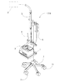
図2に示す本実施形態の呼吸用ガスの加温加湿器110は、例えば、自発呼吸を補助して呼吸障害を治療するためのCPAP装置等に接続されて用いられる。CPAP装置は、持続気道陽圧(CPAP:continuous positive airway pressure)と呼ばれる方式の補助喚起法を用いて患者に治療を施す装置であり、ネーザルプロング、気管挿管チューブ、鼻マスク等の患者インターフェース2を介して所定量の酸素と空気との混合気体からなる呼吸用ガスを患者に供給する。そして、呼吸用ガスの加温加湿器110は、患者に供給される呼吸用ガスを適度の温度及び湿度に維持するために設けられており、CPAP装置から送られる呼吸用ガスは呼吸用ガスの加温加湿器110で加温加湿され、患者に供給されるようになっている。
DESCRIPTION OF EMBODIMENTS Hereinafter, an embodiment of a respirating gas heating humidifier according to the present invention will be described with reference to the drawings.
The breathing
呼吸用ガスの加温加湿器110は、図2に示すように、制御部及びヒータ部等が内蔵された加温加湿器本体1と、加温加湿器本体1に着脱可能に設けられたチャンバ3とを備え、チャンバ3内に溜めた水をヒータで加熱しつつ内部空間に呼吸用ガスを通過させることにより、呼吸用ガスを加温加湿できるようになっている。また、チャンバ3には、呼吸用ガスを送り込む供給用ホース4と、加温加湿後の呼吸用ガスをチャンバ3から患者インターフェース2に送り出す送気チューブ5と、チャンバ3内に水を供給する給水部6とが接続されるようになっている。
なお、呼吸用ガスの加温加湿器110は、図2に示すように、キャスタ71により移動自在な架台7上に載置されており、架台7とともに全体を移動可能になっている。また、図示は省略するが、呼吸用ガスの加温加湿器110には、チャンバ3内に呼吸用ガスを送り込むためのガス供給機(例えば、CPAP装置)が接続される。
As shown in FIG. 2, the
As shown in FIG. 2, the breathing
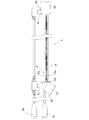
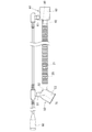
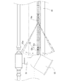
送気チューブ5は、図3に示すように呼吸用ガスの流通経路21を形成する内側チューブ20と、図1に示すように内側チューブ20を包囲して保温加熱するジャケットヒータ10とを有している。また、この送気チューブ5には、呼吸用ガスの温度を検出する温度センサ70,80が設けられている。
The
送気チューブ5の一方の端部には、図2に示すチャンバ3に接続するための入口側ソケット50が設けられ、他方の端部には患者インターフェース2に接続するための出口側ソケット60が設けられている。
入口側ソケット50は、チャンバ3に接続する接続口53と、温度センサ70を取付けるセンサ取付け口51と、内側チューブ20が接続される筒部52とを一体に形成した構成とされる。
出口側ソケット60は、患者インターフェース2に接続する接続口63と、温度センサ80を取付けるセンサ取付け口61と、内側チューブ20が接続される筒部62とを一体に形成した構成とされる。
An
The inlet-
The
入口側ソケット50の筒部52は接続口53に連通しており、センサ取付け口51は、接続口53に開口するように設けられている。
出口側ソケット60も入口側ソケット50の場合と同様であり、筒部62は接続口63に連通しており、センサ取付け口61は、接続口63に開口するように設けられている。
The
The
内側チューブ20は、一方の端部が入口側ソケット50の筒部52に接続され、他方の端部が出口側ソケット60の筒部62に接続され、呼吸用ガスの流通経路21を形成している。
内側チューブ20は、例えば、軟質な合成樹脂により形成されており、出口側ソケット60及び入口側ソケット50は、硬質な合成樹脂によって形成されている。
The
The
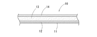
ジャケットヒータ10は、図4に示すように、ヒータ保護用の撥水加工された裏布11と、面状ヒータ12と、断熱層13と、撥水性素材よりなる表皮14とが積層された4層構造で構成されるとともに、各層は糸で縫い合わせることにより固定されており、展開したときには矩形の平面形状を有し、その幅方向の両端部を閉じて筒状に保持することができる留め具15が設けられている。内側チューブ20に巻き付ける際には、裏布11が内周面側になるように設けられる。また、面状ヒータ12には電源コードが接続され、その端部には、加温加湿器本体1へ接続するためのヒータ線接合コネクタ16が設けられている。
なお、裏布11及び表皮14は、異なる材質のもので構成してもよいし、同じ材質のもので構成してもよい。本発明においては、これら裏布11及び表皮14を表面層と称することとする。また、この表面層を撥水性素材により構成してもよいし、通常の布等の素材に撥水加工したものでもよく、本発明においては、これらを含めて「撥水性を有する」と定義している。
As shown in FIG. 4, the
The
このジャケットヒータ10は、内側チューブ20の外周部に巻きつけることができる幅と、内側チューブ20の全長を包囲する長さとを有している。また、この実施形態の場合、留め具15は線ファスナーによって構成されており、この線ファスナー(留め具15)は、各端部に設けられる一対の務歯15aと、その一対の務歯15aをかみ合わせ又は分離するスライダー15bとからなり、スライダー15bを移動させることにより務歯15a間を開閉する構成である。
そして、ジャケットヒータ10は、留め具15で幅方向の両端部を留めることで、全体として内側チューブ20の外周部を包囲する筒状に保持される。
The
And the
面状ヒータ12は、例えば、株式会社三機コンシス製の金属繊維ニットタイプの「マイルドウォーマー」や炭素繊維織物タイプの「マトリックスヒーター」などが用いられる。「マイルドウォーマー」は、銀の糸を編んだものがヒータとして使用され、その一方の面は発熱面であり、他方の面は通常の布であり、一方の面と他方の面とは絶縁がなされている。また「マトリックスヒーター」は、炭素繊維糸と銅電極糸の織物で構成されたヒータで、柔軟性と通気性とがよく、炭素繊維からなる発熱部分を銅繊維の電極でマトリックス状に囲っている。
断熱層13は、例えば、ネオプレンゴムスポンジなどが用いられる。
As the
For example, a neoprene rubber sponge is used for the
呼吸用ガスの温度を検出する温度センサ70,80は、チャンバ3から送り出された直後の呼吸用ガスの温度を検出する入口側温度センサ70と、患者インターフェース2への供給直前の呼吸用ガスの温度を検出する出口側温度センサ80とにより構成される。
入口側温度センサ70は入口側ソケット50のセンサ取付け口51から接続口53内に挿入され、出口側温度センサ80は出口側ソケット60のセンサ取付け口61から接続口63内に挿入されており、温度センサ接合コネクタ90を介して加温加湿器本体1に接続されている。
The
The inlet
加温加湿器本体1の制御部において、入口側温度センサ70(又は入口側温度センサ70に加えて出口側温度センサ80)の測定結果に基づいて加温加湿器本体1に内設されたヒータ部の発熱温度を制御し、入口側温度センサ70と出口側温度センサ80との測定温度差等により、ジャケットヒータ10の出力が制御される。
例えば、入口側温度センサ70の測定で呼吸ガスの温度が30℃〜37℃の範囲になるようにヒータ部の発熱温度を制御し、出口側温度センサ80の測定では入口側温度に対してプラス3℃となる、33℃〜40℃の範囲となるようにジャケットヒータ10の出力が制御される。
この入口側温度に対する出口側温度の制御は、送気チューブ5の長さに応じて固定の数値としてもよいし、使用者が変更可能とできるようにしてもよい。また、必ずしも出口側温度の方が入口側温度よりも高い温度となるような制御でなくてもよいし、その温度差も3℃には限らない。例えば、入口側温度が37℃で出口側温度が38℃、もしくは入口側温度が37℃で出口側温度が35℃等となるように使用者が変更可能としてもよい。ただし、入口側温度に対してプラス3℃を超える温度上昇は患者へ熱危害のおそれがあるため好ましくない。
なお、出口側温度センサ80には、温度センサ回路が二回線設けられており、どちらか一方が故障しても他方の温度センサ回路で測定が行える様に形成されている。
In the control unit of the warming humidifier body 1, a heater provided in the warming humidifier body 1 based on the measurement result of the inlet side temperature sensor 70 (or the outlet
For example, the heat generation temperature of the heater is controlled so that the temperature of the breathing gas is in the range of 30 ° C. to 37 ° C. as measured by the inlet
The control of the outlet side temperature with respect to the inlet side temperature may be a fixed numerical value according to the length of the
The outlet
内側チューブ20にジャケットヒータ10を装着するには、留め具15による固定を外してジャケットヒータ10を展開しておき、内側チューブ20の外周面にジャケットヒータ10を巻付け、留め具15(線ファスナー)のスライダー15bを移動しながらジャケットヒータ10の両端部に設けられている務歯15aどうしをかみ合わせることにより、ジャケットヒータ10を筒状に保持して内側チューブ20の外周面を包囲することができる。
このジャケットヒータ10を内側チューブ20に装着すると、ジャケットヒータ10の内径はほぼ内側チューブ20の外径となり、ジャケットヒータ10が柔軟性を有していることから、蛇腹状の内側チューブ20の外周面に密接して長手方向にずれにくくなる。また、図1に示すように、ジャケットヒータ10の両端が出口側ソケット60の筒部62の基端部分及び入口側ソケット50の筒部52の基端部分に当接することから、出口側ソケット60及び入口側ソケット50も実質的にストッパーとなって、ジャケットヒータ10の長手方向のずれを防止している。したがって、ジャケットヒータ10によって内側チューブ20の全長を包囲した状態に維持することができる。
In order to attach the
When this
本発明の呼吸用ガスの加温加湿器110は、送気チューブ5が内側チューブ20と着脱可能なジャケットヒータ10で構成されているので、ディスポーザブル製品である内側チューブ20は使用後廃棄するが、着脱可能なジャケットヒータ10は再利用でき経済的である。
また、ジャケットヒータ10で均一に加温及び保温することで、室内の雰囲気による影響で結露を生じさせることなく十分な加温及び加湿がなされた呼吸用ガスを安定して患者に供給することができる。
The breathing
Further, by uniformly warming and warming with the
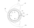
なお、第一実施形態では留め具15として線ファスナーを用いたが、図6に示すように面ファスナーとしてもよい。
図6に示す第二実施形態のジャケットヒータ30においては、留め具(面ファスナー)41は、相互に着脱可能な一対の接合半体41a,41bにより形成され、一方の接合半体41aはジャケットヒータ10の幅方向の一方の端部に接合面を外向きにして取付けられ、他方の接合半体41bはジャケットヒータ10の他方の端部に接合面を内向きに取付けられている。
また、ジャケットヒータ30の一方の端部の内周部には帯状片42が突出形成されており、ジャケットヒータ30を筒状に形成したときに、帯状片42が他方の端部の内周面に重ねられるようになっている。
In addition, although the wire fastener was used as the
In the
Further, a strip-
この第二実施形態のジャケットヒータ30を内側チューブ20に装着するには、ジャケットヒータ30を展開して内側チューブ20の外周面に巻付け、留め具41である面ファスナーの一方の接合半体41aの上に他方の接合半体41bを重ね合わせるようにして両接合半体41a,41bを接合することにより、全体を内側チューブ20に固定することができる。
この固定状態では、前述したように帯状片42が他方の端部に重ねられるので、その重ねられた部分では、ジャケットヒータ30の両端部の接合面が屈曲した状態となり、隙間から外気が進入することを確実に防止する効果がある。
In order to attach the
In this fixed state, as described above, the belt-
以上、本発明の実施形態について説明したが、本発明は、この実施形態に限定されるものではなく、特許請求の範囲に記載された発明の趣旨に基づいて各種の変更および修正が可能である。
例えば、実施形態では、留め具を線ファスナーや面ファスナーとして示したが、それらに限定するものではなく、ベルト状の物を巻きつけ、そのベルトで結び付ける等の構造としてもよい。
As mentioned above, although embodiment of this invention was described, this invention is not limited to this embodiment, Based on the meaning of the invention described in the claim, various changes and corrections are possible. .
For example, in the embodiment, the fastener is shown as a wire fastener or a hook-and-loop fastener, but the present invention is not limited thereto, and a structure in which a belt-like object is wound and tied by the belt may be used.
1 加温加湿器本体
2 患者インターフェース
3 チャンバ
4 供給用ホース
5 送気チューブ
10 ジャケットヒータ
11 裏布(表面層)
12 面状ヒータ
13 断熱層
14 表皮(表面層)
15 留め具
20 内側チューブ
21 呼吸用ガスの流通経路
30 ジャケットヒータ
41 留め具
110 呼吸用ガスの加温加湿器
DESCRIPTION OF SYMBOLS 1
12
DESCRIPTION OF
Claims (5)
柔軟性を有する面状ヒータと、該面状ヒータに積層された断熱層と、前記送気チューブを包囲したときに両端部を着脱可能に保持する留め具とを有することを特徴とするジャケットヒータ。
Removably surrounding an outer peripheral surface of an air supply tube that supplies a breathing gas to a patient by connecting between a humidifier body that heats and humidifies a breathing gas and a patient interface attached to the patient, A jacket heater for heating breathing gas,
A jacket heater, comprising: a planar heater having flexibility; a heat insulating layer laminated on the planar heater; and a fastener for detachably holding both ends when surrounding the air supply tube. .
Priority Applications (1)
| Application Number | Priority Date | Filing Date | Title |
|---|---|---|---|
| JP2015000787A JP2016123744A (en) | 2015-01-06 | 2015-01-06 | Respiratory gas heating humidifier and jacket heater |
Applications Claiming Priority (1)
| Application Number | Priority Date | Filing Date | Title |
|---|---|---|---|
| JP2015000787A JP2016123744A (en) | 2015-01-06 | 2015-01-06 | Respiratory gas heating humidifier and jacket heater |
Publications (1)
| Publication Number | Publication Date |
|---|---|
| JP2016123744A true JP2016123744A (en) | 2016-07-11 |
Family
ID=56358349
Family Applications (1)
| Application Number | Title | Priority Date | Filing Date |
|---|---|---|---|
| JP2015000787A Pending JP2016123744A (en) | 2015-01-06 | 2015-01-06 | Respiratory gas heating humidifier and jacket heater |
Country Status (1)
| Country | Link |
|---|---|
| JP (1) | JP2016123744A (en) |
Cited By (3)
| Publication number | Priority date | Publication date | Assignee | Title |
|---|---|---|---|---|
| CN113440712A (en) * | 2021-06-25 | 2021-09-28 | 宁波蓝野医疗器械有限公司 | Oxygen supply abnormity processing equipment for intensive care unit |
| KR102308562B1 (en) * | 2020-07-02 | 2021-10-05 | 주식회사 모건아이앤티 | Pipe insulation cover for semiconductor equipment |
| KR102751313B1 (en) * | 2023-10-18 | 2025-01-10 | (주)엔피코리아 | Insulating jacket for gas pipe heaters that is easy to install |
Citations (10)
| Publication number | Priority date | Publication date | Assignee | Title |
|---|---|---|---|---|
| JPS51113841U (en) * | 1975-03-12 | 1976-09-16 | ||
| JPS54149952A (en) * | 1978-05-17 | 1979-11-24 | Isago Miura | Tapeelike resistance heating unit |
| JP2001110555A (en) * | 1999-10-08 | 2001-04-20 | Showa Electric Wire & Cable Co Ltd | Mesh heater |
| JP2004185910A (en) * | 2002-12-02 | 2004-07-02 | Mitsui Kozan Material Kk | Electrothermal heater |
| JP2008183413A (en) * | 2000-03-21 | 2008-08-14 | Fisher & Paykel Healthcare Ltd | Humidifier |
| US20080279540A1 (en) * | 2007-05-11 | 2008-11-13 | Chao-Chih Huang | Air delivery pipe of a humidifying apparatus |
| JP3171497U (en) * | 2011-08-23 | 2011-11-04 | 株式会社三機コンシス | Sheet heater and clothing |
| WO2012077648A1 (en) * | 2010-12-06 | 2012-06-14 | ニチアス株式会社 | Jacket heater and heating method using jacket heater |
| JP2012165848A (en) * | 2011-02-14 | 2012-09-06 | Pacific Medico Co Ltd | Heating and humidifying device for artificial respirator |
| JP2014157824A (en) * | 2011-12-09 | 2014-08-28 | Sanki Consys Co Ltd | Cloth heater |
-
2015
- 2015-01-06 JP JP2015000787A patent/JP2016123744A/en active Pending
Patent Citations (10)
| Publication number | Priority date | Publication date | Assignee | Title |
|---|---|---|---|---|
| JPS51113841U (en) * | 1975-03-12 | 1976-09-16 | ||
| JPS54149952A (en) * | 1978-05-17 | 1979-11-24 | Isago Miura | Tapeelike resistance heating unit |
| JP2001110555A (en) * | 1999-10-08 | 2001-04-20 | Showa Electric Wire & Cable Co Ltd | Mesh heater |
| JP2008183413A (en) * | 2000-03-21 | 2008-08-14 | Fisher & Paykel Healthcare Ltd | Humidifier |
| JP2004185910A (en) * | 2002-12-02 | 2004-07-02 | Mitsui Kozan Material Kk | Electrothermal heater |
| US20080279540A1 (en) * | 2007-05-11 | 2008-11-13 | Chao-Chih Huang | Air delivery pipe of a humidifying apparatus |
| WO2012077648A1 (en) * | 2010-12-06 | 2012-06-14 | ニチアス株式会社 | Jacket heater and heating method using jacket heater |
| JP2012165848A (en) * | 2011-02-14 | 2012-09-06 | Pacific Medico Co Ltd | Heating and humidifying device for artificial respirator |
| JP3171497U (en) * | 2011-08-23 | 2011-11-04 | 株式会社三機コンシス | Sheet heater and clothing |
| JP2014157824A (en) * | 2011-12-09 | 2014-08-28 | Sanki Consys Co Ltd | Cloth heater |
Cited By (3)
| Publication number | Priority date | Publication date | Assignee | Title |
|---|---|---|---|---|
| KR102308562B1 (en) * | 2020-07-02 | 2021-10-05 | 주식회사 모건아이앤티 | Pipe insulation cover for semiconductor equipment |
| CN113440712A (en) * | 2021-06-25 | 2021-09-28 | 宁波蓝野医疗器械有限公司 | Oxygen supply abnormity processing equipment for intensive care unit |
| KR102751313B1 (en) * | 2023-10-18 | 2025-01-10 | (주)엔피코리아 | Insulating jacket for gas pipe heaters that is easy to install |
Similar Documents
| Publication | Publication Date | Title |
|---|---|---|
| AU2021201712B2 (en) | Apparatus for use in a respiratory support system | |
| TWI671091B (en) | A humidifier for a respiratory therapy device | |
| JP7723037B2 (en) | Respiratory Therapy Control Device | |
| JP4865942B2 (en) | Medical air hose with fluid heater inside | |
| US20060124127A1 (en) | Humidifier system for artificial respiration | |
| TWI863318B (en) | Medical tube | |
| JP5634672B2 (en) | Reducing rainouts in the breathing circuit | |
| US20130255677A1 (en) | Disposable respiratory circuit coupled with a disposable temperature sensor | |
| WO2010084183A2 (en) | Heated sleeve for respiratory conduit | |
| US20080202512A1 (en) | Respiratory gas hose system for supplying a respiratory gas | |
| JP2005040589A (en) | Nasal cannula assembly | |
| US10143819B2 (en) | Passively heated patient circuit | |
| JP2016123744A (en) | Respiratory gas heating humidifier and jacket heater | |
| JP6399597B2 (en) | Respiratory gas heating humidifier | |
| TWM544333U (en) | Heating kit used in medical catheter and heating device therefor | |
| JP2003250894A (en) | Breathing circuit and heating cover for breathing circuit | |
| JP6180776B2 (en) | Respiratory gas heating humidifier | |
| CN109568755B (en) | Respiratory mask and ventilation therapy device | |
| KR20140146262A (en) | Tube for breath-inducing and apparatus for breath-inducing using the same | |
| KR102517592B1 (en) | Breathing Circulation Tube having Membrane Structure | |
| JP2021058227A (en) | Humidifier and respiration auxiliary device | |
| KR101449920B1 (en) | Body temperature regulating breathing using repiratory gas mask | |
| CN212699613U (en) | Reusable inflatable warm air blanket | |
| IL138061A (en) | Medical air hose having internal flow heater |
Legal Events
| Date | Code | Title | Description |
|---|---|---|---|
| A621 | Written request for application examination |
Free format text: JAPANESE INTERMEDIATE CODE: A621 Effective date: 20170418 |
|
| A977 | Report on retrieval |
Free format text: JAPANESE INTERMEDIATE CODE: A971007 Effective date: 20180223 |
|
| A131 | Notification of reasons for refusal |
Free format text: JAPANESE INTERMEDIATE CODE: A131 Effective date: 20180306 |
|
| A521 | Request for written amendment filed |
Free format text: JAPANESE INTERMEDIATE CODE: A523 Effective date: 20180426 |
|
| A131 | Notification of reasons for refusal |
Free format text: JAPANESE INTERMEDIATE CODE: A131 Effective date: 20180918 |
|
| A02 | Decision of refusal |
Free format text: JAPANESE INTERMEDIATE CODE: A02 Effective date: 20190514 |