JP2016123742A - Long body for medical purpose - Google Patents
Long body for medical purpose Download PDFInfo
- Publication number
- JP2016123742A JP2016123742A JP2015000742A JP2015000742A JP2016123742A JP 2016123742 A JP2016123742 A JP 2016123742A JP 2015000742 A JP2015000742 A JP 2015000742A JP 2015000742 A JP2015000742 A JP 2015000742A JP 2016123742 A JP2016123742 A JP 2016123742A
- Authority
- JP
- Japan
- Prior art keywords
- layer
- medical
- peripheral surface
- distal end
- guide wire
- Prior art date
- Legal status (The legal status is an assumption and is not a legal conclusion. Google has not performed a legal analysis and makes no representation as to the accuracy of the status listed.)
- Pending
Links
- 230000002093 peripheral effect Effects 0.000 claims abstract description 92
- 239000000463 material Substances 0.000 claims description 19
- 230000007423 decrease Effects 0.000 claims description 6
- 230000008602 contraction Effects 0.000 claims description 5
- 230000001154 acute effect Effects 0.000 claims description 4
- 239000010410 layer Substances 0.000 description 168
- 210000004204 blood vessel Anatomy 0.000 description 21
- 229920001971 elastomer Polymers 0.000 description 11
- 230000004048 modification Effects 0.000 description 11
- 238000012986 modification Methods 0.000 description 11
- 239000000806 elastomer Substances 0.000 description 10
- 229920005989 resin Polymers 0.000 description 8
- 239000011347 resin Substances 0.000 description 8
- 229920002647 polyamide Polymers 0.000 description 7
- -1 polypropylene Polymers 0.000 description 7
- 239000004952 Polyamide Substances 0.000 description 6
- PPBRXRYQALVLMV-UHFFFAOYSA-N Styrene Chemical compound C=CC1=CC=CC=C1 PPBRXRYQALVLMV-UHFFFAOYSA-N 0.000 description 6
- 230000000704 physical effect Effects 0.000 description 6
- 238000011282 treatment Methods 0.000 description 6
- 230000008859 change Effects 0.000 description 5
- 230000006870 function Effects 0.000 description 5
- 238000009434 installation Methods 0.000 description 5
- 229910045601 alloy Inorganic materials 0.000 description 4
- 239000000956 alloy Substances 0.000 description 4
- YCKRFDGAMUMZLT-UHFFFAOYSA-N Fluorine atom Chemical compound [F] YCKRFDGAMUMZLT-UHFFFAOYSA-N 0.000 description 3
- 208000031481 Pathologic Constriction Diseases 0.000 description 3
- 238000005452 bending Methods 0.000 description 3
- 230000005489 elastic deformation Effects 0.000 description 3
- 239000012530 fluid Substances 0.000 description 3
- 239000011737 fluorine Substances 0.000 description 3
- 229910052731 fluorine Inorganic materials 0.000 description 3
- 229920001903 high density polyethylene Polymers 0.000 description 3
- 239000004700 high-density polyethylene Substances 0.000 description 3
- 239000000203 mixture Substances 0.000 description 3
- 229920000728 polyester Polymers 0.000 description 3
- 229920006324 polyoxymethylene Polymers 0.000 description 3
- 229920001343 polytetrafluoroethylene Polymers 0.000 description 3
- 239000004810 polytetrafluoroethylene Substances 0.000 description 3
- 229920003225 polyurethane elastomer Polymers 0.000 description 3
- 230000036262 stenosis Effects 0.000 description 3
- 208000037804 stenosis Diseases 0.000 description 3
- 229930182556 Polyacetal Natural products 0.000 description 2
- 239000004734 Polyphenylene sulfide Substances 0.000 description 2
- 239000004743 Polypropylene Substances 0.000 description 2
- 239000000470 constituent Substances 0.000 description 2
- 229920001577 copolymer Polymers 0.000 description 2
- 230000000694 effects Effects 0.000 description 2
- 239000005038 ethylene vinyl acetate Substances 0.000 description 2
- 238000003780 insertion Methods 0.000 description 2
- 230000037431 insertion Effects 0.000 description 2
- 230000003902 lesion Effects 0.000 description 2
- 239000000314 lubricant Substances 0.000 description 2
- 238000004519 manufacturing process Methods 0.000 description 2
- 239000007769 metal material Substances 0.000 description 2
- 238000002156 mixing Methods 0.000 description 2
- BASFCYQUMIYNBI-UHFFFAOYSA-N platinum Chemical compound [Pt] BASFCYQUMIYNBI-UHFFFAOYSA-N 0.000 description 2
- 229920001200 poly(ethylene-vinyl acetate) Polymers 0.000 description 2
- 229920001083 polybutene Polymers 0.000 description 2
- 229920000098 polyolefin Polymers 0.000 description 2
- 229920005672 polyolefin resin Polymers 0.000 description 2
- 229920000069 polyphenylene sulfide Polymers 0.000 description 2
- 229920001155 polypropylene Polymers 0.000 description 2
- 239000004800 polyvinyl chloride Substances 0.000 description 2
- 229920000915 polyvinyl chloride Polymers 0.000 description 2
- BFKJFAAPBSQJPD-UHFFFAOYSA-N tetrafluoroethene Chemical group FC(F)=C(F)F BFKJFAAPBSQJPD-UHFFFAOYSA-N 0.000 description 2
- 229910000531 Co alloy Inorganic materials 0.000 description 1
- 229920012753 Ethylene Ionomers Polymers 0.000 description 1
- 244000043261 Hevea brasiliensis Species 0.000 description 1
- 229920000459 Nitrile rubber Polymers 0.000 description 1
- 239000004696 Poly ether ether ketone Substances 0.000 description 1
- 239000004962 Polyamide-imide Substances 0.000 description 1
- 239000004695 Polyether sulfone Substances 0.000 description 1
- 239000004697 Polyetherimide Substances 0.000 description 1
- 239000004698 Polyethylene Substances 0.000 description 1
- 239000004642 Polyimide Substances 0.000 description 1
- 239000004721 Polyphenylene oxide Substances 0.000 description 1
- 239000004793 Polystyrene Substances 0.000 description 1
- BZHJMEDXRYGGRV-UHFFFAOYSA-N Vinyl chloride Chemical compound ClC=C BZHJMEDXRYGGRV-UHFFFAOYSA-N 0.000 description 1
- 239000000853 adhesive Substances 0.000 description 1
- 230000001070 adhesive effect Effects 0.000 description 1
- 150000001336 alkenes Chemical class 0.000 description 1
- 230000004323 axial length Effects 0.000 description 1
- 210000000013 bile duct Anatomy 0.000 description 1
- 230000015572 biosynthetic process Effects 0.000 description 1
- 229920005549 butyl rubber Polymers 0.000 description 1
- 239000003575 carbonaceous material Substances 0.000 description 1
- 239000002872 contrast media Substances 0.000 description 1
- 238000005520 cutting process Methods 0.000 description 1
- 125000004122 cyclic group Chemical group 0.000 description 1
- 238000003745 diagnosis Methods 0.000 description 1
- 239000003814 drug Substances 0.000 description 1
- 229940079593 drug Drugs 0.000 description 1
- 238000001647 drug administration Methods 0.000 description 1
- 230000009977 dual effect Effects 0.000 description 1
- 230000010102 embolization Effects 0.000 description 1
- 229920006351 engineering plastic Polymers 0.000 description 1
- 210000003238 esophagus Anatomy 0.000 description 1
- 229920001038 ethylene copolymer Polymers 0.000 description 1
- 229920000840 ethylene tetrafluoroethylene copolymer Polymers 0.000 description 1
- 230000004927 fusion Effects 0.000 description 1
- PCHJSUWPFVWCPO-UHFFFAOYSA-N gold Chemical compound [Au] PCHJSUWPFVWCPO-UHFFFAOYSA-N 0.000 description 1
- 229910052737 gold Inorganic materials 0.000 description 1
- 239000010931 gold Substances 0.000 description 1
- 238000003384 imaging method Methods 0.000 description 1
- KHYBPSFKEHXSLX-UHFFFAOYSA-N iminotitanium Chemical compound [Ti]=N KHYBPSFKEHXSLX-UHFFFAOYSA-N 0.000 description 1
- 238000013152 interventional procedure Methods 0.000 description 1
- 229920003049 isoprene rubber Polymers 0.000 description 1
- 238000005304 joining Methods 0.000 description 1
- 238000012423 maintenance Methods 0.000 description 1
- 239000000113 methacrylic resin Substances 0.000 description 1
- 238000000034 method Methods 0.000 description 1
- 210000003928 nasal cavity Anatomy 0.000 description 1
- 229920003052 natural elastomer Polymers 0.000 description 1
- 229920001194 natural rubber Polymers 0.000 description 1
- 229910001000 nickel titanium Inorganic materials 0.000 description 1
- JRZJOMJEPLMPRA-UHFFFAOYSA-N olefin Natural products CCCCCCCC=C JRZJOMJEPLMPRA-UHFFFAOYSA-N 0.000 description 1
- 210000000056 organ Anatomy 0.000 description 1
- 230000035699 permeability Effects 0.000 description 1
- 229910052697 platinum Inorganic materials 0.000 description 1
- 229920001084 poly(chloroprene) Polymers 0.000 description 1
- 229920002312 polyamide-imide Polymers 0.000 description 1
- 229920001707 polybutylene terephthalate Polymers 0.000 description 1
- 229920000515 polycarbonate Polymers 0.000 description 1
- 239000004417 polycarbonate Substances 0.000 description 1
- 229920006393 polyether sulfone Polymers 0.000 description 1
- 229920002530 polyetherether ketone Polymers 0.000 description 1
- 229920001601 polyetherimide Polymers 0.000 description 1
- 229920000573 polyethylene Polymers 0.000 description 1
- 229920000139 polyethylene terephthalate Polymers 0.000 description 1
- 239000005020 polyethylene terephthalate Substances 0.000 description 1
- 229920001721 polyimide Polymers 0.000 description 1
- 239000002861 polymer material Substances 0.000 description 1
- 229920006124 polyolefin elastomer Polymers 0.000 description 1
- 229920001955 polyphenylene ether Polymers 0.000 description 1
- 229920006380 polyphenylene oxide Polymers 0.000 description 1
- 229920002223 polystyrene Polymers 0.000 description 1
- 229920002635 polyurethane Polymers 0.000 description 1
- 239000004814 polyurethane Substances 0.000 description 1
- 239000010970 precious metal Substances 0.000 description 1
- 230000037452 priming Effects 0.000 description 1
- 239000005060 rubber Substances 0.000 description 1
- 229910001285 shape-memory alloy Inorganic materials 0.000 description 1
- 229920002379 silicone rubber Polymers 0.000 description 1
- 239000004945 silicone rubber Substances 0.000 description 1
- 239000002356 single layer Substances 0.000 description 1
- 239000010935 stainless steel Substances 0.000 description 1
- 229910001220 stainless steel Inorganic materials 0.000 description 1
- 230000002966 stenotic effect Effects 0.000 description 1
- 229920003048 styrene butadiene rubber Polymers 0.000 description 1
- 229920006259 thermoplastic polyimide Polymers 0.000 description 1
- 210000003437 trachea Anatomy 0.000 description 1
- 230000007704 transition Effects 0.000 description 1
- WFKWXMTUELFFGS-UHFFFAOYSA-N tungsten Chemical compound [W] WFKWXMTUELFFGS-UHFFFAOYSA-N 0.000 description 1
- 229910052721 tungsten Inorganic materials 0.000 description 1
- 239000010937 tungsten Substances 0.000 description 1
- 210000003708 urethra Anatomy 0.000 description 1
Images


Landscapes
- Media Introduction/Drainage Providing Device (AREA)
Abstract
Description
本発明は、ガイドワイヤを内部に通して生体管腔内に挿入される医療用長尺体に関する。 The present invention relates to a medical long body that is inserted into a living body lumen through a guide wire.
カテーテル等の医療用長尺体は、血管等の生体管腔内の治療や検査に使用される。カテーテルは、通常、ガイドワイヤを収容するガイドワイヤルーメン(内腔)と、ガイドワイヤを送出する先端開口とを備え、その先端部が先端開口から送出したガイドワイヤに沿って移動することで血管内の所望箇所に案内される。そのため、カテーテルには、血管内を円滑に移動可能な送達性能が要求される。 Medical long bodies such as catheters are used for treatment and examination in a body lumen such as blood vessels. A catheter usually includes a guide wire lumen (lumen) that accommodates a guide wire and a tip opening that delivers the guide wire, and the tip moves along the guide wire delivered from the tip opening. To the desired location. Therefore, the catheter is required to have a delivery performance that can move smoothly in the blood vessel.
例えば、特許文献1には、カテーテルの送達性能を高めるため、カテーテルの先端部に基端側の胴体部よりも柔軟な軟質ポリアミドを設けた構造(先端チップとも呼ばれる)が開示されている。 For example, Patent Document 1 discloses a structure (also referred to as a distal tip) in which a soft polyamide that is softer than the proximal end body portion is provided at the distal end portion of the catheter in order to improve the delivery performance of the catheter.
ところで、カテーテルの先端部は、送達時に血管内の細い箇所(狭窄部を含む)に押し込むことができるように可及的に細く形成されることが好ましい。しかしながら、カテーテルの先端開口は、ガイドワイヤをスムーズに出し入れするために、ガイドワイヤの外径よりも大きな内径を有するように形成される。またカテーテルの先端部は、血管との擦れや血管からの変形荷重に耐え得るように適度な厚みや柔軟性を有するように形成される(特許文献1の図2参照)。これらの理由から、従来のカテーテルの先端部は、ある程度の太さを有するよう設定され、特に細い箇所に送達する際にその送達性能が低下する原因を作っている。 By the way, it is preferable that the distal end portion of the catheter is formed as thin as possible so that it can be pushed into a narrow portion (including a stenosis portion) in a blood vessel at the time of delivery. However, the distal end opening of the catheter is formed to have an inner diameter larger than the outer diameter of the guide wire in order to smoothly move the guide wire in and out. Further, the distal end portion of the catheter is formed to have an appropriate thickness and flexibility so that it can withstand the friction with the blood vessel and the deformation load from the blood vessel (see FIG. 2 of Patent Document 1). For these reasons, the distal end portion of a conventional catheter is set to have a certain thickness, and causes a decrease in delivery performance particularly when delivered to a narrow spot.
本発明は、上記の課題を解決するためになされたものであって、ガイドワイヤを送出する先端開口及びその周辺部の外形を可及的に小さく形成することで、生体管腔内の送達性能を一層高めることができる医療用長尺体を提供することを目的とする。 The present invention has been made in order to solve the above-described problems, and the delivery performance in a living body lumen is formed by forming the distal end opening for sending the guide wire and the outer periphery thereof as small as possible. An object of the present invention is to provide a medical elongate body that can further enhance the above.
前記の目的を達成するために、本発明は、ガイドワイヤを収容する内腔と、前記内腔に連なり前記ガイドワイヤを送出する先端開口とを含む本体部を備える医療用長尺体であって、前記本体部の先端領域は、前記先端開口に向かって外径が細くなるテーパ部を備え、前記テーパ部は、前記先端開口に先端頂部を備え、さらに、前記テーパ部の前記先端頂部から基端方向に延在し、且つ前記テーパ部の軸方向に沿った長さよりも短い範囲に形成される内周面を備えることを特徴とする。 In order to achieve the above object, the present invention provides a medical elongated body comprising a body portion including a lumen that accommodates a guide wire, and a distal end opening that is connected to the lumen and delivers the guide wire. The distal end region of the main body includes a tapered portion whose outer diameter decreases toward the distal end opening, and the tapered portion includes a distal end apex at the distal end opening, and further includes a base from the distal end top of the tapered portion. An inner peripheral surface extending in the end direction and formed in a range shorter than the length along the axial direction of the tapered portion is provided.
上記によれば、医療用長尺体は、テーパ部の先端頂部から基端方向に延在し、且つテーパ部の軸方向に沿った長さよりも短い範囲に形成される内周面を備えることで、ガイドワイヤの挿入状態で、内周面がガイドワイヤに面接触する。これにより、テーパ部は、ガイドワイヤに面接触した状態で、先端領域の強度を充分に得ることができる。テーパ部は、この先端領域の強度を得つつ先端開口に向かって細くなっているので、ガイドワイヤの外周面との間に生じる段差を可及的に小さくすることができる。よって、医療用長尺体の送達性能が高められ、例えば生体管腔内の細い箇所でも先端領域を円滑に通過させることが可能となる。 According to the above, the medical elongated body includes an inner peripheral surface that extends in the proximal direction from the distal end top portion of the tapered portion and is formed in a range shorter than the length along the axial direction of the tapered portion. Thus, the inner peripheral surface comes into surface contact with the guide wire in the inserted state of the guide wire. Thereby, the taper portion can sufficiently obtain the strength of the tip region in a state where the taper portion is in surface contact with the guide wire. Since the taper portion is narrowed toward the opening of the tip while obtaining the strength of the tip region, the step generated between the guide wire and the outer peripheral surface of the guide wire can be made as small as possible. Therefore, the delivery performance of the medical elongated body is enhanced, and for example, it is possible to smoothly pass through the distal end region even in a narrow portion in the living body lumen.
この場合、前記先端領域は、前記ガイドワイヤの摺動抵抗を下げる内層と、前記内層の外側に設けられ前記内層よりも柔軟性を有する中間層と、前記中間層の外側に設けられ前記中間層よりも硬質性を有する外層と、を含む多層構造に形成され、前記内周面は、少なくとも前記内層を含むことが好ましい。 In this case, the tip region includes an inner layer that lowers the sliding resistance of the guide wire, an intermediate layer that is provided outside the inner layer and is more flexible than the inner layer, and an intermediate layer that is provided outside the intermediate layer. It is preferable that the inner circumferential surface includes at least the inner layer.
このように、領域が内層、中間層、外層を有することで、医療用長尺体は、ガイドワイヤを内周面に通すと中間層の柔軟性により内周面を径方向外側に容易に押し広げることができる。また、内層はガイドワイヤの摺動抵抗を下げて、ガイドワイヤの送出をより円滑化する。 As described above, since the region has the inner layer, the intermediate layer, and the outer layer, the medical elongated body can easily push the inner peripheral surface radially outward by the flexibility of the intermediate layer when the guide wire is passed through the inner peripheral surface. Can be spread. In addition, the inner layer lowers the sliding resistance of the guide wire and makes the guide wire delivered more smoothly.
そして、前記中間層の先端部は、前記内周面の基端部を超える位置まで設けられるとよい。 And the front-end | tip part of the said intermediate | middle layer is good to be provided to the position exceeding the base end part of the said internal peripheral surface.
このように、中間層が内周面の基端部を超える位置まで設けられることで、医療用長尺体は、内周面を径方向外側に一層良好に変形させることができる。 Thus, by providing the intermediate layer up to a position beyond the proximal end portion of the inner peripheral surface, the medical elongated body can deform the inner peripheral surface more radially outward.
また、前記内周面は、前記中間層と前記外層の少なくとも一方を含んで構成されることが好ましい。 The inner peripheral surface preferably includes at least one of the intermediate layer and the outer layer.
このように、内周面が中間層と外層の少なくとも一方を含むことで、医療用長尺体は、テーパ部の外周面から硬質な内層の露出を防ぐことができる。よって、先端領域が生体管腔を損傷することを抑制することができる。 Thus, when the inner peripheral surface includes at least one of the intermediate layer and the outer layer, the medical elongated body can prevent the hard inner layer from being exposed from the outer peripheral surface of the tapered portion. Therefore, it can suppress that a tip region damages a living body lumen.
さらに、前記先端開口の口縁は、前記外層により構成されることが好ましい。 Furthermore, it is preferable that a lip of the tip opening is constituted by the outer layer.
このように、先端開口の口縁が外層により構成されることで、ガイドワイヤの外周面との境界部分に中間層よりも硬い外層が配置される。これにより外層はテーパ部の捲れや潰れを抑制することができる。 Thus, the outer layer harder than the intermediate layer is arranged at the boundary portion with the outer peripheral surface of the guide wire because the lip of the tip opening is constituted by the outer layer. Accordingly, the outer layer can suppress the taper portion from being curled or crushed.
またさらに、前記先端領域は、前記内層、前記中間層及び前記外層を有して軸方向に延在する管体の先端側に位置し、前記先端領域の前記中間層の断面積は、前記管体基端側の前記中間層の断面積よりも大きいことが好ましい。 Still further, the tip region is located on the tip side of a tubular body having the inner layer, the intermediate layer and the outer layer and extending in the axial direction, and the cross-sectional area of the intermediate layer in the tip region is the tube It is preferable that it is larger than the cross-sectional area of the intermediate layer on the base end side.
このように、先端領域の中間層の断面積が管体基端側の断面積よりも大きいことで、先端領域の内周面を径方向外側にさらに容易に押し広げることができる。 Thus, when the cross-sectional area of the intermediate layer in the distal end region is larger than the cross-sectional area on the tube base end side, the inner peripheral surface of the distal end region can be more easily pushed radially outward.
上記構成に加えて、前記中間層は、前記管体の周方向全周にわたって設けられ、その断面積が前記管体基端側から先端方向に向かって徐々に大きくなる構成とすることができる。 In addition to the above configuration, the intermediate layer may be provided over the entire circumference in the circumferential direction of the tubular body, and the cross-sectional area may gradually increase from the tubular body proximal side toward the distal direction.
このように、中間層が管体の周方向全周にわたって設けられることで、中間層の断面積が変化する構造を容易に製造することができる。また中間層が徐々に大きくなるので、管体の物性を徐々に変化させて、急激な物性変化による送達性能の低下を防ぐことができる。 Thus, the structure in which the cross-sectional area of the intermediate layer changes can be easily manufactured by providing the intermediate layer over the entire circumference of the tubular body. In addition, since the intermediate layer gradually increases, the physical properties of the tubular body can be gradually changed to prevent a decrease in delivery performance due to a sudden physical property change.
或いは、前記中間層は、前記管体の軸方向に延在する線条層として前記管体の周方向に沿って複数設けられ、その断面積の合計が前記管体基端側から先端方向に向かって徐々に大きくなる構成としてもよい。 Or the said intermediate | middle layer is provided with two or more along the circumferential direction of the said tubular body as a linear layer extended in the axial direction of the said tubular body, and the sum total of the cross-sectional area is a distal direction from the said tubular body base end side. It is good also as a structure which becomes large gradually toward it.
このように、中間層を線条層として管体の周方向に複数設けても、内周面の拡径を促すことができ、また領域の軸方向の強度を高めることができる。 As described above, even when a plurality of intermediate layers are provided in the circumferential direction of the tubular body as the striated layer, the diameter of the inner peripheral surface can be increased, and the axial strength of the region can be increased.
ここで、前記医療用長尺体は、前記先端領域の基端側に拡張及び縮小可能な拡縮体を有し、前記外層と前記拡縮体を構成する材料が同じ材料からなるとよい。 Here, the elongate medical body has an expandable / contractible body that can be expanded and contracted on the proximal end side of the distal end region, and the outer layer and the material constituting the expandable / contractable body are preferably made of the same material.
このように、外層と拡縮体が同じ材料により構成されることで、外層と拡縮体の融着を容易に行うことができる。 Thus, the outer layer and the expansion / contraction body are made of the same material, so that the outer layer and the expansion / contraction body can be easily fused.
また、前記内周面は、前記内腔の軸方向に沿って平行に又は先端方向に向かって細く形成され、前記テーパ部の外周面との間で鋭角を形成するとよい。 In addition, the inner peripheral surface may be formed to be thin along the axial direction of the lumen in parallel or toward the distal end, and to form an acute angle with the outer peripheral surface of the tapered portion.
このように、内周面がテーパ部の外周面との間で鋭角を形成することで、ガイドワイヤとの段差をより一層小さくすることができる。 In this way, by forming an acute angle between the inner peripheral surface and the outer peripheral surface of the tapered portion, the step with the guide wire can be further reduced.
本発明によれば、医療用長尺体は、ガイドワイヤを送出する先端開口及びその周辺部の外形を可及的に小さく形成することで、生体管腔内の送達性能を一層高めることができる。 According to the present invention, the medical elongated body can further improve the delivery performance in the living body lumen by forming the distal end opening for sending the guide wire and the outer periphery thereof as small as possible. .
以下、本発明に係る医療用長尺体について好適な実施形態をあげ、添付の図面を参照して詳細に説明する。 Hereinafter, preferred embodiments of the medical elongated body according to the present invention will be described and described in detail with reference to the accompanying drawings.
本発明に係る医療用長尺体10は、例えば、中空状のカテーテルとして構成され、生体管腔内インターベンション手技に用いられる。カテーテルの種類は、特に限定されるものではなく、例えば、ガイディングカテーテル、造影用カテーテル、超音波カテーテル、バルーンカテーテル、アテレクトミーカテーテル、内視鏡用カテーテル、ステント等の留置物デリバリーカテーテル、薬液投与用カテーテル、塞栓術用カテーテル、マイクロカテーテル、シース(例えば、ガイディングシース)等があげられる。以下では、医療用長尺体10としてバルーンカテーテル10を例に説明する。
The medical
バルーンカテーテル10(以下、単にカテーテル10ともいう)は、血管内に生じる病変部(狭窄部等)を拡張する、薬剤を塗布する等の処置を施すものである。なお、医療用長尺体10が使用される生体管腔は、特に限定されず、血管の他にも、胆管、気管、食道、尿道、鼻腔或いはその他の臓器等があげられる。
The balloon catheter 10 (hereinafter, also simply referred to as “
図1に示すように、カテーテル10は、長尺なシャフト12(本体部)と、シャフト12の基端側に接続されるハブ14とを有する。シャフト12は、手技時に血管内に挿入される可撓性を有する管体であり、ハブ14は、血管内に挿入したシャフト12を術者が操作するための硬質性を有する手元部である。
As shown in FIG. 1, the
カテーテル10のハブ14は、シャフト12の基端部を内部で強固に固定することで、術者による進退操作や回転操作等をシャフト12の先端(末端)側に伝達する。このハブ14は、術者が把持し易いように、シャフト12よりも大径に形成される。また、ハブ14は、中空部16を内部に有すると共に、この中空部16に連通する基端開口16aを有する。基端開口16aには、シャフト12に設けられるバルーン18(拡縮体)を拡張又は縮小させるシリンジ等の拡縮操作装置(図示せず)が接続される。
The
ハブ14に固定されるシャフト12は、その基端側やハブ14が患者の体外に露出するように適宜な全長に設定される。カテーテル10は、例えば300〜2000mm程度の範囲で長さの異なるシャフト12が複数用意され、術者が任意に選択可能となっていることが好ましい。
The
シャフト12の先端側には、病変部を処置する処置部であるバルーン18が設けられる。バルーン18は、シャフト12が血管内を移動する際には縮小状態を呈し、病変部の到達後に術者の操作がなされると、シャフト12の径方向外側に展開した拡張状態となる。
On the distal end side of the
シャフト12は、上記のバルーン18の動作を実施するため、外管20と内管22の同軸2重管構造(デュアルルーメンカテーテル)に構成されている。外管20は、シャフト12の大部分の外形を構成するチューブであり、内管22は、外管20より細く形成され外管20の先端側内部に設けられるチューブである。
The
外管20は、シャフト12の全長よりも若干短く形成され、その基端側の外周面にハブ14が固着される。外管20は、挿入対象の血管の内径よりも小さな外径に形成され、ハブ14から先端方向に向かって延在している。なお、外管20は、例えば、先端方向に向かって徐々に小径になる等の形状を採用してよい。
The
外管20を構成する材料は、血管内でシャフト12を送達可能な物性(可撓性、剛性、弾力性、耐キンク性、耐摩耗性、滑り性、衛生性等)に設定できれば、特に限定されるものではなく、適宜の樹脂材料や金属材料を選択してよい。
The material constituting the
例えば、外管20を構成する樹脂材料としては、高密度ポリエチレン、ポリプロピレン、ポリブテン、塩化ビニル、エチレン−酢酸ビニル共重合体等のポリオレフィン系樹脂もしくはそれらのポリオレフィン系エラストマー、フッ素系樹脂もしくはフッ素系エラストマー、メタクリル樹脂、ポリフェニレンオキサイド、変性ポリフェニレンエーテル、ポリエチレンテレフタレート、ポリブチレンテレフタレート、ポリエーテルエーテルケトン、ポリアミドイミド、ポリエーテルイミド、ポリエーテルスルフォン、環状ポリオレフィン、ポリウレタン系エラストマー、ポリエステル系エラストマー、ポリアミドもしくはポリアミド系エラストマー、ポリカーボネート、ポリアセタール、スチレン系樹脂もしくはスチレン系エラストマー、熱可塑性ポリイミド等があげられる。
For example, the resin material constituting the
また例えば、外管20を構成する金属材料としては、Ni−Ti系合金のような擬弾性合金(超弾性合金を含む)、形状記憶合金、ステンレス鋼(例えば、SUS304、SUS303、SUS316、SUS316L、SUS316J1、SUS316J1L、SUS405、SUS430、SUS434、SUS444、SUS429、SUS430F、SUS302等、SUSの全品種)、コバルト系合金、金、白金のような貴金属、タングステン系合金、炭素系材料(ピアノ線を含む)等があげられる。
Further, for example, the metal material constituting the
なお、図1中では、外管20を1つの材料により構成したものを図示しているが、外管20の構造はこれに限定されず、径方向に機能が異なる材料を積層した多層構造としてもよい。さらに、外管20の軸方向上において異なる材料をつなげることで1つのチューブとしてもよい。
In FIG. 1, the
また、外管20の内部には、外管20の軸方向に沿って外管側ルーメン24が設けられる。この外管側ルーメン24の基端はハブ14の中空部16に連通し、中空部16から供給される流体(例えば、造影剤等のバルーン拡張用流体、プライミング液等)を外管20の先端方向に流動させる。
An outer
外管20の先端には、外管側ルーメン24に連通する先端開口24aが設けられる。この先端開口24aを構成する壁部の外周面には、バルーン18の基端部18aが適宜の接合手段(熱融着や接着剤による接着)により固着される。
A distal end opening 24 a communicating with the outer
また、外管20の先端側の外管側ルーメン24内には内管22が設けられる。内管22の基端は、外管20を貫通するように外管20の途中位置の壁部に接合される。内管22は、この接合箇所付近で湾曲し、その軸心が外管20の軸心と同軸となって外管20内を先端方向に延び、外管20の先端開口24aからさらに延出してシャフト12の先端部を構成している。この内管22は、外管側ルーメン24の内径よりも小さな外径に形成され、その肉厚も軸方向上で一定となっている。なお、内管22は、例えば、基端側が厚肉で先端側に向かって薄肉となる等、その肉厚が軸方向上で変化してもよい。
Further, an
内管22の内部には、内管22の軸方向に沿って内管側ルーメン26(内腔)が設けられている。内管22の基端及び先端には、この内管側ルーメン26に連通する基端開口26a及び先端開口26bが設けられる。
Inside the
内管側ルーメン26には、血管内においてカテーテル10を案内するガイドワイヤGが挿入される。すなわち、このカテーテル10は、シャフト12の先端寄り(内管22の設置箇所)にガイドワイヤGが挿入され、外管20の途中位置の側面に形成された基端開口26aからガイドワイヤGが露出されるラピッドエクスチェンジタイプに構成されている。なお、本発明を適用可能なカテーテル10は、上記の構成に限定されず、シャフト12の先端からハブ14の基端までガイドワイヤGが挿通されるオーバザワイヤタイプでもよい。
A guide wire G for guiding the
内管22の先端側外周面にはバルーン18の先端部18bが固着される。バルーン18は、軸方向両端部が外管20と内管22のそれぞれに固着されることで、その内部が外管20の先端開口24aに連通する袋体となっている。そして、バルーン18の基端部18aと先端部18b間をつなぐ包囲部18cが、内管22の外周面に接触又は近接する縮小状態と、内管22の外周面から離間する拡張状態とに移行自在となっている。バルーン18の縮小状態から拡張状態への移行は、バルーン拡張用流体が先端開口24aから流入されることでなされる。
A
内管22のバルーン18の設置箇所よりも先端側に突出した部分は、シャフト12を血管内で送達した際に最も先端側にあたる。以下、バルーン18よりも先端側に突出する内管22の先端領域を「送達先端領域30」と呼ぶ。
The portion of the
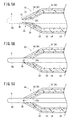
図2に示すように、送達先端領域30は、シャフト12の軸方向に平行に延びる平行部32と、平行部32の先端に連なり先端方向に向かって細くなるテーパ部34とを有する。平行部32の外径は、送達先端領域30よりも基端側の内管22の外径と一致している。平行部32の内周面の内径も、送達先端領域30よりも基端側の内管22の内径と一致し、ガイドワイヤGの外径よりも大きく設定されている。
As shown in FIG. 2, the delivery
テーパ部34は、シャフト12の最先端に位置し先細り形状に形成された部位である。テーパ部34の外周面34aは、断面視で、内管22の軸心に対し所定の角度(例えば、10°〜45°)で傾斜している。また、テーパ部34の外周面34aは、断面視で、平行部32との連結点33aから直線状に延在し、その先端頂部36(口縁)で内管22の先端開口26bを形成している。なお、外周面34aは直線状の断面形状だけでなく、円弧状を描く断面形状でもよい。
The tapered
テーパ部34の内周面38は、平行部32の内周面32aの先端に曲折して連なり内管側ルーメン26の先端側を狭める漏斗状の基端側内周面40と、基端側内周面40の先端に曲折して連なり先端方向に延びる先端側内周面42とを含む。基端側内周面40は、テーパ部34の外周面34aと同じ角度で傾斜し、テーパ部34を一定の厚みとしている。
The inner
先端側内周面42は、ガイドワイヤGの未挿入状態で、内管側ルーメン26の先端部をガイドワイヤGよりも細い円筒状の空洞部44に形成している。すなわち、送達先端領域30の基端側内周面40に連なる曲点33bから先端開口26bまでは、ガイドワイヤGの外径よりも小さな内径でシャフト12の軸方向に平行に延在している。そのため、内管側ルーメン26にガイドワイヤGを挿入した状態では、ガイドワイヤGの外周面OGが先端側内周面42に接触して径方向外側に押し広げる。換言すれば、ガイドワイヤGは、先端側内周面42と面接触しつつ内管22の先端開口26bから送出される(図1も参照)。
The distal end side inner
また、テーパ部34の外周面34aと先端側内周面42は、相互に交わる点により先端頂部36を鋭角に形成している。従って、ガイドワイヤGの外周面OGと先端側内周面42が面接触した状態では、ガイドワイヤGの外周面OGとテーパ部34の外周面34aとの境界に段差が殆どない状態が構築される。
Moreover, the outer
以下、送達先端領域30の寸法についてその一例を説明する。先端側内周面42の内径DIは、ガイドワイヤGの外径DGにも依存するが、例えば、ガイドワイヤGの外径DGが0.35mmの場合は、0.3mm≦DI≦0.35mmに設定されることが好ましい。このように先端側内周面42の内径DIがガイドワイヤGの外径DGよりも小さければ、ガイドワイヤGを空洞部44に挿入した状態でクリアランスの発生がなくなる。また、先端側内周面42の内径DIがガイドワイヤGの外径DOよりも極端に狭くないため、内管22又はガイドワイヤGの相互間にかかる負荷を抑えることができる。なお、先端側内周面42は、内径DIがガイドワイヤGの外径DGと一致していてもガイドワイヤGの外周面OGに面接触する。この場合、先端側内周面42とガイドワイヤGの外周面OGとの接触圧が抑えられるので、送達先端領域30の弾性力は低くてもよい。
Hereinafter, an example of the dimensions of the
また、先端側内周面42は、先端開口26bから曲点33bまでの軸方向長さLfが、0mm<Lf≦3mmに設定されるとよい。これにより、カテーテル10は、ガイドワイヤGの外周面OGに対し面接触する範囲を持つので、テーパ部34の強度が高くなりカテーテル10の送達性能が向上する。また、ガイドワイヤGとの接触範囲が長くならずに、ガイドワイヤGの送出性を良好に確保することができる。
Further, the distal end side inner
さらに、テーパ部34の先端頂部36(外周面34a)の外径DOは、先端側内周面42の内径DIとほぼ変わらない寸法であることが好ましく、例えばDO=DI+0mm〜0.06mmの関係を満たすとよい。これにより、ガイドワイヤGの外周面OGと送達先端領域30の外周面34aとの間の段差をほぼなくすことができるので、細い血管内でもカテーテル10を良好に進出させることができる。
Further, the outer diameter D O of the tip apex portion 36 (outer
そして、送達先端領域30(内管22)は、ガイドワイヤGの挿入状態で、テーパ部34(すなわち先端側内周面42)の径方向への弾性変形を促す構成となっている。具体的には、機能が異なる複数の構成材料により、内管22を、内層50、中間層52及び外層54を含む多層構造に形成している。
And the delivery front-end | tip area | region 30 (inner pipe | tube 22) is the structure which promotes the elastic deformation to the radial direction of the taper part 34 (namely, front end side inner peripheral surface 42) in the insertion state of the guide wire G. Specifically, the
内管22の内層50は、内管側ルーメン26を直接囲う内周面を構成する層である。この内層50は、内管側ルーメン26に収容されたガイドワイヤGの摺動抵抗を下げる(滑り性を上げる)機能を有する。内層50は、内管22の軸方向に沿って同じ肉厚に形成され、基端開口26aを構成する基端縁22aからテーパ部34の先端側内周面42の途中箇所まで延在している。ガイドワイヤGは、この内層50に接触しても摩擦が低減されるので、シャフト12との相対移動を容易に行うことができる。
The
また、送達先端領域30の先端側内周面42は、曲点33bから先端開口26bに向かう途中位置まで内層50を形成することで、中間層52を内層50及び外層54によって塞いで先端側内周面42に露出しない構成としている。これにより、先端側内周面42の形成位置では、ガイドワイヤGの外周面OGに対する内層50の接触範囲が広がり、ガイドワイヤGをより円滑に出し入れすることができる。
Further, the inner
内層50を構成する材料は、特に限定されるものではないが、例えば、ポリテトラフルオロエチレン(PTFE)、テトラフルオロエチレン・エチレン共重合体(ETFE)、テトラフルオロエチレン・ヘキサフルオロプロピレン共重合体(FEP)等のフッ素系樹脂、高密度ポリエチレン(HDPE)、ポリアセタール(POM)、ポリフェニレンサルファイド(PPS)、ポリオレフィン系樹脂又はスーパエンプラ等の樹脂材料があげられる。また、内層50は所定の樹脂材料に潤滑剤を配合して形成してもよい。本実施形態では、内層50をPTFEにより構成している。
The material constituting the
内管22の中間層52は、内層50の外側に設けられ、内層50よりも柔軟性を有する層である。この中間層52は、内管22の弾力性を高めると共に、送達先端領域30のテーパ部34(先端開口26b及び先端側内周面42)を柔軟にして、径方向外側への弾性変形を促す機能を有する。
The
特に、本実施形態に係る中間層52は、その先端部が先端側内周面42の曲点33bを超えた先端側まで延在することで、テーパ部34に充分な弾性変形力を提供している。また、中間層52の肉厚は、内管22の基端縁22aから先端部に向かって徐々に増加するように設けられる。すなわち図3Aに示す送達先端領域30において、柔軟性を有する中間層52が厚肉となることで、テーパ部34がより一層変形し易くなっている。
In particular, the
また、中間層52は、図3Bに示すように、バルーン18の設置箇所で送達先端領域30よりも薄肉となっていることで、内管22に適度に曲がり易くする。そのため、内管22のキンクの発生が抑えられると共に、たとえ内管22が折れ曲がったとしても復元がスムーズになされる。
Further, as shown in FIG. 3B, the
さらに、中間層52は、図3Cに示すように、外管20と接続する基端側でバルーン18の設置箇所よりも薄肉となっている。このため、外管20に対する内管22の揺動を抑えることができる。
Furthermore, as shown in FIG. 3C, the
中間層52を構成する材料は、特に限定されるものではないが、ポリ塩化ビニル系エラストマー、オレフィン系エラストマー、ポリエステル系エラストマー、ポリアミド系エラストマー、ポリウレタン系エラストマー、スチレン系エラストマーやそれら混合物等からなるエラストマー、或いは、天然ゴム、イソプレンゴム、ブチルゴム、クロロプレンゴム、ニトリル−ブタジエンゴム、スチレン−ブタジエンゴム、シリコーンゴム等の各種ゴム材料があげられる。本実施形態では、中間層52をポリウレタンエラストマーにより構成している。
The material constituting the
一方、内管22の外層54は、中間層52の外側に設けられ、内管22の外観を構成する層である。外層54は、内層50よりも柔軟性を有し、且つ中間層52よりも硬質性(剛性)を有するように形成される。これにより、シャフト12の先端は、適度に柔軟でありつつ、外周面の耐性を高めて、血管内での送達性能(狭窄部に対する貫通性等)が向上する。
On the other hand, the
この外層54は、基端縁22aから、送達先端領域30の先端頂部36まで延在している。そして、外層54の肉厚は、中間層52の肉厚とは逆に、内管22の基端縁22aから先端部に向かって徐々に減少するように設けられる。より詳細には、図3Aに示すように、送達先端領域30において薄肉に形成されて、中間層52の弾性力が発揮し易いように構成される。すなわち、先端側内周面42の形成箇所の壁部は、中間層52が多く占める一方で外層54が少なく中間層52を覆うことで、空洞部44へのガイドワイヤGの挿入状態で、径方向外側に弾性的に押し広げられ易くなる。また、外層54が中間層52を覆うことで、送達先端領域30全体が外層54で保護され、シャフト12の送達性能を高くすることができる。
This
また、外層54は、図3Bに示すように、バルーン18の設置箇所で送達先端領域30よりも厚肉となっていることで、内管22の剛性を高めると共に、中間層52と協働することで形状維持力を向上する。よって、バルーン18を強固に支持し、拡張時の処置を良好に実施させることができる。
Further, as shown in FIG. 3B, the
さらに、外層54は、図3Cに示すように、外管20と接続する基端側でバルーン18の設置箇所よりも厚肉になっていることで、内管22の基端部の剛性を高めて外管20の側面に対する内管22の支持力を高めることができる。
Further, as shown in FIG. 3C, the
外層54を構成する材料は、特に限定されるものではないが、ポリオレフィン(例えば、ポリエチレン、ポリプロピレン、ポリブテン、エチレン−プロピレン共重合体、エチレン−酢酸ビニル共重合体、アイオノマー、或いはこれら二種以上の混合物等)、ポリスチレン、ポリ塩化ビニル、ポリアミド、ポリエステル、ポリウレタン、ポリイミド、フッ素系樹脂等の高分子材料又はこれらの混合物があげられる。特に、外層54は、内管22の外周面を構成するため、バルーン18と融着し易いように、バルーン18の構成材料を含むものを選択するとよい。本実施形態では、バルーン18をポリアミドで構成していることに基づき、外層54もポリアミドを適用している。
The material constituting the
カテーテル10の内管22は、以上の積層構造に形成される。ここで、各層の硬質性を適用樹脂の性質で単純に比較すると、基本的には中間層52<外層54<内層50の順に高くなる。なお、各層の硬質性は、中間層52<外層54<内層50の順以外にも、中間層52<内層50<外層54となっていてもよく、中間層52<内層50=外層54となっていてもよい。例えば内層50が外層54より柔軟であれば、先端開口26bの拡径をより容易に促すことができる。この場合、内層50は、ガイドワイヤGの摺動抵抗を下げる潤滑剤を配合して構成するとよい。
The
なお、内管22は、内層50、中間層52、外層54の3層構造に限定されず、送達先端領域30の先端開口26b及び先端側内周面42を径方向に押し広げることが可能な種々の構造(単層、2層又は4層以上の構造)を採用し得る。また、内管22は、中間層52と外層54の肉厚を、内管22の軸方向に沿って徐々に変化する構成だけでなく、軸方向の所定位置を境界として段階的に変化させる構成でもよい。例えば、送達先端領域30にのみ内層50と外層54の間に中間層52を設けて、バルーン18の設置箇所や外管20内では内層50と外層54のみで構成してもよい。さらに、送達先端領域30は、内管22と一体成形されるだけでなく、別部材(先端チップ)としてシャフト12の先端に固着される構成であってもよい。
The
本実施形態に係るカテーテル10は、基本的には以上のように構成され、以下、その作用効果について説明する。
The
カテーテル10は、上述したようにガイドワイヤGをシャフト12の内管側ルーメン26に挿入し先端開口26bから送出した状態で、このガイドワイヤGの案内下に血管内の病変部に送達される。そして、本実施形態に係るカテーテル10の送達先端領域30は、先端側内周面42がガイドワイヤGの外径DGよりも小さい内径DIとなっていることで、図1に示すように、ガイドワイヤGの挿入状態では、先端側内周面42がガイドワイヤGに面接触する。その一方で、テーパ部34の外周面34aは、先端開口26bに向かって小径になっている。このため、ガイドワイヤGの外周面OGとテーパ部34の外周面34aとの段差を殆どなくした(段差を可及的に小さくした)状態となる。
The
ここで、従来のカテーテルにおいて、ガイドワイヤGが挿入されるガイドワイヤルーメンは、ガイドワイヤGよりも大径に形成されることが前提となっている。この場合、ガイドワイヤGの外周面OGとカテーテルの送達先端領域の外周面との間には、段差が少なからず形成される。この段差は、カテーテルの送達時に血管の細い箇所に引っ掛かる場合があり送達性能を下げる原因となる。 Here, in the conventional catheter, it is assumed that the guide wire lumen into which the guide wire G is inserted is formed to have a larger diameter than the guide wire G. In this case, not a few steps are formed between the outer peripheral surface OG of the guide wire G and the outer peripheral surface of the delivery tip region of the catheter. This level | step difference may be caught in the fine location of the blood vessel at the time of the delivery of a catheter, and causes a fall in delivery performance.
これに対し、本実施形態に係るカテーテル10は、送達先端領域30を軸心のガイドワイヤGに向かって充分に先細り(傾斜)した形状とし、段差が可及的に少なくなっている。そのため、例えば血管内の強度の狭窄部でも円滑に通過可能な送達性能が得られる。シャフト12は、ガイドワイヤGに面接触する肉厚を有してテーパ部34を構成するので、送達先端領域30の強度を充分に確保することができる。
On the other hand, the
また、送達先端領域30が内層50、中間層52、外層54を有することで、ガイドワイヤGを先端側内周面42に通すと中間層52の弾性力により先端側内周面42を径方向外側に容易に押し広げることができる。そして内層50は、ガイドワイヤGの摺動抵抗を下げるので、ガイドワイヤGの送出がより円滑化する。中間層52が先端側内周面42に重なる位置まで設けられることで、カテーテル10は、テーパ部34の形状を崩すことを抑制しつつ、先端側内周面42を良好に径方向外側に変形させる。
In addition, since the
さらに、先端側内周面42が内層50及び外層54により構成されることで、カテーテル10は、テーパ部34の外周面34aから内層50の露出を防ぐことができ、内層50が硬質に形成されていても血管に接触することを回避することが可能となる。先端開口26bの先端頂部36が外層54により構成されることで、ガイドワイヤGの外周面OGとの境界部分に外層54が配置される。この外層54によりテーパ部34の捲れや潰れを抑制することができる。
Furthermore, since the distal inner
またさらに、中間層52が内管22の周方向全周にわたって設けられることで、中間層52の断面積が変化する構造を容易に製造することができる。また中間層52が徐々に大きくなるので、カテーテル10の物性を徐々に変化させて、急激な物性変化による送達性能の低下を防ぐことができる。
Furthermore, since the
なお、医療用長尺体10は、上記の実施形態に限定されるものではなく、種々の応用例や変形例をとり得る。例えば、医療用長尺体10は、カテーテルだけでなく、ガイドワイヤGによって生体管腔内の所望箇所に案内されて治療又は診断を施す種々の治療デバイスを含むものである。要するに、上述した構成は、医療用長尺体10においてガイドワイヤGを送出する箇所に適用可能なものである。
In addition, the medical
以下、医療用長尺体10の変形例について図4A〜図5Cを参照して、幾つか具体的に説明する。なお、以下の説明において、本実施形態に係る医療用長尺体10と同一の構成又は同一の機能を有する構成には本実施形態と同じ符号を付し、その詳細な説明については省略する。
Hereinafter, some modified examples of the medical
第1変形例に係る内管60は、図4A〜図4Cに示す断面図のように、内層50、中間層52、外層54からなる積層構造のうち、中間層52を線条層62に形成した点で、本実施形態に係る内管22と異なる。線条層62は、内管60の軸方向に沿って基端縁22aからテーパ部34の途中位置まで延び、且つ内層50の周方向に沿って複数(本実施形態では8本)設けられている。外層54は、この線条層62を覆うように線条層62の外側、及び2つの線条層62の間に設けられる。
In the
また、各線条層62は、基端縁22a側の断面積が小さく先端方向に向かって徐々に断面積が大きくなるように形成される。このように形成されることで、内管22の急激な物性変化が抑えられる。またテーパ部34では、太い(断面積が大きい)線条層62により先端側内周面42を良好に径方向に弾性変形させることができる。
Each
第2変形例に係る内管70は、図5Aに示すように、ガイドワイヤGの未挿入状態で、先端側内周面72を曲点33bから先端開口26bに向かって内管70の軸心側に傾斜する形状としている点で、本実施形態に係る内管22と異なる。このように構成しても、ガイドワイヤGの挿入状態(図5A中の2点鎖線参照)で、曲点33bを基点に先端側内周面72を先端側且つ径方向外側に押し広げることにより、先端側内周面72とガイドワイヤGの外周面OGを面接触させることができる。
As shown in FIG. 5A, the
第3変形例に係る内管80は、図5Bに示すように、内層50を、外層54が延在する先端頂部36まで延びるように構成している点で、本実施形態に係る内管22と異なる。すなわち、先端側内周面82をほぼ全て内層50で構成し外層54を僅かな部分としている。このように、潤滑な内層50を先端頂部36まで設けることで、ガイドワイヤGの摺動性をより一層高めることができる。また、外層54により先端頂部36を覆っているので、本実施形態と同様に血管に対する内管80の耐性を高めることができる。
As shown in FIG. 5B, the
第4変形例に係る内管90は、図5Cに示すように、先端側内周面92を内層50、中間層52及び外層54により構成している点で、本実施形態に係る内管22と異なる。このように、先端側内周面92を3層に構成しても、本実施形態の内管22とほぼ同様の効果を得ることができる。また、3層構造の内管90を切断することで、先端側内周面92を簡単に構成することができるので、カテーテル10の製造作業が単純化し製造コストを下げることができる。
As shown in FIG. 5C, the
或いは、カテーテル10の送達先端領域30は、先端部に弾性力が高く柔軟な中間層52を露出して、テーパ部34の外周面34aを構成してもよい。要するに、送達先端領域30を構成する積層構造の構成は、ガイドワイヤGの外周面OGとの段差を可及的に少なくし、且つガイドワイヤGを送出できれば、特に限定されるものではない。
Alternatively, the
上記において、本発明について好適な実施形態を挙げて説明したが、本発明は前記実施形態に限定されるものではなく、本発明の要旨を逸脱しない範囲において、種々の改変が可能なことは言うまでもない。 In the above description, the present invention has been described with reference to preferred embodiments. However, the present invention is not limited to the above-described embodiments, and various modifications can be made without departing from the scope of the present invention. Yes.
10…医療用長尺体、バルーンカテーテル
12…シャフト 18…バルーン
20…外管 22、60、70、80、90…内管
26…内管側ルーメン 26b…先端開口
30…送達先端領域 32…平行部
34…テーパ部 34a…外周面
36…先端頂部 40…基端側内周面
42、72、82、92…先端側内周面
50…内層 52…中間層
54…外層 62…線条層
G…ガイドワイヤ
DESCRIPTION OF
Claims (10)
前記本体部の先端領域は、
前記先端開口に向かって外径が細くなるテーパ部を備え、
前記テーパ部は、前記先端開口に先端頂部を備え、
さらに、前記テーパ部の前記先端頂部から基端方向に延在し、且つ前記テーパ部の軸方向に沿った長さよりも短い範囲に形成される内周面を備える
ことを特徴とする医療用長尺体。 A medical elongated body comprising a main body including a lumen that accommodates a guide wire and a distal end opening that is connected to the lumen and delivers the guide wire,
The tip region of the main body is
A tapered portion having an outer diameter that decreases toward the tip opening,
The tapered portion includes a tip apex at the tip opening,
The medical length further includes an inner peripheral surface extending in a proximal direction from the tip top of the tapered portion and formed in a range shorter than a length along the axial direction of the tapered portion. Scale.
前記先端領域は、
前記ガイドワイヤの摺動抵抗を下げる内層と、
前記内層の外側に設けられ前記内層よりも柔軟性を有する中間層と、
前記中間層の外側に設けられ前記中間層よりも硬質性を有する外層と、を含む多層構造に形成され、
前記内周面は、少なくとも前記内層を含む
ことを特徴とする医療用長尺体。 The medical elongated body according to claim 1,
The tip region is
An inner layer for reducing the sliding resistance of the guide wire;
An intermediate layer provided outside the inner layer and having more flexibility than the inner layer;
An outer layer provided on the outer side of the intermediate layer and having a harder property than the intermediate layer, and is formed in a multilayer structure,
The medical peripheral body, wherein the inner peripheral surface includes at least the inner layer.
前記中間層の先端部は、前記内周面の基端部を超える位置まで設けられる
ことを特徴とする医療用長尺体。 The medical elongated body according to claim 2,
The medical long body, wherein a distal end portion of the intermediate layer is provided to a position exceeding a proximal end portion of the inner peripheral surface.
前記内周面は、前記中間層と前記外層の少なくとも一方を含んで構成される
ことを特徴とする医療用長尺体。 The medical elongated body according to claim 2 or 3,
The inner peripheral surface is configured to include at least one of the intermediate layer and the outer layer.
前記先端開口の口縁は、前記外層により構成される
ことを特徴とする医療用長尺体。 The medical elongated body according to claim 4,
The long edge for medical use, wherein a lip of the distal end opening is constituted by the outer layer.
前記先端領域は、前記内層、前記中間層及び前記外層を有して軸方向に延在する管体の先端側に位置し、
前記先端領域の前記中間層の断面積は、前記管体基端側の前記中間層の断面積よりも大きい
ことを特徴とする医療用長尺体。 In the medical elongate body of any one of Claims 2-5,
The tip region is located on the tip side of a tubular body that has the inner layer, the intermediate layer, and the outer layer and extends in the axial direction;
The medical elongated body, wherein a cross-sectional area of the intermediate layer in the distal end region is larger than a cross-sectional area of the intermediate layer on the proximal end side of the tubular body.
前記中間層は、前記管体の周方向全周にわたって設けられ、その断面積が前記管体基端側から先端方向に向かって徐々に大きくなる
ことを特徴とする医療用長尺体。 The medical elongated body according to claim 6, wherein
The said intermediate | middle layer is provided over the circumferential direction perimeter of the said tubular body, The cross-sectional area becomes large gradually toward the front end direction from the said tubular body base end side. The medical elongate body characterized by the above-mentioned.
前記中間層は、前記管体の軸方向に延在する線条層として前記管体の周方向に沿って複数設けられ、その断面積の合計が前記管体基端側から先端方向に向かって徐々に大きくなる
ことを特徴とする医療用長尺体。 The medical elongated body according to claim 6, wherein
The intermediate layer is provided in a plurality along the circumferential direction of the tubular body as a linear layer extending in the axial direction of the tubular body, and the total cross-sectional area is from the proximal end side of the tubular body toward the distal direction. Medical long body characterized by gradual growth.
前記医療用長尺体は、前記先端領域の基端側に拡張及び縮小可能な拡縮体を有し、
前記外層と前記拡縮体を構成する材料が同じ材料からなる
ことを特徴とする医療用長尺体。 In the medical elongate body of any one of Claims 2-8,
The medical elongated body has an expandable / contractible body that can be expanded and contracted on the proximal end side of the distal end region,
The medical elongate body, wherein the outer layer and the material constituting the expansion / contraction body are made of the same material.
前記内周面は、前記内腔の軸方向に沿って平行に又は先端方向に向かって細く形成され、前記テーパ部の外周面との間で鋭角を形成する
ことを特徴とする医療用長尺体。 In the medical elongate body of any one of Claims 1-9,
The medical inner length is characterized in that the inner peripheral surface is formed to be thin along the axial direction of the lumen in parallel or toward the distal end, and to form an acute angle with the outer peripheral surface of the tapered portion. body.
Priority Applications (1)
| Application Number | Priority Date | Filing Date | Title |
|---|---|---|---|
| JP2015000742A JP2016123742A (en) | 2015-01-06 | 2015-01-06 | Long body for medical purpose |
Applications Claiming Priority (1)
| Application Number | Priority Date | Filing Date | Title |
|---|---|---|---|
| JP2015000742A JP2016123742A (en) | 2015-01-06 | 2015-01-06 | Long body for medical purpose |
Publications (1)
| Publication Number | Publication Date |
|---|---|
| JP2016123742A true JP2016123742A (en) | 2016-07-11 |
Family
ID=56358447
Family Applications (1)
| Application Number | Title | Priority Date | Filing Date |
|---|---|---|---|
| JP2015000742A Pending JP2016123742A (en) | 2015-01-06 | 2015-01-06 | Long body for medical purpose |
Country Status (1)
| Country | Link |
|---|---|
| JP (1) | JP2016123742A (en) |
Cited By (1)
| Publication number | Priority date | Publication date | Assignee | Title |
|---|---|---|---|---|
| JP2018050722A (en) * | 2016-09-27 | 2018-04-05 | テルモ株式会社 | Catheter and method for using the same |
Citations (6)
| Publication number | Priority date | Publication date | Assignee | Title |
|---|---|---|---|---|
| US4886506A (en) * | 1986-12-23 | 1989-12-12 | Baxter Travenol Laboratories, Inc. | Soft tip catheter |
| US20070282367A1 (en) * | 2005-01-21 | 2007-12-06 | Andrew Jeffrey | Catheter having a soft distal tip |
| JP2011125737A (en) * | 2011-02-25 | 2011-06-30 | Asahi Intecc Co Ltd | Catheter |
| JP2012196389A (en) * | 2011-03-23 | 2012-10-18 | Goodtec Co Ltd | Catheter |
| JP2014097090A (en) * | 2012-11-13 | 2014-05-29 | Terumo Corp | Catheter |
| JP2014517725A (en) * | 2011-04-05 | 2014-07-24 | サーモピューティックス インコーポレイテッド | Microcatheter having a distal tip and a proximal solution lumen |
-
2015
- 2015-01-06 JP JP2015000742A patent/JP2016123742A/en active Pending
Patent Citations (6)
| Publication number | Priority date | Publication date | Assignee | Title |
|---|---|---|---|---|
| US4886506A (en) * | 1986-12-23 | 1989-12-12 | Baxter Travenol Laboratories, Inc. | Soft tip catheter |
| US20070282367A1 (en) * | 2005-01-21 | 2007-12-06 | Andrew Jeffrey | Catheter having a soft distal tip |
| JP2011125737A (en) * | 2011-02-25 | 2011-06-30 | Asahi Intecc Co Ltd | Catheter |
| JP2012196389A (en) * | 2011-03-23 | 2012-10-18 | Goodtec Co Ltd | Catheter |
| JP2014517725A (en) * | 2011-04-05 | 2014-07-24 | サーモピューティックス インコーポレイテッド | Microcatheter having a distal tip and a proximal solution lumen |
| JP2014097090A (en) * | 2012-11-13 | 2014-05-29 | Terumo Corp | Catheter |
Cited By (1)
| Publication number | Priority date | Publication date | Assignee | Title |
|---|---|---|---|---|
| JP2018050722A (en) * | 2016-09-27 | 2018-04-05 | テルモ株式会社 | Catheter and method for using the same |
Similar Documents
| Publication | Publication Date | Title |
|---|---|---|
| US11712544B2 (en) | Guide extension catheter | |
| JP3915862B2 (en) | catheter | |
| CN110430912B (en) | Hemostatic valve design for introducer sheaths | |
| JP4771456B2 (en) | catheter | |
| JP6163829B2 (en) | Tip for catheter | |
| TW201922310A (en) | Catheter and catheter kit | |
| JP2015181485A (en) | catheter assembly | |
| US10702675B2 (en) | Catheter for insertion into branched blood vessel | |
| JP5347425B2 (en) | Thrombus suction catheter assembly | |
| US10994094B2 (en) | Catheter | |
| JPWO2011033938A1 (en) | catheter | |
| JP2015173913A (en) | Angioplasty catheter | |
| CN115666698B (en) | catheter | |
| JP2013223663A (en) | Protective sleeve for balloon catheter, balloon catheter system, and stent delivery system | |
| JP2011110144A (en) | Catheter for intravascular treatment | |
| JP3206339U (en) | Guiding catheter assembly | |
| JP2016123742A (en) | Long body for medical purpose | |
| JP2019187770A (en) | catheter | |
| JP2021146136A (en) | Balloon catheter support device | |
| JP6162802B2 (en) | catheter | |
| JPWO2015141392A1 (en) | Catheter and catheter set | |
| JP2016154631A (en) | Catheter | |
| JP2013013654A (en) | Catheter | |
| JP2024013595A (en) | balloon catheter | |
| WO2022154118A1 (en) | Catheter and catheter assembly |
Legal Events
| Date | Code | Title | Description |
|---|---|---|---|
| A621 | Written request for application examination |
Free format text: JAPANESE INTERMEDIATE CODE: A621 Effective date: 20171212 |
|
| A977 | Report on retrieval |
Free format text: JAPANESE INTERMEDIATE CODE: A971007 Effective date: 20180809 |
|
| A131 | Notification of reasons for refusal |
Free format text: JAPANESE INTERMEDIATE CODE: A131 Effective date: 20180904 |
|
| A02 | Decision of refusal |
Free format text: JAPANESE INTERMEDIATE CODE: A02 Effective date: 20190305 |