JP2016122199A - Imaging device - Google Patents

Imaging device Download PDF

Info

Publication number
JP2016122199A
JP2016122199A JP2016015007A JP2016015007A JP2016122199A JP 2016122199 A JP2016122199 A JP 2016122199A JP 2016015007 A JP2016015007 A JP 2016015007A JP 2016015007 A JP2016015007 A JP 2016015007A JP 2016122199 A JP2016122199 A JP 2016122199A
Authority
JP
Japan
Prior art keywords
subject
image
exposure period
control unit
imaging
Prior art date
Legal status (The legal status is an assumption and is not a legal conclusion. Google has not performed a legal analysis and makes no representation as to the accuracy of the status listed.)
Granted
Application number
JP2016015007A
Other languages
Japanese (ja)
Other versions
JP6089232B2 (en
Inventor
基範 小倉
Motonori Ogura
基範 小倉
Current Assignee (The listed assignees may be inaccurate. Google has not performed a legal analysis and makes no representation or warranty as to the accuracy of the list.)
Panasonic Intellectual Property Management Co Ltd
Original Assignee
Panasonic Intellectual Property Management Co Ltd
Priority date (The priority date is an assumption and is not a legal conclusion. Google has not performed a legal analysis and makes no representation as to the accuracy of the date listed.)
Filing date
Publication date
Application filed by Panasonic Intellectual Property Management Co Ltd filed Critical Panasonic Intellectual Property Management Co Ltd
Publication of JP2016122199A publication Critical patent/JP2016122199A/en
Application granted granted Critical
Publication of JP6089232B2 publication Critical patent/JP6089232B2/en
Active legal-status Critical Current
Anticipated expiration legal-status Critical

Links

Images

Abstract

PROBLEM TO BE SOLVED: To provide an imaging device realizing a more convenient focus operation using a distance to a subject.SOLUTION: An imaging device comprises: a focus lens which has a focusing position and forms a subject image of a subject; an imaging sensor which generates imaging data by picking up the subject image; and a control unit which controls the focus lens. The control unit operates so as to determine a controlled variable for the focus lens in a second exposure period after a first exposure period, the controlled variable controlling a moving speed of the focusing position, on the basis of the imaging data generated by the imaging sensor by picking up the subject image in the first exposure period. Furthermore, the control unit operates so that the image sensor picks up the subject image while moving the focusing position at the moving speed corresponding to the determined controlled variable in the second exposure period.SELECTED DRAWING: Figure 1

Description

本開示は撮像装置に関する。   The present disclosure relates to an imaging apparatus.

特許文献1は、DFD(Depth From Defocus)方式のシステムを採用した撮像装置を開示している。この撮像装置は、複数種類のボケが得られるようにフォーカス制御を実施し、撮像素子によりボケの大きさが異なる複数の画像を取得する。次に、撮像装置は、ボケの大きさが異なる複数の画像に基づいて、被写体距離を算出する。そして、撮像装置は、算出した被写体距離に基づいて、フォーカス制御を実施する。   Patent Document 1 discloses an imaging apparatus that employs a DFD (Depth From Defocus) system. The imaging apparatus performs focus control so that a plurality of types of blur can be obtained, and acquires a plurality of images having different blur sizes by the imaging element. Next, the imaging apparatus calculates the subject distance based on a plurality of images having different blur sizes. Then, the imaging apparatus performs focus control based on the calculated subject distance.

特開2011−15163号公報JP 2011-15163 A

DFD方式などのシステムを採用することで、撮像装置は被写体までの距離を検出することができる。検出された距離を用いることにより、より便利なフォーカス動作の実現が期待される。   By employing a system such as the DFD method, the imaging apparatus can detect the distance to the subject. By using the detected distance, it is expected to realize a more convenient focus operation.

本開示は、被写体までの距離を用いて、より便利なフォーカス動作を実現する撮像装置を提供する。   The present disclosure provides an imaging apparatus that realizes a more convenient focus operation using a distance to a subject.

上記課題を解決するために、本開示の撮像装置は、合焦位置を有して被写体の被写体像を形成するフォーカスレンズと、被写体像を撮像することにより撮像データを生成する撮像センサと、フォーカスレンズを制御する制御部とを備える。制御部は、第1の露光期間において被写体像を撮像することによって撮像センサで生成された撮像データに基づき、第1の露光期間における撮像装置から被写体までの距離の変化を検出するように動作する。制御部は、距離の検出された変化に基づいて、合焦位置を第1の露光期間よりも後の第2の露光期間において移動させる移動速度を制御する制御量を決定するように動作する。さらに、制御部は、第2の露光期間において、決定した制御量に対応する移動速度で合焦位置を移動させて撮像センサに被写体像を撮像させるように動作する。   In order to solve the above problems, an imaging apparatus according to the present disclosure includes a focus lens that forms a subject image of a subject with a focus position, an imaging sensor that generates imaging data by capturing the subject image, a focus A control unit for controlling the lens. The control unit operates to detect a change in the distance from the imaging device to the subject in the first exposure period based on the imaging data generated by the imaging sensor by capturing the subject image in the first exposure period. . The control unit operates to determine a control amount for controlling the moving speed for moving the in-focus position in the second exposure period after the first exposure period based on the detected change in distance. Further, the control unit operates to cause the imaging sensor to capture the subject image by moving the in-focus position at the moving speed corresponding to the determined control amount in the second exposure period.

本開示によれば、被写体までの距離を用いて、より便利なフォーカス動作を実現する撮像装置を提供できる。   According to the present disclosure, it is possible to provide an imaging apparatus that realizes a more convenient focusing operation using the distance to the subject.

実施の形態におけるデジタルビデオカメラの電気的構成を示すブロック図1 is a block diagram showing an electrical configuration of a digital video camera in an embodiment 実施の形態におけるデジタルビデオカメラの動作のブロック図Block diagram of operation of digital video camera in embodiment 実施の形態におけるデジタルビデオカメラの動作のイメージ図Image diagram of operation of digital video camera in embodiment 実施の形態におけるデジタルビデオカメラのDFD演算のイメージ図Diagram of DFD operation of digital video camera in embodiment 実施の形態におけるデジタルビデオカメラの複数の被写体距離に対するズームトラッキングテーブルを示す図The figure which shows the zoom tracking table with respect to several object distance of the digital video camera in embodiment (a)実施の形態におけるデジタルビデオカメラでの被写体の移動を示すイメージ図(b)実施の形態におけるデジタルビデオカメラでの被写体の移動を示すイメージ図(A) Image diagram showing movement of subject in digital video camera in the embodiment (b) Image diagram showing movement of subject in the digital video camera in the embodiment 実施の形態におけるデジタルビデオカメラの動作のフローチャートFlowchart of operation of digital video camera in embodiment 実施の形態におけるデジタルビデオカメラの動作を示すイメージ図The image figure which shows operation | movement of the digital video camera in embodiment 実施の形態におけるデジタルビデオカメラのズームトラッキングテーブルを示す図The figure which shows the zoom tracking table of the digital video camera in embodiment

以下、適宜図面を参照しながら、実施の形態を詳細に説明する。但し、必要以上に詳細な説明は省略する場合がある。例えば、既によく知られた事項の詳細説明や実質的に同一の構成に対する重複説明を省略する場合がある。これは、以下の説明が不必要に冗長になるのを避け、当業者の理解を容易にするためである。   Hereinafter, embodiments will be described in detail with reference to the drawings as appropriate. However, more detailed description than necessary may be omitted. For example, detailed descriptions of already well-known matters and repeated descriptions for substantially the same configuration may be omitted. This is to avoid the following description from becoming unnecessarily redundant and to facilitate understanding by those skilled in the art.

なお、発明者は、当業者が本開示を十分に理解するために添付図面および以下の説明を提供するのであって、これらによって請求の範囲に記載の主題を限定することを意図するものではない。   In addition, the inventor provides the accompanying drawings and the following description in order for those skilled in the art to fully understand the present disclosure, and is not intended to limit the claimed subject matter. .

撮像装置から被写体までの距離である被写体距離を計測する数ある方法の1つに、撮影された画像に生じるボケ量(Defocus)の相関値を利用するDFD(Depth from Defocus)と呼ばれる手法がある。一般に、撮影画像に生じるボケ量は、撮影時のフォーカス位置と被写体距離との関係に応じて撮像装置毎に一意に決まる。DFD演算ではこの特性を利用し、フォーカス位置を変動させることでボケ量の異なる2枚の画像を意図的に作り出し、ボケ量の違いと点拡がり関数(Point spread function、PSF)とから被写体距離を計測する。実施の形態にかかる撮像装置は、DFD演算を用いて被写体距離を計測することによりオートフォーカス制御を行う。   One of many methods for measuring the subject distance, which is the distance from the imaging device to the subject, is a technique called DFD (Depth from Defocus) that uses a correlation value of a blur amount (Defocus) generated in a captured image. . In general, the amount of blur that occurs in a captured image is uniquely determined for each imaging device in accordance with the relationship between the focus position at the time of shooting and the subject distance. In the DFD calculation, this characteristic is used to intentionally create two images with different amounts of blur by changing the focus position, and the subject distance is calculated from the difference in the amount of blur and the point spread function (PSF). measure. The imaging apparatus according to the embodiment performs autofocus control by measuring a subject distance using DFD calculation.

以下、実施の形態における撮像装置の構成および動作について説明する。   Hereinafter, the configuration and operation of the imaging apparatus according to the embodiment will be described.

〔1.撮像装置の電気的構成〕
図1は実施の形態における撮像装置であるデジタルビデオカメラ100の電気的構成を示すブロック図である。デジタルビデオカメラ100は、1以上のレンズからなる光学系110を備える。光学系110は被写体からの光により被写体像をCMOSイメージセンサ140上に形成する。形成された被写体像を撮像センサであるCMOSイメージセンサ140で撮像する。CMOSイメージセンサ140は撮像した被写体像に基づいて画像データを生成する。CMOSイメージセンサ140で生成された画像データは、ADC150でデジタル信号に変換された後、画像処理部160で各種処理が施され、メモリカード200に格納される。以下、デジタルビデオカメラ100の構成を詳細に説明する。
[1. Electrical configuration of imaging device]
FIG. 1 is a block diagram showing an electrical configuration of a digital video camera 100 which is an imaging apparatus according to an embodiment. The digital video camera 100 includes an optical system 110 including one or more lenses. The optical system 110 forms a subject image on the CMOS image sensor 140 by light from the subject. The formed subject image is picked up by a CMOS image sensor 140 which is an image pickup sensor. The CMOS image sensor 140 generates image data based on the captured subject image. Image data generated by the CMOS image sensor 140 is converted into a digital signal by the ADC 150, and then subjected to various processes by the image processing unit 160 and stored in the memory card 200. Hereinafter, the configuration of the digital video camera 100 will be described in detail.

実施の形態における光学系110は、ズームレンズ111、手振れ補正レンズ112、フォーカスレンズ113、絞り114により構成される。ズームレンズ111を光軸110Aに沿って移動させることにより、被写体像の拡大、縮小をすることができる。また、フォーカスレンズ113を光軸110Aに沿って移動させることにより被写体像のフォーカスを調整することができる。また、手振れ補正レンズ112は、光学系110の光軸110Aに垂直な面内で移動可能である。デジタルビデオカメラ100のブレを打ち消す方向に手振れ補正レンズ112を移動することで、デジタルビデオカメラ100のブレが撮像画像に与える影響を低減できる。また、絞り114は光軸110A上に位置する開口部114Aを有し、使用者の設定に応じて若しくは自動で開口部114Aの大きさを調整し、透過する光の量を調整する。   The optical system 110 in the embodiment includes a zoom lens 111, a camera shake correction lens 112, a focus lens 113, and a diaphragm 114. The subject image can be enlarged or reduced by moving the zoom lens 111 along the optical axis 110A. Further, the focus of the subject image can be adjusted by moving the focus lens 113 along the optical axis 110A. The camera shake correction lens 112 is movable in a plane perpendicular to the optical axis 110A of the optical system 110. By moving the camera shake correction lens 112 in a direction in which the blur of the digital video camera 100 is canceled, the influence of the blur of the digital video camera 100 on the captured image can be reduced. The diaphragm 114 has an opening 114A located on the optical axis 110A, and adjusts the size of the opening 114A according to the setting of the user or automatically to adjust the amount of transmitted light.

レンズ駆動部120は、ズームレンズ111を駆動するズームアクチュエータや、手ブレ補正レンズ112を駆動する手ブレ補正アクチュエータや、フォーカスレンズ113を駆動するフォーカスアクチュエータや、絞り114を駆動する絞りアクチュエータを含む。そして、レンズ駆動部120は、上記のズームアクチュエータや、フォーカスアクチュエータや、手ブレ補正アクチュエータや、絞りアクチュエータを制御する。   The lens driving unit 120 includes a zoom actuator that drives the zoom lens 111, a camera shake correction actuator that drives the camera shake correction lens 112, a focus actuator that drives the focus lens 113, and a diaphragm actuator that drives the diaphragm 114. The lens driving unit 120 controls the zoom actuator, the focus actuator, the camera shake correction actuator, and the aperture actuator.

CMOSイメージセンサ140は、光学系110で形成された被写体像を撮像してアナログ信号であるアナログ画像データを生成する。CMOSイメージセンサ140は、露光、転送、電子シャッタなどの各種動作を行う。   The CMOS image sensor 140 captures a subject image formed by the optical system 110 and generates analog image data that is an analog signal. The CMOS image sensor 140 performs various operations such as exposure, transfer, and electronic shutter.

A/Dコンバータ150は、CMOSイメージセンサ140で生成されたアナログ画像データをデジタル信号であるデジタル画像データに変換する。   The A / D converter 150 converts the analog image data generated by the CMOS image sensor 140 into digital image data that is a digital signal.

画像処理部160は、CMOSイメージセンサ140で生成された画像データに対して各種処理を施し、表示モニタ220に表示するための画像データを生成したり、メモリカード200に格納するための画像データを生成したりする。例えば、画像処理部160は、CMOSイメージセンサ140で生成された画像データに対して、ガンマ補正、ホワイトバランス補正、傷補正などの各種処理を行う。また、画像処理部160は、CMOSイメージセンサ140で生成された画像データを、H.264規格やMPEG2規格に準拠した圧縮形式等により圧縮する。画像処理部160は、DSPやマイコンなどで実現可能である。   The image processing unit 160 performs various processes on the image data generated by the CMOS image sensor 140, generates image data to be displayed on the display monitor 220, and stores image data to be stored in the memory card 200. Or generate. For example, the image processing unit 160 performs various processes such as gamma correction, white balance correction, and flaw correction on the image data generated by the CMOS image sensor 140. The image processing unit 160 converts the image data generated by the CMOS image sensor 140 into the H.264 format. It compresses by the compression format etc. based on H.264 standard or MPEG2 standard. The image processing unit 160 can be realized by a DSP, a microcomputer, or the like.

制御部180は、デジタルビデオカメラ100全体を制御する。制御部180は半導体素子などで実現できる。制御部180はハードウェアのみで構成してもよいし、ハードウェアとソフトウェアとを組み合わせることにより実現してもよい。制御部180は、マイコンなどで実現できる。   The control unit 180 controls the entire digital video camera 100. The control unit 180 can be realized by a semiconductor element or the like. The control unit 180 may be configured only by hardware, or may be realized by combining hardware and software. The control unit 180 can be realized by a microcomputer or the like.

バッファ170は、画像処理部160及び制御部180のワークメモリとして機能する。バッファ170は、例えば、DRAM、強誘電体メモリなどで実現できる。   The buffer 170 functions as a work memory for the image processing unit 160 and the control unit 180. The buffer 170 can be realized by, for example, a DRAM or a ferroelectric memory.

カードスロット190はメモリカード200を着脱可能に保持する。カードスロット190は機械的及び電気的にメモリカード200と接続可能である。メモリカード200はフラッシュメモリや強誘電体メモリなどを内部に含み、画像処理部160で生成された画像ファイル等のデータを格納できる。   The card slot 190 holds the memory card 200 in a detachable manner. The card slot 190 can be mechanically and electrically connected to the memory card 200. The memory card 200 includes a flash memory, a ferroelectric memory, and the like, and can store data such as an image file generated by the image processing unit 160.

内部メモリ240は、フラッシュメモリや強誘電体メモリなどで構成される。内部メモリ240は、デジタルビデオカメラ100全体を制御するための制御プログラム等を記憶する。また、内部メモリ240は点拡がり関数を格納している。   The internal memory 240 is composed of a flash memory or a ferroelectric memory. The internal memory 240 stores a control program for controlling the entire digital video camera 100 and the like. The internal memory 240 stores a point spread function.

操作部材210は使用者からの操作を受け付けるユーザーインターフェースの総称である。操作部材210は、例えば、使用者からの操作を受け付ける十字キーや決定釦等を含む。   The operation member 210 is a generic term for user interfaces that accept operations from the user. The operation member 210 includes, for example, a cross key that accepts an operation from the user, a determination button, and the like.

表示モニタ220は、CMOSイメージセンサ140で生成された画像データが示す画像や、メモリカード200から読み出された画像データが示す画像を表示できる画面220Aを有する。また、表示モニタ220は、デジタルビデオカメラ100の各種設定を行うための各種メニュー画面等も画面220Aに表示できる。表示モニタ220の画面220A上にはタッチパネル220Bが配置されている。タッチパネル220Bはユーザによりタッチされて各種タッチ操作を受け付けることができる。タッチパネル220Bに対するタッチ操作が示す指示は制御部180に通知され各種処理が行われる。   The display monitor 220 includes a screen 220 </ b> A that can display an image indicated by the image data generated by the CMOS image sensor 140 or an image indicated by the image data read from the memory card 200. The display monitor 220 can also display various menu screens for performing various settings of the digital video camera 100 on the screen 220A. A touch panel 220B is arranged on the screen 220A of the display monitor 220. Touch panel 220B is touched by the user and can accept various touch operations. The instruction indicated by the touch operation on the touch panel 220B is notified to the control unit 180 and various processes are performed.

角速度センサ250は、手振れ等に起因してデジタルビデオカメラ100に発生した角速度を検出する。角速度センサ250が検出した角速度は制御部180に通知される。制御部180は、角速度センサ250から通知された角速度により、デジタルビデオカメラ100に発生した角速度に基づく画像のブレを解消するよう手振れ補正レンズ112を駆動させることができる。   The angular velocity sensor 250 detects an angular velocity generated in the digital video camera 100 due to camera shake or the like. The angular velocity detected by the angular velocity sensor 250 is notified to the control unit 180. The control unit 180 can drive the camera shake correction lens 112 based on the angular velocity notified from the angular velocity sensor 250 so as to eliminate image blurring based on the angular velocity generated in the digital video camera 100.

〔2.デジタルビデオカメラ100の動作〕
〔2−1.DFD演算結果を用いたオートフォーカス動作〕
デジタルビデオカメラ100は、DFD演算の結果を用いてオートフォーカス動作を行う。図2は実施の形態におけるデジタルビデオカメラ100のDFD演算の結果を用いたフォーカスレンズ制御を説明するためのブロック図である。
[2. Operation of digital video camera 100]
[2-1. Autofocus operation using DFD calculation results]
The digital video camera 100 performs an autofocus operation using the result of the DFD calculation. FIG. 2 is a block diagram for explaining focus lens control using the result of the DFD calculation of the digital video camera 100 in the embodiment.

DFD演算回路161は、画像処理部160内に構成された演算回路であり、DFD演算を実施してDepthマップを作成する。具体的には、DFD演算回路161は、フォーカス位置を変動させることで、意図的に作り出したボケ量の異なる2枚の画像である観測画像PA、参照画像PBと点拡がり関数とから観測画像PA(参照画像PB)の各画素での被写体距離を示すDepthマップを作成する。   The DFD operation circuit 161 is an operation circuit configured in the image processing unit 160, and performs a DFD operation to create a depth map. Specifically, the DFD arithmetic circuit 161 changes the focus position, thereby observing the observation image PA based on the observation image PA, the reference image PB, and the point spread function, which are two images with different amounts of blur created intentionally. A depth map indicating the subject distance at each pixel of the (reference image PB) is created.

次に、DFD演算回路161は、作成したDepthマップを制御部180に通知する。制御部180は、通知されたDepthマップに基づいてフォーカスレンズ113を駆動するようレンズ駆動部120を制御する。   Next, the DFD arithmetic circuit 161 notifies the control unit 180 of the created depth map. The control unit 180 controls the lens driving unit 120 to drive the focus lens 113 based on the notified depth map.

以下、図2に示したDFD演算回路161によるDFD演算の詳細と、制御部180による被写体距離の決定の詳細について説明する。   Details of the DFD calculation by the DFD calculation circuit 161 shown in FIG. 2 and details of determination of the subject distance by the control unit 180 will be described below.

まず、DFD演算回路161によるDFD演算の詳細について説明する。図3は、実施の形態におけるデジタルビデオカメラ100のDFD演算におけるフォーカスレンズ113の移動を説明するためのイメージ図である。DFD演算において、制御部180はフォーカス位置を変動させることで、意図的にボケ量の異なる2枚の画像を作り出す。具体的には、図3に示すように、制御部180はレンズ駆動部120を制御して、時刻t1におけるフォーカスレンズ113の位置をフォーカス位置L1に設定する。同様に、時刻t2におけるフォーカスレンズ113の位置を、フォーカス位置L1と異なるフォーカス位置L2に設定する。CMOSイメージセンサ140は、フォーカスレンズ113がフォーカス位置L1にあるときに被写体を撮像して、観測画像PAを作成する。同様に、CMOSイメージセンサ140は、フォーカスレンズ113がフォーカス位置L2にあるときにその被写体を撮像して参照画像PBを作成する。観測画像PAと参照画像PBとは、撮像されたときのフォーカスレンズ113の位置が異なるので、同一被写体を撮像した画像ではあるが互いにボケ量が異なる。   First, details of the DFD calculation performed by the DFD calculation circuit 161 will be described. FIG. 3 is an image diagram for explaining the movement of the focus lens 113 in the DFD calculation of the digital video camera 100 according to the embodiment. In the DFD calculation, the control unit 180 intentionally creates two images with different amounts of blur by changing the focus position. Specifically, as shown in FIG. 3, the control unit 180 controls the lens driving unit 120 to set the position of the focus lens 113 at the time t1 to the focus position L1. Similarly, the position of the focus lens 113 at time t2 is set to a focus position L2 different from the focus position L1. The CMOS image sensor 140 images a subject when the focus lens 113 is at the focus position L1, and creates an observation image PA. Similarly, the CMOS image sensor 140 images the subject when the focus lens 113 is at the focus position L2, and creates a reference image PB. Since the observation image PA and the reference image PB are different in the position of the focus lens 113 when imaged, the amounts of blur are different from each other although they are images of the same subject.

図4は、実施の形態におけるデジタルビデオカメラ100のDFD演算による被写体距離の算出を説明するイメージ図である。DFD演算回路161は、観測画像PAを構成する各観測画素SA、参照画像PBを構成する各参照画素SBに対してDFD演算を行い、各画素SA(SB)での被写体距離を算出する。DFD演算回路161は、観測画素SAに複数の点拡がり関数を畳み込んで得られた結果である複数の観測画素CAを、観測画素CAと画像上の同じ座標の参照画素SBと照合する。その動作を以下に説明する。   FIG. 4 is a conceptual diagram illustrating calculation of the subject distance by DFD calculation of the digital video camera 100 according to the embodiment. The DFD calculation circuit 161 performs DFD calculation on each observation pixel SA that constitutes the observation image PA and each reference pixel SB that constitutes the reference image PB, and calculates a subject distance at each pixel SA (SB). The DFD arithmetic circuit 161 collates a plurality of observation pixels CA, which is a result obtained by convolving a plurality of point spread functions with the observation pixel SA, with a reference pixel SB having the same coordinates on the image as the observation pixel CA. The operation will be described below.

点拡がり関数は、光学系の点光源に対する応答を示す関数であり、ボケ量の変化を示す。点拡がり関数を、点光源の集合に対応する画像に畳み込む(Convolution)ことで、人為的にボケ画像を生成することができる。本実施の形態では、多数の被写体距離に対応して予め多数の点拡がり関数が内部メモリ240内に用意している。制御部180は、至近側から遠側までを16段階の被写体距離に分解し、それらの被写体距離にそれぞれ対応する16個の点拡がり関数PSF1〜PSF16を内部メモリ240に用意された多数の点拡がり関数から選択する。そして、制御部180は、選択した16個の点拡がり関数PSF1〜PSF16をDFD演算回路161に通知する。   The point spread function is a function indicating the response of the optical system to the point light source, and indicates a change in the amount of blur. By convolutioning the point spread function with an image corresponding to a set of point light sources (convolution), it is possible to artificially generate a blurred image. In the present embodiment, a large number of point spread functions are prepared in advance in the internal memory 240 corresponding to a large number of subject distances. The control unit 180 divides the subject distance from the closest side to the far side into 16 subject distances, and the 16 point spread functions PSF1 to PSF16 respectively corresponding to the subject distances are provided in a number of point spreads prepared in the internal memory 240. Select from functions. Then, the control unit 180 notifies the DFD arithmetic circuit 161 of the selected 16 point spread functions PSF1 to PSF16.

DFD演算回路161は、各観測画素SAでの被写体までの距離に対応した16個の点拡がり関数PSF1〜PSF16を各観測画素SAに畳み込みすることで、各観測画素SAでの被写体までの距離に対応した16個の観測画素CA1〜CA16を生成する。16個の観測画素CA1〜CA16は、畳み込まれている点拡がり関数がそれぞれ異なるので、それぞれ異なるボケ画像を形成する。   The DFD operation circuit 161 convolves the 16 point spread functions PSF1 to PSF16 corresponding to the distance to the subject at each observation pixel SA into each observation pixel SA, thereby obtaining the distance to the subject at each observation pixel SA. Corresponding 16 observation pixels CA1 to CA16 are generated. Since the 16 observation pixels CA1 to CA16 have different point spread functions that are convoluted, different blurred images are formed.

続いて、DFD演算回路161は、観測画素CA1〜CA16を参照画素SBと照合し、観測画素CA1〜CA16のうち参照画素SBとの差分値が最小となる観測画素CAnを判定する。そして、観測画素CAnに畳み込まれている点拡がり関数に対応する被写体距離を観測画素SAの被写体距離であると決定する。例えば、観測画素CA3と参照画素SBとの差分値が、他の観測画素CA1〜2、CA4〜16のそれぞれと参照画素SBとの差分値と比較して最小となる場合、DFD演算回路161は、観測画素CA3を作成する際に観測画素SAに畳み込んだ点拡がり関数PSF3に対応する被写体距離を観測画素SAでの被写体距離であると決定し、その被写体距離に対応した距離情報を出力する。   Subsequently, the DFD arithmetic circuit 161 collates the observation pixels CA1 to CA16 with the reference pixel SB, and determines an observation pixel CAn having a minimum difference value from the reference pixel SB among the observation pixels CA1 to CA16. Then, the subject distance corresponding to the point spread function convolved with the observation pixel CAn is determined to be the subject distance of the observation pixel SA. For example, when the difference value between the observation pixel CA3 and the reference pixel SB is minimum compared to the difference value between each of the other observation pixels CA1 to CA2 and CA4 to 16 and the reference pixel SB, the DFD arithmetic circuit 161 When the observation pixel CA3 is created, the subject distance corresponding to the point spread function PSF3 convolved with the observation pixel SA is determined as the subject distance at the observation pixel SA, and distance information corresponding to the subject distance is output. .

以上の動作を、観測画像PA及び参照画像PBの各画素について実施することにより、DFD演算回路161は各画素についての被写体距離の分布であるDepthマップを完成させる。実施の形態では各被写体までの距離に対応した16個の点拡がり関数を用いたので、Depthマップは16階調の被写体距離を示す。   By performing the above operation for each pixel of the observation image PA and the reference image PB, the DFD arithmetic circuit 161 completes a Depth map that is a distribution of subject distances for each pixel. In the embodiment, since 16 point spread functions corresponding to the distance to each subject are used, the Depth map indicates a subject distance of 16 gradations.

次に、制御部180はDFD演算により決定された被写体距離に基づいて、フォーカスレンズ113を移動させるべき位置である合焦位置を算出する。具体的には、制御部180は、トラッキングテーブルを参照して、求めた被写体距離と現在のズームレンズ111の位置とに基づいて合焦位置を算出する。図5は実施の形態におけるデジタルビデオカメラ100の複数の被写体距離に対するズームトラッキングテーブルを示す。図5に示すように、ズームトラッキングテーブルは、代表的ないくつかの被写体距離DL(図5では1m、2m、3m、無限遠)に対応してズームレンズ111の位置に対する合焦位置を示すカーブDM1〜DM4を含む。制御部180は、ズームトラッキングテーブルに記載のカーブを被写体距離について補間することで、代表的な被写体距離DL以外の被写体距離についてもフォーカスレンズ113を移動させるべき位置である合焦位置を算出することができる。   Next, the control unit 180 calculates a focus position, which is a position where the focus lens 113 should be moved, based on the subject distance determined by the DFD calculation. Specifically, the control unit 180 refers to the tracking table and calculates a focus position based on the obtained subject distance and the current position of the zoom lens 111. FIG. 5 shows a zoom tracking table for a plurality of object distances of the digital video camera 100 according to the embodiment. As shown in FIG. 5, the zoom tracking table is a curve indicating a focus position with respect to the position of the zoom lens 111 corresponding to some typical subject distances DL (1 m, 2 m, 3 m, and infinity in FIG. 5). Includes DM1-DM4. The control unit 180 interpolates the curve described in the zoom tracking table with respect to the subject distance, thereby calculating a focus position that is a position to move the focus lens 113 for subject distances other than the representative subject distance DL. Can do.

制御部180は、算出された被写体距離とズームトラッキングテーブルとに基づいて合焦位置を決定する。そして、制御部180は、レンズ駆動部120を制御することによりフォーカスレンズ113を合焦位置へと移動させ、フォーカスレンズ113を被写体に対して合焦させることができる。   The control unit 180 determines a focus position based on the calculated subject distance and the zoom tracking table. Then, the control unit 180 can move the focus lens 113 to the in-focus position by controlling the lens driving unit 120 to focus the focus lens 113 on the subject.

〔2−2.本露光中のフォーカスレンズ113の制御〕
図6は実施の形態におけるデジタルビデオカメラ100の被写体401のZ軸の方向の移動を示すイメージ図である。以下の説明では、図6に示すように、光学系110の光軸110Aに沿ってZ軸を取り、デジタルビデオカメラ100から被写体401に向かう方向をZ軸の正方向と定義する。デジタルビデオカメラ100は、設定された時間で被写体像を露光することにより静止画を撮影することができる。デジタルビデオカメラ100は、第1の露光期間である予備露光期間に予備露光動作をまず行った後、第2の露光期間である本露光期間に本露光動作を行う。予備露光動作とは、DFD演算を実施して被写体401の移動速度を予測するために被写体401の被写体像を撮像するための露光動作である。また、本露光動作とは、最終的な記録用の画像を生成するにあたって被写体401の被写体像を撮像するための露光動作である。実施の形態におけるデジタルビデオカメラ100は、本露光動作中に、被写体401が、図6(a)に示す位置から図6(b)に示す位置へ移動した場合でもピントボケの発生を低減させる。そのために、デジタルビデオカメラ100は、予備露光動作中に被写体401のZ軸の方向の移動速度を予測して、本露光動作中にフォーカスレンズ113をその予測した移動速度に基づき駆動して移動させる。
[2-2. Control of focus lens 113 during main exposure]
FIG. 6 is an image diagram showing movement of the subject 401 of the digital video camera 100 in the embodiment in the Z-axis direction. In the following description, as shown in FIG. 6, the Z axis is taken along the optical axis 110A of the optical system 110, and the direction from the digital video camera 100 toward the subject 401 is defined as the positive direction of the Z axis. The digital video camera 100 can take a still image by exposing a subject image for a set time. The digital video camera 100 first performs a pre-exposure operation during a pre-exposure period that is a first exposure period, and then performs a main exposure operation during a main exposure period that is a second exposure period. The preliminary exposure operation is an exposure operation for capturing a subject image of the subject 401 in order to predict the moving speed of the subject 401 by performing a DFD calculation. Further, the main exposure operation is an exposure operation for capturing a subject image of the subject 401 when generating a final recording image. The digital video camera 100 according to the embodiment reduces the occurrence of out-of-focus even when the subject 401 moves from the position shown in FIG. 6A to the position shown in FIG. 6B during the main exposure operation. Therefore, the digital video camera 100 predicts the moving speed of the subject 401 in the Z-axis direction during the preliminary exposure operation, and drives and moves the focus lens 113 based on the predicted moving speed during the main exposure operation. .

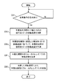
図7はデジタルビデオカメラ100の本露光動作中のフォーカスレンズ113の移動速度であるレンズ移動速度の決定の動作のフローチャートである。図8は、本露光中のフォーカスレンズの移動速度の予測の動作を示す。図8において横軸は時間を示し、縦軸はZ軸の方向での被写体401までの被写体距離L401を示す。図8では、予備露光中及び本露光中に被写体401がデジタルビデオカメラ100からZ軸の正方向に遠ざかっている。   FIG. 7 is a flowchart of an operation for determining a lens moving speed that is the moving speed of the focus lens 113 during the main exposure operation of the digital video camera 100. FIG. 8 shows an operation of predicting the moving speed of the focus lens during the main exposure. In FIG. 8, the horizontal axis indicates time, and the vertical axis indicates the subject distance L401 to the subject 401 in the Z-axis direction. In FIG. 8, the subject 401 is moved away from the digital video camera 100 in the positive direction of the Z axis during the preliminary exposure and the main exposure.

制御部180は合焦指示があったか否かを監視する(ステップS301)。ステップS301において合焦指示があった場合、制御部180は予備露光動作を開始する。予備露光動作において、制御部180は、図8に示すように、CMOSイメージセンサ140に240pの高速フレームレートで被写体401を撮像させてDFD演算を行う。DFD演算の結果に基づいて、制御部180は、予備露光動作中の被写体401のZ軸の方向の移動速度を測定する(ステップS302)。具体的には、制御部180は、1/240秒の間隔でフォーカスレンズ113を移動させつつ、被写体401の被写体画像に基づいてDFD演算を実施する。これにより、制御部180は、1/240秒の期間において被写体401がZ軸の方向に移動した距離を検出することができる。したがって、制御部180は、予備露光期間における被写体401のZ軸の方向の移動速度を算出できる。なお、制御部180は予備露光期間中に240pの高速フレームレートによるDFD演算を数回繰り返すことにより、被写体401のZ軸の方向の移動速度を高精度に算出することができる。   The control unit 180 monitors whether or not an in-focus instruction has been given (step S301). When there is an in-focus instruction in step S301, the control unit 180 starts a preliminary exposure operation. In the preliminary exposure operation, as shown in FIG. 8, the control unit 180 causes the CMOS image sensor 140 to image the subject 401 at a high-speed frame rate of 240p and perform DFD calculation. Based on the result of the DFD calculation, the control unit 180 measures the moving speed in the Z-axis direction of the subject 401 during the preliminary exposure operation (step S302). Specifically, the control unit 180 performs the DFD calculation based on the subject image of the subject 401 while moving the focus lens 113 at intervals of 1/240 seconds. Thus, the control unit 180 can detect the distance that the subject 401 has moved in the Z-axis direction during a period of 1/240 seconds. Therefore, the control unit 180 can calculate the moving speed of the subject 401 in the Z-axis direction during the preliminary exposure period. Note that the control unit 180 can calculate the moving speed of the subject 401 in the Z-axis direction with high accuracy by repeating the DFD calculation at a high frame rate of 240p several times during the preliminary exposure period.

続いて、制御部180は、予備露光動作で得られたZ軸の方向の被写体401の移動速度に基づいて、予備露光動作に続く本露光動作における被写体401のZ軸の方向の移動速度を予測する(ステップS303)。例えば、予備露光動作において、1/240(秒)の期間に被写体距離L401が−12.5センチメートル変化した場合には、制御部180は、予備期間における被写体401のZ軸の方向の移動速度を−3000センチメートル/秒と算出する。制御部180は、計算した予備露光期間における被写体401の移動速度に基づいて、本露光動作における被写体401のZ軸の方向への移動速度も同じく−3000(センチメートル/秒)であると予測する。   Subsequently, the control unit 180 predicts the moving speed in the Z-axis direction of the subject 401 in the main exposure operation following the pre-exposure operation based on the moving speed of the subject 401 in the Z-axis direction obtained in the pre-exposure operation. (Step S303). For example, in the preliminary exposure operation, when the subject distance L401 changes by −12.5 centimeters during a period of 1/240 (seconds), the control unit 180 moves the subject 401 in the Z-axis direction during the preliminary period. Is calculated to be −3000 centimeter / second. Based on the calculated moving speed of the subject 401 during the pre-exposure period, the control unit 180 also predicts that the moving speed of the subject 401 in the Z-axis direction in the main exposure operation is also −3000 (centimeter / second). .

本露光動作における本露光期間が、例えば、1/60(秒)である場合には、制御部180は、本露光動作の1/60(秒)の本露光期間において被写体401は−50(センチメートル)(=−3000(センチメートル/秒)×1/60(秒))の距離を移動すると予測できる。   When the main exposure period in the main exposure operation is, for example, 1/60 (second), the control unit 180 controls the subject 401 to be −50 (centimeter) in the main exposure period of 1/60 (second) of the main exposure operation. Meter) (= −3000 (centimeter / second) × 1/60 (second)).

続いて、制御部180は、予測された移動速度に基づいて、フォーカスレンズ113を制御する制御量を決定する。その後制御部180は、本露光期間において、決定した制御量に対応する移動速度で合焦位置Pfを移動させてCMOSイメージセンサ140に被写体像を撮像させる。実施の形態におけるデジタルビデオカメラ100では、制御部180はフォーカスレンズ113を移動させることで合焦位置Pfを移動させる。すなわち、フォーカスレンズ113の上記制御量はフォーカスレンズ113の移動速度であるレンズ移動速度である。制御部180は、本露光動作の本露光期間において被写体が移動すると予測した距離に基づいて、フォーカスレンズ113のレンズ移動速度を決定する(ステップS304)。具体的には、制御部180は、ズームトラッキングカーブを参照して、被写体距離L401が変化したときに、被写体距離L401に対応するフォーカスレンズ113の位置を得る。   Subsequently, the control unit 180 determines a control amount for controlling the focus lens 113 based on the predicted moving speed. Thereafter, the control unit 180 causes the CMOS image sensor 140 to capture the subject image by moving the focus position Pf at a moving speed corresponding to the determined control amount during the main exposure period. In the digital video camera 100 according to the embodiment, the control unit 180 moves the focus position Pf by moving the focus lens 113. That is, the control amount of the focus lens 113 is a lens moving speed that is the moving speed of the focus lens 113. The control unit 180 determines the lens moving speed of the focus lens 113 based on the distance predicted to move the subject during the main exposure period of the main exposure operation (step S304). Specifically, the control unit 180 refers to the zoom tracking curve and obtains the position of the focus lens 113 corresponding to the subject distance L401 when the subject distance L401 changes.

図9はデジタルビデオカメラ100において本露光期間中のフォーカスレンズ113のレンズ移動速度の決定に際して参照するズームトラッキングテーブルを示す。例えば、予備露光動作すなわち予備露光期間が開始した時点での被写体距離L401が3メートルであり、予備露光動作すなわち予備露光期間が終了した時点での被写体距離が2.5メートルである場合には、制御部180は、本露光動作の本露光期間の1/60(秒)において、被写体は−50(センチメートル)(=−3000(センチメートル/秒)× 1/60(秒))の距離を移動すると予測し、本露光動作すなわち本露光期間が終了した時点での被写体距離L401を2.0メートル(=2.5(メートル)−50(センチメートル))と予測する。制御部180は、ズームトラッキングカーブを参照して被写体距離L401に対応するフォーカスレンズ113の位置を取得する。ズームトラッキングカーブに基づいて、2.5メートルと2.0メートルの間の被写体距離L401に対応するフォーカスレンズ113の位置を取得することが可能である場合は、制御部180は、その間の被写体距離L401に対応するフォーカスレンズ113の位置を適宜取得する。例えば、2.5メートルと2.0メートルの間の被写体距離L401として、2.4メートル、2.3メートル、2.2メートル、2.1メートルの被写体距離L401にそれぞれ対応するフォーカスレンズ113の位置を取得できる場合は、フォーカスレンズ113のこれらの位置FP3〜FP6)を取得する。そして、制御部180は、本露光期間における被写体401のZ軸の方向の移動速度を−3000(センチメートル/秒)であると予測しているので、予備露光期間が終了した時点での被写体距離L401の2.5メートルから中間位置2.4メートルまでの被写体401の移動に要する時間を1/300(秒)であると算出できる。同様に、制御部180は、被写体距離L401の2.4メートルから2.3メートルまでの中間位置の間の被写体401の移動に要する時間など、各中間位置の間の被写体401の移動に要する時間も1/300(秒)と算出できる。制御部180は、ズームトラッキングカーブを参照することにより、各中間位置におけるフォーカスレンズ113の位置を取得しているので、制御部180は、各中間位置の間を移動するフォーカスレンズ113のレンズ移動速度を算出することができる。   FIG. 9 shows a zoom tracking table that is referred to when determining the lens moving speed of the focus lens 113 during the main exposure period in the digital video camera 100. For example, when the subject distance L401 at the start of the pre-exposure operation, that is, the pre-exposure period is 3 meters, and the subject distance at the end of the pre-exposure operation, that is, the pre-exposure period is 2.5 meters, The controller 180 determines that the subject has a distance of −50 (centimeter) (= −3000 (centimeter / second) × 1/60 (second)) in 1/60 (second) of the main exposure period of the main exposure operation. The subject distance L401 at the end of the main exposure operation, ie, the main exposure period, is predicted to be 2.0 meters (= 2.5 (meters) −50 (centimeters)). The control unit 180 acquires the position of the focus lens 113 corresponding to the subject distance L401 with reference to the zoom tracking curve. When the position of the focus lens 113 corresponding to the subject distance L401 between 2.5 meters and 2.0 meters can be acquired based on the zoom tracking curve, the control unit 180 determines the subject distance between them. The position of the focus lens 113 corresponding to L401 is appropriately acquired. For example, as the subject distance L401 between 2.5 meters and 2.0 meters, the focus lens 113 corresponding to the subject distance L401 of 2.4 meters, 2.3 meters, 2.2 meters, and 2.1 meters, respectively. If the position can be acquired, these positions FP3 to FP6) of the focus lens 113 are acquired. Then, since the control unit 180 predicts that the moving speed of the subject 401 in the Z-axis direction during the main exposure period is −3000 (centimeter / second), the subject distance at the time when the pre-exposure period ends. The time required for the movement of the subject 401 from L401 of 2.5 meters to the intermediate position of 2.4 meters can be calculated as 1/300 (seconds). Similarly, the control unit 180 takes time required to move the subject 401 between the intermediate positions, such as time required to move the subject 401 between the intermediate positions of the subject distance L401 from 2.4 meters to 2.3 meters. Can also be calculated as 1/300 (seconds). Since the control unit 180 obtains the position of the focus lens 113 at each intermediate position by referring to the zoom tracking curve, the control unit 180 moves the lens movement speed of the focus lens 113 that moves between the intermediate positions. Can be calculated.

制御部180は、算出されたフォーカスレンズ113のレンズ移動速度に基づき、本露光期間中にフォーカスレンズ113を駆動して移動させる(ステップS305)。これにより、本露光動作中においてZ軸の方向に被写体401が移動した場合でも、CMOSイメージセンサ140は被写体401に合焦させた状態を維持したまま被写体像を露光して撮像することができる。   Based on the calculated lens movement speed of the focus lens 113, the control unit 180 drives and moves the focus lens 113 during the main exposure period (step S305). As a result, even when the subject 401 moves in the Z-axis direction during the main exposure operation, the CMOS image sensor 140 can expose and capture the subject image while maintaining the focused state on the subject 401.

〔3.効果等〕
上述のように、実施の形態における撮像装置であるデジタルビデオカメラ100は被写体401を撮像する。デジタルビデオカメラ100は、合焦位置Pfを有して被写体401の被写体像を形成するフォーカスレンズ113と、被写体像を撮像することにより撮像データを生成する撮像センサであるCOMSイメージセンサ140と、フォーカスレンズ113を制御する制御部180とを備える。制御部180は、予備露光期間(第1の露光期間)において被写体像を撮像することによってCOMイメージセンサ140で生成された撮像データに基づき、予備露光期間におけるデジタルビデオカメラ100から被写体401までの距離の変化を検出するように動作する。制御部180は、距離の検出された変化に基づいて、合焦位置Pfを予備露光期間よりも後の本露光期間(第2の露光期間)において移動させる移動速度を制御する制御量を決定するように動作する。さらに、制御部180は、決定した制御量に対応する移動速度で合焦位置を本露光期間において移動させてCOMイメージセンサ140に被写体像を撮像させるように動作する。
[3. Effect etc.)
As described above, the digital video camera 100 that is the imaging apparatus according to the embodiment images the subject 401. The digital video camera 100 includes a focus lens 113 that forms a subject image of the subject 401 with the in-focus position Pf, a COMS image sensor 140 that is an imaging sensor that generates imaging data by capturing the subject image, and a focus. And a control unit 180 that controls the lens 113. The control unit 180 captures the subject image during the pre-exposure period (first exposure period), and based on the imaging data generated by the COM image sensor 140, the distance from the digital video camera 100 to the subject 401 during the pre-exposure period. Operates to detect changes in Based on the detected change in distance, the control unit 180 determines a control amount for controlling the moving speed for moving the in-focus position Pf in the main exposure period (second exposure period) after the preliminary exposure period. To work. Furthermore, the control unit 180 operates so that the COM image sensor 140 captures a subject image by moving the focus position during the main exposure period at a movement speed corresponding to the determined control amount.

制御量はフォーカスレンズ113を移動させるレンズ移動速度であってもよい。この場合には、制御部180は、本露光期間においてフォーカスレンズ113をレンズ移動速度で移動させることで合焦位置Pfを移動させるように動作する。   The control amount may be a lens moving speed for moving the focus lens 113. In this case, the control unit 180 operates to move the focus position Pf by moving the focus lens 113 at the lens moving speed during the main exposure period.

すなわち、上記説明してきたように、実施の形態における撮像装置であるデジタルビデオカメラ100は、フォーカスレンズ113と、フォーカスレンズ113を介して形成された被写体像に対して撮像動作を行うことで撮像データを生成するCMOSイメージセンサ140と、被写体像が示す被写体までの距離の変化を検出する制御部180とを備える。制御部180は、撮像動作にあたって、予備露光期間と、予備露光期間の後に本露光期間とが設定され、予備露光期間において検出した距離の変化に基づいて、本露光期間においてフォーカスレンズ113を移動させるレンズ移動速度を決定し、決定したレンズ移動速度によりフォーカスレンズ113を移動させる。これにより、本露光動作中においてZ方向に被写体が移動したとしても、合焦状態を維持させたまま被写体像を露光することができる。   That is, as described above, the digital video camera 100 that is the imaging device in the embodiment performs imaging operation on the focus lens 113 and the subject image formed via the focus lens 113 to obtain imaging data. And a control unit 180 that detects a change in the distance to the subject indicated by the subject image. In the imaging operation, the control unit 180 sets a pre-exposure period and a main exposure period after the pre-exposure period, and moves the focus lens 113 during the main exposure period based on a change in distance detected during the pre-exposure period. The lens moving speed is determined, and the focus lens 113 is moved according to the determined lens moving speed. Thus, even if the subject moves in the Z direction during the main exposure operation, the subject image can be exposed while maintaining the in-focus state.

また、制御部180は、本露光期間においてCMOSイメージセンサ140により生成された撮像データに基づく画像データを、メモリカード200へ記録する。   In addition, the control unit 180 records image data based on the imaging data generated by the CMOS image sensor 140 during the main exposure period on the memory card 200.

また、レンズ移動速度はフォーカスレンズ113を移動させる移動量と移動方向を含んでもよい。   The lens moving speed may include a moving amount and a moving direction for moving the focus lens 113.

制御部180は、本露光期間においてCOMイメージセンサ140が被写体像を撮像することにより生成した撮像データに基づく画像データを記録媒体へ記録するように動作する。   The control unit 180 operates to record image data based on imaging data generated when the COM image sensor 140 captures a subject image during the main exposure period onto a recording medium.

また、デジタルビデオカメラ100は、距離に対応する距離情報を所定の時間間隔毎に作成する画像処理部160をさらに備えてもよい。この場合には、制御部180は、所定の時間間隔毎に作成された距離情報に基づいて被写体401までの距離の変化を検出するように動作する。   In addition, the digital video camera 100 may further include an image processing unit 160 that creates distance information corresponding to the distance at predetermined time intervals. In this case, the control unit 180 operates so as to detect a change in the distance to the subject 401 based on the distance information created at predetermined time intervals.

また、制御部180は、フォーカスレンズ113が第1の位置と第2の位置にあるときに被写体像を撮像することで第1の撮像データと第2の撮像データとをそれぞれ撮像センサに生成させるように動作する。この場合に、画像処理部160は、第1の撮像データと第2の撮像データとに基づいて距離情報を作成する。   In addition, the control unit 180 causes the imaging sensor to generate the first imaging data and the second imaging data by capturing the subject image when the focus lens 113 is at the first position and the second position, respectively. To work. In this case, the image processing unit 160 creates distance information based on the first imaging data and the second imaging data.

また、画像処理部160は、第1の撮像データと第2の撮像データとからボケ量を算出し、算出したボケ量に基づいて、距離情報を作成してもよい。   The image processing unit 160 may calculate a blur amount from the first imaging data and the second imaging data, and create distance information based on the calculated blur amount.

〔4.他の実施形態〕
以上のように、本出願において開示する技術の例示として、実施の形態1を説明した。しかしながら、本開示における技術は、これに限定されず、適宜、変更、置き換え、付加、省略などを行った実施の形態にも適用可能である。また、上記実施の形態1で説明した各構成要素を組み合わせて、新たな実施の形態とすることも可能である。
[4. Other embodiments]
As described above, the first embodiment has been described as an example of the technique disclosed in the present application. However, the technology in the present disclosure is not limited to this, and can also be applied to an embodiment in which changes, replacements, additions, omissions, and the like are appropriately performed. Moreover, it is also possible to combine each component demonstrated in the said Embodiment 1, and it can also be set as a new embodiment.

そこで、以下、他の実施の形態を例示する。   Therefore, other embodiments will be exemplified below.

図8に示す動作では予備露光期間中及び本露光期間中に、被写体401がデジタルビデオカメラ100からZ軸の方向に遠ざかっていくがこれに限定されない。すなわち、予備露光期間中及び本露光期間中に、被写体401がからZ軸の方向でデジタルビデオカメラ100に近づいてきても、同様の効果が得られる。   In the operation illustrated in FIG. 8, the subject 401 moves away from the digital video camera 100 in the Z-axis direction during the preliminary exposure period and the main exposure period, but the present invention is not limited to this. That is, the same effect can be obtained even if the subject 401 approaches the digital video camera 100 in the Z-axis direction during the preliminary exposure period and the main exposure period.

上記の動作では、制御部180は、本露光期間における被写体401の移動の速度を予備露光期間における被写体401の移動の速度と等しいとして予測するが、これに限定されない。例えば、制御部180は予備露光期間における被写体401の移動の加速度と等しい加速度で被写体401が本露光期間に移動するとして、その加速度から本露光期間での被写体401の位置と移動の速度を予測してもよい。   In the above operation, the control unit 180 predicts that the moving speed of the subject 401 during the main exposure period is equal to the moving speed of the subject 401 during the preliminary exposure period, but is not limited thereto. For example, assuming that the subject 401 moves in the main exposure period at an acceleration equal to the acceleration of movement of the subject 401 in the preliminary exposure period, the control unit 180 predicts the position of the subject 401 and the speed of movement in the main exposure period from the acceleration. May be.

上記の動作では、制御部180は、本露光期間においてフォーカスレンズ113を移動させるが、これに限定されない。例えば、制御部180は、本露光期間において、フォーカスレンズ113を移動させて、同時に、ズームレンズ111を同期して移動させてもよい。フォーカスレンズ113の移動に同期させたズームレンズ111の移動において、制御部180は、Z軸の方向に移動する被写体401の像倍率が維持されるようにズームレンズ111を移動させることができる。これにより、本露光期間においてZ軸の方向に被写体401が移動しても、被写体401の合焦状態及び像倍率を維持させたままCOMSイメージセンサ140は被写体像を露光できる。   In the above operation, the control unit 180 moves the focus lens 113 during the main exposure period, but the present invention is not limited to this. For example, the control unit 180 may move the focus lens 113 and simultaneously move the zoom lens 111 in synchronization during the main exposure period. In the movement of the zoom lens 111 synchronized with the movement of the focus lens 113, the control unit 180 can move the zoom lens 111 so that the image magnification of the subject 401 moving in the Z-axis direction is maintained. Accordingly, even if the subject 401 moves in the Z-axis direction during the main exposure period, the COMS image sensor 140 can expose the subject image while maintaining the focused state and image magnification of the subject 401.

上記の動作では、制御量はフォーカスレンズ113を移動させるレンズ移動速度である。フォーカスレンズ113の移動以外の方法、例えばフォーカスレンズ113の厚み等の形状を変化させて合焦位置Pfを移動させる場合には、制御量はフォーカスレンズ113の形状や厚みである。この場合には、制御部180は、本露光期間においてフォーカスレンズ113の形状や厚みを変えることで合焦位置Pfを移動させるように動作する。   In the above operation, the control amount is the lens moving speed for moving the focus lens 113. In a method other than the movement of the focus lens 113, for example, when the focus position Pf is moved by changing the shape such as the thickness of the focus lens 113, the control amount is the shape or thickness of the focus lens 113. In this case, the control unit 180 operates to move the in-focus position Pf by changing the shape and thickness of the focus lens 113 during the main exposure period.

上記の実施の形態において、点拡がり関数は内部メモリ240に用意されている。本発明はこれに限定されず、点拡がり関数は、例えば画像処理部160内のメモリに用意されていてもよい。また、実施の形態におけるデジタルビデオカメラ100では、16個の点拡がり関数が選択されるが、Depthマップの階調の数に応じて、選択される点拡がり関数の数は16個以上であっても、16個未満であってもよい。   In the above embodiment, the point spread function is prepared in the internal memory 240. The present invention is not limited to this, and the point spread function may be prepared in a memory in the image processing unit 160, for example. In the digital video camera 100 according to the embodiment, 16 point spread functions are selected, but the number of point spread functions to be selected is 16 or more according to the number of gradations of the Depth map. Or less than 16.

実施の形態におけるデジタルビデオカメラ100は非レンズ交換式のデジタルビデオカメラであるが、これに限定されず、レンズ交換式のデジタルビデオカメラであってもよい。   The digital video camera 100 according to the embodiment is a non-lens interchangeable digital video camera, but is not limited thereto, and may be a lens interchangeable digital video camera.

以上のように、本開示における技術の例示として、実施の形態を説明した。そのために、添付図面および詳細な説明を提供した。   As described above, the embodiments have been described as examples of the technology in the present disclosure. For this purpose, the accompanying drawings and detailed description are provided.

したがって、添付図面および詳細な説明に記載された構成要素の中には、課題解決のために必須な構成要素だけでなく、上記技術を例示するために、課題解決のためには必須でない構成要素も含まれ得る。そのため、それらの必須ではない構成要素が添付図面や詳細な説明に記載されていることをもって、直ちに、それらの必須ではない構成要素が必須であるとの認定をするべきではない。   Accordingly, among the components described in the accompanying drawings and the detailed description, not only the components essential for solving the problem, but also the components not essential for solving the problem in order to illustrate the above technique. May also be included. Therefore, it should not be immediately recognized that these non-essential components are essential as those non-essential components are described in the accompanying drawings and detailed description.

また、上述の実施の形態は、本開示における技術を例示するためのものであるから、請求の範囲またはその均等の範囲において種々の変更、置き換え、付加、省略などを行うことができる。   Moreover, since the above-mentioned embodiment is for demonstrating the technique in this indication, a various change, substitution, addition, abbreviation, etc. can be performed in a claim or its equivalent range.

本発明における撮像装置は、デジタルビデオカメラや、デジタルスチルカメラや、カメラ機能付携帯電話や、カメラ機能付スマートフォン等に適用できる。   The imaging apparatus according to the present invention can be applied to a digital video camera, a digital still camera, a mobile phone with a camera function, a smartphone with a camera function, and the like.

100 デジタルビデオカメラ(撮像装置)
110 光学系
113 フォーカスレンズ
114 絞り
120 レンズ駆動部
140 CMOSイメージセンサ(撮像センサ)
160 画像処理部
Pf 合焦位置
180 制御部
100 Digital video camera (imaging device)
DESCRIPTION OF SYMBOLS 110 Optical system 113 Focus lens 114 Aperture 120 Lens drive part 140 CMOS image sensor (imaging sensor)
160 Image processing unit Pf In-focus position 180 Control unit

Claims (4)

被写体を撮像する撮像装置であって、
合焦位置を有して前記被写体の被写体像を形成するフォーカスレンズと、
前記被写体像を撮像することにより撮像データを生成する撮像センサと、
前記フォーカスレンズを制御する制御部と、
を備え、
前記制御部は、
第1の露光期間において前記被写体像を撮像することによって前記撮像センサで生成された撮像データに基づき、前記第1の露光期間よりも後の第2の露光期間における前記フォーカスレンズに対する制御量であって、前記合焦位置の移動速度を制御する制御量を決定し、
前記第2の露光期間において、前記決定した制御量に対応する移動速度で前記合焦位置を移動させながら前記撮像センサに前記被写体像を撮像させる、
ように動作する、撮像装置。
An imaging device for imaging a subject,
A focus lens having a focus position to form a subject image of the subject;
An imaging sensor that generates imaging data by imaging the subject image;
A control unit for controlling the focus lens;
With
The controller is
A control amount for the focus lens in a second exposure period after the first exposure period based on imaging data generated by the imaging sensor by capturing the subject image in the first exposure period. Determining a control amount for controlling the moving speed of the in-focus position,
In the second exposure period, the imaging sensor captures the subject image while moving the focus position at a movement speed corresponding to the determined control amount.
An imaging device that operates as follows.
前記制御量は前記フォーカスレンズを移動させるレンズ移動速度であり、
前記制御部は、前記第2の露光期間において前記フォーカスレンズを前記レンズ移動速度で移動させることで前記合焦位置を移動させるように動作する、請求項1に記載の撮像装置。
The control amount is a lens moving speed for moving the focus lens,
The imaging apparatus according to claim 1, wherein the control unit operates to move the focus position by moving the focus lens at the lens moving speed in the second exposure period.
前記レンズ移動速度は前記フォーカスレンズを移動させる移動量と移動方向を含む、請求項2に記載の撮像装置。 The imaging apparatus according to claim 2, wherein the lens moving speed includes a moving amount and a moving direction for moving the focus lens. 前記制御部は、前記第2の露光期間において前記撮像センサが前記被写体像を撮像することにより生成した撮像データに基づく画像データを記録媒体へ記録する、請求項1から3のいずれか一項に記載の撮像装置。 The said control part records the image data based on the imaging data produced | generated when the said imaging sensor imaged the said to-be-photographed image in the said 2nd exposure period to a recording medium. The imaging device described.
JP2016015007A 2014-03-28 2016-01-29 Imaging device Active JP6089232B2 (en)

Applications Claiming Priority (2)

Application Number Priority Date Filing Date Title
JP2014068189 2014-03-28

Related Parent Applications (1)

Application Number Title Priority Date Filing Date
JP2014165712A Division JP5895270B2 (en) 2014-03-28 2014-08-18 Imaging device

Publications (2)

Publication Number Publication Date
JP2016122199A true JP2016122199A (en) 2016-07-07
JP6089232B2 JP6089232B2 (en) 2017-03-08

Family

ID=56327413

Family Applications (1)

Application Number Title Priority Date Filing Date
JP2016015007A Active JP6089232B2 (en) 2014-03-28 2016-01-29 Imaging device

Country Status (1)

Country Link
JP (1) JP6089232B2 (en)

Cited By (1)

* Cited by examiner, † Cited by third party
Publication number Priority date Publication date Assignee Title
US10785420B2 (en) 2017-07-13 2020-09-22 Panasonic Intellectual Property Management Co., Ltd. Imaging device and camera for minimizing a digital gain value to be multiplied and suppressing noise

Citations (12)

* Cited by examiner, † Cited by third party
Publication number Priority date Publication date Assignee Title
JPH02163717A (en) * 1988-12-16 1990-06-25 Kyocera Corp Automatic focus adjustor
JPH05313059A (en) * 1992-05-11 1993-11-26 Nikon Corp Automatic focus adjusting device
JPH0868934A (en) * 1994-08-31 1996-03-12 Nikon Corp Automatic focusing device
JP2005215373A (en) * 2004-01-30 2005-08-11 Konica Minolta Photo Imaging Inc Imaging apparatus
JP2008052225A (en) * 2006-08-28 2008-03-06 Olympus Imaging Corp Camera, focus control method, and program
JP2010177741A (en) * 2009-01-27 2010-08-12 Olympus Corp Image capturing apparatus
JP2011015163A (en) * 2009-07-01 2011-01-20 Olympus Corp Imaging apparatus
JP2013044844A (en) * 2011-08-23 2013-03-04 Panasonic Corp Image processing device and image processing method
WO2013136815A1 (en) * 2012-03-15 2013-09-19 パナソニック株式会社 Auto-focusing device and image pickup device
JP2014002370A (en) * 2012-05-21 2014-01-09 Canon Inc Autofocus adjustment unit, lens device having the same, and imaging device
JP2014002283A (en) * 2012-06-19 2014-01-09 Canon Inc Focus adjustment device and control method therefor
JP2014145867A (en) * 2013-01-29 2014-08-14 Olympus Corp Imaging device and imaging method

Patent Citations (12)

* Cited by examiner, † Cited by third party
Publication number Priority date Publication date Assignee Title
JPH02163717A (en) * 1988-12-16 1990-06-25 Kyocera Corp Automatic focus adjustor
JPH05313059A (en) * 1992-05-11 1993-11-26 Nikon Corp Automatic focus adjusting device
JPH0868934A (en) * 1994-08-31 1996-03-12 Nikon Corp Automatic focusing device
JP2005215373A (en) * 2004-01-30 2005-08-11 Konica Minolta Photo Imaging Inc Imaging apparatus
JP2008052225A (en) * 2006-08-28 2008-03-06 Olympus Imaging Corp Camera, focus control method, and program
JP2010177741A (en) * 2009-01-27 2010-08-12 Olympus Corp Image capturing apparatus
JP2011015163A (en) * 2009-07-01 2011-01-20 Olympus Corp Imaging apparatus
JP2013044844A (en) * 2011-08-23 2013-03-04 Panasonic Corp Image processing device and image processing method
WO2013136815A1 (en) * 2012-03-15 2013-09-19 パナソニック株式会社 Auto-focusing device and image pickup device
JP2014002370A (en) * 2012-05-21 2014-01-09 Canon Inc Autofocus adjustment unit, lens device having the same, and imaging device
JP2014002283A (en) * 2012-06-19 2014-01-09 Canon Inc Focus adjustment device and control method therefor
JP2014145867A (en) * 2013-01-29 2014-08-14 Olympus Corp Imaging device and imaging method

Cited By (1)

* Cited by examiner, † Cited by third party
Publication number Priority date Publication date Assignee Title
US10785420B2 (en) 2017-07-13 2020-09-22 Panasonic Intellectual Property Management Co., Ltd. Imaging device and camera for minimizing a digital gain value to be multiplied and suppressing noise

Also Published As

Publication number Publication date
JP6089232B2 (en) 2017-03-08

Similar Documents

Publication Publication Date Title
JP5895270B2 (en) Imaging device
JP5866493B2 (en) Imaging device
JP6405531B2 (en) Imaging device
JP5237721B2 (en) Imaging device
KR20150074641A (en) Auto focus adjusting method and auto focus adjusting apparatus
JP2019092119A (en) Imaging device, lens device, and control method thereof
JP2016143022A (en) Imaging device and imaging method
JP6357646B2 (en) Imaging device
JP6326631B2 (en) Imaging device
JP6432038B2 (en) Imaging device
US10917556B2 (en) Imaging apparatus
JP6089232B2 (en) Imaging device
JP5866537B2 (en) Imaging device
JP2016218106A (en) Imaging device
JP2014138378A (en) Image pickup device, control method thereof, and control program thereof
JP2015012577A (en) Imaging apparatus, imaging method, and program
WO2021065065A1 (en) Imaging device
US10681274B2 (en) Imaging apparatus and control method thereof
JP2008026801A (en) Optical device and control method thereof
JP2016072968A (en) Imaging apparatus and imaging method
JPWO2015182021A1 (en) Imaging control apparatus, imaging apparatus, and imaging control method
JP2014123069A (en) Image capturing device and control method therefor

Legal Events

Date Code Title Description
RD01 Notification of change of attorney

Free format text: JAPANESE INTERMEDIATE CODE: A7421

Effective date: 20160525

A131 Notification of reasons for refusal

Free format text: JAPANESE INTERMEDIATE CODE: A131

Effective date: 20160628

A131 Notification of reasons for refusal

Free format text: JAPANESE INTERMEDIATE CODE: A131

Effective date: 20160906

A521 Request for written amendment filed

Free format text: JAPANESE INTERMEDIATE CODE: A523

Effective date: 20161102

TRDD Decision of grant or rejection written
A01 Written decision to grant a patent or to grant a registration (utility model)

Free format text: JAPANESE INTERMEDIATE CODE: A01

Effective date: 20161227

A61 First payment of annual fees (during grant procedure)

Free format text: JAPANESE INTERMEDIATE CODE: A61

Effective date: 20170109

R151 Written notification of patent or utility model registration

Ref document number: 6089232

Country of ref document: JP

Free format text: JAPANESE INTERMEDIATE CODE: R151