JP2016114799A - Zoom lens barrel and imaging device - Google Patents
Zoom lens barrel and imaging device Download PDFInfo
- Publication number
- JP2016114799A JP2016114799A JP2014253673A JP2014253673A JP2016114799A JP 2016114799 A JP2016114799 A JP 2016114799A JP 2014253673 A JP2014253673 A JP 2014253673A JP 2014253673 A JP2014253673 A JP 2014253673A JP 2016114799 A JP2016114799 A JP 2016114799A
- Authority
- JP
- Japan
- Prior art keywords
- cam
- optical axis
- lens barrel
- zoom lens
- cam follower
- Prior art date
- Legal status (The legal status is an assumption and is not a legal conclusion. Google has not performed a legal analysis and makes no representation as to the accuracy of the status listed.)
- Pending
Links
Images


Classifications
-
- G—PHYSICS
- G02—OPTICS
- G02B—OPTICAL ELEMENTS, SYSTEMS OR APPARATUS
- G02B7/00—Mountings, adjusting means, or light-tight connections, for optical elements
- G02B7/02—Mountings, adjusting means, or light-tight connections, for optical elements for lenses
- G02B7/04—Mountings, adjusting means, or light-tight connections, for optical elements for lenses with mechanism for focusing or varying magnification
- G02B7/10—Mountings, adjusting means, or light-tight connections, for optical elements for lenses with mechanism for focusing or varying magnification by relative axial movement of several lenses, e.g. of varifocal objective lens
Abstract
Description
本発明は、ズームレンズ鏡胴及び撮像装置に関する。 The present invention relates to a zoom lens barrel and an imaging apparatus.
従来のズームレンズ鏡胴において、筒部材に形成されたカム溝に、レンズ群を保持するレンズ枠に設けたカムピンを係合させ、筒部材を回転させることで、レンズ枠と共にレンズ群を光軸方向に移動させ、ズーム機能を実現するようになっているものがある。ところで、このような構成を有するズームレンズ鏡胴をデジタルカメラなどの撮像装置に組み付けた状態、もしくは単体で、誤って落下させたり机などにぶつけたような場合、比較的重量のあるレンズ群がレンズ枠毎慣性で移動し、それによりカム溝にカムピンが食い込んだり、カム溝から脱落したりする恐れがある。 In a conventional zoom lens barrel, a cam groove provided in a lens frame that holds a lens group is engaged with a cam groove formed in the cylindrical member, and the lens member is rotated along with the optical axis by rotating the cylindrical member. There are some which are moved in the direction to realize the zoom function. By the way, when a zoom lens barrel having such a configuration is assembled in an imaging device such as a digital camera, or when it is alone and accidentally dropped or hit a desk, a relatively heavy lens group is formed. Each lens frame moves with inertia, which may cause the cam pin to bite into the cam groove or fall off the cam groove.
このような不具合を解消するために、特許文献1に示すレンズ鏡胴では、駆動カム環に二種類のカム溝部を設け、更にレンズ群を保持するレンズ枠(鏡筒)に設けた第1及び第2のカムピンをそれぞれ対応させている。この二種類のカム溝部のうち一方のカム溝部は、駆動用カムピンに対して隙間のない嵌合状態した駆動用カム溝部であり、鏡筒を光軸方向に移動させる機能を有している。一方、他方のカム溝部は、衝撃吸収用カムピンに対して隙間ある状態となっている耐衝撃用カム溝部であって、このレンズ鏡胴に衝撃力が付与されたときに両者が当接して衝撃を分散するように機能し、これにより駆動用カム溝部からの駆動用カムピンの脱落や、駆動用カム溝部への駆動用カムピンの食い込み等を防止するようになっている。
In order to eliminate such problems, in the lens barrel shown in
ところで、特許文献1に示すレンズ鏡胴では、第1及び第2のカムピンを光軸方向に沿って近接配置している。ここで、落下等によってレンズ鏡胴に衝撃力が付与されたとき、レンズ枠に生じる慣性力は、一般的には光軸方向成分と及び光軸方向に交差する方向成分とに分解できる。しかるに、光軸方向に交差する方向成分の慣性力は、レンズ枠に設けた駆動用カムピンを中心としたモーメントを発生させるが、かかるモーメントを衝撃吸収用カムピンで受ける場合、第1のカムピンと第2のカムピンとの配置スパンが短いために、過大な応力が衝撃吸収用カムピンに作用して、カム溝部の破損等を招く恐れがある。これに対し、第1のカムピンと第2のカムピンとの配置スパンを広げれば、ある程度大きなモーメントに抗することができるようにはなるが、その分レンズ枠が大型化するという問題がある。
By the way, in the lens barrel shown in
本発明は、上述の課題を解決することを目的としたものであり、レンズ枠の小型化を図りつつも、耐衝撃性に優れたズームレンズ鏡胴及びそれを用いた撮像装置を提供することを目的とする。 An object of the present invention is to solve the above-described problems, and to provide a zoom lens barrel excellent in impact resistance while reducing the size of a lens frame, and an imaging device using the same. With the goal.
請求項1に記載のズームレンズ鏡胴は、複数のレンズ群のいずれか1群以上を光軸方向に移動させるズームレンズ鏡胴であって、
第1のカム溝と第2のカム溝を形成した、回転可能な筒部材と、
レンズ群を保持し、前記筒部材に対して光軸方向に移動可能なレンズ枠と、
前記レンズ枠を光軸方向に案内するガイド部材と、を有し、
前記レンズ枠には、前記第1のカム溝に当接係合し相対的に摺動可能となっている第1のカムピンと、前記第2のカム溝に沿って移動する第2のカムピンとが設けられており、
前記筒部材の回転に応じて、前記第1のカムピンが前記第1のカム溝に対して摺動することにより、前記レンズ枠が光軸方向に付勢されるようになっており、
前記ズームレンズ鏡胴に衝撃力が付与されたとき、前記第2のピンが前記第2のカム溝に接して力を受けるようになっており、
前記ズームレンズ鏡胴を光軸方向に見たときに、前記第2のカムピンは、前記第1のカムピンに対して、光軸を挟んで反対側に配置されており、
前記ガイド部材は、前記レンズ枠に相対移動可能に係合し、且つ光軸方向に沿って延在するメインガイドシャフト及びサブガイドシャフトであることを特徴とする。
The zoom lens barrel according to
A rotatable cylindrical member formed with a first cam groove and a second cam groove;
A lens frame that holds the lens group and is movable in the optical axis direction with respect to the cylindrical member;
A guide member for guiding the lens frame in the optical axis direction,
The lens frame includes a first cam pin that comes into contact with and engages with the first cam groove, and a second cam pin that moves along the second cam groove. Is provided,
The lens frame is urged in the optical axis direction by sliding the first cam pin with respect to the first cam groove according to the rotation of the cylindrical member,
When an impact force is applied to the zoom lens barrel, the second pin comes into contact with the second cam groove and receives a force;
When the zoom lens barrel is viewed in the optical axis direction, the second cam pin is disposed on the opposite side of the first cam pin across the optical axis,
The guide member is a main guide shaft and a sub guide shaft that engage with the lens frame so as to be relatively movable and extend along the optical axis direction.
本発明によれば、前記ズームレンズ鏡胴を光軸方向に見たときに、前記第2のカムピンが、前記第1のカムピンに対して、光軸を挟んで反対側に配置されているので、前記レンズ枠を小型化しつつも前記カムピンの配置スパンを大きく確保することができ、それにより落下等によって前記レンズ鏡胴に衝撃力が付与され、前記レンズ枠に生じた慣性力に起因する過大なモーメントを受けた際に、大きなスパンでモーメント荷重を受けることで、前記カムピンと前記カム溝との間に作用する応力を低く抑えることができ、これにより耐衝撃吸収性を向上させることができる。又、前記第1のカムピンに対し、前記第2のカムピンは周方向に離れて配置されているので、前記カムピンのスパンを大きく確保する為に、前記レンズ枠を光軸方向に延長する必要がなく小型化に貢献する。又、前記ガイド部材は、前記レンズ枠に相対移動可能に係合し、且つ光軸方向に沿って延在するメインガイドシャフト及びサブガイドシャフトであるので、前記レンズ枠を光軸方向にスムーズに移動させることができる。尚、「光軸を挟んで反対側に配置」とは、前記第1のカムピンの中心から光軸に下ろした垂線に直交する直交面を境界として前記レンズ枠を二分したときに、前記第2のカムピンが前記第1のカムピンに対して境界を挟んで異なる側に配置されていることをいう。但し、前記第1のカムピンの中心から光軸に下ろした垂線と、前記第2のカムピンの中心から光軸に下ろした垂線とのなす角度が、光軸方向から見て120°〜180°の範囲にあると更に好ましい。 According to the present invention, when the zoom lens barrel is viewed in the optical axis direction, the second cam pin is disposed on the opposite side of the first cam pin across the optical axis. The cam frame can have a large arrangement span while reducing the size of the lens frame, so that an impact force is applied to the lens barrel by dropping or the like, resulting in an excessive force caused by the inertial force generated in the lens frame. When receiving a moment, the stress acting between the cam pin and the cam groove can be kept low by receiving a moment load with a large span, thereby improving impact resistance. . Further, since the second cam pin is arranged in the circumferential direction away from the first cam pin, it is necessary to extend the lens frame in the optical axis direction in order to ensure a large span of the cam pin. Contributes to downsizing. Further, since the guide member is a main guide shaft and a sub guide shaft that are movably engaged with the lens frame and extend along the optical axis direction, the lens frame can be smoothly moved in the optical axis direction. Can be moved. Note that “arranged on the opposite side across the optical axis” means that the second frame is divided into two when the lens frame is bisected with an orthogonal plane perpendicular to a perpendicular line extending from the center of the first cam pin to the optical axis. The cam pins are arranged on different sides with respect to the first cam pin across the boundary. However, an angle formed between a perpendicular line extending from the center of the first cam pin to the optical axis and a perpendicular line extending from the center of the second cam pin to the optical axis is 120 ° to 180 ° when viewed from the optical axis direction. More preferably, it is in the range.
請求項2に記載の撮像装置は、請求項1に記載のズームレンズ鏡胴を有することを特徴とする。 An imaging apparatus according to a second aspect includes the zoom lens barrel according to the first aspect.
本発明によれば、レンズ枠の小型化を図りつつも、耐衝撃吸収性に優れたズームレンズ鏡胴及びそれを用いた撮像装置を提供することができる。 According to the present invention, it is possible to provide a zoom lens barrel excellent in shock resistance absorption and an imaging apparatus using the same while reducing the size of the lens frame.
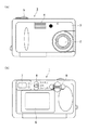
以下、本発明の実施の形態を、図面を参照して説明する。図1は、本実施の形態に係るズームレンズ鏡胴を備えた撮像装置の一例であるデジタルカメラの外観図である。図1(a)は、デジタルカメラ1の前面図であり、図1(b)は背面図である。
Hereinafter, embodiments of the present invention will be described with reference to the drawings. FIG. 1 is an external view of a digital camera that is an example of an imaging apparatus including a zoom lens barrel according to the present embodiment. FIG. 1A is a front view of the
図1に示す様に、デジタルカメラ1は、ズームレンズ鏡胴と撮像素子を有する撮像部2、及び、カメラ本体部3よりなる。
As shown in FIG. 1, the
撮像部2は、ズーム動作可能なズームレンズ鏡胴及びCCD等の固体撮像素子からなり、ズームレンズ鏡胴を介して結像された被写体像を固体撮像素子で画像信号に変換できる。
The
カメラ本体部3は、LCD(Liquid Crystal Display;液晶表示素子)からなるLCD表示部6、EVF(Electronic View Finder;電子ビューファインダ)7、デジタルカメラ1を図示しないパーソナルコンピュータに接続する外部接続端子を有しており、撮像部2で取り込まれた画像信号に所定の信号処理を施し、LCD表示部6やEVF7への画像表示、不図示のメモリカードなどの記録媒体への画像記録、あるいはパーソナルコンピュータへの画像の転送といった処理を行う。
The camera body unit 3 includes an
カメラ本体部3の前面には、上部適所にフラッシュ発光部4が設けられている。また、カメラ本体部3の背面には撮影画像の表示や記録画像の再生表示を行うLCD表示部6とEVF7が設けられている。
On the front surface of the camera body 3, a flash
カメラ本体部3の上面には、シャッタボタン5と、シャッタボタン5の近くに「記録モード」と「再生モード」とを切換設定する、不図示の撮影モード切換スイッチが設けられている。記録モードは、撮影待機状態から露光制御のプロセスを経て撮影にいたる写真撮影を行うモードであり、再生モードは、メモリカードに記録された撮影画像をLCD表示部6やEVF7に再生表示するモードである。
On the upper surface of the camera body 3, there are provided a
カメラ本体部3の背面には、再生画像のコマ送りや、撮影時にズーム操作を行うための再生コマ送りスイッチ/ズームスイッチ9が設けられている。再生コマ送りスイッチ/ズームスイッチ9における再生画像のコマ送りとは、カメラを再生モードに設定しメモリカード13に記録された画像をコマ番号とともにLCD表示部6に順次表示する様にしたものである。なお、LCD表示部6への画像表示を昇順方向(撮影順の方向)若しくは降順方向(撮影順と逆の方向)に変更指示することも可能である。また、撮影時のズーム操作は、再生コマ送りスイッチ/ズームスイッチ9を操作することにより、ズームレンズである撮像光学系をテレ方向若しくはワイド方向に変倍させる。
On the back surface of the camera body 3, a playback frame advance switch /
さらに、カメラ本体部3の背面には、画像表示を行うためのLCD表示部6とEVF7とを選択するEVF切換スイッチ8が設けられている。
Further, an EVF changeover switch 8 for selecting an
また、カメラ本体部3の底面内部には、デジタルカメラ1の動作用電源としての電池(図示せず)が設けられている。
In addition, a battery (not shown) as a power source for operating the
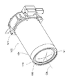
図2は、本実施の形態にかかるズームレンズ鏡胴(レンズ鏡胴ともいう)100の斜視図である。図3は、本実施の形態にかかるズームレンズ鏡胴100の光軸方向断面図である。本実施の形態にかかるズームレンズ鏡胴100を、5群構成のズームレンズを例にして説明する。ズームレンズ鏡胴100は、物体側から順に,レンズL1,L2,L3からなる第1レンズ群G1と、レンズL4,L5,L6,L7からなる第2レンズ群G2と、可変絞り羽根BRを有するシャッタ装置SH、固定レンズL8,L9,L10及び調整レンズL11,L12からなる第3レンズ群G3と、レンズL13からなる第4レンズ群G4と、レンズL14からなる第5レンズ群G5とから構成されている。本実施の形態では、第5レンズ群G5が固定されており、第1レンズ群G1、第2レンズ群G2、第3レンズ群G3、第4レンズ群G4は、互いの群間距離を変化させながら光軸OAの方向に移動してズーミングを行うようになっている。また、第4レンズ群G4は独立して光軸OAの方向に移動してフォーカシングも行うようになっている。第3レンズ群G3の一部となるシャッタ装置SHは、可変絞り羽根BRを駆動することで、任意の開口径の絞りを形成できるようになっている。
FIG. 2 is a perspective view of a zoom lens barrel (also referred to as a lens barrel) 100 according to the present embodiment. FIG. 3 is a cross-sectional view in the optical axis direction of the
図3を参照して、カメラ本体部3に固定される地板101は、中央に円筒部101aを形成しており、その内周に第5レンズ群G5を保持している。レンズ群G1〜G5を通過し、円筒部101a内を通過した被写体光は、カメラ本体部3に取り付けられた固体撮像素子の撮像面に結像されるようになっている。
Referring to FIG. 3, the
地板101の物体側に、固定筒102の端部が同軸に固定されている。固定筒102の周囲には、回転可能にカム筒103が取り付けられており、物体側端部近傍に形成された円周溝103aに、それに対応して固定筒102に形成された突起102aが係合しており、これによりカム筒103は固定筒102に対して光軸方向移動が規制され、回転のみ可能となっている。カム筒103の像側端外周には、ギヤ103bが形成されており、不図示のモータのピニオンが噛合している。
The end of the fixed
固定筒102の物体側端外周には、ピン(図3の断面では不図示)が径方向外方に突出するように形成されている。一方、カム筒103の周囲に配置された直進筒104の内周には,光軸OA方向に延在するように直進溝(図3の断面では不図示)が形成されており、ここに固定筒102の外周から突出したピンが係合している。よって、直進筒104は、固定筒102により回転を規制され、光軸方向にのみ移動可能となっている。直進筒104の物体側端部には、ドーナッツ板状の遮光板106が固定されている。
A pin (not shown in the cross section of FIG. 3) is formed on the outer periphery of the fixed
カム筒103の外周には、第1カム溝103cが形成されており、ここに直進筒104の像側端近傍内周に設けられた第1カムフォロワ104bが係合している。又、カム筒103の内周には、2Aカム溝103d、2Bカム溝103hが形成され、これらに対応して、第2レンズ群G2を保持する第2ホルダ107の外周に、2Aカムフォロワ107a、2Bカムフォロワ107dが設けられている。
A
第2カムフォロワ107aは、その内方端が第2ホルダ107に形成された孔107b内に挿入されており、孔107b内に配置されたバネ部材107cにより径方向外側に押し出されるように付勢されている。一方、2Bカムフォロワ107dは、孔107bに対して光軸方向に離間して第2ホルダ107に形成された孔107e内に固定配置されている。2Aカム溝103dに対して、2Aカムフォロワ107aが係合しているが、2Bカム溝103hに対して、2Bカムフォロワ107dは、隙間を開けた状態で進入している。第4レンズ群G4は、第4ホルダ109により保持されている。尚、第2ホルダ107,第4ホルダ109は、図3では不図示のガイドシャフトにより回転を規制されて、光軸方向に案内されて移動可能となっている。第3ホルダ108に関しては、以下に説明する。
The inner end of the
図4は、第3ホルダ(レンズ枠)108の斜視図である。図5は、図3の構成をV-V線の位置で切断して矢印方向に見た断面図である。図6は、図5のズームレンズ鏡胴の一部をVI-VI線の位置で切断して矢印方向に見た断面図である。図7は、別な方向から見た断面図である。図8は、3Aカム溝103e、3Bカム溝103f、3Cカム溝103gのカム線図であり、2Aカム溝103d、2Bカム溝103hとともに示している。
FIG. 4 is a perspective view of the third holder (lens frame) 108. FIG. 5 is a cross-sectional view of the configuration of FIG. 3 taken along the line V-V and viewed in the direction of the arrow. 6 is a cross-sectional view of a part of the zoom lens barrel of FIG. 5 taken along the line VI-VI and viewed in the direction of the arrow. FIG. 7 is a cross-sectional view seen from another direction. FIG. 8 is a cam diagram of the
図2,図8に示すように、カム筒103の内周には3Aカム溝103e、3Bカム溝103fが並行するように形成され、それらと離間する位置に、3Cカム溝103gが形成されており、更に2Aカム溝103d、2Bカム溝103hが並行するように形成されている。カム筒103に包囲された第3ホルダ108は、第3レンズ群G3の固定レンズL8,L9,L10を保持している。図4に示すように、第3ホルダ108の外周に設けた3Aカムフォロワ(第1のカムピン)108a、3Bカムフォロワ(第2のカムピン)108m、3Cカムフォロワ(第3のカムピン)108nが、それぞれ光軸直交方向に向いて形成されている。
2 and 8, a
図3,図5に示すように、3Aカムフォロワ108aは、その内方端が第3ホルダ108に形成した孔108b内に挿入されており、孔108b内に配置されたバネ部材108hにより、3Aカムフォロワ108aが径方向外側に押し出されるように付勢されている。3Aカムフォロワ108aのテーパ状先端は、固定筒102の周壁に形成された光軸方向に長いスリット102cを通過して3Aカム溝(第1のカム溝)103eに、隙間なく摺動可能に係合している。
As shown in FIGS. 3 and 5, the
又、図5に示す断面で、3Bカムフォロワ108mは、その内方端が第3ホルダ108に形成した孔108p内に挿入されて固定されている。3Bカムフォロワ108mのテーパ状先端は、固定筒102の周壁に形成された光軸方向に長いスリット102cを通過して3Bカム溝(第2のカム溝)103f内に進入しているが、両者は接触しておらず、間に隙間がある。但し、3Bカムフォロワ108mと3Bカム溝103fとは、ズーム動作に支障のない範囲で接触する場合もある。
Further, in the cross section shown in FIG. 5, the
3Aカムフォロワ108aの中心から光軸OAに下ろした垂線N1に直交し且つ光軸OAを通る面VP(図5では紙面垂直方向に延在)に対して、3Bカムフォロワ108mは、3Aカムフォロワ108aと反対側に配置されている。更に具体的には、図5に示す断面において、3Aカムフォロワ108aの中心から光軸OAに下ろした垂線N1と、3Bカムフォロワ108mの中心から光軸OAに下ろした垂線N2とのなす角θは、120°〜180°であると好ましい。尚、3Aカムフォロワ108aと3Bカムフォロワ108mは光軸方向にシフトして配置されているが、光軸方向に同じ位置に設けられていても良い。
The
図3,5に示すように、3Cカムフォロワ108nは、3Aカムフォロワ108aに対して光軸方向に隣接して配置され、その内方端が第3ホルダ108に形成した孔108qに挿入されている。3Cカムフォロワ108nのテーパ状先端は、固定筒102の周壁に形成された光軸方向に長いスリット102cを通過して3Cカム溝(第3のカム溝)103g内に進入しているが、両者は接触しておらず、間に隙間がある。但し、3Cカムフォロワ108nと3Cカム溝103gとは、ズーム動作に支障のない範囲で接触する場合もある。
As shown in FIGS. 3 and 5, the
固定枠としての第3ホルダ108は、固定レンズL8,L9,L10を保持する円筒部108dと、円筒部108dから径方向に延在するフランジ部108fとから一体的に形成されている。フランジ部108fの像側面(第5ホルダ118に対向する面)には、磁石MG1、MG2(図5参照)が固定配置されている。
The
図5を参照して、可動枠としての第5ホルダ118の物体側面(第3ホルダ108に対向する面)には、磁石MG1、MG2にそれぞれ対向するようにしてコイルCL1,CL2が設けられている。コイルCL1,CL2の中央には、それぞれホール素子HE1,HE2が配置されている。コイルCL1,CL2及びホール素子HE1,HE2は、フレキシブルプリント基板115の配線部に接続されている。磁石MG1,MG2,コイルCL1,CL2,フレキシブルプリント基板115により駆動機構を構成する。又、かかる駆動機構と、固定レンズL8,L9,L10と、これらを保持する第3ホルダ108と、調整レンズL11,L12と、これらを保持する第5ホルダ118とでブレ補正ユニットを構成する。
Referring to FIG. 5, coils CL1 and CL2 are provided on the object side surface of the
尚、図5中、MGS2は、第2ホルダ107に摺動可能に嵌合して案内するメインガイドシャフトであり、SGS2は、メインガイドシャフトMGS2に対して光軸OAを挟んで反対側に配置され、第2ホルダ107に摺動可能に嵌合して回転規制するサブガイドシャフトである。又、MGS3は、第3ホルダ108に摺動可能に嵌合して案内するメインガイドシャフトであり、MGS4は、第4ホルダ109に摺動可能に嵌合して案内するメインガイドシャフトであり、SGS3は、メインガイドシャフトMGS3,MGS4に対して光軸OAを挟んで反対側に配置され、第3ホルダ108と第4ホルダ109に摺動可能に嵌合して共通に回転規制するサブガイドシャフトである。メインガイドシャフトMGS3,MGS4は、モータ111に近い側に配置されると好ましい。メインガイドシャフトMGS3とサブガイドシャフトMGS2とでガイド部材を構成する。
In FIG. 5, MGS2 is a main guide shaft that is slidably fitted and guided to the
図6において、第3ホルダ108の像側面には、磁石MG1,MG2を挟むようにして円形凹部108gが3カ所形成されており、その内部には転動体であるボールBLがそれぞれ転動可能に配置されている。また、ボールは球形であることが好ましく、材料としては磁石に吸着されないセラミックやSUSが好ましい。
In FIG. 6, three
図6に示すように組み付けた状態では、ボールBLは、第5ホルダ118の物体側面に当接するようになっている。第3ホルダ108の外周から突き出した3本のアーム108cと、第5ホルダ118の外周から突き出した3本のアーム118aとに、付勢部材であるコイルスプリングCSの両端が取り付けられており、コイルスプリングCSの付勢力により、第3ホルダ108と第5ホルダ118とは互いに近接した方向に付勢されている。
In the assembled state as shown in FIG. 6, the ball BL comes into contact with the object side surface of the
このように、コイルスプリングCSによって互いに付勢された第3ホルダ108と第5ホルダ118との間に3つのボールBLを転動可能に配置することで、第3ホルダ108に対して第5ホルダ118を、光軸方向相対位置を固定したまま、光軸直交方向にスムーズに安定して移動させることができる。又、光軸方向に見たときに、3つのボールBLは直角二等辺三角形(但し頂角は90°に限らず70°〜110°の範囲であれば良い)のほぼ頂点に配置されており、その直角二等辺三角形の等辺に重なる位置に、磁石MG1,MG2及びコイルCL1,CL2(図5)がそれぞれ配置されているので、光軸OAを挟んで、この直角二等辺三角形の頂角と反対側における第3ホルダ108及び第5ホルダ118の一部をカットすることが出来、これにより空いたスペースに、メインガイドシャフトMGS3,MGS4、モータ111、3Aカムフォロワ108a等の部品を配置でき、ズームレンズ鏡胴100をより小型化できる。
As described above, the
本実施の形態にかかるブレ補正ユニットの動作を、図5を参照して説明する。不図示の加速度センサにより、デジタルカメラ1がX方向に振れたと判断されると、フレキシブルプリント基板115を介してコイルCL1に通電が行われ、それにより磁石MG1により形成される磁界内にローレンツ力が発生し、これにより第3ホルダ108に対して第5ホルダ118がX方向に移動することで、調整レンズL11,L12がX方向に移動して像振れを補正する。調整レンズL11,L12のX方向移動量は、ホール素子HE1により検出される。
The operation of the shake correction unit according to the present embodiment will be described with reference to FIG. If the acceleration sensor (not shown) determines that the
同様に、不図示の加速度センサにより、デジタルカメラ1がY方向に振れたと判断されると、コイルCL2に通電が行われ、それにより磁石MG2により形成される磁界内にローレンツ力が発生し、これにより第3ホルダ108に対して第5ホルダ118がY方向に移動することで、調整レンズL11,L12がY方向に移動して像振れを補正する。調整レンズL11,L12のY方向移動量は、ホール素子HE2により検出される。
Similarly, if the acceleration sensor (not shown) determines that the
本実施の形態のズーム動作及びフォーカシング動作について説明する。不図示のモータを駆動させることで、カム筒103が回転すると、第1カム溝103cに沿って第1カムフォロワ104bが摺動し、その際に受ける押圧力により直進筒104は光軸方向に移動するようになっている。又、カム筒103が回転すると、第2カム溝103dに沿って2Aカムフォロワ107aが摺動し、その際に受ける押圧力により第2ホルダ107が光軸方向に移動するようになっている。但し、2Bカム溝103hに対して、2Bカムフォロワ107dは当接することなく、それぞれカム溝に沿って移動する。
The zoom operation and focusing operation of this embodiment will be described. When the
更に、カム筒103が回転すると、3Aカム溝103eに沿って3Aカムフォロワ108aが摺動し、その際に受ける押圧力により第3ホルダ108が光軸方向に移動するようになっている。但し、3Bカム溝103f、3Cカム溝103gに対して、3Bカムフォロワ108m、3Cカムフォロワ108nは当接することなく、それぞれカム溝に沿って移動する。シャッタ装置SHと、調整レンズL11,L12を保持する第5ホルダ118は、第3ホルダ108に連結されているので、これらは一体的に光軸方向に移動する。
Further, when the
図7において、取り付け部材110を介して固定筒102に取り付けられたモータ111の回転軸には、ねじ軸112が連結されている。ねじ軸112の他端は、取り付け部材110に設けられた軸受113により回転可能に支持されている。ねじ軸112には、ナット部材114が螺合している。ナット部材114は、第4レンズ群G4を保持する第4ホルダ109に連結されている。モータ111に給電することで、ねじ軸112が回転し、その回転角度に応じてナット部材114が光軸方向に移動するので、それと共に第4ホルダ109が第4レンズ群G4と共に光軸方向に移動して、ズーム移動又はフォーカシングを行うようになっている。
In FIG. 7, a
本実施の形態によれば、ズームレンズ鏡胴100を光軸方向に見たときに、3Bカムフォロワ108mが、3Aカムフォロワ108aに対して、光軸OAを挟んで反対側に配置されているので、第3ホルダ108を小型化しつつもカムフォロワ同士の間隔を大きくすることができ、それにより落下等によってズームレンズ鏡胴100に衝撃力が付与されたときに、第3ホルダ108に生じた慣性力に起因するモーメントを受けた際に、3Bカムフォロワ108mが3Bカム溝103eに接し、3Bカムフォロワ108mと3Aカムフォロワ108aの間の大きなスパンでモーメント荷重を受けることで、カムフォロワとカム溝との間に作用する応力を低く抑えることができ、耐衝撃性を向上させることができる。
According to the present embodiment, when the
更に本実施の形態によれば、3Cカムフォロワ108nが、3Aカムフォロワ108aに対して、光軸方向に沿って配置されているので、落下等によってズームレンズ鏡胴100に光軸方向の衝撃力が付与されたときに、3Cカムフォロワ108nが3Cカム溝103gに接し、これによりカムフォロワとカム溝との間に作用する応力を低く抑えることができ、耐衝撃性を向上させることができる。
Furthermore, according to the present embodiment, since the
本発明は、明細書に記載の実施例に限定されるものではなく、他の実施例・変形例を含むことは、本明細書に記載された実施例や思想から本分野の当業者にとって明らかである。明細書の記載及び実施例は、あくまでも例証を目的としており、本発明の範囲は後述するクレームによって示されている。例えば、3Aカムフォロワ108a、3Bカムフォロワ108m、3Cカムフォロワ108nを120度間隔で周方向に等間隔に配置しても良い。このように、3Aカムフォロワ108a、3Bカムフォロワ108m、3Cカムフォロワ108nを周方向に等間隔に配置することで、ズームレンズ鏡胴に衝撃力が付与されたとき、衝撃力を更に分散させることができる。但し、3Aカムフォロワ108a及び3Bカムフォロワ108mのみを設ける場合、或いは3Cカムフォロワ108nを設ける場合でも、周方向に等間隔に設けなければ、これらに対向するカム溝が、他のカム溝と干渉する恐れが減るので、設計は容易になる。又、第3レンズ群G3は変倍時に光軸方向に固定されていても良い。また、上述の実施の形態においては、5群構成のズームレンズで説明したが、5群構成に限るものでなく、例えば4群構成であっても良い。
The present invention is not limited to the embodiments described in the specification, and other embodiments and modifications are apparent to those skilled in the art from the embodiments and ideas described in the present specification. It is. The description and examples are for illustrative purposes only, and the scope of the invention is indicated by the following claims. For example,
1 デジタルカメラ
2 撮像部
3 カメラ本体部
4 フラッシュ発光部
5 シャッタボタン
6 表示部
7 EVF
8 切換スイッチ
9 ズームスイッチ
13 メモリカード
100 ズームレンズ鏡胴
101 地板
101a 円筒部
102 固定筒
102a 突起
102c スリット
103 カム筒
103a 円周溝
103b ギヤ
103c 第1カム溝
103d 2Aカム溝
103h 2Bカム溝
103e 3Aカム溝
103f 3Bカム溝
103g 3Cカム溝
104 直進筒
104b 第1カムフォロワ
105 第1ホルダ
106 遮光板
107 第2ホルダ
107a 2Aカムフォロワ
107b 孔
107c バネ部材
107d 2Bカムフォロワ
107e 孔
108 第3ホルダ
108a 3Aカムフォロワ
108b 孔
108c アーム
108d 円筒部
108f フランジ部
108g 円形凹部
108h バネ部材
108m 3Bカムフォロワ
108n 3Cカムフォロワ
108p 孔
108q 孔
109 第4ホルダ
110 取り付け部材
111 モータ
112 ねじ軸
113 軸受
114 ナット部材
115 フレキシブルプリント基板
118 第5ホルダ
118a アーム
BL ボール
BR 羽根
CL1,CL2 コイル
CS コイルスプリング
G1-G5 レンズ群
HE1,HE2 ホール素子
L1―L14 レンズ
MG1,MG2 磁石
MGS2、MGS3,MGS4 メインガイドシャフト
OA 光軸
SH シャッタ装置
DESCRIPTION OF
8
Claims (2)
第1のカム溝と第2のカム溝を形成した、回転可能な筒部材と、
レンズ群を保持し、前記筒部材に対して光軸方向に移動可能なレンズ枠と、
前記レンズ枠を光軸方向に案内するガイド部材と、を有し、
前記レンズ枠には、前記第1のカム溝に当接係合し相対的に摺動可能となっている第1のカムピンと、前記第2のカム溝に沿って移動する第2のカムピンとが設けられており、
前記筒部材の回転に応じて、前記第1のカムピンが前記第1のカム溝に対して摺動することにより、前記レンズ枠が光軸方向に付勢されるようになっており、
前記ズームレンズ鏡胴に衝撃力が付与されたとき、前記第2のピンが前記第2のカム溝に接して力を受けるようになっており、
前記ズームレンズ鏡胴を光軸方向に見たときに、前記第2のカムピンは、前記第1のカムピンに対して、光軸を挟んで反対側に配置されており、
前記ガイド部材は、前記レンズ枠に相対移動可能に係合し、且つ光軸方向に沿って延在するメインガイドシャフト及びサブガイドシャフトであることを特徴とするズームレンズ鏡胴。 A zoom lens barrel that moves one or more of a plurality of lens groups in the optical axis direction,
A rotatable cylindrical member formed with a first cam groove and a second cam groove;
A lens frame that holds the lens group and is movable in the optical axis direction with respect to the cylindrical member;
A guide member for guiding the lens frame in the optical axis direction,
The lens frame includes a first cam pin that comes into contact with and engages with the first cam groove, and a second cam pin that moves along the second cam groove. Is provided,
The lens frame is urged in the optical axis direction by sliding the first cam pin with respect to the first cam groove according to the rotation of the cylindrical member,
When an impact force is applied to the zoom lens barrel, the second pin comes into contact with the second cam groove and receives a force;
When the zoom lens barrel is viewed in the optical axis direction, the second cam pin is disposed on the opposite side of the first cam pin across the optical axis,
The zoom lens barrel according to claim 1, wherein the guide member includes a main guide shaft and a sub guide shaft that are engaged with the lens frame so as to be relatively movable and extend along an optical axis direction.
Priority Applications (2)
| Application Number | Priority Date | Filing Date | Title |
|---|---|---|---|
| JP2014253673A JP2016114799A (en) | 2014-12-16 | 2014-12-16 | Zoom lens barrel and imaging device |
| CN201510932922.0A CN105700107A (en) | 2014-12-16 | 2015-12-15 | Variable-focus lens cylinder and shooting device |
Applications Claiming Priority (1)
| Application Number | Priority Date | Filing Date | Title |
|---|---|---|---|
| JP2014253673A JP2016114799A (en) | 2014-12-16 | 2014-12-16 | Zoom lens barrel and imaging device |
Publications (2)
| Publication Number | Publication Date |
|---|---|
| JP2016114799A true JP2016114799A (en) | 2016-06-23 |
| JP2016114799A5 JP2016114799A5 (en) | 2017-12-21 |
Family
ID=56141800
Family Applications (1)
| Application Number | Title | Priority Date | Filing Date |
|---|---|---|---|
| JP2014253673A Pending JP2016114799A (en) | 2014-12-16 | 2014-12-16 | Zoom lens barrel and imaging device |
Country Status (2)
| Country | Link |
|---|---|
| JP (1) | JP2016114799A (en) |
| CN (1) | CN105700107A (en) |
Cited By (4)
| Publication number | Priority date | Publication date | Assignee | Title |
|---|---|---|---|---|
| WO2018139352A1 (en) * | 2017-01-24 | 2018-08-02 | パナソニックIpマネジメント株式会社 | Lens barrel |
| JP2019184853A (en) * | 2018-04-11 | 2019-10-24 | キヤノン株式会社 | Imaging device |
| US11194117B2 (en) | 2017-11-09 | 2021-12-07 | Panasonic Intellectual Property Management Co., Ltd. | Lens barrel |
| JP7446895B2 (en) | 2020-04-07 | 2024-03-11 | キヤノン株式会社 | lens barrel |
Families Citing this family (4)
| Publication number | Priority date | Publication date | Assignee | Title |
|---|---|---|---|---|
| JP6737095B2 (en) * | 2016-09-13 | 2020-08-05 | コニカミノルタ株式会社 | Lens barrel |
| JP7056585B2 (en) * | 2017-06-02 | 2022-04-19 | 株式会社ニコン | Lens barrel and image pickup device |
| CN111580324B (en) | 2020-06-08 | 2022-02-22 | 昆山联滔电子有限公司 | Voice coil motor |
| CN212569247U (en) * | 2020-06-15 | 2021-02-19 | 诚瑞光学(常州)股份有限公司 | Lens module |
Citations (6)
| Publication number | Priority date | Publication date | Assignee | Title |
|---|---|---|---|---|
| JPH11174305A (en) * | 1997-12-10 | 1999-07-02 | Olympus Optical Co Ltd | Zoom lens barrel |
| US20080019028A1 (en) * | 2006-07-18 | 2008-01-24 | Tsung-Li Chen | Impact-resistant barrel assembly for a lens device |
| JP2010072627A (en) * | 2008-08-21 | 2010-04-02 | Nikon Corp | Lens barrel and imaging apparatus |
| JP2011242683A (en) * | 2010-05-20 | 2011-12-01 | Canon Inc | Lens barrel and imaging apparatus having the same |
| JP2013025209A (en) * | 2011-07-25 | 2013-02-04 | Nikon Corp | Lens barrel and imaging device |
| JP2014048450A (en) * | 2012-08-31 | 2014-03-17 | Konica Minolta Inc | Lens barrel |
Family Cites Families (3)
| Publication number | Priority date | Publication date | Assignee | Title |
|---|---|---|---|---|
| JP5498055B2 (en) * | 2009-05-14 | 2014-05-21 | オリンパスイメージング株式会社 | Lens barrel and imaging device |
| JP5293680B2 (en) * | 2010-05-14 | 2013-09-18 | 株式会社ニコン | Lens barrel and imaging device including the same |
| JP5679744B2 (en) * | 2010-09-13 | 2015-03-04 | キヤノン株式会社 | Lens barrel |
-
2014
- 2014-12-16 JP JP2014253673A patent/JP2016114799A/en active Pending
-
2015
- 2015-12-15 CN CN201510932922.0A patent/CN105700107A/en active Pending
Patent Citations (6)
| Publication number | Priority date | Publication date | Assignee | Title |
|---|---|---|---|---|
| JPH11174305A (en) * | 1997-12-10 | 1999-07-02 | Olympus Optical Co Ltd | Zoom lens barrel |
| US20080019028A1 (en) * | 2006-07-18 | 2008-01-24 | Tsung-Li Chen | Impact-resistant barrel assembly for a lens device |
| JP2010072627A (en) * | 2008-08-21 | 2010-04-02 | Nikon Corp | Lens barrel and imaging apparatus |
| JP2011242683A (en) * | 2010-05-20 | 2011-12-01 | Canon Inc | Lens barrel and imaging apparatus having the same |
| JP2013025209A (en) * | 2011-07-25 | 2013-02-04 | Nikon Corp | Lens barrel and imaging device |
| JP2014048450A (en) * | 2012-08-31 | 2014-03-17 | Konica Minolta Inc | Lens barrel |
Cited By (6)
| Publication number | Priority date | Publication date | Assignee | Title |
|---|---|---|---|---|
| WO2018139352A1 (en) * | 2017-01-24 | 2018-08-02 | パナソニックIpマネジメント株式会社 | Lens barrel |
| JPWO2018139352A1 (en) * | 2017-01-24 | 2019-11-07 | パナソニックIpマネジメント株式会社 | Lens barrel |
| US11194117B2 (en) | 2017-11-09 | 2021-12-07 | Panasonic Intellectual Property Management Co., Ltd. | Lens barrel |
| JP2019184853A (en) * | 2018-04-11 | 2019-10-24 | キヤノン株式会社 | Imaging device |
| JP7066492B2 (en) | 2018-04-11 | 2022-05-13 | キヤノン株式会社 | Imaging device |
| JP7446895B2 (en) | 2020-04-07 | 2024-03-11 | キヤノン株式会社 | lens barrel |
Also Published As
| Publication number | Publication date |
|---|---|
| CN105700107A (en) | 2016-06-22 |
Similar Documents
| Publication | Publication Date | Title |
|---|---|---|
| JP2016114799A (en) | Zoom lens barrel and imaging device | |
| JP4830512B2 (en) | Lens barrel and camera | |
| US8564675B2 (en) | Image-shake correction device, lens barrel, and optical apparatus | |
| JP4332583B2 (en) | Lens barrel and imaging device provided with the same | |
| CN103186010A (en) | Optical image stabilizer and lens driving apparatus | |
| JP2011065145A (en) | Optical element driving device and imaging device | |
| JP2007199319A (en) | Lens barrel, camera system, and lens barrel adjusting device | |
| JP2006350157A (en) | Image blur correcting device, lens barrel having the image blur correcting device, and optical equipment | |
| US9703114B2 (en) | Image stabilizer, lens barrel, image pickup apparatus, and optical apparatus | |
| US10247954B2 (en) | Stage apparatus having shake-correction function | |
| TWI483055B (en) | Camera module | |
| JP2015121755A (en) | Image shake correction device, lens device, and imaging device | |
| JP2016061877A (en) | Zoom lens barrel and imaging device | |
| JP2012032526A (en) | Image blur correction device and camera | |
| JP6376801B2 (en) | Image blur correction device, lens barrel, and optical apparatus | |
| JP2007102050A (en) | Lens barrel | |
| JP5544900B2 (en) | Optical apparatus and optical apparatus | |
| JP6811373B2 (en) | Lens barrel | |
| CN116320750A (en) | Vibration isolation device and imaging device | |
| US11644638B2 (en) | Lens apparatus and image pickup apparatus | |
| JP2015028605A (en) | Lens barrel | |
| JP2007017471A (en) | Position detector for detecting position of moving body and lens driving device | |
| JP6648622B2 (en) | Lens barrel and imaging device | |
| JP2014010213A (en) | Lens barrel | |
| KR102597174B1 (en) | sensor shifting module and camera module having the same |
Legal Events
| Date | Code | Title | Description |
|---|---|---|---|
| A521 | Request for written amendment filed |
Free format text: JAPANESE INTERMEDIATE CODE: A523 Effective date: 20171110 |
|
| A621 | Written request for application examination |
Free format text: JAPANESE INTERMEDIATE CODE: A621 Effective date: 20171110 |
|
| A131 | Notification of reasons for refusal |
Free format text: JAPANESE INTERMEDIATE CODE: A131 Effective date: 20180718 |
|
| A977 | Report on retrieval |
Free format text: JAPANESE INTERMEDIATE CODE: A971007 Effective date: 20180718 |
|
| A601 | Written request for extension of time |
Free format text: JAPANESE INTERMEDIATE CODE: A601 Effective date: 20180914 |
|
| A02 | Decision of refusal |
Free format text: JAPANESE INTERMEDIATE CODE: A02 Effective date: 20190201 |