JP2016111167A - Lamination unit - Google Patents
Lamination unit Download PDFInfo
- Publication number
- JP2016111167A JP2016111167A JP2014246442A JP2014246442A JP2016111167A JP 2016111167 A JP2016111167 A JP 2016111167A JP 2014246442 A JP2014246442 A JP 2014246442A JP 2014246442 A JP2014246442 A JP 2014246442A JP 2016111167 A JP2016111167 A JP 2016111167A
- Authority
- JP
- Japan
- Prior art keywords
- main body
- fins
- flow path
- cooler
- metal plates
- Prior art date
- Legal status (The legal status is an assumption and is not a legal conclusion. Google has not performed a legal analysis and makes no representation as to the accuracy of the status listed.)
- Pending
Links
Images


Landscapes
- Inverter Devices (AREA)
- Cooling Or The Like Of Electrical Apparatus (AREA)
- Cooling Or The Like Of Semiconductors Or Solid State Devices (AREA)
Abstract
Description
本発明は、複数のパワーカードと複数の冷却器が積層されている積層ユニットに関する。 The present invention relates to a stacked unit in which a plurality of power cards and a plurality of coolers are stacked.
半導体素子を収容している複数のパワーカードと複数の冷却器が積層されており、少なくとも一つの冷却器の両側にパワーカードが接している積層ユニットが知られている。そのような積層ユニットは、多数の半導体素子を集積して効率よく冷却することができる。そのような積層ユニットは、例えば、電気自動車において走行用モータに電力を供給するインバータに採用されている(例えば特許文献1)。 A stacked unit is known in which a plurality of power cards containing a semiconductor element and a plurality of coolers are stacked, and the power cards are in contact with both sides of at least one cooler. Such a stacked unit can efficiently cool by integrating a large number of semiconductor elements. Such a laminated unit is employed in, for example, an inverter that supplies power to a traveling motor in an electric vehicle (for example, Patent Document 1).
本願の出願人は、特徴ある冷却器を採用した積層ユニットを考案した(特願2014−189299号、2014年9月17日出願、本願出願時は未公開)。その冷却器は、本体と一対の金属板で構成されている。本体は、内部に積層方向と交差する方向に冷媒が流れる流路が形成されている、また、本体には、両側のパワーカードの夫々と対向する面に流路と連通する開口が設けられている。夫々の金属板は夫々の開口を塞いでいる。夫々の金属板は、流路側の面に冷媒の流れ方向に沿って延びている複数のフィンが設けられており、反対側の面がパワーカードに接している。この積層ユニットは、その積層方向に加圧されており、その圧力によって冷却器の本体の両側の開口がガスケットと一対の金属板で封止されている。 The applicant of the present application has devised a laminated unit that employs a characteristic cooler (Japanese Patent Application No. 2014-189299, filed on September 17, 2014, unpublished at the time of application). The cooler is composed of a main body and a pair of metal plates. The main body is formed with a flow path through which the refrigerant flows in a direction crossing the stacking direction, and the main body is provided with an opening that communicates with the flow path on the surface facing each of the power cards on both sides. Yes. Each metal plate closes each opening. Each metal plate is provided with a plurality of fins extending along the flow direction of the refrigerant on the flow path side surface, and the opposite surface is in contact with the power card. This lamination unit is pressurized in the lamination direction, and the opening on both sides of the main body of the cooler is sealed with a gasket and a pair of metal plates by the pressure.
この冷却器は、パワーカードに接する部位に金属板を用いるが、その金属板とは別体の本体は金属以外の材料、例えば樹脂で作ることができる。一方、部品交差等により本体の内部で一方の金属板から延びるフィンの先端と他方の金属板から延びるフィンの先端との間に空隙ができた場合、冷媒はフィンの平坦面同士の間の隙間よりも上記空隙を流れ易いため冷却効率上の損失が増加する虞がある。本明細書は、本願の出願人が考案した上記積層ユニットの冷却器における損失を低減する技術を提供する。 In this cooler, a metal plate is used at a portion in contact with the power card, but the main body separate from the metal plate can be made of a material other than metal, for example, a resin. On the other hand, if there is a gap between the tip of the fin extending from one metal plate and the tip of the fin extending from the other metal plate inside the main body due to the intersection of the parts, the refrigerant is a gap between the flat surfaces of the fins. Since it is easier to flow through the gap, there is a risk that the loss in cooling efficiency will increase. This specification provides the technique which reduces the loss in the cooler of the said lamination | stacking unit which the applicant of this application devised.
本明細書が開示する技術が対象とする積層ユニットは次の通りである。その積層ユニットは、半導体素子を収容している複数のパワーカードと複数の冷却器が積層されているデバイスである。少なくとも一つの冷却器の両側にパワーカードが接している。その少なくとも一つの冷却器は、本体と一対の金属板を備える。本体は、内部に積層方向と交差する方向に冷媒が流れる流路が形成されている。また、本体には、両側のパワーカードの夫々と対向する位置に流路に連通する開口が設けられている。一対の金属板の夫々は、本体の夫々の開口をガスケットを介して塞いでいる。各金属板は、流路側の面に冷媒の流れ方向に沿って延びている複数のフィンが設けられており、反対側の面がパワーカードに接している。そして、積層ユニットはその積層方向に加圧されることによって本体の両側の開口が一対の金属板で封止されている。本明細書が開示する積層ユニットの冷却器の本体には、流路を横断する少なくとも一つのリブが設けられている。その少なくとも一つのリブは、一対の金属板と平行な方向であって冷媒の流れ方向に交差する方向に延びている。また、リブは、流路の対向する内面の一方から他方まで延びている。さらにまた、一対の金属板の夫々が備える複数のフィンの先端同士が流路内で対向しているとともに、夫々の金属板の複数のフィンに、上記したリブが通る切欠が設けられている。その切欠にて上記したリブと複数のフィンとの間に弾性部材が挟まれている。 The laminated units targeted by the technology disclosed in this specification are as follows. The stacked unit is a device in which a plurality of power cards containing semiconductor elements and a plurality of coolers are stacked. A power card is in contact with both sides of at least one cooler. The at least one cooler includes a main body and a pair of metal plates. The main body has a flow path through which the refrigerant flows in a direction intersecting the stacking direction. The main body is provided with an opening communicating with the flow path at a position facing each of the power cards on both sides. Each of the pair of metal plates closes each opening of the main body via a gasket. Each metal plate is provided with a plurality of fins extending along the flow direction of the refrigerant on the flow path side surface, and the opposite surface is in contact with the power card. The laminated unit is pressurized in the laminating direction so that the openings on both sides of the main body are sealed with a pair of metal plates. The main body of the cooler of the laminated unit disclosed in the present specification is provided with at least one rib crossing the flow path. The at least one rib extends in a direction parallel to the pair of metal plates and intersecting the refrigerant flow direction. The rib extends from one of the opposing inner surfaces of the flow path to the other. Furthermore, the tips of the plurality of fins provided in each of the pair of metal plates are opposed to each other in the flow path, and the notches through which the ribs described above are provided are provided in the plurality of fins of each metal plate. An elastic member is sandwiched between the rib and the plurality of fins at the notch.
切欠において、リブと弾性体部材が、一方の金属板から延びるフィンの先端と他方の金属板から延びるフィンの先端との間の空隙を塞ぐ。それゆえ、フィンの先端同士の間を流れていた冷媒は、フィンの平坦面間の隙間へと誘導される。上記の構造によれば、フィンの平坦面に沿って流れる冷媒の量を増やすことができ、冷却効率が向上する。本明細書が開示する技術の詳細とさらなる改良は以下の「発明を実施するための形態」にて説明する。 In the notch, the rib and the elastic member close the gap between the tip of the fin extending from one metal plate and the tip of the fin extending from the other metal plate. Therefore, the refrigerant flowing between the tips of the fins is guided to the gap between the flat surfaces of the fins. According to said structure, the quantity of the refrigerant | coolant which flows along the flat surface of a fin can be increased, and cooling efficiency improves. Details and further improvements of the technology disclosed in this specification will be described in the following “DETAILED DESCRIPTION”.
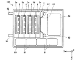
図面を参照して実施例の積層ユニットを説明する。図1に、積層ユニット2の斜視図を示す。実施例の積層ユニット2は、電気自動車に搭載される電力変換器の主要部品である。電力変換器は、バッテリの直流を昇圧する電圧コンバータと、昇圧された直流を交流に変換して走行用モータに供給するインバータを含む。電圧コンバータとインバータは、発熱量の大きい多数のスイッチング素子(半導体素子)を含む。積層ユニット2は、それら多数のスイッチング素子を集約して効率良く冷却するユニットである。
The laminated unit of the embodiment will be described with reference to the drawings. FIG. 1 shows a perspective view of the laminated
図1に示すように、積層ユニット2は、複数のパワーカード5と複数の冷却器3a〜3eが積層されているユニットである。図中のX軸の方向が積層方向に相当する。以降の図でも同様である。
As shown in FIG. 1, the
各パワーカード5の両側に冷却器が接している。3個の冷却器3b〜3dは同じ構造を有しており、冷却器3b〜3dの夫々の両面にパワーカード5が接している。積層方向の両端の冷却器3a、3eは、一方の面だけにパワーカード5が接している。それゆえ、積層方向の両端の冷却器3a、3eは、冷却器3b〜3dと少し異なる構造を有している。しかし、冷却器3a〜3eは、その内部に図中のY軸方向に冷媒が流れる流路を有する点では共通している。詳しくは後述するが、冷却器3a〜3eは、図中のY軸方向の両端に積層方向に貫通する貫通孔を有しており、冷却器3aに設けられた供給管91から供給された冷媒は、一方の貫通孔を通じて積層方向の他端の冷却器3eまで冷媒が行き渡る。冷媒は液体であり、典型的には水あるいはLLC(Long Life Coolant)である。冷媒は各冷却器3a〜3eを通過する間に隣接するパワーカード5から熱を吸収し、他方の貫通孔を通じ、冷却器3aに設けられた排出管92から排出される。
A cooler is in contact with both sides of each
両側にパワーカード5が接している3個の冷却器3b〜3dの一つ、冷却器3bの構造を概説する。冷却器3bは、樹脂製の本体30と一対の金属板13で構成されている。後に詳しく説明するが、本体30は内部を冷媒が通る流路を有しており、パワーカード5と対向する面にその流路と連通する開口が設けられている。一対の金属板13の夫々がガスケットを挟んで夫々の開口を塞いでいる。一対の金属板13と後述するガスケットによって本体30の流路が密閉される。冷却器3c、3dも冷却器3bと同様の構造を有している。冷却器3a、3eは、内部に流路が形成されており、パワーカード5と対向する面に開口が設けられており、その開口が金属板とガスケットで封止されている点は、冷却器3b〜3dと同じである。積層方向の一端に位置する冷却器3aは、積層ユニット2の最外側の面が塞がれているとともに、その面に供給管91と排出管92が設けられている点が冷却器3b〜3dと異なる。積層方向の他端に位置する冷却器3eは、積層ユニット2の最外側の面が塞がれている点が冷却器3b〜3dと異なる。
The structure of the cooler 3b, one of the three
図2は、積層ユニット2を組み込んだ電力変換器100の部品レイアウトを示す平面図である。積層ユニット2は、電力変換器100のハウジング80の内壁と支柱82の間に収容される。積層ユニット2と支柱82の間に板バネ83が挿入される。板バネ83により、積層ユニット2は、積層方向に加圧された状態で保持される。後に詳しく説明するが、積層方向の加圧により、本体30の開口と金属板13の間の水密性が保持される。また、積層方向の加圧により、冷却器3a〜3eとパワーカード5の密着性が高まり、パワーカード5から冷却器3a〜3eへの熱伝達効率が高められている。ハウジング80には、積層ユニット2のほか、コンデンサ素子81、リアクトル84が収容される。幾つかのコンデンサ素子81とリアクトル84は、電圧コンバータの部品であり、残りのコンデンサ素子は、電圧コンバータの出力電流の脈動を抑制する平滑化コンデンサとして使われる。ハウジング80には、その他、パワーカード5が収容しているスイッチング素子を制御するための基板や電流センサなども収容されるがそれらの図示は省略している。
FIG. 2 is a plan view showing a component layout of the
次に、両側にパワーカード5が接している冷却器3b〜3dについて、冷却器3bを説明する。冷却器3c、3dも冷却器3bと同じ構造を有している。冷却器3a、3eの構造の詳細は説明を省略する。
Next, the cooler 3b is demonstrated about the
図3に冷却器3bの分解斜視図を示す。なお、図3には、冷却器3bの積層方向の両側に位置するパワーカード5を仮想線で描いてある。先に述べたように、冷却器3bは、樹脂製の本体30と一対の金属板13a、13b、ガスケット12a、12b、及び、弾性部材33a、33bで構成されている。本体30は内部に冷媒が流れる流路Psが形成されている。本体30には、両側のパワーカード5の夫々と対向する位置に開口32a、32bが設けられている。開口32a、32bは内部の流路Psに通じている。符号93が示しているのは、軽量化のための溝である。図3では隠れて見えないが、本体30の反対側の側面にも軽量化のための溝が設けられている。このように本体30は複雑な形状を有しているが、本体30は樹脂の射出成形で低コストで作ることができる。また、本体30は樹脂で作られているので軽量である。
FIG. 3 shows an exploded perspective view of the cooler 3b. In FIG. 3, the
本体30の一方の開口32aはガスケット12aを挟んで金属板13aで塞がれる。他方の開口32bはガスケット12bを挟んで金属板13bで塞がれる。一対の金属板13a、13bは、本体30を挟んで対向する。金属板13aの流路側を向く面13a1には複数のフィン14aが設けられており、反対側の面13a2はパワーカード5に接する。金属板13bの流路側を向く面13b1には複数のフィン14bが設けられており、反対側の面13b2は別のパワーカード5に接する。金属板13aのフィン14aと金属板13bのフィン14bは、冷媒の流れの中に配置されることになる。パワーカード5の熱は、金属板13a、13bとそれらに設けられたフィン14a、14bを介して冷媒に吸収される。冷却器3bは、その本体30は熱伝導率の高くない樹脂で作られるが、一方の面がパワーカード5に接し他方の面が冷媒に接する部分に金属板13a、13bを備えることで高い冷却性能を確保している。
One
本体30はY軸方向に横長であり、Y軸方向の両端に、積層方向に延びる筒部35が設けられている。筒部35の内側には、積層方向に延びる貫通孔34が形成されている。一方の筒部35aの貫通孔34aから入った冷媒は、流路PsをY軸方向に流れ、他方の筒部35bの貫通孔34bから出ていく。冷媒は図中のY軸方向に流れる。積層ユニット2では、隣接する冷却器の貫通孔同士が連通しており、一方の貫通孔34aを通じて全ての冷却器に冷媒が分配される(図1参照)。また、各冷却器の流路Psを通った冷媒は、他方の貫通孔34bを通じて集合し、排出管92から排出される(図1参照)。
The
複数のフィン14a、14bは、冷媒の流れ方向に沿って延びている。流路Ps内で冷媒は、フィンの平坦面間を流れる間にフィンを通じてパワーカードの熱を吸収する。複数のフィン14aの夫々に切欠15が設けられている。複数のフィン14aの全てが同じ位置に同じ形状の切欠を有しており、それらの切欠がフィンの並び方向に延びる空間を形成する。その空間を後述するリブ31が通る。複数のフィン14bの夫々にも同様に切欠15が設けられている。
The plurality of
本体30の流路Psにリブ31が設けられている。リブ31は、図中のZ軸方向に延びている。即ち、リブ31は、一対の金属板13a、13bと平行に延びているとともに、冷媒の流れ方向(Y軸方向)に交差する方向に延びている。リブ31は、流路Psに面する平行な一対の本体内面37、38をつなぐように設けられている。リブ31の冷媒上流側の縁に弾性部材33aが嵌合しており、冷媒下流側の縁に弾性部材33bが嵌合している。弾性部材33aは、流路Psに面する平行な一対の本体内面37、38の一方から他方に達する長さを有している。別言すれば、弾性部材33a、33bは、流路Psを横断する長さを有している。弾性部材33a、33bは、ガスケット12a、12bと同じ材料で作られている。弾性部材33a、33b、及び、ガスケット12a、12bは、例えばシリコンゴムで作られている。
リブ31と弾性部材33a、33bとフィン14a、14bの関係について説明する。図4は、冷却器3bをZ軸方向の中央にてXY平面でカットした断面図である。冷却器3bは、リブ31を中心にZ軸に対して対象であるので、図4では、リブ31より左側の一部の図示を省略している。
The relationship between the
リブ31は、流路Psの積層方向(X軸方向)の中央に位置する。リブ31は冷媒の流れ方向(Y軸方向)においても本体30の中央に位置する。図4によく示されているように、リブ31は、フィン14a、14bに設けられた切欠15を通っている。弾性部材33aは、リブ31の冷媒流れ方向の上流側の縁を覆っている。弾性部材33bは、リブ31の冷媒流れ方向の下流側の縁を覆っている。弾性部材33a、33bは、いずれも、切欠15にてリブ31とフィン14a、14bの間に挟まれている。
The
一方の金属板13aのフィン14aの先端と他方の金属板13bのフィン14bの先端は、流路Ps内で対向する。ここで、「フィンの先端」とは、金属板の法線方向(図中のX軸方向)におけるフィンの先端を意味する。フィン14aの先端とフィン14bの先端の間にはギャップGが存在する。このギャップGは、次の理由でゼロにすることが難しい。金属板13aはガスケット12aを介して本体30の一方の側面に当接しており、金属板13bはガスケット12bを介して本体30の他方の側面に当接している。先に述べたように、積層ユニット2はその積層方向(即ち図4のX軸方向)に加圧されており、その圧力によって、一対の金属板13a、13bの夫々が、夫々の開口32a、32bを封止している。加圧によるガスケット12a、12bの変形量は個々の冷却器で異なる。また、ガスケット12a、12bが開口32a、32bを封止するのに充分なほどに変形する前にフィン14aの先端とフィン14bの先端が当接してしまうと、金属板13a、13bはそれ以上に両者の間隔を狭めることができなくなり、開口32a、32bの封止が不完全となる虞がある。加圧によるガスケット12a、12bの変形量のばらつきを許容するために、ギャップGはゼロにすることができない。
The tips of the
一方、ギャップGを流れる冷媒はフィンの平坦面に接しないので冷却性能上の無駄が生じる。即ち、冷却効率上の損失が増加する。リブ31と弾性部材33a、33bは、冷媒の流れ方向の一部でギャップGを埋める。これにより、図4の矢印F1、F2が示すように、冷媒はギャップGからフィンの平坦面間の空間へと誘導される。その結果、流路Psを通過する全ての冷媒が少なくともフィンの平坦面の一部に触れることになり、冷却効果が高まる。即ち、冷却効率上の損失が抑制される。なお、切欠15にてフィン14a、14bの先端が弾性部材33a、33bに当接しても、弾性部材33a、33bが変形し、フィン14a、14bの変形は抑えられる。冷却器3c、3dも冷却器3bと同じ構造を有している。
On the other hand, since the refrigerant flowing through the gap G does not come into contact with the flat surface of the fin, waste in cooling performance occurs. That is, the loss on cooling efficiency increases. The
実施例の積層ユニット2は、次の特徴を有する。複数のパワーカード5の夫々は、半導体素子を収容している。その複数のパワーカード5と複数の冷却器3a−3eが一つずつ交互に積層されている。各パワーカード5の両側に冷却器が接している。積層ユニット2の積層方向両端の冷却器(冷却器3aと3e)を除く冷却器(3b−3d)の夫々が、図3に示した構造を有している。
The
実施例で説明した技術に関する留意点を述べる。実施例の冷却器3bは、本体30の冷媒の流れ方向の中央に一つのリブ31を有する。冷却器の本体は複数のリブを有していてもよい。弾性部材33a、33bは、ガスケット12a、12bとともに、射出成形で直接に本体30に形成されるものであってもよい。
Points to be noted regarding the technology described in the embodiments will be described. The
以上、本発明の具体例を詳細に説明したが、これらは例示に過ぎず、特許請求の範囲を限定するものではない。特許請求の範囲に記載の技術には、以上に例示した具体例を様々に変形、変更したものが含まれる。本明細書または図面に説明した技術要素は、単独であるいは各種の組合せによって技術的有用性を発揮するものであり、出願時請求項記載の組合せに限定されるものではない。また、本明細書または図面に例示した技術は複数目的を同時に達成し得るものであり、そのうちの一つの目的を達成すること自体で技術的有用性を持つものである。 Specific examples of the present invention have been described in detail above, but these are merely examples and do not limit the scope of the claims. The technology described in the claims includes various modifications and changes of the specific examples illustrated above. The technical elements described in this specification or the drawings exhibit technical usefulness alone or in various combinations, and are not limited to the combinations described in the claims at the time of filing. In addition, the technology exemplified in this specification or the drawings can achieve a plurality of objects at the same time, and has technical usefulness by achieving one of the objects.
3a−3e;冷却器
2:積層ユニット
5:パワーカード
12a、12b;ガスケット
13a、13b;金属板
14a、14b;フィン
15;切欠
30;本体
31;リブ
32a、32b;開口
33a、33b;弾性部材
34a、34b;貫通孔
35a、35b;筒部
37、38;本体内面
80;ハウジング
81;コンデンサ素子
82;支柱
83;板バネ
84;リアクトル
100;電力変換器
G;ギャップ
Ps;流路
3a-3e; Cooler 2: Laminating unit 5:
Claims (2)
前記少なくとも一つの冷却器は、
内部に積層方向と交差する方向に冷媒が流れる流路が形成されており、両側の前記パワーカードの夫々と対向する位置に前記流路に連通する開口が設けられている本体と、
前記本体の夫々の開口をガスケットを介して塞いでおり、流路側の面に冷媒の流れ方向に沿って延びている複数のフィンが設けられているとともに反対側の面が前記パワーカードに接している一対の金属板と、
を備えており、
当該積層ユニットはその積層方向に加圧されることによって前記本体の両側の前記開口が前記一対の金属板で封止されており、
前記流路に、前記一対の金属板と平行な方向であって冷媒の流れ方向に交差する方向に延びており、前記流路の対向する内面の一方から他方まで延びている少なくとも1つのリブが設けられており、
前記一対の金属板の夫々が備える複数のフィンの先端同士が前記流路内で対向しているとともに、夫々の金属板の複数のフィンに、前記リブが通る切欠が設けられており、
前記切欠にて前記リブと前記複数のフィンとの間に弾性部材が挟まれている、
ことを特徴とする積層ユニット。 A plurality of power cards containing a semiconductor element and a plurality of coolers are stacked, and a stacked unit in which the power cards are in contact with both sides of at least one cooler,
The at least one cooler is
A main body in which a flow path through which the refrigerant flows in a direction crossing the stacking direction is formed, and an opening communicating with the flow path is provided at a position facing each of the power cards on both sides,
Each opening of the main body is closed with a gasket, a plurality of fins extending along the flow direction of the refrigerant are provided on the flow path side surface, and the opposite surface is in contact with the power card. A pair of metal plates,
With
The opening on both sides of the main body is sealed with the pair of metal plates by being pressed in the stacking direction of the stacking unit,
At least one rib extending in the flow path in a direction parallel to the pair of metal plates and intersecting the flow direction of the refrigerant, and extending from one of the opposed inner surfaces of the flow path to the other. Provided,
The plurality of fins included in each of the pair of metal plates are opposed to each other in the flow path, and the plurality of fins of each metal plate are provided with notches through which the ribs pass,
An elastic member is sandwiched between the rib and the plurality of fins at the notch,
A laminated unit characterized by that.
Priority Applications (1)
| Application Number | Priority Date | Filing Date | Title |
|---|---|---|---|
| JP2014246442A JP2016111167A (en) | 2014-12-05 | 2014-12-05 | Lamination unit |
Applications Claiming Priority (1)
| Application Number | Priority Date | Filing Date | Title |
|---|---|---|---|
| JP2014246442A JP2016111167A (en) | 2014-12-05 | 2014-12-05 | Lamination unit |
Publications (1)
| Publication Number | Publication Date |
|---|---|
| JP2016111167A true JP2016111167A (en) | 2016-06-20 |
Family
ID=56124894
Family Applications (1)
| Application Number | Title | Priority Date | Filing Date |
|---|---|---|---|
| JP2014246442A Pending JP2016111167A (en) | 2014-12-05 | 2014-12-05 | Lamination unit |
Country Status (1)
| Country | Link |
|---|---|
| JP (1) | JP2016111167A (en) |
Cited By (1)
| Publication number | Priority date | Publication date | Assignee | Title |
|---|---|---|---|---|
| US10097130B2 (en) | 2015-12-02 | 2018-10-09 | Aisin Seiki Kabushiki Kaisha | Energization control system and sensor unit |
-
2014
- 2014-12-05 JP JP2014246442A patent/JP2016111167A/en active Pending
Cited By (1)
| Publication number | Priority date | Publication date | Assignee | Title |
|---|---|---|---|---|
| US10097130B2 (en) | 2015-12-02 | 2018-10-09 | Aisin Seiki Kabushiki Kaisha | Energization control system and sensor unit |
Similar Documents
| Publication | Publication Date | Title |
|---|---|---|
| JP6187448B2 (en) | Laminated unit | |
| JP5862646B2 (en) | Refrigerant tube connection structure and inverter with built-in cooler | |
| JP2014102017A (en) | Coupling structure and chiller integrated inverter | |
| US9894814B2 (en) | Electric power convertor | |
| JP6447480B2 (en) | Sealing structure | |
| JP6350336B2 (en) | Cooler | |
| JP2017111900A (en) | Battery cooling device for vehicle | |
| JP2014027768A (en) | Capacitor and power conversion device | |
| JP2016105441A (en) | Power converter | |
| JP2015216294A (en) | Electronic apparatus | |
| JP6451166B2 (en) | Power converter | |
| JP2015201564A (en) | On-vehicle electronic apparatus | |
| JP2015186344A (en) | Power conversion device | |
| JP2016111167A (en) | Lamination unit | |
| JP2013165093A (en) | Semiconductor lamination unit | |
| JP2017112215A (en) | Semiconductor device | |
| JP2013175639A (en) | Semiconductor lamination unit | |
| JP2016127774A (en) | Power converter | |
| JP6398889B2 (en) | Power converter | |
| KR102471223B1 (en) | Cooling device for power semiconductor | |
| JP2017011161A (en) | Power conversion device | |
| JP2016171097A (en) | Lamination unit | |
| JP2018101691A (en) | Electronic device | |
| JP2015133433A (en) | Laminated unit | |
| JP6139342B2 (en) | Laminated unit |