JP2016106972A - Cover for tip of walking stick - Google Patents
Cover for tip of walking stick Download PDFInfo
- Publication number
- JP2016106972A JP2016106972A JP2014249579A JP2014249579A JP2016106972A JP 2016106972 A JP2016106972 A JP 2016106972A JP 2014249579 A JP2014249579 A JP 2014249579A JP 2014249579 A JP2014249579 A JP 2014249579A JP 2016106972 A JP2016106972 A JP 2016106972A
- Authority
- JP
- Japan
- Prior art keywords
- cane
- cover
- main body
- attached
- slip
- Prior art date
- Legal status (The legal status is an assumption and is not a legal conclusion. Google has not performed a legal analysis and makes no representation as to the accuracy of the status listed.)
- Granted
Links
- 241001166076 Diapheromera femorata Species 0.000 title abstract description 8
- 230000002093 peripheral effect Effects 0.000 claims abstract description 27
- 239000004575 stone Substances 0.000 claims description 45
- 239000013013 elastic material Substances 0.000 claims description 2
- 239000000463 material Substances 0.000 description 13
- 241000700605 Viruses Species 0.000 description 5
- 229920001971 elastomer Polymers 0.000 description 5
- 230000000474 nursing effect Effects 0.000 description 4
- 239000004925 Acrylic resin Substances 0.000 description 2
- 229920000178 Acrylic resin Polymers 0.000 description 2
- 239000000853 adhesive Substances 0.000 description 2
- 230000001070 adhesive effect Effects 0.000 description 2
- 239000004744 fabric Substances 0.000 description 2
- 238000009958 sewing Methods 0.000 description 2
- 241000253999 Phasmatodea Species 0.000 description 1
- 229920000915 polyvinyl chloride Polymers 0.000 description 1
- 239000004800 polyvinyl chloride Substances 0.000 description 1
- 230000002265 prevention Effects 0.000 description 1
- 239000011347 resin Substances 0.000 description 1
- 229920005989 resin Polymers 0.000 description 1
- 229920002379 silicone rubber Polymers 0.000 description 1
- 239000004945 silicone rubber Substances 0.000 description 1
Images
Landscapes
- Walking Sticks, Umbrellas, And Fans (AREA)
Abstract
Description
本発明は、杖先カバーに関するものである。 The present invention relates to a cane tip cover.
一般に、歩行を補助するための杖は、ロッド部、ロッド部の一端に形成された石突き部、及びロッド部の他端に形成された握り部を備える。 In general, a walking stick for assisting walking includes a rod portion, a stone thrust portion formed at one end of the rod portion, and a grip portion formed at the other end of the rod portion.
ところで、屋外で使用した杖をそのまま屋内で使用すると、屋外で使用したときに石突き部に付着した汚れによって屋内の床面が汚れてしまう。特に、介護施設、病院等においては、杖の使用者の出入りが多いので、例えば、屋外で使用された杖の石突き部にウィルス等が付着していると、介護施設、病院等の利用者がウィルスに感染するおそれがある。 By the way, if the cane used outdoors is used indoors as it is, the indoor floor surface will be contaminated by dirt adhered to the stone bumps when used outdoors. In particular, in nursing care facilities, hospitals, etc., there are many users of walking sticks. For example, if a virus or the like adheres to a stone stick of a walking stick used outdoors, users of nursing care facilities, hospitals, etc. May be infected with a virus.
そこで、杖の石突き部に取り付けることによって、屋外で使用した杖を屋内でも衛生的に使用することができるようにした杖先カバーが提供されている。 In view of this, a cane tip cover is provided that can be used in a sanitary manner indoors by attaching the cane used outdoors by attaching it to the butt of the cane.
図2は従来の杖先カバーを杖に装着した状態を示す斜視図である。 FIG. 2 is a perspective view showing a state where a conventional cane tip cover is attached to the cane.
図において、11は杖、12は該杖11に対して着脱自在に装着された杖先カバーであり、該杖先カバー12は、シート状の材料によって形成された本体13、及び該本体13に巻装されたベルト14から成る。
In the figure, 11 is a cane, 12 is a cane tip cover that is detachably attached to the
また、15は、前記本体13の上端に形成され、杖12の図示されない石突き部を挿入するための開口部、16は、前記本体13の上端の近傍の複数箇所に形成され、ベルト14を通すためのベルト通し、17は前記ベルト14の一端に取り付けられたリング、18は本体13の外側底面に取り付けられた滑止めである。
Further, 15 is formed at the upper end of the
開口部15から石突き部を挿入した後、ベルト14の他端を各ベルト通し16に通して本体13の周囲を一周させ、前記リング17に通すことによって、ベルト14が本体13に巻装される。
After inserting the stone bump from the opening 15, the
このようにして杖11に杖先カバー12を装着することによって、屋外で使用した杖12を床面を汚すことなく屋内で使用することができる(例えば、特許文献1参照。)。
By attaching the
しかしながら、前記従来の杖先カバー12においては、本体13の外側底面に滑止め18が取り付けられているので、杖11が床面を滑ることはないが、杖11を床面に突き当てたときに、本体13が変形し、本体13内で石突き部が移動すると、実質的に杖11が床面を滑ったことになる。
However, in the conventional
特に、本体13の内側底面の面積と、石突き部における前記内側底面と当接する面の面積とが異なる場合は、杖11を床面に突き当てたときに、本体13が変形しやすく、本体13内で石突き部が大きく移動してしまい、本体13によって石突き部を安定させて保持することができない。
In particular, when the area of the inner bottom surface of the
その結果、杖先カバー12の状態が極めて不安定になり、使用者は、杖11を床面に安定させて突き当てることができず、安全に歩行することができない。
As a result, the state of the
本発明は、前記従来の杖先カバーの問題点を解決して、使用者が、杖を床面に安定させて突き当てることができ、安全に歩行することができる杖先カバーを提供することを目的とする。 The present invention solves the problems of the conventional cane tip cover and provides a cane cover that allows the user to stably abut the cane on the floor and walk safely. With the goal.
そのために、本発明の杖先カバーにおいては、杖の石突き部の側面を包囲する側面包囲部、及び該側面包囲部の下端に取り付けられ、石突き部の底面を包囲する底面包囲部を備えたカバー本体と、該カバー本体の上端の近傍における外周面に巻装されて、カバー本体を杖に固定するための固定部材とを有する。 Therefore, the cane tip cover of the present invention includes a side surface surrounding portion that surrounds the side surface of the stone thrusting portion of the cane, and a bottom surface surrounding portion that is attached to the lower end of the side surface surrounding portion and surrounds the bottom surface of the stone thrusting portion. And a fixing member that is wound around the outer peripheral surface in the vicinity of the upper end of the cover main body and fixes the cover main body to the cane.
そして、前記側面包囲部は、外周面における複数箇所に、高さ方向に延在させて形成されたステッチを備える。 And the said side surface surrounding part is provided with the stitch formed by extending in the height direction in the several places in an outer peripheral surface.
また、前記底面包囲部は、石突き部の底面に対応する形状を有する底板部、該底板部の下面に取り付けられた第1の滑止部材、及び前記底板部の上面に取り付けられた第2の滑止部材を備える。 The bottom surface surrounding portion includes a bottom plate portion having a shape corresponding to the bottom surface of the stone thrust portion, a first anti-slip member attached to the bottom surface of the bottom plate portion, and a second plate attached to the top surface of the bottom plate portion. The non-slip member is provided.
そして、前記カバー本体の上端の近傍における内周面の、高さ方向における前記固定部材と同じ位置に、杖における石突き部より上方の部分と当接させられる第3の滑止部材が配設される。 And the 3rd non-slip member contact | abutted with the part above the stone thrust part in a cane is arrange | positioned in the same position as the said fixing member in the height direction of the internal peripheral surface in the vicinity of the upper end of the said cover main body. Is done.
本発明によれば、杖先カバーにおいては、杖の石突き部の側面を包囲する側面包囲部、及び該側面包囲部の下端に取り付けられ、石突き部の底面を包囲する底面包囲部を備えたカバー本体と、該カバー本体の上端の近傍における外周面に巻装されて、カバー本体を杖に固定するための固定部材とを有する。 According to the present invention, the cane tip cover includes a side surface surrounding portion that surrounds the side surface of the stone thrusting portion of the cane, and a bottom surface surrounding portion that is attached to the lower end of the side surface surrounding portion and surrounds the bottom surface of the stone thrusting portion. And a fixing member that is wound around the outer peripheral surface in the vicinity of the upper end of the cover main body and fixes the cover main body to the cane.
そして、前記側面包囲部は、外周面における複数箇所に、高さ方向に延在させて形成されたステッチを備える。 And the said side surface surrounding part is provided with the stitch formed by extending in the height direction in the several places in an outer peripheral surface.
また、前記底面包囲部は、石突き部の底面に対応する形状を有する底板部、該底板部の下面に取り付けられた第1の滑止部材、及び前記底板部の上面に取り付けられた第2の滑止部材を備える。 The bottom surface surrounding portion includes a bottom plate portion having a shape corresponding to the bottom surface of the stone thrust portion, a first anti-slip member attached to the bottom surface of the bottom plate portion, and a second plate attached to the top surface of the bottom plate portion. The non-slip member is provided.
そして、前記カバー本体の上端の近傍における内周面の、高さ方向における前記固定部材と同じ位置に、杖における石突き部より上方の部分と当接させられる第3の滑止部材が配設される。 And the 3rd non-slip member contact | abutted with the part above the stone thrust part in a cane is arrange | positioned in the same position as the said fixing member in the height direction of the internal peripheral surface in the vicinity of the upper end of the said cover main body. Is done.
この場合、底板部の下面に第1の滑止部材が取り付けられるので、杖を床面に突き当てたときに、杖が床面を滑ることがない。また、底板部の上面に第2の滑止部材が取り付けられるので、杖が第2の滑止部材上を滑ることがなく、杖を床面に突き当てたときに、カバー本体内で石突き部が移動するのを防止することができる。したがって、杖先カバーの状態が安定し、使用者は、杖を床面に安定させて突き当てることができ、安全に歩行することができる。 In this case, since the first non-slip member is attached to the lower surface of the bottom plate portion, the cane does not slide on the floor surface when the cane is abutted against the floor surface. Further, since the second antiskid member is attached to the upper surface of the bottom plate portion, the cane does not slide on the second antiskid member, and when the cane hits the floor surface, It is possible to prevent the part from moving. Therefore, the state of the cane tip cover is stabilized, and the user can stably hit the cane against the floor surface and can walk safely.
しかも、前記側面包囲部に複数のステッチが形成されるので、カバー本体の強度を高くすることができる。したがって、杖を床面に突き当てたときに、カバー本体が変形するのを防止することができるので、カバー本体内で石突き部が移動するのを一層防止することができる。 In addition, since a plurality of stitches are formed in the side surface surrounding portion, the strength of the cover body can be increased. Therefore, since the cover body can be prevented from being deformed when the cane is abutted against the floor surface, it is possible to further prevent the stone thrusting portion from moving within the cover body.
さらに、カバー本体の上端の近傍における内周面に第3の滑止部材が配設されるので、固定部材をカバー本体に巻装したときに、第3の滑止部材が杖における石突き部より上方の部分と移動不能に当接させられる。したがって、杖を床面に突き当てたときに、カバー本体が変形するのを一層防止することができる。 Further, since the third anti-slip member is disposed on the inner peripheral surface in the vicinity of the upper end of the cover body, the third anti-slip member is a stone protrusion portion on the cane when the fixing member is wound around the cover body. It is brought into non-movable contact with the upper part. Therefore, it is possible to further prevent the cover body from being deformed when the cane is abutted against the floor surface.
以下、本発明の実施の形態について図面を参照しながら詳細に説明する。 Hereinafter, embodiments of the present invention will be described in detail with reference to the drawings.
図3は杖の先端部を示す斜視図、図4は石突き部を示す斜視図である。 FIG. 3 is a perspective view showing the distal end portion of the cane, and FIG. 4 is a perspective view showing the stone thrusting portion.
図において、11は杖であり、該杖11は、杖11の本体を形成する杖本体部としてのロッド部21、ゴム材料で形成され、ロッド部21の一端(杖11の使用時における下端)において、杖11に対して着脱自在に配設された石突き部22、及びロッド部21の他端(杖11の使用時における上端)において、ロッド部21と一体に形成され、杖11の使用者が把持するための図示されない握り部を備える。なお、本明細書において、杖11の使用時における各部材の下端を、以下、単に下端といい、杖11の使用時における各部材の上端を、以下、単に上端という。
In the figure, 11 is a cane, and this
前記石突き部22は、上端部に、ロッド部21を挿入するための開口部h1を備えた小径の第1の筒状部25を、下端部に、地面等と当接する面、すなわち、当接面としての底面S1を備えた大径の第2の筒状部26を、第1、第2の筒状部25、26間に、上端から下端にかけて徐々に径が大きくされた円錐形部27を有する。前記底面S1には、杖11を地面等に突き当てたときに石突き部22が滑ることがないように、凹凸、本実施の形態においては、環状の溝m1、m2、突起部k1〜k3等が形成される。
The
ところで、屋外で使用した杖11をそのまま屋内で使用すると、屋外で使用したときに石突き部22に付着した汚れによって屋内の床面が汚れてしまう。特に、介護施設、病院等においては、杖11を使用する人の出入りが多いので、例えば、屋外で使用された杖11の石突き部22にウィルス等が付着していると、介護施設、病院等の利用者がウィルスに感染するおそれがある。
By the way, if the
そこで、杖11の石突き部22に杖先カバーを装着し、屋外で使用した杖11を床面を汚すことなく屋内でも使用することができるようにしている。
Therefore, a cane tip cover is attached to the
つぎに、本実施の形態における杖先カバーについて説明する。 Next, the stick tip cover in the present embodiment will be described.
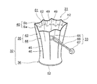
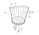
図1は本発明の実施の形態における杖先カバーを杖に装着した状態を示す斜視図、図5は本発明の実施の形態における杖先カバーを杖に装着する前の状態を示す斜視図、図6は本発明の実施の形態における杖先カバーを底面側から見た斜視図、図7は本発明の実施の形態における杖先カバーの部分断面図である。 FIG. 1 is a perspective view showing a state where a cane tip cover is attached to a cane according to an embodiment of the present invention, and FIG. 5 is a perspective view showing a state before the cane tip cover is attached to a cane according to an embodiment of the present invention. 6 is a perspective view of the cane tip cover according to the embodiment of the present invention as seen from the bottom surface side, and FIG. 7 is a partial cross-sectional view of the cane tip cover according to the embodiment of the present invention.
図において、11は杖、31は袋状の形状を有し、杖11に対して着脱自在に装着された杖先カバーである。該杖先カバー31は、杖11に装着されたときに石突き部22(図3)を包囲するカバー本体32、及び該カバー本体32の上端の近傍において、カバー本体32の外周面に巻装されて、カバー本体32を杖11に固定するための固定部材33を備える。前記カバー本体32の上端には、杖11に杖先カバー31を装着する際に、カバー本体32内に石突き部22を挿入するための開口部h2が形成される。
In the figure, 11 is a cane, 31 is a bag-like shape, and a cane tip cover that is detachably attached to the
前記カバー本体32は、筒状の形状を有し、石突き部22の側面を包囲する側面包囲部35、及び該側面包囲部35の下端に取り付けられ、円形の形状を有し、石突き部22の底面S1を包囲する底面包囲部36を備える。なお、前記側面包囲部35は、杖先カバー31が杖11に装着される前の状態において、図5に示されるように、下端から上端にかけて径が徐々に大きくされ、杖先カバー31が杖11に装着されると、図1に示されるように、下端から上端の近傍にかけて径が徐々に小さくされる。
The
前記側面包囲部35は、扇状のシート40の両側縁を縫い合わせることによって形成された筒状体43から成り、該筒状体43の外周面の、円周方向における複数箇所、本実施の形態においては、8箇所に、等ピッチで高さ方向に延在させてステッチ44が形成される。前記シート40は、布、樹脂等の材料、本実施の形態においては、布材料から成る表地Sa及び裏地Sbを重ね、周縁を縫い合わせることによって形成される。また、前記ステッチ44は、前記シート40を、裏地Sb同士が当接する方向に折り、折り目45から微小な、本実施の形態においては、1.5〔mm〕程度の縫い代を残して縫い目46を形成することによって形成される。そして、シート40に複数のステッチ44が形成されることによって、側面包囲部35の円周方向における各ステッチ44間には、径方向内方に向けて突出させられた複数の、本実施の形態においては、8個の湾曲部49が形成される。
The side
このように、前記シート40に複数のステッチ44が形成され、各ステッチ44間に湾曲部49が形成されるので、側面包囲部35に張りを持たせ、カバー本体32の強度を高くすることができる。
In this way, a plurality of
また、杖先カバー31は、杖11に装着される前の状態において、図5に示されるような形状を維持することができ、開口部h2を開いたままにすることができるので、杖11の使用者は、カバー本体32内に石突き部22を容易に挿入することができる。
In addition, the
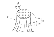
前記底面包囲部36は、前記表地Sa及び裏地Sbを厚紙を挟んで重ね、周縁を縫い合わせることによって板状に形成され、石突き部22の底面S1に対応する形状、すなわち、円形の形状を有する硬質の底板部51、前記カバー本体32の外側底面において、底板部51の下面に接着によって取り付けられた第1の滑止部材としての薄板状の外側底面滑止め52、及び前記カバー本体32の内側底面において、底板部51の上面に接着によって取り付けられた第2の滑止部材としての薄板状の内側底面滑止め53を備える。
The bottom
前記外側底面滑止め52及び内側底面滑止め53は、いずれも、アクリル系樹脂の粘着剤、シリコーンゴム等のゴム材料、ポリ塩化ビニルシート等のシート材等から成り、平坦部54、及び該平坦部54の複数箇所において突出させて形成された突起部55を備える。本実施の形態においては、外側底面滑止め52が平坦部54及び突起部55を備えるようになっているが、外側底面滑止め52を、底板部51の下面の複数箇所にゴム材料を塗布することによって形成された突起により形成することができる。
Each of the outer bottom
また、前記カバー本体32の上端の近傍における内周面には、第3の滑止部材としての内周面滑止め61が帯状に配設される。該内周面滑止め61は、カバー本体32の内側における各湾曲面49の複数箇所、本実施の形態においては、3箇所にアクリル系樹脂の粘着剤を塗布することによって形成された突起62の集合体から成る。本実施の形態において、内周面滑止め61は複数の突起62の集合体から成るが、内周面滑止め61を、各湾曲面49に水平方向に延在させてゴム材料を帯状に塗布することによって形成された帯状体から成るようにすることができる。
Further, on the inner peripheral surface in the vicinity of the upper end of the cover
なお、前記内周面滑止め61は、杖11に杖先カバー31を装着し、カバー本体32内に石突き部22が挿入されたときに、前記各突起62が、ロッド部21における石突き部22より上方の部分と当接させられる。
The inner
すなわち、前記内周面滑止め61は、カバー本体32の上端の近傍で、かつ、側面包囲部35の内周面における所定の位置、本実施の形態においては、側面包囲部35の高さ方向における固定部材33と同じ位置に配設される。
That is, the inner peripheral surface non-slip 61 is in the vicinity of the upper end of the cover
前記固定部材33は、所定のステッチ44に、ステッチ44を形成する際に一体に縫い合わされた被係止具としてのリング状の布製のボタン通し65、弾性材料、本実施の形態においては、ゴム材料から成り、ボタン通し65と連結されたリング状の紐部材66、及び該紐部材66の所定の位置に取り付けられた係止具としてのボタン67を備える。
The fixing
前記紐部材66を引き伸ばし、側面包囲部35の周囲を一周させ、ボタン67をボタン通し65の輪に通すことによって、固定部材33がカバー本体32に巻装される。これにより、カバー本体32の上端の近傍が絞られ、カバー本体32が杖11に装着される。
The fixing
この場合、カバー本体32の上端の近傍が絞られ、突起62が、ロッド部21における石突き部22より上方の部分に移動不能に当接させられるので、杖先カバー31が杖11から抜け落ちることがない。
In this case, the vicinity of the upper end of the cover
このように、本実施の形態においては、杖先カバー31を杖11に対して着脱自在に装着することができるので、杖11の使用者は、屋内に入るときに、杖先カバー31を杖11に装着することによって、屋外で使用した杖11を屋内で使用することができる。したがって、屋外で使用したときに石突き部22に付着した汚れ、ウィルス等が屋内の床面に付着することがない。
Thus, in this embodiment, since the
また、前記カバー本体32の外側底面において、底板部51の下面に外側底面滑止め52が取り付けられているので、杖11を床面に突き当てたときに、杖11が床面を滑ることがない。
Further, since the outer bottom surface non-slip 52 is attached to the lower surface of the
そして、前記カバー本体32の内側底面において、底板部51の上面に内側底面滑止め53が取り付けられているので、杖11の石突き部22が内側底面滑止め53上を滑ることがない。したがって、杖11を床面に突き当てたときに、カバー本体32内で石突き部22が移動するのを防止することができるので、杖先カバー31が安定し、使用者は、杖11を床面に安定させて突き当てることができ、安全に歩行することができる。
And since the inner bottom surface non-slip 53 is attached to the upper surface of the
しかも、前記シート40に複数のステッチ44が形成され、各ステッチ44間に湾曲部49が形成されるので、カバー本体32の強度を高くすることができる。したがって、杖11を床面に突き当てたときにカバー本体32が変形するのを防止することができるので、カバー本体32内で石突き部22が移動するのを一層防止することができる。
In addition, since a plurality of
また、カバー本体32の上端の近傍における内周面に内周面滑止め61が形成され、カバー本体32の上端の近傍における外周面に固定部材33が配設され、固定部材33をカバー本体32に巻装すると、カバー本体32の上端の近傍が絞られ、突起62が、ロッド部21における石突き部22より上方の部分と移動不能に当接させられる。したがって、杖11を床面を突き当てたときにカバー本体32が変形するのを一層防止することができる。
Further, an inner peripheral surface non-slip 61 is formed on the inner peripheral surface in the vicinity of the upper end of the cover
なお、本発明は前記実施の形態に限定されるものではなく、本発明の趣旨に基づいて種々変形させることが可能であり、それらを本発明の範囲から排除するものではない。 In addition, this invention is not limited to the said embodiment, It can change variously based on the meaning of this invention, and does not exclude them from the scope of the present invention.
11 杖
22 石突き部
31 杖先カバー
32 カバー本体
33 固定部材
35 側面包囲部
36 底面包囲部
44 ステッチ
51 底板部
52 外側底面滑止め
53 内側底面滑止め
61 内周面滑止め
S1 底面
11
Claims (3)
(b)該カバー本体の上端の近傍における外周面に巻装されて、カバー本体を杖に固定するための固定部材とを有するとともに、
(c)前記側面包囲部は、外周面における複数箇所に、高さ方向に延在させて形成されたステッチを備え、
(d)前記底面包囲部は、石突き部の底面に対応する形状を有する底板部、該底板部の下面に取り付けられた第1の滑止部材、及び前記底板部の上面に取り付けられた第2の滑止部材を備え、
(e)前記カバー本体の上端の近傍における内周面の、高さ方向における前記固定部材と同じ位置に、杖における石突き部より上方の部分と当接させられる第3の滑止部材が配設されることを特徴とする杖先カバー。 (A) a cover body including a side surface surrounding portion that surrounds the side surface of the stone thrusting portion of the cane, and a bottom surface surrounding portion that is attached to the lower end of the side surface surrounding portion and surrounds the bottom surface of the stone thrusting portion;
(B) having a fixing member wound around the outer peripheral surface in the vicinity of the upper end of the cover body and fixing the cover body to the cane;
(C) The side surface surrounding portion includes stitches formed to extend in the height direction at a plurality of locations on the outer peripheral surface,
(D) The bottom surface surrounding portion includes a bottom plate portion having a shape corresponding to the bottom surface of the stone thrust portion, a first anti-slip member attached to the lower surface of the bottom plate portion, and a first plate attached to the upper surface of the bottom plate portion. 2 non-slip members,
(E) A third non-slip member that is brought into contact with a portion of the cane above the stone thrusting portion is disposed at the same position as the fixing member in the height direction on the inner peripheral surface in the vicinity of the upper end of the cover body. A cane cover characterized by being installed.
Priority Applications (1)
| Application Number | Priority Date | Filing Date | Title |
|---|---|---|---|
| JP2014249579A JP6396196B2 (en) | 2014-12-10 | 2014-12-10 | Cane cover |
Applications Claiming Priority (1)
| Application Number | Priority Date | Filing Date | Title |
|---|---|---|---|
| JP2014249579A JP6396196B2 (en) | 2014-12-10 | 2014-12-10 | Cane cover |
Publications (2)
| Publication Number | Publication Date |
|---|---|
| JP2016106972A true JP2016106972A (en) | 2016-06-20 |
| JP6396196B2 JP6396196B2 (en) | 2018-09-26 |
Family
ID=56122651
Family Applications (1)
| Application Number | Title | Priority Date | Filing Date |
|---|---|---|---|
| JP2014249579A Expired - Fee Related JP6396196B2 (en) | 2014-12-10 | 2014-12-10 | Cane cover |
Country Status (1)
| Country | Link |
|---|---|
| JP (1) | JP6396196B2 (en) |
Citations (4)
| Publication number | Priority date | Publication date | Assignee | Title |
|---|---|---|---|---|
| US5711335A (en) * | 1996-08-28 | 1998-01-27 | Carpin Manufacturing, Inc. | Medical walker foot with collapsible tip |
| JP2000300318A (en) * | 1999-04-22 | 2000-10-31 | ▲はま▼野 征子 | Cover for stick tip |
| US6164306A (en) * | 1999-04-01 | 2000-12-26 | Townsend; George K | Sandpad |
| US20140290708A1 (en) * | 2013-03-29 | 2014-10-02 | Briana N. CROWLEY | Removable slip-resistant cover for a walking device |
-
2014
- 2014-12-10 JP JP2014249579A patent/JP6396196B2/en not_active Expired - Fee Related
Patent Citations (4)
| Publication number | Priority date | Publication date | Assignee | Title |
|---|---|---|---|---|
| US5711335A (en) * | 1996-08-28 | 1998-01-27 | Carpin Manufacturing, Inc. | Medical walker foot with collapsible tip |
| US6164306A (en) * | 1999-04-01 | 2000-12-26 | Townsend; George K | Sandpad |
| JP2000300318A (en) * | 1999-04-22 | 2000-10-31 | ▲はま▼野 征子 | Cover for stick tip |
| US20140290708A1 (en) * | 2013-03-29 | 2014-10-02 | Briana N. CROWLEY | Removable slip-resistant cover for a walking device |
Also Published As
| Publication number | Publication date |
|---|---|
| JP6396196B2 (en) | 2018-09-26 |
Similar Documents
| Publication | Publication Date | Title |
|---|---|---|
| JP2017500121A (en) | Infusion set adhesive system | |
| JP2016504133A5 (en) | ||
| US20070044343A1 (en) | Disposable footwear cover | |
| CN1874697A (en) | gloves or pair of gloves | |
| CN1692876A (en) | blood pressure cuff | |
| CN105292367B (en) | The scuttle hatch of bicycle cleat assembly | |
| JP6396196B2 (en) | Cane cover | |
| US20140223782A1 (en) | Physical Therapy Shoe Covering | |
| US20140090678A1 (en) | Protective glide for medical walker legs | |
| US1504902A (en) | Attachment for crutches | |
| JP2013059514A (en) | Water drop remover of umbrella | |
| US20140290708A1 (en) | Removable slip-resistant cover for a walking device | |
| CN206978894U (en) | Pathologic sampling Protective shoe cover | |
| JP6165220B2 (en) | Engagement tool | |
| US10512307B2 (en) | Adhesive applicator | |
| US11564465B1 (en) | Cane with a leg strap | |
| TWM501864U (en) | Fastening device for needle receiving tank | |
| JP3194646U (en) | Grip cover and cane with grip cover | |
| JP3214984U (en) | Non-slip and walking cane and umbrella with the same | |
| US20160021949A1 (en) | Protective toe sleeve for use during aquatic activity | |
| US20140196202A1 (en) | Protective toe sleeve for use during aquatic activity | |
| CN212520933U (en) | Connecting fixer for connecting gloves and clothes sleeves and clothes with connecting fixer | |
| US20200337940A1 (en) | Baby roller burpee and soothing massaging device | |
| JP3193038U (en) | Vantage with slit | |
| US999136A (en) | Cuff-protector. |
Legal Events
| Date | Code | Title | Description |
|---|---|---|---|
| A621 | Written request for application examination |
Free format text: JAPANESE INTERMEDIATE CODE: A621 Effective date: 20171025 |
|
| A977 | Report on retrieval |
Free format text: JAPANESE INTERMEDIATE CODE: A971007 Effective date: 20180807 |
|
| TRDD | Decision of grant or rejection written | ||
| A01 | Written decision to grant a patent or to grant a registration (utility model) |
Free format text: JAPANESE INTERMEDIATE CODE: A01 Effective date: 20180821 |
|
| A61 | First payment of annual fees (during grant procedure) |
Free format text: JAPANESE INTERMEDIATE CODE: A61 Effective date: 20180829 |
|
| R150 | Certificate of patent or registration of utility model |
Ref document number: 6396196 Country of ref document: JP Free format text: JAPANESE INTERMEDIATE CODE: R150 |
|
| R250 | Receipt of annual fees |
Free format text: JAPANESE INTERMEDIATE CODE: R250 |
|
| LAPS | Cancellation because of no payment of annual fees |