JP2016106904A - Golf club head - Google Patents
Golf club head Download PDFInfo
- Publication number
- JP2016106904A JP2016106904A JP2014248394A JP2014248394A JP2016106904A JP 2016106904 A JP2016106904 A JP 2016106904A JP 2014248394 A JP2014248394 A JP 2014248394A JP 2014248394 A JP2014248394 A JP 2014248394A JP 2016106904 A JP2016106904 A JP 2016106904A
- Authority
- JP
- Japan
- Prior art keywords
- groove
- club head
- golf club
- grooves
- face portion
- Prior art date
- Legal status (The legal status is an assumption and is not a legal conclusion. Google has not performed a legal analysis and makes no representation as to the accuracy of the status listed.)
- Pending
Links
Images
Landscapes
- Golf Clubs (AREA)
Abstract
【課題】スピン性能を向上することが可能なクラブヘッドの提供。【解決手段】フェース部10と、フェース部10に形成された複数のスコアライン20と、フェース部10に形成された複数の溝30と、を備えたゴルフクラブヘッドであって、複数の溝30のそれぞれは、トウ−ヒール方向に延びており、複数の溝30のそれぞれは、その深さがトウ−ヒール方向に周期的に変化している。【選択図】図1To provide a club head capable of improving spin performance. A golf club head including a face portion, a plurality of score lines formed on the face portion, and a plurality of grooves formed on the face portion. Each of the plurality of grooves 30 extends in the toe-heel direction, and the depth of each of the plurality of grooves 30 periodically changes in the toe-heel direction. [Selection] Figure 1
Description
本発明はゴルフクラブヘッドに関するものである。 The present invention relates to a golf club head.
一般に、ゴルフクラブヘッドのフェース部にはスコアラインが形成されている。このスコアラインは、打球のバックスピン量を増大させたり、或いは、雨天時やラフからのショットの場合に、打球のバックスピン量が著しく低減することを抑制する効果がある。しかし、スコアラインだけでは、打球に対するスピン性能の向上に限界がある。そこで、フェース部にスコアラインよりも浅い溝を更に形成したゴルフクラブヘッドが提案されている(例えば特許文献1〜3)。
Generally, a score line is formed on the face portion of a golf club head. This score line has an effect of increasing the backspin amount of the hit ball or suppressing the backspin amount of the hit ball from being remarkably reduced in the case of a rainy day or a shot from the rough. However, the score line alone has a limit in improving the spin performance with respect to the hit ball. Therefore, a golf club head has been proposed in which a groove shallower than the score line is further formed in the face portion (for example,
しかし、従来のゴルフクラブヘッドではスピン性能の向上の点で更なる改善の余地がある。 However, the conventional golf club head has room for further improvement in terms of improving spin performance.
本発明の目的は、スピン性能を向上することにある。 An object of the present invention is to improve spin performance.
本発明によれば、フェース部と、前記フェース部に形成された複数のスコアラインと、前記フェース部に形成された複数の溝と、を備えたゴルフクラブヘッドであって、前記複数の溝の各溝は、トウ−ヒール方向に延びており、前記複数の溝の各溝は、その深さがトウ−ヒール方向に周期的に変化している、ことを特徴とするゴルフクラブヘッドが提供される。 According to the present invention, there is provided a golf club head comprising a face portion, a plurality of score lines formed in the face portion, and a plurality of grooves formed in the face portion. Provided is a golf club head, wherein each groove extends in a toe-heel direction, and each groove of the plurality of grooves has a depth periodically changing in the toe-heel direction. The
本発明によれば、スピン性能を向上することができる。 According to the present invention, the spin performance can be improved.
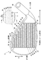
図1は本発明の一実施形態に係るゴルフクラブヘッド1の外観図及び部分拡大図である。同図の例はアイアン型のゴルフクラブヘッドの製造に本発明を適用した例を示す。本発明は、アイアン型のゴルフクラブヘッド、特に、ミドルアイアン、ショートアイアン、ウェッジ型のゴルフクラブヘッドの製造に好適である。具体的には、ロフト角が30度以上70度以下、ヘッド重量が240g以上320g以下のゴルフクラブヘッドの製造に好適である。しかし、本発明はウッド型やユーティリティー型(ハイブリッド型)のゴルフクラブヘッドの製造にも適用可能である。
FIG. 1 is an external view and a partially enlarged view of a
ゴルフクラブヘッド1は、フェース部(打撃面)10及びホゼル部40を備える。ホゼル部40には不図示のシャフトが装着される。
The
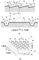
フェース部10には複数のスコアライン20と、複数の溝30とが形成されている。図1〜図3(B)を参照してスコアライン20及び溝30について説明する。図2(A)は図1のI-I線断面図及び部分拡大図であり、図2(B)はのI-I線切断面の部分斜視図である。図3(A)はフェース部10の部分拡大図であり、図3(B)は図3(A)のII-II線断面図である。
A plurality of
複数のスコアライン20はD2方向に配列されている。各々のスコアライン20はトウ−ヒール方向(矢印D1方向)に延設された、互いに平行な直線状の溝である。矢印D2は、フェース部10の上下方向を示し、上側、下側とはゴルフクラブヘッド1のソール部を接地したときの上側、下側を意味する。本実施形態の場合、スコアライン20の延設方向と矢印D2方向とは直交している。なお、図1のI-I線はD2方向と平行である。
The plurality of
本実施形態の場合、各々のスコアライン20の配設間隔(ピッチ)は等間隔(等ピッチ)であるが、配設間隔が異なっていてもよい。本実施形態において、スコアライン20の断面形状は、その長手方向の両端部(トウ側端部、ヒール側端部)を除き、同じである。また、各々のスコアライン20の断面形状は同じである。
In the present embodiment, the arrangement intervals (pitch) of the
スコアライン20は、一対の側壁21と、底壁22とを有し、その断面形状はD2方向の中心線に対して対称な台形状に形成されている。なお、スコアライン20の断面形状は台形状に限られず、V字状等、他の形状でもよい。スコアライン20の縁23には丸みが形成されている。丸みの半径は例えば、0.05mm以上0.3mm以下である。
The
スコアライン20の深さ(底壁22とフェース部10の表面Sとの距離)は0.3mm以上が好ましい。表面Sは、フェース部10にスコアライン20や溝30を埋めた場合の仮想面であり、フェース部10のうちの最も高い位置にある部分(本実施形態では溝30の縁やスコアライン20の縁)を包含する仮想面である。
The depth of the score line 20 (the distance between the
ゴルフクラブヘッド1を競技用とする場合、ルールを充足する点で、深さDsは0.5mm以下とする。スコアライン20の幅(30度測定法による幅)は0.6mm以上が好ましい。ゴルフクラブヘッド1を競技用とする場合、ルールを充足する点で、幅は0.9mm以下とする。
When the
複数の溝30はD2方向に配列されている。各々の溝30はトウ−ヒール方向に延設された溝である。本実施形態の場合、溝30は非直線状の溝であるが、その延設方向はトウ−ヒール方向であり、したがって、その延設方向はスコアライン20と平行である。
The plurality of
溝30は、その幅Wがスコアライン20の幅よりも狭い細溝である。D2方向において隣接するスコアライン20間には、複数の溝30が形成されている。
The
図1の部分拡大図は、フェース部10の正面視での溝30の形状を示している。本実施形態の場合、溝30はD1方向に周期的に変化した形状を有しており、特に、D1方向に周期的に湾曲した波形形状をなしている。換言すると、溝30は、単位形状がD1方向に繰り返し連続的に形成された形状を有しており、本実施形態の場合、単位形状は正弦波形状をなしている。単位形状間のD1方向のピッチP1は、例えば、1mm〜10mmである。なお、各溝30はD1方向に連続した一本の溝を形成しているが、途中で途切れていてもよい。また、溝30は、フェース部10の全域に渡って形成されてもよいし、一部に形成されてもよい。一部に形成する場合、例えば、フェース部10の、D2方向中央部から下部に渡って形成してもよい。
The partial enlarged view of FIG. 1 shows the shape of the
各々の溝30は、互いに平行に形成されている。また、各々の溝30は、D1方向における周期的な湾曲の位相も同位相とされている。換言すると、各々の溝30は、D1方向における山の位置と谷の位置とが同じである。
Each
図2(A)及び図2(B)に示すように、溝30はD2方向上部側に位置する平坦な壁31と、D2方向下部側に位置する平坦な壁32と、から構成されており、溝30の延設方向に直交する断面形状は三角形状である。溝30の最深部33は、幅WのD2方向の中心線よりも上部側に位置しており、溝30の断面形状は幅WのD2方向の中心線に対して非対称な三角形状である。
As shown in FIGS. 2A and 2B, the
幅Wは、溝30の上縁UEと下縁LEとの間の距離である。上縁UEは溝30の縁のうち、フェース部10の上部側の縁であり、下縁LEはフェース部10の下部側の縁である。幅Wは例えば100μm〜800μmである。D2方向に隣接する溝30間のピッチP2は幅Wと同じでもよいし幅Wよりも長くてもよい。ピッチP2は例えば100μm〜800μmである。ここでのピッチP2の数値は、スコアライン20を挟まない場合の数値である。D2方向に隣接するが、スコアライン20を挟む溝30間のピッチは、これとは別に設定することができる。
The width W is a distance between the upper edge UE and the lower edge LE of the
溝30の深さ(最深部33とフェース部10の表面Sとの距離)は例えば10μm〜40μmである。本実施形態の場合、溝30の深さは上縁UEから最深部33に向かって徐々に深くなり、最深部33から下縁LEに向かって徐々に浅くなる。
The depth of the groove 30 (distance between the
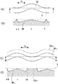
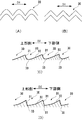
ここで、図3(A)はフェース部10の部分拡大図であり、フェース部10の正面視での溝30の形状を示している。図3(B)は図3(A)のII-II線断面図である。II-II線はD1方向と平行であり、図3(B)は溝30のD1方向の深さの変化を示している。なお、図3(B)は、溝30の深さの変化が分り易いように示しており、実際の縮尺と必ずしも一致するわけではない。
Here, FIG. 3A is a partially enlarged view of the
本実施形態の溝30の構成の場合、各溝30の深さは図3(B)に示すようにトウ−ヒール方向に周期的に変化している。詳しく説明すると、溝30の深さは、II-II線が通る位置が、最深部33に近い位置では相対的に深くなり、最深部33から遠い位置では相対的に浅くなる。
In the case of the configuration of the
同図の例の場合、溝30の深さのトウヒール方向の変化は、深さ無し(a点)→深い(b点)→浅い(c点)→深い(d点)...と変化する。
In the case of the example in the figure, the change of the depth of the
なお、深さの変化を見る切断線の取り方や、溝30間のピッチP2が狭い場合に、深さの変化を見る切断線が複数の溝30を跨る場合があるが、溝30毎に見た場合、その深さの変化はやはり周期的に変化する。
In addition, when the cutting line which sees the change of depth, or the pitch P2 between the
例えば、図3(C)に示すように、切断線をIII-III線とした場合、III-III線は溝30nと、この溝に隣接する溝30n+1に跨り、その断面は図3(D)に示す形状となる。なお、図3(C)及び図3(D)において、溝30nと溝30n+1とを視覚的に区別し易くするため、溝30n+1は破線で図示している。
For example, as shown in FIG. 3 (C), if the cutting line was line III-III, III-III line spans a
このように切断線を設定した場合であっても、溝30nに着目すると、深さのトウヒール方向の変化は、深さ無し(a点)→深い(b点)→浅い(c点)→深い(d点)→深さ無し(e点)...と変化する。
Even when the cutting line is set in this way, if attention is paid to the
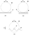
次に、溝30によるスピン性能の向上について説明する。打撃時にゴルフボールはフェース部10の表面に押し潰されるように変形するが、アプローチショットの場合のように打撃力が小さい場合、変形量は小さくなる。このとき、ゴルフボールとフェース部10との接触は点接触に近くなる。従って、接触点を増加することでスピン性能の向上を図ることができる。
Next, the improvement of the spin performance by the
本実施形態の場合、上述したとおり、溝30の深さはトウ−ヒール方向に周期的に変化している。これは打撃時の接触点増加に寄与する。図4(A)は溝30の深さがトウ−ヒール方向に変化しない場合を示し、図4(B)は本実施形態のように溝30の深さがトウ−ヒール方向に周期的に変化する場合を示す。打撃力が小さい場合、図4(A)の例では、ゴルフボールGBとフェース部10との接触が1点での接触に近くなる。一方、図4(B)の例ではゴルフボールGBとフェース部10との接触が多点での接触になり易い。したがって、スピン性能の向上を図ることができる。
In the present embodiment, as described above, the depth of the
また、本実施形態の溝30は、フェース部10の正面視の形状が、D1方向に周期的に湾曲した波形形状をなしている。このため、例えば、ダウンブロー気味にゴルフボールGBを打ち込んだ時に、図4(C)に示すように、ゴルフボールGBが溝30の弧状の上縁部分CPにひっかかって、より高いバックスピン量を得られる。
Further, the
以上の通り、本実施形態のゴルフクラブヘッド1によれば、打撃時の接触点を増加させてスピン性能を向上することができる。
As described above, according to the
本実施形態では、フェース部10の正面視で、溝30の形状がD1方向に周期的に湾曲した波形形状をなしている構成を例示したが、山形形状であってもよい。図5(A)はその一例を示し、単位形状を楕円弧形状として山形形状とした例を示している。図5(B)は他の一例を示し、単位形状を三角形状として山形形状とした例を示している。
In the present embodiment, the configuration in which the shape of the
また、本実施形態では、溝30の延設方向に直交する断面形状を三角形状としたが、他の形状も採用可能である。図5(C)はその一例を示し、壁31及び壁32を互いに連続した湾曲面にしたものであり、輪郭線が弧状である。最深部33はD2方向の中心線よりも上部側に位置している。図5(D)は他の一例を示し、壁31を平坦面とし、壁32を湾曲面としたものである。最深部33はD2方向の中心線よりも上部側に位置している。このように壁31及び32のいずれか一方を湾曲面としてもよい。また、溝30の延設方向に直交する断面形状は台形形状等であってもよい。
In the present embodiment, the cross-sectional shape orthogonal to the extending direction of the
次に、ゴルフクラブヘッド1の製造方法、特に、溝30の形成工程について説明する。溝30は、例えば、切削加工又はレーザ加工で形成することができる。切削加工の場合、特に、ミーリング加工による切削跡として溝30を形成することができる。なお、スコアライン20は、例えば、鍛造、鋳造、切削加工、レーザ加工により形成することができる。また、フェース部10はゴルフクラブヘッド1に一体成形されていてもよいし、フェース部10を構成するフェース部材と、ヘッド本体とを別部材として接合してもよい。
Next, a method for manufacturing the
なお、フェース部10に溝30を形成すると、フェース部10が磨耗し易くなる場合がある。そのため、溝30の形成後、フェース部10の硬度を硬くする表面処理を行うことが好ましい。このような表面処理としては、浸炭処理、窒化処理、軟窒化処理、PVD(Physical Vaper Deposition)処理、イオンプレーティング、DLC(ダイヤモンド ライク カーボン)処理、めっき処理等が挙げられる。特に、浸炭処理や窒化処理といった、表面に別の金属層を形成せず、表面を改質する表面処理が好ましい。
Note that when the
1 ゴルフクラブヘッド、10 フェース部、20 スコアライン、30 溝 1 golf club head, 10 face portion, 20 score lines, 30 grooves
Claims (6)
前記フェース部に形成された複数のスコアラインと、
前記フェース部に形成された複数の溝と、
を備えたゴルフクラブヘッドであって、
前記複数の溝の各溝は、トウ−ヒール方向に延びており、
前記複数の溝の各溝は、その深さがトウ−ヒール方向に周期的に変化している、
ことを特徴とするゴルフクラブヘッド。 A face part;
A plurality of score lines formed on the face portion;
A plurality of grooves formed in the face portion;
A golf club head comprising:
Each groove of the plurality of grooves extends in a toe-heel direction,
The depth of each of the plurality of grooves periodically changes in the toe-heel direction.
A golf club head characterized by that.
前記複数の溝の各溝は、そのトウ−ヒール方向の断面形状が、周期的な波形形状又は山形形状である、
ことを特徴とするゴルフクラブヘッド。 The golf club head according to claim 1,
Each groove of the plurality of grooves has a periodic corrugated shape or a chevron shape in cross-sectional shape in the toe-heel direction.
A golf club head characterized by that.
前記複数の溝の各溝は、
その延設方向と直交する方向で前記フェース部の上部側となる上縁と、前記フェース部の下部側となる下縁とを有し、
前記延設方向と直交する方向で、前記上縁側に最深部を有し、
前記上縁から前記最深部に向かって深くなるように連続的に深さが変化し、かつ、
前記最深部から前記下縁に向かって浅くなるように連続的に深さが変化している、
ことを特徴とするゴルフクラブヘッド。 The golf club head according to claim 1,
Each groove of the plurality of grooves is
An upper edge that is an upper side of the face part in a direction perpendicular to the extending direction, and a lower edge that is a lower side of the face part;
In the direction orthogonal to the extending direction, the upper edge side has a deepest part,
The depth continuously changes so as to become deeper from the upper edge toward the deepest portion, and
The depth continuously changes so as to become shallower from the deepest portion toward the lower edge,
A golf club head characterized by that.
前記複数の溝の各溝は、前記フェース部の正面視で、トウ−ヒール方向に周期的に変化した形状を有する、
ことを特徴とするゴルフクラブヘッド。 The golf club head according to claim 1,
Each groove of the plurality of grooves has a shape that periodically changes in the toe-heel direction in a front view of the face portion.
A golf club head characterized by that.
前記複数の溝の各溝の前記形状は、単位形状間のトウ−ヒール方向のピッチが1mm〜10mmである、
ことを特徴とするゴルフクラブヘッド。 The golf club head according to claim 4,
As for the shape of each groove of the plurality of grooves, a pitch in a toe-heel direction between unit shapes is 1 mm to 10 mm.
A golf club head characterized by that.
前記フェース部に形成された複数のスコアラインと、
前記フェース部に形成された複数の溝と、
を備えたゴルフクラブヘッドであって、
前記複数の溝の各溝は、前記フェース部の正面視で、トウ−ヒール方向に周期的に変化した形状を有し、
前記複数の溝の各溝は、互いに平行であり、
前記複数の溝の各溝は、その延設方向と直交する方向で前記フェース部の上部側に最深部を有する、
ことを特徴とするゴルフクラブヘッド。 A face part;
A plurality of score lines formed on the face portion;
A plurality of grooves formed in the face portion;
A golf club head comprising:
Each groove of the plurality of grooves has a shape that periodically changes in the toe-heel direction in a front view of the face portion,
Each groove of the plurality of grooves is parallel to each other,
Each of the plurality of grooves has a deepest portion on the upper side of the face portion in a direction orthogonal to the extending direction thereof.
A golf club head characterized by that.
Priority Applications (1)
| Application Number | Priority Date | Filing Date | Title |
|---|---|---|---|
| JP2014248394A JP2016106904A (en) | 2014-12-08 | 2014-12-08 | Golf club head |
Applications Claiming Priority (1)
| Application Number | Priority Date | Filing Date | Title |
|---|---|---|---|
| JP2014248394A JP2016106904A (en) | 2014-12-08 | 2014-12-08 | Golf club head |
Publications (1)
| Publication Number | Publication Date |
|---|---|
| JP2016106904A true JP2016106904A (en) | 2016-06-20 |
Family
ID=56122619
Family Applications (1)
| Application Number | Title | Priority Date | Filing Date |
|---|---|---|---|
| JP2014248394A Pending JP2016106904A (en) | 2014-12-08 | 2014-12-08 | Golf club head |
Country Status (1)
| Country | Link |
|---|---|
| JP (1) | JP2016106904A (en) |
Cited By (2)
| Publication number | Priority date | Publication date | Assignee | Title |
|---|---|---|---|---|
| JP2019004995A (en) * | 2017-06-21 | 2019-01-17 | ブリヂストンスポーツ株式会社 | Golf club head |
| JP7556530B2 (en) | 2020-10-20 | 2024-09-26 | 株式会社遠藤製作所 | Golf Clubs |
Citations (3)
| Publication number | Priority date | Publication date | Assignee | Title |
|---|---|---|---|---|
| JP2009261886A (en) * | 2008-04-01 | 2009-11-12 | Bridgestone Sports Co Ltd | Golf club head |
| JP2013230280A (en) * | 2012-04-30 | 2013-11-14 | Dunlop Sports Co Ltd | Golf club head |
| US20130344984A1 (en) * | 2003-12-12 | 2013-12-26 | Acushnet Company | Golf club head having a grooved and textured face |
-
2014
- 2014-12-08 JP JP2014248394A patent/JP2016106904A/en active Pending
Patent Citations (3)
| Publication number | Priority date | Publication date | Assignee | Title |
|---|---|---|---|---|
| US20130344984A1 (en) * | 2003-12-12 | 2013-12-26 | Acushnet Company | Golf club head having a grooved and textured face |
| JP2009261886A (en) * | 2008-04-01 | 2009-11-12 | Bridgestone Sports Co Ltd | Golf club head |
| JP2013230280A (en) * | 2012-04-30 | 2013-11-14 | Dunlop Sports Co Ltd | Golf club head |
Cited By (3)
| Publication number | Priority date | Publication date | Assignee | Title |
|---|---|---|---|---|
| JP2019004995A (en) * | 2017-06-21 | 2019-01-17 | ブリヂストンスポーツ株式会社 | Golf club head |
| JP7029891B2 (en) | 2017-06-21 | 2022-03-04 | ブリヂストンスポーツ株式会社 | Golf club head |
| JP7556530B2 (en) | 2020-10-20 | 2024-09-26 | 株式会社遠藤製作所 | Golf Clubs |
Similar Documents
| Publication | Publication Date | Title |
|---|---|---|
| JP5638844B2 (en) | Golf club head | |
| AU2020220051B2 (en) | Grooves of golf club heads and methods to manufacture grooves of golf club heads | |
| JP6521758B2 (en) | Golf club head having texture pattern and method of manufacturing the same | |
| JP6386276B2 (en) | Golf club head | |
| JP5485779B2 (en) | Golf club head | |
| JP5981208B2 (en) | Forming method and golf club head | |
| JP6386277B2 (en) | Golf club head | |
| JP5296461B2 (en) | Golf club head | |
| JP6376854B2 (en) | Golf club head | |
| JP6362319B2 (en) | Golf club head | |
| JP2011234749A (en) | Golf club head | |
| KR20080048387A (en) | Putter head | |
| JP4954912B2 (en) | Golf club | |
| JP5977065B2 (en) | Golf club head | |
| JP7029891B2 (en) | Golf club head | |
| JP2016106904A (en) | Golf club head | |
| US10894192B2 (en) | Golf club head and manufacturing method thereof | |
| JP5810617B2 (en) | Iron head | |
| JP6600168B2 (en) | Production method | |
| JP6266177B2 (en) | Golf club head groove and method of manufacturing golf club head groove | |
| JP2018183437A (en) | Golf club head | |
| JP5101739B2 (en) | Golf club | |
| JP2018167088A (en) | Golf club head | |
| JP2018167089A (en) | Golf club head |
Legal Events
| Date | Code | Title | Description |
|---|---|---|---|
| A621 | Written request for application examination |
Free format text: JAPANESE INTERMEDIATE CODE: A621 Effective date: 20171121 |
|
| A131 | Notification of reasons for refusal |
Free format text: JAPANESE INTERMEDIATE CODE: A131 Effective date: 20180817 |
|
| A977 | Report on retrieval |
Free format text: JAPANESE INTERMEDIATE CODE: A971007 Effective date: 20180817 |
|
| A601 | Written request for extension of time |
Free format text: JAPANESE INTERMEDIATE CODE: A601 Effective date: 20181015 |
|
| A521 | Request for written amendment filed |
Free format text: JAPANESE INTERMEDIATE CODE: A523 Effective date: 20181130 |
|
| A02 | Decision of refusal |
Free format text: JAPANESE INTERMEDIATE CODE: A02 Effective date: 20181225 |