JP2016100270A - Power storage element - Google Patents
Power storage element Download PDFInfo
- Publication number
- JP2016100270A JP2016100270A JP2014237865A JP2014237865A JP2016100270A JP 2016100270 A JP2016100270 A JP 2016100270A JP 2014237865 A JP2014237865 A JP 2014237865A JP 2014237865 A JP2014237865 A JP 2014237865A JP 2016100270 A JP2016100270 A JP 2016100270A
- Authority
- JP
- Japan
- Prior art keywords
- electrode body
- insulating tape
- separator
- electrode
- wound
- Prior art date
- Legal status (The legal status is an assumption and is not a legal conclusion. Google has not performed a legal analysis and makes no representation as to the accuracy of the status listed.)
- Granted
Links
Images


Classifications
-
- Y—GENERAL TAGGING OF NEW TECHNOLOGICAL DEVELOPMENTS; GENERAL TAGGING OF CROSS-SECTIONAL TECHNOLOGIES SPANNING OVER SEVERAL SECTIONS OF THE IPC; TECHNICAL SUBJECTS COVERED BY FORMER USPC CROSS-REFERENCE ART COLLECTIONS [XRACs] AND DIGESTS
- Y02—TECHNOLOGIES OR APPLICATIONS FOR MITIGATION OR ADAPTATION AGAINST CLIMATE CHANGE
- Y02E—REDUCTION OF GREENHOUSE GAS [GHG] EMISSIONS, RELATED TO ENERGY GENERATION, TRANSMISSION OR DISTRIBUTION
- Y02E60/00—Enabling technologies; Technologies with a potential or indirect contribution to GHG emissions mitigation
- Y02E60/10—Energy storage using batteries
-
- Y—GENERAL TAGGING OF NEW TECHNOLOGICAL DEVELOPMENTS; GENERAL TAGGING OF CROSS-SECTIONAL TECHNOLOGIES SPANNING OVER SEVERAL SECTIONS OF THE IPC; TECHNICAL SUBJECTS COVERED BY FORMER USPC CROSS-REFERENCE ART COLLECTIONS [XRACs] AND DIGESTS
- Y02—TECHNOLOGIES OR APPLICATIONS FOR MITIGATION OR ADAPTATION AGAINST CLIMATE CHANGE
- Y02E—REDUCTION OF GREENHOUSE GAS [GHG] EMISSIONS, RELATED TO ENERGY GENERATION, TRANSMISSION OR DISTRIBUTION
- Y02E60/00—Enabling technologies; Technologies with a potential or indirect contribution to GHG emissions mitigation
- Y02E60/13—Energy storage using capacitors
-
- Y—GENERAL TAGGING OF NEW TECHNOLOGICAL DEVELOPMENTS; GENERAL TAGGING OF CROSS-SECTIONAL TECHNOLOGIES SPANNING OVER SEVERAL SECTIONS OF THE IPC; TECHNICAL SUBJECTS COVERED BY FORMER USPC CROSS-REFERENCE ART COLLECTIONS [XRACs] AND DIGESTS
- Y02—TECHNOLOGIES OR APPLICATIONS FOR MITIGATION OR ADAPTATION AGAINST CLIMATE CHANGE
- Y02P—CLIMATE CHANGE MITIGATION TECHNOLOGIES IN THE PRODUCTION OR PROCESSING OF GOODS
- Y02P70/00—Climate change mitigation technologies in the production process for final industrial or consumer products
- Y02P70/50—Manufacturing or production processes characterised by the final manufactured product
-
- Y—GENERAL TAGGING OF NEW TECHNOLOGICAL DEVELOPMENTS; GENERAL TAGGING OF CROSS-SECTIONAL TECHNOLOGIES SPANNING OVER SEVERAL SECTIONS OF THE IPC; TECHNICAL SUBJECTS COVERED BY FORMER USPC CROSS-REFERENCE ART COLLECTIONS [XRACs] AND DIGESTS
- Y02—TECHNOLOGIES OR APPLICATIONS FOR MITIGATION OR ADAPTATION AGAINST CLIMATE CHANGE
- Y02T—CLIMATE CHANGE MITIGATION TECHNOLOGIES RELATED TO TRANSPORTATION
- Y02T10/00—Road transport of goods or passengers
- Y02T10/60—Other road transportation technologies with climate change mitigation effect
- Y02T10/62—Hybrid vehicles
Abstract
Description
本発明は、正極、負極及びセパレータが巻回されて形成された巻回型電極体を有する蓄電素子に関する。 The present invention relates to a power storage device having a wound electrode body formed by winding a positive electrode, a negative electrode, and a separator.
従来、リチウムイオン電池などの電池を含む蓄電素子において、正極と負極とセパレータとが積層されて、かつ、巻回された巻回型電極体を有するものがある(例えば、特許文献1参照)。このような巻回型電極体を有する蓄電素子では、巻回型電極体の最外周の巻き終わりの位置で、巻回状態が緩まないように最外周を固定する必要がある。電極体の最外周には、一般に、セパレータが配置されるが、このとき、巻回型電極体の最外周の巻き終わりの位置でのセパレータの固定方法としては、接着テープ等の絶縁テープを用いて固定する方法がある。 2. Description of the Related Art Conventionally, some power storage devices including batteries such as lithium ion batteries have a wound electrode body in which a positive electrode, a negative electrode, and a separator are stacked and wound (for example, see Patent Document 1). In the electricity storage device having such a wound electrode body, it is necessary to fix the outermost periphery at the position of the winding end of the outermost periphery of the wound electrode body so that the winding state does not loosen. In general, a separator is disposed on the outermost periphery of the electrode body. At this time, as a method for fixing the separator at the position of the winding end of the outermost periphery of the wound electrode body, an insulating tape such as an adhesive tape is used. There is a way to fix it.
しかしながら、上記従来の絶縁テープを用いて固定する構成では、電極体の巻回状態が緩まないようにしながら、電極体の最外周をより確実に固定することが難しい。このため、当該最外周の部分の固定が緩みやすくなり、巻回型電極体の正極と負極との間に空間(距離)が空きやすくなるため、蓄電素子の性能低下に繋がるおそれがある。 However, in the configuration of fixing using the above-described conventional insulating tape, it is difficult to more reliably fix the outermost periphery of the electrode body while preventing the wound state of the electrode body from being loosened. For this reason, it becomes easy to loosen the fixing of the outermost peripheral part and a space (distance) between the positive electrode and the negative electrode of the wound electrode body is likely to be vacant, which may lead to a decrease in performance of the power storage element.
そこで、本発明は、このような状況に鑑みてなされたものであり、性能が低下することを抑制できる蓄電素子を提供することを目的とする。 Then, this invention is made | formed in view of such a condition, and it aims at providing the electrical storage element which can suppress that performance falls.
上記目的を達成するために、本発明の一態様に係る蓄電素子は、正極、負極、及びセパレータが巻回されて形成された電極体を備える蓄電素子であって、前記電極体が巻回されている方向と同じ方向に、前記電極体の最外周面上に沿って前記電極体に1周以上巻回された状態で、一部が他の部分に重なって接合されている絶縁テープを備える。 In order to achieve the above object, a power storage device according to one embodiment of the present invention is a power storage device including an electrode body formed by winding a positive electrode, a negative electrode, and a separator, and the electrode body is wound. Insulating tape that is partly overlapped and joined to the other part in a state of being wound around the electrode body one or more times along the outermost peripheral surface of the electrode body in the same direction as .
これによれば、絶縁テープは、電極体の最外周面上に沿って電極体を1周以上巻回された状態で、その一部が絶縁テープの他の部分に重なって接合されている。このため、絶縁テープは、電極体の最外周の部分をより確実に固定することができる。 According to this, in the state which wound the electrode body 1 or more times along the outermost peripheral surface of an electrode body, the one part overlaps and the other part of the insulating tape is joined. For this reason, the insulating tape can more reliably fix the outermost peripheral part of the electrode body.
さらに、絶縁テープは、電極体が巻回されている方向と同じ方向に巻回されているため、絶縁テープを、電極体に巻回するときに、電極体の最外周に引張力をかけながら、電極体に1周以上巻回することができる。つまり、巻回型の電極体が緩むことを抑制しながら絶縁テープを電極体に巻回することで、電極体が巻回された状態を維持することができる。このため、蓄電素子の性能低下を抑制できる。 Furthermore, since the insulating tape is wound in the same direction as the direction in which the electrode body is wound, when the insulating tape is wound around the electrode body, a tensile force is applied to the outermost periphery of the electrode body. The electrode body can be wound one or more times. In other words, the state in which the electrode body is wound can be maintained by winding the insulating tape around the electrode body while suppressing the loosening of the wound electrode body. For this reason, the performance fall of an electrical storage element can be suppressed.
また、例えば、前記セパレータは、基材層と、粒子を含む粒子含有層と、を有し、前記粒子含有層は、前記電極体の最外周面に配置されていてもよい。 Further, for example, the separator may include a base material layer and a particle-containing layer containing particles, and the particle-containing layer may be disposed on the outermost peripheral surface of the electrode body.
ここで、上記従来の技術では、次のような課題も生じる。異常時に熱が発生したときであっても、正極と負極との間の絶縁性を維持する目的で、例えばセパレータの片面に無機粒子を含む耐熱層を塗工したセパレータ(以下、「耐熱塗工セパレータ」という。)が考案されている。このような耐熱塗工セパレータを巻回型電極体に適用する場合に、耐熱塗工セパレータの耐熱層には粒子が含まれているために接着テープが接着されにくく、最外周の部分を接着テープ等の絶縁テープで固定することが難しい。このため、当該最外周の部分の固定が緩みやすくなり、巻回型電極体の正極と負極との間に空間(距離)が空きやすくなるため、蓄電素子の性能低下に繋がるおそれがある。 Here, the following problems also occur in the conventional technique. Even when heat is generated at the time of abnormality, for example, a separator in which a heat-resistant layer containing inorganic particles is coated on one side of the separator (hereinafter referred to as “heat-resistant coating” in order to maintain insulation between the positive electrode and the negative electrode. "Separator") has been devised. When such a heat-resistant coated separator is applied to a wound electrode body, since the heat-resistant layer of the heat-resistant coated separator contains particles, it is difficult for the adhesive tape to be bonded, and the outermost part is bonded to the outermost portion. It is difficult to fix with insulating tape. For this reason, it becomes easy to loosen the fixing of the outermost peripheral part and a space (distance) between the positive electrode and the negative electrode of the wound electrode body is likely to be vacant, which may lead to a decrease in performance of the power storage element.
この実施態様によれば、絶縁テープは、電極体の最外周面上に沿って電極体を1周以上巻回された状態で、その一部が接着されやすい絶縁テープの他の部分に重なって接合されている。このため、絶縁テープは、電極体の最外周の部分を固定することができるため、電極体が巻回された状態を維持することができる。これにより、巻回型の電極体が緩むことを抑制することができ、粒子含有層が設けられたセパレータを採用した蓄電素子において、その性能低下を抑制できる。 According to this embodiment, the insulating tape is overlapped with the other part of the insulating tape that is easily bonded to the insulating tape in a state where the electrode body is wound one or more times along the outermost peripheral surface of the electrode body. It is joined. For this reason, since the insulating tape can fix the outermost periphery part of an electrode body, the state by which the electrode body was wound can be maintained. Thereby, it is possible to suppress the winding-type electrode body from being loosened, and it is possible to suppress a decrease in performance of the power storage element employing the separator provided with the particle-containing layer.
また、例えば、前記絶縁テープは、前記電極体の巻回軸方向における前記電極体の両側に配置されていてもよい。 For example, the insulating tape may be disposed on both sides of the electrode body in the winding axis direction of the electrode body.
このように、絶縁テープは、電極体の最外周面の全面を覆わないため、電極体に対する電解液の浸透性を向上させることができる。 Thus, since the insulating tape does not cover the entire outermost peripheral surface of the electrode body, the permeability of the electrolytic solution to the electrode body can be improved.
また、例えば、前記絶縁テープは、前記電極体の巻回軸方向における前記セパレータの端縁からの距離が、前記絶縁テープの幅よりも小さくなる位置に配置されていてもよい。 For example, the insulating tape may be disposed at a position where the distance from the edge of the separator in the winding axis direction of the electrode body is smaller than the width of the insulating tape.
このため、電極体の最外周の端部のうちの、電極体の巻回軸方向の端部がめくれることを抑制できる。これにより、より強固に電極体が巻回された状態を維持することができるため、蓄電素子の性能低下をさらに抑制できる。 For this reason, it can suppress that the edge part of the winding axis direction of an electrode body turns out of the outermost edge parts of an electrode body. Thereby, since the state in which the electrode body is wound more firmly can be maintained, it is possible to further suppress the performance degradation of the power storage element.
また、例えば、前記絶縁テープの内側の端部は、前記電極体の巻回方向における最外周側の端部上に配置されていてもよい。 Further, for example, the inner end portion of the insulating tape may be disposed on the outermost end portion in the winding direction of the electrode body.
このため、絶縁テープを電極体に巻回するときに、セパレータの最外周の端部(電極体の最外周の端部)を押さえながら、絶縁テープを電極体に1周以上巻回することができる。このように、電極体が緩まないように最外周の端部を押さえた上で絶縁テープを巻回することで、電極体が緩まないように電極体が巻回された状態を維持することができるため、蓄電素子の性能低下をさらに抑制できる。 For this reason, when the insulating tape is wound around the electrode body, the insulating tape can be wound around the electrode body one or more times while pressing the outermost edge of the separator (the outermost edge of the electrode body). it can. In this way, by holding the outermost end so that the electrode body does not loosen and then winding the insulating tape, the state in which the electrode body is wound so that the electrode body does not loosen can be maintained. Therefore, it is possible to further suppress the performance degradation of the power storage element.
また、例えば、前記絶縁テープの内側の端部は、前記最外周面のうち、前記電極体の巻回方向における最外周側の端部よりも前記巻回方向側の領域上に配置されていてもよい。 Further, for example, the inner end portion of the insulating tape is disposed on the outermost peripheral surface on a region on the winding direction side with respect to the outermost peripheral end portion in the winding direction of the electrode body. Also good.
これによれば、絶縁テープが電極体を1周以上巻回されて、絶縁テープ自身に重なっている部分を、電極体の最外周側の端部よりも巻回方向側の領域に配置することができる。つまり、絶縁テープ自身が重なって他の部分よりも厚くなっている部分を、電極体の最外周が重なることで生じている段差のうちの高さが低い部位に配置することができるため、電極体及び絶縁テープの組立体の構成をコンパクトにすることができる。 According to this, the insulating tape is wound around the electrode body one or more times, and the portion that overlaps the insulating tape itself is arranged in a region on the winding direction side from the outermost end portion of the electrode body. Can do. In other words, the portion where the insulating tape itself overlaps and is thicker than the other portion can be disposed at a lower height of the step formed by overlapping the outermost periphery of the electrode body. The structure of the assembly of the body and the insulating tape can be made compact.
本発明に係る蓄電素子によれば、蓄電素子の性能が低下することを抑制できる。 According to the electricity storage device of the present invention, it is possible to suppress the performance of the electricity storage device from being deteriorated.
以下、図面を参照しながら、本発明の実施の形態に係る蓄電素子について説明する。なお、以下で説明する実施の形態は、いずれも本発明の好ましい一具体例を示すものである。以下の実施の形態で示される数値、形状、材料、構成要素、構成要素の配置位置及び接続形態等は、一例であり、本発明を限定する主旨ではない。また、以下の実施の形態における構成要素のうち、最上位概念を示す独立請求項に記載されていない構成要素については、任意の構成要素として説明される。また、各図において、寸法等は厳密に図示したものではない。 Hereinafter, a power storage device according to an embodiment of the present invention will be described with reference to the drawings. Each of the embodiments described below shows a preferred specific example of the present invention. The numerical values, shapes, materials, constituent elements, arrangement positions and connecting forms of the constituent elements shown in the following embodiments are merely examples, and are not intended to limit the present invention. In addition, among the constituent elements in the following embodiments, constituent elements that are not described in the independent claims indicating the highest concept are described as optional constituent elements. In each drawing, dimensions and the like are not strictly illustrated.
(実施の形態)
図1は、本発明の実施の形態に係る蓄電素子10の外観を模式的に示す斜視図である。図2は、本発明の実施の形態に係る蓄電素子10の容器100の容器本体111を分離して蓄電素子10が備える各構成要素を示す斜視図である。
(Embodiment)
FIG. 1 is a perspective view schematically showing an external appearance of a
蓄電素子10は、電気を充電し、また、電気を放電することのできる二次電池であり、より具体的には、リチウムイオン二次電池などの非水電解質電池である。例えば、蓄電素子10は、電気自動車(EV)、プラグインハイブリッド電気自動車(PHEV)、またはハイブリッド電気自動車(HEV)などに適用される。なお、蓄電素子10は、非水電解質二次電池には限定されず、非水電解質二次電池以外の二次電池であってもよいし、キャパシタであってもよい。
The
これらの図に示すように、蓄電素子10は、容器100と、正極端子200と、負極端子300と容器100とを備えている。また、容器100の内方には、正極集電体120と、負極集電体130と、電極体140とが収容されている。
As shown in these drawings, the
また、蓄電素子10の容器100の内部には電解液(非水電解質)などの液体が封入されているが、当該液体の図示は省略する。なお、容器100に封入される電解液としては、蓄電素子10の性能を損なうものでなければその種類に特に制限はなく様々なものを選択することができる。
In addition, a liquid such as an electrolytic solution (non-aqueous electrolyte) is sealed inside the
容器100は、矩形筒状で底を備える容器本体111と、容器本体111の開口を閉塞する板状部材である蓋体110とで構成されている。また、容器100は、電極体140等を内部に収容後、蓋体110と容器本体111とが溶接等されることにより、内部を密封することができるものとなっている。なお、蓋体110及び容器本体111の材質は、特に限定されないが、例えばステンレス鋼、アルミニウム、アルミニウム合金など溶接可能な金属であるのが好ましい。
The
電極体140は、正極と負極とセパレータとを備え、電気を蓄えることができる部材である。具体的には、電極体140は、負極と正極との間にセパレータが挟み込まれるように層状に配置されたものを全体が長円形状となるように巻回されて形成されている。なお、同図では、電極体140の形状としては長円形状を示したが、円形状または楕円形状でもよい。電極体140の詳細な構成については、後述する。
The
正極端子200は、電極体140の正極に電気的に接続された電極端子であり、負極端子300は、電極体140の負極に電気的に接続された電極端子である。つまり、正極端子200及び負極端子300は、電極体140に蓄えられている電気を蓄電素子10の外部空間に導出し、また、電極体140に電気を蓄えるために蓄電素子10の内部空間に電気を導入するための金属製の電極端子である。また、正極端子200及び負極端子300は、電極体140の上方に配置された蓋体110に取り付けられている。
The
正極集電体120は、電極体140の正極と容器100の側壁との間に配置され、正極端子200と電極体140の正極とに電気的に接続される導電性と剛性とを備えた部材である。なお、正極集電体120は、電極体140の正極と同様の材料からなり、具体的には、アルミニウムまたはアルミニウム合金などで形成されている。
The positive electrode
負極集電体130は、電極体140の負極と容器100の側壁との間に配置され、負極端子300と電極体140の負極とに電気的に接続される導電性と剛性とを備えた部材である。なお、負極集電体130は、電極体140の負極と同様の材料からなり、具体的には銅または銅合金などで形成されている。
The negative electrode
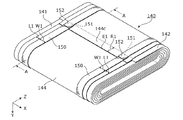
図3は、電極体140の構造を説明するための図である。図4は、電極体140及び絶縁テープ150の外観を示す斜視図である。図5は、電極体140及び絶縁テープ150の断面図である。具体的には、図5の(a)は、図4の電極体140及び絶縁テープ150のA−A断面を示す図であり、図5の(b)は、図5の(a)の領域A1を拡大した拡大図である。
FIG. 3 is a view for explaining the structure of the
電極体140は、図3〜5に示すように、活物質が表面に塗布された正極141及び負極142と、セパレータ143、144とが積層され、かつ、巻回されて形成されている。つまり、電極体140は、正極141と、第一セパレータ143と、負極142と、第二セパレータ144とがこの順に積層された状態で、断面が長円形状になるように巻回されることにより形成される。そして、図4に示すように、巻回されて形成された電極体140の最外周(最後の一周)は、X軸方向(電極体の巻回軸方向)に複数箇所(本実施の形態では2箇所)の位置で絶縁テープ150により固定されている。
As shown in FIGS. 3 to 5, the
正極141は、アルミニウムまたはアルミニウム合金などからなる長尺帯状の正極集電箔の表面に、正極活物質層が形成されたものである。なお、本発明に係る蓄電素子10に用いられる正極141は、特に従来用いられてきたものと異なるところはなく、通常用いられているものが使用できる。
The
負極142は、銅または銅合金などからなる長尺帯状の負極集電箔の表面に、負極活物質層が形成されたものである。なお、本発明に係る蓄電素子10に用いられる負極142は、特に従来用いられてきたものと異なるところはなく、通常用いられているものが使用できる。
The
第一セパレータ143及び第二セパレータ144は、正極141と負極142との間に配置される長尺帯状のセパレータである。第一セパレータ143及び第二セパレータ144は、それぞれが基材層143a、144aと粒子含有層143b、144bとを備えた耐熱塗工セパレータである。
The
基材層143a、144aは、熱可塑性樹脂からなる微多孔性のシートである。
The
粒子含有層143b、144bは、基材層143a、144aの一方の面に配置される、基材層143a、144aとは材質が異なる層である。本実施の形態では、粒子含有層143b、144bは、基材層143a、144aの一方の面上に塗工された層である。ここで、粒子含有層143b、144bは、例えば、アルミナなどの無機粒子とポリフッ化ビニリデン(PVdF)などのバインダの混合物またはポリジビニルベンゼン(PDVB)、ポリアミドなどの耐熱性樹脂とを含む耐熱層(無機塗工層)である。なお、粒子含有層143b、144bは、無機粒子ではなく有機系の粒子を含有していてもよい。また、粒子含有層143b、144bは、基材層143a、144aの両方の面に配置されてもよい。
The particle-containing
つまり、第一セパレータ143及び第二セパレータ144のそれぞれは、基材層143a、144aと、基材層143a、144a上に配置され粒子を含む粒子含有層143b、144bとを有する。そして、第一セパレータ143及び第二セパレータ144は、正極141に粒子含有層143b、144bが対向するように積層され、かつ、負極142に基材層143a、144aが対向するように積層される。
That is, each of the
また、電極体140の最内周には、ポリプロピレン、ポリエチレン等から形成されている巻芯145が配置される。電極体140は、第一セパレータ143及び第二セパレータ144が巻芯145に溶着固定された状態で、正極141、第一セパレータ143、負極142、及び第二セパレータ144が巻回されることにより形成される。
A winding
また、電極体140の最外周面(つまり、最外周の外周面)は、図3及び図4に示すように第二セパレータ144の粒子含有層144bにより構成される。つまり、電極体140は、第二セパレータ144が電極体140の最外周を1周以上巻回され、第二セパレータ144の最外周側の端部144cが第二セパレータ144自身の他の部分に直接重なっている構成である。
Further, the outermost peripheral surface of the electrode body 140 (that is, the outermost peripheral surface) is constituted by the particle-containing
絶縁テープ150は、片側の面が接着性(粘着性)を有する長尺帯状のテープである。絶縁テープ150は、電極体140の最外周面上に沿って、電極体140に1周以上巻回された状態で、絶縁テープ150の一部が絶縁テープ150の他の部分に重なって接着されることにより、接合されている。また、絶縁テープ150は、接着性を有する面が電極体140の最外周面に接触するように配置される。つまり、絶縁テープ150は、自身が電極体140の最外周面に沿って輪状に形成されることにより、電極体140が巻回された状態を維持する。
The insulating
より具体的には、絶縁テープ150の内側の端部151は、電極体140の巻回方向における第二セパレータ144の最外周側の端部144c上に配置されている。そして、絶縁テープ150は、電極体140に1周巻回された状態で、外側の端部152が内側の端部151上に接着されている構成である。
More specifically, the
なお、ここで第二セパレータ144の最外周側の端部144cとは、第二セパレータ144の最外周の端縁E1から所定の範囲R1の領域における部位である。また、所定の範囲R1は、例えば、絶縁テープ150の幅W1の1〜2倍の長さの範囲である。ここで、絶縁テープ150の幅W1が細すぎると、絶縁テープ自身のねじれや、巻ずれなどが発生するおそれがあるため、幅W1は、5〜50mmであることが好ましく、さらに20〜40mmであることがより好ましい。また、絶縁テープの幅を上記の数値範囲とすることにより、電解液が浸透しやすくなり、また、皺が発生した状態で絶縁テープが巻回されることを抑制できる。
Here, the
また、絶縁テープ150は、巻回軸方向における電極体140の両側に配置されている。具体的には、絶縁テープ150は、電極体140の巻回軸方向(つまりX軸方向)における第二セパレータ144の端縁からの距離L1が、絶縁テープ150の幅W1よりも小さくなる位置に配置されている。つまり、2本の絶縁テープ150のうち、X軸方向マイナス側に配置されている絶縁テープ150は、第二セパレータ144のX軸方向マイナス側の端縁からの距離L1が、幅W1よりも小さくなる位置に配置されており、X軸方向プラス側に配置されている絶縁テープ150は、第二セパレータ144のX軸方向プラス側の端縁からの距離L1が、幅W1よりも小さくなる位置に配置されている。
The insulating
また、絶縁テープ150は、電極体140の構成要素である正極141、負極142、及びセパレータ143、144が巻回されている方向と同じ方向に巻回されている。
Further, the insulating
図6は、電極体140及び絶縁テープ150の巻回方向について説明するための図である。具体的には、図6の(a)は、電極体140を形成するときの巻回方向について説明するための図であり、図6の(b)は、電極体140に絶縁テープ150を巻回するときの巻回方向について説明するための図である。
FIG. 6 is a view for explaining the winding direction of the
図6の(a)に示すように、電極体140は、X軸方向プラス側からみた場合に、正極141、負極142、及びセパレータ143、144が左回りに巻回されることにより、形成されている。また、図6の(b)に示すように、絶縁テープ150は、X軸方向プラス側からみた場合に、電極体140に対して左回りに巻回されることにより、形成されている。つまり、図6の(a)及び(b)で示すように、電極体140が形成される巻回方向と、絶縁テープ150の巻回方向とは同じ方向である。
As shown in FIG. 6A, the
なお、巻回方向については、以下のように定義してもよい。 The winding direction may be defined as follows.
巻回された巻回物の内側の位置から外側の位置に当該巻回物を辿った時に、左回りに向かうように巻回されている巻回方向を左方向とし、右回りに向かうように巻回されている巻回方向を右方向としてもよい。 When the wound object is traced from the inner position to the outer position of the wound object, the winding direction wound in the counterclockwise direction is the left direction and the clockwise direction It is good also considering the winding direction currently wound as a right direction.
また、巻回された巻回物の最外周の端縁(端面)が向いている周方向の向きで巻回方向を定義してもよい。つまり、電極体140では、巻回された巻回物の最外周の第二セパレータ144の端縁は、周方向の左方向を向いているため左方向となる。また、絶縁テープ150では、巻回された巻回物の最外周の絶縁テープ150の端縁は、周方向の左方向を向いているため左方向となる。
Moreover, you may define a winding direction by the direction of the circumferential direction in which the outermost edge (end surface) of the wound wound object has faced. That is, in the
以上、本実施の形態によれば、絶縁テープ150は、電極体140の最外周面上に沿って電極体140を1周以上巻回された状態で、その一部である絶縁テープ150の外側の端部152が、接着されやすい絶縁テープ150自身の他の部分である内側の端部151上に接着されている。このため、絶縁テープ150は、電極体140の最外周の部分を固定することができるため、電極体140が巻回された状態を維持することができる。これにより、巻回型の電極体140が緩むことを抑制することができ、耐熱層である粒子含有層143b、144bが設けられたセパレータ143、144を採用した蓄電素子10において、その性能低下を抑制できる。また、蓄電素子10では、耐熱層である粒子含有層143b、144bが設けられたセパレータ143、144を採用しても当該蓄電素子10の性能低下を抑制できるため、異常時に熱が発生したときであっても安全性を確保できる。
As described above, according to the present embodiment, the insulating
また、本実施の形態によれば、絶縁テープ150は、電極体140が巻回されている方向と同じ方向に巻回されている。このため、絶縁テープ150を、電極体140に巻回するときに、電極体140の最外周に引張力をかけながら、電極体140に1周以上巻回することができる。つまり、絶縁テープ150を電極体140に巻回するときに巻回型の電極体140が緩むことを抑制しながら絶縁テープ150を電極体140に巻回することができ、電極体140が巻回された状態を維持することができる。
Further, according to the present embodiment, the insulating
また、本実施の形態によれば、絶縁テープ150の内側の端部151は、巻回方向における第二セパレータ144の最外周側の端部144c上に配置されている。このため、絶縁テープ150を電極体140に巻回するときに、第二セパレータ144の最外周の端部144c(つまり電極体140の最外周の端部)を押さえながら、絶縁テープ150を電極体140に1周以上巻回することができる。このように、電極体140が緩まないように最外周の端部を押さえた上で、絶縁テープ150を巻回することができるため、電極体140が緩まないように電極体140が巻回された状態を維持することができる。
Further, according to the present embodiment, the
また、本実施の形態によれば、絶縁テープ150は、巻回軸方向における電極体140の両側に配置されている。このように、絶縁テープ150は、電極体140の最外周面の全面を覆わないため、電極体140に対する電解液の浸透性を向上させることができる。
Further, according to the present embodiment, the insulating
また、本実施の形態によれば、絶縁テープ150は、電極体140の巻回軸方向(X軸方向)における第二セパレータ144の端縁からの距離L1が、絶縁テープ150の幅W1よりも小さくなる位置に配置されている。このため、電極体140の最外周の端部144cがめくれることを抑制できる。これにより、より強固に電極体140が巻回された状態を維持することができる。
In addition, according to the present embodiment, the insulating
(変形例1)
上記実施の形態における蓄電素子10では、絶縁テープ150の内側の端部151が巻回方向における第二セパレータ144の最外周側の端部144c上に配置されているが、これに限らない。
(Modification 1)
In the
図7は、変形例1に係る電極体140及び絶縁テープ250の外観を示す斜視図である。図8は、変形例1に係る電極体140及び絶縁テープ250の断面図である。具体的には、図8の(a)は、図7の電極体140及び絶縁テープ250のB−B断面を示す図であり、図8の(b)は、図8の(a)の領域A2を拡大した拡大図である。
FIG. 7 is a perspective view showing the appearance of the
図7及び図8に示すように、変形例1に係る電極体140及び絶縁テープ250では、絶縁テープ250は、内側の端部251が電極体140の最外周面のうち、最外周側の端部144cよりも巻回方向側の領域144d上に配置されている。
As shown in FIGS. 7 and 8, in the
ここで、領域144dは、電極体140の最外周面のうちの巻始めの領域である。より具体的には、領域144dは、第二セパレータ144の最外周の端縁E1と巻回方向側に隣接している領域であって、端縁E1から所定の範囲R2の領域である。また、所定の範囲R2は、例えば、絶縁テープ250の幅W1の1〜2倍の長さの範囲である。なお、電極体140の構成は、実施の形態の電極体140の構成と同様であるため、説明を省略する。
Here, the
変形例1に係る電極体140及び絶縁テープ250によれば、絶縁テープ250が電極体140を1周以上巻回されて、絶縁テープ250自身に重なっている部分を、電極体140の最外周側の端部144cよりも巻回方向側の領域144dに配置することができる。つまり、絶縁テープ250の内側の端部251及び外側の端部252が重なることで他の部分よりも厚くなっている部分を、電極体140の最外周が重なることで生じている段差のうちの高さが低い部位に配置することができる。このため、電極体140及び絶縁テープ250の組立体の構成をコンパクトにすることができる。
According to the
また、変形例1に係る電極体140及び絶縁テープ250によれば、絶縁テープ250の内側の端部251を、電極体140の最外周の端部144cが配置される面上と同一の面上において隣接して配置できる。このため、絶縁テープ250に段差が生じないように、電極体140に対して絶縁テープ250を巻回することができる。これにより、少なくとも絶縁テープ250が絶縁テープ250自身に接着している部分を略平面の状態とすることができ、より強固に電極体140が巻回された状態を維持することができる。
Further, according to the
(変形例2)
上記実施の形態及びその変形例では、絶縁テープ150、250は、電極体140に2本設けられているが、2本設けられることに限らずに、1本設けられる構成であってもよいし、3本以上設けられる構成であってもよい。また、絶縁テープ150、250は、電極体140の巻回軸方向(X軸方向)における第二セパレータ144の端縁からの距離L1が、絶縁テープ150、250の幅W1よりも小さくなる位置に配置されていなくてもよい。また、絶縁テープ150、250は、例えば、第二セパレータ144の幅の半分より大きい幅のような幅が広い絶縁テープであってもよい。
(Modification 2)
In the above-described embodiment and its modifications, two insulating
(変形例3)
上記実施の形態及びその変形例では、絶縁テープ150、250は、片面が接着性(粘着性)を有するテープであるが、片面全面が接着性を有していなくてもよく、例えば、電極体140に対して1周以上巻回された絶縁テープの外側の端部のみが接着性を有していればよい。また、例えば、絶縁テープの内側の端部の外周面のみが接着性を有していてもよい。また、両面が接着性を有する絶縁テープが採用されてもよい。
(Modification 3)
In the above embodiment and its modifications, the insulating
(変形例4)
上記実施の形態及びその変形例では、第一セパレータ143及び第二セパレータ144は、それぞれが基材層143a、144aと粒子含有層143b、144bとを備えた耐熱塗工セパレータであるが、粒子含有層143b、144bを備えていないセパレータであってもよい。また、第一セパレータ及び第二セパレータの一方のみが粒子含有層を備えた構成であってもよい。
(Modification 4)
In the said embodiment and its modification, although the
(変形例5)
上記実施の形態及びその変形例では、絶縁テープ150は、その一部が他の部分に重なって接着されることにより、接合されているが、例えば、溶着など別の接合方法で接合されてもよい。
(Modification 5)
In the above-described embodiment and its modification, the insulating
(変形例6)
上記実施の形態及びその変形例では、絶縁テープ150、250は、電極体140に対して1周巻回される構成であるが、電極体140に対して1周以上巻回される構成であってもよい。
(Modification 6)
In the above-described embodiment and its modifications, the insulating
(変形例7)
上記実施の形態及びその変形例では、絶縁テープ絶縁テープ150、250は、その内側の端部151、251上の面にその外側の端部152、252が接着される構成であるが、端部同士で接着される構成に限らずに、電極体140に対して1周以上巻回された状態で巻回されていれば、絶縁テープの端部で接着されなくてもよい。
(Modification 7)
In the above-described embodiment and its modification, the insulating
(変形例8)
上記実施の形態及びその変形例では、絶縁テープ150、250は、周方向の異なる位置においても、X軸方向の位置が一定の渦巻き状に巻回される構成であるが、渦巻き状に限らずに、周方向の位置に応じてX軸方向の位置が異なるようならせん状に巻回される構成であってもよい。
(Modification 8)
In the said embodiment and its modification, although the insulating
以上、本発明の実施の形態及びその変形例に係る蓄電素子について説明したが、本発明は、上記実施の形態及びその変形例に限定されるものではない。つまり、今回開示された実施の形態及びその変形例は全ての点で例示であって制限的なものではないと考えられるべきである。本発明の範囲は上記した説明ではなくて特許請求の範囲によって示され、特許請求の範囲と均等の意味及び範囲内での全ての変更が含まれることが意図される。 Although the power storage device according to the embodiment of the present invention and the modification thereof has been described above, the present invention is not limited to the above-described embodiment and the modification. In other words, it should be considered that the embodiment and its modification disclosed this time are illustrative and not restrictive in all respects. The scope of the present invention is defined by the terms of the claims, rather than the description above, and is intended to include any modifications within the scope and meaning equivalent to the terms of the claims.
また、上記実施の形態及び上記変形例を任意に組み合わせて構築される形態も、本発明の範囲内に含まれる。 Moreover, the form constructed | assembled combining the said embodiment and the said modification arbitrarily is also contained in the scope of the present invention.
本発明の一態様に係る蓄電素子は、粒子を含む層が設けられたセパレータを有する電極体を備えた構成において、性能が低下することを抑制できる蓄電素子などとして有用である。 A power storage element according to one embodiment of the present invention is useful as a power storage element that can suppress a decrease in performance in a configuration including an electrode body including a separator provided with a layer containing particles.
10 蓄電素子
100 容器
110 蓋体
111 容器本体
120 正極集電体
130 負極集電体
140 電極体
141 正極
142 負極
143 第一セパレータ
143a 基材層
143b 粒子含有層
144 第二セパレータ
144a 基材層
144b 粒子含有層
144c 端部
144d 領域
150、250 絶縁テープ
151、251 内側の端部
152、252 外側の端部
200 正極端子
300 負極端子
E1 端縁
R1、R2 所定の範囲
W1 幅
DESCRIPTION OF
Claims (6)
前記電極体が巻回されている方向と同じ方向に、前記電極体の最外周面上に沿って前記電極体に1周以上巻回された状態で、一部が他の部分に重なって接合されている絶縁テープを備える
蓄電素子。 A power storage element comprising an electrode body formed by winding a positive electrode, a negative electrode, and a separator,
In the same direction as the direction in which the electrode body is wound, with one or more turns wound around the electrode body along the outermost peripheral surface of the electrode body, a part of the electrode body is overlapped with another part and joined. A power storage device comprising an insulating tape.
前記粒子含有層は、前記電極体の最外周面に配置されている
請求項1に記載の蓄電素子。 The separator has a base material layer and a particle-containing layer containing particles,
The power storage device according to claim 1, wherein the particle-containing layer is disposed on an outermost peripheral surface of the electrode body.
請求項1又は2に記載の蓄電素子。 The electric storage element according to claim 1, wherein the insulating tape is disposed on both sides of the electrode body in a winding axis direction of the electrode body.
請求項1から3のいずれか1項に記載の蓄電素子。 The said insulating tape is arrange | positioned in the position where the distance from the edge of the said separator in the winding axis direction of the said electrode body becomes smaller than the width | variety of the said insulating tape. The electricity storage device described.
請求項1から4のいずれか1項に記載の蓄電素子。 The electric storage element according to any one of claims 1 to 4, wherein an inner end portion of the insulating tape is disposed on an outermost end portion in a winding direction of the electrode body.
請求項1から4のいずれか1項に記載の蓄電素子。 The end portion on the inner side of the insulating tape is disposed on a region on the winding direction side of the outermost peripheral surface with respect to the outermost peripheral end portion in the winding direction of the electrode body. 5. The electricity storage device according to any one of 4 above.
Priority Applications (1)
| Application Number | Priority Date | Filing Date | Title |
|---|---|---|---|
| JP2014237865A JP6682758B2 (en) | 2014-11-25 | 2014-11-25 | Storage element |
Applications Claiming Priority (1)
| Application Number | Priority Date | Filing Date | Title |
|---|---|---|---|
| JP2014237865A JP6682758B2 (en) | 2014-11-25 | 2014-11-25 | Storage element |
Publications (2)
| Publication Number | Publication Date |
|---|---|
| JP2016100270A true JP2016100270A (en) | 2016-05-30 |
| JP6682758B2 JP6682758B2 (en) | 2020-04-15 |
Family
ID=56078006
Family Applications (1)
| Application Number | Title | Priority Date | Filing Date |
|---|---|---|---|
| JP2014237865A Active JP6682758B2 (en) | 2014-11-25 | 2014-11-25 | Storage element |
Country Status (1)
| Country | Link |
|---|---|
| JP (1) | JP6682758B2 (en) |
Cited By (6)
| Publication number | Priority date | Publication date | Assignee | Title |
|---|---|---|---|---|
| CN109428109A (en) * | 2017-09-05 | 2019-03-05 | 住友化学株式会社 | The manufacturing method of electrode for secondary battery component and electrode for secondary battery component |
| WO2021176961A1 (en) * | 2020-03-06 | 2021-09-10 | 三洋電機株式会社 | Secondary battery |
| WO2021243611A1 (en) * | 2020-06-03 | 2021-12-09 | 宁德新能源科技有限公司 | Insulating tape, electrode plate and electrochemical device |
| CN114464900A (en) * | 2020-11-09 | 2022-05-10 | 泰星能源解决方案有限公司 | Battery with a battery cell |
| JP2022137789A (en) * | 2021-03-09 | 2022-09-22 | プライムプラネットエナジー&ソリューションズ株式会社 | secondary battery |
| WO2023020127A1 (en) * | 2021-08-19 | 2023-02-23 | 宁德时代新能源科技股份有限公司 | Electrode assembly, battery cell, battery, and electric device |
Citations (7)
| Publication number | Priority date | Publication date | Assignee | Title |
|---|---|---|---|---|
| JP2003178792A (en) * | 2001-11-06 | 2003-06-27 | Samsung Sdi Co Ltd | Secondary battery |
| JP2005216754A (en) * | 2004-01-30 | 2005-08-11 | Sanyo Electric Co Ltd | Battery |
| JP2008010242A (en) * | 2006-06-28 | 2008-01-17 | Sanyo Electric Co Ltd | Cylindrical storage battery |
| JP2008186708A (en) * | 2007-01-30 | 2008-08-14 | Sony Corp | Secondary battery |
| JP2009199974A (en) * | 2008-02-25 | 2009-09-03 | Panasonic Corp | Electrode group for nonaqueous secondary battery, and secondary battery using the same |
| JP2012230865A (en) * | 2011-04-27 | 2012-11-22 | Gs Yuasa Corp | Power generation element and power generation element termination processing method |
| US20140141338A1 (en) * | 2012-11-19 | 2014-05-22 | Samsung Sdi Co., Ltd. | Rechargeable lithium battery |
-
2014
- 2014-11-25 JP JP2014237865A patent/JP6682758B2/en active Active
Patent Citations (7)
| Publication number | Priority date | Publication date | Assignee | Title |
|---|---|---|---|---|
| JP2003178792A (en) * | 2001-11-06 | 2003-06-27 | Samsung Sdi Co Ltd | Secondary battery |
| JP2005216754A (en) * | 2004-01-30 | 2005-08-11 | Sanyo Electric Co Ltd | Battery |
| JP2008010242A (en) * | 2006-06-28 | 2008-01-17 | Sanyo Electric Co Ltd | Cylindrical storage battery |
| JP2008186708A (en) * | 2007-01-30 | 2008-08-14 | Sony Corp | Secondary battery |
| JP2009199974A (en) * | 2008-02-25 | 2009-09-03 | Panasonic Corp | Electrode group for nonaqueous secondary battery, and secondary battery using the same |
| JP2012230865A (en) * | 2011-04-27 | 2012-11-22 | Gs Yuasa Corp | Power generation element and power generation element termination processing method |
| US20140141338A1 (en) * | 2012-11-19 | 2014-05-22 | Samsung Sdi Co., Ltd. | Rechargeable lithium battery |
Cited By (11)
| Publication number | Priority date | Publication date | Assignee | Title |
|---|---|---|---|---|
| CN109428109A (en) * | 2017-09-05 | 2019-03-05 | 住友化学株式会社 | The manufacturing method of electrode for secondary battery component and electrode for secondary battery component |
| US20190074551A1 (en) * | 2017-09-05 | 2019-03-07 | Sumitomo Chemical Company, Limited | Electrode assembly for secondary battery and method for producing electrode assembly for secondary battery |
| JP2019046798A (en) * | 2017-09-05 | 2019-03-22 | 住友化学株式会社 | Electrode assembly for secondary battery and manufacturing method thereof |
| WO2021176961A1 (en) * | 2020-03-06 | 2021-09-10 | 三洋電機株式会社 | Secondary battery |
| WO2021243611A1 (en) * | 2020-06-03 | 2021-12-09 | 宁德新能源科技有限公司 | Insulating tape, electrode plate and electrochemical device |
| CN114464900A (en) * | 2020-11-09 | 2022-05-10 | 泰星能源解决方案有限公司 | Battery with a battery cell |
| EP3996197A1 (en) * | 2020-11-09 | 2022-05-11 | Prime Planet Energy & Solutions, Inc. | Battery |
| US20220149440A1 (en) * | 2020-11-09 | 2022-05-12 | Prime Planet Energy & Solutions, Inc. | Battery |
| JP2022137789A (en) * | 2021-03-09 | 2022-09-22 | プライムプラネットエナジー&ソリューションズ株式会社 | secondary battery |
| JP7385613B2 (en) | 2021-03-09 | 2023-11-22 | プライムプラネットエナジー&ソリューションズ株式会社 | secondary battery |
| WO2023020127A1 (en) * | 2021-08-19 | 2023-02-23 | 宁德时代新能源科技股份有限公司 | Electrode assembly, battery cell, battery, and electric device |
Also Published As
| Publication number | Publication date |
|---|---|
| JP6682758B2 (en) | 2020-04-15 |
Similar Documents
| Publication | Publication Date | Title |
|---|---|---|
| JP6735445B2 (en) | Wound battery | |
| JP5271245B2 (en) | Secondary battery | |
| JP6682758B2 (en) | Storage element | |
| JP6582500B2 (en) | Electricity storage element | |
| EP2610945B1 (en) | Stacked cell | |
| JP6432952B1 (en) | Electrochemical cell | |
| JP6270613B2 (en) | Prismatic secondary battery | |
| JP2020080282A (en) | Electrochemical cell | |
| JP6206039B2 (en) | Method for manufacturing power storage element | |
| JP6045987B2 (en) | Prismatic secondary battery | |
| JP2016105360A (en) | Power storage device | |
| JP2017069059A (en) | Power storage element and method for manufacturing power storage element | |
| JP6299243B2 (en) | Storage element and safety valve | |
| JP6750242B2 (en) | Storage element | |
| JP6089832B2 (en) | Electricity storage element | |
| JP2018055904A (en) | Electrochemical cell and manufacturing method of the electrochemical cell | |
| JP6155724B2 (en) | Power storage device and method for manufacturing power storage device | |
| JP2016039041A (en) | Power storage element and manufacturing method for the same | |
| JP6738565B2 (en) | Electric storage element and method for manufacturing electric storage element | |
| JP2016039090A (en) | Power storage element, and power storage device | |
| JP2016066535A (en) | Power storage element and manufacturing method of power storage element | |
| JP7304788B2 (en) | electrochemical cell | |
| JP2018200822A (en) | Laminate type battery | |
| WO2017208509A1 (en) | Power storage device and method for producing same | |
| JP7322872B2 (en) | Storage element |
Legal Events
| Date | Code | Title | Description |
|---|---|---|---|
| A711 | Notification of change in applicant |
Free format text: JAPANESE INTERMEDIATE CODE: A711 Effective date: 20150416 |
|
| A621 | Written request for application examination |
Free format text: JAPANESE INTERMEDIATE CODE: A621 Effective date: 20171004 |
|
| A977 | Report on retrieval |
Free format text: JAPANESE INTERMEDIATE CODE: A971007 Effective date: 20180725 |
|
| A131 | Notification of reasons for refusal |
Free format text: JAPANESE INTERMEDIATE CODE: A131 Effective date: 20180807 |
|
| A601 | Written request for extension of time |
Free format text: JAPANESE INTERMEDIATE CODE: A601 Effective date: 20181003 |
|
| A521 | Request for written amendment filed |
Free format text: JAPANESE INTERMEDIATE CODE: A523 Effective date: 20181203 |
|
| A131 | Notification of reasons for refusal |
Free format text: JAPANESE INTERMEDIATE CODE: A131 Effective date: 20190528 |
|
| A601 | Written request for extension of time |
Free format text: JAPANESE INTERMEDIATE CODE: A601 Effective date: 20190722 |
|
| A521 | Request for written amendment filed |
Free format text: JAPANESE INTERMEDIATE CODE: A523 Effective date: 20190924 |
|
| TRDD | Decision of grant or rejection written | ||
| A01 | Written decision to grant a patent or to grant a registration (utility model) |
Free format text: JAPANESE INTERMEDIATE CODE: A01 Effective date: 20200225 |
|
| A61 | First payment of annual fees (during grant procedure) |
Free format text: JAPANESE INTERMEDIATE CODE: A61 Effective date: 20200309 |
|
| R150 | Certificate of patent or registration of utility model |
Ref document number: 6682758 Country of ref document: JP Free format text: JAPANESE INTERMEDIATE CODE: R150 |