JP2016100113A - connector - Google Patents
connector Download PDFInfo
- Publication number
- JP2016100113A JP2016100113A JP2014234482A JP2014234482A JP2016100113A JP 2016100113 A JP2016100113 A JP 2016100113A JP 2014234482 A JP2014234482 A JP 2014234482A JP 2014234482 A JP2014234482 A JP 2014234482A JP 2016100113 A JP2016100113 A JP 2016100113A
- Authority
- JP
- Japan
- Prior art keywords
- housing
- lock arm
- detection member
- lock
- posture
- Prior art date
- Legal status (The legal status is an assumption and is not a legal conclusion. Google has not performed a legal analysis and makes no representation as to the accuracy of the status listed.)
- Pending
Links
Images


Classifications
-
- H—ELECTRICITY
- H01—ELECTRIC ELEMENTS
- H01R—ELECTRICALLY-CONDUCTIVE CONNECTIONS; STRUCTURAL ASSOCIATIONS OF A PLURALITY OF MUTUALLY-INSULATED ELECTRICAL CONNECTING ELEMENTS; COUPLING DEVICES; CURRENT COLLECTORS
- H01R13/00—Details of coupling devices of the kinds covered by groups H01R12/70 or H01R24/00 - H01R33/00
- H01R13/64—Means for preventing incorrect coupling
- H01R13/641—Means for preventing incorrect coupling by indicating incorrect coupling; by indicating correct or full engagement
-
- H—ELECTRICITY
- H01—ELECTRIC ELEMENTS
- H01R—ELECTRICALLY-CONDUCTIVE CONNECTIONS; STRUCTURAL ASSOCIATIONS OF A PLURALITY OF MUTUALLY-INSULATED ELECTRICAL CONNECTING ELEMENTS; COUPLING DEVICES; CURRENT COLLECTORS
- H01R13/00—Details of coupling devices of the kinds covered by groups H01R12/70 or H01R24/00 - H01R33/00
- H01R13/62—Means for facilitating engagement or disengagement of coupling parts or for holding them in engagement
- H01R13/627—Snap or like fastening
- H01R13/6271—Latching means integral with the housing
- H01R13/6272—Latching means integral with the housing comprising a single latching arm
-
- H—ELECTRICITY
- H01—ELECTRIC ELEMENTS
- H01R—ELECTRICALLY-CONDUCTIVE CONNECTIONS; STRUCTURAL ASSOCIATIONS OF A PLURALITY OF MUTUALLY-INSULATED ELECTRICAL CONNECTING ELEMENTS; COUPLING DEVICES; CURRENT COLLECTORS
- H01R43/00—Apparatus or processes specially adapted for manufacturing, assembling, maintaining, or repairing of line connectors or current collectors or for joining electric conductors
- H01R43/26—Apparatus or processes specially adapted for manufacturing, assembling, maintaining, or repairing of line connectors or current collectors or for joining electric conductors for engaging or disengaging the two parts of a coupling device
Abstract
Description
本発明は、コネクタに関するものである。 The present invention relates to a connector.
特許文献1には、片持ち状に延出した形態のロックアームが形成されたハウジング本体と、ハウジング本体に取り付けられた検知部材とを備えたコネクタが開示されている。ハウジング本体を相手側ハウジングに嵌合する前の状態では、検知部材は、ロックアームに当接することにより初期位置に留め置かれる。ハウジング本体を相手側ハウジングに嵌合すると、検知部材とロックアームとの当接が解除されるので、検知部材を初期位置から嵌合位置へ押し込むことができる。これにより、検知部材が嵌合位置へ押し込めるか否かに基づいて、ハウジング本体と相手側ハウジングとの嵌合状態を検知することができる。 Patent Document 1 discloses a connector including a housing body in which a lock arm having a cantilever shape is formed and a detection member attached to the housing body. In a state before the housing main body is fitted to the counterpart housing, the detection member is held in the initial position by contacting the lock arm. When the housing body is fitted into the mating housing, the contact between the detection member and the lock arm is released, so that the detection member can be pushed from the initial position to the fitting position. Thereby, the fitting state of the housing body and the counterpart housing can be detected based on whether or not the detection member is pushed into the fitting position.
ロックアームの延出端部は、ロックアームをロック解除方向へ撓ませるための操作力を付与するための解除操作部となっている。そして、ハウジング本体には、この解除操作部が不用意に押し操作されたり、異物が解除操作部に干渉したりするのを防止する手段として、ハウジング本体には解除操作部を覆うようなアーチ状の保護壁が形成されている。 The extended end portion of the lock arm serves as a release operation portion for applying an operation force for bending the lock arm in the lock release direction. The housing body has an arch shape that covers the release operation portion as a means for preventing the release operation portion from being inadvertently pushed and foreign matter interfering with the release operation portion. A protective wall is formed.
しかし、保護壁が解除操作部を覆っていると、意図的にロック解除するために解除操作部を押し操作しようとするときに、作業者の指が保持壁と干渉するため、作業性が良くないという問題が生じる。 However, if the protective wall covers the release operation part, the operator's finger interferes with the holding wall when trying to push the release operation part to intentionally release the lock. The problem of not.
本発明は上記のような事情に基づいて完成されたものであって、ロックアームをロック解除操作する際の作業性に支障を来すことなく、ロックアームを保護できるようにすることを目的とする。 The present invention has been completed based on the above-described circumstances, and an object thereof is to protect a lock arm without hindering workability when the lock arm is unlocked. To do.
本発明のコネクタは、
第1ハウジングと、
前記第1ハウジングと嵌合可能な第2ハウジングと、
前記第1ハウジングに弾性撓み可能に形成され、前記第2ハウジングと係止することで前記第1ハウジングと前記第2ハウジングを嵌合状態にロックするロックアームと、
前記第1ハウジングに取り付けられ、前記第1ハウジングと前記第2ハウジングが半嵌合の状態では前記ロックアームへの当接によって初期位置に保持され、前記第1ハウジングと前記第2ハウジングが正規嵌合されると前記ロックアームから解離して検知位置への移動が許容される検知部材と、
前記検知部材に設けられ、常には前記ロックアームを覆う保護姿勢に保持され、前記ロックアームにロック解除方向の押圧力を付与する押圧姿勢への弾性撓みが可能な可動保護部と、
前記検知部材が初期位置にあるときには、前記可動保護部が前記押圧姿勢へ弾性撓みすることを許容し、且つ前記検知部材が検知位置にあるときには、前記可動保護部を前記保護姿勢に保持する姿勢保持部とを備えているところに特徴を有する。
The connector of the present invention
A first housing;
A second housing engageable with the first housing;
A lock arm that is formed in the first housing so as to be elastically deformable, and locks the first housing and the second housing in a fitted state by engaging with the second housing;
The first housing is attached to the first housing, and when the first housing and the second housing are half-fitted, the first housing and the second housing are properly fitted by being held at an initial position by contact with the lock arm. A detection member that is disengaged from the lock arm and allowed to move to the detection position when combined,
A movable protective portion that is provided on the detection member, is always held in a protective posture covering the lock arm, and can be elastically bent to a pressing posture that applies a pressing force in the unlocking direction to the lock arm;
When the detection member is in the initial position, the movable protection unit is allowed to elastically bend to the pressing posture, and when the detection member is in the detection position, the movable protection unit is held in the protection posture. It is characterized by having a holding part.
検知部材が検知位置にある状態では、可動保護部が保護姿勢に保持されるので、ロックアームは可動保護部によって確実に保護される。ロックアームをロック解除方向へ撓ませる際には、検知部材を初期位置へ移動させ、可動保護部を押圧姿勢へ変位させればよい。このように、本発明によれば、ロックアームをロック解除操作する際の作業性に支障を来すことなく、ロックアームを保護することができる。 In a state where the detection member is in the detection position, the movable protection portion is held in the protective posture, so that the lock arm is reliably protected by the movable protection portion. When the lock arm is bent in the unlocking direction, the detection member may be moved to the initial position and the movable protection portion may be displaced to the pressing posture. As described above, according to the present invention, the lock arm can be protected without hindering the workability when the lock arm is unlocked.
(1)本発明のコネクタは、
前記姿勢保持部が、前記第2ハウジングに形成されていてもよい。
この構成によれば、姿勢保持部を第1ハウジングに形成する場合に比べると、第1ハウジングの形状を簡素化することができる。
(1) The connector of the present invention
The posture holding portion may be formed on the second housing.
According to this configuration, the shape of the first housing can be simplified as compared with the case where the posture holding portion is formed in the first housing.
(2)本発明のコネクタは、(1)において、
前記第2ハウジングは、内面に前記ロックアームと係止可能なロック部が形成されたフード部を有しており、
前記フード部の外面が前記姿勢保持部となっていてもよい。
この構成によれば、ロック部の形成母体であるフード部が、姿勢保持部としての機能も兼ね備えているので、フード部とは別に姿勢保持部を形成する場合に比べると、第2ハウジングの形状を簡素化することができる。
(2) In the connector of the present invention,
The second housing has a hood portion formed with a lock portion engageable with the lock arm on the inner surface,
The outer surface of the hood portion may be the posture holding portion.
According to this structure, since the hood part which is a formation base of the lock part also has a function as a posture holding part, the shape of the second housing is compared with the case where the posture holding part is formed separately from the hood part. Can be simplified.
<実施例1>
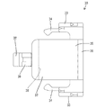
以下、本発明を具体化した実施例1を図1〜図11を参照して説明する。本実施例のコネクタは、合計樹脂製の第1ハウジング10と、合成樹脂製の検知部材30と、合成樹脂製の第2ハウジング40とを備えて構成されている。
<Example 1>
A first embodiment embodying the present invention will be described below with reference to FIGS. The connector of the present embodiment includes a
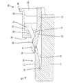
第1ハウジング10は、ブロック状をなす端子収容部11と、ロックアーム12と、左右一対のガイド壁部20と一体に形成して構成されている。端子収容部11内には、周知形態の複数の雌端子金具(図示省略)が収容されている。ロックアーム12は、端子収容部11の上面に沿うように配されている。ロックアーム12の前端部(図2における左側の端部)は、脚部13を介して端子収容部11の上面に支持されている。つまり、ロックアーム12は、後方へ片持ち状に延出した形態である。端子収容部11の上面とロックアーム12の下面との間には、ロックアーム12がロック解除方向へ弾性撓みすることを許容するための撓み空間14が形成されている。ロックアーム12は、常にはロック姿勢(図2,9,10を参照)を保つが、脚部13を略支点として撓み空間14内に進出するロック解除姿勢(図8,11を参照)へ弾性撓みし得るようになっている。
The
ロックアーム12は、脚部13の左右両端部から後方へ延出する左右対称な一対のアーム部15を有している。両アーム部15の後端部は、受圧部16によって橋渡し状に連結されている。ロックアーム12は、左右両アーム部15のうち略前半領域を連結する板状連結部17を有している。板状連結部17の後端部(延出端部)には、その上面(撓み空間14とは反対側の面)から突出するロック突起18が形成されている。同じく板状連結部17の後端部には、板状連結部17の下面(端子収容部11との対向面であり、撓み空間14に臨む面)と板状連結部17の後端面とに開放された係止凹部19が形成されている。係止凹部19は、前後方向及び左右方向において、ロック突起18と対応するように位置している。
The
一対のガイド壁部20は、端子収容部11の上面後端部における左右両側縁から上方へ延出した形態である。一対のガイド壁部20は、ロックアーム12の受圧部16を、左右両側から非接触の状態で挟むように位置している。また、端子収容部11の上面のうち一対のガイド壁部20の内面に近い位置には、一対のストッパ(図示省略)が形成されている。
The pair of
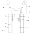
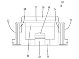
図5〜7に示すように、検知部材30は、底壁部31と、係止アーム32と、左右対称な一対の側壁部33と、左右対称な一対の板状係止部34と、板状支持部35と、可動保護部37とを一体に形成したものである。係止アーム32は、底壁部31の前端縁における中央位置から前方(図2,6,7における左方)へ片持ち状に延出した形態である。係止アーム32は、その後端部(側壁部33の前端縁)を略支点として、下方へ弾性撓みし得るようになっている。係止アーム32の上面には、その前端部よりも少し後方の位置が突出する当接部39が形成されている。一対の側壁部33は、底壁部31の左右両側縁における後端部から上方へ延出した形態である。一対の板状係止部34は、側壁部33の前端縁から前方へ片持ち状に延出した形態である。
As shown in FIGS. 5 to 7, the
検知部材30は、底壁部31を端子収容部11の上面に当接させるとともに、左右両側壁部33と板状係止部34を、ガイド壁部20の内面に当接又は接近して対向させた状態で、第1ハウジング10の外面に取り付けられている。両ハウジング10,40が未嵌合の状態では、板状係止部34が第1ハウジング10のストッパに係止される。この係止作用により、検知部材30は、第1ハウジング10に対して後方への移動を規制された状態で初期位置(図1,2,8,9,11を参照)に保持される。また、検知部材30は、底壁部31を端子収容部11の上面に摺接させながら、初期位置よりも前方の検知位置(図10を参照)へ平行移動し得るようになっている。
The
両ハウジング10,40が未嵌合で検知部材30が初期位置にある状態では、図2に示すように、係止アーム32が受圧部16の下方を潜り、係止アーム32の前端部が、ロックアーム12の係止凹部19内に嵌合する。そして、係止アーム32の当接部39が、ロックアーム12の板状連結部17の後端面に対し、後方から当接又は接近して対向する状態となる。当接部39がロックアーム12に当接すると、検知部材30は、検知位置(前方)への移動を規制される。係止アーム32の前端部がロックアーム12から解離すると、検知部材30は検知位置への移動を許容される。検知部材30が検知位置へ移動すると、図10に示すように、係止アーム32が下方へ弾性撓みして、当接部39が係止凹部19内に潜り込む。
In a state where both the
板状支持部35は、左右両側壁部33の上端縁(延出端縁)同士を連結した形態である。板状支持部35の上面には、その後端縁から上方へリブ状に突出した形態の指掛け部36が形成されている。可動保護部37は、板状支持部35の前端縁から前方へ片持ち状に延出した形態であり、平板状をなしている。可動保護部37は、常には、保護姿勢(図2,8〜10を参照)に保持されている。保護姿勢の可動保護部37は、検知部材30の初期位置と検知位置との間の移動方向と略平行をなしている。可動保護部37は、その後端縁(板状支持部35の前端縁)を略支点として下方の押圧姿勢(図11を参照)へ弾性撓みし得るようになっている。また、可動保護部37には、その前端縁から下方へリブ状に突出した形態の押圧部38が形成されている。
The plate-
検知部材30が初期位置にある状態では、図2に示すように、押圧部38が、前後方向(検知部材30の移動方向)において、ロックアーム12の受圧部16と対応するように位置する。即ち、押圧部38の下面が、受圧部16の上面に対し、接近して対向する位置関係、又は下方への押圧力を付与する。また、検知部材30が検知位置に移動すると、図10に示すように、押圧部38が、受圧部16よりも前方に位置する。
In the state where the
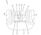
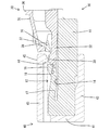
第2ハウジング40は、図8〜11に示すように、端子収容部11の前端面と対向する形態の端子保持部41と、端子保持部41の外周縁から前方(図8〜11における右方)へ片持ち状に延出した形態の角筒状をなすフード部42とを一体に形成した形態である。端子保持部41には、複数の雄端子金具(図示省略)が保持され、複数の雄端子金具の前端部がフード部42により一括した包囲されている。フード部42を構成する上壁部43には、その前端縁から下方(内側)へリブ状に突出した形態のロック部44が形成されている。また、上壁部43の外面は、姿勢保持部45となっている。
As shown in FIGS. 8 to 11, the
次に、本実施例の作用を説明する。第1ハウジング10と第2ハウジング40を嵌合する際には、フード部42内に端子収容部11とロックアーム12を進入させる。嵌合の過程では、図8に示すように、ロック突起18がロック部44と干渉することにより、ロックアーム12がロック姿勢からロック解除姿勢へ弾性撓みさせられる。これに伴い、前端部を係止凹部19内に進入させている係止アーム32も、下方弾性撓みさせられるが、ロックアーム12に対する当接部39の当接状態は維持されるので、検知部材30は、初期位置に留め置かれたままである。また、ロックアーム12が下方へ弾性撓みするのに伴い、受圧部16が下動保持部の押圧部38から下方へ遠ざかる。
Next, the operation of this embodiment will be described. When fitting the
この状態から嵌合が進むと、ロック突起18がロック部44を通過し、図9に示すように、両ハウジング10,40が正規の嵌合状態となり、雌端子金具と雄端子金具が接続される。そして、ロック突起18がロック部44を通過すると、ロックアーム12がロック姿勢へ弾性復帰する。ロックアーム12の弾性復帰に伴い、ロック突起18とロック部44が係止し、この係止作用により、正規嵌合状態の両ハウジング10,40が離脱規制された状態にロックされる。
When the fitting proceeds from this state, the
また、ロックアーム12がロック姿勢へ弾性復帰すると、係止凹部19が係止アーム32の前端部から上方へ離間する。一方、係止アーム32は、当接部39がロック部44の下面に当接するので、上方へは変位しない。したがって、当接部39とロックアーム12との当接が解錠され、検知部材30は検知位置への移動が許容される。この状態から、検知部材30を前方へ押し操作して検知位置へ移動させると、図10に示すように、当接部39が係止凹部19内に潜り込み、係止アーム32が端子収容部11の上面にほぼ当接した状態となる。これにより、ロックアーム12がロック解除方向(下方)へ移動することを規制されるので、ロックアーム12とロック部44によるロック機能の信頼性が高められる。
When the
検知部材30が検知位置へ移動すると、可動保護部37の押圧部38が、フード部42の姿勢保持部45に対し上から当接、又は接近して対向する状態となる。これにより、可動保護部37は、押圧姿勢への弾性変位を規制されて、保護姿勢に保持される。可動保護部37が保持姿勢であるときには、ロックアーム12の受圧部16(後端部)が可動保護部37によって上から覆われる。したがって、受圧部16に対して上方から異物が干渉したり、受圧部16が下向きに(ロック解除方向へ)押し操作される虞がなく、ロックアーム12はロック姿勢に保持される。また、ロックアーム12の後端部(受圧部16)は、左右両側から一対の側壁部33によって覆われているので、ロックアーム12の後端部に対して側方から異物が干渉する虞もない。
When the
両ハウジング10,40が正規嵌合されて検知部材30が検知位置に移動している状態から、両ハウジング10,40を離脱させる際には、まず、検知部材30を検知位置から初期位置へ移動させる。このとき、指掛け部36に指を引っかけることによって、作業を容易に行うことができる。検知部材30が初期位置に移動すると、図9に示すように、可動保護部37の押圧部38がフード部42の姿勢保持部45から後方へ外れ、押圧部38が受圧部16と対向する状態となる。
When both the
この状態から可動保護部37を上から下向きに押し操作すると、図11に示すように、押圧部38が受圧部16を押圧するので、ロックアーム12が下方(ロック解除方向)へ弾性撓みさせられる。これにより、ロック突起18とロック部44との係止状態(ロック状態)が解除される。したがって、可動保護部37を押し操作した状態を保ったままで、検知部材30と第1ハウジング10を一体的に後方へ移動させれば、両ハウジング10,40を離脱させることができる。検知部材30と第1ハウジング10を後方へ移動させる際には、可動保護部37の上面が、前方に向かって下り勾配となるように傾斜しているので、作業性が良い。
When the
本実施例1のコネクタは、ロックアーム12をロック解除操作する際の作業性に支障を来すことなく、ロックアーム12を保護できるようにすることを目的としたものであり、第1ハウジング10と、第1ハウジング10と嵌合可能な第2ハウジング40と、検知部材30とを有する。第1ハウジング10には、弾性撓み可能であって、第2ハウジング40と係止することで両ハウジング10,40を嵌合状態にロックするロックアーム12が形成されている。また、第1ハウジング10には、両ハウジング10,40が半嵌合の状態ではロックアーム12への当接によって初期位置に保持され、両ハウジング10,40が正規嵌合されるとロックアーム12から解離して検知位置への移動が許容される検知部材30が設けられててる。
The connector according to the first embodiment is intended to protect the
そして、検知部材30には、常にはロックアーム12を覆う保護姿勢に保持され、ロックアーム12にロック解除方向の押圧力を付与する押圧姿勢への弾性撓みが可能な可動保護部37が設けられている。一方、第2ハウジング40には、検知部材30が初期位置にあるときには、可動保護部37が押圧姿勢へ弾性撓みすることを許容し、且つ検知部材30が検知位置にあるときには、可動保護部37を保護姿勢に保持する姿勢保持部45とを備えている。
The
この構成によれば、検知部材30が検知位置にある状態では、可動保護部37が姿勢保持部45によって保護姿勢に保持されるので、ロックアーム12は可動保護部37によって確実に保護される。また、ロックアーム12をロック解除方向へ撓ませる際には、検知部材30を初期位置へ移動させ、可動保護部37を押圧姿勢へ変位させればよい。このように、本実施例1によれば、ロックアーム12をロック解除操作する際の作業性に支障を来すことなく、ロックアーム12を保護することができる。
According to this configuration, when the
また、姿勢保持部45が第2ハウジング40に形成されているので、姿勢保持部45を第1ハウジング10に形成する場合に比べると、第1ハウジング10の形状が簡素化されている。また、第2ハウジング40は、内面にロックアーム12と係止可能なロック部44が形成されたフード部42を有しており、フード部42の外面が姿勢保持部45としての機能を有している。この構成によれば、ロック部44の形成母体であるフード部42が、姿勢保持部45としての機能も兼ね備えているので、フード部42とは別に姿勢保持部45を形成する場合に比べると、第2ハウジング40の形状を簡素化することができる。
Further, since the
<他の実施例>
本発明は上記記述及び図面によって説明した実施例1に限定されるものではなく、例えば次のような実施例も本発明の技術的範囲に含まれる。
(1)上記実施例1では、姿勢保持部をフード部の外面に形成したが、姿勢保持部は、フード部とは異なる部位に形成してもよい。
(2)上記実施例1では、姿勢保持部を第2ハウジングに形成したが、姿勢保持部は第1ハウジングに形成してもよい。
(3)上記実施例1では、ロックアームが片持ち状に延出した形態であるが、ロックアームは両端部が支持された形態であってもよい。
<Other embodiments>
The present invention is not limited to the first embodiment described with reference to the above description and drawings. For example, the following embodiments are also included in the technical scope of the present invention.
(1) In the first embodiment, the posture holding portion is formed on the outer surface of the hood portion. However, the posture holding portion may be formed in a portion different from the hood portion.
(2) In the first embodiment, the posture holding portion is formed in the second housing. However, the posture holding portion may be formed in the first housing.
(3) In the first embodiment, the lock arm extends in a cantilever shape, but the lock arm may be supported at both ends.
10…第1ハウジング
12…ロックアーム
30…検知部材
37…可動保護部
40…第2ハウジング
42…フード部
44…ロック部
45…姿勢保持部
DESCRIPTION OF
Claims (3)
前記第1ハウジングと嵌合可能な第2ハウジングと、
前記第1ハウジングに弾性撓み可能に形成され、前記第2ハウジングと係止することで前記第1ハウジングと前記第2ハウジングを嵌合状態にロックするロックアームと、
前記第1ハウジングに取り付けられ、前記第1ハウジングと前記第2ハウジングが半嵌合の状態では前記ロックアームへの当接によって初期位置に保持され、前記第1ハウジングと前記第2ハウジングが正規嵌合されると前記ロックアームから解離して検知位置への移動が許容される検知部材と、
前記検知部材に設けられ、常には前記ロックアームを覆う保護姿勢に保持され、前記ロックアームにロック解除方向の押圧力を付与する押圧姿勢への弾性撓みが可能な可動保護部と、
前記検知部材が初期位置にあるときには、前記可動保護部が前記押圧姿勢へ弾性撓みすることを許容し、且つ前記検知部材が検知位置にあるときには、前記可動保護部を前記保護姿勢に保持する姿勢保持部とを備えていることを特徴とするコネクタ。 A first housing;
A second housing engageable with the first housing;
A lock arm that is formed in the first housing so as to be elastically deformable, and locks the first housing and the second housing in a fitted state by engaging with the second housing;
The first housing is attached to the first housing, and when the first housing and the second housing are half-fitted, the first housing and the second housing are properly fitted by being held at an initial position by contact with the lock arm. A detection member that is disengaged from the lock arm and allowed to move to the detection position when combined,
A movable protective portion that is provided on the detection member, is always held in a protective posture covering the lock arm, and can be elastically bent to a pressing posture that applies a pressing force in the unlocking direction to the lock arm;
When the detection member is in the initial position, the movable protection unit is allowed to elastically bend to the pressing posture, and when the detection member is in the detection position, the movable protection unit is held in the protection posture. A connector comprising: a holding portion.
前記フード部の外面が前記姿勢保持部となっていることを特徴とする請求項2記載のコネクタ。 The second housing has a hood portion formed with a lock portion engageable with the lock arm on the inner surface,
The connector according to claim 2, wherein an outer surface of the hood portion is the posture holding portion.
Priority Applications (2)
| Application Number | Priority Date | Filing Date | Title |
|---|---|---|---|
| JP2014234482A JP2016100113A (en) | 2014-11-19 | 2014-11-19 | connector |
| EP15003115.1A EP3024097A1 (en) | 2014-11-19 | 2015-10-30 | Connector, connector assembly and assembling method therefor |
Applications Claiming Priority (1)
| Application Number | Priority Date | Filing Date | Title |
|---|---|---|---|
| JP2014234482A JP2016100113A (en) | 2014-11-19 | 2014-11-19 | connector |
Publications (1)
| Publication Number | Publication Date |
|---|---|
| JP2016100113A true JP2016100113A (en) | 2016-05-30 |
Family
ID=54364958
Family Applications (1)
| Application Number | Title | Priority Date | Filing Date |
|---|---|---|---|
| JP2014234482A Pending JP2016100113A (en) | 2014-11-19 | 2014-11-19 | connector |
Country Status (2)
| Country | Link |
|---|---|
| EP (1) | EP3024097A1 (en) |
| JP (1) | JP2016100113A (en) |
Cited By (1)
| Publication number | Priority date | Publication date | Assignee | Title |
|---|---|---|---|---|
| JP2020017344A (en) * | 2018-07-23 | 2020-01-30 | 矢崎総業株式会社 | connector |
Families Citing this family (2)
| Publication number | Priority date | Publication date | Assignee | Title |
|---|---|---|---|---|
| JP6445495B2 (en) * | 2016-07-29 | 2018-12-26 | 矢崎総業株式会社 | connector |
| CN110534969B (en) * | 2018-05-23 | 2021-03-16 | 上海莫仕连接器有限公司 | Electric connector and connector combination with same |
Citations (1)
| Publication number | Priority date | Publication date | Assignee | Title |
|---|---|---|---|---|
| JPH0831517A (en) * | 1994-07-12 | 1996-02-02 | Yazaki Corp | Connector fitting detection structure |
Family Cites Families (6)
| Publication number | Priority date | Publication date | Assignee | Title |
|---|---|---|---|---|
| JP3228854B2 (en) * | 1995-09-21 | 2001-11-12 | 矢崎総業株式会社 | Electrical connector |
| EP1176676B1 (en) * | 2000-07-24 | 2005-04-27 | Yazaki Corporation | Connector fitting structure |
| JP2006086090A (en) * | 2004-09-17 | 2006-03-30 | Sumitomo Wiring Syst Ltd | Connector |
| JP4770346B2 (en) * | 2005-09-13 | 2011-09-14 | 住友電装株式会社 | connector |
| JP5831818B2 (en) | 2012-03-09 | 2015-12-09 | 住友電装株式会社 | connector |
| JP5979526B2 (en) * | 2013-05-08 | 2016-08-24 | 住友電装株式会社 | connector |
-
2014
- 2014-11-19 JP JP2014234482A patent/JP2016100113A/en active Pending
-
2015
- 2015-10-30 EP EP15003115.1A patent/EP3024097A1/en not_active Withdrawn
Patent Citations (1)
| Publication number | Priority date | Publication date | Assignee | Title |
|---|---|---|---|---|
| JPH0831517A (en) * | 1994-07-12 | 1996-02-02 | Yazaki Corp | Connector fitting detection structure |
Cited By (2)
| Publication number | Priority date | Publication date | Assignee | Title |
|---|---|---|---|---|
| JP2020017344A (en) * | 2018-07-23 | 2020-01-30 | 矢崎総業株式会社 | connector |
| JP7123678B2 (en) | 2018-07-23 | 2022-08-23 | 矢崎総業株式会社 | connector |
Also Published As
| Publication number | Publication date |
|---|---|
| EP3024097A1 (en) | 2016-05-25 |
Similar Documents
| Publication | Publication Date | Title |
|---|---|---|
| JP4548272B2 (en) | connector | |
| KR101652175B1 (en) | Connector | |
| JP2014099332A (en) | Connector | |
| CN110622367B (en) | Connector with a locking member | |
| JP4613747B2 (en) | connector | |
| JP2016225027A (en) | connector | |
| JP2009043648A (en) | Connector | |
| JP6025062B2 (en) | connector | |
| JP2016100113A (en) | connector | |
| KR101676884B1 (en) | Connector | |
| JP2012054186A (en) | Connector | |
| JP6281543B2 (en) | connector | |
| JP4826513B2 (en) | connector | |
| CN111448720B (en) | Connector with a locking member | |
| JP5971203B2 (en) | connector | |
| JP4826516B2 (en) | connector | |
| JP6610958B2 (en) | connector | |
| JP6323229B2 (en) | connector | |
| JP6642109B2 (en) | connector | |
| JP2016197550A (en) | connector | |
| JP2012129076A (en) | Connector | |
| JP2016212959A (en) | connector | |
| JP2017050232A (en) | connector | |
| JP7096128B2 (en) | connector | |
| JP2016171002A (en) | Connector |
Legal Events
| Date | Code | Title | Description |
|---|---|---|---|
| A621 | Written request for application examination |
Free format text: JAPANESE INTERMEDIATE CODE: A621 Effective date: 20161226 |
|
| A131 | Notification of reasons for refusal |
Free format text: JAPANESE INTERMEDIATE CODE: A131 Effective date: 20171024 |
|
| A02 | Decision of refusal |
Free format text: JAPANESE INTERMEDIATE CODE: A02 Effective date: 20180508 |