JP2016095458A - Endoscope device - Google Patents

Endoscope device Download PDF

Info

Publication number
JP2016095458A
JP2016095458A JP2014232648A JP2014232648A JP2016095458A JP 2016095458 A JP2016095458 A JP 2016095458A JP 2014232648 A JP2014232648 A JP 2014232648A JP 2014232648 A JP2014232648 A JP 2014232648A JP 2016095458 A JP2016095458 A JP 2016095458A
Authority
JP
Japan
Prior art keywords
image
display
measurement
display mode
video signal
Prior art date
Legal status (The legal status is an assumption and is not a legal conclusion. Google has not performed a legal analysis and makes no representation as to the accuracy of the status listed.)
Pending
Application number
JP2014232648A
Other languages
Japanese (ja)
Other versions
JP2016095458A5 (en
Inventor
山本 直樹
Naoki Yamamoto
直樹 山本
Current Assignee (The listed assignees may be inaccurate. Google has not performed a legal analysis and makes no representation or warranty as to the accuracy of the list.)
Olympus Corp
Original Assignee
Olympus Corp
Priority date (The priority date is an assumption and is not a legal conclusion. Google has not performed a legal analysis and makes no representation as to the accuracy of the date listed.)
Filing date
Publication date
Application filed by Olympus Corp filed Critical Olympus Corp
Priority to JP2014232648A priority Critical patent/JP2016095458A/en
Publication of JP2016095458A publication Critical patent/JP2016095458A/en
Publication of JP2016095458A5 publication Critical patent/JP2016095458A5/ja
Pending legal-status Critical Current

Links

Images

Abstract

PROBLEM TO BE SOLVED: To improve visibility and to more effectively use the display area of a display.SOLUTION: An imaging element 30 includes a rectangular imaging surface. The dimension in a second direction of the imaging surface is larger than the dimension in a first direction of the imaging surface. Light after passing through a first objective optical system forms a first image in the first imaging area of the imaging surface and light after passing through a second objective optical system forms a second image in the second imaging area of the imaging surface. The first imaging area and the second imaging area are arranged side by side in the second direction. A display 33 includes a rectangular display surface. The dimension in a fourth direction of the display surface is larger than the dimension in a third direction of the display surface. When a monocular display mode is selected, the second direction in the first image is coincident with the third direction and the first direction in the first image is coincident with the fourth direction. The display area of the first image on the display 33 in the monocular display mode is larger than the display area of the first image on the display 33 in a binocular display mode.SELECTED DRAWING: Figure 3

Description

本発明は、内視鏡装置に関する。   The present invention relates to an endoscope apparatus.

近年、ボイラ、タービン、エンジン、および化学プラント等の内部の傷および腐食等の観察および検査に工業用内視鏡が広く用いられている。最近の工業用内視鏡は、異なる視点から被写体を撮像するステレオ光学アダプタを内視鏡の先端に取り付けることが可能である。このため、三角測量の原理で被写体の様々な空間特性を計測(ステレオ計測)することが可能である(例えば、特許文献1参照)。   In recent years, industrial endoscopes are widely used for observation and inspection of internal scratches and corrosion of boilers, turbines, engines, chemical plants, and the like. In recent industrial endoscopes, a stereo optical adapter that captures an image of a subject from different viewpoints can be attached to the distal end of the endoscope. For this reason, various spatial characteristics of the subject can be measured (stereo measurement) based on the principle of triangulation (see, for example, Patent Document 1).

特許文献1に開示されている内視鏡では、1つの撮像素子の長手方向(横方向)に沿って並ぶ2つの撮像領域に、それぞれ異なる視点に対応する像が同時に結像される。これにより、視差を有する2つの像を含むステレオ画像が取得される。   In the endoscope disclosed in Patent Document 1, images corresponding to different viewpoints are simultaneously formed in two imaging regions arranged along the longitudinal direction (lateral direction) of one imaging element. Thereby, a stereo image including two images having parallax is acquired.

上記の内視鏡においては、ディスプレイの長手方向(横方向)に沿って、2つの光学系によって結像された2つの像が並ぶ画像が表示される。本明細書では、2つの光学系によって結像された2つの像を含む画像の表示を双眼表示と呼ぶ。   In the endoscope described above, an image in which two images formed by two optical systems are arranged along the longitudinal direction (lateral direction) of the display is displayed. In the present specification, display of an image including two images formed by two optical systems is referred to as binocular display.

双眼表示は、ステレオマッチングの誤対応が起きていないこと等をユーザが確認するために有効な表示方法である。このため、一般的にステレオ計測では双眼表示が行われる。   The binocular display is an effective display method for the user to confirm that an erroneous correspondence of stereo matching has not occurred. For this reason, binocular display is generally performed in stereo measurement.

しかしながら、被写体のリアルタイムの画像であるライブ画像の観察における双眼表示が目障りだと感じるユーザがいる。このため、ステレオ計測を行う内視鏡であって、ライブ画像の観察時に、2つの光学系によって結像された2つの像の一方のみを表示する内視鏡がある(例えば、特許文献2参照)。本明細書では、2つの光学系によって結像された2つの像の一方のみを含む画像の表示を単眼表示と呼ぶ。この内視鏡は、単眼表示時に、拡大処理された画像の縦方向の長さと、表示部の画面の縦方向の長さとが略同一となるように、画像の全体を拡大処理する。   However, there are users who feel that binocular display in the observation of a live image that is a real-time image of a subject is an obstacle. For this reason, there is an endoscope that performs stereo measurement, and displays only one of two images formed by two optical systems when a live image is observed (see, for example, Patent Document 2). ). In this specification, display of an image including only one of two images formed by two optical systems is referred to as monocular display. The endoscope enlarges the entire image so that the vertical length of the enlarged image and the vertical length of the screen of the display unit are substantially the same during monocular display.

他には、ライブ画像の観察時に単眼表示を行う内視鏡として、オリンパス社製の工業用内視鏡IPLEX RXがある。この内視鏡は、ステレオ光学アダプタが装着されている場合、ライブ画像の観察時に単眼表示を行う。具体的には、図37に示すように、2つの光学系によって結像された2つの像を含む画像G200において、2つの像の一方の中央の領域R200が切り出される。単眼表示では、切り出された領域R200の画像G210が、より大きく拡大されて表示される。これによって、視認性が向上する。この場合、切り出された領域R200以外の領域(図37の領域R210および領域R211)はディスプレイの表示領域に収まらない。つまり、切り出された領域R200以外の領域は表示されない。   In addition, there is an industrial endoscope IPLEX RX manufactured by Olympus as an endoscope that performs monocular display when observing a live image. This endoscope, when a stereo optical adapter is attached, performs monocular display when observing a live image. Specifically, as shown in FIG. 37, in an image G200 including two images formed by two optical systems, a central region R200 of one of the two images is cut out. In monocular display, the image G210 of the clipped region R200 is displayed with a larger size. This improves the visibility. In this case, areas other than the cut-out area R200 (area R210 and area R211 in FIG. 37) do not fit in the display area of the display. That is, the area other than the cut out area R200 is not displayed.

特開2004−33487号公報JP 2004-33487 A 特許第4383500号公報Japanese Patent No. 4383500

特許文献2に開示されている内視鏡では、画像が拡大されて表示される。しかし、画像の拡大率がディスプレイにおける表示領域の縦方向の長さによって制限される。このため、視認性が不十分である。   In the endoscope disclosed in Patent Document 2, an image is enlarged and displayed. However, the enlargement ratio of the image is limited by the vertical length of the display area on the display. For this reason, the visibility is insufficient.

工業用内視鏡IPLEX RXでは、画像がより大きく拡大されて表示される。しかし、表示される領域は撮像範囲の一部のみである。このため、より広い視野(画角)で被写体を観察したいユーザは不満である。   In the industrial endoscope IPLEX RX, the image is displayed in a larger size. However, the displayed area is only a part of the imaging range. For this reason, users who want to observe a subject with a wider field of view (view angle) are not satisfied.

本発明は、視認性を向上させつつ、ディスプレイの表示領域をより有効に利用することができる内視鏡装置を提供することを目的とする。   An object of the present invention is to provide an endoscope apparatus that can more effectively use a display area of a display while improving visibility.

本発明は、第1の方向と、前記第1の方向に直交する第2の方向とに2次元状に広がる矩形状の撮像面を有し、前記撮像面の前記第2の方向の寸法が前記撮像面の前記第1の方向の寸法よりも大きく、撮像信号を生成する撮像素子と、互いに異なる光軸を有する第1の対物光学系および第2の対物光学系を有し、前記第1の対物光学系を通過した光が前記撮像面の第1の撮像領域に第1の像を形成し、前記第2の対物光学系を通過した光が前記撮像面の第2の撮像領域に第2の像を形成し、前記第1の撮像領域は前記撮像面において前記第2の方向の中央位置よりも前記第2の方向にあり、前記第2の撮像領域は前記撮像面において前記第2の方向の中央位置よりも前記第2の方向と反対の方向にあるステレオ光学系と、前記撮像信号に基づいて、表示信号を生成する表示信号生成部と、第3の方向と、前記第3の方向に直交する第4の方向とに2次元状に広がる矩形状の表示面を有し、前記表示面の前記第4の方向の寸法が前記表示面の前記第3の方向の寸法よりも大きく、前記表示信号に基づいて画像を表示するディスプレイと、前記第1の像に基づく第1の画像および前記第2の像に基づく第2の画像を同時に前記ディスプレイに表示する双眼表示モードと、前記第1の画像のみを前記ディスプレイに表示する単眼表示モードのいずれか1つを選択する表示モード選択部と、を有し、前記表示信号生成部は、前記単眼表示モードが選択された場合、前記第1の画像における前記第2の方向が前記第3の方向に一致し、前記第1の画像における前記第1の方向が前記第4の方向に一致するように、かつ、前記単眼表示モードにおける前記ディスプレイ上での前記第1の画像の表示領域が、前記双眼表示モードにおける前記ディスプレイ上での前記第1の画像の表示領域よりも大きくなるように前記表示信号を生成することを特徴とする内視鏡装置である。   The present invention has a rectangular imaging surface that extends two-dimensionally in a first direction and a second direction orthogonal to the first direction, and the dimension of the imaging surface in the second direction is An imaging element that is larger than the dimension of the imaging surface in the first direction and generates an imaging signal; and a first objective optical system and a second objective optical system having different optical axes, The light that has passed through the objective optical system forms a first image in the first imaging area of the imaging surface, and the light that has passed through the second objective optical system is in the second imaging area of the imaging surface. 2 images are formed, the first imaging region is located in the second direction with respect to the center position in the second direction on the imaging surface, and the second imaging region is located on the imaging surface in the second direction. A stereo optical system in a direction opposite to the second direction with respect to the center position in the direction of A display signal generation unit that generates a display signal, a rectangular display surface that extends two-dimensionally in a third direction and a fourth direction orthogonal to the third direction, and the display surface A dimension of the fourth direction is larger than a dimension of the display surface in the third direction, the display displaying an image based on the display signal, the first image based on the first image, and the A binocular display mode for simultaneously displaying a second image based on a second image on the display; and a display mode selection unit for selecting any one of a monocular display mode for displaying only the first image on the display; And when the monocular display mode is selected, the display signal generation unit matches the second direction in the first image with the third direction, and the display in the first image The first direction is the fourth direction And the display area of the first image on the display in the monocular display mode is larger than the display area of the first image on the display in the binocular display mode. An endoscope apparatus characterized by generating the display signal.

また、本発明の内視鏡装置において、前記表示信号生成部は、前記双眼表示モードが選択された場合、前記第1の画像および前記第2の画像における前記第2の方向が前記第3の方向に一致し、前記第1の画像および前記第2の画像における前記第1の方向が前記第4の方向に一致するように前記表示信号を生成することを特徴とする。   In the endoscope apparatus of the present invention, when the binocular display mode is selected, the display signal generation unit is configured such that the second direction in the first image and the second image is the third direction. The display signal is generated so as to coincide with a direction, and the first direction in the first image and the second image coincides with the fourth direction.

また、本発明の内視鏡装置において、前記表示信号生成部は、前記双眼表示モードが選択された場合、前記第1の画像および前記第2の画像が前記表示面の前記第3の方向に沿って並ぶように前記表示信号を生成することを特徴とする。   In the endoscope apparatus of the present invention, when the binocular display mode is selected, the display signal generation unit causes the first image and the second image to be in the third direction of the display surface. The display signals are generated so as to be arranged along.

また、本発明の内視鏡装置において、前記表示信号生成部は、前記双眼表示モードが選択された場合、前記第1の画像および前記第2の画像が前記表示面の前記第4の方向に沿って並ぶように前記表示信号を生成することを特徴とする。   In the endoscope apparatus of the present invention, when the binocular display mode is selected, the display signal generation unit causes the first image and the second image to be in the fourth direction on the display surface. The display signals are generated so as to be arranged along.

また、本発明の内視鏡装置において、前記表示信号生成部は、前記双眼表示モードが選択された場合、前記第1の像から第1の視野領域の像を切り出し、前記第2の像から第2の視野領域の像を切り出すことにより前記表示信号を生成し、前記双眼表示モードにおける前記第1の視野領域と第2の視野領域とは、前記単眼表示モードにおける前記第1の像の第3の視野領域よりも小さいことを特徴とする。   In the endoscope apparatus of the present invention, when the binocular display mode is selected, the display signal generation unit cuts out an image of the first visual field region from the first image, and extracts the image from the second image. The display signal is generated by cutting out an image of a second visual field region, and the first visual field region and the second visual field region in the binocular display mode are the first image of the first image in the monocular display mode. It is characterized by being smaller than 3 field of view.

また、本発明の内視鏡装置において、前記第1の視野領域と前記第2の視野領域とは、前記第1の像と前記第2の像とにおける共通の視野領域を含むことを特徴とする。   In the endoscope apparatus according to the present invention, the first visual field region and the second visual field region include a common visual field region in the first image and the second image. To do.

また、本発明の内視鏡装置において、前記第1の視野領域は、前記第1の像における中央の領域であり、前記第2の視野領域は、前記第2の像における中央の領域であることを特徴とする。   In the endoscope apparatus according to the present invention, the first visual field region is a central region in the first image, and the second visual field region is a central region in the second image. It is characterized by that.

また、本発明の内視鏡装置において、前記第1の視野領域と前記第2の視野領域との一方は、前記第1の像と前記第2の像との一方においてユーザによって指定された第1の位置を含む視野領域であり、前記第1の視野領域と前記第2の視野領域との他方は、前記第1の像と前記第2の像との他方において前記第1の位置に対応する第2の位置を含む視野領域であることを特徴とする。   In the endoscope apparatus of the present invention, one of the first visual field region and the second visual field region is designated by a user in one of the first image and the second image. The other of the first field of view and the second field of view corresponds to the first position in the other of the first image and the second image. It is a visual field area | region including the 2nd position to do.

また、本発明の内視鏡装置において、前記第1の位置は、ユーザによって指定された計測点の位置であることを特徴とする。   In the endoscope apparatus of the present invention, the first position is a position of a measurement point designated by a user.

また、本発明の内視鏡装置において、前記第1の位置は、ユーザによって指定された測距用照準の位置であることを特徴とする。   In the endoscope apparatus according to the present invention, the first position is a position of a ranging aim designated by a user.

本発明によれば、単眼表示モードが選択された場合、第1の画像における第2の方向が第3の方向に一致し、第1の画像における第1の方向が第4の方向に一致するように、かつ、単眼表示モードにおけるディスプレイ上での第1の画像の表示領域が、双眼表示モードにおけるディスプレイ上での第1の画像の表示領域よりも大きくなるように表示信号が生成される。このため、視認性を向上させつつ、ディスプレイの表示領域をより有効に利用することができる。   According to the present invention, when the monocular display mode is selected, the second direction in the first image matches the third direction, and the first direction in the first image matches the fourth direction. Thus, the display signal is generated so that the display area of the first image on the display in the monocular display mode is larger than the display area of the first image on the display in the binocular display mode. For this reason, the display area of the display can be used more effectively while improving the visibility.

本発明の第1の実施形態の計測内視鏡装置の斜視図である。1 is a perspective view of a measurement endoscope apparatus according to a first embodiment of the present invention. 本発明の第1の実施形態の計測内視鏡装置の構成を示すブロック図である。It is a block diagram which shows the structure of the measurement endoscope apparatus of the 1st Embodiment of this invention. 本発明の第1の実施形態の計測内視鏡装置においてステレオ計測に関する構成を示すブロック図である。It is a block diagram which shows the structure regarding stereo measurement in the measurement endoscope apparatus of the 1st Embodiment of this invention. 本発明の第1の実施形態のステレオ計測による計測点の3次元座標の求め方を説明するための参考図である。It is a reference figure for demonstrating how to obtain | require the three-dimensional coordinate of the measurement point by the stereo measurement of the 1st Embodiment of this invention. 本発明の第1の実施形態における撮像の様子を示す模式図である。It is a schematic diagram which shows the mode of the imaging in the 1st Embodiment of this invention. 本発明の第1の実施形態における撮像素子の平面図である。It is a top view of the image sensor in the 1st embodiment of the present invention. 本発明の第1の実施形態におけるディスプレイの正面図である。It is a front view of the display in the 1st Embodiment of the present invention. 本発明の第1の実施形態の計測内視鏡装置の動作の手順を示すフローチャートである。It is a flowchart which shows the procedure of operation | movement of the measurement endoscope apparatus of the 1st Embodiment of this invention. 本発明の第1の実施形態において双眼表示モードで表示される画像を示す参考図である。FIG. 6 is a reference diagram illustrating an image displayed in a binocular display mode in the first embodiment of the present invention. 本発明の第1の実施形態の計測内視鏡装置の動作の手順を示すフローチャートである。It is a flowchart which shows the procedure of operation | movement of the measurement endoscope apparatus of the 1st Embodiment of this invention. 本発明の第1の実施形態において単眼表示モードで表示される画像を示す参考図である。FIG. 5 is a reference diagram illustrating an image displayed in a monocular display mode in the first embodiment of the present invention. 本発明の第2の実施形態の計測内視鏡装置においてステレオ計測に関する構成を示すブロック図である。It is a block diagram which shows the structure regarding stereo measurement in the measurement endoscope apparatus of the 2nd Embodiment of this invention. 本発明の第2の実施形態の計測内視鏡装置の動作の手順を示すフローチャートである。It is a flowchart which shows the procedure of operation | movement of the measurement endoscope apparatus of the 2nd Embodiment of this invention. 本発明の第2の実施形態において双眼表示モードで表示される画像を示す参考図である。It is a reference diagram showing an image displayed in binocular display mode in the second embodiment of the present invention. 本発明の第3の実施形態の計測内視鏡装置においてステレオ計測に関する構成を示すブロック図である。It is a block diagram which shows the structure regarding stereo measurement in the measurement endoscope apparatus of the 3rd Embodiment of this invention. 本発明の第3の実施形態の計測内視鏡装置の動作の手順を示すフローチャートである。It is a flowchart which shows the procedure of operation | movement of the measurement endoscope apparatus of the 3rd Embodiment of this invention. 本発明の第3の実施形態において双眼表示モードで表示される画像を示す参考図である。FIG. 10 is a reference diagram illustrating an image displayed in a binocular display mode in a third embodiment of the present invention. 本発明の第4の実施形態の計測内視鏡装置においてステレオ計測に関する構成を示すブロック図である。It is a block diagram which shows the structure regarding stereo measurement in the measurement endoscope apparatus of the 4th Embodiment of this invention. 本発明の第4の実施形態の計測内視鏡装置の動作の手順を示すフローチャートである。It is a flowchart which shows the procedure of operation | movement of the measurement endoscope apparatus of the 4th Embodiment of this invention. 本発明の第4の実施形態において双眼表示モードで処理の内容を示す参考図である。It is a reference diagram which shows the content of a process in the binocular display mode in the 4th Embodiment of this invention. 本発明の第4の実施形態の第1の像と第2の像とにおける共通の視野領域を示す参考図である。It is a reference figure showing the common visual field field in the 1st image of the 4th embodiment of the present invention, and the 2nd image. 本発明の第4の実施形態において双眼表示モードで表示される画像を示す参考図である。It is a reference diagram showing an image displayed in the binocular display mode in the fourth embodiment of the present invention. 本発明の第5の実施形態の計測内視鏡装置においてステレオ計測に関する構成を示すブロック図である。It is a block diagram which shows the structure regarding stereo measurement in the measurement endoscope apparatus of the 5th Embodiment of this invention. 本発明の第6の実施形態の計測内視鏡装置においてステレオ計測に関する構成を示すブロック図である。It is a block diagram which shows the structure regarding stereo measurement in the measurement endoscope apparatus of the 6th Embodiment of this invention. 本発明の第6の実施形態の計測内視鏡装置の動作の手順を示すフローチャートである。It is a flowchart which shows the procedure of operation | movement of the measurement endoscope apparatus of the 6th Embodiment of this invention. 本発明の第6の実施形態において単眼表示モードで表示される画像を示す参考図である。It is a reference diagram showing an image displayed in the monocular display mode in the sixth embodiment of the present invention. 本発明の第6の実施形態の計測内視鏡装置の動作の手順を示すフローチャートである。It is a flowchart which shows the procedure of operation | movement of the measurement endoscope apparatus of the 6th Embodiment of this invention. 本発明の第6の実施形態において双眼表示モードで表示される画像を示す参考図である。It is a reference diagram showing an image displayed in binocular display mode in the sixth embodiment of the present invention. 本発明の第7の実施形態の計測内視鏡装置においてステレオ計測に関する構成を示すブロック図である。It is a block diagram which shows the structure regarding stereo measurement in the measurement endoscope apparatus of the 7th Embodiment of this invention. 本発明の第7の実施形態の計測内視鏡装置の動作の手順を示すフローチャートである。It is a flowchart which shows the procedure of operation | movement of the measurement endoscope apparatus of the 7th Embodiment of this invention. 本発明の第7の実施形態において単眼表示モードで表示される画像を示す参考図である。It is a reference diagram showing an image displayed in the monocular display mode in the seventh embodiment of the present invention. 本発明の第8の実施形態の計測内視鏡装置で使用される光学アダプタの構成を示すブロック図である。It is a block diagram which shows the structure of the optical adapter used with the measurement endoscope apparatus of the 8th Embodiment of this invention. 本発明の第8の実施形態の計測内視鏡装置においてステレオ計測に関する構成を示すブロック図である。It is a block diagram which shows the structure regarding stereo measurement in the measurement endoscope apparatus of the 8th Embodiment of this invention. 本発明の第8の実施形態の計測内視鏡装置の動作の手順を示すフローチャートである。It is a flowchart which shows the procedure of operation | movement of the measurement endoscope apparatus of the 8th Embodiment of this invention. 本発明の第8の実施形態において単眼表示モードで表示される画像を示す参考図である。It is a reference diagram showing an image displayed in the monocular display mode in the eighth embodiment of the present invention. 本発明の第8の実施形態において双眼表示モードで表示される画像を示す参考図である。It is a reference diagram showing an image displayed in binocular display mode in the eighth embodiment of the present invention. 工業用内視鏡IPLEX RXが表示する画像を示す参考図である。It is a reference figure showing the picture which industrial endoscope IPLEX RX displays.

以下、図面を参照し、本発明の実施形態を説明する。   Hereinafter, embodiments of the present invention will be described with reference to the drawings.

(第1の実施形態)
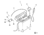
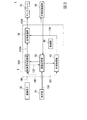
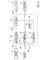
図1は、本発明の第1の実施形態の計測内視鏡装置1の外観を示している。図2は、計測内視鏡装置1のハードウェア構成を示している。図3は、計測内視鏡装置1の機能構成を示している。
(First embodiment)
FIG. 1 shows an appearance of a measurement endoscope apparatus 1 according to the first embodiment of the present invention. FIG. 2 shows a hardware configuration of the measurement endoscope apparatus 1. FIG. 3 shows a functional configuration of the measurement endoscope apparatus 1.

計測内視鏡装置1は、被検体を撮像し、画像から被検体の幾何学的特徴を計測する。検査者は、種々の被検体の観察と計測とを行うために、内視鏡挿入部の先端部に装着される光学アダプタの交換と、内蔵された計測処理プログラムの選択と、計測処理プログラムの追加とを行うことが可能である。以下では、計測の一例としてステレオ計測を行う場合について説明する。   The measurement endoscope apparatus 1 images a subject and measures a geometric feature of the subject from the image. In order to perform observation and measurement of various subjects, the examiner replaces the optical adapter attached to the distal end of the endoscope insertion portion, selects a built-in measurement processing program, and sets the measurement processing program. Can be added. Hereinafter, a case where stereo measurement is performed as an example of measurement will be described.

図1と図2とに示すように、計測内視鏡装置1は、ステレオ計測用の光学アダプタ2と、内視鏡挿入部3と、内視鏡ユニット7と、液晶モニタ6と、リモートコントローラ5と、コントロールユニット4とを有する。   As shown in FIG. 1 and FIG. 2, a measurement endoscope apparatus 1 includes an optical adapter 2 for stereo measurement, an endoscope insertion unit 3, an endoscope unit 7, a liquid crystal monitor 6, and a remote controller. 5 and a control unit 4.

光学アダプタ2は、視差を有する画像を取得するために所定距離だけ離間して配置された2つの光学系すなわち第1の対物光学系2Aと第2の対物光学系2Bとを有する。第1の対物光学系2Aと第2の対物光学系2Bとは、略円筒状のアダプタ本体2a内に配置されている。例えば、光学アダプタ2は、雌ねじなどが形成されたマウント部2bにより、内視鏡挿入部3の先端部に着脱可能に装着される。   The optical adapter 2 includes two optical systems, that is, a first objective optical system 2A and a second objective optical system 2B, which are arranged apart from each other by a predetermined distance in order to acquire an image having parallax. The first objective optical system 2A and the second objective optical system 2B are disposed in a substantially cylindrical adapter body 2a. For example, the optical adapter 2 is detachably attached to the distal end portion of the endoscope insertion portion 3 by a mount portion 2b in which a female screw or the like is formed.

第1の対物光学系2Aと第2の対物光学系2Bとの位置は、光学アダプタ2の軸方向に視野を有する直視タイプと、光学アダプタ2の側面方向に視野を有する側視タイプとで異なる。図1では、直視タイプにおける位置が示されている。このため、第1の対物光学系2Aと第2の対物光学系2Bとは、光軸が光学アダプタ2の軸方向に向いた状態で、光学アダプタ2の先端面に設けられた開口部の近傍に配置されている。また、光学アダプタ2の先端面には、アダプタ本体2a内に導光された照明光を被検体に向けて出射する照明窓2cが設けられている。光学アダプタ2は、デュアルレンズを有するステレオ光学系でなくてもよい。例えば、光学アダプタ2が、ステレオ画像を取得するプリズム等の光学系であっても同一の効果が得られる。また、光学アダプタ2にステレオ光学系が設けられているが、内視鏡挿入部3の先端部にステレオ光学系が設けられてもよい。   The positions of the first objective optical system 2 </ b> A and the second objective optical system 2 </ b> B are different between a direct-view type having a visual field in the axial direction of the optical adapter 2 and a side-view type having a visual field in the side surface direction of the optical adapter 2. . In FIG. 1, the position in the direct view type is shown. Therefore, the first objective optical system 2A and the second objective optical system 2B are in the vicinity of the opening provided on the front end surface of the optical adapter 2 in a state where the optical axis is directed in the axial direction of the optical adapter 2. Is arranged. In addition, an illumination window 2c that emits the illumination light guided into the adapter main body 2a toward the subject is provided on the distal end surface of the optical adapter 2. The optical adapter 2 may not be a stereo optical system having a dual lens. For example, the same effect can be obtained even if the optical adapter 2 is an optical system such as a prism that acquires a stereo image. Further, although the stereo optical system is provided in the optical adapter 2, the stereo optical system may be provided at the distal end portion of the endoscope insertion portion 3.

内視鏡挿入部3は、被検体の内部に挿入される。内視鏡挿入部3は、計測部分を撮像し、撮像信号100(図3参照)をコントロールユニット4に出力する。内視鏡挿入部3の先端部には、光学アダプタ2などの複数の光学アダプタに共通のマウント部が設けられている。このマウント部に各光学アダプタが装着可能である。内視鏡挿入部3の先端部の内部には、CCDなどの撮像素子30(図3参照)とライトガイドとが設けられている。撮像素子30は、光学アダプタ2の第1の対物光学系2Aと第2の対物光学系2Bとによって結像される像を撮像し、撮像信号100を生成する。ライトガイドは、照明光を被検体に照射する。   The endoscope insertion unit 3 is inserted into the subject. The endoscope insertion unit 3 images the measurement part and outputs an image signal 100 (see FIG. 3) to the control unit 4. A mount portion common to a plurality of optical adapters such as the optical adapter 2 is provided at the distal end portion of the endoscope insertion portion 3. Each optical adapter can be attached to the mount portion. An imaging element 30 (see FIG. 3) such as a CCD and a light guide are provided inside the distal end portion of the endoscope insertion portion 3. The imaging element 30 captures an image formed by the first objective optical system 2A and the second objective optical system 2B of the optical adapter 2 and generates an imaging signal 100. The light guide irradiates the subject with illumination light.

内視鏡挿入部3は、その先端部から基端部にわたって屈曲可能な細長い管状である。内視鏡挿入部3の内部には、撮像素子30の信号線とライトガイド本体とが配置され、さらに先端部の湾曲を操作するためのワイヤ機構などが配置されている。内視鏡挿入部3に光学アダプタ2が装着される場合、撮像素子30によって、視差を有する2つの像が取得される。本明細書では、視差を有する2つの像に対応する2つの画像を視差画像と呼ぶ。内視鏡挿入部3内部の信号線により撮像信号100がコントロールユニット4に伝送される。   The endoscope insertion portion 3 is an elongated tubular shape that can be bent from the distal end portion to the proximal end portion. Inside the endoscope insertion portion 3, the signal line of the image sensor 30 and the light guide main body are disposed, and further, a wire mechanism for operating the bending of the distal end portion is disposed. When the optical adapter 2 is attached to the endoscope insertion unit 3, two images having parallax are acquired by the imaging element 30. In this specification, two images corresponding to two images having parallax are referred to as parallax images. An imaging signal 100 is transmitted to the control unit 4 through a signal line inside the endoscope insertion portion 3.

内視鏡ユニット7は、照明用光源、電動湾曲駆動ユニット、およびEEPROM8などを有する。照明用光源は、内視鏡挿入部3のライトガイドに導光される照明光を発生する。電動湾曲駆動ユニットは、ワイヤ機構を駆動する。EEPROM8は、電動湾曲駆動ユニットを駆動する制御パラメータを記憶する。内視鏡ユニット7は、内視鏡挿入部3の基端部に接続されている。   The endoscope unit 7 includes an illumination light source, an electric bending drive unit, an EEPROM 8, and the like. The illumination light source generates illumination light that is guided to the light guide of the endoscope insertion portion 3. The electric bending drive unit drives the wire mechanism. The EEPROM 8 stores control parameters for driving the electric bending drive unit. The endoscope unit 7 is connected to the proximal end portion of the endoscope insertion portion 3.

液晶モニタ6は、コントロールユニット4から出力される表示用映像信号103A(図3参照)に基づいて、被検体の映像とその他の情報とを表示する。これらの映像と情報とは、それぞれ必要に応じて単独に表示される。またはこれらの映像と情報とは、合成されて表示される。ステレオ計測が行われる場合には、表示用映像信号103Aは2つの視差画像の一方または両方を含む。   The liquid crystal monitor 6 displays the video of the subject and other information based on the display video signal 103A (see FIG. 3) output from the control unit 4. These images and information are individually displayed as necessary. Alternatively, these images and information are combined and displayed. When stereo measurement is performed, the display video signal 103A includes one or both of two parallax images.

例えば、液晶モニタ6によって表示される、映像以外の情報は、リモートコントローラ5などの操作部31(図3参照)からの操作入力情報と、操作メニューと、操作用のグラフィカルユーザインタフェース(GUI)と、計測用情報104(図3参照)との少なくとも1つである。計測用情報104は、計測時に使用される照準の画像および計測結果などである。   For example, information other than video displayed on the liquid crystal monitor 6 includes operation input information from the operation unit 31 (see FIG. 3) such as the remote controller 5, an operation menu, and an operation graphical user interface (GUI). And at least one of the measurement information 104 (see FIG. 3). The measurement information 104 is an aiming image and a measurement result used at the time of measurement.

リモートコントローラ5は、ユーザが計測内視鏡装置1の操作を行うための操作部31である。リモートコントローラ5はコントロールユニット4に接続されている。例えば、リモートコントローラ5が受け付ける操作は、電源のオン/オフと、キャリブレーション設定に関する操作と、撮像動作に関する操作と、照明に関する操作と、内視鏡挿入部3の湾曲駆動の操作と、計測に関する操作と、単眼表示/双眼表示の選択操作と、記憶媒体などへの映像記録操作と、記憶媒体などに記録された映像の読み出し操作との少なくとも1つである。ユーザは、リモートコントローラ5を介してこれらの操作を行うことができる。   The remote controller 5 is an operation unit 31 for a user to operate the measurement endoscope apparatus 1. The remote controller 5 is connected to the control unit 4. For example, the operations accepted by the remote controller 5 include power on / off, operations related to calibration settings, operations related to imaging operations, operations related to illumination, operations for driving the bending of the endoscope insertion unit 3, and measurement. It is at least one of an operation, a monocular display / binocular display selection operation, a video recording operation to a storage medium, and a video reading operation recorded on the storage medium. The user can perform these operations via the remote controller 5.

コントロールユニット4は、計測内視鏡装置1を制御する。コントロールユニット4による制御は、映像に対する映像処理と計測のための演算処理とを含む。図2に示すように、コントロールユニット4は、ハードウェアとしては、CCU9(カメラコントロールユニット)と、CPU10と、ROM11と、RAM12と、各種の入出力インタフェースと、映像信号処理回路16とを有する。   The control unit 4 controls the measurement endoscope apparatus 1. Control by the control unit 4 includes video processing for video and arithmetic processing for measurement. As shown in FIG. 2, the control unit 4 includes a CCU 9 (camera control unit), a CPU 10, a ROM 11, a RAM 12, various input / output interfaces, and a video signal processing circuit 16 as hardware.

CCU9は、内視鏡挿入部3に設けられた撮像素子30の撮像を制御する。また、CCU9は、撮像素子30により取得された撮像信号100に対して、輝度レベル調整およびノイズ除去処理などの前処理を行う。CCU9は、前処理が行われた撮像信号100をNTSC信号などの映像信号に変換する。   The CCU 9 controls imaging of the imaging device 30 provided in the endoscope insertion unit 3. In addition, the CCU 9 performs preprocessing such as brightness level adjustment and noise removal processing on the imaging signal 100 acquired by the imaging device 30. The CCU 9 converts the pre-processed imaging signal 100 into a video signal such as an NTSC signal.

CPU10は、ROM11または外部記憶媒体44(図3参照)に記憶された制御用のプログラムをRAM12にロードし、そのプログラムに規定された処理を実行する。コントロールユニット4は、入出力インタフェースとして、制御インタフェース15と、カードインタフェース13と、外部機器インタフェース14とを有する。   The CPU 10 loads a control program stored in the ROM 11 or the external storage medium 44 (see FIG. 3) into the RAM 12, and executes processing defined in the program. The control unit 4 includes a control interface 15, a card interface 13, and an external device interface 14 as input / output interfaces.

制御インタフェース15は、リモートコントローラ5と、内視鏡ユニット7と、CCU9との間で動作制御を行うための通信を行う。リムーバブルの記憶媒体であるメモリカード18がカードインタフェース13に接続される。カードインタフェース13は、装置を動作させるためのプログラムのロードと、計測に必要な設定情報、計測結果情報、および画像情報などの記憶とに使用される。   The control interface 15 performs communication for performing operation control among the remote controller 5, the endoscope unit 7, and the CCU 9. A memory card 18 that is a removable storage medium is connected to the card interface 13. The card interface 13 is used for loading a program for operating the apparatus and storing setting information, measurement result information, and image information necessary for measurement.

USB機器等の外部機器が外部機器インタフェース14に接続される。図2ではパーソナルコンピュータ17が外部機器インタフェース14に着脱可能に接続される。外部機器インタフェース14は、計測内視鏡装置1とパーソナルコンピュータ17との間で情報の授受を行う。これによって、パーソナルコンピュータ17の表示モニタが情報を表示すること、およびリモートコントローラ5に代わってコントロールユニット4に対してユーザが各種操作入力を行うことが可能である。   An external device such as a USB device is connected to the external device interface 14. In FIG. 2, the personal computer 17 is detachably connected to the external device interface 14. The external device interface 14 exchanges information between the measurement endoscope apparatus 1 and the personal computer 17. As a result, the display monitor of the personal computer 17 can display information, and the user can input various operations to the control unit 4 instead of the remote controller 5.

このため、外部機器インタフェース14にパーソナルコンピュータ17が接続される場合、パーソナルコンピュータ17が液晶モニタ6とリモートコントローラ5との機能を有することができる。この結果、パーソナルコンピュータ17が、計測に関する制御、映像処理、および画像表示などを必要に応じて行うことができる。   Therefore, when the personal computer 17 is connected to the external device interface 14, the personal computer 17 can have the functions of the liquid crystal monitor 6 and the remote controller 5. As a result, the personal computer 17 can perform measurement-related control, video processing, image display, and the like as necessary.

映像信号処理回路16は、CCU9から供給された映像信号に対して、リモートコントローラ5により指定された映像処理を施すことにより、出力用映像信号101A(図3参照)と出力用映像信号102(図3参照)とを生成する。映像信号処理回路16は、必要に応じて出力用映像信号101Aと、CPU10によって生成される操作画面画像または計測用情報104とを合成する。映像信号処理回路16は、合成された映像信号を表示用映像信号103Aとして液晶モニタ6に出力する。映像信号処理回路16は、CCU9によって行われる前処理を映像処理として行ってもよい。   The video signal processing circuit 16 performs video processing designated by the remote controller 5 on the video signal supplied from the CCU 9 to thereby output an output video signal 101A (see FIG. 3) and an output video signal 102 (see FIG. 3). 3). The video signal processing circuit 16 synthesizes the output video signal 101A and the operation screen image or measurement information 104 generated by the CPU 10 as necessary. The video signal processing circuit 16 outputs the synthesized video signal to the liquid crystal monitor 6 as a display video signal 103A. The video signal processing circuit 16 may perform preprocessing performed by the CCU 9 as video processing.

図3を参照して、ステレオ計測に関する計測内視鏡装置1の構成を説明する。図3に示すように、計測内視鏡装置1は、撮像素子30と、操作部31(表示モード選択部)と、ディスプレイ33と、映像信号処理部34A(表示信号生成部)と、信号変換部38と、画像記憶部42と、計測処理部43と、制御部45とを有する。映像信号処理部34Aと、信号変換部38と、画像記憶部42と、計測処理部43と、制御部45とはコントロールユニット4に配置されている。   With reference to FIG. 3, the structure of the measurement endoscope apparatus 1 regarding stereo measurement is demonstrated. As shown in FIG. 3, the measurement endoscope apparatus 1 includes an imaging device 30, an operation unit 31 (display mode selection unit), a display 33, a video signal processing unit 34A (display signal generation unit), and a signal conversion. A unit 38, an image storage unit 42, a measurement processing unit 43, and a control unit 45. The video signal processing unit 34 </ b> A, the signal conversion unit 38, the image storage unit 42, the measurement processing unit 43, and the control unit 45 are arranged in the control unit 4.

撮像素子30は、第1の方向(縦方向)と、第1の方向に直交する第2の方向(横方向)とに2次元状に広がる矩形状の撮像面を有する。撮像素子30の撮像面の第2の方向の寸法は撮像素子30の撮像面の第1の方向の寸法よりも大きい。撮像素子30は撮像信号100を生成する。   The imaging element 30 has a rectangular imaging surface that extends two-dimensionally in a first direction (vertical direction) and a second direction (horizontal direction) orthogonal to the first direction. The dimension in the second direction of the imaging surface of the imaging element 30 is larger than the dimension in the first direction of the imaging surface of the imaging element 30. The image sensor 30 generates an image signal 100.

操作部31はリモートコントローラ5に対応する。操作部31は、ユーザによる計測等の操作を受け付ける。また、操作部31は、受け付けられた操作に基づいて、双眼表示モードと単眼表示モードとのいずれか1つを選択する。双眼表示モードは、第1の像に基づく第1の画像および第2の像に基づく第2の画像を同時にディスプレイ33に表示するモードである。第1の像と第2の像とは、光学アダプタ2の第1の対物光学系2Aと第2の対物光学系2Bとによって撮像素子30の撮像面に結像される。単眼表示モードは、第1の画像のみをディスプレイ33に表示するモードである。   The operation unit 31 corresponds to the remote controller 5. The operation unit 31 receives an operation such as measurement by a user. The operation unit 31 selects one of the binocular display mode and the monocular display mode based on the accepted operation. The binocular display mode is a mode in which the first image based on the first image and the second image based on the second image are simultaneously displayed on the display 33. The first image and the second image are formed on the imaging surface of the imaging device 30 by the first objective optical system 2A and the second objective optical system 2B of the optical adapter 2. The monocular display mode is a mode for displaying only the first image on the display 33.

ディスプレイ33は液晶モニタ6に対応する。ディスプレイ33は、第3の方向(縦方向)と、第3の方向に直交する第4の方向(横方向)とに2次元状に広がる矩形状の表示面を有する。ディスプレイ33の表示面の第4の方向の寸法はディスプレイ33の表示面の第3の方向の寸法よりも大きい。ディスプレイ33は、表示用映像信号103A(表示信号)に基づいて画像を表示する。ディスプレイ33は、双眼表示モードでは、第1の像に基づく第1の画像と第2の像に基づく第2の画像とを同時に表示する。ディスプレイ33は、単眼表示モードでは、第1の画像のみを表示する。   The display 33 corresponds to the liquid crystal monitor 6. The display 33 has a rectangular display surface that extends two-dimensionally in a third direction (vertical direction) and a fourth direction (horizontal direction) orthogonal to the third direction. The dimension of the display surface of the display 33 in the fourth direction is larger than the dimension of the display surface of the display 33 in the third direction. The display 33 displays an image based on the display video signal 103A (display signal). In the binocular display mode, the display 33 simultaneously displays a first image based on the first image and a second image based on the second image. The display 33 displays only the first image in the monocular display mode.

映像信号処理部34AはCCU9と映像信号処理回路16とに対応する。映像信号処理部34Aは、入力された撮像信号100を処理し、出力用映像信号101Aを生成する。出力用映像信号101Aは信号変換部38に出力される。   The video signal processing unit 34 </ b> A corresponds to the CCU 9 and the video signal processing circuit 16. The video signal processing unit 34A processes the input imaging signal 100 to generate an output video signal 101A. The output video signal 101A is output to the signal converter 38.

映像信号処理部34Aは、単眼表示モードが選択された場合、第1の画像における第2の方向がディスプレイ33の表示面の第3の方向に一致し、第1の画像における第1の方向がディスプレイ33の表示面の第4の方向に一致するように、かつ、単眼表示モードにおけるディスプレイ33上での第1の画像の表示領域が、双眼表示モードにおけるディスプレイ33上での第1の画像の表示領域よりも大きくなるように出力用映像信号101Aを生成する。   When the monocular display mode is selected, the video signal processing unit 34A matches the third direction of the display surface of the display 33 with the second direction in the first image, and the first direction in the first image is The display area of the first image on the display 33 in the monocular display mode so as to coincide with the fourth direction of the display surface of the display 33 is the first image on the display 33 in the binocular display mode. The output video signal 101A is generated so as to be larger than the display area.

映像信号処理部34Aは、双眼表示モードが選択された場合、第1の画像および第2の画像における第1の方向がディスプレイ33の表示面の第3の方向に一致し、第1の画像および第2の画像における第2の方向がディスプレイ33の表示面の第4の方向に一致するように出力用映像信号101Aを生成する。   When the binocular display mode is selected, the video signal processing unit 34A matches the first direction of the first image and the second image with the third direction of the display surface of the display 33, The output video signal 101 </ b> A is generated so that the second direction in the second image matches the fourth direction of the display surface of the display 33.

また、映像信号処理部34Aは、出力用映像信号102を生成し、出力用映像信号102を画像記憶部42に出力する。出力用映像信号101Aと出力用映像信号102とは、異なる信号とは限らず、同一の映像処理が施された同一の信号であってもよい。   The video signal processing unit 34 </ b> A generates the output video signal 102 and outputs the output video signal 102 to the image storage unit 42. The output video signal 101A and the output video signal 102 are not limited to different signals, and may be the same signal subjected to the same video processing.

信号変換部38は映像信号処理回路16に対応する。信号変換部38は、映像信号処理部34Aから出力された出力用映像信号101Aを表示用映像信号103Aとしてディスプレイ33に出力する。信号変換部38は、必要に応じて、出力用映像信号101Aに対して操作画面画像などの他の画像データを合成することにより、出力用映像信号101Aを表示用映像信号103Aに変換する。また、計測処理部43から計測用情報104が出力された場合、信号変換部38は、出力用映像信号101Aに対して計測用情報104を合成することにより表示用映像信号103Aを生成する。   The signal conversion unit 38 corresponds to the video signal processing circuit 16. The signal conversion unit 38 outputs the output video signal 101A output from the video signal processing unit 34A to the display 33 as the display video signal 103A. The signal conversion unit 38 converts the output video signal 101A into the display video signal 103A by combining other image data such as an operation screen image with the output video signal 101A as necessary. When the measurement information 104 is output from the measurement processing unit 43, the signal conversion unit 38 generates the display video signal 103A by combining the measurement information 104 with the output video signal 101A.

画像記憶部42はRAM12に対応する。画像記憶部42は、映像信号処理部34Aから出力される出力用映像信号102を画像データとして記憶する。画像記憶部42に記憶される画像データは、1フレームの静止画データまたは複数フレームのライブ画像のデータである。操作部31から画像記録の指示信号106が入力された場合、制御部45による制御に従って、画像データが画像記憶部42から読み出される。読み出された画像データは外部記憶媒体44に出力され、外部記憶媒体44に記憶される。   The image storage unit 42 corresponds to the RAM 12. The image storage unit 42 stores the output video signal 102 output from the video signal processing unit 34A as image data. The image data stored in the image storage unit 42 is one frame of still image data or a plurality of frames of live image data. When an image recording instruction signal 106 is input from the operation unit 31, image data is read from the image storage unit 42 in accordance with control by the control unit 45. The read image data is output to the external storage medium 44 and stored in the external storage medium 44.

計測処理部43は、画像記憶部42に記憶された画像データを用いて計測処理を行う。また、計測処理部43は、ユーザによる計測の操作に必要な計測用のGUI画像を生成する。計測処理部43は、周知のアルゴリズムによりステレオ計測を行う。例えば、操作部31によって、液晶モニタ6の表示画像上で計測点が入力されると、計測処理部43は、2つの視差画像の輝度情報に基づいてマッチング処理を行う。これにより、計測処理部43は、2つの視差画像の一方の計測点に対応する、2つの視差画像の他方の対応点の位置を算出する。さらに、計測処理部43は、計測点と対応点との位置に基づいて、三角測量の原理により計測点の3次元座標を算出する。   The measurement processing unit 43 performs measurement processing using the image data stored in the image storage unit 42. Further, the measurement processing unit 43 generates a measurement GUI image necessary for a measurement operation by the user. The measurement processing unit 43 performs stereo measurement using a known algorithm. For example, when a measurement point is input on the display image of the liquid crystal monitor 6 by the operation unit 31, the measurement processing unit 43 performs a matching process based on the luminance information of the two parallax images. Thereby, the measurement processing unit 43 calculates the position of the other corresponding point of the two parallax images corresponding to one measurement point of the two parallax images. Furthermore, the measurement processing unit 43 calculates the three-dimensional coordinates of the measurement points based on the triangulation principle based on the positions of the measurement points and the corresponding points.

ユーザは、リモートコントローラ5を介して、ディスプレイ33の画面上の照準を操作することにより計測点などを指定する。計測点などの情報は、計測入力情報107として計測処理部43に出力される。ステレオ計測の計測結果は、計測点のマークなどを含む計測用のGUI画像と共に、計測用情報104として、信号変換部38に出力される。計測用情報104は、信号変換部38によって出力用映像信号101Aに合成される。   The user designates a measurement point or the like by operating the aim on the screen of the display 33 via the remote controller 5. Information such as measurement points is output to the measurement processing unit 43 as measurement input information 107. The measurement result of the stereo measurement is output to the signal conversion unit 38 as measurement information 104 together with a measurement GUI image including measurement point marks and the like. The measurement information 104 is combined with the output video signal 101A by the signal converter 38.

制御部45は、CPU10と、ROM11と、RAM12とに対応する。ROM11に格納されている制御用のプログラムをCPU10が読み出してRAM12にロードし、プログラムに記述されている命令をCPU10が実行することにより、制御部45は各部の動作を制御する。図3では、図3が複雑にならないように、制御部45と各部とを結ぶ矢印が省略されている。   The control unit 45 corresponds to the CPU 10, the ROM 11, and the RAM 12. The CPU 10 reads out the control program stored in the ROM 11 and loads it into the RAM 12, and the CPU 10 executes instructions described in the program, whereby the control unit 45 controls the operation of each unit. In FIG. 3, arrows that connect the control unit 45 and each unit are omitted so that FIG. 3 is not complicated.

パーソナルコンピュータ17は、操作部31と、ディスプレイ33と、計測処理部43との機能を有していてもよい。   The personal computer 17 may have functions of the operation unit 31, the display 33, and the measurement processing unit 43.

図4を参照し、ステレオ計測の原理を説明する。ステレオ計測では、ステレオ光学アダプタが使用される。被写体像を2つの光学系で捉えたときの2つの光学測距点の座標に基づいて、三角測量の原理を使用して被写体の3次元座標を求めることで、計測が可能である。以下では、ステレオ計測により計測点の3次元座標を求める方法を説明する。左の光学中心63と右の光学中心64とを結ぶ線分の中点が原点Oとして定義される。また、右方向が正であるx軸と、下方向が正であるy軸とが定義される。また、光軸と平行に光学系から遠ざかる方向が正であるz軸が定義される。   The principle of stereo measurement will be described with reference to FIG. In stereo measurement, a stereo optical adapter is used. Measurement is possible by obtaining the three-dimensional coordinates of the subject using the principle of triangulation based on the coordinates of the two optical ranging points when the subject image is captured by the two optical systems. Below, the method to obtain | require the three-dimensional coordinate of a measurement point by stereo measurement is demonstrated. The midpoint of the line segment connecting the left optical center 63 and the right optical center 64 is defined as the origin O. In addition, an x-axis in which the right direction is positive and a y-axis in which the downward direction is positive are defined. Further, a z-axis is defined in which the direction away from the optical system in parallel with the optical axis is positive.

左の光学系と右の光学系とを介して得られた被写体像を含む画像に対して、三角測量の方法により、計測点60の3次元座標(X,Y,Z)が以下の(1)式〜(3)式で計算される。ただし、歪み補正が施された左の画像面の計測点61と、歪み補正が施された右の画像面の対応点62との2次元座標はそれぞれ、(X,Y)、(X,Y)である。これらの2次元座標の原点はそれぞれ、左の光学系と右の光学系との光軸と画像面との交点O、交点Oである。左の光学中心63と右の光学中心64との距離はDである。焦点距離はFである。t=D/(X−X)である。
X=t×X+D/2 ・・・(1)
Y=−t×Y ・・・(2)
Z=t×F ・・・(3)
With respect to the image including the subject image obtained through the left optical system and the right optical system, the three-dimensional coordinates (X, Y, Z) of the measurement point 60 are expressed by the following (1) by the triangulation method. ) To (3). However, the two-dimensional coordinates of the measurement point 61 on the left image plane subjected to distortion correction and the corresponding point 62 on the right image plane subjected to distortion correction are (X L , Y L ) and (X R 1 , Y R ). Each origin of these two-dimensional coordinates, the intersection O L between the optical axis and the image plane of the left optical system and the right optical system, which is the intersection O R. The distance between the left optical center 63 and the right optical center 64 is D. The focal length is F. t = D / (X R −X L ).
X = t × X R + D / 2 (1)
Y = −t × Y R (2)
Z = t × F (3)

上記のように画像面上での計測点61と対応点62との座標が決定されると、パラメータDとパラメータFとを用いて計測点60の3次元座標が求まる。いくつかの点の3次元座標を求めることによって、2点間の距離、2点を結ぶ線と1点の距離、面積、深さ、表面形状等の様々な計測が可能である。また、左の光学中心63または右の光学中心64から被写体までの距離(物体距離)を求めることも可能である。上記のステレオ計測を行うためには、内視鏡挿入部3の先端部と光学アダプタ2とを含む光学系の特性を示す光学データが必要である。例えば、マッチング処理および光学データの詳細は特開2004−49638号公報に記載されているので、その説明を省略する。   When the coordinates of the measurement point 61 and the corresponding point 62 on the image plane are determined as described above, the three-dimensional coordinates of the measurement point 60 are obtained using the parameter D and the parameter F. By obtaining three-dimensional coordinates of several points, various measurements such as the distance between two points, the distance between two points and the distance between one point, area, depth, and surface shape can be performed. It is also possible to obtain the distance (object distance) from the left optical center 63 or the right optical center 64 to the subject. In order to perform the above stereo measurement, optical data indicating the characteristics of the optical system including the distal end portion of the endoscope insertion portion 3 and the optical adapter 2 is necessary. For example, details of the matching process and the optical data are described in Japanese Patent Application Laid-Open No. 2004-49638, and a description thereof will be omitted.

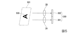
撮像素子30によって生成される撮像信号100について説明する。図5は、撮像の様子を示している。光学アダプタ2(ステレオ光学系)は、互いに異なる光軸を有する第1の対物光学系2Aおよび第2の対物光学系2Bを有する。図5に示すように、被写体500を含む撮像範囲501からの光が第1の対物光学系2Aと第2の対物光学系2Bとを通過し、撮像素子30が有する撮像面300に入射する。撮像面300は、第1の撮像領域301と第2の撮像領域302とを有する。第1の対物光学系2Aを通過した光が撮像面300の第1の撮像領域301に第1の像を形成する。また、第2の対物光学系2Bを通過した光が撮像面300の第2の撮像領域302に第2の像を形成する。   The image signal 100 generated by the image sensor 30 will be described. FIG. 5 shows a state of imaging. The optical adapter 2 (stereo optical system) includes a first objective optical system 2A and a second objective optical system 2B having different optical axes. As shown in FIG. 5, light from the imaging range 501 including the subject 500 passes through the first objective optical system 2 </ b> A and the second objective optical system 2 </ b> B and enters the imaging surface 300 included in the imaging element 30. The imaging surface 300 includes a first imaging area 301 and a second imaging area 302. The light that has passed through the first objective optical system 2 </ b> A forms a first image in the first imaging region 301 of the imaging surface 300. Further, the light that has passed through the second objective optical system 2 </ b> B forms a second image in the second imaging region 302 of the imaging surface 300.

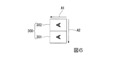
図6は、撮像素子30の光軸に平行に撮像面300を見た状態を示している。撮像面300は、矢印A1が示す第1の方向と、矢印A2が示す第2の方向とに2次元状に広がる矩形状である。第1の方向と第2の方向とは直交する。撮像面300の第2の方向の寸法は撮像面300の第1の方向の寸法よりも大きい。第1の撮像領域301は撮像面300において第2の方向の中央位置よりも第2の方向にある。第2の撮像領域302は撮像面300において第2の方向の中央位置よりも第2の方向と反対の方向にある。つまり、第1の撮像領域301と第2の撮像領域302とは、第2の方向に沿って並んでいる。第1の撮像領域301と第2の撮像領域302との第1の方向の寸法は第1の撮像領域301と第2の撮像領域302との第2の方向の寸法よりも大きい。   FIG. 6 shows a state in which the imaging surface 300 is viewed parallel to the optical axis of the imaging device 30. The imaging surface 300 has a rectangular shape that extends two-dimensionally in a first direction indicated by an arrow A1 and a second direction indicated by an arrow A2. The first direction and the second direction are orthogonal to each other. The dimension of the imaging surface 300 in the second direction is larger than the dimension of the imaging surface 300 in the first direction. The first imaging region 301 is located in the second direction with respect to the imaging surface 300 from the center position in the second direction. The second imaging region 302 is in a direction opposite to the second direction with respect to the center position in the second direction on the imaging surface 300. That is, the first imaging area 301 and the second imaging area 302 are arranged along the second direction. The dimension in the first direction of the first imaging area 301 and the second imaging area 302 is larger than the dimension in the second direction of the first imaging area 301 and the second imaging area 302.

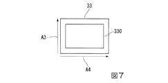
ディスプレイ33について説明する。図7は、ディスプレイ33を正面から見た状態を示している。ディスプレイ33は、矢印A3が示す第3の方向と、矢印A4が示す第4の方向とに2次元状に広がる矩形状の表示面330を有する。第3の方向と第4の方向とは直交する。表示面330の第4の方向の寸法は表示面330の第3の方向の寸法よりも大きい。   The display 33 will be described. FIG. 7 shows the display 33 as viewed from the front. The display 33 has a rectangular display surface 330 that extends two-dimensionally in a third direction indicated by an arrow A3 and a fourth direction indicated by an arrow A4. The third direction and the fourth direction are orthogonal to each other. The dimension of the display surface 330 in the fourth direction is larger than the dimension of the display surface 330 in the third direction.

第1の実施形態における各表示モードの設定と、各表示モードにおいてディスプレイ33に表示される画像の表示形態とについて説明する。計測内視鏡装置1は、ライブ画像の観察時の表示モードとして、単眼表示モードと双眼表示モードとの2つの表示モードを有する。例えば、操作部31は表示切替ボタンを有する。ユーザが操作部31の表示切替ボタンを操作することにより、2つの表示モードの選択と設定とが行われる。例えば、計測内視鏡装置1が起動した後、ユーザによってライブ画像の観察が最初に指定された場合、単眼表示モードが自動的に設定されるように、表示モードが予め決められている。   The setting of each display mode in the first embodiment and the display form of an image displayed on the display 33 in each display mode will be described. The measurement endoscope apparatus 1 has two display modes, a monocular display mode and a binocular display mode, as display modes when observing a live image. For example, the operation unit 31 has a display switching button. When the user operates the display switching button of the operation unit 31, two display modes are selected and set. For example, after the measurement endoscope apparatus 1 is activated, the display mode is determined in advance so that the monocular display mode is automatically set when observation of a live image is first designated by the user.

図8は、ライブ画像の観察時の計測内視鏡装置1の動作の手順を示している。上記のように、ライブ画像の観察では単眼表示モードが設定されているため、映像信号処理部34Aは、単眼表示用の出力用映像信号101Aを生成する(ステップS100)。単眼表示用の出力用映像信号101Aが生成された後、ディスプレイ33は、表示用映像信号103Aに基づいて画像を表示する(ステップS105)。ステップS105では、単眼表示が行われる。つまり、2つの視差画像の一方のみが表示される。   FIG. 8 shows a procedure of the operation of the measurement endoscope apparatus 1 when observing a live image. As described above, since the monocular display mode is set in the live image observation, the video signal processing unit 34A generates the output video signal 101A for monocular display (step S100). After the output video signal 101A for monocular display is generated, the display 33 displays an image based on the display video signal 103A (step S105). In step S105, monocular display is performed. That is, only one of the two parallax images is displayed.

ライブ画像の観察時に単眼表示モードが設定されている場合、ユーザが操作部31の表示モード切替ボタンを操作すると、操作部31から表示切替信号105が映像信号処理部34Aに入力される。映像信号処理部34Aは、表示切替信号105に基づいて、表示モードを双眼表示モードに設定する。一方、ライブ画像の観察時に双眼表示モードが設定されている場合、ユーザが操作部31の表示モード切替ボタンを操作すると、操作部31から表示切替信号105が映像信号処理部34Aに入力される。映像信号処理部34Aは、表示切替信号105に基づいて、表示モードを単眼表示モードに設定する。   When the monocular display mode is set when observing a live image, when the user operates the display mode switching button of the operation unit 31, the display switching signal 105 is input from the operation unit 31 to the video signal processing unit 34A. The video signal processing unit 34 </ b> A sets the display mode to the binocular display mode based on the display switching signal 105. On the other hand, when the binocular display mode is set during live image observation, when the user operates the display mode switching button of the operation unit 31, the display switching signal 105 is input from the operation unit 31 to the video signal processing unit 34A. Based on the display switching signal 105, the video signal processing unit 34A sets the display mode to the monocular display mode.

単眼表示が行われた後、映像信号処理部34Aは、表示モードが双眼表示モードであるか否かを判断する(ステップS110)。表示モードが双眼表示モードでない場合、ステップS100の処理が行われる。表示モードが双眼表示モードである場合、映像信号処理部34Aは、双眼表示用の出力用映像信号101Aを生成する(ステップS115)。双眼表示用の出力用映像信号101Aが生成された後、ディスプレイ33は、表示用映像信号103Aに基づいて画像を表示する(ステップS120)。ステップS120では、双眼表示が行われる。つまり、2つの視差画像が同時に表示される。双眼表示が行われた後、ステップS110の処理が行われる。   After the monocular display is performed, the video signal processing unit 34A determines whether or not the display mode is the binocular display mode (step S110). If the display mode is not the binocular display mode, the process of step S100 is performed. When the display mode is the binocular display mode, the video signal processing unit 34A generates the output video signal 101A for binocular display (step S115). After the output video signal 101A for binocular display is generated, the display 33 displays an image based on the display video signal 103A (step S120). In step S120, binocular display is performed. That is, two parallax images are displayed simultaneously. After the binocular display is performed, the process of step S110 is performed.

双眼表示の詳細について説明する。撮像素子30から出力される1フレーム分の撮像信号100には、第1の撮像領域301に入射した第1の像と、第2の撮像領域302に入射した第2の像とが含まれる。つまり、ステレオ光学系によって、同一の撮像タイミングで、視差を有する2つの像が撮像される。   Details of the binocular display will be described. The imaging signal 100 for one frame output from the imaging element 30 includes a first image incident on the first imaging area 301 and a second image incident on the second imaging area 302. That is, two images having parallax are captured by the stereo optical system at the same imaging timing.

図9は、双眼表示モードでディスプレイ33に表示される画像G100を示している。画像G100は、第1の像に基づく第1の画像G101と、第2の像に基づく第2の画像G102とを含む。第1の画像G101と第2の画像G102との第1の方向の寸法は、第1の画像G101と第2の画像G102との第2の方向の寸法よりも大きい。第1の画像G101と第2の画像G102とはディスプレイ33の表示面330の第4の方向に並んでいる。第1の画像G101と第2の画像G102とにおける第1の方向はディスプレイ33の表示面330の第3の方向に一致する。第1の画像G101と第2の画像G102とにおける第2の方向はディスプレイ33の表示面330の第4の方向に一致する。   FIG. 9 shows an image G100 displayed on the display 33 in the binocular display mode. The image G100 includes a first image G101 based on the first image and a second image G102 based on the second image. The dimension in the first direction between the first image G101 and the second image G102 is larger than the dimension in the second direction between the first image G101 and the second image G102. The first image G101 and the second image G102 are arranged in the fourth direction of the display surface 330 of the display 33. The first direction in the first image G101 and the second image G102 coincides with the third direction of the display surface 330 of the display 33. The second direction in the first image G101 and the second image G102 coincides with the fourth direction of the display surface 330 of the display 33.

双眼表示モードでは、ユーザは、画像が計測に適しているか否かを確認することができる。例えば、2つの視差画像の両方に被検体が含まれている画像は計測に適している。2つの視差画像の一方のみに異物が含まれている画像は計測に適していない。2つの視差画像において、計測対象の部分にハレーションが発生している画像は計測には適していない。ユーザは、上記の観点で画像を確認することができる。   In the binocular display mode, the user can check whether the image is suitable for measurement. For example, an image in which a subject is included in both of two parallax images is suitable for measurement. An image in which foreign matter is included in only one of the two parallax images is not suitable for measurement. In two parallax images, an image in which halation occurs in a measurement target portion is not suitable for measurement. The user can confirm the image from the above viewpoint.

単眼表示の詳細について説明する。図10は、図8のステップS100における計測内視鏡装置1の動作の手順を示している。映像信号処理部34Aは、撮像信号100から生成された映像信号に対して切り出し処理を行う(ステップS1000)。切り出し処理では、映像信号処理部34Aは、映像信号に含まれる2つの視差画像の1つのみを切り出す。切り出される視差画像は予め決められている。あるいは、切り出される視差画像はユーザによって選択される。以下では、左側の視差画像が第1の画像であり、第1の画像が切り出される場合を例に説明する。   Details of the monocular display will be described. FIG. 10 shows a procedure of the operation of the measurement endoscope apparatus 1 in step S100 of FIG. The video signal processing unit 34A performs a clipping process on the video signal generated from the imaging signal 100 (step S1000). In the cutout process, the video signal processing unit 34A cuts out only one of the two parallax images included in the video signal. The parallax image to be cut out is determined in advance. Alternatively, the parallax image to be cut out is selected by the user. Hereinafter, a case where the left parallax image is the first image and the first image is cut out will be described as an example.

切り出し処理が行われた後、映像信号処理部34Aは、映像信号に対して回転処理を行う(ステップS1005)。回転処理では、映像信号処理部34Aは、第1の画像における第2の方向がディスプレイ33の表示面330の第3の方向に一致し、第1の画像における第1の方向がディスプレイ33の表示面330の第4の方向に一致するように、第1の画像を90度回転させる。   After the cutout process is performed, the video signal processing unit 34A performs a rotation process on the video signal (step S1005). In the rotation processing, the video signal processing unit 34A causes the second direction in the first image to coincide with the third direction of the display surface 330 of the display 33, and the first direction in the first image is the display on the display 33. The first image is rotated 90 degrees so as to coincide with the fourth direction of the surface 330.

回転処理が行われた後、映像信号処理部34Aは、映像信号に対して拡大処理を行い、出力用映像信号101Aを生成する(ステップS1010)。拡大処理では、映像信号処理部34Aは、第1の画像の縦と横との長さの比を固定した状態で、第1の画像を最大の拡大率で拡大する。最大の拡大率とは、第1の画像がディスプレイ33の表示面330に収まるように、かつ、第1の画像がディスプレイ33の表示面330を最大限に使用するように、ディスプレイ33が第1の画像を表示することが可能となる拡大率を指す。拡大処理の結果、第1の画像はディスプレイ33の表示面330に最大限拡大されて表示される。また、単眼表示モードにおけるディスプレイ33上での第1の画像の表示領域が、双眼表示モードにおけるディスプレイ33上での第1の画像の表示領域よりも大きくなる。ステップS1010の処理が行われることにより、ステップS100の処理が終了する。   After the rotation process is performed, the video signal processing unit 34A performs an enlargement process on the video signal to generate an output video signal 101A (step S1010). In the enlargement process, the video signal processing unit 34A enlarges the first image at the maximum enlargement ratio in a state where the ratio between the length and the length of the first image is fixed. The maximum enlargement ratio means that the first image is fit on the display surface 330 of the display 33 and the display 33 uses the first display surface 330 of the display 33 to the maximum extent. The enlargement ratio at which the image can be displayed. As a result of the enlargement process, the first image is enlarged and displayed on the display surface 330 of the display 33 as much as possible. In addition, the display area of the first image on the display 33 in the monocular display mode is larger than the display area of the first image on the display 33 in the binocular display mode. When the process of step S1010 is performed, the process of step S100 ends.

図11は、単眼表示モードでディスプレイ33に表示される画像G110を示している。画像G110は、第1の像に基づく第1の画像G111を含む。第1の画像G111の第1の方向の寸法は、第1の画像G111の第2の方向の寸法よりも大きい。第1の画像G111における第1の方向はディスプレイ33の表示面330の第4の方向に一致する。第1の画像G111における第2の方向はディスプレイ33の表示面330の第3の方向に一致する。第1の画像G111の表示領域は、図9の第1の画像G101の表示領域よりも大きい。このため、ライブ画像の観察時に被検体に対する視認性が向上する。   FIG. 11 shows an image G110 displayed on the display 33 in the monocular display mode. The image G110 includes a first image G111 based on the first image. The dimension in the first direction of the first image G111 is larger than the dimension in the second direction of the first image G111. The first direction in the first image G111 coincides with the fourth direction of the display surface 330 of the display 33. The second direction in the first image G111 coincides with the third direction of the display surface 330 of the display 33. The display area of the first image G111 is larger than the display area of the first image G101 in FIG. For this reason, the visibility with respect to a subject improves at the time of observation of a live image.

計測内視鏡装置1の可搬性の向上のために、計測内視鏡装置1が小さいことが望ましい。このため、ディスプレイ33が小さいことが望ましい。また、ユーザがディスプレイ33から離れた場所で作業を行う場合には、ユーザがディスプレイ33に近い場所で作業を行う場合よりも被検体の視認が難しい。第1の実施形態では、ディスプレイ33の表示領域が有効に利用される。このため、ディスプレイ33が小さい場合、またはユーザがディスプレイ33から離れた場所で作業を行う場合に、視認性が損なわれない。   In order to improve the portability of the measurement endoscope apparatus 1, it is desirable that the measurement endoscope apparatus 1 is small. For this reason, it is desirable that the display 33 is small. Further, when the user performs work at a place away from the display 33, it is more difficult to visually recognize the subject than when the user performs work near the display 33. In the first embodiment, the display area of the display 33 is used effectively. For this reason, visibility is not impaired when the display 33 is small or when the user performs work away from the display 33.

第1の実施形態では、ライブ画像の観察時における単眼表示と双眼表示とについて説明した。上記の単眼表示と双眼表示とは計測時の画像表示に適用することが可能である。   In the first embodiment, the monocular display and the binocular display at the time of observing the live image have been described. The above monocular display and binocular display can be applied to image display during measurement.

第1の実施形態によれば、撮像素子30と、ステレオ光学系(光学アダプタ2)と、表示信号生成部(映像信号処理部34A)と、ディスプレイ33と、表示モード選択部(操作部31)と、を有する計測内視鏡装置1が構成される。   According to the first embodiment, the imaging device 30, the stereo optical system (optical adapter 2), the display signal generation unit (video signal processing unit 34A), the display 33, and the display mode selection unit (operation unit 31). The measurement endoscope apparatus 1 having the above is configured.

第1の実施形態では、単眼表示モードが選択された場合、第1の像に基づく第1の画像における第2の方向がディスプレイ33の表示面330の第3の方向に一致し、第1の画像における第1の方向がディスプレイ33の表示面330の第4の方向に一致するように、かつ、単眼表示モードにおけるディスプレイ33上での第1の画像の表示領域が、双眼表示モードにおけるディスプレイ33上での第1の画像の表示領域よりも大きくなるように出力用映像信号101Aが生成される。このため、視認性を向上させつつ、ディスプレイの表示領域をより有効に利用することができる。また、単眼表示モードでは、1つの視差画像における撮像範囲の全体を拡大して表示することができる。   In the first embodiment, when the monocular display mode is selected, the second direction in the first image based on the first image matches the third direction of the display surface 330 of the display 33, and the first The display direction of the first image on the display 33 in the monocular display mode is such that the first direction in the image matches the fourth direction of the display surface 330 of the display 33, and the display 33 in the binocular display mode. The output video signal 101A is generated so as to be larger than the display area of the first image. For this reason, the display area of the display can be used more effectively while improving the visibility. In the monocular display mode, the entire imaging range in one parallax image can be enlarged and displayed.

(第2の実施形態)
本発明の第2の実施形態の計測内視鏡装置1は、単眼表示モードと双眼表示モードとの両方において、像を回転させる。そして、計測内視鏡装置1は、単眼表示モードと双眼表示モードとで、像の向きを一致させる。
(Second Embodiment)
The measurement endoscope apparatus 1 according to the second embodiment of the present invention rotates an image in both the monocular display mode and the binocular display mode. The measurement endoscope apparatus 1 matches the image orientations in the monocular display mode and the binocular display mode.

第2の実施形態では、図3に示す構成が、図12に示す構成に変更される。図12は、計測内視鏡装置1の機能構成を示している。図12に示すように、計測内視鏡装置1は、撮像素子30と、操作部31(表示モード選択部)と、ディスプレイ33と、映像信号処理部34B(表示信号生成部)と、信号変換部38と、画像記憶部42と、計測処理部43と、制御部45とを有する。映像信号処理部34Bと、信号変換部38と、画像記憶部42と、計測処理部43と、制御部45とはコントロールユニット4に配置されている。   In the second embodiment, the configuration shown in FIG. 3 is changed to the configuration shown in FIG. FIG. 12 shows a functional configuration of the measurement endoscope apparatus 1. As shown in FIG. 12, the measurement endoscope apparatus 1 includes an image sensor 30, an operation unit 31 (display mode selection unit), a display 33, a video signal processing unit 34B (display signal generation unit), and a signal conversion. A unit 38, an image storage unit 42, a measurement processing unit 43, and a control unit 45. The video signal processing unit 34 </ b> B, the signal conversion unit 38, the image storage unit 42, the measurement processing unit 43, and the control unit 45 are arranged in the control unit 4.

図12に示す構成について、図3に示す構成と異なる点を説明する。映像信号処理部34Bは、双眼表示モードが選択された場合、第1の画像および第2の画像における第2の方向がディスプレイ33の表示面330の第3の方向に一致し、第1の画像および第2の画像における第1の方向がディスプレイ33の表示面330の第4の方向に一致するように出力用映像信号101Bを生成する。これによって、単眼表示モードにおいて表示される第1の画像における被写体の向きと、双眼表示モードにおいて表示される第1の画像における被写体の向きとがディスプレイ33上で同一になる。   The difference between the configuration shown in FIG. 12 and the configuration shown in FIG. 3 will be described. When the binocular display mode is selected, the video signal processing unit 34B matches the third direction of the display surface 330 of the display 33 with the second direction in the first image and the second image, and the first image The output video signal 101B is generated so that the first direction in the second image matches the fourth direction of the display surface 330 of the display 33. As a result, the orientation of the subject in the first image displayed in the monocular display mode and the orientation of the subject in the first image displayed in the binocular display mode are the same on the display 33.

さらに、映像信号処理部34Bは、双眼表示モードが選択された場合、第1の画像および第2の画像がディスプレイ33の表示面330の第3の方向に沿って並ぶように出力用映像信号101Bを生成する。信号変換部38は、出力用映像信号101Bに基づいて表示用映像信号103Bを生成する。   Furthermore, when the binocular display mode is selected, the video signal processing unit 34B outputs the output video signal 101B so that the first image and the second image are arranged along the third direction of the display surface 330 of the display 33. Is generated. The signal converter 38 generates a display video signal 103B based on the output video signal 101B.

上記以外の点については、図12に示す構成は図3に示す構成と同様である。   Except for the above, the configuration shown in FIG. 12 is the same as the configuration shown in FIG.

第2の実施形態におけるライブ画像の観察時の計測内視鏡装置1の動作は、図8と図10とに従う。第2の実施形態では、双眼表示モードにおける動作(図8のステップS115)が第1の実施形態と異なる。第2の実施形態における双眼表示の詳細について説明する。   The operation of the measurement endoscope apparatus 1 when observing a live image according to the second embodiment follows FIGS. 8 and 10. In the second embodiment, the operation in the binocular display mode (step S115 in FIG. 8) is different from that in the first embodiment. Details of the binocular display in the second embodiment will be described.

図13は、図8のステップS115における計測内視鏡装置1の動作の手順を示している。映像信号処理部34Bは、撮像信号100から生成された映像信号に対して回転処理を行う(ステップS1150)。回転処理では、映像信号処理部34Bは、映像信号に含まれる2つの視差画像を含む画像の全体を90度回転させる。つまり、映像信号処理部34Bは、単眼表示モードで表示される1つの視差画像の回転量と同一の回転量で、2つの視差画像を含む画像の全体を回転させる。回転方向は、単眼表示モードで表示される1つの視差画像の回転方向と同一である。ステップS1150の処理が行われることにより、ステップS115の処理が終了する。   FIG. 13 shows the procedure of the operation of the measurement endoscope apparatus 1 in step S115 of FIG. The video signal processing unit 34B performs a rotation process on the video signal generated from the imaging signal 100 (step S1150). In the rotation process, the video signal processing unit 34B rotates the entire image including two parallax images included in the video signal by 90 degrees. That is, the video signal processing unit 34B rotates the entire image including two parallax images by the same rotation amount as the rotation amount of one parallax image displayed in the monocular display mode. The rotation direction is the same as the rotation direction of one parallax image displayed in the monocular display mode. By performing the process of step S1150, the process of step S115 ends.

図14は、双眼表示モードでディスプレイ33に表示される画像G120を示している。画像G120は、第1の像に基づく第1の画像G121と、第2の像に基づく第2の画像G122とを含む。第1の画像G121と第2の画像G122との第1の方向の寸法は、第1の画像G121と第2の画像G122との第2の方向の寸法よりも大きい。第1の画像G121と第2の画像G122とはディスプレイ33の表示面330の第3の方向に並んでいる。第1の画像G121と第2の画像G122とにおける第2の方向はディスプレイ33の表示面330の第3の方向に一致する。第1の画像G121と第2の画像G122とにおける第1の方向はディスプレイ33の表示面330の第4の方向に一致する。第1の画像G121における被写体の向きは、図11に示す第1の画像G111における被写体の向きと同一である。   FIG. 14 shows an image G120 displayed on the display 33 in the binocular display mode. The image G120 includes a first image G121 based on the first image and a second image G122 based on the second image. The dimension in the first direction between the first image G121 and the second image G122 is larger than the dimension in the second direction between the first image G121 and the second image G122. The first image G121 and the second image G122 are arranged in the third direction of the display surface 330 of the display 33. The second direction in the first image G121 and the second image G122 coincides with the third direction of the display surface 330 of the display 33. The first direction in the first image G121 and the second image G122 matches the fourth direction of the display surface 330 of the display 33. The orientation of the subject in the first image G121 is the same as the orientation of the subject in the first image G111 shown in FIG.

2つの視差画像がディスプレイ33の表示面330の第3の方向に並んで表示されるため、ディスプレイ33上での第3の方向の表示領域の制約が大きい。このため、映像信号処理部34Bは、2つの視差画像がディスプレイ33の表示面330の第3の方向の表示領域に収まるように、2つの視差画像の拡大処理または縮小処理を行ってもよい。   Since the two parallax images are displayed side by side in the third direction of the display surface 330 of the display 33, the restriction of the display area in the third direction on the display 33 is large. For this reason, the video signal processing unit 34B may perform the enlargement process or the reduction process of the two parallax images so that the two parallax images fit within the display area in the third direction of the display surface 330 of the display 33.

第1の実施形態では、単眼表示モードにおける画像(図11)と双眼表示における画像(図9)とで像の向きが異なる。このため、第1の実施形態では、単眼表示モードと双眼表示モードとの間でモードが切り替わるときに像の向きが変化する。   In the first embodiment, the orientation of the image is different between the image in the monocular display mode (FIG. 11) and the image in the binocular display (FIG. 9). For this reason, in the first embodiment, the orientation of the image changes when the mode is switched between the monocular display mode and the binocular display mode.

第2の実施形態では、単眼表示モードにおける画像(図11)と双眼表示モードにおける画像(図14)とで像の向きが同一である。このため、第2の実施形態では、単眼表示モードと双眼表示モードとの間でモードが切り替わるときに像の向きが変化しない。この結果、モードの切替に伴うユーザの違和感を低減することができる。   In the second embodiment, the image orientation is the same for the image in the monocular display mode (FIG. 11) and the image in the binocular display mode (FIG. 14). For this reason, in the second embodiment, the orientation of the image does not change when the mode is switched between the monocular display mode and the binocular display mode. As a result, user discomfort associated with mode switching can be reduced.

(第3の実施形態)
本発明の第3の実施形態では、計測内視鏡装置1は、双眼表示モードで2つの視差画像を、ディスプレイ33の表示面330の第4の方向に沿って並べて表示する。
(Third embodiment)
In the third embodiment of the present invention, the measurement endoscope apparatus 1 displays two parallax images side by side along the fourth direction of the display surface 330 of the display 33 in the binocular display mode.

第3の実施形態では、図3に示す構成が、図15に示す構成に変更される。図15は、計測内視鏡装置1の機能構成を示している。図15に示すように、計測内視鏡装置1は、撮像素子30と、操作部31(表示モード選択部)と、ディスプレイ33と、映像信号処理部34C(表示信号生成部)と、信号変換部38と、画像記憶部42と、計測処理部43と、制御部45とを有する。映像信号処理部34Cと、信号変換部38と、画像記憶部42と、計測処理部43と、制御部45とはコントロールユニット4に配置されている。   In the third embodiment, the configuration shown in FIG. 3 is changed to the configuration shown in FIG. FIG. 15 shows a functional configuration of the measurement endoscope apparatus 1. As shown in FIG. 15, the measurement endoscope apparatus 1 includes an image sensor 30, an operation unit 31 (display mode selection unit), a display 33, a video signal processing unit 34C (display signal generation unit), and a signal conversion. A unit 38, an image storage unit 42, a measurement processing unit 43, and a control unit 45. The video signal processing unit 34 </ b> C, the signal conversion unit 38, the image storage unit 42, the measurement processing unit 43, and the control unit 45 are arranged in the control unit 4.

図15に示す構成について、図3に示す構成と異なる点を説明する。映像信号処理部34Cは、双眼表示モードが選択された場合、第1の画像および第2の画像における第2の方向がディスプレイ33の表示面330の第3の方向に一致し、第1の画像および第2の画像における第1の方向がディスプレイ33の表示面330の第4の方向に一致するように出力用映像信号101Cを生成する。これによって、単眼表示モードにおいて表示される第1の画像における被写体の向きと、双眼表示モードにおいて表示される第1の画像における被写体の向きとがディスプレイ33上で同一になる。   The configuration shown in FIG. 15 is different from the configuration shown in FIG. When the binocular display mode is selected, the video signal processing unit 34C matches the third direction of the display surface 330 of the display 33 with the second direction in the first image and the second image, and the first image The output video signal 101C is generated so that the first direction in the second image matches the fourth direction of the display surface 330 of the display 33. As a result, the orientation of the subject in the first image displayed in the monocular display mode and the orientation of the subject in the first image displayed in the binocular display mode are the same on the display 33.

さらに、映像信号処理部34Cは、双眼表示モードが選択された場合、第1の画像および第2の画像がディスプレイ33の表示面330の第4の方向に沿って並ぶように出力用映像信号101Cを生成する。信号変換部38は、出力用映像信号101Cに基づいて表示用映像信号103Cを生成する。   Furthermore, when the binocular display mode is selected, the video signal processing unit 34C outputs the video signal 101C for output so that the first image and the second image are arranged along the fourth direction of the display surface 330 of the display 33. Is generated. The signal converter 38 generates a display video signal 103C based on the output video signal 101C.

上記以外の点については、図15に示す構成は図3に示す構成と同様である。   Other than the above, the configuration shown in FIG. 15 is the same as the configuration shown in FIG.

第3の実施形態におけるライブ画像の観察時の計測内視鏡装置1の動作は、図8と図10とに従う。第3の実施形態では、双眼表示モードにおける動作(図8のステップS115)が第1の実施形態と異なる。第3の実施形態における双眼表示の詳細について説明する。   The operation of the measurement endoscope apparatus 1 when observing a live image in the third embodiment follows FIGS. 8 and 10. In the third embodiment, the operation in the binocular display mode (step S115 in FIG. 8) is different from that in the first embodiment. Details of the binocular display in the third embodiment will be described.

図16は、図8のステップS115における計測内視鏡装置1の動作の手順を示している。映像信号処理部34Cは、撮像信号100から生成された映像信号に対して回転処理を行う(ステップS1150)。回転処理は、第2の実施形態における回転処理と同様である。   FIG. 16 shows an operation procedure of the measurement endoscope apparatus 1 in step S115 of FIG. The video signal processing unit 34C performs a rotation process on the video signal generated from the imaging signal 100 (step S1150). The rotation process is the same as the rotation process in the second embodiment.

回転処理が行われた後、映像信号処理部34Cは、映像信号に対して切り出し処理を行う(ステップS1155)。切り出し処理では、映像信号処理部34Cは、映像信号に含まれる2つの視差画像を切り出す。   After the rotation process is performed, the video signal processing unit 34C performs a clipping process on the video signal (step S1155). In the cutout process, the video signal processing unit 34C cuts out two parallax images included in the video signal.

切り出し処理が行われた後、映像信号処理部34Cは、映像信号に対して配列処理を行う(ステップS1160)。配列処理では、映像信号処理部34Cは、2つの視差画像がディスプレイ33の表示面330の第4の方向に沿って並ぶように2つの視差画像を配列する。ステップS1160の処理が行われることにより、ステップS115の処理が終了する。   After the clipping process is performed, the video signal processing unit 34C performs an array process on the video signal (step S1160). In the arrangement process, the video signal processing unit 34C arranges the two parallax images so that the two parallax images are aligned along the fourth direction of the display surface 330 of the display 33. By performing the process of step S1160, the process of step S115 ends.

図17は、双眼表示モードでディスプレイ33に表示される画像G130を示している。画像G130は、第1の像に基づく第1の画像G131と、第2の像に基づく第2の画像G132とを含む。第1の画像G131と第2の画像G132との第1の方向の寸法は、第1の画像G131と第2の画像G132との第2の方向の寸法よりも大きい。第1の画像G131と第2の画像G132とはディスプレイ33の表示面330の第4の方向に並んでいる。第1の画像G131と第2の画像G132とにおける第2の方向はディスプレイ33の表示面330の第3の方向に一致する。第1の画像G131と第2の画像G132とにおける第1の方向はディスプレイ33の表示面330の第4の方向に一致する。第1の画像G131における被写体の向きは、図11に示す第1の画像G111における被写体の向きと同一である。   FIG. 17 shows an image G130 displayed on the display 33 in the binocular display mode. The image G130 includes a first image G131 based on the first image and a second image G132 based on the second image. The dimension in the first direction between the first image G131 and the second image G132 is larger than the dimension in the second direction between the first image G131 and the second image G132. The first image G131 and the second image G132 are arranged in the fourth direction of the display surface 330 of the display 33. The second direction in the first image G131 and the second image G132 coincides with the third direction of the display surface 330 of the display 33. The first direction in the first image G131 and the second image G132 coincides with the fourth direction of the display surface 330 of the display 33. The orientation of the subject in the first image G131 is the same as the orientation of the subject in the first image G111 shown in FIG.

2つの視差画像がディスプレイ33の表示面330の第4の方向に並んで表示されるため、ディスプレイ33上での第4の方向の表示領域の制約が大きい。このため、映像信号処理部34Cは、2つの視差画像がディスプレイ33の表示面330の第4の方向の表示領域に収まるように、2つの視差画像の拡大処理または縮小処理を行ってもよい。   Since the two parallax images are displayed side by side in the fourth direction of the display surface 330 of the display 33, the restriction on the display area in the fourth direction on the display 33 is large. For this reason, the video signal processing unit 34 </ b> C may perform the enlargement process or the reduction process of the two parallax images so that the two parallax images fit within the display area in the fourth direction of the display surface 330 of the display 33.

第3の実施形態では、単眼表示における画像(図11)と双眼表示における画像(図17)とで像の向きが同一である。このため、第3の実施形態では、単眼表示モードと双眼表示モードとの間でモードが切り替わるときに像の向きが変化しない。この結果、モードの切替に伴うユーザの違和感を低減することができる。   In the third embodiment, the image orientation is the same for an image in monocular display (FIG. 11) and an image in binocular display (FIG. 17). For this reason, in the third embodiment, the orientation of the image does not change when the mode is switched between the monocular display mode and the binocular display mode. As a result, user discomfort associated with mode switching can be reduced.

(第4の実施形態)
本発明の第4の実施形態では、計測内視鏡装置1は、双眼表示モードで表示される2つの視差画像において、計測に不要な視野領域の像を削除する。計測に不要な視野領域は、2つの視差画像の一方のみに写っている視野領域である。計測に不要な視野領域の像を表示する必要はない。このため、計測内視鏡装置1は、計測に不要な視野領域、すなわち2つの視差画像の一方のみに写っている視野領域の像を削除する。言い換えると、計測内視鏡装置1は、2つの視差画像の両方に共通して写っている視野領域の像を2つの視差画像から切り出す。単眼表示モードにおける視野領域よりも小さい視野領域の像を切り出すことによって、双眼表示モードにおいて2つの視差画像の拡大表示が可能である。あるいは、双眼表示モードにおいて2つの視差画像を単眼表示モードにおける視差画像よりも縮小する必要がある場合、縮小率をより小さくすることが可能である。
(Fourth embodiment)
In the fourth embodiment of the present invention, the measurement endoscope apparatus 1 deletes an image of a visual field area unnecessary for measurement in two parallax images displayed in the binocular display mode. A visual field area that is not necessary for measurement is a visual field area that appears in only one of the two parallax images. There is no need to display an image of a visual field area unnecessary for measurement. For this reason, the measurement endoscope apparatus 1 deletes an image of a visual field area that is not necessary for measurement, that is, an image of a visual field area that appears in only one of the two parallax images. In other words, the measurement endoscope apparatus 1 cuts out from the two parallax images an image of the visual field area that is common to both the two parallax images. By cutting out an image of a visual field area smaller than the visual field area in the monocular display mode, it is possible to enlarge and display two parallax images in the binocular display mode. Alternatively, when it is necessary to reduce two parallax images in the binocular display mode as compared with the parallax images in the monocular display mode, the reduction ratio can be further reduced.

第4の実施形態では、図3に示す構成が、図18に示す構成に変更される。図18は、計測内視鏡装置1の機能構成を示している。図18に示すように、計測内視鏡装置1は、撮像素子30と、操作部31(表示モード選択部)と、ディスプレイ33と、映像信号処理部34D(表示信号生成部)と、信号変換部38と、画像記憶部42と、計測処理部43と、制御部45とを有する。映像信号処理部34Dと、信号変換部38と、画像記憶部42と、計測処理部43と、制御部45とはコントロールユニット4に配置されている。   In the fourth embodiment, the configuration shown in FIG. 3 is changed to the configuration shown in FIG. FIG. 18 shows a functional configuration of the measurement endoscope apparatus 1. As shown in FIG. 18, the measurement endoscope apparatus 1 includes an imaging element 30, an operation unit 31 (display mode selection unit), a display 33, a video signal processing unit 34D (display signal generation unit), and a signal conversion. A unit 38, an image storage unit 42, a measurement processing unit 43, and a control unit 45. The video signal processing unit 34 </ b> D, the signal conversion unit 38, the image storage unit 42, the measurement processing unit 43, and the control unit 45 are arranged in the control unit 4.

図18に示す構成について、図3に示す構成と異なる点を説明する。映像信号処理部34Dは、双眼表示モードが選択された場合、第1の画像および第2の画像における第2の方向がディスプレイ33の表示面330の第3の方向に一致し、第1の画像および第2の画像における第1の方向がディスプレイ33の表示面330の第4の方向に一致するように出力用映像信号101Dを生成する。これによって、単眼表示モードにおいて表示される第1の画像における被写体の向きと、双眼表示モードにおいて表示される第1の画像における被写体の向きとがディスプレイ33上で同一になる。   The configuration shown in FIG. 18 will be described while referring to differences from the configuration shown in FIG. When the binocular display mode is selected, the video signal processing unit 34D matches the third direction of the display surface 330 of the display 33 with the second direction in the first image and the second image, and the first image The output video signal 101D is generated so that the first direction in the second image matches the fourth direction of the display surface 330 of the display 33. As a result, the orientation of the subject in the first image displayed in the monocular display mode and the orientation of the subject in the first image displayed in the binocular display mode are the same on the display 33.

さらに、映像信号処理部34Dは、双眼表示モードが選択された場合、第1の像から第1の視野領域の像を切り出し、第2の像から第2の視野領域の像を切り出すことにより出力用映像信号101Dを生成する。双眼表示モードにおける第1の視野領域と第2の視野領域とは、単眼表示モードにおける第1の像の第3の視野領域よりも小さい。第1の視野領域と第2の視野領域とは、第1の像と第2の像とにおける共通の視野領域である。つまり、映像信号処理部34Dは、第1の像において第2の像に写らない視野領域の像と、第2の像において第1の像に写らない視野領域の像とを削除する。信号変換部38は、出力用映像信号101Dに基づいて表示用映像信号103Dを生成する。   Furthermore, when the binocular display mode is selected, the video signal processing unit 34D cuts out the image of the first visual field from the first image and outputs the image of the second visual field from the second image. A video signal 101D is generated. The first visual field region and the second visual field region in the binocular display mode are smaller than the third visual field region of the first image in the monocular display mode. The first visual field region and the second visual field region are common visual field regions in the first image and the second image. That is, the video signal processing unit 34D deletes the image of the visual field area that does not appear in the second image in the first image and the image of the visual field area that does not appear in the first image in the second image. The signal converter 38 generates a display video signal 103D based on the output video signal 101D.

上記以外の点については、図18に示す構成は図3に示す構成と同様である。   Regarding the points other than the above, the configuration shown in FIG. 18 is the same as the configuration shown in FIG.

第4の実施形態におけるライブ画像の観察時の計測内視鏡装置1の動作は、図8と図10とに従う。第4の実施形態では、双眼表示モードにおける動作(図8のステップS115)が第1の実施形態と異なる。第4の実施形態における双眼表示の詳細について説明する。   The operation of the measurement endoscope apparatus 1 when observing a live image in the fourth embodiment follows FIGS. 8 and 10. In the fourth embodiment, the operation in the binocular display mode (step S115 in FIG. 8) is different from that in the first embodiment. Details of the binocular display in the fourth embodiment will be described.

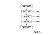
図19は、図8のステップS115における計測内視鏡装置1の動作の手順を示している。映像信号処理部34Dは、撮像信号100から生成された映像信号に対して切り出し処理を行う(ステップS1165)。図20は、双眼表示モードにおける処理の内容を示している。撮像信号100に基づく画像G140は、第1の像に基づく第1の画像G141と、第2の像に基づく第2の画像G142とを含む。切り出し処理では、映像信号処理部34Dは、第1の像から第1の視野領域の像I140を切り出し、第2の像から第2の視野領域の像I141を切り出す。第1の視野領域の像I140と第2の視野領域の像I141との第1の方向の寸法は、第1の視野領域の像I140と第2の視野領域の像I141との第2の方向の寸法よりも大きい。第1の視野領域と第2の視野領域とは、第1の像と第2の像とにおける共通の視野領域を含む。   FIG. 19 shows a procedure of the operation of the measurement endoscope apparatus 1 in step S115 of FIG. The video signal processing unit 34D performs a clipping process on the video signal generated from the imaging signal 100 (step S1165). FIG. 20 shows the contents of processing in the binocular display mode. The image G140 based on the imaging signal 100 includes a first image G141 based on the first image and a second image G142 based on the second image. In the cutout process, the video signal processing unit 34D cuts out the first visual field image I140 from the first image, and cuts out the second visual field image I141 from the second image. The dimension in the first direction of the first visual field image I140 and the second visual field image I141 is the second direction of the first visual field image I140 and the second visual field image I141. Is larger than the dimensions of The first visual field region and the second visual field region include a common visual field region in the first image and the second image.

第1の視野領域の像I140は第1の像よりも小さい。また、第2の視野領域の像I141は第2の像よりも小さい。単眼表示モードでは、第1の像の全体に対応する視野領域とほぼ一致する第3の視野領域の像が表示される。このため、第1の視野領域と第2の視野領域とは、単眼表示モードにおける第3の視野領域よりも小さい。映像信号処理部34Dは、切り出された第1の視野領域の像I140と第2の視野領域の像I141との拡大処理を行ってもよい。   The first viewing area image I140 is smaller than the first image. In addition, the image I141 in the second visual field is smaller than the second image. In the monocular display mode, an image of the third visual field area that substantially matches the visual field area corresponding to the entire first image is displayed. For this reason, the first visual field region and the second visual field region are smaller than the third visual field region in the monocular display mode. The video signal processing unit 34 </ b> D may perform enlargement processing on the cut-out first field-of-view image I140 and second field-of-view image I141.

切り出し処理が行われた後、映像信号処理部34Dは、映像信号に対して配列処理を行う(ステップS1170)。配列処理では、映像信号処理部34Dは、2つの視差画像が第2の方向に沿って並ぶように2つの視差画像を配列する。これによって、図20に示すように、第1の視野領域の像I140と第2の視野領域の像I141とが第2の方向に沿って並ぶ。   After the clipping process is performed, the video signal processing unit 34D performs an array process on the video signal (step S1170). In the arrangement process, the video signal processing unit 34D arranges the two parallax images so that the two parallax images are arranged in the second direction. As a result, as shown in FIG. 20, the image I140 of the first visual field and the image I141 of the second visual field are aligned along the second direction.

配列処理が行われた後、映像信号処理部34Dは、映像信号に対して回転処理を行う(ステップS1150)。回転処理は、第2の実施形態における回転処理と同様である。これによって、図20に示すように、第1の視野領域の像I140と第2の視野領域の像I141とがディスプレイ33の表示面330の第3の方向に沿って並ぶ。ステップS1150の処理が行われることにより、ステップS115の処理が終了する。   After the arrangement process is performed, the video signal processing unit 34D performs a rotation process on the video signal (step S1150). The rotation process is the same as the rotation process in the second embodiment. As a result, as shown in FIG. 20, the first visual field image I140 and the second visual field image I141 are arranged along the third direction of the display surface 330 of the display 33. By performing the process of step S1150, the process of step S115 ends.

図21は、第1の像と第2の像とにおける共通の視野領域を示している。図21では、第1の対物光学系2Aと第2の対物光学系2Bとの光軸における断面が示されている。線L100Aと線L100Bとは、撮像素子300の第1の撮像領域301に対応する視野を示している。線L101Aと線L101Bとは、撮像素子300の第2の撮像領域302に対応する視野を示している。位置Aは、計測可能な物体距離の遠点限界である。位置Bは、計測可能な物体距離の近点限界である。位置Aと位置Bとの間にある被写体に対して物体距離の計測が可能である。近点限界と遠点限界とは被写界深度に基づいて設定される値であり、それらの値はROM11等に予め記憶される。   FIG. 21 shows a common field of view in the first image and the second image. FIG. 21 shows a cross section along the optical axis of the first objective optical system 2A and the second objective optical system 2B. A line L100A and a line L100B indicate the field of view corresponding to the first imaging region 301 of the imaging device 300. A line L101A and a line L101B indicate the field of view corresponding to the second imaging region 302 of the imaging element 300. The position A is the far point limit of the measurable object distance. The position B is the near point limit of the measurable object distance. The object distance can be measured for the subject between the position A and the position B. The near point limit and the far point limit are values set based on the depth of field, and these values are stored in advance in the ROM 11 or the like.

ステレオ計測が可能な3次元領域R100は、計測可能な物体距離の範囲内にある。また、3次元領域R100は、2つの視差画像の両方に写る領域である。3次元領域R100は、第1の撮像領域301に対応する視野の限界である線L100Bと、第2の撮像領域302に対応する視野の限界である線L101Aとの間にある。位置Aにおいて、第1の像と第2の像とにおける共通の視野領域が最大である。第1の撮像領域301において位置Aの3次元領域R100の像が入射する第1の領域301Aの位置情報がROM11等に予め記憶される。また、第2の撮像領域302において位置Aの3次元領域R100の像が入射する第2の領域302Aの位置情報がROM11等に予め記憶される。例えば、第1の領域301Aと第2の領域302Aとは、設計値から算出される。第1の領域301Aと第2の領域302Aとは、カメラキャリブレーションにより求められたパラメータから算出されてもよい。   The three-dimensional region R100 in which stereo measurement is possible is within the range of the object distance that can be measured. The three-dimensional region R100 is a region that appears in both of the two parallax images. The three-dimensional region R100 is between the line L100B that is the limit of the visual field corresponding to the first imaging region 301 and the line L101A that is the limit of the visual field corresponding to the second imaging region 302. At position A, the common field of view in the first and second images is the largest. Position information of the first area 301A where the image of the three-dimensional area R100 at the position A enters in the first imaging area 301 is stored in advance in the ROM 11 or the like. In addition, position information of the second region 302A where the image of the three-dimensional region R100 at the position A is incident in the second imaging region 302 is stored in advance in the ROM 11 or the like. For example, the first area 301A and the second area 302A are calculated from design values. The first area 301A and the second area 302A may be calculated from parameters obtained by camera calibration.

図22は、双眼表示モードでディスプレイ33に表示される画像G140を示している。画像G140は、第1の像に基づく第1の画像G141と、第2の像に基づく第2の画像G142とを含む。第1の画像G141と第2の画像G142との第1の方向の寸法は、第1の画像G141と第2の画像G142との第2の方向の寸法よりも大きい。第1の画像G141と第2の画像G142とはディスプレイ33の表示面330の第3の方向に並んでいる。第1の画像G141と第2の画像G142とにおける第2の方向はディスプレイ33の表示面330の第3の方向に一致する。第1の画像G141と第2の画像G142とにおける第1の方向はディスプレイ33の表示面330の第4の方向に一致する。第1の画像G141における被写体の向きは、図11に示す第1の画像G111における被写体の向きと同一である。第1の画像G141と第2の画像G142との視野領域は、図11に示す第1の画像G111の視野領域よりも小さい。   FIG. 22 shows an image G140 displayed on the display 33 in the binocular display mode. The image G140 includes a first image G141 based on the first image and a second image G142 based on the second image. The dimension in the first direction between the first image G141 and the second image G142 is larger than the dimension in the second direction between the first image G141 and the second image G142. The first image G141 and the second image G142 are arranged in the third direction of the display surface 330 of the display 33. The second direction in the first image G141 and the second image G142 coincides with the third direction of the display surface 330 of the display 33. The first direction in the first image G141 and the second image G142 coincides with the fourth direction of the display surface 330 of the display 33. The orientation of the subject in the first image G141 is the same as the orientation of the subject in the first image G111 shown in FIG. The visual field area of the first image G141 and the second image G142 is smaller than the visual field area of the first image G111 shown in FIG.

図22では、第1の画像G141と第2の画像G142とがディスプレイ33の表示面330の第3の方向に沿って並ぶ。しかし、第1の画像G141と第2の画像G142とがディスプレイ33の表示面330の第4の方向に沿って並ぶように映像信号処理部34Dが処理を行ってもよい。   In FIG. 22, the first image G <b> 141 and the second image G <b> 142 are arranged along the third direction of the display surface 330 of the display 33. However, the video signal processing unit 34D may perform the process so that the first image G141 and the second image G142 are aligned along the fourth direction of the display surface 330 of the display 33.

単眼表示モードでは、ユーザに計測可能領域を知らせるために、計測内視鏡装置1は、切り出される視野領域を示す枠を第1の画像に重畳してもよい。   In the monocular display mode, in order to inform the user of the measurable area, the measurement endoscope apparatus 1 may superimpose a frame indicating the cut-out visual field area on the first image.

第4の実施形態では、単眼表示モードにおける画像(図11)と双眼表示モードにおける画像(図22)とで像の向きが同一である。このため、第4の実施形態では、単眼表示モードと双眼表示モードとの間でモードが切り替わるときに像の向きが変化しない。この結果、モードの切替に伴うユーザの違和感を低減することができる。   In the fourth embodiment, the image orientation is the same for the image in the monocular display mode (FIG. 11) and the image in the binocular display mode (FIG. 22). For this reason, in the fourth embodiment, the image orientation does not change when the mode is switched between the monocular display mode and the binocular display mode. As a result, user discomfort associated with mode switching can be reduced.

また、双眼表示モードで表示される2つの視差画像は共通の視野領域の像を有する。計測において、この共通の視野領域の像上のどの位置に対しても計測点の指定が可能である。   The two parallax images displayed in the binocular display mode have a common visual field image. In measurement, a measurement point can be specified for any position on the image of the common visual field area.

また、双眼表示モードでは第1の像の一部に基づく第1の画像と、第2の像の一部に基づく第2の画像とが表示される。このため、第1の画像と第2の画像との拡大処理が可能となり、視認性をより向上することができる。   In the binocular display mode, a first image based on a part of the first image and a second image based on a part of the second image are displayed. For this reason, enlargement processing of the first image and the second image is possible, and the visibility can be further improved.

(第5の実施形態)
本発明の第5の実施形態では、計測内視鏡装置1は、双眼表示モードで表示される2つの視差画像において、計測精度が低下する視野領域の像を削除する。計測精度が低下する視野領域は、第1の対物光学系2Aと第2の対物光学系2Bとの特性に応じた収差または口径食による光学性能の悪化が発生する領域である。例えば、計測精度が低下する視野領域は、視野領域の周縁部である。ユーザがその視野領域に計測点を指定することを回避するために、計測精度が低下する視野領域の像を表示する必要はない。
(Fifth embodiment)
In the fifth embodiment of the present invention, the measurement endoscope apparatus 1 deletes the image of the visual field area in which the measurement accuracy decreases in the two parallax images displayed in the binocular display mode. The visual field region where the measurement accuracy is lowered is a region where optical performance deteriorates due to aberration or vignetting according to the characteristics of the first objective optical system 2A and the second objective optical system 2B. For example, the visual field area where the measurement accuracy decreases is the peripheral edge of the visual field area. In order to avoid the user from designating a measurement point in the visual field area, it is not necessary to display an image of the visual field area in which the measurement accuracy decreases.

このため、計測内視鏡装置1は、計測精度が低下する視野領域、すなわち光学性能の悪化が発生する視野領域の像を削除する。言い換えると、計測内視鏡装置1は、2つの視差画像の両方に共通する、計測精度が低下しにくい視野領域の像を2つの視差画像から切り出す。単眼表示モードにおける視野領域よりも小さい視野領域の像を切り出すことによって、双眼表示モードにおいて2つの視差画像の拡大表示が可能である。あるいは、双眼表示モードにおいて2つの視差画像を単眼表示モードにおける視差画像よりも縮小する必要がある場合、縮小率をより小さくすることが可能である。   For this reason, the measurement endoscope apparatus 1 deletes the image of the visual field area where the measurement accuracy is lowered, that is, the visual field area where the optical performance is degraded. In other words, the measurement endoscope apparatus 1 cuts out from the two parallax images an image of the visual field area that is common to both of the two parallax images and in which the measurement accuracy is difficult to decrease. By cutting out an image of a visual field area smaller than the visual field area in the monocular display mode, it is possible to enlarge and display two parallax images in the binocular display mode. Alternatively, when it is necessary to reduce two parallax images in the binocular display mode as compared with the parallax images in the monocular display mode, the reduction ratio can be further reduced.

第5の実施形態では、図3に示す構成が、図23に示す構成に変更される。図23は、計測内視鏡装置1の機能構成を示している。図23に示すように、計測内視鏡装置1は、撮像素子30と、操作部31(表示モード選択部)と、ディスプレイ33と、映像信号処理部34E(表示信号生成部)と、信号変換部38と、画像記憶部42と、計測処理部43と、制御部45とを有する。映像信号処理部34Eと、信号変換部38と、画像記憶部42と、計測処理部43と、制御部45とはコントロールユニット4に配置されている。   In the fifth embodiment, the configuration shown in FIG. 3 is changed to the configuration shown in FIG. FIG. 23 shows a functional configuration of the measurement endoscope apparatus 1. As shown in FIG. 23, the measurement endoscope apparatus 1 includes an imaging device 30, an operation unit 31 (display mode selection unit), a display 33, a video signal processing unit 34E (display signal generation unit), and a signal conversion. A unit 38, an image storage unit 42, a measurement processing unit 43, and a control unit 45. The video signal processing unit 34 </ b> E, the signal conversion unit 38, the image storage unit 42, the measurement processing unit 43, and the control unit 45 are arranged in the control unit 4.

図23に示す構成について、図3に示す構成と異なる点を説明する。映像信号処理部34Eは、双眼表示モードが選択された場合、第1の画像および第2の画像における第2の方向がディスプレイ33の表示面330の第3の方向に一致し、第1の画像および第2の画像における第1の方向がディスプレイ33の表示面330の第4の方向に一致するように出力用映像信号101Eを生成する。これによって、単眼表示モードにおいて表示される第1の画像における被写体の向きと、双眼表示モードにおいて表示される第1の画像における被写体の向きとがディスプレイ33上で同一になる。   The configuration shown in FIG. 23 will be described while referring to differences from the configuration shown in FIG. When the binocular display mode is selected, the video signal processing unit 34E matches the third direction of the display surface 330 of the display 33 with the second direction in the first image and the second image, and the first image The output video signal 101E is generated so that the first direction in the second image coincides with the fourth direction of the display surface 330 of the display 33. As a result, the orientation of the subject in the first image displayed in the monocular display mode and the orientation of the subject in the first image displayed in the binocular display mode are the same on the display 33.

さらに、映像信号処理部34Eは、双眼表示モードが選択された場合、第1の像から第1の視野領域の像を切り出し、第2の像から第2の視野領域の像を切り出すことにより出力用映像信号101Eを生成する。双眼表示モードにおける第1の視野領域と第2の視野領域とは、単眼表示モードにおける第1の像の第3の視野領域よりも小さい。第1の視野領域は、第1の像における中央の領域であり、第2の視野領域は、第2の像における中央の領域である。言い換えると、第1の視野領域は、第1の像における中心を含む領域であり、第2の視野領域は、第2の像における中心を含む領域である。信号変換部38は、出力用映像信号101Eに基づいて表示用映像信号103Eを生成する。   Further, when the binocular display mode is selected, the video signal processing unit 34E cuts out an image of the first visual field from the first image and outputs an image of the second visual field from the second image. A video signal 101E is generated. The first visual field region and the second visual field region in the binocular display mode are smaller than the third visual field region of the first image in the monocular display mode. The first field area is a central area in the first image, and the second field area is a central area in the second image. In other words, the first visual field region is a region including the center in the first image, and the second visual field region is a region including the center in the second image. The signal converter 38 generates a display video signal 103E based on the output video signal 101E.

上記以外の点については、図23に示す構成は図3に示す構成と同様である。   Except for the above, the configuration shown in FIG. 23 is the same as the configuration shown in FIG.

第5の実施形態におけるライブ画像の観察時の計測内視鏡装置1の動作は、図8と図10とに従う。第5の実施形態では、双眼表示モードにおける動作(図8のステップS115)が第1の実施形態と異なる。双眼表示モードにおける動作は、図19に従う。   The operation of the measurement endoscope apparatus 1 when observing a live image in the fifth embodiment follows FIGS. 8 and 10. In the fifth embodiment, the operation in the binocular display mode (step S115 in FIG. 8) is different from that in the first embodiment. The operation in the binocular display mode follows FIG.

第5の実施形態では、映像信号処理部34Eは、図19のステップS1165において以下の処理を行う。映像信号処理部34Eは、第1の像から第1の視野領域の像を切り出し、第2の像から第2の視野領域の像を切り出す。第1の視野領域の像と第2の視野領域の像との第1の方向の寸法は、第1の視野領域の像と第2の視野領域の像との第2の方向の寸法よりも大きい。第1の視野領域は、第1の像における中央の領域であり、第2の視野領域は、第2の像における中央の領域である。   In the fifth embodiment, the video signal processing unit 34E performs the following processing in step S1165 of FIG. The video signal processing unit 34E cuts out an image of the first visual field from the first image, and cuts out an image of the second visual field from the second image. The dimension in the first direction between the image in the first field area and the image in the second field area is larger than the dimension in the second direction between the image in the first field area and the image in the second field area. large. The first field area is a central area in the first image, and the second field area is a central area in the second image.

第1の視野領域の像は第1の像よりも小さい。また、第2の視野領域の像は第2の像よりも小さい。単眼表示モードでは、第1の像の全体に対応する視野領域とほぼ一致する第3の視野領域の像が表示される。このため、第1の視野領域と第2の視野領域とは、単眼表示モードにおける第3の視野領域よりも小さい。映像信号処理部34Eは、切り出された第1の視野領域の像と第2の視野領域の像との拡大処理を行ってもよい。   The image in the first field area is smaller than the first image. In addition, the image of the second field area is smaller than the second image. In the monocular display mode, an image of the third visual field area that substantially matches the visual field area corresponding to the entire first image is displayed. For this reason, the first visual field region and the second visual field region are smaller than the third visual field region in the monocular display mode. The video signal processing unit 34E may perform an enlargement process on the cut out image of the first visual field and the image of the second visual field.

図19のステップS1170とステップS1150とでは、第4の実施形態における処理と同様の処理が行われる。   In step S1170 and step S1150 of FIG. 19, the same processing as that in the fourth embodiment is performed.

双眼表示モードでディスプレイ33に表示される画像は、図22における画像G140と同様である。例えば、第5の実施形態では、第1の画像と第2の画像とがディスプレイ33の表示面330の第3の方向に沿って並ぶ。しかし、第1の画像と第2の画像とがディスプレイ33の表示面330の第4の方向に沿って並ぶように映像信号処理部34Eが処理を行ってもよい。   An image displayed on the display 33 in the binocular display mode is the same as the image G140 in FIG. For example, in the fifth embodiment, the first image and the second image are arranged along the third direction of the display surface 330 of the display 33. However, the video signal processing unit 34E may perform the process so that the first image and the second image are aligned along the fourth direction of the display surface 330 of the display 33.

単眼表示モードでは、ユーザに計測可能領域を知らせるために、計測内視鏡装置1は、切り出される視野領域を示す枠を第1の画像に重畳してもよい。   In the monocular display mode, in order to inform the user of the measurable area, the measurement endoscope apparatus 1 may superimpose a frame indicating the cut-out visual field area on the first image.

第5の実施形態では、単眼表示モードにおける画像(図11)と双眼表示モードにおける画像(図22)とで像の向きが同一である。このため、第5の実施形態では、単眼表示モードと双眼表示モードとの間でモードが切り替わるときに像の向きが変化しない。この結果、モードの切替に伴うユーザの違和感を低減することができる。   In the fifth embodiment, the image orientation is the same for the image in the monocular display mode (FIG. 11) and the image in the binocular display mode (FIG. 22). For this reason, in the fifth embodiment, the orientation of the image does not change when the mode is switched between the monocular display mode and the binocular display mode. As a result, user discomfort associated with mode switching can be reduced.

また、双眼表示モードで表示される2つの視差画像は共通の視野領域の像を有する。計測において、この共通の視野領域の像上のどの位置に対しても計測点の指定が可能である。この共通の視野領域は、計測精度が低下する領域を含まないので、精度が高い計測結果を得ることができる。   The two parallax images displayed in the binocular display mode have a common visual field image. In measurement, a measurement point can be specified for any position on the image of the common visual field area. Since this common visual field region does not include a region where the measurement accuracy decreases, a measurement result with high accuracy can be obtained.

また、双眼表示モードでは第1の像の一部に基づく第1の画像と、第2の像の一部に基づく第2の画像とが表示される。このため、第1の画像と第2の画像との拡大処理が可能となる。あるいは、第1の画像と第2の画像との縮小率が小さくなる。この結果、視認性をより向上することができる。   In the binocular display mode, a first image based on a part of the first image and a second image based on a part of the second image are displayed. For this reason, enlargement processing of the first image and the second image is possible. Alternatively, the reduction ratio between the first image and the second image is reduced. As a result, the visibility can be further improved.

(第6の実施形態)
本発明の第6の実施形態では、双眼表示モードで表示される2つの視差画像の視野領域は、単眼表示モードにおいてユーザによって指定された計測点を含む。計測では、少なくともユーザによって指定された全ての計測点を含む領域が表示されることが重要である。その他の領域については計測処理に対してあまり影響がないため、その他の領域は表示されなくてもよい。
(Sixth embodiment)
In the sixth embodiment of the present invention, the visual field areas of the two parallax images displayed in the binocular display mode include measurement points designated by the user in the monocular display mode. In measurement, it is important to display an area including at least all measurement points designated by the user. The other areas do not have much influence on the measurement process, and the other areas do not need to be displayed.

このため、計測内視鏡装置1は、少なくともユーザによって指定された全ての計測点を含む矩形状の領域であって、単眼表示モードで表示される視野領域よりも小さい視野領域の像を切り出して表示する。単眼表示モードにおける視野領域よりも小さい視野領域の像を切り出すことによって、双眼表示モードにおいて2つの視差画像の拡大表示が可能である。あるいは、双眼表示モードにおいて2つの視差画像を単眼表示モードにおける視差画像よりも縮小する必要がある場合、縮小率をより小さくすることが可能である。   For this reason, the measurement endoscope apparatus 1 cuts out an image of a rectangular area including at least all measurement points designated by the user and smaller than the visual area displayed in the monocular display mode. indicate. By cutting out an image of a visual field area smaller than the visual field area in the monocular display mode, it is possible to enlarge and display two parallax images in the binocular display mode. Alternatively, when it is necessary to reduce two parallax images in the binocular display mode as compared with the parallax images in the monocular display mode, the reduction ratio can be further reduced.

第6の実施形態では、計測における単眼表示モードと双眼表示モードとの動作を説明する。また、単眼表示モードと双眼表示モードとの両方において、ディスプレイ33に静止画像が表示される例を説明する。また、2点間の距離を測定する2点間計測の例を説明する。   In the sixth embodiment, operations in the monocular display mode and the binocular display mode in measurement will be described. An example in which a still image is displayed on the display 33 in both the monocular display mode and the binocular display mode will be described. An example of measurement between two points for measuring the distance between two points will be described.

第6の実施形態では、図3に示す構成が、図24に示す構成に変更される。図24は、計測内視鏡装置1の機能構成を示している。図24に示すように、計測内視鏡装置1は、撮像素子30と、操作部31(表示モード選択部)と、ディスプレイ33と、映像信号処理部34F(表示信号生成部)と、信号変換部38と、画像記憶部42と、計測処理部43と、制御部45とを有する。映像信号処理部34Fと、信号変換部38と、画像記憶部42と、計測処理部43と、制御部45とはコントロールユニット4に配置されている。   In the sixth embodiment, the configuration shown in FIG. 3 is changed to the configuration shown in FIG. FIG. 24 shows a functional configuration of the measurement endoscope apparatus 1. As shown in FIG. 24, the measurement endoscope apparatus 1 includes an imaging element 30, an operation unit 31 (display mode selection unit), a display 33, a video signal processing unit 34F (display signal generation unit), and a signal conversion. A unit 38, an image storage unit 42, a measurement processing unit 43, and a control unit 45. The video signal processing unit 34 </ b> F, the signal conversion unit 38, the image storage unit 42, the measurement processing unit 43, and the control unit 45 are arranged in the control unit 4.

図24に示す構成について、図3に示す構成と異なる点を説明する。映像信号処理部34Fは、双眼表示モードが選択された場合、第1の画像および第2の画像における第2の方向がディスプレイ33の表示面330の第3の方向に一致し、第1の画像および第2の画像における第1の方向がディスプレイ33の表示面330の第4の方向に一致するように出力用映像信号101Fを生成する。これによって、単眼表示モードにおいて表示される第1の画像における被写体の向きと、双眼表示モードにおいて表示される第1の画像における被写体の向きとがディスプレイ33上で同一になる。   The configuration shown in FIG. 24 will be described while referring to differences from the configuration shown in FIG. When the binocular display mode is selected, the video signal processing unit 34F matches the third direction of the display surface 330 of the display 33 with the second direction in the first image and the second image, and the first image The output video signal 101F is generated so that the first direction in the second image matches the fourth direction of the display surface 330 of the display 33. As a result, the orientation of the subject in the first image displayed in the monocular display mode and the orientation of the subject in the first image displayed in the binocular display mode are the same on the display 33.

さらに、映像信号処理部34Fは、双眼表示モードが選択された場合、第1の像から第1の視野領域の像を切り出し、第2の像から第2の視野領域の像を切り出すことにより出力用映像信号101Fを生成する。双眼表示モードにおける第1の視野領域と第2の視野領域とは、単眼表示モードにおける第1の像の第3の視野領域よりも小さい。第1の視野領域と第2の視野領域との一方は、第1の像と第2の像との一方においてユーザによって指定された第1の位置を含む視野領域であり、第1の視野領域と第2の視野領域との他方は、第1の像と第2の像との他方において第1の位置に対応する第2の位置を含む視野領域である。例えば、第1の視野領域が、第1の像においてユーザによって指定された第1の位置を含む場合、第2の視野領域は、第2の像において第1の位置に対応する第2の位置を含む。第1の位置は、ユーザによって指定された計測点の位置である。信号変換部38は、出力用映像信号101Fに基づいて表示用映像信号103Fを生成する。   Further, when the binocular display mode is selected, the video signal processing unit 34F cuts out the first visual field image from the first image, and cuts out the second visual field image from the second image. A video signal for use 101F is generated. The first visual field region and the second visual field region in the binocular display mode are smaller than the third visual field region of the first image in the monocular display mode. One of the first field area and the second field area is a field area including a first position designated by the user in one of the first image and the second image, and the first field area And the other of the second visual field region is a visual field region including a second position corresponding to the first position in the other of the first image and the second image. For example, if the first field of view includes a first position specified by the user in the first image, the second field of view corresponds to the second position corresponding to the first position in the second image. including. The first position is the position of the measurement point designated by the user. The signal converter 38 generates a display video signal 103F based on the output video signal 101F.

上記以外の点については、図24に示す構成は図3に示す構成と同様である。   Regarding the points other than the above, the configuration shown in FIG. 24 is the same as the configuration shown in FIG.

図25は、計測時の計測内視鏡装置1の動作の手順を示している。計測内視鏡装置1は、計測時の表示モードとして、単眼表示モードと双眼表示モードとの2つの表示モードを有する。例えば、計測内視鏡装置1が起動した後、ユーザによって計測の実行が指定された場合、単眼表示モードが自動的に設定されるように、表示モードが予め決められている。このため、計測が開始されたとき、映像信号処理部34Fは、単眼表示用の出力用映像信号101Fを生成する(ステップS200)。ステップS200の処理は、図8のステップS100の処理と同様である。単眼表示用の出力用映像信号101Fが生成された後、ディスプレイ33は、表示用映像信号103Fに基づいて画像を表示する(ステップS205)。ステップS205では、単眼表示が行われる。つまり、2つの視差画像の一方のみが表示される。   FIG. 25 shows an operation procedure of the measurement endoscope apparatus 1 at the time of measurement. The measurement endoscope apparatus 1 has two display modes, a monocular display mode and a binocular display mode, as display modes at the time of measurement. For example, after the measurement endoscope apparatus 1 is activated, when the execution of measurement is designated by the user, the display mode is determined in advance so that the monocular display mode is automatically set. For this reason, when measurement is started, the video signal processing unit 34F generates an output video signal 101F for monocular display (step S200). The process of step S200 is the same as the process of step S100 of FIG. After the output video signal 101F for monocular display is generated, the display 33 displays an image based on the display video signal 103F (step S205). In step S205, monocular display is performed. That is, only one of the two parallax images is displayed.

単眼表示が行われた後、ユーザが操作部31を介して2つの計測点を指定する。2つの計測点の座標は、計測入力情報107として計測処理部43に出力される(ステップS210)。   After monocular display is performed, the user designates two measurement points via the operation unit 31. The coordinates of the two measurement points are output to the measurement processing unit 43 as measurement input information 107 (step S210).

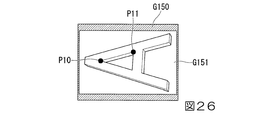
図26は、単眼表示モードでディスプレイ33に表示される画像G150を示している。画像G150は、第1の像に基づく第1の画像G151を含む。第1の画像G151において、ユーザによって計測点P10と計測点P11とが指定される。   FIG. 26 shows an image G150 displayed on the display 33 in the monocular display mode. The image G150 includes a first image G151 based on the first image. In the first image G151, the measurement point P10 and the measurement point P11 are designated by the user.

2つの計測点が指定された後、計測処理部43は、2つの計測点の座標をRAM12に記憶させる(ステップS215)。ステップS215で記憶される計測点の座標は第1の画像上の2次元座標である。2つの計測点の座標が記憶された後、映像信号処理部34Fは、双眼表示用の出力用映像信号101Fを生成する(ステップS220)。双眼表示用の出力用映像信号101Fが生成された後、ディスプレイ33は、表示用映像信号103Fに基づいて画像を表示する(ステップS225)。ステップS225では、双眼表示が行われる。つまり、2つの視差画像が同時に表示される。   After the two measurement points are designated, the measurement processing unit 43 stores the coordinates of the two measurement points in the RAM 12 (step S215). The coordinates of the measurement points stored in step S215 are two-dimensional coordinates on the first image. After the coordinates of the two measurement points are stored, the video signal processing unit 34F generates an output video signal 101F for binocular display (step S220). After the output video signal 101F for binocular display is generated, the display 33 displays an image based on the display video signal 103F (step S225). In step S225, binocular display is performed. That is, two parallax images are displayed simultaneously.

双眼表示が行われた後、計測処理部43は計測処理を行う(ステップS230)。ステップS230では、計測処理部43は、2つの計測点に対応する3次元座標を算出し、算出された3次元座標に基づいて2点間の距離を算出する。また、ステップS230では、計測結果が表示される。ステップS230の処理が行われることにより、計測が終了する。   After the binocular display is performed, the measurement processing unit 43 performs a measurement process (step S230). In step S230, the measurement processing unit 43 calculates three-dimensional coordinates corresponding to the two measurement points, and calculates a distance between the two points based on the calculated three-dimensional coordinates. In step S230, the measurement result is displayed. The measurement ends when the process of step S230 is performed.

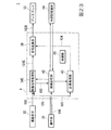
双眼表示の詳細について説明する。図27は、図25のステップS220における計測内視鏡装置1の動作の手順を示している。映像信号処理部34Fは、2つの計測点の座標をRAM12から読み出す(ステップS2200)。   Details of the binocular display will be described. FIG. 27 shows a procedure of the operation of the measurement endoscope apparatus 1 in step S220 of FIG. The video signal processing unit 34F reads the coordinates of the two measurement points from the RAM 12 (step S2200).

2つの計測点の座標がRAM12から読み出された後、映像信号処理部34Fは、2つの計測点の座標に基づいて第1の画像から領域を切り出す(ステップS2205)。例えば、ステップS2205で第1の画像から切り出される領域は、2つの計測点の座標を含む所定の大きさの領域である。この領域は、ユーザが2つの計測点を確認可能な最低限の領域であればよい。ステップS2205で第1の画像から切り出される領域は、1つのみの計測点の座標に基づく領域であってもよい。あるいは、ステップS2205で第1の画像から切り出される領域は、1つまたは2つの計測点を基準とする領域に基づく領域であってもよい。   After the coordinates of the two measurement points are read from the RAM 12, the video signal processing unit 34F cuts out an area from the first image based on the coordinates of the two measurement points (step S2205). For example, the region cut out from the first image in step S2205 is a region having a predetermined size including the coordinates of two measurement points. This area may be a minimum area where the user can confirm two measurement points. The region cut out from the first image in step S2205 may be a region based on the coordinates of only one measurement point. Alternatively, the region cut out from the first image in step S2205 may be a region based on a region based on one or two measurement points.

第1の画像から領域が切り出された後、映像信号処理部34Fは、第1の画像における第2の方向がディスプレイ33の表示面330の第3の方向に一致し、第1の画像における第1の方向がディスプレイ33の表示面330の第4の方向に一致するように、切り出された第1の画像の領域を90度回転させる(ステップS2210)。   After the region is cut out from the first image, the video signal processing unit 34F matches the third direction of the display surface 330 of the display 33 with the second direction in the first image, and the second direction in the first image. The region of the cut out first image is rotated 90 degrees so that the direction of 1 coincides with the fourth direction of the display surface 330 of the display 33 (step S2210).

第1の画像の領域の回転が行われた後、映像信号処理部34Fは、2つの計測点の座標をRAM12から読み出す(ステップS2215)。2つの計測点の座標がRAM12から読み出された後、映像信号処理部34Fは、2つの計測点の座標に対応する、第2の画像上の対応点の座標を算出するための探索範囲を算出する(ステップS2220)。例えば、ステップS2220では、映像信号処理部34Fは、第2の画像において、第1の画像の2つの計測点の座標に幾何学的に対応する位置の線(エピポーラライン)を基準に探索範囲を算出する。   After the first image area is rotated, the video signal processing unit 34F reads the coordinates of the two measurement points from the RAM 12 (step S2215). After the coordinates of the two measurement points are read from the RAM 12, the video signal processing unit 34F calculates a search range for calculating the coordinates of the corresponding points on the second image corresponding to the coordinates of the two measurement points. Calculate (step S2220). For example, in step S2220, the video signal processing unit 34F sets a search range on the basis of a line (epipolar line) at a position geometrically corresponding to the coordinates of two measurement points of the first image in the second image. calculate.

探索範囲が算出された後、映像信号処理部34Fは、第2の画像の探索範囲において、2つの計測点の座標に対応する座標を算出する(ステップS2225)。ステップS2225で算出される座標は第2の画像上の対応点の座標である。また、ステップS2225の処理は、いわゆるマッチング処理である。   After the search range is calculated, the video signal processing unit 34F calculates coordinates corresponding to the coordinates of the two measurement points in the search range of the second image (step S2225). The coordinates calculated in step S2225 are the coordinates of corresponding points on the second image. Further, the process of step S2225 is a so-called matching process.

対応点の座標が算出された後、映像信号処理部34Fは、ステップS2220で算出された探索範囲を含む領域を第2の画像から切り出す(ステップS2230)。ステレオマッチングの誤対応が起きていないこと等をユーザが確認できるように、ステップS2230では探索範囲の全体を含む領域が第2の画像から切り出されることが望ましい。   After the coordinates of the corresponding points are calculated, the video signal processing unit 34F cuts out a region including the search range calculated in step S2220 from the second image (step S2230). In step S2230, it is desirable that a region including the entire search range is cut out from the second image so that the user can confirm that no stereo matching error has occurred.

第2の画像から領域が切り出された後、映像信号処理部34Fは、第2の画像における第2の方向がディスプレイ33の表示面330の第3の方向に一致し、第2の画像における第1の方向がディスプレイ33の表示面330の第4の方向に一致するように、切り出された第2の画像の領域を90度回転させる(ステップS2235)。   After the region is cut out from the second image, the video signal processing unit 34F matches the third direction of the display surface 330 of the display 33 with the second direction in the second image, and the second direction in the second image. The region of the cut out second image is rotated 90 degrees so that the direction of 1 coincides with the fourth direction of the display surface 330 of the display 33 (step S2235).

第2の画像の領域の回転が行われた後、映像信号処理部34Fは、第1の画像および第2の画像がディスプレイ33の表示面330の第3の方向に沿って並ぶように出力用映像信号101Fを生成する(ステップS2240)。ステップS2240の処理が行われることにより、ステップS220の処理が終了する。   After the rotation of the area of the second image is performed, the video signal processing unit 34F outputs the first image and the second image so that the first image and the second image are aligned along the third direction of the display surface 330 of the display 33. The video signal 101F is generated (step S2240). By performing the process of step S2240, the process of step S220 ends.

図28は、双眼表示モードでディスプレイ33に表示される画像G160を示している。画像G160は、第1の像に基づく第1の画像G161と、第2の像に基づく第2の画像G162とを含む。第1の画像G161と第2の画像G162とはディスプレイ33の表示面330の第3の方向に並んでいる。第1の画像G161と第2の画像G162とにおける第2の方向はディスプレイ33の表示面330の第3の方向に一致する。第1の画像G161と第2の画像G162とにおける第1の方向はディスプレイ33の表示面330の第4の方向に一致する。第1の画像G161における被写体の向きは、図26に示す第1の画像G151における被写体の向きと同一である。   FIG. 28 shows an image G160 displayed on the display 33 in the binocular display mode. The image G160 includes a first image G161 based on the first image and a second image G162 based on the second image. The first image G161 and the second image G162 are arranged in the third direction of the display surface 330 of the display 33. The second direction in the first image G161 and the second image G162 matches the third direction of the display surface 330 of the display 33. The first direction in the first image G161 and the second image G162 coincides with the fourth direction of the display surface 330 of the display 33. The orientation of the subject in the first image G161 is the same as the orientation of the subject in the first image G151 shown in FIG.

双眼表示モードにおいて、信号変換部38は、出力用映像信号101Fに対して計測用情報104を合成することにより表示用映像信号103Fを生成する。計測用情報104は、計測点と対応点とのマークの画像を含む。このため、第1の画像G161において、計測点P10と計測点P11とが表示される。また、第2の画像G162において、対応点P20と対応点P21とが表示される。対応点P20は、計測点P10に対応する。対応点P21は、計測点P11に対応する。   In the binocular display mode, the signal conversion unit 38 generates the display video signal 103F by combining the measurement information 104 with the output video signal 101F. The measurement information 104 includes mark images of measurement points and corresponding points. Therefore, the measurement point P10 and the measurement point P11 are displayed in the first image G161. In the second image G162, the corresponding point P20 and the corresponding point P21 are displayed. Corresponding point P20 corresponds to measurement point P10. Corresponding point P21 corresponds to measurement point P11.

第1の画像G161では、計測点P10と計測点P11との周辺のみの領域が含まれる。第2の画像G162では、探索範囲の全体を含む領域が含まれる。このため、第2の画像G162は第1の画像G161よりも大きい。   The first image G161 includes an area only around the measurement point P10 and the measurement point P11. The second image G162 includes a region including the entire search range. For this reason, the second image G162 is larger than the first image G161.

図28では、計測点P10と対応点P20とが縦方向に揃い、計測点P11と対応点P21とが縦方向に揃っている。このため、第1の画像G161と第2の画像G162とがディスプレイ33の表示面330の第4の方向に沿って表示される場合と比較して、ユーザは計測点と対応点との位置を比較しやすい。   In FIG. 28, the measurement point P10 and the corresponding point P20 are aligned in the vertical direction, and the measurement point P11 and the corresponding point P21 are aligned in the vertical direction. For this reason, compared with the case where the first image G161 and the second image G162 are displayed along the fourth direction of the display surface 330 of the display 33, the user determines the positions of the measurement points and the corresponding points. Easy to compare.

第6の実施形態では、単眼表示モードにおける画像(図26)と双眼表示モードにおける画像(図28)とで像の向きが同一である。このため、第6の実施形態では、単眼表示モードと双眼表示モードとの間でモードが切り替わるときに像の向きが変化しない。この結果、モードの切替に伴うユーザの違和感を低減することができる。   In the sixth embodiment, the images in the monocular display mode (FIG. 26) and the images in the binocular display mode (FIG. 28) have the same orientation. For this reason, in the sixth embodiment, the orientation of the image does not change when the mode is switched between the monocular display mode and the binocular display mode. As a result, user discomfort associated with mode switching can be reduced.

また、双眼表示モードでは、ユーザによって指定された計測点の位置を含む第1の画像と、計測点に対応する位置を含む第2の画像とが表示される。第1の画像は第1の像の一部を含み、第2の画像は第2の像の一部を含む。このため、第1の画像と第2の画像との拡大処理が可能となる。あるいは、第1の画像と第2の画像との縮小率が小さくなる。この結果、視認性をより向上することができる。   In the binocular display mode, the first image including the position of the measurement point designated by the user and the second image including the position corresponding to the measurement point are displayed. The first image includes a portion of the first image, and the second image includes a portion of the second image. For this reason, enlargement processing of the first image and the second image is possible. Alternatively, the reduction ratio between the first image and the second image is reduced. As a result, the visibility can be further improved.

(第7の実施形態)
本発明の第7の実施形態では、計測内視鏡装置1は、被写体までの距離をリアルタイムで計測する。つまり、ライブ観察の単眼表示モードにおいて、計測内視鏡装置1は、いわゆる測距を行う。例えば、測距については特開2006−136706号公報に開示されている。
(Seventh embodiment)
In the seventh embodiment of the present invention, the measurement endoscope apparatus 1 measures the distance to the subject in real time. That is, in the live observation monocular display mode, the measurement endoscope apparatus 1 performs so-called distance measurement. For example, distance measurement is disclosed in JP-A-2006-136706.

測距において、ユーザは、単眼表示モードで表示された視差画像に対して、測距が行われる位置に照準を定める操作を行う。照準が定まった後、計測内視鏡装置1は、2つの視差画像と照準の座標とを用いて3次元計測を行い、照準の座標における被写体までの距離を算出する。計測内視鏡装置1は、算出された距離をリアルタイムで表示する。   In ranging, the user performs an operation of aiming at a position where ranging is performed on the parallax image displayed in the monocular display mode. After the aim is determined, the measurement endoscope apparatus 1 performs three-dimensional measurement using the two parallax images and the aiming coordinates, and calculates the distance to the subject at the aiming coordinates. The measurement endoscope apparatus 1 displays the calculated distance in real time.

ユーザは被写体までの距離がリアルタイムで分かる。このため、ユーザは、被写体までの距離が計測処理に適した距離となる位置が分かる。一般に、計測処理に適した位置は、被写体までの距離が近い位置である。第7の実施形態では、計測内視鏡装置1は、計測処理の前に測距を行う。双眼表示モードにおいて、計測内視鏡装置1は、測距が行われた位置を表示する。また、双眼表示モードにおいて、計測内視鏡装置1は、測距が行われた位置、すなわち照準の位置を基準とする矩形状の領域であって、単眼表示モードで表示される視野領域よりも小さい視野領域の像を切り出して表示する。単眼表示モードにおける視野領域よりも小さい視野領域の像を切り出すことによって、双眼表示モードにおいて2つの視差画像の拡大表示が可能である。あるいは、双眼表示モードにおいて2つの視差画像を単眼表示モードにおける視差画像よりも縮小する必要がある場合、縮小率をより小さくすることが可能である。   The user knows the distance to the subject in real time. For this reason, the user knows the position where the distance to the subject is a distance suitable for the measurement process. In general, a position suitable for measurement processing is a position where the distance to the subject is short. In the seventh embodiment, the measurement endoscope apparatus 1 performs distance measurement before the measurement process. In the binocular display mode, the measurement endoscope apparatus 1 displays the position where the distance measurement is performed. In the binocular display mode, the measurement endoscope apparatus 1 is a rectangular area based on the position where the distance measurement is performed, that is, the position of the aim, which is larger than the visual field area displayed in the monocular display mode. A small visual field image is cut out and displayed. By cutting out an image of a visual field area smaller than the visual field area in the monocular display mode, it is possible to enlarge and display two parallax images in the binocular display mode. Alternatively, when it is necessary to reduce two parallax images in the binocular display mode as compared with the parallax images in the monocular display mode, the reduction ratio can be further reduced.

第7の実施形態では、計測における単眼表示モードと双眼表示モードとの動作を説明する。また、単眼表示モードにおいて、ディスプレイ33にライブ画像すなわち動画像が表示され、双眼表示モードにおいて、ディスプレイ33に静止画像が表示される例を説明する。また、計測における単眼表示モードで測距が行われる例を説明する。また、2点間の距離を測定する2点間計測の例を説明する。   In the seventh embodiment, operations in the monocular display mode and the binocular display mode in measurement will be described. An example in which a live image, that is, a moving image is displayed on the display 33 in the monocular display mode, and a still image is displayed on the display 33 in the binocular display mode will be described. An example in which ranging is performed in the monocular display mode in measurement will be described. An example of measurement between two points for measuring the distance between two points will be described.

第7の実施形態では、図3に示す構成が、図29に示す構成に変更される。図29は、計測内視鏡装置1の機能構成を示している。図29に示すように、計測内視鏡装置1は、撮像素子30と、操作部31(表示モード選択部)と、ディスプレイ33と、映像信号処理部34G(表示信号生成部)と、信号変換部38と、画像記憶部42と、計測処理部43と、制御部45とを有する。映像信号処理部34Gと、信号変換部38と、画像記憶部42と、計測処理部43と、制御部45とはコントロールユニット4に配置されている。   In the seventh embodiment, the configuration shown in FIG. 3 is changed to the configuration shown in FIG. FIG. 29 shows a functional configuration of the measurement endoscope apparatus 1. As shown in FIG. 29, the measurement endoscope apparatus 1 includes an imaging device 30, an operation unit 31 (display mode selection unit), a display 33, a video signal processing unit 34G (display signal generation unit), and a signal conversion. A unit 38, an image storage unit 42, a measurement processing unit 43, and a control unit 45. The video signal processing unit 34G, the signal conversion unit 38, the image storage unit 42, the measurement processing unit 43, and the control unit 45 are arranged in the control unit 4.

図29に示す構成について、図3に示す構成と異なる点を説明する。映像信号処理部34Gは、双眼表示モードが選択された場合、第1の画像および第2の画像における第2の方向がディスプレイ33の表示面330の第3の方向に一致し、第1の画像および第2の画像における第1の方向がディスプレイ33の表示面330の第4の方向に一致するように出力用映像信号101Gを生成する。これによって、単眼表示モードにおいて表示される第1の画像における被写体の向きと、双眼表示モードにおいて表示される第1の画像における被写体の向きとがディスプレイ33上で同一になる。   The configuration shown in FIG. 29 will be described while referring to differences from the configuration shown in FIG. When the binocular display mode is selected, the video signal processing unit 34G matches the third direction of the display surface 330 of the display 33 with the second direction in the first image and the second image. The output video signal 101G is generated so that the first direction in the second image matches the fourth direction of the display surface 330 of the display 33. As a result, the orientation of the subject in the first image displayed in the monocular display mode and the orientation of the subject in the first image displayed in the binocular display mode are the same on the display 33.

さらに、映像信号処理部34Gは、双眼表示モードが選択された場合、第1の像から第1の視野領域の像を切り出し、第2の像から第2の視野領域の像を切り出すことにより出力用映像信号101Gを生成する。双眼表示モードにおける第1の視野領域と第2の視野領域とは、単眼表示モードにおける第1の像の第3の視野領域よりも小さい。第1の視野領域と第2の視野領域との一方は、第1の像と第2の像との一方においてユーザによって指定された第1の位置を含む視野領域であり、第1の視野領域と第2の視野領域との他方は、第1の像と第2の像との他方において第1の位置に対応する第2の位置を含む視野領域である。例えば、第1の視野領域が、第1の像においてユーザによって指定された第1の位置を含む場合、第2の視野領域は、第2の像において第1の位置に対応する第2の位置を含む。第1の位置は、ユーザによって指定された測距用照準の位置である。信号変換部38は、出力用映像信号101Gに基づいて表示用映像信号103Gを生成する。   Further, when the binocular display mode is selected, the video signal processing unit 34G cuts out the image of the first visual field from the first image and outputs the image of the second visual field from the second image. A video signal 101G is generated. The first visual field region and the second visual field region in the binocular display mode are smaller than the third visual field region of the first image in the monocular display mode. One of the first field area and the second field area is a field area including a first position designated by the user in one of the first image and the second image, and the first field area And the other of the second visual field region is a visual field region including a second position corresponding to the first position in the other of the first image and the second image. For example, if the first field of view includes a first position specified by the user in the first image, the second field of view corresponds to the second position corresponding to the first position in the second image. including. The first position is the position of the ranging sight designated by the user. The signal converter 38 generates a display video signal 103G based on the output video signal 101G.

上記以外の点については、図29に示す構成は図3に示す構成と同様である。   With respect to points other than those described above, the configuration shown in FIG. 29 is the same as the configuration shown in FIG.

図30は、計測時の計測内視鏡装置1の動作の手順を示している。計測内視鏡装置1は、計測時の表示モードとして、単眼表示モードと双眼表示モードとの2つの表示モードを有する。例えば、計測内視鏡装置1が起動した後、ユーザによって計測の実行が指定された場合、単眼表示モードが自動的に設定されるように、表示モードが予め決められている。また、単眼表示モードでは、測距の機能が自動的に起動する。このため、計測が開始されたとき、映像信号処理部34Gは、単眼表示用の出力用映像信号101Gを生成する(ステップS300)。ステップS300の処理は、図8のステップS100の処理と同様である。   FIG. 30 shows an operation procedure of the measurement endoscope apparatus 1 at the time of measurement. The measurement endoscope apparatus 1 has two display modes, a monocular display mode and a binocular display mode, as display modes at the time of measurement. For example, after the measurement endoscope apparatus 1 is activated, when the execution of measurement is designated by the user, the display mode is determined in advance so that the monocular display mode is automatically set. In the monocular display mode, the distance measuring function is automatically activated. For this reason, when measurement is started, the video signal processing unit 34G generates an output video signal 101G for monocular display (step S300). The process of step S300 is the same as the process of step S100 of FIG.

単眼表示用の出力用映像信号101Gが生成された後、ディスプレイ33は、表示用映像信号103Gに基づいて、照準を含む画像を表示する(ステップS305)。ステップS305では、単眼表示が行われる。つまり、2つの視差画像の一方のみが表示される。また、ステップS305で使用される表示用映像信号103Gは、出力用映像信号101Gに対して、照準のマークの画像を含む計測用情報104を合成することにより生成される。例えば、測距の機能が起動した直後のステップS305では、画像の所定の位置(画像の中心位置等)に照準が表示される。   After the output video signal 101G for monocular display is generated, the display 33 displays an image including an aim based on the display video signal 103G (step S305). In step S305, monocular display is performed. That is, only one of the two parallax images is displayed. The display video signal 103G used in step S305 is generated by combining the measurement information 104 including the image of the aiming mark with the output video signal 101G. For example, in step S305 immediately after the distance measurement function is activated, the aim is displayed at a predetermined position (such as the center position of the image) of the image.

単眼表示が行われた後、ユーザが操作部31を介して照準の位置を指定する。照準の位置は、計測入力情報107として計測処理部43に出力される。これによって、計測処理部43は照準の位置を取得する(ステップS310)。照準の位置が取得された後、計測処理部43は、照準の位置に基づいて3次元計測を行い、照準の位置における被写体までの距離を算出する(ステップS315)。   After the monocular display is performed, the user designates the aiming position via the operation unit 31. The aiming position is output to the measurement processing unit 43 as measurement input information 107. Thereby, the measurement processing unit 43 acquires the aiming position (step S310). After the aiming position is acquired, the measurement processing unit 43 performs three-dimensional measurement based on the aiming position, and calculates the distance to the subject at the aiming position (step S315).

被写体までの距離が算出された後、ディスプレイ33は、表示用映像信号103Gに基づいて、測距結果を表示する(ステップS320)。ステップS320で使用される表示用映像信号103Gは、出力用映像信号101Gに対して、測距結果の画像を含む計測用情報104を合成することにより生成される。   After the distance to the subject is calculated, the display 33 displays the distance measurement result based on the display video signal 103G (step S320). The display video signal 103G used in step S320 is generated by synthesizing the measurement information 104 including the image of the distance measurement result with the output video signal 101G.

図31は、ステップS320において、単眼表示モードでディスプレイ33に表示される画像G170の一例を示している。画像G170は、第1の像に基づく第1の画像G171を含む。第1の画像G171において、照準T10が表示される。また、測距結果D10が表示される。   FIG. 31 shows an example of an image G170 displayed on the display 33 in the monocular display mode in step S320. The image G170 includes a first image G171 based on the first image. In the first image G171, the aim T10 is displayed. Further, the distance measurement result D10 is displayed.

測距結果が表示された後、映像信号処理部34Gは、フリーズの指示があるか否かを判断する(ステップS325)。例えば、操作部31はフリーズボタンを有する。ユーザは、操作部31のフリーズボタンの操作により、フリーズを指示することが可能である。フリーズ指示がない場合、ステップS300の処理が行われる。   After the distance measurement result is displayed, the video signal processing unit 34G determines whether or not there is a freeze instruction (step S325). For example, the operation unit 31 has a freeze button. The user can instruct the freeze by operating the freeze button of the operation unit 31. If there is no freeze instruction, the process of step S300 is performed.

単眼表示モードにおいて、ライブ画像の表示と測距とが繰り返される。ユーザは、ライブ画像の照準の位置における被写体までの距離を知ることができる。ユーザは、測距結果に応じて、内視鏡挿入部3の先端部を計測に適した位置、すなわち被写体までの距離が近い位置に容易に移動させることができる。ユーザは、内視鏡挿入部3の先端部を、計測したい被写体の近くまで移動させた後、操作部31のフリーズボタンを押下する。   In the monocular display mode, live image display and distance measurement are repeated. The user can know the distance to the subject at the aiming position of the live image. The user can easily move the distal end portion of the endoscope insertion portion 3 to a position suitable for measurement, that is, a position where the distance to the subject is short, according to the distance measurement result. The user moves the distal end portion of the endoscope insertion unit 3 to the vicinity of the subject to be measured, and then presses the freeze button on the operation unit 31.

ユーザが操作部31のフリーズボタンを介してフリーズの指示を入力すると、操作部31はフリーズの指示信号106を出力する。制御部45は、この指示信号106に基づいて、表示モードを単眼表示モードから双眼表示モードに切り替えると共に、フリーズ画像すなわち静止画像の表示を制御する。   When the user inputs a freeze instruction via the freeze button of the operation unit 31, the operation unit 31 outputs a freeze instruction signal 106. Based on this instruction signal 106, the control unit 45 switches the display mode from the monocular display mode to the binocular display mode and controls the display of a freeze image, that is, a still image.

フリーズの指示が入力された後、映像信号処理部34Gは、双眼表示用の出力用映像信号101Gを生成する(ステップS330)。ステップS330における計測内視鏡装置1の動作は、図27に従う。図27に示す処理において、2つの計測点の座標の代わりに照準の位置の座標が使用される。   After the freeze instruction is input, the video signal processing unit 34G generates an output video signal 101G for binocular display (step S330). The operation of the measurement endoscope apparatus 1 in step S330 follows FIG. In the process shown in FIG. 27, the coordinates of the aiming position are used instead of the coordinates of the two measurement points.

双眼表示用の出力用映像信号101Gが生成された後、ディスプレイ33は、表示用映像信号103Gに基づいてフリーズ画像を表示する(ステップS335)。ステップS335では、双眼表示が行われる。つまり、2つの視差画像が同時に表示される。ステップS335でディスプレイ33に表示される画像は、図28における画像G160から計測点P10および計測点P11と対応点P20および対応点P21とを除いた画像である。   After the output video signal 101G for binocular display is generated, the display 33 displays a freeze image based on the display video signal 103G (step S335). In step S335, binocular display is performed. That is, two parallax images are displayed simultaneously. The image displayed on the display 33 in step S335 is an image obtained by removing the measurement point P10, the measurement point P11, the corresponding point P20, and the corresponding point P21 from the image G160 in FIG.

双眼表示が行われた後、ユーザが操作部31を介して2つの計測点を指定する。2つの計測点の座標は、計測入力情報107として計測処理部43に出力される(ステップS340)。2つの計測点が指定された後、計測処理部43は計測処理を行う(ステップS345)。ステップS345では、計測処理部43は、2つの計測点に対応する3次元座標を算出し、算出された3次元座標に基づいて2点間の距離を算出する。また、ステップS345では、計測結果が表示される。ステップS345の処理が行われることにより、計測が終了する。   After the binocular display is performed, the user designates two measurement points via the operation unit 31. The coordinates of the two measurement points are output to the measurement processing unit 43 as measurement input information 107 (step S340). After the two measurement points are designated, the measurement processing unit 43 performs a measurement process (step S345). In step S345, the measurement processing unit 43 calculates three-dimensional coordinates corresponding to the two measurement points, and calculates a distance between the two points based on the calculated three-dimensional coordinates. In step S345, the measurement result is displayed. Measurement is completed by performing the process of step S345.

第7の実施形態では、単眼表示モードにおける画像(図31)と双眼表示モードにおける画像とで像の向きが同一である。このため、第7の実施形態では、単眼表示モードと双眼表示モードとの間でモードが切り替わるときに像の向きが変化しない。この結果、モードの切替に伴うユーザの違和感を低減することができる。   In the seventh embodiment, the images in the monocular display mode (FIG. 31) and the images in the binocular display mode have the same orientation. For this reason, in the seventh embodiment, the image orientation does not change when the mode is switched between the monocular display mode and the binocular display mode. As a result, user discomfort associated with mode switching can be reduced.

また、双眼表示モードでは、ユーザによって指定された測距用照準の位置を含む第1の画像と、測距用照準の位置に対応する位置を含む第2の画像とが表示される。第1の画像は第1の像の一部を含み、第2の画像は第2の像の一部を含む。このため、第1の画像と第2の画像との拡大処理が可能となる。あるいは、第1の画像と第2の画像との縮小率が小さくなる。この結果、視認性をより向上することができる。   In the binocular display mode, the first image including the position of the ranging sight designated by the user and the second image including the position corresponding to the position of the ranging sight are displayed. The first image includes a portion of the first image, and the second image includes a portion of the second image. For this reason, enlargement processing of the first image and the second image is possible. Alternatively, the reduction ratio between the first image and the second image is reduced. As a result, the visibility can be further improved.

(第8の実施形態)
第1から第7の実施形態では、計測内視鏡装置1は、視差を有する2つの像を同時に取得する。しかし、本発明の第8の実施形態では、計測内視鏡装置1は、光路切替機構により光路を切り替え、視差を有する2つの像を順次取得する。例えば、特開2010−128354号公報に開示されているステレオ計測装置で使用される技術が第8の実施形態に適用可能である。
(Eighth embodiment)
In the first to seventh embodiments, the measurement endoscope apparatus 1 acquires two images having parallax at the same time. However, in the eighth embodiment of the present invention, the measurement endoscope apparatus 1 switches the optical path by the optical path switching mechanism, and sequentially acquires two images having parallax. For example, the technique used in the stereo measurement device disclosed in JP 2010-128354 A can be applied to the eighth embodiment.

図32は、第8の実施形態の計測内視鏡装置1で使用される光学アダプタ20の構成を示している。内視鏡挿入部3の先端部に撮像素子30が配置されている。内視鏡挿入部3の先端部にステレオ計測用の光学アダプタ20が装着される。光学アダプタ20は、第1の光学系200Aと、第2の光学系200Bと、メカニカルシャッター201と、レンズ202とを有する。   FIG. 32 shows a configuration of the optical adapter 20 used in the measurement endoscope apparatus 1 of the eighth embodiment. An imaging element 30 is disposed at the distal end portion of the endoscope insertion portion 3. An optical adapter 20 for stereo measurement is attached to the distal end portion of the endoscope insertion portion 3. The optical adapter 20 includes a first optical system 200A, a second optical system 200B, a mechanical shutter 201, and a lens 202.

第1の光学系200Aは第1の光路に配置されている。第2の光学系200Bは第2の光路に配置されている。メカニカルシャッター201は移動可能である。メカニカルシャッター201は、第1の光路と第2の光路との一方に配置される。例えば、メカニカルシャッター201が第2の光路に配置された場合、第2の光学系200Bを通過した光はメカニカルシャッター201によって遮られる。このため、第1の光学系200Aとレンズ202とを通過した光のみが撮像素子30に入射する。また、メカニカルシャッター201が第1の光路に配置された場合、第1の光学系200Aを通過した光はメカニカルシャッター201によって遮られる。このため、第2の光学系200Bとレンズ202とを通過した光のみが撮像素子30に入射する。   The first optical system 200A is disposed in the first optical path. The second optical system 200B is disposed in the second optical path. The mechanical shutter 201 is movable. The mechanical shutter 201 is disposed on one of the first optical path and the second optical path. For example, when the mechanical shutter 201 is disposed in the second optical path, the light that has passed through the second optical system 200B is blocked by the mechanical shutter 201. Therefore, only the light that has passed through the first optical system 200 </ b> A and the lens 202 is incident on the image sensor 30. Further, when the mechanical shutter 201 is disposed in the first optical path, the light that has passed through the first optical system 200 </ b> A is blocked by the mechanical shutter 201. Therefore, only the light that has passed through the second optical system 200 </ b> B and the lens 202 is incident on the image sensor 30.

単眼表示モードでは、メカニカルシャッター201は第2の光路に配置される。このため、第1の光学系200Aとレンズ202とを通過した光により、第1の像が撮像素子30の撮像面300に結像される。撮像素子30は、第1の像を撮像し、第1の像に基づく撮像信号100を生成する。双眼表示モードでは、メカニカルシャッター201が第2の光路と第1の光路とに順次配置される。このため、視差を有する第1の像と第2の像とが撮像素子30の撮像面300に順次結像される。撮像素子30は、第1の像と第2の像とを順次撮像し、第1の像に基づく撮像信号100と、第2の像に基づく撮像信号100とを生成する。   In the monocular display mode, the mechanical shutter 201 is disposed in the second optical path. For this reason, the first image is formed on the imaging surface 300 of the imaging element 30 by the light that has passed through the first optical system 200 </ b> A and the lens 202. The image sensor 30 captures the first image and generates an image signal 100 based on the first image. In the binocular display mode, the mechanical shutter 201 is sequentially arranged in the second optical path and the first optical path. Therefore, the first image and the second image having parallax are sequentially formed on the imaging surface 300 of the imaging element 30. The image sensor 30 sequentially captures a first image and a second image, and generates an image signal 100 based on the first image and an image signal 100 based on the second image.

第8の実施形態では、図3に示す構成が、図33に示す構成に変更される。図33は、計測内視鏡装置1の機能構成を示している。図33に示すように、計測内視鏡装置1は、撮像素子30と、操作部31(表示モード選択部)と、ディスプレイ33と、映像信号処理部34H(表示信号生成部)と、信号変換部38と、画像記憶部42と、計測処理部43と、制御部45とを有する。映像信号処理部34Hと、信号変換部38と、画像記憶部42と、計測処理部43と、制御部45とはコントロールユニット4に配置されている。   In the eighth embodiment, the configuration shown in FIG. 3 is changed to the configuration shown in FIG. FIG. 33 shows a functional configuration of the measurement endoscope apparatus 1. As shown in FIG. 33, the measurement endoscope apparatus 1 includes an imaging device 30, an operation unit 31 (display mode selection unit), a display 33, a video signal processing unit 34H (display signal generation unit), and a signal conversion. A unit 38, an image storage unit 42, a measurement processing unit 43, and a control unit 45. The video signal processing unit 34H, the signal conversion unit 38, the image storage unit 42, the measurement processing unit 43, and the control unit 45 are arranged in the control unit 4.

図33に示す構成について、図3に示す構成と異なる点を説明する。映像信号処理部34Hは、単眼表示モードが選択された場合、撮像信号100に基づいて、第1の画像を表示するための出力用映像信号101Hを生成する。また、映像信号処理部34Hは、双眼表示モードが選択された場合、第1の像に基づく撮像信号100と、第2の像に基づく撮像信号100とを使用して、第1の画像および第2の画像を表示するための出力用映像信号101Hを生成する。信号変換部38は、出力用映像信号101Hに基づいて表示用映像信号103Hを生成する。   The configuration shown in FIG. 33 will be described while referring to differences from the configuration shown in FIG. When the monocular display mode is selected, the video signal processing unit 34H generates an output video signal 101H for displaying the first image based on the imaging signal 100. Further, when the binocular display mode is selected, the video signal processing unit 34H uses the imaging signal 100 based on the first image and the imaging signal 100 based on the second image, and the first image and the first image. An output video signal 101H for displaying the second image is generated. The signal converter 38 generates a display video signal 103H based on the output video signal 101H.

上記以外の点については、図33に示す構成は図3に示す構成と同様である。   Except for the points described above, the configuration shown in FIG. 33 is the same as the configuration shown in FIG.

図34は、ライブ画像の観察時の計測内視鏡装置1の動作の手順を示している。例えば、計測内視鏡装置1が起動した後、ユーザによってライブ画像の観察が最初に指定された場合、単眼表示モードが自動的に設定されるように、表示モードが予め決められている。また、計測内視鏡装置1が起動した後、メカニカルシャッター201は最初に第2の光路に配置される。ライブ画像の観察では単眼表示モードが設定されているため、映像信号処理部34Hは、単眼表示用の出力用映像信号101Hを生成する(ステップS400)。ステップS400では、映像信号処理部34Hは、撮像信号100から生成された映像信号に対して、第1の画像を90度回転させる処理を行わない。   FIG. 34 shows a procedure of the operation of the measurement endoscope apparatus 1 when observing a live image. For example, after the measurement endoscope apparatus 1 is activated, the display mode is determined in advance so that the monocular display mode is automatically set when observation of a live image is first designated by the user. In addition, after the measurement endoscope apparatus 1 is activated, the mechanical shutter 201 is first arranged in the second optical path. Since the monocular display mode is set in the live image observation, the video signal processing unit 34H generates the output video signal 101H for monocular display (step S400). In step S400, the video signal processing unit 34H does not perform the process of rotating the first image by 90 degrees on the video signal generated from the imaging signal 100.

単眼表示用の出力用映像信号101Hが生成された後、ディスプレイ33は、表示用映像信号103Hに基づいて画像を表示する(ステップS405)。ステップS405では、単眼表示が行われる。つまり、2つの視差画像の一方のみが表示される。   After the output video signal 101H for monocular display is generated, the display 33 displays an image based on the display video signal 103H (step S405). In step S405, monocular display is performed. That is, only one of the two parallax images is displayed.

図35は、単眼表示モードでディスプレイ33に表示される画像G180を示している。画像G180は、第1の像に基づく第1の画像である。第1の画像の回転処理が行われないため、画像G180における第1の方向はディスプレイ33の表示面330の第3の方向に一致する。画像G180における第2の方向はディスプレイ33の表示面330の第4の方向に一致する。   FIG. 35 shows an image G180 displayed on the display 33 in the monocular display mode. Image G180 is a first image based on the first image. Since the first image is not rotated, the first direction in the image G180 matches the third direction on the display surface 330 of the display 33. The second direction in the image G180 matches the fourth direction of the display surface 330 of the display 33.

単眼表示が行われた後、映像信号処理部34Hは、表示モードが双眼表示モードであるか否かを判断する(ステップS410)。表示モードが双眼表示モードでない場合、ステップS400の処理が行われる。表示モードが双眼表示モードである場合、映像信号処理部34Hは、撮像信号100を取得する(ステップS415)。ステップS415では、メカニカルシャッター201が第2の光路に配置されているため、第1の像に基づく撮像信号100が取得される。   After the monocular display is performed, the video signal processing unit 34H determines whether or not the display mode is the binocular display mode (step S410). If the display mode is not the binocular display mode, the process of step S400 is performed. When the display mode is the binocular display mode, the video signal processing unit 34H acquires the imaging signal 100 (step S415). In step S415, since the mechanical shutter 201 is disposed in the second optical path, the imaging signal 100 based on the first image is acquired.

第1の像に基づく撮像信号100が取得された後、光路の切替が行われる(ステップS420)。ステップS420では、メカニカルシャッター201は第1の光路に配置される。光路の切替が行われた後、映像信号処理部34Hは、撮像信号100を取得する(ステップS425)。ステップS425では、メカニカルシャッター201が第1の光路に配置されているため、第2の像に基づく撮像信号100が取得される。   After the imaging signal 100 based on the first image is acquired, the optical path is switched (step S420). In step S420, the mechanical shutter 201 is disposed in the first optical path. After the optical path is switched, the video signal processing unit 34H acquires the imaging signal 100 (step S425). In step S425, since the mechanical shutter 201 is disposed in the first optical path, the imaging signal 100 based on the second image is acquired.

第2の像に基づく撮像信号100が取得された後、光路の切替が行われる(ステップS430)。ステップS430では、メカニカルシャッター201は第2の光路に配置される。光路の切替が行われた後、映像信号処理部34Hは、双眼表示用の出力用映像信号101Hを生成する(ステップS435)。ステップS435では、映像信号処理部34Hは、ステップS415とステップS425とで取得された2つの撮像信号100に基づく2つの視差画像がディスプレイ33の表示面330の第4の方向に沿って並ぶように2つの視差画像を配列することにより、双眼表示用の出力用映像信号101Hを生成する。   After the imaging signal 100 based on the second image is acquired, the optical path is switched (step S430). In step S430, the mechanical shutter 201 is disposed in the second optical path. After the optical path is switched, the video signal processing unit 34H generates an output video signal 101H for binocular display (step S435). In step S435, the video signal processing unit 34H arranges the two parallax images based on the two imaging signals 100 acquired in step S415 and step S425 along the fourth direction of the display surface 330 of the display 33. An output video signal 101H for binocular display is generated by arranging two parallax images.

双眼表示用の出力用映像信号101Hが生成された後、ディスプレイ33は、表示用映像信号103Hに基づいて画像を表示する(ステップS440)。ステップS440では、双眼表示が行われる。つまり、2つの視差画像が同時に表示される。双眼表示が行われた後、ステップS410の処理が行われる。   After the output video signal 101H for binocular display is generated, the display 33 displays an image based on the display video signal 103H (step S440). In step S440, binocular display is performed. That is, two parallax images are displayed simultaneously. After the binocular display is performed, the process of step S410 is performed.

図36は、双眼表示モードでディスプレイ33に表示される画像G190を示している。画像G190は、第1の像に基づく第1の画像G191と、第2の像に基づく第2の画像G192とを含む。第1の画像G191と第2の画像G192とはディスプレイ33の表示面330の第4の方向に並んでいる。第1の画像G191と第2の画像G192とにおける第1の方向はディスプレイ33の表示面330の第3の方向に一致する。第1の画像G191と第2の画像G192とにおける第2の方向はディスプレイ33の表示面330の第4の方向に一致する。第1の画像G191における被写体の向きは、図35に示す画像G190における被写体の向きと同一である。   FIG. 36 shows an image G190 displayed on the display 33 in the binocular display mode. The image G190 includes a first image G191 based on the first image and a second image G192 based on the second image. The first image G191 and the second image G192 are arranged in the fourth direction of the display surface 330 of the display 33. The first direction in the first image G191 and the second image G192 coincides with the third direction of the display surface 330 of the display 33. The second direction in the first image G191 and the second image G192 coincides with the fourth direction of the display surface 330 of the display 33. The orientation of the subject in the first image G191 is the same as the orientation of the subject in the image G190 shown in FIG.

第8の実施形態では、光路切替機構を有する計測内視鏡装置1が単眼表示と双眼表示とを行うことができる。   In the eighth embodiment, the measurement endoscope apparatus 1 having an optical path switching mechanism can perform monocular display and binocular display.

以上、図面を参照して本発明の実施形態について詳述してきたが、具体的な構成は上記の実施形態に限られるものではなく、本発明の要旨を逸脱しない範囲の設計変更等も含まれる。   As described above, the embodiments of the present invention have been described in detail with reference to the drawings. However, the specific configuration is not limited to the above-described embodiments, and includes design changes and the like without departing from the gist of the present invention. .

1 計測内視鏡装置
2,20 光学アダプタ
2A 第1の対物光学系
2B 第2の対物光学系
2a アダプタ本体
2b マウント部
2c 照明窓
3 内視鏡挿入部
4 コントロールユニット
5 リモートコントローラ
6 液晶モニタ
7 内視鏡ユニット
8 EEPROM
9 CCU
10 CPU
11 ROM
12 RAM
13 カードインタフェース
14 外部機器インタフェース
15 制御インタフェース
16 映像信号処理回路
30 撮像素子
31 操作部
33 ディスプレイ
34A,34B,34C,34D,34E,34F,34G,34H 映像信号処理部
38 信号変換部
42 画像記憶部
43 計測処理部
45 制御部
200A 第1の光学系
200B 第2の光学系
201 メカニカルシャッター
202 レンズ
DESCRIPTION OF SYMBOLS 1 Measurement endoscope apparatus 2,20 Optical adapter 2A 1st objective optical system 2B 2nd objective optical system 2a Adapter main body 2b Mount part 2c Illumination window 3 Endoscope insertion part 4 Control unit 5 Remote controller 6 Liquid crystal monitor 7 Endoscope unit 8 EEPROM
9 CCU
10 CPU
11 ROM
12 RAM
13 Card Interface 14 External Device Interface 15 Control Interface 16 Video Signal Processing Circuit 30 Image Sensor 31 Operation Unit 33 Display 34A, 34B, 34C, 34D, 34E, 34F, 34G, 34H Video Signal Processing Unit 38 Signal Conversion Unit 42 Image Storage Unit 43 Measurement Processing Unit 45 Control Unit 200A First Optical System 200B Second Optical System 201 Mechanical Shutter 202 Lens

Claims (10)

第1の方向と、前記第1の方向に直交する第2の方向とに2次元状に広がる矩形状の撮像面を有し、前記撮像面の前記第2の方向の寸法が前記撮像面の前記第1の方向の寸法よりも大きく、撮像信号を生成する撮像素子と、
互いに異なる光軸を有する第1の対物光学系および第2の対物光学系を有し、前記第1の対物光学系を通過した光が前記撮像面の第1の撮像領域に第1の像を形成し、前記第2の対物光学系を通過した光が前記撮像面の第2の撮像領域に第2の像を形成し、前記第1の撮像領域は前記撮像面において前記第2の方向の中央位置よりも前記第2の方向にあり、前記第2の撮像領域は前記撮像面において前記第2の方向の中央位置よりも前記第2の方向と反対の方向にあるステレオ光学系と、
前記撮像信号に基づいて、表示信号を生成する表示信号生成部と、
第3の方向と、前記第3の方向に直交する第4の方向とに2次元状に広がる矩形状の表示面を有し、前記表示面の前記第4の方向の寸法が前記表示面の前記第3の方向の寸法よりも大きく、前記表示信号に基づいて画像を表示するディスプレイと、
前記第1の像に基づく第1の画像および前記第2の像に基づく第2の画像を同時に前記ディスプレイに表示する双眼表示モードと、前記第1の画像のみを前記ディスプレイに表示する単眼表示モードのいずれか1つを選択する表示モード選択部と、
を有し、
前記表示信号生成部は、前記単眼表示モードが選択された場合、前記第1の画像における前記第2の方向が前記第3の方向に一致し、前記第1の画像における前記第1の方向が前記第4の方向に一致するように、かつ、前記単眼表示モードにおける前記ディスプレイ上での前記第1の画像の表示領域が、前記双眼表示モードにおける前記ディスプレイ上での前記第1の画像の表示領域よりも大きくなるように前記表示信号を生成する
ことを特徴とする内視鏡装置。
A rectangular imaging surface that extends in a two-dimensional manner in a first direction and a second direction orthogonal to the first direction, wherein the dimension of the imaging surface in the second direction is An imaging element that is larger than the dimension in the first direction and generates an imaging signal;
A first objective optical system and a second objective optical system having different optical axes, and light passing through the first objective optical system forms a first image in a first imaging region of the imaging surface. The light passing through the second objective optical system forms a second image in the second imaging region of the imaging surface, and the first imaging region is in the second direction on the imaging surface. A stereo optical system in the second direction with respect to a central position, and the second imaging region is in a direction opposite to the second direction with respect to the central position in the second direction on the imaging surface;
A display signal generation unit that generates a display signal based on the imaging signal;
A rectangular display surface that extends in a two-dimensional manner in a third direction and a fourth direction orthogonal to the third direction, wherein the dimension of the display surface in the fourth direction is A display larger than the dimension in the third direction and displaying an image based on the display signal;
A binocular display mode for simultaneously displaying a first image based on the first image and a second image based on the second image on the display, and a monocular display mode for displaying only the first image on the display A display mode selection section for selecting any one of
Have
When the monocular display mode is selected, the display signal generation unit matches the second direction in the first image with the third direction, and the first direction in the first image is The display area of the first image on the display in the monocular display mode so as to coincide with the fourth direction is the display of the first image on the display in the binocular display mode. An endoscope apparatus, wherein the display signal is generated so as to be larger than a region.
前記表示信号生成部は、前記双眼表示モードが選択された場合、前記第1の画像および前記第2の画像における前記第2の方向が前記第3の方向に一致し、前記第1の画像および前記第2の画像における前記第1の方向が前記第4の方向に一致するように前記表示信号を生成する
ことを特徴とする請求項1に記載の内視鏡装置。
When the binocular display mode is selected, the display signal generation unit matches the third direction with the second direction in the first image and the second image, and The endoscope apparatus according to claim 1, wherein the display signal is generated so that the first direction in the second image coincides with the fourth direction.
前記表示信号生成部は、前記双眼表示モードが選択された場合、前記第1の画像および前記第2の画像が前記表示面の前記第3の方向に沿って並ぶように前記表示信号を生成する
ことを特徴とする請求項2に記載の内視鏡装置。
When the binocular display mode is selected, the display signal generation unit generates the display signal so that the first image and the second image are arranged along the third direction of the display surface. The endoscope apparatus according to claim 2.
前記表示信号生成部は、前記双眼表示モードが選択された場合、前記第1の画像および前記第2の画像が前記表示面の前記第4の方向に沿って並ぶように前記表示信号を生成する
ことを特徴とする請求項2に記載の内視鏡装置。
When the binocular display mode is selected, the display signal generation unit generates the display signal so that the first image and the second image are arranged along the fourth direction of the display surface. The endoscope apparatus according to claim 2.
前記表示信号生成部は、前記双眼表示モードが選択された場合、前記第1の像から第1の視野領域の像を切り出し、前記第2の像から第2の視野領域の像を切り出すことにより前記表示信号を生成し、
前記双眼表示モードにおける前記第1の視野領域と第2の視野領域とは、前記単眼表示モードにおける前記第1の像の第3の視野領域よりも小さい
ことを特徴とする請求項2に記載の内視鏡装置。
When the binocular display mode is selected, the display signal generation unit extracts an image of the first visual field from the first image, and extracts an image of the second visual field from the second image. Generating the display signal;
The first visual field region and the second visual field region in the binocular display mode are smaller than a third visual field region of the first image in the monocular display mode. Endoscopic device.
前記第1の視野領域と前記第2の視野領域とは、前記第1の像と前記第2の像とにおける共通の視野領域を含む
ことを特徴とする請求項5に記載の内視鏡装置。
The endoscope apparatus according to claim 5, wherein the first visual field region and the second visual field region include a common visual field region in the first image and the second image. .
前記第1の視野領域は、前記第1の像における中央の領域であり、前記第2の視野領域は、前記第2の像における中央の領域である
ことを特徴とする請求項5に記載の内視鏡装置。
6. The first visual field region is a central region in the first image, and the second visual field region is a central region in the second image. Endoscopic device.
前記第1の視野領域と前記第2の視野領域との一方は、前記第1の像と前記第2の像との一方においてユーザによって指定された第1の位置を含む視野領域であり、前記第1の視野領域と前記第2の視野領域との他方は、前記第1の像と前記第2の像との他方において前記第1の位置に対応する第2の位置を含む視野領域である
ことを特徴とする請求項5に記載の内視鏡装置。
One of the first field area and the second field area is a field area including a first position designated by a user in one of the first image and the second image, The other of the first visual field region and the second visual field region is a visual field region including a second position corresponding to the first position in the other of the first image and the second image. The endoscope apparatus according to claim 5.
前記第1の位置は、ユーザによって指定された計測点の位置である
ことを特徴とする請求項8に記載の内視鏡装置。
The endoscope apparatus according to claim 8, wherein the first position is a position of a measurement point designated by a user.
前記第1の位置は、ユーザによって指定された測距用照準の位置である
ことを特徴とする請求項8に記載の内視鏡装置。
The endoscope apparatus according to claim 8, wherein the first position is a position of a sighting target designated by a user.
JP2014232648A 2014-11-17 2014-11-17 Endoscope device Pending JP2016095458A (en)

Priority Applications (1)

Application Number Priority Date Filing Date Title
JP2014232648A JP2016095458A (en) 2014-11-17 2014-11-17 Endoscope device

Applications Claiming Priority (1)

Application Number Priority Date Filing Date Title
JP2014232648A JP2016095458A (en) 2014-11-17 2014-11-17 Endoscope device

Publications (2)

Publication Number Publication Date
JP2016095458A true JP2016095458A (en) 2016-05-26
JP2016095458A5 JP2016095458A5 (en) 2017-12-28

Family

ID=56071137

Family Applications (1)

Application Number Title Priority Date Filing Date
JP2014232648A Pending JP2016095458A (en) 2014-11-17 2014-11-17 Endoscope device

Country Status (1)

Country Link
JP (1) JP2016095458A (en)

Cited By (4)

* Cited by examiner, † Cited by third party
Publication number Priority date Publication date Assignee Title
WO2018037778A1 (en) * 2016-08-26 2018-03-01 オリンパス株式会社 Measurement processing device
WO2018105396A1 (en) * 2016-12-06 2018-06-14 オリンパス株式会社 Endoscope device
JPWO2019017018A1 (en) * 2017-07-18 2020-04-09 富士フイルム株式会社 Endoscope apparatus and measurement support method
JPWO2019017019A1 (en) * 2017-07-18 2020-04-09 富士フイルム株式会社 Endoscope apparatus and measurement support method

Citations (7)

* Cited by examiner, † Cited by third party
Publication number Priority date Publication date Assignee Title
JP2001167272A (en) * 1999-12-08 2001-06-22 Olympus Optical Co Ltd Device and method for measuring and displaying object
JP2003521002A (en) * 2000-01-26 2003-07-08 アレクサンダー クリスチャン,ジョン Device for optically manipulating a pair of landscape stereo images
JP2004187711A (en) * 2002-12-06 2004-07-08 Olympus Corp Endoscopic equipment
WO2005041591A1 (en) * 2003-10-13 2005-05-06 Stereoscopic Image Systems Limited Apparatus for enabling stereoscopic viewing
WO2005096637A1 (en) * 2004-04-01 2005-10-13 Stefan Schrodt 3d projection system
JP2006180934A (en) * 2004-12-24 2006-07-13 Olympus Corp Endoscope apparatus
JP2014010235A (en) * 2012-06-28 2014-01-20 Olympus Corp Endoscope device and program

Patent Citations (7)

* Cited by examiner, † Cited by third party
Publication number Priority date Publication date Assignee Title
JP2001167272A (en) * 1999-12-08 2001-06-22 Olympus Optical Co Ltd Device and method for measuring and displaying object
JP2003521002A (en) * 2000-01-26 2003-07-08 アレクサンダー クリスチャン,ジョン Device for optically manipulating a pair of landscape stereo images
JP2004187711A (en) * 2002-12-06 2004-07-08 Olympus Corp Endoscopic equipment
WO2005041591A1 (en) * 2003-10-13 2005-05-06 Stereoscopic Image Systems Limited Apparatus for enabling stereoscopic viewing
WO2005096637A1 (en) * 2004-04-01 2005-10-13 Stefan Schrodt 3d projection system
JP2006180934A (en) * 2004-12-24 2006-07-13 Olympus Corp Endoscope apparatus
JP2014010235A (en) * 2012-06-28 2014-01-20 Olympus Corp Endoscope device and program

Cited By (7)

* Cited by examiner, † Cited by third party
Publication number Priority date Publication date Assignee Title
WO2018037778A1 (en) * 2016-08-26 2018-03-01 オリンパス株式会社 Measurement processing device
JPWO2018037778A1 (en) * 2016-08-26 2019-04-25 オリンパス株式会社 Measurement processing device
US11120543B2 (en) 2016-08-26 2021-09-14 Olympus Corporation Measurement processing device
WO2018105396A1 (en) * 2016-12-06 2018-06-14 オリンパス株式会社 Endoscope device
JPWO2019017018A1 (en) * 2017-07-18 2020-04-09 富士フイルム株式会社 Endoscope apparatus and measurement support method
JPWO2019017019A1 (en) * 2017-07-18 2020-04-09 富士フイルム株式会社 Endoscope apparatus and measurement support method
US11160438B2 (en) 2017-07-18 2021-11-02 Fujifilm Corporation Endoscope device and measurement support method

Similar Documents

Publication Publication Date Title
US8004560B2 (en) Endoscope apparatus
US20180098690A1 (en) Endoscope apparatus and method for operating endoscope apparatus
JP4885479B2 (en) Endoscope device for measurement and program for endoscope
US11426052B2 (en) Endoscopic system
JP5113990B2 (en) Endoscope device for measurement
JP2016095458A (en) Endoscope device
JP6017198B2 (en) Endoscope apparatus and program
US8764635B2 (en) Endoscope apparatus
JP5186286B2 (en) Endoscope device for measurement and program
JP5026769B2 (en) Endoscope device for measurement, program, and recording medium
JP6234638B2 (en) Video processor
JP5153381B2 (en) Endoscope device
JP2011170276A (en) Endoscope device and program
US20200053296A1 (en) Measurement device, method of operating measurement device, and recording medium
JP6789899B2 (en) Measuring device and operating method of measuring device
JP6027793B2 (en) Endoscope device
EP3123926A1 (en) Imaging device, image processing device, and operation method for imaging device
JP6400767B2 (en) Measuring endoscope device
JP6373322B2 (en) Endoscope apparatus and program
JP6694964B2 (en) Endoscope device
JP5042550B2 (en) Endoscope device
JP6426215B2 (en) Endoscope apparatus and program
JP6120537B2 (en) Measuring endoscope device
JP5791989B2 (en) Endoscope apparatus and program

Legal Events

Date Code Title Description
A521 Request for written amendment filed

Free format text: JAPANESE INTERMEDIATE CODE: A821

Effective date: 20141118

A521 Request for written amendment filed

Free format text: JAPANESE INTERMEDIATE CODE: A523

Effective date: 20171115

A621 Written request for application examination

Free format text: JAPANESE INTERMEDIATE CODE: A621

Effective date: 20171115

A521 Request for written amendment filed

Free format text: JAPANESE INTERMEDIATE CODE: A821

Effective date: 20171116

A977 Report on retrieval

Free format text: JAPANESE INTERMEDIATE CODE: A971007

Effective date: 20180823

A131 Notification of reasons for refusal

Free format text: JAPANESE INTERMEDIATE CODE: A131

Effective date: 20180904

A521 Request for written amendment filed

Free format text: JAPANESE INTERMEDIATE CODE: A523

Effective date: 20181025

A521 Request for written amendment filed

Free format text: JAPANESE INTERMEDIATE CODE: A821

Effective date: 20181026

A131 Notification of reasons for refusal

Free format text: JAPANESE INTERMEDIATE CODE: A131

Effective date: 20190319

A601 Written request for extension of time

Free format text: JAPANESE INTERMEDIATE CODE: A601

Effective date: 20190520

A02 Decision of refusal

Free format text: JAPANESE INTERMEDIATE CODE: A02

Effective date: 20191001