JP2016080098A - Driving system of hydraulic working machine - Google Patents
Driving system of hydraulic working machine Download PDFInfo
- Publication number
- JP2016080098A JP2016080098A JP2014213027A JP2014213027A JP2016080098A JP 2016080098 A JP2016080098 A JP 2016080098A JP 2014213027 A JP2014213027 A JP 2014213027A JP 2014213027 A JP2014213027 A JP 2014213027A JP 2016080098 A JP2016080098 A JP 2016080098A
- Authority
- JP
- Japan
- Prior art keywords
- hydraulic
- motor
- pump
- pump motor
- pressure
- Prior art date
- Legal status (The legal status is an assumption and is not a legal conclusion. Google has not performed a legal analysis and makes no representation as to the accuracy of the status listed.)
- Pending
Links
Images
Landscapes
- Operation Control Of Excavators (AREA)
- Fluid-Pressure Circuits (AREA)
Abstract
Description
本発明は、油圧アクチュエータから排出された作動油のエネルギーを回収する機構を備えた油圧式作業機械の駆動システムに関する。 The present invention relates to a drive system for a hydraulic work machine including a mechanism for recovering energy of hydraulic oil discharged from a hydraulic actuator.
従来、油圧ショベル、クレーン、ホイールローダ、ブルドーザなどの動力機械類(この明細書及び特許請求の範囲では、これらの動力機械類(重機)を総称して「作業機械」という)が知られている。その一例である油圧ショベルは、下部走行体と上部旋回体を備え、この上部旋回体にはエンジン、運転席、バケットが尖端に設けられたアーム、及び、アームに連結されたブームなどが設けられている。そして、運転席に設けられたリモートコントロール弁の操作により、下部走行体に対して上部旋回体が旋回し、アーム、ブーム及びバケットが動作することにより、作業機械で各種作業が行われる。 Conventionally, power machines such as a hydraulic excavator, a crane, a wheel loader, and a bulldozer (in this specification and claims, these power machines (heavy machinery) are collectively referred to as “work machine”) are known. . A hydraulic excavator as an example includes a lower traveling body and an upper swing body, and the upper swing body is provided with an engine, a driver's seat, an arm provided with a bucket at a tip, a boom connected to the arm, and the like. ing. And by operation of the remote control valve provided in the driver's seat, the upper swinging body swings with respect to the lower traveling body, and the arm, boom, and bucket operate to perform various operations on the work machine.
上記のような作業機械において、上部旋回体の制動時やブームの降下時に、これらの油圧アクチュエータからタンクへ戻される作動油のエネルギーの一部をアキュムレータ(蓄圧器)に蓄えて、アキュムレータに蓄えられた作動油を回生エネルギーとして利用するように構成されたものがある。 In the working machine as described above, when the upper swing body is braked or the boom is lowered, a part of the energy of the hydraulic oil returned to the tank from these hydraulic actuators is stored in the accumulator and stored in the accumulator. Some hydraulic oils are configured to use as regenerative energy.
例えば、特許文献1には、タンクに蓄えられた作動油をブーム用油圧アクチュエータへ圧送する油圧ポンプと、油圧ポンプを駆動するエンジンと、油圧ポンプを駆動する可変容量形のポンプモータと、圧油を蓄えるアキュムレータと、ブーム用油圧アクチュエータとアキュムレータをポンプモータを介して接続するラインとを備えた、作業機械の動力回生機構が示されている。この動力回生機構では、ブーム下げ時には、ブーム用油圧アクチュエータから排出された作動油の一部が、ポンプモータを通じてからアキュムレータへ送られて、アキュムレータに貯えられる。この間、ブーム下げ速度を調整するために、ポンプモータの斜板角度が変更される。また、ブーム上げ時には、アキュムレータに貯えられた作動油がポンプモータを介してブーム用油圧アクチュエータへ送られる。この間、ブーム上げ速度を調整するために、ポンプモータの斜板角度が変更される。 For example, Patent Document 1 discloses a hydraulic pump that pumps hydraulic oil stored in a tank to a boom hydraulic actuator, an engine that drives the hydraulic pump, a variable displacement pump motor that drives the hydraulic pump, and pressure oil. There is shown a power regeneration mechanism for a work machine, which includes an accumulator that stores the power, a hydraulic actuator for a boom, and a line that connects the accumulator via a pump motor. In this power regeneration mechanism, when the boom is lowered, a part of the hydraulic oil discharged from the boom hydraulic actuator is sent to the accumulator through the pump motor and stored in the accumulator. During this time, the swash plate angle of the pump motor is changed in order to adjust the boom lowering speed. In addition, when the boom is raised, the hydraulic oil stored in the accumulator is sent to the boom hydraulic actuator via the pump motor. During this time, the swash plate angle of the pump motor is changed in order to adjust the boom raising speed.
上記特許文献1の作業機械の動力回生機構は、ブーム下げ時にアキュムレータの圧力が所定圧力となると、これ以上アキュムレータに蓄圧されないように、油圧アクチュエータから排出された作動油はポンプモータを通じてからタンクへ逃がされる。このとき、ポンプモータはエンジンの動力をアシストするモータとして機能する。ここで、油圧アクチュエータから排出された作動油のエネルギーを全て回収するためには、十分に大きな吐出容量のポンプモータが必要となるが、吐出容量の大きなポンプモータは大型且つ高価となる傾向があり、実機に搭載するには課題がある。そのため、油圧アクチュエータから排出された作動油のエネルギーは一部しか回収されず、残りは熱エネルギーとなって作動油の温度を上昇させる結果となる。 In the power regeneration mechanism for a work machine disclosed in Patent Document 1, when the pressure of the accumulator becomes a predetermined pressure when the boom is lowered, the hydraulic oil discharged from the hydraulic actuator is released to the tank through the pump motor so that the accumulator is not accumulated any more. It is. At this time, the pump motor functions as a motor that assists the power of the engine. Here, in order to collect all the energy of the hydraulic oil discharged from the hydraulic actuator, a pump motor having a sufficiently large discharge capacity is required. However, a pump motor having a large discharge capacity tends to be large and expensive. There is a problem to install in the actual machine. Therefore, only a part of the energy of the hydraulic oil discharged from the hydraulic actuator is recovered, and the rest becomes thermal energy, resulting in a rise in the temperature of the hydraulic oil.
本発明は以上の事情に鑑みてされたものであり、その目的は、油圧アクチュエータから排出された作動油のエネルギーを回収する機構を備えた油圧式作業機械の駆動システムにおいて、油圧アクチュエータから排出される作動油のエネルギーの回収効率を高めることにある。 The present invention has been made in view of the above circumstances, and an object thereof is to be discharged from a hydraulic actuator in a drive system for a hydraulic work machine having a mechanism for recovering the energy of hydraulic oil discharged from the hydraulic actuator. This is to increase the energy recovery efficiency of the hydraulic oil.
本発明の一態様に係る油圧式作業機械の駆動システムは、
油圧式作業機械の油圧アクチュエータの動作を制御する少なくとも1つの油圧アクチュエータ制御回路と、
タンクに貯えられた作動油を吐出するポンプと、
前記ポンプを駆動するエンジンと、
前記ポンプから前記少なくとも1つの油圧アクチュエータ制御回路へ作動油を供給する供給ラインと、
前記少なくとも1つの油圧アクチュエータ制御回路から排出された作動油を受けることによりモータ動作を行い、前記少なくとも1つの油圧アクチュエータ制御回路に作動油を供給することによりポンプ動作を行うポンプモータと、
前記ポンプモータの出力軸と接続された電動発電機と、
前記ポンプモータのモータ動作時に発電機として機能し、前記ポンプモータのポンプ動作時に電動機として機能するように、前記電動発電機の動作を制御する電動発電機コントローラと、
前記電動発電機で発電した電気エネルギーを蓄える蓄電器と、
前記少なくとも1つの油圧アクチュエータ制御回路から排出された作動油を前記ポンプモータへ送る回生ラインと、
前記回生ラインから前記ポンプモータへ流入し前記ポンプモータから排出された作動油を回収して流体エネルギーとして蓄える蓄圧器とを、備えていることを特徴としている。
A drive system for a hydraulic work machine according to an aspect of the present invention includes:
At least one hydraulic actuator control circuit for controlling the operation of the hydraulic actuator of the hydraulic work machine;
A pump that discharges hydraulic oil stored in the tank;
An engine for driving the pump;
A supply line for supplying hydraulic fluid from the pump to the at least one hydraulic actuator control circuit;
A pump motor that performs a motor operation by receiving hydraulic oil discharged from the at least one hydraulic actuator control circuit, and performs a pump operation by supplying hydraulic oil to the at least one hydraulic actuator control circuit;
A motor generator connected to the output shaft of the pump motor;
A motor generator controller that controls the operation of the motor generator so as to function as a generator during motor operation of the pump motor and to function as a motor during pump operation of the pump motor;
A battery for storing electrical energy generated by the motor generator;
A regenerative line for sending hydraulic oil discharged from the at least one hydraulic actuator control circuit to the pump motor;
And a pressure accumulator that collects hydraulic oil flowing into the pump motor from the regeneration line and discharged from the pump motor and storing the hydraulic oil as fluid energy.
上記油圧式作業機械の駆動システムでは、油圧アクチュエータ制御回路から排出された作動油のエネルギーが、蓄電器に電気エネルギーとして回収されて蓄えられるとともに、蓄圧器に流体エネルギーとして回収されて蓄えられる。このように作動油のエネルギーが電気と圧力とに分散して回収されることによって、蓄電器と蓄圧器のいずれか一方が備えられる場合と比較して、より多くのエネルギーを回収することが可能となる。よって、従来油圧アクチュエータから排出されたのちタンクに廃棄されていたエネルギーの回収効率を高めることができる。 In the hydraulic work machine drive system, the energy of the hydraulic oil discharged from the hydraulic actuator control circuit is recovered and stored as electrical energy in the accumulator, and is recovered and stored as fluid energy in the accumulator. In this way, the energy of the hydraulic oil is dispersed and recovered in electricity and pressure, so that more energy can be recovered compared to the case where either one of the accumulator and the accumulator is provided. Become. Therefore, it is possible to increase the recovery efficiency of energy that has been discharged from the conventional hydraulic actuator and then discarded in the tank.
また、モータ動作するポンプモータの二次側に蓄圧器が設けられることによって、ポンプモータの一次側圧力と二次側圧力との差を小さくすることが可能となる。これにより電動発電機に掛かる負荷を小さくすることが可能となり、蓄圧器を備えない場合と比較して、発電能力の小さい電動発電機を採用することができる。 Further, by providing a pressure accumulator on the secondary side of the pump motor that operates as a motor, the difference between the primary pressure and the secondary pressure of the pump motor can be reduced. As a result, it is possible to reduce the load applied to the motor generator, and it is possible to employ a motor generator having a smaller power generation capacity than a case where no pressure accumulator is provided.
上記油圧式作業機械の駆動システムが、ポンプ動作している前記ポンプモータが吐出した前記蓄圧器に貯えられていた作動油を、前記供給ラインへ送るアシストラインを、更に備えていることが望ましい。 It is desirable that the drive system for the hydraulic work machine further includes an assist line for sending hydraulic oil stored in the pressure accumulator discharged from the pump motor that is operating to the pump to the supply line.
上記構成によれば、蓄圧器に貯えられた常圧よりも高圧の作動油が、ポンプ動作しているポンプモータで更に昇圧されてアシストラインへ吐出される。アシストラインへ吐出された作動油は、昇圧されているので、供給ラインなどの高圧ラインへ送ることが可能である。このようにして、蓄圧器に蓄えられた流体エネルギーと、蓄電器に蓄えられた電気エネルギーで、エンジンの動力をアシストすることができる。 According to the above configuration, the hydraulic oil having a pressure higher than the normal pressure stored in the pressure accumulator is further boosted by the pump motor that is pumping and discharged to the assist line. Since the hydraulic oil discharged to the assist line is pressurized, it can be sent to a high-pressure line such as a supply line. In this way, the engine power can be assisted by the fluid energy stored in the pressure accumulator and the electrical energy stored in the capacitor.
上記油圧式作業機械の駆動システムにおいて、前記電動発電機コントローラが、前記ポンプモータから前記アシストラインへ吐出される作動油の油圧が所定値となるように、前記電動発電機の回転トルクを制御することが望ましい。 In the hydraulic work machine drive system, the motor generator controller controls the rotational torque of the motor generator so that the hydraulic pressure of the hydraulic oil discharged from the pump motor to the assist line becomes a predetermined value. It is desirable.
上記構成によれば、蓄圧器に貯えられた作動油の量の変動によりポンプ動作しているポンプモータの一次側圧力が変動するが、この一次側圧力の変動を電動発電機の回転トルクを調整することにより相殺することができる。これにより、ポンプモータからアシストラインへ吐出され供給ラインへ送られる作動油の圧力を一定に保持することができ、安定したエンジンアシストを行うことができる。 According to the above configuration, the primary pressure of the pump motor that is operating the pump fluctuates due to fluctuations in the amount of hydraulic oil stored in the accumulator. The fluctuation in the primary pressure adjusts the rotational torque of the motor generator. This can be offset. Thereby, the pressure of the hydraulic fluid discharged from the pump motor to the assist line and sent to the supply line can be kept constant, and stable engine assist can be performed.
上記油圧式作業機械の駆動システムにおいて、前記電動発電機コントローラが、モータ動作している前記ポンプモータの作動油の流量を制御するために、前記電動発電機の回転数を制御することが望ましい。この構成によれば、電動発電機の回転数が一定となるように制御することによって、油圧アクチュエータを一定速度で動作させることができる。 In the hydraulic work machine drive system, it is preferable that the motor generator controller controls the rotational speed of the motor generator in order to control the flow rate of hydraulic oil of the pump motor that is operating as a motor. According to this configuration, the hydraulic actuator can be operated at a constant speed by controlling the rotation speed of the motor generator to be constant.
上記油圧式作業機械の駆動システムにおいて、前記ポンプモータが可変容量形油圧ポンプモータであり、前記ポンプモータの吐出容量を制御するポンプモータコントローラを、更に備えていることが望ましい。 In the hydraulic work machine drive system, it is preferable that the pump motor is a variable displacement hydraulic pump motor, and further includes a pump motor controller that controls a discharge capacity of the pump motor.
上記油圧式作業機械の駆動システムにおいて、前記ポンプモータコントローラが、前記ポンプモータの吐出容量をモータ動作時よりもポンプ動作時の方が小さくなるように制御することが望ましい。この構成によれば、ポンプ動作時のポンプモータによる作動油の昇圧の程度を高めることと、モータ動作時のポンプモータに掛かる負荷を小さくすることとを両立させることができる。 In the hydraulic work machine drive system, it is desirable that the pump motor controller controls the discharge capacity of the pump motor to be smaller during pump operation than during motor operation. According to this configuration, it is possible to simultaneously increase the degree of pressure increase of the hydraulic oil by the pump motor during the pump operation and to reduce the load applied to the pump motor during the motor operation.
上記油圧式作業機械の駆動システムにおいて、前記ポンプモータコントローラが、前記ポンプモータの一次側圧力と二次側圧力との差圧が前記電動発電機の発電能力に応じた所定値以下となるように、前記ポンプモータの吐出容量を制御することが望ましい。ポンプモータの一次側圧力と二次側圧力との差圧は、油圧アクチュエータ制御回路から排出されてくる作動油の圧力や、蓄圧器に貯えられている作動油の圧力によって変化することがあるが、この差圧が電動発電機の発電能力に応じた所定値以下に維持されることによって電動発電機の過負荷を防ぐことができる。また、ポンプモータの一次側圧力と二次側圧力の差圧を電動発電機の発電能力に合わせることができるので、油圧アクチュエータ制御回路から排出される作動油の量や圧力に関係なく、所望の発電能力の電動発電機を駆動システムに採用することができる。 In the hydraulic work machine drive system, the pump motor controller is configured so that a differential pressure between the primary pressure and the secondary pressure of the pump motor is equal to or less than a predetermined value corresponding to the power generation capacity of the motor generator. It is desirable to control the discharge capacity of the pump motor. The differential pressure between the primary pressure and secondary pressure of the pump motor may vary depending on the pressure of hydraulic oil discharged from the hydraulic actuator control circuit or the pressure of hydraulic oil stored in the accumulator. The overpressure of the motor generator can be prevented by maintaining the differential pressure below a predetermined value corresponding to the power generation capacity of the motor generator. In addition, since the differential pressure between the primary pressure and secondary pressure of the pump motor can be matched to the power generation capacity of the motor generator, the desired pressure can be obtained regardless of the amount and pressure of hydraulic oil discharged from the hydraulic actuator control circuit. A motor generator with power generation capability can be employed in the drive system.
油圧アクチュエータから排出された作動油のエネルギーを回収する機構を備えた油圧式作業機械の駆動システムにおいて、油圧アクチュエータから排出される作動油のエネルギーの回収効率を高めることができる。 In a drive system for a hydraulic work machine having a mechanism for recovering the energy of hydraulic oil discharged from the hydraulic actuator, the recovery efficiency of the energy of hydraulic oil discharged from the hydraulic actuator can be increased.
以下、図面を参照して本発明の実施の形態を説明する。ここでは、本発明が適用される油圧式作業機械として油圧ショベルを例に挙げて説明する。油圧ショベルは、下部走行体、下部走行体に対して旋回する上部旋回体、上部旋回体に対して昇降(俯仰)するブーム、ブームの先端に揺動可能に連結されたアーム、アームの先端に揺動可能に連結されたバケットなどを備えている(いずれも図示せず)。 Embodiments of the present invention will be described below with reference to the drawings. Here, a hydraulic excavator will be described as an example of a hydraulic work machine to which the present invention is applied. The hydraulic excavator includes a lower traveling body, an upper swinging body that swings with respect to the lower traveling body, a boom that moves up and down (up and down) with respect to the upper swinging body, an arm that is swingably connected to the tip of the boom, A bucket connected so as to be able to swing is provided (none of which are shown).
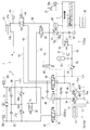
図1は本発明の一実施形態に係る油圧式作業機械の駆動システム1の油圧回路図である。図1に示すように、駆動システム1は、少なくとも1つの油圧アクチュエータ制御回路3,4と、タンク21に貯留された作動油を油圧アクチュエータ制御回路3,4へ供給する駆動装置10と、駆動システム1の動作を制御する制御装置7とを備えている。油圧アクチュエータ制御回路3,4は、作業機械が備える油圧アクチュエータの動作を制御するための油圧回路である。本実施形態に係る駆動システム1には、上部旋回体を旋回駆動する油圧アクチュエータである油圧モータ31の動作を制御するための油圧モータ制御回路3と、ブームを昇降駆動する油圧アクチュエータである油圧シリンダ41の動作を制御するための油圧シリンダ制御回路4との、2つの油圧アクチュエータ制御回路3,4が含まれている。以下、駆動システム1の各構成要素について詳細に説明する。
FIG. 1 is a hydraulic circuit diagram of a drive system 1 for a hydraulic work machine according to an embodiment of the present invention. As shown in FIG. 1, the drive system 1 includes at least one hydraulic actuator control circuit 3, 4, a
[駆動装置10]
まず、駆動装置10について説明する。駆動装置10は、メイン駆動機構10aとして、タンク21に貯えられた作動油を吐出するメインポンプ14,15と、メインポンプ14,15を駆動するエンジン11と、メインポンプ14,15から油圧アクチュエータ制御回路3,4へ作動油を供給する供給ライン30,40とを備えている。本実施形態においては、メインポンプ14,15として第1ポンプ14と第2ポンプ15との2つの油圧ポンプを備えており、第1ポンプ14と接続された第1供給ライン30と第2ポンプ15と接続された第2供給ライン40との2つの供給ライン30,40が設けられている。エンジン11の出力軸12と、メインポンプ14,15の駆動軸16とは、動力伝達機構13を介して接続されている。
[Drive device 10]
First, the
メインポンプ14,15は、例えば斜板式油圧ポンプや斜軸式油圧ポンプなどの可変容量形油圧ポンプである。本実施形態においては、各メインポンプ14,15は斜板式油圧ポンプであって、斜板の傾転角は制御装置7が出力した制御信号により制御される傾転角操作装置14a,15aによって操作される。第1供給ライン30は油圧モータ制御回路3と接続されており、第1ポンプ14によってタンク21に貯留された作動油が油圧モータ制御回路3へ圧送される。また、第2供給ライン40は油圧シリンダ制御回路4と接続されており、第2ポンプ15によってタンク21に貯留された作動油が油圧シリンダ制御回路4へ圧送される。
The main pumps 14 and 15 are variable displacement hydraulic pumps such as a swash plate hydraulic pump and a slant shaft hydraulic pump. In the present embodiment, the
駆動装置10は、更に、回生機構10bとして、油圧アクチュエータ制御回路3,4から排出された作動油で回転駆動されるポンプモータ18と、ポンプモータ18の吐出容量を制御するポンプモータコントローラ73と、ポンプモータ18の出力軸と接続された電動発電機22と、電動発電機22に接続されたインバータ71及び電動発電機コントローラ72と、インバータ71と接続されたキャパシタ(蓄電器の一例)26と、油圧アクチュエータ制御回路3,4から排出された作動油をポンプモータ18へ送る回生ラインと81,82と、モータ動作しているポンプモータ18から排出された作動油を流体エネルギーとして蓄えるアキュムレータ(蓄圧器の一例)51とを備えている。この回生機構10bでは、電動発電機22と結合されたポンプモータ18と、アキュムレータ51とが直列的に接続されて成る電油複合的システムが構築されており、油圧アクチュエータ31,41から排出された作動油の持つエネルギーが電気エネルギー及び流体エネルギー(流体圧力)として効率的に回収され、この回収されたエネルギーが再利用される。
The
ポンプモータ18は、作動油が流れる方向に応じて、モータ動作とポンプ動作とを行うことができる。ポンプモータ18は、少なくとも1つの油圧アクチュエータ制御回路3,4から排出された作動油を受けることによりモータ動作を行い、少なくとも1つの油圧アクチュエータ制御回路3,4に作動油を供給することによりポンプ動作を行う。ポンプモータ18は、例えば斜板式油圧ポンプモータや斜軸式油圧ポンプモータなどの可変容量形の油圧ポンプモータであって、モーター動作時は斜板の傾転角に応じた回転数であり且つ供給される作動油の量に応じた動力を出力する。本実施形態に係るポンプモータ18は斜板式油圧ポンプモータであって、傾転角操作装置18aによって斜板の傾転角が操作される。傾転角操作装置18aは、例えば、ポンプモータコントローラ73が出力した制御信号により制御されるレギュレータなどである。
The
ポンプモータ18と油圧モータ制御回路3とはモータ側回生ライン81で接続されており、ポンプモータ18と油圧シリンダ制御回路4とはシリンダ側回生ライン82で接続されており、油圧アクチュエータ制御回路3,4からの排油が回生ライン81,82を通ってポンプモータ18へ送られる。モータ動作時のポンプモータ18は、油圧アクチュエータ制御回路3,4から送られてきた作動油を排出することで、作動油の流体エネルギーから軸の回転運動(即ち、機械エネルギー)を取り出すことができる。ポンプモータ18の出力軸の回転は、電動発電機22の入力軸へ伝達されて、電動発電機22を回転駆動させる。
The
電動発電機22は、ポンプモータ18の回転出力を受けて電力を得る発電機としての機能と、キャパシタ26から電力の供給を受けて回転運動を出力する電動機としての機能とを有する。電動発電機22と電気的に接続されたインバータ71は、回生コンバータを内蔵したインバータであって、発電機として機能する電動発電機22から電気エネルギーを取り出してキャパシタ26へ蓄える。また、インバータ71は、電動機として機能する電動発電機22へキャパシタ26に蓄えられていた電気エネルギーを供給する。電動発電機22とインバータ71の動作は、電動発電機コントローラ72によって制御されている。
The
モータ動作しているポンプモータ18から排出された作動油は、アキュムレータ51に蓄えられる。アキュムレータ51は、作動油を加圧状態で貯えておく容器であって、作動油の液体エネルギーを蓄えておくことと、蓄えた流体エネルギーを放出することとが可能である。モータ動作しているポンプモータ18の二次側とアキュムレータ51とはブーストライン84で直列的に接続されている。ポンプモータ18を流れて発電に利用された作動油は、ブーストライン84を通じてアキュムレータ51へ流入して貯えられる。
The hydraulic fluid discharged from the
ブーストライン84には、制御装置7の出力信号により制御される開閉弁52が設けられている。開閉弁52は、通常時閉の電磁式切替弁であって、通常時はブーストライン84の作動油の流通が制限されている。開閉弁52が開放されると、ブーストライン84の作動油の流通が許容され、アキュムレータ51に作動油のエネルギーを蓄えるか、アキュムレータ51からエネルギーを放出することができる状態となる。
The
ブーストライン84のポンプモータ18と開閉弁52との間には、逆止弁53を備えたサクションライン54が接続されている。また、ブーストライン84の開閉弁52とアキュムレータ51との間には、所定圧以上で開放される保護バルブ(安全弁)55を備えたドレンライン56が接続されている。更に、ブーストライン84の開閉弁52とアキュムレータ51との間には、ブーストライン84及びアキュムレータ51内の作動油の圧力を計測する圧力計57が設けられている。圧力計57は、例えば、作動油の圧力を電気量に変換する圧力変換器であって、圧力計57で計測されたアキュムレータ51の作動油の圧力を表す信号は、制御装置7へ出力される。
A suction line 54 including a
ポンプモータ18は、アシストライン83によって第2供給ライン40と接続されている。なお、本実施形態においては、モータ側回生ライン81、シリンダ側回生ライン82、及びアシストライン83の一部が共用されているが、それぞれ独立した油路として形成されていてもよい。アシストライン83には、制御装置7の出力信号により制御される回生アシスト切替弁85が設けられている。回生アシスト切替弁85は、アシストライン83が閉止された回生モードと、アシストライン83が開放されたアシストモードとに切り替えることができる。回生アシスト切替弁85がアシストモードのときは、アシストライン83と第2供給ライン40とが連通されて、アキュムレータ51に貯えられた作動油が、電動発電機22により駆動されてポンプ動作を行うポンプモータ18、及び、アシストライン83を通じて第2供給ライン40へ供給される。
The
[油圧モータ制御回路3]
次に、油圧モータ制御回路3について説明する。油圧モータ制御回路3は、第1ポンプ14から吐出された作動油によって駆動される上部構造体旋回用の油圧モータ31と、油圧モータ31の吸入ポートと排出ポートとに接続された油路33,34と、旋回コントロール弁32とを備えている。各油路33,34には、油路33,34の作動油の圧力を検出する圧力計35a,35bが設けられている。旋回コントロール弁32は、油路33,34と第1供給ライン30(30a)との間に設けられ、これらの間の作動油の流通を制御している。なお、油圧モータ31の吸入ポートと排出ポートとは回転方向によって逆になる。
[Hydraulic motor control circuit 3]
Next, the hydraulic motor control circuit 3 will be described. The hydraulic motor control circuit 3 includes an upper structure turning
旋回コントロール弁32は、スプール式の3位置切替弁である。この旋回コントロール弁32のスプールの位置を切り替えることで、油圧モータ31の出力軸を正回転、停止、又は逆回転させることができる。旋回コントロール弁32は、スプールが中立位置にあるときに第1供給ライン30と油路(33又は34)との間の作動油の流通を制限する。また、旋回コントロール弁32は、スプールが中立位置から紙面右又は左に移動しているときに、第1供給ライン30と油路(33又は34)との間の作動油の流通を許容する。なお、スプールが紙面右側にあるときは第1供給ライン30と油路34とが接続され、スプールが紙面左側にあるときは第1供給ライン30と油路33とが接続される。
The turning
油圧モータ制御回路3の2つの油路33,34の間には、通常使用時の圧力を超えた場合にタンク21へ作動油を逃すように作動するリリーフ弁36a,36bと、油路33,34内での油循環時に油量が減るとタンク21から油を吸引するチェック弁37a,37bとが設けられている。リリーフ弁36a,36bとチェック弁37a,37bとは、油圧モータ31の正回転及び逆回転時に作動油が流れる方向が異なるので、油路33,34の各々において適切な向きに設けられている。
Between the two
油圧モータ制御回路3の2つの油路33,34の間には、更に、油圧モータ31の正回転及び逆回転時に応じて戻し側の油路(33又は34)を選択的にモータ側回生ライン81と接続する旋回方向切替弁38が設けられている。更に、モータ側回生ライン81には、油圧アクチュエータ制御回路3からの排油を利用した回生と非回生とを切り替える旋回回生切替弁39が設けられている。旋回方向切替弁38及び旋回回生切替弁39は、制御装置7の出力信号により制御されている。
Between the two
[油圧シリンダ制御回路4]
続いて、油圧シリンダ制御回路4について説明する。油圧シリンダ制御回路4は、第1ポンプ14及び第2ポンプ15から吐出される作動油によって駆動されるブーム昇降用の油圧シリンダ41と、油圧シリンダ41のボトムポート41aと接続された第1油路43と、油圧シリンダ41のヘッドポート41bと接続された第2油路44と、第1油路43及び第2油路44と第2供給ライン40との間に設けられたブームコントロール弁42とを備えている。
[Hydraulic cylinder control circuit 4]
Next, the hydraulic cylinder control circuit 4 will be described. The hydraulic cylinder control circuit 4 includes a boom
ブームコントロール弁42は、スプール式の3位置切替弁である。このブームコントロール弁42のスプールの位置を切り替えることで、第1油路43及び第2油路44のうち一方が第2供給ライン40と接続され他方がタンク21と接続されるように、油圧シリンダ制御回路4の作動油の流れ方向が切り換えられ、油圧シリンダ41に内挿されたピストンを当該ピストンの進行方向から見て前進、停止、又は後退させることができる。ブームコントロール弁42は、スプールが中立位置にあるときに、第2供給ライン40と油路43,44との間の作動油の流通を制限する。また、ブームコントロール弁42は、スプールが中立位置から紙面右側に移動した位置にあるとき(ブーム上げ時)に、第2供給ライン40と第1油路43とを接続し、タンク21と第2油路44とを接続する。また、ブームコントロール弁42は、スプールが中立位置から紙面左側に移動した位置にあるとき(ブーム下げ時)に、第2供給ライン40と第2油路44とを接続し、タンク21と第1油路43とを接続する。
The
油圧シリンダ制御回路4は、更に、第1油路43と接続された補助油路47と、第1供給ライン30と補助油路47との間に設けられた切替弁48とを備えている。切替弁48は、通常閉止されており、ブーム上げ時に開放される。これにより、ブーム上げ時には、第1供給ライン30と補助油路47とが連通されて、第1ポンプ14から吐出された作動油が第1供給ライン30及び補助油路47を通じて第1油路43へ供給され、より速やかにブームの上昇が行われる。なお、旋回コントロール弁32、ブームコントロール弁42、及び切替弁48は、リモートコントローラ25により操作されるコントロールバルブユニット20を構成している。
The hydraulic cylinder control circuit 4 further includes an auxiliary oil passage 47 connected to the
油圧シリンダ制御回路4の第1油路43には、制御装置7が出力した制御信号により制御されるブーム回生切替弁45が設けられている。ブーム回生切替弁45は、ブーム下げ時に、油圧シリンダ41から排出された作動油をブームコントロール弁42を通じてタンク21へ流す非回生モードと、油圧シリンダ41から排出された作動油をシリンダ側回生ライン82へ流す回生モードとに、第1油路43の流路を切り替えることができる。ブーム回生切替弁45は、通常時は非回生モードになっている。第1油路43の油圧シリンダ41とブーム回生切替弁45との間には、第1油路43の作動油の圧力を検出する圧力計46が設けられている。圧力計46は、例えば、作動油の圧力を電気量に変換する圧力変換器であって、圧力計46で計測された第2油路44の作動油の圧力を表す信号は、制御装置7へ出力される。
The
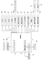
[制御装置7]
続いて、制御装置7について説明する。図2は、駆動システム1の制御構成を示すブロック図である。図2に示すように、制御装置7には、油圧モータ制御回路3の油路33,34に設けられた圧力計35a,35b、油圧シリンダ制御回路4の第1油路43に設けられた圧力計46、ブーストライン84に設けられた圧力計57、及び、リモートコントローラ25の操作圧力を電気量に変換する圧力変換器25aが電気的に接続されており、これらの計器で検出された圧力信号が入力される。また、制御装置7には、旋回方向切替弁38、旋回回生切替弁39、ブーム回生切替弁45、開閉弁52、及び、回生アシスト切替弁85の各弁が電気的に接続されている。制御装置7は、これら各弁の動作を制御する制御信号を出力するように構成されている。更に、制御装置7には、第1ポンプ14の傾転角操作装置14a、第2ポンプ15の傾転角操作装置15a、及び、ポンプモータ18の傾転角操作装置18aが電気的に接続されている。制御装置7は、これらの傾転角操作装置を制御するように構成されている。
[Control device 7]
Next, the
制御装置7は、いわゆるコンピュータであって、CPU、ROM、RAM、I/F、I/O等を有している(いずれも図示せず)。ROMには、CPUが実行するプログラム、各種固定データ等が記憶されている。CPUが実行するプログラムは、フレキシブルディスク、CD−ROM、メモリカード等の各種記憶媒体に保存されており、これらの記憶媒体からROMにインストールされる。RAMには、プログラム実行時に必要なデータが一時的に記憶される。I/Fは、外部装置とのデータ送受信を行う。I/Oは、各種センサの検出信号や各種電磁弁などの操作信号の入力/出力を行う。制御装置7では、ROMに記憶されたプログラム等のソフトウェアとCPU等のハードウェアとが協働することにより、以下に説明する制御装置7の各機能を実現する処理を行うように構成されている。なお、制御装置7は単一のCPUにより各処理を実行してもよいし、複数のCPU或いはCPUと特定の処理回路の組み合わせにより各処理を実行してもよい。また、制御装置7は、前述のインバータ71、電動発電機コントローラ72、及びポンプモータコントローラ73を含んで構成されているが、これらのうち少なくとも1つが制御装置7から独立した制御装置として構成されていてもよい。
The
[駆動システム1の動作]
ここで、上記構成の駆動システム1の動作のうち、特に、回生動作及び力行動作について説明する。なお、特に明示しないが、以下で説明する駆動システム1の動作は制御装置7によって制御されている。
[Operation of Drive System 1]
Here, among the operations of the drive system 1 configured as described above, the regenerative operation and the power running operation will be described in particular. Although not clearly indicated, the operation of the drive system 1 described below is controlled by the
(旋回制動時の回生動作)
駆動システム1は、上部旋回体の旋回制動時に上部旋回体の運動エネルギー(及び慣性エネルギー)を流体エネルギー(流体圧力)としてアキュムレータ51に回収して蓄えるとともに、電気エネルギーとしてキャパシタ26に回収して蓄える。
(Regenerative operation during turning braking)
The drive system 1 collects and stores the kinetic energy (and inertia energy) of the upper swing body as fluid energy (fluid pressure) in the
旋回制動時の駆動システム1では、旋回回生切替弁39が回生モードに切り替えられ、開閉弁52が開放され、インバータ71が発電モードに切り替えられる。制御装置7は、リモートコントローラ25へ入力された操作と、各圧力計で計測された作動油圧力とに基づいて、これらの切り替えを行う。また、旋回角度センサを備える場合は、制御装置7はこの旋回角度センサからの角度信号を利用して回生モードと発電モードとの切り替えを行ってもよい。上部旋回体の旋回制動時に油圧モータ31から油路34へ流出した作動油(又は、油圧モータ31から油路33へ出した作動油)は、旋回方向切替弁38からモータ側回生ライン81を通じてポンプモータ18へ流入する。ポンプモータ18へ流入した作動油は、ポンプモータ18と接続された電動発電機22を回転させ、この回転エネルギーがインバータ71によって電気エネルギーとして取り出されてキャパシタ26に蓄えられる。そして、ポンプモータ18から排出された作動油は、アキュムレータ51に貯えられる。
In the drive system 1 at the time of turning braking, the turning
(ブーム下げ時の回生動作)
駆動システム1は、ブーム下げ時にブームの運動エネルギー(及び位置エネルギー)を流体エネルギー(流体圧力)としてアキュムレータ51に回収して蓄えるとともに、電気エネルギーとしてキャパシタ26に回収して蓄える。
(Regenerative operation when the boom is lowered)
The drive system 1 collects and stores the kinetic energy (and potential energy) of the boom as fluid energy (fluid pressure) in the
ブーム下げ時の駆動システム1では、ブーム回生切替弁45が回生モードに切り替えられ、開閉弁52が開放され、インバータ71が発電モードに切り替えられる。制御装置7は、リモートコントローラ25へ入力された操作と、各圧力計で計測された作動油圧力とに基づいて、これらの切り替えを行う。また、油圧シリンダのストロークを検出するセンサを備える場合は、制御装置7はこのセンサからの信号を利用して回生モードと発電モードとの切り替えを行ってもよい。ブーム下げ時に油圧シリンダ41から第1油路43へ流出した作動油は、ブーム回生切替弁45及びシリンダ側回生ライン82を通じてポンプモータ18へ流入する。ポンプモータ18へ流入した作動油は、ポンプモータ18と接続された電動発電機22を回転させ、この回転エネルギーがインバータ71によって電気エネルギーとして取り出されてキャパシタ26に蓄えられる。そして、ポンプモータ18から排出された作動油は、アキュムレータ51に貯えられる。
In the drive system 1 when the boom is lowered, the boom
上記の回生動作(ブーム下げ時の回生動作及び旋回制動時の回生動作)では、アキュムレータ51に作動油を流体エネルギーとして蓄えることと、電動発電機22で発電した電気エネルギーをキャパシタ26に蓄えることとが同時並行して行われている。但し、これらのうち一方が先に行われ他方が後で行われてもよい。例えば、上部旋回体の旋回制動を開始したとき又はブームの降下を開始したときに、開閉弁52を解放するとともに旋回回生切替弁39又はブーム回生切替弁45を回生モードに切り替えて、電動発電機22で発電を行わずに、アキュムレータ51に作動油を貯えることだけを行ってもよい。この場合、圧力計57で計測されたアキュムレータ51の圧力が所定圧力を超えると、開閉弁52が閉止されるととともに電動発電機22で発電が行われ、発電された電気エネルギーがキャパシタ26に蓄えられる。
In the above regenerative operation (regenerative operation when the boom is lowered and regenerative operation when turning braking), the hydraulic oil is stored in the
上記の回生動作では、油圧アクチュエータ31,41から排出された作動油のエネルギーが、電気エネルギーとしてキャパシタ26に、流体エネルギーとしてアキュムレータ51に、それぞれ回収されて蓄えられる。このようにポンプモータ18で回収できなかった作動油のエネルギーがアキュムレータ51で蓄えられるので、エネルギーロスを低減することができる。また、駆動システム1は、キャパシタ26とアキュムレータ51のいずれか一方を備える場合と比較して、より多くのエネルギーを回収することが可能となる。よって、従来油圧アクチュエータから排出されたのちタンクに廃棄されていたエネルギーの回収効率を高めることができる。
In the regenerative operation described above, the energy of the hydraulic oil discharged from the
また、モータ動作するポンプモータ18の二次側(即ち、作動油の流れの下流側)にアキュムレータ51が設けられているので、上記の回生動作では、ポンプモータ18の一次側圧力と二次側圧力との差圧を小さくすることが可能となる。つまり、ポンプモータ18に掛かる圧力差(ポンプモータ18の一次側圧力と二次側圧力との差圧)は、油圧アクチュエータ制御回路3,4の負荷で発生する圧力からアキュムレータ51の圧力を減じたものとなる。通常、アキュムレータ51の圧力はタンク21の圧力よりも大きい。そのため、ポンプモータ18から排出された作動油がタンク21へ送られる場合と比較して、アキュムレータ51の圧力分だけ、ポンプモータ18の一次側圧力と二次側圧力との差圧を小さくすることができる。ポンプモータ18の一次側圧力と二次側圧力との差圧が小さくなれば、ポンプモータ18を回転させるために使用される流体エネルギーが減少するので、電動発電機22及びキャパシタ26といった電気機器の小型化が可能となる。
In addition, since the
また、ポンプモータ18がモータ動作している間の、油圧アクチュエータ31,41の動作を制御するために、制御装置7によって電動発電機22の回転数(即ち、ポンプモータ18の回転数)が制御される。アキュムレータ51に貯えられる作動油の増減に伴ってアキュムレータ51の圧力が変化し、ポンプモータ18に掛かる差圧が変化するが、上記のように電動発電機22の回転数が制御されることによって、ポンプモータ18の作動油の流量が制御される。これにより、油圧アクチュエータ制御回路3,4から排出される作動油の流量、ひいては、上部旋回体の制動速度やブームの降下速度が制御され、例えば、これらの速度を一定速度に保持することが可能となる。このようなポンプモータ18の流量制御によれば、バルブなどの絞りを流路に設けて作動油の流量を制御する場合と比較して、エネルギー損失を低減することができる。
Further, in order to control the operation of the
更に、上記の回生動作では、ポンプモータ18の一次側圧力と二次側圧力との差圧が電動発電機22の発電能力に応じた所定値以下となるように、制御装置7によってポンプモータ18の吐出容量が制御される。具体例を挙げると、ポンプモータ18に掛かる差圧が、電動発電機22の発電能力に応じた許容値よりも大きい場合は、許容値よりも小さな値となるように、ポンプモータ18の斜板の傾転角が変更される。ポンプモータ18の一次側圧力と二次側圧力の差圧は、油圧アクチュエータ制御回路3,4から排出されてくる作動油の圧力や、アキュムレータ51に貯えられている作動油の圧力によって変化することがあるが、この差圧が電動発電機22の発電能力に応じた所定値以下に維持されることによって電動発電機22の過負荷を防ぐことができる。また、ポンプモータ18の一次側圧力と二次側圧力の差圧を電動発電機22の発電能力に合わせることができるので、油圧アクチュエータ制御回路3,4から排出される作動油の量や圧力に関係なく、所望の発電能力の電動発電機22を駆動システム1に採用することができる。
Further, in the regenerative operation described above, the
(ブーム上げ時の力行動作)
駆動システム1は、ブーム上げ時に、アキュムレータ51に蓄えられている流体エネルギーとキャパシタ26に蓄えられている電気エネルギーとで、エンジン11のアシストを行う。
(Power running when the boom is raised)
When the boom is raised, the drive system 1 assists the engine 11 with the fluid energy stored in the
ブーム上げ時には、回生アシスト切替弁85がアシストモードに切り替えられ、開閉弁52が開放され、インバータ71が電動発電機22へ電気エネルギーを供給する電動機モードに切り替えられる。制御装置7は、リモートコントローラ25へ入力された操作と、各圧力計で計測された作動油圧力とに基づいて、これらの切り替えを行う。ブーム上げ時には、電動機として機能する電動発電機22が、キャパシタ26に蓄えられた電気エネルギーを用いてモータとして動作することによって、ポンプモータ18にポンプ動作を行わせる。そして、ポンプ動作を行うポンプモータ18によって、アキュムレータ51に貯えられた作動油が、ブーストライン84、ポンプモータ18、及びアシストライン83を通じて、第2供給ライン40へ圧送される。
When the boom is raised, the regeneration assist switching
上記の力行動作では、アキュムレータ51に貯えられた常圧よりも高圧の作動油が、ポンプ動作しているポンプモータ18で更に昇圧されてアシストライン83へ吐出される。アキュムレータ51に貯えられた作動油はそのままでは高圧ラインへ送ることはできないが、ポンプモータ18で所望の圧力まで昇圧されるので、第2供給ライン40といった高圧ライン、又は、直接に油圧シリンダ41へ送ることが可能である。また、アキュムレータ51に貯えられた作動油は常圧よりも高圧であることから、アキュムレータ51に貯えられた作動油を所望の圧力に昇圧するためのエネルギーは、タンク21の作動油を昇圧させる場合と比較して、アキュムレータ51の圧力の分だけ少ない。
In the power running operation described above, the hydraulic oil having a pressure higher than the normal pressure stored in the
第2供給ライン40では、アキュムレータ51から送られた作動油の分だけ、メインポンプ15の吐出量を低減することができる。このようにして、アキュムレータ51に蓄えられた流体エネルギーと、キャパシタ26に蓄えられた電気エネルギーによって、エンジン11の動力がアシストされるので、省エネに寄与することができる。
In the
上記の力行動作において、アキュムレータ51に蓄えられた作動油の量の変動によりポンプ動作しているポンプモータ18の一次側圧力が変動する。例えば、アキュムレータ51に蓄えられた作動油が減少すると、ポンプモータ18の一次側圧力が減少する。そこで、力行動作においては、ポンプモータ18からアシストライン83へ吐出される作動油の油圧が所定値となるように、電動発電機22の回転トルクが制御される。つまり、ポンプモータ18の一次側圧力の変動が、電動発電機22の調整された回転トルクにより相殺される。これにより、ポンプモータ18からアシストライン83へ吐出されて第2供給ライン40へ送られる作動油の圧力を一定に保持することができ、安定したエンジンアシストを行うことができる。
In the power running operation described above, the primary pressure of the
上記の力行動作において、ポンプ動作時のポンプモータ18の吐出容量は、モータ動作時のポンプモータ18の吐出容量と比較して小さくなるように制御される。傾転角が0のときに吐出量が最小であり、傾転角が大きくなるに従って吐出量が増えるように構成された斜板式可変容量形ポンプモータの場合、ポンプ動作時のポンプモータ18の斜板の傾転角は、モータ動作時のポンプモータ18の斜板の傾転角と比較して小さくなるように制御される。そして、ポンプモータ18の斜板の傾転角を変化させることにより、ポンプモータ18での作動油の昇圧の程度が調整される。上記のようにポンプモータ18の傾転角が制御されることにより、ポンプ動作時ではポンプモータ18による作動油の昇圧の程度を高めることができ、モータ動作時ではポンプモータ18に掛かる負荷を小さくすることとを両立させることができる。ポンプモータ18に掛かる負荷が小さくなれば、電動発電機22に要求される発電能力(出力)を小さくすることができる。つまり、ポンプ動作時のポンプモータ18の吐出容量を、第2供給ライン40で要求される作動油の圧力に応じて制御するとともに、モータ動作時のポンプモータ18の吐出容量を電動発電機22の発電能力に応じて制御することで、電動発電機22を発電能力を大きくすることなく、高圧油を生成することができる。
In the above power running operation, the discharge capacity of the
上記のようなポンプモータ18の吐出容量の制御の具体的な数値例を、以下で説明する。例えば、ブーム下げ時の回生動作において、油圧シリンダ41のヘッド側の圧力が10〜12MPaであり、アキュムレータ51の圧力が5MPaであると仮定すれば、ポンプモータ18の一次側圧力と二次側圧力の差圧は5〜7MPaである。ポンプモータ18として4000rpmの高速回転油圧モータを採用し、ブーム下げ時の作動油の流量を400〜450L/minとすれば、ポンプモータ18は容積112cc/revで作動油を受け入れることができる。このように、回転数4000rpmにて、ポンプモータ18の容積が112cc/rev、差圧が7MPa、効率が0.9であれば、ポンプモータ18から取り出せる軸出力は47kWとなる。ポンプモータ18に接続される電動発電機22の効率を0.9とすると、電動発電機22から取り出せる軸出力は42kWとなる。この発電量は、比較的小容量のキャパシタ26で全て回収することが可能である。
Specific numerical examples of the control of the discharge capacity of the
一方、ブーム上げ時の力行動作において、ポンプ動作時のポンプモータ18の斜板の傾転角をモータ動作時の斜板の傾転角の1/2として、アキュムレータ51のブーストされた高圧油を、ポンプモータ18からアシストライン83へ吐出する。ポンプモータ18の斜板の傾転角が1/2となっているので、およそ10MPa以上の昇圧が可能である。従って、ポンプモータ18からアシストライン83へ吐出される作動油は、アキュムレータ51のブーストされた圧力と合わせて、20MPa以上に昇圧することができる。このように、アキュムレータ51に蓄えられている作動油が、第2供給ライン40などの高圧ラインで使用できる程度の高圧に昇圧することが可能である。
On the other hand, in the power running operation when the boom is raised, the boosted high-pressure oil of the
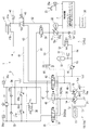
以上に本発明の好適な実施の形態を説明したが、上記の構成は例えば以下のように変更することができる。例えば、キャパシタ26又はアキュムレータ51の容量に余裕があるときは、油圧アクチュエータ31,41の動作が停止している間に、第2供給ライン40からアシストライン83を経由してポンプモータ18へ作動油を送って、この作動油のエネルギーをキャパシタ26及びアキュムレータ51の少なくとも一方に蓄えるように駆動システム1が構成されていてもよい。この場合、図3の変形例1に係る油圧回路図に示すように、回生アシスト切替弁85を、アシストライン83が開放されているときに双方向流通可能な弁とすることができる。つまり、アシストライン83を通じて第2供給ライン40からポンプモータ18へ作動油を送ることと、アシストライン83を通じてポンプモータ18から第2供給ライン40へ作動油を送ることとが可能となっている。このように、油圧アクチュエータ31,41の動作が停止している間にメインポンプ14,15から吐出した作動油のエネルギーをキャパシタ26及びアキュムレータ51の少なくとも一方に蓄えることによれば、エンジン11の稼働を効率の良い状態で継続することが可能となり、燃費の向上を図ることができる。
The preferred embodiment of the present invention has been described above, but the above configuration can be modified as follows, for example. For example, when the capacity of the
また、例えば、上述の油圧作業機械の駆動システム1では、油圧モータ31と油圧シリンダ41の2つの油圧アクチュエータを制御するために2つの油圧アクチュエータ制御回路3,4を備えているが、駆動システム1が備える油圧アクチュエータ制御回路の数はこれに限定されず、1つ又は2つ以上の複数とすることができる。そして、駆動システム1が備えるメインポンプ14,15、供給ライン30,40、回生ライン81,82などの数は、油圧アクチュエータ制御回路の数に応じて増減することができる。
Further, for example, the drive system 1 of the hydraulic working machine described above includes two hydraulic actuator control circuits 3 and 4 for controlling the two hydraulic actuators of the
1 駆動システム
3 油圧モータ制御回路(油圧アクチュエータ制御回路)
4 油圧シリンダ制御回路(油圧アクチュエータ制御回路)
7 制御装置
10 駆動装置
11 エンジン
14 第1ポンプ(メインポンプ)
14a 傾転角操作装置
15 第2ポンプ(メインポンプ)
15a 傾転角操作装置
18 ポンプモータ
18a 傾転角操作装置
20 コントロールバルブユニット
21 タンク
22 電動発電機
25 リモートコントローラ
26 キャパシタ
30 第1供給ライン(供給ライン)
31 油圧モータ(油圧アクチュエータ)
32 旋回コントロール弁
38 旋回方向切替弁
39 旋回回生切替弁
40 第2供給ライン(供給ライン)
41 油圧シリンダ(油圧アクチュエータ)
42 ブームコントロール弁
45 ブーム回生切替弁
48 切替弁
51 アキュムレータ
52 開閉弁
71 インバータ
72 電動発電機コントローラ
73 ポンプモータコントローラ
81 モータ側回生ライン(回生ライン)
82 シリンダ側回生ライン(回生ライン)
83 アシストライン
84 ブーストライン
85 回生アシスト切替弁
1 Drive System 3 Hydraulic Motor Control Circuit (Hydraulic Actuator Control Circuit)
4 Hydraulic cylinder control circuit (hydraulic actuator control circuit)
7
14a Tilt
15a Tilt
31 Hydraulic motor (hydraulic actuator)
32
41 Hydraulic cylinder (hydraulic actuator)
42
82 Cylinder side regenerative line (regenerative line)
83
Claims (7)
タンクに貯えられた作動油を吐出するポンプと、
前記ポンプを駆動するエンジンと、
前記ポンプから前記少なくとも1つの油圧アクチュエータ制御回路へ作動油を供給する供給ラインと、
前記少なくとも1つの油圧アクチュエータ制御回路から排出された作動油を受けることによりモータ動作を行い、前記少なくとも1つの油圧アクチュエータ制御回路に作動油を供給することによりポンプ動作を行うポンプモータと、
前記ポンプモータの出力軸と接続された電動発電機と、
前記ポンプモータのモータ動作時に発電機として機能し、前記ポンプモータのポンプ動作時に電動機として機能するように、前記電動発電機の動作を制御する電動発電機コントローラと、
前記電動発電機で発電した電気エネルギーを蓄える蓄電器と、
前記少なくとも1つの油圧アクチュエータ制御回路から排出された作動油を前記ポンプモータへ送る回生ラインと、
前記回生ラインから前記ポンプモータへ流入し前記ポンプモータから排出された作動油を回収して流体エネルギーとして蓄える蓄圧器とを、備えている
油圧式作業機械の駆動システム。 At least one hydraulic actuator control circuit for controlling the operation of the hydraulic actuator of the hydraulic work machine;
A pump that discharges hydraulic oil stored in the tank;
An engine for driving the pump;
A supply line for supplying hydraulic fluid from the pump to the at least one hydraulic actuator control circuit;
A pump motor that performs a motor operation by receiving hydraulic oil discharged from the at least one hydraulic actuator control circuit, and performs a pump operation by supplying hydraulic oil to the at least one hydraulic actuator control circuit;
A motor generator connected to the output shaft of the pump motor;
A motor generator controller that controls the operation of the motor generator so as to function as a generator during motor operation of the pump motor and to function as a motor during pump operation of the pump motor;
A battery for storing electrical energy generated by the motor generator;
A regenerative line for sending hydraulic oil discharged from the at least one hydraulic actuator control circuit to the pump motor;
A drive system for a hydraulic work machine, comprising: a pressure accumulator that collects hydraulic oil that flows into the pump motor from the regeneration line and is discharged from the pump motor and stores it as fluid energy.
前記ポンプモータの吐出容量を制御するポンプモータコントローラを、更に備えている、請求項1〜4のいずれか一項に記載の油圧式作業機械の駆動システム。 The pump motor is a variable displacement hydraulic pump motor;
The drive system for a hydraulic work machine according to any one of claims 1 to 4, further comprising a pump motor controller that controls a discharge capacity of the pump motor.
Priority Applications (1)
| Application Number | Priority Date | Filing Date | Title |
|---|---|---|---|
| JP2014213027A JP2016080098A (en) | 2014-10-17 | 2014-10-17 | Driving system of hydraulic working machine |
Applications Claiming Priority (1)
| Application Number | Priority Date | Filing Date | Title |
|---|---|---|---|
| JP2014213027A JP2016080098A (en) | 2014-10-17 | 2014-10-17 | Driving system of hydraulic working machine |
Publications (1)
| Publication Number | Publication Date |
|---|---|
| JP2016080098A true JP2016080098A (en) | 2016-05-16 |
Family
ID=55958089
Family Applications (1)
| Application Number | Title | Priority Date | Filing Date |
|---|---|---|---|
| JP2014213027A Pending JP2016080098A (en) | 2014-10-17 | 2014-10-17 | Driving system of hydraulic working machine |
Country Status (1)
| Country | Link |
|---|---|
| JP (1) | JP2016080098A (en) |
Cited By (6)
| Publication number | Priority date | Publication date | Assignee | Title |
|---|---|---|---|---|
| CN108194437A (en) * | 2018-02-28 | 2018-06-22 | 福建工程学院 | A kind of potential energy recycling and the pump hydraulic energy conserving system of electric machine speed regulation |
| CN108678048A (en) * | 2018-05-25 | 2018-10-19 | 太原理工大学 | A kind of energy storage hoisting system of liquid electricity combination drive |
| DE112016006744T5 (en) | 2016-04-13 | 2018-12-27 | Autonetworks Technologies, Ltd. | Connector end wire rod and connector containing the same |
| CN113175450A (en) * | 2021-05-14 | 2021-07-27 | 华侨大学 | Closed electro-hydraulic control system for mechanical arm of asymmetric cylinder |
| CN113983039A (en) * | 2021-11-18 | 2022-01-28 | 中冶赛迪工程技术股份有限公司 | Hydraulic lifting mechanism cluster control system |
| KR102406200B1 (en) * | 2020-12-22 | 2022-06-08 | 울산대학교 산학협력단 | Continuously Variable Powertrain With Integrated Hydraulic Flywheel To Saver Energy In The Boom System |
Citations (6)
| Publication number | Priority date | Publication date | Assignee | Title |
|---|---|---|---|---|
| JP2004028233A (en) * | 2002-06-26 | 2004-01-29 | Komatsu Ltd | Hydraulic energy recovery system |
| JP2007010006A (en) * | 2005-06-29 | 2007-01-18 | Shin Caterpillar Mitsubishi Ltd | Hybrid system for work machines |
| JP2008202343A (en) * | 2007-02-21 | 2008-09-04 | Hitachi Constr Mach Co Ltd | Hydraulic drive unit for construction machinery |
| JP2013148141A (en) * | 2012-01-18 | 2013-08-01 | Sumitomo Heavy Ind Ltd | Energy regenerating device for construction machines |
| JP2013160251A (en) * | 2012-02-01 | 2013-08-19 | Hitachi Constr Mach Co Ltd | Power regeneration device for work machine |
| JP2013170597A (en) * | 2012-02-17 | 2013-09-02 | Hitachi Constr Mach Co Ltd | Construction machine |
-
2014
- 2014-10-17 JP JP2014213027A patent/JP2016080098A/en active Pending
Patent Citations (6)
| Publication number | Priority date | Publication date | Assignee | Title |
|---|---|---|---|---|
| JP2004028233A (en) * | 2002-06-26 | 2004-01-29 | Komatsu Ltd | Hydraulic energy recovery system |
| JP2007010006A (en) * | 2005-06-29 | 2007-01-18 | Shin Caterpillar Mitsubishi Ltd | Hybrid system for work machines |
| JP2008202343A (en) * | 2007-02-21 | 2008-09-04 | Hitachi Constr Mach Co Ltd | Hydraulic drive unit for construction machinery |
| JP2013148141A (en) * | 2012-01-18 | 2013-08-01 | Sumitomo Heavy Ind Ltd | Energy regenerating device for construction machines |
| JP2013160251A (en) * | 2012-02-01 | 2013-08-19 | Hitachi Constr Mach Co Ltd | Power regeneration device for work machine |
| JP2013170597A (en) * | 2012-02-17 | 2013-09-02 | Hitachi Constr Mach Co Ltd | Construction machine |
Cited By (8)
| Publication number | Priority date | Publication date | Assignee | Title |
|---|---|---|---|---|
| DE112016006744T5 (en) | 2016-04-13 | 2018-12-27 | Autonetworks Technologies, Ltd. | Connector end wire rod and connector containing the same |
| CN108194437A (en) * | 2018-02-28 | 2018-06-22 | 福建工程学院 | A kind of potential energy recycling and the pump hydraulic energy conserving system of electric machine speed regulation |
| CN108194437B (en) * | 2018-02-28 | 2023-10-24 | 福建工程学院 | Double-pump hydraulic energy-saving system for potential energy recovery and motor speed regulation |
| CN108678048A (en) * | 2018-05-25 | 2018-10-19 | 太原理工大学 | A kind of energy storage hoisting system of liquid electricity combination drive |
| CN108678048B (en) * | 2018-05-25 | 2021-01-29 | 太原理工大学 | A hydraulic-electric hybrid-driven energy storage lifting system |
| KR102406200B1 (en) * | 2020-12-22 | 2022-06-08 | 울산대학교 산학협력단 | Continuously Variable Powertrain With Integrated Hydraulic Flywheel To Saver Energy In The Boom System |
| CN113175450A (en) * | 2021-05-14 | 2021-07-27 | 华侨大学 | Closed electro-hydraulic control system for mechanical arm of asymmetric cylinder |
| CN113983039A (en) * | 2021-11-18 | 2022-01-28 | 中冶赛迪工程技术股份有限公司 | Hydraulic lifting mechanism cluster control system |
Similar Documents
| Publication | Publication Date | Title |
|---|---|---|
| CN104105888B (en) | Engineering machinery | |
| CN103765019B (en) | The fluid pressure drive device of engineering machinery | |
| KR101652112B1 (en) | Hybrid Excavator Boom Actuator System and its Control Method | |
| CN103703258B (en) | Engineering machinery | |
| US9037356B2 (en) | Control device for hybrid construction machine | |
| US9618014B2 (en) | Implement system having hydraulic start assist | |
| US20140123633A1 (en) | Energy recovery method and system | |
| CN105492782B (en) | The pressure oil energy recycle device of Work machine | |
| JP2016080098A (en) | Driving system of hydraulic working machine | |
| KR20160079814A (en) | Hydraulic pressure circuit and working machine | |
| CN108894274B (en) | Excavator gyration energy recuperation and system of recycling | |
| JP5873456B2 (en) | Work machine drive control system, work machine including the same, and drive control method thereof | |
| US9995018B2 (en) | Control system of hybrid construction machine | |
| WO2009119705A1 (en) | Controller of hybrid construction machine | |
| WO2012050028A1 (en) | Construction machine having rotary element | |
| CN104011400A (en) | Hydraulic closed circuit drive device | |
| KR20160079815A (en) | Hydraulic pressure circuit and working machine | |
| JP2009250361A (en) | Circuit for regenerating hydraulic cylinder operating pressure | |
| EP3037589A1 (en) | Construction machine | |
| EP2444555A1 (en) | Hydraulic control device for construction machine | |
| US7401464B2 (en) | Energy regeneration system for machines | |
| CN115398065B (en) | Hydraulic system and method for controlling hydraulic system of work machine | |
| CN107076182A (en) | The control system of hybrid construction machine | |
| JP2012092546A (en) | Hybrid hydraulic excavator | |
| JP2006124145A (en) | Hydraulic device for battery type industrial vehicle |
Legal Events
| Date | Code | Title | Description |
|---|---|---|---|
| A621 | Written request for application examination |
Free format text: JAPANESE INTERMEDIATE CODE: A621 Effective date: 20170228 |
|
| A977 | Report on retrieval |
Free format text: JAPANESE INTERMEDIATE CODE: A971007 Effective date: 20171221 |
|
| A131 | Notification of reasons for refusal |
Free format text: JAPANESE INTERMEDIATE CODE: A131 Effective date: 20171226 |
|
| A02 | Decision of refusal |
Free format text: JAPANESE INTERMEDIATE CODE: A02 Effective date: 20180626 |