JP2016077360A - Assistance device - Google Patents
Assistance device Download PDFInfo
- Publication number
- JP2016077360A JP2016077360A JP2014209328A JP2014209328A JP2016077360A JP 2016077360 A JP2016077360 A JP 2016077360A JP 2014209328 A JP2014209328 A JP 2014209328A JP 2014209328 A JP2014209328 A JP 2014209328A JP 2016077360 A JP2016077360 A JP 2016077360A
- Authority
- JP
- Japan
- Prior art keywords
- person
- assisted
- handle
- assistance device
- moving mechanism
- Prior art date
- Legal status (The legal status is an assumption and is not a legal conclusion. Google has not performed a legal analysis and makes no representation as to the accuracy of the status listed.)
- Pending
Links
Images


Abstract
Description
本開示は、被介助者の着座から起立までの一連の動作を介助するための介助装置に関する。 The present disclosure relates to an assistance device for assisting a series of operations from sitting to standing of a person being assisted.
一般にトイレ室には、トイレの使用者が把持するための手摺りが設けられているが、高齢者や身体障害者などの中には手摺りだけでは一人で便座に座ったり立ち上がったりするのが難しい場合があり、このような場合には介助者が必要になる。
しかしながら、狭いトイレ室内において着座から起立までの一連の動作を介助することは、介助者にとって大変な労力を要する作業である。また、被介助者にとっても、プライバシーに関するデリケートな問題を含むため、出来る限り介助者なしに一人の力でトイレを利用したいとの要望がある。
In general, handrails are provided in the toilet room for gripping by the toilet user. However, some elderly people and physically handicapped people can sit or stand on the toilet seat alone with the handrail alone. It can be difficult, and in such cases, an assistant is required.
However, assisting a series of operations from sitting to standing in a narrow toilet room is a work that requires a great deal of labor for the assistant. There is also a demand for the care recipient to use the toilet with the help of one person as much as possible without the helper as much as possible because it involves a sensitive issue regarding privacy.
そこで、当該分野における従来技術として、例えば特許文献1に開示されているトイレ用介助装置がある。この特許文献1のトイレ用介助装置は、トイレに設置されるトイレ用介助装置であって、便器の左右側方に配設される左右のガイドレールと、該左右のガイドレールにガイドされて便器の左右を前後方向に移動する左右の可動ベースと、該左右の可動ベース間に上下動自在に支架され、左右の可動ベースと一体的に前後移動する手摺り部材と、便器の左右側方に配され、手摺り部材と同期して前後移動する左右の足載せ部材と、を有する。そして、手摺り部材および左右の足載せ部材が前後移動することで、トイレの使用者は、手摺り部材に体が支持された、且つ、左右の足載せ部材に足を乗せた安定状態で、便器の手前位置と所定の着座位置との間を移動することができるようになっている。また、手摺り部材を着座位置で上下動させることにより、手摺り部材に体が支持された安定状態で用を足すことができるようになっている。
Therefore, as a conventional technique in the field, there is a toilet assistance device disclosed in
しかしながら、特許文献1のトイレ介助装置にあっては、専用の便器構造を要するなど、汎用性に欠けるとの問題があった。また、トイレの使用者が着座または起立する際に手摺り部材は単純に上下方向に移動するだけであり、着座動作および起立動作における理想的な姿勢(非特許文献1を参照)を考慮したものにはなっておらず、トイレの使用者が着座または起立する際の補助としては不十分なものであった。
However, the toilet assistance device of
本発明の少なくとも一つの実施形態は、このような従来技術の状況の基になされた発明であって、その目的とするところは、シンプルな構造で汎用性に優れるとともに、被介助者の着座から起立までの一連の動作において、被介助者にとって最も適した介助を行うことの出来る介助装置を提供することにある。 At least one embodiment of the present invention is an invention based on such a state of the art, and the object is to have a simple structure and excellent versatility, and from the sitting of a person being assisted An object of the present invention is to provide an assistance device that can perform assistance most suitable for the person being assisted in a series of operations up to standing.
(1)本発明の少なくとも一つの実施形態にかかる介助装置は、
被介助者の着座から起立までの一連の動作を介助するための介助装置であって、
前記被介助者を支持可能なハンドルと、
前記ハンドルを上下方向の軸線周りに回転可能に吊り支持するとともに、前記ハンドルを上下方向および前後方向に移動させるための移動機構体と、
前記移動機構体の駆動を制御するためのコントローラと、を備え、
前記コントローラは、
前記被介助者が着座から起立までの一連の動作を行う際に前記ハンドルが描く移動軌跡であって前記被介助者に対応する理想の移動軌跡を認識可能な軌跡認識部と、
前記軌跡認識部が認識する理想の移動軌跡に基づいて、前記移動機構体の駆動を制御可能な駆動制御部と、を含む。
(1) An assistance device according to at least one embodiment of the present invention includes:
An assistance device for assisting a series of operations from sitting to standing of a person being assisted,
A handle capable of supporting the person being assisted;
A suspension mechanism that supports the handle so as to be rotatable around an axis in the vertical direction, and a moving mechanism for moving the handle in the vertical direction and the front-rear direction;
A controller for controlling the driving of the moving mechanism body,
The controller is
A trajectory recognizing unit capable of recognizing an ideal trajectory corresponding to the person being assisted, which is a movement trajectory drawn by the handle when the person being assisted performs a series of operations from sitting to standing;
And a drive control unit capable of controlling the driving of the moving mechanism based on an ideal movement locus recognized by the locus recognition unit.
上記(1)に記載の介助装置によれば、被介助者が着座から起立までの一連の動作を行う際に、被介助者に対応する理想の移動軌跡を描くように、被介助者を支持するハンドルの上下方向および前後方向の移動が制御される。 According to the assistance device described in (1) above, when the person being assisted performs a series of operations from sitting to standing, the person being assisted is drawn so as to draw an ideal movement locus corresponding to the person being assisted. The movement of the steering wheel in the vertical direction and the front-back direction is controlled.
ここで「理想の移動軌跡」とは、被介助者にとって最も身体的な負担の少ないと考えられる移動軌跡であり、本発明者らが検討したところでは、股関節の軌跡が略斜め45度に直線状に延伸し、起立の際における重心の軌跡が下向きの略円弧形状を描くような軌跡である。このような「理想の移動軌跡」は、性別や、身長、体重などの体型によって異なるのは勿論のこと、同じ様な体型の被介助者であっても、各被介助者の癖や筋肉の付き方、負傷箇所の有無やその程度などによっても異なってくる。
そこで、本実施形態では、被介助者に対応する理想の移動軌跡を認識可能な軌跡認識部と、軌跡認識部が認識する理想の移動軌跡に基づいて移動機構体の駆動を制御可能な駆動制御部と、を含むコントローラを備えることにより、被介助者の着座から起立までの一連の動作において、被介助者にとって最も適した介助を行うことが出来るようになっている。
Here, the “ideal movement trajectory” is a movement trajectory that is considered to have the least physical burden on the person being assisted, and the present inventors have investigated that the trajectory of the hip joint is a straight line approximately 45 degrees diagonally. The locus of the center of gravity at the time of standing up is a locus that draws a downward substantially arc shape. Such “ideal movement trajectory” varies depending on the gender, height, weight, and other body types, and even if the person has the same body shape, It depends on how it is attached, whether or not there is an injured part, and its degree.
Therefore, in this embodiment, a trajectory recognition unit capable of recognizing an ideal movement trajectory corresponding to the person being assisted, and a drive control capable of controlling the driving of the moving mechanism based on the ideal movement trajectory recognized by the trajectory recognition unit. By providing a controller including the unit, it is possible to perform assistance most suitable for the person being assisted in a series of operations from sitting to standing of the person being assisted.
また、本実施形態の介助装置は、被介助者を支持可能なハンドルと、ハンドルを吊り支持するとともに、ハンドルを上下方向および前後方向に移動させるための移動機構体とを備える。このように、ハンドルを吊り支持する構造としたことで、トイレ室内の床面上にガイドレールを配設し、手摺り及び足載せ台をガイドレールに沿って移動させるように構成される特許文献1の介助装置などと比べて、シンプルな構造で汎用性に優れる介助装置となっている。
Further, the assistance device of the present embodiment includes a handle that can support the person being assisted, and a moving mechanism body that suspends and supports the handle and moves the handle in the vertical direction and the front-rear direction. In this way, by adopting a structure that supports and supports the handle, the guide rail is arranged on the floor surface in the toilet room, and the handrail and the footrest are configured to move along the guide rail. Compared to the
(2)幾つかの実施形態では、上記(1)に記載の介助装置において、コントローラは、移動機構体の駆動に関する駆動指示信号を受信可能な駆動指示受信部をさらに含む。そして、駆動制御部は、駆動指示信号に基づいて、移動機構体の駆動を進行または停止させるように制御する。 (2) In some embodiments, in the assistance device according to (1) above, the controller further includes a drive instruction receiving unit capable of receiving a drive instruction signal related to driving of the moving mechanism body. And a drive control part controls so that a drive of a moving mechanism body may advance or stop based on a drive instruction | indication signal.
上記(2)に記載の実施形態によれば、移動機構体の駆動に関する駆動指示信号に基づいて移動機構体の駆動が制御される。したがって、例えば、被介助者の操作によって駆動指示信号をコントローラに送信可能に構成することで、被介助者の意志によって移動機構体の駆動を制御することが出来る。 According to the embodiment described in (2) above, the driving of the moving mechanism is controlled based on the drive instruction signal related to the driving of the moving mechanism. Therefore, for example, by configuring the driving instruction signal to be transmitted to the controller by the operation of the person being assisted, the driving of the moving mechanism body can be controlled according to the will of the person being assisted.
(3)幾つかの実施形態では、上記(1)又は(2)に記載の介助装置において、軌跡認識部は、被介助者に対応する理想の移動軌跡を予め記憶する軌跡記憶部と、不特定の被介助者の中から特定の被介助者を認識するための被介助者認識部と、軌跡記憶部が記憶する理想の移動軌跡の中から、被介助者認識部が認識する被介助者に対応した理想の移動軌跡を選定するための軌跡選定部と、からなる。 (3) In some embodiments, in the assistance device according to the above (1) or (2), the locus recognition unit includes a locus storage unit that stores an ideal movement locus corresponding to the person being assisted in advance, A caregiver recognizing unit for recognizing a specific person being assisted from a specific person being assisted, and a person being assisted by the person being recognized by the person being recognized from the ideal movement locus stored in the locus storage unit And a trajectory selection unit for selecting an ideal movement trajectory corresponding to.
上記(3)に記載の実施形態によれば、不特定の被介助者の中から特定の被介助者を認識し、予め記憶している理想の移動軌跡の中から認識した被介助者に対応した理想の移動軌跡を選定する。したがって、不特定の被介助者に対し、各々の被介助者に対応する理想の移動軌跡に基づいて着座から起立までの一連の動作を介助することが出来る。 According to the embodiment described in (3) above, a specific person being assisted is recognized from among unspecified persons, and the person being assisted is recognized from an ideal movement trajectory stored in advance. Select the ideal movement trajectory. Therefore, a series of actions from sitting to standing can be assisted for an unspecified person being assisted based on an ideal movement locus corresponding to each person being assisted.
(4)幾つかの実施形態では、上記(3)に記載の介助装置において、介助装置は、被介助者の動作を検出可能な動作検出センサをさらに備える。 (4) In some embodiments, in the assistance device according to (3) above, the assistance device further includes an operation detection sensor capable of detecting the operation of the person being assisted.
上記(4)に記載の実施形態によれば、動作検出センサで検出した被介助者の動作に関する情報を、被介助者の着座から起立までの一連の動作を介助するために利用することが出来る。 According to the embodiment described in the above (4), the information on the movement of the person being assisted detected by the movement detection sensor can be used for assisting a series of movements from sitting to standing of the person being assisted. .
(5)幾つかの実施形態では、上記(4)に記載の介助装置において、コントローラは、動作検出センサで検出される被介助者の動作に基づいて、軌跡記憶部に記憶される被介助者に対応する理想の移動軌跡を修正する軌跡修正部をさらに含む。 (5) In some embodiments, in the assistance device according to (4) above, the controller is configured to store the person being assisted stored in the trajectory storage unit based on the movement of the person being assisted detected by the motion detection sensor. And a trajectory correction unit for correcting an ideal movement trajectory corresponding to.
上記(5)に記載の実施形態によれば、動作検出センサで検出した被介助者の動作に関する情報に基づいて、軌跡記憶部に記憶される被介助者に対応する理想の移動軌跡を修正する学習機能を介助装置に付加させることが出来る。 According to the embodiment described in (5) above, the ideal movement trajectory corresponding to the person being assisted stored in the trajectory storage unit is corrected based on the information related to the person being assisted detected by the motion detection sensor. A learning function can be added to the assistance device.
(6)幾つかの実施形態では、上記(3)〜(5)の何れかに記載の介助装置において、介助装置は、被介助者の発する音声を認識可能な音声認識センサをさらに備える。 (6) In some embodiments, in the assistance device according to any one of (3) to (5), the assistance device further includes a voice recognition sensor capable of recognizing a voice uttered by the person being assisted.
上記(6)に記載の実施形態によれば、被介助者の発する音声を、被介助者の着座から起立までの一連の動作を介助するために利用することが出来る。 According to the embodiment described in the above (6), the voice uttered by the person being assisted can be used to assist a series of operations from sitting to standing of the person being assisted.
(7)幾つかの実施形態では、上記(6)に記載の介助装置において、被介助者認識部は、音声認識センサが認識する被介助者の発する音声に基づいて、不特定の被介助者から特定の被介助者を認識するように構成されている。 (7) In some embodiments, in the assistance device described in (6) above, the person being assisted recognizer is an unspecified person being assisted based on the voice uttered by the person being assisted recognized by the voice recognition sensor. It is configured to recognize a specific person being assisted.
上記(7)に記載の実施形態によれば、被介助者の発する音声によって、不特定の中から被介助者から特定の被介助者を認識することが出来る。したがって、例えば、予め記している理想の移動軌跡の中から特定の被介助者に対応した理想の移動軌跡を選定する際において、不特定の被介助者の中から特定の被介助者を容易に認識することが出来る。 According to the embodiment described in (7) above, the specific person being assisted can be recognized from the person being assisted by the voice uttered by the person being assisted. Therefore, for example, when selecting an ideal movement trajectory corresponding to a specific person to be attended from among the ideal movement trajectories described in advance, a specific person to be attended can be easily selected from among unspecified persons to be attended. Can be recognized.
(8)幾つかの実施形態では、上記(2)に記載の介助装置において、介助装置は、ハンドルに支持されている被介助者の身体の向きを転向可能なターンテーブルをさらに備える。そして駆動制御部は、駆動指示信号に基づいてターンテーブルの回転駆動を進行または停止させるように制御する。 (8) In some embodiments, in the assistance device according to (2) above, the assistance device further includes a turntable capable of turning the direction of the person being assisted by the handle. Then, the drive control unit performs control so as to advance or stop the rotational drive of the turntable based on the drive instruction signal.
上記(8)に記載の実施形態によれば、ターンテーブルによって被介助者の身体の向きを転向させることが出来る。したがって、例えばトイレ室などの狭い場所などで被介助者の身体の向きを転向する場合において、被介助者の身体の向きを容易に転向させることが出来る。また、このターンテーブルの回転駆動は、上述した駆動指示信号に基づいて制御される。したがって、例えば、被介助者の操作によって駆動指示信号をコントローラに送信可能に構成することで、被介助者の意志によってターンテーブルの回転駆動を制御することが出来る。 According to the embodiment described in (8) above, the orientation of the person being assisted can be turned by the turntable. Therefore, for example, when turning the direction of the person being assisted in a narrow place such as a toilet room, the direction of the person being assisted can be easily changed. Further, the rotation drive of the turntable is controlled based on the drive instruction signal described above. Therefore, for example, by configuring the driving instruction signal to be transmitted to the controller by the operation of the person being assisted, the rotational drive of the turntable can be controlled according to the will of the person being assisted.
(9)幾つかの実施形態では、上記(8)に記載の介助装置において、介助装置は、駆動指示信号を発信可能な駆動指示装置をさらに備える。
そして駆動制御部は、被介助者の身体の向きを規定角度だけ転向させた後に、被介助者の着座から起立までの一連の動作を介助するように、駆動指示装置のプッシュボタンがプッシュされている時には、移動機構体の駆動を進行させるか又はターンテーブルの回転駆動を進行させ、プッシュボタンがプッシュされていない時には、移動機構体の駆動を停止させるか又はターンテーブルの回転駆動を停止させるように構成される。
(9) In some embodiments, in the assistance device according to (8), the assistance device further includes a drive instruction device capable of transmitting a drive instruction signal.
The drive control unit then pushes the push button of the drive instruction device so as to assist a series of operations from sitting to standing of the person being assisted after turning the person's body by a specified angle. When the push button is not pushed, the drive of the moving mechanism is stopped or the rotation drive of the turntable is stopped. Configured.
上記(9)に記載の実施形態によれば、駆動指示信号を発信可能な駆動指示装置をさらに備える。したがって、例えば被介助者が駆動指示装置を操作することで、被介助者の身体の向きの転向および着座から起立までの一連の動作を介助するように、被介助者の意志によってターンテーブル又は移動機構体の駆動を制御することが出来る。
また、駆動指示装置のプッシュボタンをプッシュしている間だけ移動機構体の駆動又はターンテーブルの回転駆動が進行するように構成される。したがって、プッシュボタンを離すと移動機構体の駆動又はターンテーブルの回転駆動が停止するため、被介助者の意に反して移動機構体の駆動又はターンテーブルの回転駆動が進行する虞が少なく、安全性に優れている。
According to the embodiment described in (9) above, it further includes a drive instruction device capable of transmitting a drive instruction signal. Therefore, for example, when the person being assisted operates the drive instruction device, a turntable or movement is made depending on the will of the person being assisted so as to assist a series of movements from the sitting direction to the standing position of the person being assisted. The drive of the mechanism can be controlled.
Further, the driving of the moving mechanism or the rotational driving of the turntable is performed only while the push button of the drive instruction device is pushed. Therefore, when the push button is released, the drive of the moving mechanism or the rotational drive of the turntable stops, so there is little possibility that the drive of the moving mechanism or the rotational drive of the turntable will proceed against the intention of the person being assisted. Excellent in properties.
(10)幾つかの実施形態では、上記(1)〜(9)の何れかに記載の介助装置において、ハンドルは、上下方向に沿って延在する一対の把持部と、一対の把持部の先端部に夫々形成される湾曲状の一対のフック部と、一対の把持部の基端部を夫々連結する水平方向に延在する連結部とを含む。そして、連結部が、移動機構体によって吊り支持されている。 (10) In some embodiments, in the assistance device according to any one of (1) to (9), the handle includes a pair of gripping portions extending in the vertical direction, and a pair of gripping portions. It includes a pair of curved hook portions respectively formed at the distal end portions and a connecting portion extending in the horizontal direction for connecting the base end portions of the pair of gripping portions. And the connection part is suspended and supported by the moving mechanism body.
上記(10)に記載の実施形態によれば、把持部とフック部と連結部とからなるシンプルなハンドル構造とすることが出来る。また、被介助者は、一対の把持部を両手で夫々把持しながら一対のフック部を両脇で夫々挟み込むような体勢でハンドルに支持される。したがって、このような実施形態のハンドルによれば、被介助者を安定した体勢で支持することが出来る。 According to the embodiment described in (10) above, a simple handle structure including a gripping portion, a hook portion, and a connecting portion can be provided. Further, the person being assisted is supported by the handle in such a posture that the pair of hook portions are sandwiched between the both sides while the pair of grip portions are gripped with both hands. Therefore, according to the handle of such an embodiment, the person being assisted can be supported in a stable posture.
(11)幾つかの実施形態では、上記(10)に記載の介助装置において、ハンドルは、湾曲状のフック部の先端が下向きに傾くように前後方向に傾倒可能に構成される。 (11) In some embodiments, in the assistance device described in (10) above, the handle is configured to be tiltable in the front-rear direction so that the tip of the curved hook portion tilts downward.
上記(11)に記載の実施形態によれば、被介助者が一対のフック部を両脇で夫々挟み込むことを容易に行うことが出来る。 According to the embodiment described in (11) above, the person being assisted can easily sandwich the pair of hook portions on both sides.
(12)幾つかの実施形態では、上記(1)〜(11)の何れかに記載の介助装置において、移動機構体は、ハンドルを前後方向に移動させるための前後用アクチュエータと、ハンドルを上下方向に移動させるための昇降用アクチュエータとを含む。前後用アクチュエータおよび前記昇降用アクチュエータの各々は、筐体内に収容されているボールネジと、ボールネジを回転可能なサーボモータと、ボールネジの回転に伴い、ボールネジの延在方向に沿って移動可能なスライダとを有する単軸アクチュエータからなる。そして、駆動制御部は、サーボモータの回転を制御することで移動機構体の駆動を制御するように構成されている。 (12) In some embodiments, in the assistance device according to any one of (1) to (11), the moving mechanism body includes a front / rear actuator for moving the handle in the front / rear direction, and a handle up / down. And an elevating actuator for moving in the direction. Each of the front / rear actuator and the lifting / lowering actuator includes a ball screw accommodated in a housing, a servo motor capable of rotating the ball screw, and a slider movable along the extending direction of the ball screw as the ball screw rotates. It consists of a single axis actuator having. The drive control unit is configured to control the driving of the moving mechanism body by controlling the rotation of the servo motor.
上記(12)に記載の実施形態によれば、汎用部品である単軸アクチュエータを使用して移動機構体を構成することが出来るため、製造性、コスト性に優れている。 According to the embodiment described in (12) above, since the moving mechanism body can be configured using a single-axis actuator that is a general-purpose component, it is excellent in manufacturability and cost.
(13)幾つかの実施形態では、上記(12)に記載の介助装置において、前後用アクチュエータは、前後用アクチュエータのスライダに固定される、水平方向に延在する水平部および水平部の両端から下方に向かって延在する一対のアーム部を有する下向きU字状に形成された前後スライダを有する。一対のアーム部の夫々には、2つの昇降用アクチュエータがアーム部の夫々に固定される。そして、2つの昇降用アクチュエータは、2つの昇降用アクチュエータのスライダに夫々固定される単一の昇降スライダを有しており、該昇降スライダにハンドルが連結されている。 (13) In some embodiments, in the assistance device according to (12), the front / rear actuator is fixed to a slider of the front / rear actuator, and extends horizontally from both ends of the horizontal portion. It has a front and rear slider formed in a downward U-shape having a pair of arm portions extending downward. Two lifting / lowering actuators are fixed to each of the arm portions of each of the pair of arm portions. The two lifting actuators have a single lifting slider fixed to the sliders of the two lifting actuators, and a handle is connected to the lifting slider.
上記(13)に記載の実施形態によれば、1つの前後用アクチュエータと、2つの昇降用アクチュエータからなるシンプルな構造によって、ハンドルを前後方向および上下方向の2軸に移動させることが出来る。 According to the embodiment described in (13) above, the handle can be moved in the front-rear direction and the vertical direction by a simple structure including one front-rear actuator and two elevating actuators.
(14)幾つかの実施形態では、上記(1)〜(13)の何れかに記載の介助装置において、上記介助装置が、便座が配置されるトイレ室に設けられるトイレ用介助装置からなる。 (14) In some embodiments, in the assistance device according to any one of (1) to (13), the assistance device includes a toilet assistance device provided in a toilet room in which a toilet seat is disposed.
このように、上述した被介助者の着座から起立までの一連の動作を介助するための介助装置は、便座が配置されるトイレ室に設けられるトイレ用介助装置として好適に用いることが出来る。 As described above, the assistance device for assisting the series of operations from sitting to standing of the person being assisted can be suitably used as a toilet assistance device provided in a toilet room in which the toilet seat is disposed.
(15)幾つかの実施形態では、上記(14)に記載の解除装置において、上記コントローラは、介助者が前記トイレ室から退室したことを認識可能な退室認識部をさらに含む。そして、上記駆動制御部は、介助者がトイレ室から退室したことを退室認識部が認識すると、ハンドルの回転位置が所定の初期状態となるように、ハンドルを軸線周りに回転させるように構成される。 (15) In some embodiments, in the release device according to the above (14), the controller further includes a leaving recognition unit capable of recognizing that an assistant has left the toilet room. The drive control unit is configured to rotate the handle around the axis so that the rotation position of the handle is in a predetermined initial state when the exit recognition unit recognizes that the assistant has left the toilet room. The
上記(15)に記載の実施形態によれば、介助者がトイレ室から退室したことを認識すると、ハンドルの回転位置が初期状態となるようにハンドルが自動的に回転する。よって、次の利用の際にハンドルを初期状態に戻す必要がないため、利便性に優れている。 According to the embodiment described in (15) above, when the assistant recognizes that he has left the toilet room, the handle automatically rotates so that the rotational position of the handle is in the initial state. Therefore, it is not necessary to return the handle to the initial state at the next use, which is convenient.
本発明の少なくとも一つの実施形態によれば、シンプルな構造で汎用性に優れるとともに、被介助者の着座から起立までの一連の動作において、被介助者にとって最も適した介助を行うことの出来る介助装置を提供することが出来る。 According to at least one embodiment of the present invention, a simple structure and excellent versatility, and assistance that can provide assistance most suitable for the person being assisted in a series of operations from sitting to standing of the person being assisted. A device can be provided.
以下、添付図面を参照して本発明の幾つかの実施形態について説明する。ただし、実施形態として記載されている又は図面に示されている構成部品の寸法、材質、形状、その相対的配置等は、本発明の範囲をこれに限定する趣旨ではなく、単なる説明例にすぎない。
例えば、「ある方向に」、「ある方向に沿って」、「平行」、「直交」、「中心」、「同心」或いは「同軸」等の相対的或いは絶対的な配置を表す表現は、厳密にそのような配置を表すのみならず、公差、若しくは、同じ機能が得られる程度の角度や距離をもって相対的に変位している状態も表すものとする。
例えば、「同一」、「等しい」及び「均質」等の物事が等しい状態であることを表す表現は、厳密に等しい状態を表すのみならず、公差、若しくは、同じ機能が得られる程度の差が存在している状態も表すものとする。
例えば、四角形状や円筒形状等の形状を表す表現は、幾何学的に厳密な意味での四角形状や円筒形状等の形状を表すのみならず、同じ効果が得られる範囲で、凹凸部や面取り部等を含む形状も表すものとする。
一方、一の構成要素を「備える」、「具える」、「具備する」、「含む」、又は、「有する」という表現は、他の構成要素の存在を除外する排他的な表現ではない。
Hereinafter, some embodiments of the present invention will be described with reference to the accompanying drawings. However, the dimensions, materials, shapes, relative arrangements, etc. of the components described in the embodiments or shown in the drawings are not intended to limit the scope of the present invention, but are merely illustrative examples. Absent.
For example, expressions expressing relative or absolute arrangements such as “in a certain direction”, “along a certain direction”, “parallel”, “orthogonal”, “center”, “concentric” or “coaxial” are strictly In addition to such an arrangement, it is also possible to represent a state of relative displacement with an angle or a distance such that tolerance or the same function can be obtained.
For example, an expression indicating that things such as “identical”, “equal”, and “homogeneous” are in an equal state not only represents an exactly equal state, but also has a tolerance or a difference that can provide the same function. It also represents the existing state.
For example, expressions representing shapes such as quadrangular shapes and cylindrical shapes represent not only geometrically strict shapes such as quadrangular shapes and cylindrical shapes, but also irregularities and chamfers as long as the same effects can be obtained. A shape including a part or the like is also expressed.
On the other hand, the expressions “comprising”, “comprising”, “comprising”, “including”, or “having” one constituent element are not exclusive expressions for excluding the existence of the other constituent elements.
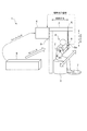
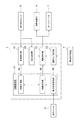
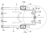
図1は、本発明の一実施形態にかかる介助装置の全体構成を示した全体構成図である。図2は、本発明の一実施形態にかかる介助装置のシステム構成を示したブロック図である。
本発明の一実施形態にかかる介助装置1は、被介助者Pの着座から起立までの一連の動作を介助するための装置であって、例えば被介助者Pがトイレ室の便器5に起立した状態から着座する動作、及び着座した状態から起立する動作を介助するための装置である。以下の実施形態では、介助装置1が、便座が配置されるトイレ室に設けられるトイレ用介助装置である場合を例にして説明する。
FIG. 1 is an overall configuration diagram showing an overall configuration of an assistance device according to an embodiment of the present invention. FIG. 2 is a block diagram showing a system configuration of the assistance device according to the embodiment of the present invention.
The
介助装置1は、図1に示すように、被介助者Pを支持可能なハンドル2と、ハンドル2を上下方向の軸線X周りに回転可能に吊り支持するとともに、ハンドル2を上下方向および前後方向に移動させるための移動機構体3と、移動機構体3の駆動を制御するためのコントローラ4とを備える。
As shown in FIG. 1, the
コントローラ4は、中央処理装置(CPU)、ランダムアクセスメモリ(RAM)、リードオンリメモリ(ROM)、およびI/Oインターフェイスなどからなるマイクロコンピュータで構成されている。
コントローラ4は、図2に示すように、被介助者Pが着座から起立までの一連の動作を行う際にハンドル2が描く移動軌跡であって被介助者Pに対応する理想の移動軌跡を認識可能な軌跡認識部41と、軌跡認識部41が認識する理想の移動軌跡に基づいて、移動機構体3の駆動を制御可能な駆動制御部42とを含む。移動機構体3は、軌跡認識部41が認識する理想の移動軌跡に基づいて、ハンドル2を上下方向および前後方向に移動させる。
The controller 4 includes a microcomputer including a central processing unit (CPU), a random access memory (RAM), a read only memory (ROM), an I / O interface, and the like.
As shown in FIG. 2, the controller 4 recognizes an ideal movement locus corresponding to the person being assisted by the
このような介助装置1によれば、被介助者Pが着座から起立までの一連の動作を行う際に、被介助者Pに対応する理想の移動軌跡を描くように、被介助者Pを支持するハンドル2の上下方向および前後方向の移動が制御される。
According to such an
ここで「理想の移動軌跡」とは、被介助者にとって最も身体的な負担の少ないと考えられる移動軌跡である。本発明者らが検討したところでは、図1の矢印(a)に示すように股関節の軌跡が略斜め45度に直線状に延伸し、図1の矢印(b)に示すように起立の際における重心の軌跡が下向きの略円弧形状を描くような軌跡である。後述する図4中の符号T1は、着座する際の理想の移動軌跡、符号T2は起立する際の理想の移動軌跡の一例を示している。移動機構体3は、着座する際は軌跡T1を描くように、また、起立する際は軌跡T2を描くように、ハンドル2を上下方向および前後方向に移動させる。
Here, the “ideal movement trajectory” is a movement trajectory that is considered to have the least physical burden on the person being assisted. As a result of the study by the present inventors, the locus of the hip joint extends linearly at an angle of approximately 45 degrees as shown by the arrow (a) in FIG. 1, and when standing up as shown by the arrow (b) in FIG. The trajectory of the center of gravity in FIG. Reference numeral T1 in FIG. 4 described later indicates an example of an ideal movement locus when sitting, and reference numeral T2 indicates an example of an ideal movement locus when standing. The moving
このような「理想の移動軌跡」は、性別や、身長、体重などの体型によって異なるのは勿論のこと、同じ様な体型の被介助者であっても、各被介助者の癖や筋肉の付き方、負傷箇所の有無やその程度などによっても異なってくる。 Such “ideal movement trajectory” varies depending on the gender, height, weight, and other body types, and even if the person has the same body shape, It depends on how it is attached, whether or not there is an injured part, and its degree.
そこで、本実施形態では、被介助者Pに対応する理想の移動軌跡を認識可能な軌跡認識部41と、軌跡認識部41が認識する理想の移動軌跡に基づいて移動機構体3の駆動を制御可能な駆動制御部42とを含むコントローラ4を備えることにより、被介助者Pの着座から起立までの一連の動作において、被介助者Pにとって最も適した介助を行うことが出来るようになっている。
Therefore, in the present embodiment, the
また、本実施形態の介助装置1は、被介助者Pを支持可能なハンドル2と、ハンドル2を吊り支持するとともに、ハンドル2を上下方向および前後方向に移動させるための移動機構体3とを備える。このように、ハンドル2を吊り支持する構造としたことで、トイレ室内の床面上にガイドレールを配設し、手摺り及び足載せ台をガイドレールに沿って移動させるように構成される従来の特許文献1の介助装置などと比べて、シンプルな構造で汎用性に優れる介助装置となっている。
Further, the
幾つかの実施形態では、図2に示したように、コントローラは、移動機構体3の駆動に関する駆動指示信号を受信可能な駆動指示受信部43をさらに含む。そして、駆動制御部42は、駆動指示信号に基づいて、移動機構体3の駆動を進行または停止させるように制御する。
In some embodiments, as illustrated in FIG. 2, the controller further includes a drive
ここで駆動指示信号は、後述するように、被介助者Pがハンドル2などに固定されている駆動指示装置8を操作することでコントローラ4に送信されるように構成してもよい。また、被介助者Pの特定の動作を動作検出センサ6が認識することで、動作検出センサ6からコントローラ4に駆動信号が送信されるように構成してもよい。また、被介助者Pの発する特定の音声を音声認識センサ9が認識することで、音声認識センサ9からコントローラ4に駆動指示信号が送信されるように構成してもよい。また、被介助者Pを介助する介助者がリモコンなどを操作することで、リモコンからコントローラ4に駆動指示信号が送信されるように構成してもよい。
Here, the driving instruction signal may be configured to be transmitted to the controller 4 by operating the driving instruction device 8 fixed by the
このような実施形態によれば、移動機構体3の駆動に関する駆動指示信号に基づいて移動機構体3の駆動が制御される。したがって、例えば、被介助者Pの操作によって駆動指示信号をコントローラ4に送信可能に構成することで、被介助者Pの意志によって移動機構体の駆動を制御することが出来る。また、被介助者Pを介助する介助者がリモコンなどを操作することで駆動指示信号をコントローラ4に送信可能に構成することで、介助者の適切な監視の下で移動機構体3の駆動を制御することが出来る。
According to such an embodiment, the driving of the moving
幾つかの実施形態では、図2に示したように、上述した軌跡認識部41は、被介助者Pに対応する理想の移動軌跡を予め記憶する軌跡記憶部44と、不特定の被介助者の中から特定の被介助者Pを認識するための被介助者認識部45と、軌跡記憶部44が記憶する理想の移動軌跡の中から、被介助者認識部45が認識する被介助者Pに対応した理想の移動軌跡を選定するための軌跡選定部46とからなる。
In some embodiments, as shown in FIG. 2, the
軌跡記憶部44は、複数の被介助者に対応する複数の理想の移動軌跡を被介助者と関連づけて記憶している。被介助者認識部45は、被介助者を識別するための識別情報を記憶しており、被介助者に関する識別情報が被介助者認識部45に送信されると、送信された識別情報と記憶されている識別情報とを照合することで、不特定の被介助者の中から特定の被介助者Pを認識する。そして軌跡選定部46は、特定の被介助者Pに対応する理想の移動軌跡を軌跡記憶部44に記憶されている複数の理想の移動軌跡の中から選定する。
The
ここで識別情報としては、不特定の被介助者の中から特定の被介助者Pを認識することが出来る情報であれば何でもよく、例えば後述する音声認識センサ9が認識することの出来る音声であってもよい。また、別途設けられる指紋認識センサが認識可能な指紋、顔認識センサが認識可能な顔の形状であってもよい。
Here, as the identification information, any information can be used as long as it can recognize a specific person P among unspecified persons, for example, a voice that can be recognized by a
このような実施形態によれば、不特定の被介助者の中から特定の被介助者Pを認識し、予め記憶している理想の移動軌跡の中から認識した被介助者Pに対応した理想の移動軌跡を選定する。したがって、不特定の被介助者に対し、各々の被介助者に対応する理想の移動軌跡に基づいて着座から起立までの一連の動作を介助することが出来る。このため、例えば、介護施設に設置されるトイレ室など、不特定の被介助者が利用するトイレ室などに好適に用いることができる。 According to such an embodiment, the specific person P is recognized from among unspecified persons, and the ideal corresponding to the person P recognized from the pre-stored ideal movement trajectory. Select the movement trajectory. Therefore, a series of actions from sitting to standing can be assisted for an unspecified person being assisted based on an ideal movement locus corresponding to each person being assisted. For this reason, for example, it can use suitably for the toilet room etc. which an unspecified care recipient uses, such as the toilet room installed in a care facility.
幾つかの実施形態では、図1に示したように、介助装置1は、被介助者Pの動作を検出可能な動作検出センサ6をさらに備える。
このような動作検出センサ6としては、例えばkinect(登録商標)などの従来周知の動作検出センサを用いることが出来る。この種の動作検出センサは、カメラと深度センサを有しており、人間の関節などの動きを奥行きを有する画像データとして把握することが可能となっている。また、動作検出センサ6の設置位置は、被介助者Pの着座から起立までの一連の動作を検出可能な位置であればよく、特に限定されない。動作検出センサ6で検出された被介助者Pの動作に関する情報は、無線または有線を介してコントローラ4に送信(フィードバック)される。
In some embodiments, as illustrated in FIG. 1, the
As such a
このような実施形態によれば、動作検出センサ6で検出した被介助者の関節の動きに関する情報を、被介助者Pの着座から起立までの一連の動作を介助するために利用することが出来る。
According to such an embodiment, the information about the movement of the person being assisted detected by the
幾つかの実施形態では、図2に示したように、コントローラ4は、動作検出センサ6で検出される被介助者Pの動作に基づいて、軌跡記憶部44に記憶される被介助者Pに対応する理想の移動軌跡を修正する軌跡修正部47をさらに含む。
In some embodiments, as illustrated in FIG. 2, the controller 4 may determine whether the person being assisted P stored in the
図示した実施形態では、動作検出センサ6で検出される被介助者Pの動作に関する情報が軌跡修正部47に送信されるように構成されている。そして、軌跡修正部47では、検出された動作に不自然なところがあれば、本来のあるべき理想の移動軌跡との間にズレがあると判断する。そして、被介助者Pの動作から不自然さが消えるように、記憶している理想の移動軌跡を修正する。
In the illustrated embodiment, information related to the movement of the person being assisted P detected by the
具体的には、動作検出センサ6は、被介助者Pの各関節、体幹角度、股関節、膝関節、足関節、腕の位置、頭の位置などを検出可能である。この際、被介助者Pの立ち位置での床反力も測定可能に構成されているとよい。また一方で、既存の資料などから、頭、体幹、大腿、下腿といった人の身体の各部位の重心位置及び体重比率を算出し、これらに基づいて予め人体モデルを予め生成しておく。また、人体モデルにおける静力学的な力の釣り合いを計算しておく。そして、これらの人体モデルを含むデータをコントローラ4に記憶しておく。そして、これら動作検出センサ6が検出する被介助者Pの動作と、コントローラ4に記憶されている人体モデルを含むデータとから、その立ち方、座り方だと各関節への負担がどれぐらい大きいのかを評価することが出来る。また、床反力を測定することで、実際に介助装置1がどれぐらいの力を補助しているのかも算出することが出来る。そして、これらの結果に基づいて、本来のあるべき理想の移動軌跡との間にどれぐらいズレがあるかを評価し、記憶している理想の移動軌跡を修正することが出来る。
Specifically, the
また例えば、動作検出センサ6による被介助者Pの動作の検出と併せて、被介助者Pの発する音声や顔の表情などを検出し、被介助者Pの発する音声や顔の表情などから本来あるべき理想の移動軌跡との間にズレがあるか否かを判断するように構成してもよい。
Further, for example, together with the detection of the movement of the person being assisted P by the
このような実施形態によれば、動作検出センサ6で検出した被介助者Pの動作に基づいて、軌跡記憶部44に記憶される被介助者Pに対応する理想の移動軌跡を修正する学習機能を介助装置1に付加させることが出来る。また、介助装置1がこのような学習機能を有していれば、被介助者Pの毎日の身体の変化に合わせて記憶している理想の移動軌跡も徐々に修正されることとなる。よって、例えばリハビリ途中の被介助者Pなどに対し、望ましい立ち方や座り方などを指導するに際して、好適に用いられる。
According to such an embodiment, a learning function for correcting an ideal movement locus corresponding to the person being assisted P stored in the
幾つかの実施形態では、図1に示すように、介助装置1は、被介助者Pの発する音声を認識可能な音声認識センサ9をさらに備える。
In some embodiments, as illustrated in FIG. 1, the
このような実施形態によれば、上述したように、不特定の被介助者の中から特定の被介助者Pを認識する場合や、軌跡記憶部44に記憶される被介助者Pに対応する理想の移動軌跡を修正する場合などにおいて、被介助者Pの発する音声を被介助者Pの着座から起立までの一連の動作を介助するために利用することが出来る。
According to such an embodiment, as described above, it corresponds to the case of recognizing a specific person being assisted from unspecified persons being assisted or the person being assisted P stored in the
幾つかの実施形態では、上述したように、被介助者認識部45は、音声認識センサ9が認識する被介助者Pの発する音声に基づいて、不特定の被介助者から特定の被介助者Pを認識するように構成されている。
In some embodiments, as described above, the person being assisted by the person being assisted 45 recognizes a specific person being assisted by an unspecified person to be assisted based on the sound uttered by the person assisted by the
このような実施形態によれば、被介助者Pの発する音声によって、不特定の中から被介助者から特定の被介助者Pを認識することが出来る。したがって、例えば、予め記している理想の移動軌跡の中から特定の被介助者Pに対応した理想の移動軌跡を選定する際において、不特定の被介助者の中から特定の被介助者Pを容易に認識することが出来る。 According to such an embodiment, the specific person to be assisted P can be recognized from the person to be assisted from unspecified by the sound uttered by the person to be assisted P. Therefore, for example, when selecting an ideal movement trajectory corresponding to a specific person being assisted from among the ideal movement loci described in advance, a specific person to be assisted P is selected from among unspecified persons being assisted. It can be easily recognized.
幾つかの実施形態では、図1に示したように、介助装置1は、ハンドル2に支持されている被介助者Pの身体の向きを転向可能なターンテーブル7をさらに備える。そして駆動制御部42は、駆動指示信号に基づいてターンテーブル7の回転駆動を進行または停止させるように制御する。
In some embodiments, as illustrated in FIG. 1, the
このような実施形態によれば、ターンテーブル7によって被介助者Pの身体の向きを転向させることが出来る。したがって、例えばトイレ室などの狭い場所などで被介助者Pの身体の向きを転向する場合において、被介助者Pの身体の向きを容易に転向させることが出来る。また、このターンテーブル7の回転駆動は、上述した駆動指示信号に基づいて制御される。したがって、例えば、被介助者Pの操作によって駆動指示信号をコントローラ4に送信可能に構成することで、被介助者Pの意志によってターンテーブル7の回転駆動を制御することが出来る。
According to such an embodiment, the body direction of the person being assisted P can be turned by the
幾つかの実施形態では、図1に示したように、介助装置1は、駆動指示信号を発信可能な駆動指示装置8をさらに備える。
そして駆動制御部42は、被介助者Pの身体の向きを規定角度だけ転向させた後に、被介助者Pの着座から起立までの一連の動作を介助するように、駆動指示装置8のプッシュボタン8aがプッシュされている時には、移動機構体3の駆動を進行させるか又はターンテーブル7の回転駆動を進行させ、プッシュボタン8aがプッシュされていない時には、移動機構体3の駆動を停止させるか又はターンテーブル7の回転駆動を停止させるように構成される。
In some embodiments, as illustrated in FIG. 1, the
The
駆動指示装置8は、例えばハンドル2などの被介助者Pが操作し易い部分において、介助装置1に一体的に取り付けられている。図示した実施形態では、駆動指示装置8は、ハンドル2の被介助者Pが把持する部分に固定されている。ターンテーブル7の回転角度は、トイレ室の構造(便器の向きとトイレ室のドアの位置関係)によって規定され、例えばトイレ室のドアの正面に便器が配置されている場合は、180度回転するように規定される。
The drive instructing device 8 is integrally attached to the assisting
このような実施形態によれば、駆動指示信号を発信可能な駆動指示装置8をさらに備える。したがって、例えば被介助者Pが駆動指示装置8を操作することで、被介助者Pの身体の向きの転向および着座から起立までの一連の動作を介助するように、被介助者Pの意志によってターンテーブル7又は移動機構体3の駆動を制御することが出来る。
According to such an embodiment, the driving instruction device 8 that can transmit a driving instruction signal is further provided. Therefore, for example, when the person being assisted P operates the drive instruction device 8, the person who is assisted by the person assisted by the person P will be able to assist in a series of actions from turning the body of the person being assisted and sitting to standing. The drive of the
また、駆動指示装置8のプッシュボタン8aをプッシュしている間だけ移動機構体3の駆動又はターンテーブル7の回転駆動が進行するように構成される。したがって、プッシュボタン8aを離すと移動機構体3の駆動又はターンテーブル7の回転駆動が停止するため、被介助者Pの意に反して移動機構体3の駆動又はターンテーブル7の回転駆動が進行する虞が少なく、安全性に優れている。
Further, the driving of the moving
幾つかの実施形態では、図2に示したように、コントローラ4は、介助者Pがトイレ室から退室したことを認識可能な退室認識部48をさらに含む。そして、駆動制御部42は、介助者Pがトイレ室から退室したことを退室認識部48が認識すると、ハンドル2の回転位置が所定の初期状態となるように、ハンドル2を軸線周りに回転させるように構成される。
In some embodiments, as illustrated in FIG. 2, the controller 4 further includes a leaving
図示した実施形態において、退室認識部48は、上述した動作検出センサ6が検出する介助者Pの動作に基づいて介助者Pがトイレ室から退出したことを認識する。また例えば、退室認識部48は、トイレ室のドアの開閉を検出可能なセンサからの検出信号に基づいて介助者Pがトイレ室から退出したことを認識するように構成されてもよい。
In the illustrated embodiment, the leaving
このような実施形態によれば、介助者Pがトイレ室から退室したことを認識すると、ハンドル2の回転位置が初期状態となるようにハンドル2が自動的に回転する。よって、次の利用の際にハンドル2を初期状態に戻す必要がないため、利便性に優れている。
According to such an embodiment, when the assistant P recognizes that he has left the toilet room, the
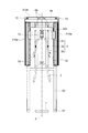
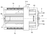
図3は、本発明の一実施形態にかかる介助装置を示した斜視図である。図4は、本発明の一実施形態にかかる介助装置を示した側面図である。図5は、本発明の一実施形態にかかる介助装置を示した正面図である。図6は、本発明の一実施形態にかかる介助装置を示した平面図である。図7は、本発明の一実施形態にかかる介助装置を図4のA−A方向から視認したA−A矢視図である。なお、図3〜図7において、上述したコントローラ4、動作検出センサ6、駆動指示装置8、及び音声認識センサ9などは不図示としている。
FIG. 3 is a perspective view showing an assistance device according to an embodiment of the present invention. FIG. 4 is a side view showing an assistance device according to an embodiment of the present invention. FIG. 5 is a front view showing an assistance device according to an embodiment of the present invention. FIG. 6 is a plan view showing an assistance device according to an embodiment of the present invention. FIG. 7 is an AA arrow view of the assistance device according to the embodiment of the present invention viewed from the AA direction in FIG. 4. 3 to 7, the controller 4, the
幾つかの実施形態では、図3〜図7に示すように、ハンドルは、上下方向に沿って延在する一対の把持部2aと、一対の把持部2aの先端部に夫々形成される湾曲状の一対のフック部2bと、一対の把持部2aの基端部を夫々連結する水平方向に延在する連結部2cとを含む。そして、連結部2cが、移動機構体3によって吊り支持されている。
In some embodiments, as shown in FIGS. 3 to 7, the handle has a pair of
このような実施形態によれば、把持部2aとフック部2bと連結部2cとからなるシンプルなハンドル構造とすることが出来る。また、被介助者Pは、後述するように、一対の把持部2aを両手で夫々把持しながら一対のフック部2bを両脇で夫々挟み込むような体勢でハンドル2に支持される。したがって、このような実施形態のハンドル2によれば、被介助者Pを安定した体勢で支持することが出来る。
According to such embodiment, it can be set as the simple handle structure which consists of the holding
幾つかの実施形態では、後述する図9Aの(b)、(c)などに示されるように、ハンドル2は、湾曲状のフック部2bの先端が下向きに傾くように前後方向に傾倒可能に構成される。
In some embodiments, as shown in FIGS. 9A and 9B described later, the
このような実施形態によれば、被介助者Pが一対のフック部2bを両脇で夫々挟み込むことを容易に行うことが出来る。
According to such an embodiment, it is easy for the person being assisted P to sandwich the pair of
幾つかの実施形態では、図3〜図7に示すように、移動機構体3は、ハンドル2を前後方向に移動させるための前後用アクチュエータ31と、ハンドル2を上下方向に移動させるための昇降用アクチュエータ32とを含む。
In some embodiments, as shown in FIGS. 3 to 7, the moving
図8は、本発明の一実施形態にかかる介助装置の一部品を構成する一般的な単軸アクチュエータを説明するための図である。
前後用アクチュエータ31および昇降用アクチュエータ32の各々は、図8に示すように、筐体51の内部に収容されているボールネジ52と、ボールネジ52を回転可能なサーボモータ53と、ボールネジ52の回転に伴い、ボールネジ52の延在方向に沿って移動可能なスライダ54とを有する単軸アクチュエータ50からなる。図8に示した実施形態では、ボールネジ52は、中間サポート55によって筐体51の内部に回転可能に収容されている。また、筐体51の開口部はカバー56で覆われている。このカバー56と筐体51との間にはスライダ54が移動可能な隙間aが形成されている。
FIG. 8 is a view for explaining a general single-axis actuator constituting one part of the assistance device according to the embodiment of the present invention.
As shown in FIG. 8, each of the front /
そして、上述した駆動制御部42は、サーボモータ53の回転を制御することで移動機構体3の駆動を制御するように構成されている。
The
このような実施形態によれば、汎用部品である単軸アクチュエータ50を使用して移動機構体3を構成することが出来るため、製造性、コスト性に優れている。
According to such an embodiment, since the moving
幾つかの実施形態では、図3〜図7に示すように、前後用アクチュエータ31は、前後用アクチュエータ31のスライダ54aに固定される、水平方向に延在する水平部31Ahおよび水平部31Ahの両端から下方に向かって延在する一対のアーム部31Aaを有する下向きU字状に形成された前後スライダ31Aを有する。水平部31Ahは、介助装置1の横方向に延在している。一対のアーム部31Aaの夫々には、2つの昇降用アクチュエータ32がアーム部31Aaの夫々に、アーム部31Aaの延在する方向に沿って固定される。そして、2つの昇降用アクチュエータ32は、2つの昇降用アクチュエータ32のスライダ54bに夫々固定される単一の昇降スライダ32Aを有しており、この昇降スライダ32Aにハンドル2が連結されている。
In some embodiments, as shown in FIGS. 3 to 7, the front /
さらに詳しく説明すると、図示した実施形態では、介助装置1は、床面上を水平方向に延在する一対の脚部61と、脚部61の一端部から上下方向に延在する一対の壁部62と、壁部62の先端から水平方向に延在する一対の頭部63とからなる、側面視でコの字状に形成される本体部60を有する。一対の頭部63の先端は、先端側連結部64によって連結され、その基端は、基端側連結部65によって連結されている。また、一対の頭部63の間には、先端側連結部64と基端側連結部65とを連結する支持部66が延在しており、この支持部66によって、前後方向に沿って配置される前後用アクチュエータ31が支持されている。また、一対の頭部63の各上面には、前後方向に沿ってガイドレール70が夫々取り付けられている。上述した前後スライダ31Aは、このガイドレール70に沿って案内されるように構成されている。また、昇降スライダ32Aとハンドル2とは、連結吊部72を介して連結されている。この連結吊部72は、昇降スライダ32Aに対して上下方向の軸線X周りに回転に連結されている。
More specifically, in the illustrated embodiment, the
このような実施形態によれば、1つの前後用アクチュエータ31と、2つの昇降用アクチュエータ32からなるシンプルな構造によって、ハンドル2を前後方向および上下方向の2軸に移動させることが出来る。
According to such an embodiment, the
最後に、本発明の一実施形態にかかる介助装置1の動作について説明する。先ず、被介助者Pが起立した状態から便器5に着座するまでの一連の動作について、図9A〜Cを基に説明する。
トイレ室のドアを開け、トイレ室の前に立った被介助者Pは(図9A(a))は、ハンドル2をフック部2bの先端が下向きに傾くように前後方向に傾倒させながら(図9A(b),(c))、フック部2bを両脇で挟み込むような体勢でターンテーブル7の上に起立する(図9B(d))。この時、両手はハンドル2の把持部2aを掴んでいる。
Finally, operation | movement of the
The person P who is standing in front of the toilet room with the door of the toilet room opened (FIG. 9A (a)) tilts the
そして、上述した駆動指示装置8のプッシュボタン8aをプッシュすると、ターンテーブル7がゆっくり回転し(図9B(e))、180度回転した後に停止する(図9B(f))。なお、ターンテーブル7は、プッシュボタン8aをプッシュしている間だけ回転駆動するようになっており、プッシュボタン8aのプッシュを止めると、ターンテーブル7は直ちに回転駆動を停止する。
When the push button 8a of the drive instruction device 8 described above is pushed, the
そして、便器5を背にして起立した状態(図9B(f))からさらにプッシュボタン8aをプッシュし続けると、移動機構体3が被介助者Pに対応する理想の移動軌跡(例えば、図4に示すT1)に基づいて、上下方向および前後方向の2軸方向に移動を開始する(図9C(g))。被介助者Pは、便器5に着座する動作中、ハンドル2によって支持される(図9C(h))。そして、被介助者Pは、便器5に着座した状態になると(図9C(i))、駆動指示装置8のプッシュボタン8aのプッシュを止める。これで、起立状態から便器5に着座するまでの一連の動作が完了する。
Then, when the push button 8a is further pushed from the state where the
この際、被介助者Pがプッシュボタン8aをプッシュし続けてしまうと、被介助者Pが用を足す前に次の便器5から起立する動作が始まってしまう虞がある。よって、起立状態から便器5に着座するまでの一連の動作が完了した場合は、プッシュボタン8aのプッシュを止め、改めてプッシュボタン8aをプッシュしないと、次の便器5から起立する動作が始まらないようにすることが出来る。また、上述した音声認識センサ9が被介助者Pの発する特定の音声を認識した場合に限って次の動作を開始するようにし、音声認識センサ9が被介助者Pの発する特定の音声を認識するまでは、プッシュボタン8aをプッシュしても次の動作が開始されないように構成してもよい。
At this time, if the person being assisted P continues to push the push button 8a, there is a possibility that the operation of standing up from the
次に、被介助者Pが便器5に着座した態から起立するまでの一連の動作について、図10A〜図10Cを基に説明する。
便器5に着座している被介助者P(図10A(a))が駆動指示装置8のプッシュボタン8aをプッシュすると、便器5から起立する動作が開始される。被介助者Pがプッシュボタン8aをプッシュし続けると(図10A(b))、移動機構体3が被介助者Pに対応する理想の移動軌跡(例えば図4に示すT2)に基づいて、上下方向および前後方向の2軸方向に移動を開始する(図10A(c))。被介助者Pは、便器5に着座する動作中、ハンドル2によって支持される(図10B(d))。そして、被介助者Pは、便器5の前に起立した状態になると(図10B(e))、便器5に着座した状態から起立するまでの一連の動作が完了する。そして、被介助者Pは、ハンドル2を持ち上げて両脇からハンドル2を外してトイレ室から出る(図10B(f)〜図10C(g))。
Next, a series of operations until the person being assisted rises from the state where the person P is seated on the
When the person P who is sitting on the toilet 5 (FIG. 10A (a)) pushes the push button 8a of the drive instruction device 8, the operation of standing up from the
介助者Pがトイレ室から退室すると、持ち上げられたハンドル2が自動的に元の初期状態に戻る(図10C(h))とともに、ハンドル2の回転位置が所定の初期状態(すなわち、図9A(a)に示した状態)となるように、ハンドル2が軸線X周りに自動的に回転する(図10C(i))。これらの駆動制御は、上述した退室認識部48及び駆動制御部42によって行われる。
またこの際、ターンテーブル7についても、ハンドル2と同様に、ターンテーブル7の回転位置が所定の初期状態となるように、自動的に回転させるように構成してもよい。
When the assistant P leaves the toilet room, the lifted
At this time, as with the
このような本発明の少なくとも一つの実施形態によれば、シンプルな構造で汎用性に優れるとともに、被介助者Pの着座から起立までの一連の動作において、被介助者にとって最も適した介助を行うことの出来る介助装置1を提供することが出来る。
According to such at least one embodiment of the present invention, the simple structure is excellent in versatility, and in the series of operations from sitting to standing of the person being assisted P, assistance most suitable for the person being assisted is performed. The
以上、本発明の好ましい形態について説明したが、本発明は上記の形態に限定されるものではない。例えば上述した実施形態を組み合わせても良く、本発明の目的を逸脱しない範囲での種々の変更が可能である。 As mentioned above, although the preferable form of this invention was demonstrated, this invention is not limited to said form. For example, the above-described embodiments may be combined, and various modifications can be made without departing from the object of the present invention.
1 介助装置
2 ハンドル
2a 把持部
2b フック部
2c 連結部
3 移動機構体
4 コントローラ
5 便器
6 動作検出センサ
7 ターンテーブル
8 駆動指示装置
8a プッシュボタン
9 音声認識センサ
31 前後用アクチュエータ
31A 前後スライダ
31Aa アーム部
31Ah 水平部
32 昇降用アクチュエータ
32A 昇降スライダ
41 軌跡認識部
42 駆動制御部
43 駆動指示受信部
44 軌跡記憶部
45 被介助者認識部
46 軌跡選定部
47 軌跡修正部
48 退室認識部
50 単軸アクチュエータ
51 筐体
52 ボールネジ
53 サーボモータ
54 スライダ
55 中間サポート
56 カバー
60 本体部
61 脚部
62 壁部
63 頭部
64 先端側連結部
65 基端側連結部
66 支持部
70 ガイドレール
72 連結吊部
P 被介助者
T1 理想の移動軌跡(着座動作)
T2 理想の移動軌跡(起立動作)
DESCRIPTION OF
T2 Ideal movement trajectory (stand-up motion)
Claims (15)
前記被介助者を支持可能なハンドルと、
前記ハンドルを上下方向の軸線周りに回転可能に吊り支持するとともに、前記ハンドルを上下方向および前後方向に移動させるための移動機構体と、
前記移動機構体の駆動を制御するためのコントローラと、を備え、
前記コントローラは、
前記被介助者が着座から起立までの一連の動作を行う際に前記ハンドルが描く移動軌跡であって前記被介助者に対応する理想の移動軌跡を認識可能な軌跡認識部と、
前記軌跡認識部が認識する理想の移動軌跡に基づいて、前記移動機構体の駆動を制御可能な駆動制御部と、を含む
介助装置。 An assistance device for assisting a series of operations from sitting to standing of a person being assisted,
A handle capable of supporting the person being assisted;
A suspension mechanism that supports the handle so as to be rotatable around an axis in the vertical direction, and a moving mechanism for moving the handle in the vertical direction and the front-rear direction;
A controller for controlling the driving of the moving mechanism body,
The controller is
A trajectory recognizing unit capable of recognizing an ideal trajectory corresponding to the person being assisted, which is a movement trajectory drawn by the handle when the person being assisted performs a series of operations from sitting to standing;
An assistance device including: a drive control unit capable of controlling driving of the moving mechanism body based on an ideal movement locus recognized by the locus recognition unit;
前記移動機構体の駆動に関する駆動指示信号を受信可能な駆動指示受信部をさらに含み、
前記駆動制御部は、
前記駆動指示信号に基づいて、前記移動機構体の駆動を進行または停止させるように制御する
請求項1に記載の介助装置。 The controller is
A drive instruction receiving unit capable of receiving a drive instruction signal related to driving of the moving mechanism body;
The drive control unit
The assistance apparatus according to claim 1, wherein the driving of the moving mechanism body is controlled to proceed or stop based on the driving instruction signal.
前記被介助者に対応する理想の移動軌跡を予め記憶する軌跡記憶部と、
不特定の被介助者の中から特定の被介助者を認識するための被介助者認識部と、
前記軌跡記憶部が記憶する理想の移動軌跡の中から、前記被介助者認識部が認識する前記被介助者に対応した理想の移動軌跡を選定するための軌跡選定部と、からなる
請求項1又は2に記載の介助装置。 The locus recognition unit
A trajectory storage unit that stores in advance an ideal movement trajectory corresponding to the person being assisted;
A caregiver recognition unit for recognizing a specific helper from unspecified helpers,
2. A trajectory selection unit for selecting an ideal movement trajectory corresponding to the person being assisted recognized by the person being assisted by the person being recognized from the ideal movement trajectory stored in the trajectory storage unit. Or the assistance apparatus of 2.
前記被介助者の動作を検出可能な動作検出センサをさらに備える
請求項3に記載の介助装置。 The assistance device is:
The assistance device according to claim 3, further comprising an operation detection sensor capable of detecting the operation of the person being assisted.
前記動作検出センサで検出される前記被介助者の動作に基づいて、前記軌跡記憶部に記憶される前記被介助者に対応する理想の移動軌跡を修正する軌跡修正部をさらに含む
請求項4に記載の介助装置。 The controller is
The trajectory correction part which correct | amends the ideal movement locus | trajectory corresponding to the said caregiver memorize | stored in the said locus | trajectory memory | storage based on the operation | movement of the said caregiver detected by the said motion detection sensor further. The assistance device described.
前記被介助者の発する音声を認識可能な音声認識センサをさらに備える
請求項3〜5の何れか一項に記載の介助装置。 The assistance device is:
The assistance apparatus as described in any one of Claims 3-5 further equipped with the speech recognition sensor which can recognize the audio | voice which the said care receiver utters.
前記音声認識センサが認識する前記被介助者の発する音声に基づいて、不特定の被介助者から特定の被介助者を認識するように構成されている
請求項6に記載の介助装置。 The care recipient recognition unit
The assistance device according to claim 6, configured to recognize a specific person to be assisted from an unspecified person to be assisted based on a sound uttered by the person to be assisted recognized by the voice recognition sensor.
前記ハンドルに支持されている前記被介助者の身体の向きを転向可能なターンテーブルをさらに備え、
前記駆動制御部は、
前記駆動指示信号に基づいて前記ターンテーブルの回転駆動を進行または停止させるように制御する
請求項2に記載の介助装置。 The assistance device is:
A turntable capable of turning the body of the person being supported by the handle;
The drive control unit
The assistance device according to claim 2, wherein the rotation drive of the turntable is controlled to proceed or stop based on the drive instruction signal.
前記駆動指示信号を発信可能な駆動指示装置をさらに備え、
前記駆動制御部は、
前記被介助者の体の向きを規定角度だけ転向させた後に、前記被介助者の着座から起立までの一連の動作を介助するように、
前記駆動指示装置のプッシュボタンがプッシュされている時には、前記移動機構体の駆動を進行させるか又は前記ターンテーブルの回転駆動を進行させ、前記プッシュボタンがプッシュされていない時には、前記移動機構体の駆動を停止させるか又は前記ターンテーブルの回転駆動を停止させるように構成される
請求項8に記載の介助装置。 The assistance device is:
A drive instruction device capable of transmitting the drive instruction signal;
The drive control unit
After turning the direction of the body of the person being assisted by a specified angle, so as to assist a series of operations from sitting to standing of the person being assisted.
When the push button of the drive instruction device is pushed, the drive of the moving mechanism is advanced or the rotation drive of the turntable is advanced, and when the push button is not pushed, The assistance device according to claim 8, configured to stop driving or to stop the rotation driving of the turntable.
上下方向に沿って延在する一対の把持部と、
前記一対の把持部の先端部に夫々形成される湾曲状の一対のフック部と、
前記一対の把持部の基端部を夫々連結する水平方向に延在する連結部と、を含み、
前記連結部が、前記移動機構体によって吊り支持されている
請求項1から9の何れか一項に記載の介助装置。 The handle is
A pair of gripping portions extending along the vertical direction;
A pair of curved hook portions respectively formed at the distal ends of the pair of gripping portions;
A connecting portion extending in the horizontal direction for connecting the base end portions of the pair of gripping portions, respectively,
The assistance device according to any one of claims 1 to 9, wherein the connecting portion is suspended and supported by the moving mechanism body.
前記ハンドルを前後方向に移動させるための前後用アクチュエータと
前記ハンドルを上下方向に移動させるための昇降用アクチュエータと、を含み、
前記前後用アクチュエータおよび前記昇降用アクチュエータの各々は、
筐体内に収容されているボールネジと、
前記ボールネジを回転可能なサーボモータと、
前記ボールネジの回転に伴い、前記ボールネジの延在方向に沿って移動可能なスライダと、を有する単軸アクチュエータからなり、
前記駆動制御部は、前記サーボモータの回転を制御することで前記移動機構体の駆動を制御する、
請求項1から11の何れか一項に記載の介助装置。 The moving mechanism is
A front-rear actuator for moving the handle in the front-rear direction, and an elevating actuator for moving the handle in the up-down direction,
Each of the front and rear actuators and the lift actuator is
A ball screw housed in the housing;
A servo motor capable of rotating the ball screw;
A slider that can move along the direction in which the ball screw extends along with the rotation of the ball screw,
The drive control unit controls driving of the moving mechanism body by controlling rotation of the servo motor.
The assistance device according to any one of claims 1 to 11.
前記一対のアーム部の夫々には、2つの前記昇降用アクチュエータが前記アーム部の夫々に固定されるとともに、前記2つの昇降用アクチュエータは、前記2つの昇降用アクチュエータのスライダに夫々固定される単一の昇降スライダを有し、前記昇降スライダに前記ハンドルが連結されている
請求項12に記載の介助装置。 The front / rear actuator is fixed to the slider of the front / rear actuator in a downward U-shape having a horizontal portion extending in the horizontal direction and a pair of arm portions extending downward from both ends of the horizontal portion. Having a front and rear slider formed,
In each of the pair of arm portions, two lifting actuators are fixed to each of the arm portions, and the two lifting actuators are fixed to the sliders of the two lifting actuators. The assistance device according to claim 12, further comprising: one lifting slider, wherein the handle is coupled to the lifting slider.
請求項1から13の何れか一項に記載の介助装置。 The assistance apparatus as described in any one of Claim 1 to 13 which consists of a toilet assistance apparatus provided in the toilet room where a toilet seat is arrange | positioned.
前記駆動制御部は、前記介助者が前記トイレ室から退室したことを前記退室認識部が認識すると、前記ハンドルの回転位置が所定の初期状態となるように、前記ハンドルを前記軸線周りに回転させるように構成される請求項14に記載の介助装置。
The controller further includes a leaving recognition unit capable of recognizing that the assistant has left the toilet room,
When the exit recognition unit recognizes that the assistant has left the toilet room, the drive control unit rotates the handle around the axis so that the rotation position of the handle is in a predetermined initial state. The assistance device according to claim 14 configured as described above.
Priority Applications (1)
| Application Number | Priority Date | Filing Date | Title |
|---|---|---|---|
| JP2014209328A JP2016077360A (en) | 2014-10-10 | 2014-10-10 | Assistance device |
Applications Claiming Priority (1)
| Application Number | Priority Date | Filing Date | Title |
|---|---|---|---|
| JP2014209328A JP2016077360A (en) | 2014-10-10 | 2014-10-10 | Assistance device |
Publications (1)
| Publication Number | Publication Date |
|---|---|
| JP2016077360A true JP2016077360A (en) | 2016-05-16 |
Family
ID=55956761
Family Applications (1)
| Application Number | Title | Priority Date | Filing Date |
|---|---|---|---|
| JP2014209328A Pending JP2016077360A (en) | 2014-10-10 | 2014-10-10 | Assistance device |
Country Status (1)
| Country | Link |
|---|---|
| JP (1) | JP2016077360A (en) |
Cited By (1)
| Publication number | Priority date | Publication date | Assignee | Title |
|---|---|---|---|---|
| WO2018047326A1 (en) * | 2016-09-12 | 2018-03-15 | 富士機械製造株式会社 | Assistance device |
-
2014
- 2014-10-10 JP JP2014209328A patent/JP2016077360A/en active Pending
Cited By (4)
| Publication number | Priority date | Publication date | Assignee | Title |
|---|---|---|---|---|
| WO2018047326A1 (en) * | 2016-09-12 | 2018-03-15 | 富士機械製造株式会社 | Assistance device |
| CN109689000A (en) * | 2016-09-12 | 2019-04-26 | 株式会社富士 | Jie helps device |
| CN109689000B (en) * | 2016-09-12 | 2021-05-28 | 株式会社富士 | Mediation device |
| US11096848B2 (en) | 2016-09-12 | 2021-08-24 | Fuji Corporation | Assistance device for identifying a user of the assistance device from a spoken name |
Similar Documents
| Publication | Publication Date | Title |
|---|---|---|
| US10166159B2 (en) | Care robot | |
| JP6788016B2 (en) | Assistance device | |
| JP2007295993A (en) | Training apparatus | |
| JP5481110B2 (en) | Dental treatment chair | |
| JPWO2015045010A1 (en) | Assistance robot | |
| KR20200105076A (en) | MOBILE and TRANSFERRING ROBOT FOR HANDICAPED PERSON | |
| JP6490517B2 (en) | Transfer support system | |
| WO2014029988A1 (en) | Leg lifter apparatus | |
| JP3792481B2 (en) | Walking assist device | |
| JP5601364B2 (en) | Transfer support device and control method of transfer support device | |
| CN109688998B (en) | Mediation device | |
| JP2016077360A (en) | Assistance device | |
| JP5239776B2 (en) | Transfer support device and control method of transfer support device | |
| AU2016336279B2 (en) | Assistance device | |
| JP4903000B2 (en) | Stand-up support device | |
| JP5239821B2 (en) | Transfer support device and control method of transfer support device | |
| JP6233057B2 (en) | Nursing care support device | |
| JP5609956B2 (en) | Transfer support device and control method of transfer support device | |
| JP6306769B2 (en) | Mobility assist robot | |
| JP5423867B2 (en) | Transfer support device and control method of transfer support device | |
| JP5609955B2 (en) | Transfer support device and control method of transfer support device | |
| JP2017000190A (en) | Motion support device | |
| JP2007082813A (en) | Training apparatus | |
| JP2012105916A (en) | Movement assisting device for person in need of nursing care | |
| JP6989701B2 (en) | Caregiving device management device |