JP2016071041A - Image forming apparatus - Google Patents
Image forming apparatus Download PDFInfo
- Publication number
- JP2016071041A JP2016071041A JP2014198489A JP2014198489A JP2016071041A JP 2016071041 A JP2016071041 A JP 2016071041A JP 2014198489 A JP2014198489 A JP 2014198489A JP 2014198489 A JP2014198489 A JP 2014198489A JP 2016071041 A JP2016071041 A JP 2016071041A
- Authority
- JP
- Japan
- Prior art keywords
- recording material
- image forming
- forming apparatus
- contact portion
- toner
- Prior art date
- Legal status (The legal status is an assumption and is not a legal conclusion. Google has not performed a legal analysis and makes no representation as to the accuracy of the status listed.)
- Pending
Links
Images


Landscapes
- Electrostatic Charge, Transfer And Separation In Electrography (AREA)
- Control Or Security For Electrophotography (AREA)
- Feeding Of Articles By Means Other Than Belts Or Rollers (AREA)
Abstract
Description
本発明は、プリンタ、ファクシミリ、複写機、及び複合機等の、記録紙等のシート状の記録材上にトナーを付着させて画像を形成する画像形成装置に関するものである。 The present invention relates to an image forming apparatus that forms an image by attaching toner onto a sheet-like recording material such as recording paper, such as a printer, a facsimile machine, a copying machine, and a multifunction machine.
従来から、トナーを付着させる画像記録部を通過する記録材の搬送経路内で、搬送される記録材を案内する単数又は複数の搬送ガイドを備えた画像形成装置が知られている。 2. Description of the Related Art Conventionally, an image forming apparatus including one or a plurality of conveyance guides for guiding a recording material to be conveyed in a conveyance path of a recording material that passes through an image recording unit to which toner is attached is known.
例えば、特許文献1には、次のような画像形成装置が記載されている。
トナー(トナー像)を表面上に担持して表面移動する像担持体(中間転写ベルト)と、像担持体上のトナー像を記録材(シート)に付着させる(二次転写する)画像記録部(二次転写部)とを備えている。そして、画像記録部を通過する記録材を案内する搬送ガイドを、画像記録部の記録材搬送方向上流側(以下、上流側という。)、又は記録材搬送方向下流側(以下、下流側という。)の近傍に設けている。
これらの搬送ガイドには、記録材搬送方向に直交する記録材幅方向(以下、幅方向という。)の記録材の両端部に、それぞれ外側から当接して記録材を案内する一対の移動可能な端部当接部(サイド規制板)を搬送ガイドに設けている。これらの端部当接部の位置は、画像記録部の上流側に設けられたレジスト部で幅方向の位置が調整された記録材の幅方向の長さに連動して制御され、レジスト部を通過した後、記録材が画像記録部を通過するまでに斜行してしまう(斜送される)ことを防止している。
For example,
An image carrier (intermediate transfer belt) that carries toner (toner image) on the surface and moves on the surface, and an image recording unit that attaches (secondarily transfers) the toner image on the image carrier to a recording material (sheet) (Secondary transfer portion). A conveyance guide for guiding the recording material passing through the image recording unit is referred to as an upstream side in the recording material conveyance direction (hereinafter referred to as an upstream side) or a downstream side in the recording material conveyance direction (hereinafter referred to as a downstream side). ).
A pair of movable guides that guide the recording material by contacting the both ends of the recording material in the recording material width direction (hereinafter referred to as the width direction) perpendicular to the recording material conveyance direction from the outside respectively. An end contact portion (side regulating plate) is provided in the conveyance guide. The positions of these end contact portions are controlled in conjunction with the length in the width direction of the recording material whose position in the width direction is adjusted by the resist portion provided on the upstream side of the image recording portion. After passing, the recording material is prevented from being skewed (passed forward) before passing the image recording portion.
特許文献1に記載の画像形成装置では、上記のような搬送ガイドを備えることで、幅方向のサイズが異なる複数種類の記録材に対してトナー像の転写を行う場合であっても、記録材に対するトナー像の幅方向の転写位置を、記録材幅に応じた最適な位置にできる。
しかし、幅方向のサイズが異なる複数種類の記録材に対して画像形成を行う場合には、次のような問題が生じる場合がある。
In the image forming apparatus described in
However, when image formation is performed on a plurality of types of recording materials having different sizes in the width direction, the following problems may occur.
特許文献1の画像形成装置ではどのようなものを設けているか不明であるが、一般的な画像形成装置には、案内する記録材の表裏のいずれかの面に当接する面部当接部を有した転写入口ガイド等の搬送ガイドを備えていることが多い。
そして、トナー像を転写する画像形成装置では、潜像担持体の静電潜像にトナーを付着させてトナー像を形成する現像工程、像担持体に担持したトナー像を記録材に転写する転写工程、及び像担持体上の転写残トナーをクリーニングするクリーニング工程が行われる。これらの工程では、画像形成装置内(以下、装置内という。)にトナーが飛散したり、現像装置やクリーニング装置からトナー落ちが生じたりする。
これらの飛散したトナーやトナー落ちしたトナーは、記録材を搬送する搬送経路内に設けられた搬送ガイドの面部当接部に付着してしまう。
Although it is unclear what is provided in the image forming apparatus of
In the image forming apparatus for transferring the toner image, a developing process for forming the toner image by attaching toner to the electrostatic latent image on the latent image carrier, and a transfer for transferring the toner image carried on the image carrier to a recording material. A process and a cleaning process for cleaning the transfer residual toner on the image carrier are performed. In these steps, toner is scattered in the image forming apparatus (hereinafter referred to as “inside the apparatus”), or toner is dropped from the developing device and the cleaning device.
The scattered toner and the toner that has fallen out of toner adhere to the surface contact portion of the conveyance guide provided in the conveyance path for conveying the recording material.
画像形成を行う毎に面部当接部に付着するトナー量は通常は僅かな量であり、最大幅サイズの記録材に画像形成を行っている間は、記録材が擦動する毎に付着したトナーが拭き(掻き)取られて、面部当接部の幅方向全域がクリーニングされた状態となる。これらのため、面部当接部から拭き取ったトナーが記録材に付着しても、裏汚れ等の目視できる汚れとなる問題が発生することはない。 The amount of toner adhering to the surface abutting portion every time image formation is performed is usually a small amount. During image formation on a recording material of the maximum width size, the toner adhering every time the recording material is rubbed. The toner is wiped (scraped), and the entire area in the width direction of the surface contact portion is cleaned. For this reason, even if the toner wiped off from the surface contact portion adheres to the recording material, there is no problem of causing visible stains such as back stains.
一方、幅方向のサイズが、最大幅サイズよりも小さな記録材(例えばA5Y)に画像形成を行っている間は、記録材幅の領域内のトナーは、記録材が擦動する毎に拭き取られるが、記録材幅の領域外のトナーは拭き取られず面部当接部に蓄積されてしまう。このように蓄積された状態で、幅方向のサイズがより大きな記録材(例えばA4Y)に画像形成を行うと、小さなサイズの記録材幅の領域外に蓄積したトナーが大きなサイズの記録材に拭き取られて、裏汚れ等の目視できる汚れとなる問題が生じるおそれがある。 On the other hand, while image formation is being performed on a recording material (for example, A5Y) whose size in the width direction is smaller than the maximum width size, the toner in the recording material width area is wiped off every time the recording material is rubbed. However, the toner outside the area of the recording material width is not wiped off and is accumulated in the surface contact portion. When an image is formed on a recording material having a larger size in the width direction (for example, A4Y) in the accumulated state, the toner accumulated outside the area of the small recording material width is wiped to the large recording material. There is a possibility that a problem that it becomes visible and stains such as back stains may occur.
本発明は以上の問題点に鑑みなされたものであり、その目的は、次のような画像形成装置を提供することである。
搬送方向に直交する幅方向の長さが異なる記録材に画像形成可能な画像形成装置であって、記録材の表裏のいずれかの面に当接する面部当接部を有した搬送ガイドを介して、トナーが記録材に付着して汚れることを抑制できる画像形成装置である。
The present invention has been made in view of the above problems, and an object thereof is to provide the following image forming apparatus.
An image forming apparatus capable of forming an image on a recording material having a different length in the width direction perpendicular to the conveyance direction, via a conveyance guide having a surface portion abutting portion that abuts on either the front or back surface of the recording material The image forming apparatus can prevent the toner from adhering to the recording material and becoming dirty.
上記目的を達成するために、請求項1に記載の発明は、トナーを付着させる画像記録部を通過する記録材の搬送経路内で、搬送される記録材を案内する単数又は複数の搬送ガイドと、を備えた画像形成装置において、前記搬送ガイドの少なくとも1つは、案内する記録材の表裏のいずれかの面に当接する面部当接部を有し、該面部当接部の記録材搬送方向に直交する記録材幅方向の長さを変更できることを特徴とするものである。
In order to achieve the above object, the invention described in
本発明によれば、次のような画像形成装置を提供できる。
搬送方向に直交する幅方向の長さが異なる記録材に画像形成可能な画像形成装置であって、記録材の表裏のいずれかの面に当接する面部当接部を有した搬送ガイドを介して、トナーが記録材に付着して汚れることを抑制できる画像形成装置である。
According to the present invention, the following image forming apparatus can be provided.
An image forming apparatus capable of forming an image on a recording material having a different length in the width direction perpendicular to the conveyance direction, via a conveyance guide having a surface portion abutting portion that abuts on either the front or back surface of the recording material The image forming apparatus can prevent the toner from adhering to the recording material and becoming dirty.
以下、本発明を電子写真方式のレーザビームプリンタ(以下、プリンタ100という。)に適用した一実施形態について説明する。まず、プリンタ100の全体構成及び動作について、図を用いて説明する。
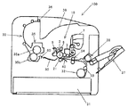
図1は、本実施形態に係るプリンタ100の構成を示す概略構成図である。
Hereinafter, an embodiment in which the present invention is applied to an electrophotographic laser beam printer (hereinafter referred to as a printer 100) will be described. First, the overall configuration and operation of the
FIG. 1 is a schematic configuration diagram illustrating a configuration of a
図1に示すように、このプリンタ100は、機枠体のほぼ中央部に像担持体(潜像担持体)としての感光体ドラム1を設けた作像部10を備えている。この作像部10の下方には、作像部10で形成された感光体ドラム1上のトナー像を、記録材としての記録紙Pに転写する転写ローラ21を備えている。この転写ローラ21は、感光体ドラム1の表面上(以下、感光体ドラム1上)に形成したトナー像を記録紙Pに転写する画像記録部としての転写ニップ部Nを感光体ドラム1とで形成している。
As shown in FIG. 1, the
また、装置本体の下部には、記録紙Pを積載して収容する収容部材としての給紙カセット31、給紙カセット31から記録紙Pを順次、感光体ドラム1と転写ローラ21との間に形成される転写ニップ部N(図2参照)に向けて送り出す給紙ローラ32を備えている。
また、作像部10の図中右方には、装置本体側面に対して開閉可能に設けられた記録紙積載装置としての手差しトレイ37を備えている。この手差しトレイ37の記録紙搬送方向下流側端近傍にも、手差しトレイ37上に積載された記録紙Pを転写ニップ部Nに向けて順次、送り出す手差しトレイ給紙ローラ38が設けられている。
ここで、給紙カセット31及び手差しトレイ37は、記録紙Pとして複数のサイズ(例えば、A5YやA4Y)を積載可能に構成されており、プリンタ100も複数のサイズ(記録紙搬送方向に直交する記録紙幅)の記録紙Pに対して画像形成が可能である。
Further, in the lower part of the apparatus main body, a
Further, on the right side of the
Here, the
また、作像部10の図中左方(転写ニップ部Nの記録紙搬送方向下流側)には、記録紙P上のトナー像を定着する定着装置35などを備えている。
また、装置本体上部には、定着装置35を通過した記録紙Pを機外に排出する排紙ローラ対36(図1では一方のローラを記載)から排紙された記録紙Pを積載する積載トレイ39が設けられている。
また、給紙カセット31又は手差しトレイ37から給紙された記録紙Pを一旦停止させ、感光体ドラム1上に担持されたトナーの転写ニップ部Nへの進入タイミングに合わせて、記録紙Pを送り出すレジスト部としてレジストローラ対34が設けられている。
A
Further, on the upper part of the apparatus main body, the recording paper P discharged from a pair of paper discharge rollers 36 (one roller is shown in FIG. 1) for discharging the recording paper P that has passed through the
Further, the recording paper P fed from the
そして、本実施形態のプリンタ100は、給紙カセット31又は手差しトレイ37から積載トレイ39に搬送する記録紙Pの搬送経路内の、レジストローラ対34から転写ニップ部Nに至る記録紙Pの搬送方向が、略水平方向である横搬送型のものである。
また、記録紙Pの搬送経路内には、搬送される記録紙Pを案内する転写入口ガイド40、転写出口ガイド50、及び定着入口ガイド等の複数の搬送ガイドや、複数の搬送ローラ対33(図1では一方のローラを記載)を備えている。
The
Further, in the conveyance path of the recording paper P, a plurality of conveyance guides such as a
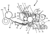
図2は、プリンタ100の作像部10付近の概略構成図である。
感光体ドラム1周囲の作像部10には感光体ドラム1の回転方向(図中矢印a)に対し順に帯電手段としての帯電ローラ2、光書込み手段としての露光装置6、現像手段としての現像装置3、クリーニング手段としての感光体クリーニング装置5が設けられている。そして、現像装置3と感光体クリーニング装置5の間の感光体ドラム1の表面に記録紙Pの搬送経路30を介して対向する下方の位置には転写ローラ21が設けられ、感光体ドラム1とで転写ニップ部Nを形成している。
なお、感光体ドラム1と、その周囲に配設される帯電ローラ2、現像装置3、及び感光体クリーニング装置5は、プロセスカートリッジとして共通の支持体に支持され、装置本体に対して一体に着脱可能になっている。また、現像装置3の上方には、現像装置3で消費された現像剤を補給する現像剤補給装置7が設けられている(図1参照)。
FIG. 2 is a schematic configuration diagram of the vicinity of the
The
The
転写ニップ部Nの記録紙搬送方向上流側には、レジストローラ対34と、レジストローラ対34により送り出される記録紙Pの下面(裏面)に当接する面部当接部を有し、転写ニップ部Nに向けて案内する転写入口ガイド40を備えている。
転写ニップ部Nの記録紙搬送方向下流側には、転写後の記録紙Pの下面に当接する面部当接部を有し、定着装置35に向けて案内する転写出口ガイド50を備えている。また、転写出口ガイド50の記録紙搬送方向下流側には、転写出口ガイド50上を通過した記録紙Pの下面に当接する面部当接部を有し、定着装置35の定着ニップ部に向けて案内する定着入口ガイド60も備えている。
On the upstream side of the transfer nip portion N in the recording paper conveyance direction, there are a
On the downstream side of the transfer nip N in the recording paper conveyance direction, a
感光体ドラム1は、例えば、直径30mmの負帯電の有機感光体で、アルミニウム製のドラム基体上(不図示)に感光体層(不図示)を有している。そして、感光体駆動モータ(不図示)の駆動により所定の周速で矢印a方向(時計方向)に回転駆動され、その回転過程において接触する帯電ローラ2により負極性の一様な帯電を受ける。
帯電ローラ2は、接触帯電方式のものであり、感光体ドラム1表面に回転自在に接触し、帯電バイアス電源(不図示)から印加される帯電バイアス(直流成分に交流成分を重畳したバイアス)によって感光体ドラム1を負極性の所定電位に均一に帯電する。
露光装置6は、ホストコンピュータ(不図示)等の外部機器から入力される画像情報の時系列デジタル画像信号に応じて変調したLED光をLEDアレイから出力し、感光体ドラム1表面を露光することで画像情報に応じた静電潜像を感光体ドラム1表面に形成する。
The
The charging
The
現像装置3は、一成分現像方式の現像装置であり、現像容器3aの開口部に感光体ドラム1と対向配置された回転自在な現像剤担持体としての現像ローラ3eを備えている。そして、現像ローラ3e表面に担持した現像剤(トナー)を感光体ドラム1表面の静電潜像に付着させてトナー像として現像(可視像化)するものである。
現像容器3a内のトナーは、攪拌部材3c等によって攪拌されて供給ローラ3bより現像ローラ3e側に供給される。現像ローラ3e表面に供給されたトナーは規制ブレード3dにより層厚規制を受けて所定層厚に形成される。
また、現像ローラ3eには、現像バイアス電源(不図示)から直流成分に交流成分を重畳した所定の現像バイアスが印加される。
The developing
The toner in the developing
A predetermined developing bias in which an AC component is superimposed on a DC component is applied to the developing
転写ローラ21は、付勢手段(不図示)にて所定の押圧力で、感光体ドラム1表面に向けて付勢されて接触しており、感光体ドラム1とで転写ニップ部Nを形成する接触転写方式のものである。この転写ローラ21は、転写バイアス電源(不図示)から印加される転写バイアスにより、感光体ドラム1と転写ローラ21と間に形成される転写ニップ部Nにて、感光体ドラム1表面のトナー像を記録紙P上に転写するとともに、反時計方向に回転される。
ここで、給紙カセット31から給紙され、レジストローラ対34により転写ニップ部Nに向けて搬送される記録紙Pは、転写ニップ部Nに進入する際、転写入口ガイド40の面部当接部に擦動しながら案内される。
The
Here, when the recording paper P fed from the
感光体クリーニング装置5は、クリーニングケース5aにクリーニングブレード5bを設けており、トナー像が転写された後の感光体ドラム1表面に残留している転写残トナーを、クリーニングブレード5bで掻き取るようにして除去してクリーニングする。そして、感光体ドラム1上から除去された転写残トナーは、廃トナー容器を兼ねるクリーニングケース5a内に回収される。
The
定着装置35は、定着ローラ35aと加圧ローラ35bを有しており、定着ローラ35aと加圧ローラ35b間の定着ニップにて記録紙Pを挟持搬送しながら、記録紙Pの表面に転写されたトナー像を加熱加圧して熱定着する。
ここで、転写後の記録紙Pは、下方から当接する転写出口ガイド50及び定着入口ガイド60の面部当接部に擦動しながら案内されて、定着装置35の定着ニップ部に進入する。
The fixing
Here, the recording paper P after the transfer is guided while being rubbed against the surface contact portions of the
次に、プリンタ100による画像形成動作について説明する。
外部機器から画像情報が入力されると、感光体ドラム1は感光体駆動モータの駆動により矢印a方向(時計方向)に所定の周速(例えば180mm/sec)で回転駆動され、帯電ローラ2により、表面が所定電位に一様帯電される。一様帯電された感光体ドラム1上に露光装置6により、走査光Lが露光されることにより、感光体ドラム1上の電位は露光された部分の電位が低下して、入力される画像信号に応じた静電潜像が形成される。
その後、形成された静電潜像に、現像位置にて感光体ドラム1の帯電極性(負極性)と同極性の現像バイアスが印加された現像装置3の現像ローラ3eにより、感光体ドラム1の帯電極性と同極性に帯電されたトナーを付着させて、トナー像として反転現像する。
Next, an image forming operation by the
When image information is input from an external device, the
Thereafter, the developing
また、感光体駆動モータの駆動と略同時に、給紙カセット31から給紙ローラ32によって、もしくは、手差しトレイ37から手差し給紙ローラ38によって、記録紙Pが1枚ずつ分離して搬送され、レジストローラ対34に突き当たることによって止められる。このレジストローラ対34に突き当たって、一旦止められた記録紙Pは、作像部10(感光体ドラム1)のトナー像形成のタイミングに合わせて、レジストローラ対34が回転駆動されて転写ニップNに送り出される。具体的には、感光体ドラム1上のトナー像が感光体ドラム1と転写ローラ21の間に形成される転写ニップNに到達するタイミングに合わせて、停止させていたレジストローラ対34を回転駆動して記録紙Pを転写ニップ部Nに進入させる(搬送する)。
このとき、記録紙Pは、転写入口ガイド40に擦動しながら案内されて、ジャムが発生しないように転写ニップ部に所定の姿勢で進入する(搬送される)。
そして、感光体ドラム1上に付着したトナーとは逆極性(正極性)の転写バイアスが印加された転写ローラ21により、感光体ドラム1と転写ローラ21間に発生する静電力で、感光体ドラム1上のトナー像が転写ニップ部Nに搬送された記録紙Pに転写される。
The recording paper P is separated and conveyed one by one by the
At this time, the recording paper P is guided while being rubbed to the
The photosensitive drum is driven by an electrostatic force generated between the
トナー像が転写された記録紙Pは、感光体ドラム1から分離し、転写出口ガイド50の面部当接部に擦動しながら案内されて、定着装置35に向かって搬送される。そして、定着入口ガイド60の面部当接部に擦動しながら案内されて、ジャムが発生しないように定着装置35の定着ニップ部に進入する(搬送される)。
定着ニップ部に進入した記録紙Pは、定着ニップ部で加熱及び加圧されて、転写されたトナー像が記録紙P上に熱定着される。
一方、トナー像が記録材Pに転写された後の感光体ドラム1上の転写残トナーは、感光体ドラム1の回転にともない、感光体クリーニング装置5のクリーニングブレード5によりクリーニングされる。そして、クリーニングされた転写残トナーは廃トナー容器を兼ねるクリーニングケース5a内に回収される。
The recording paper P onto which the toner image has been transferred is separated from the
The recording paper P that has entered the fixing nip portion is heated and pressurized in the fixing nip portion, and the transferred toner image is heat-fixed on the recording paper P.
On the other hand, the untransferred toner on the
そして、定着装置35を通過した記録紙Pは、搬送経路30内を複数の搬送ローラ対33(図1では符号を省略)により排紙ローラ対36まで搬送され、排紙ローラ対36により機外の積載トレイ39上に排紙されて、一連の画像形成動作を終了する。
Then, the recording paper P that has passed through the fixing
ここで、本実施形態のプリンタ100のように、トナー像を転写する電子写真方式の画像形成装置では、次のような工程を有している。感光体ドラム1などの潜像担持体の静電潜像にトナーを付着させてトナー像を形成する現像工程、感光体ドラム1や中間転写ベルトなどの像担持体に担持したトナー像を転写する転写工程、像担持体上の転写残トナーをクリーニングするクリーニング工程である。これらの工程では、画像形成装置内(以下、装置内という。)にトナーが飛散したり、現像装置やクリーニング装置からトナー落ちが生じたりする。
そして、飛散したトナーやトナー落ちしたトナーが、記録紙Pを搬送する搬送経路内に設けられた転写入口ガイド40、転写出口ガイド50、及び定着入口ガイドなどの搬送ガイドの、記録材の下面(裏面)に当接する面部当接部に付着してしまう場合がある。
Here, like the
Then, the scattered toner or the toner that has fallen out of the toner is transferred to the lower surface of the recording material of the conveyance guides such as the
画像形成を行う毎に面部当接部に付着するトナー量は通常は僅かな量であり、最大幅サイズの記録紙Pに画像形成を行っている間は、記録紙Pが擦動する毎に付着したトナーが拭き(掻き)取られて、面部当接部の幅方向全域がクリーニングされた状態となる。これらのため、面部当接部から拭き取ったトナーが記録紙Pに付着しても、裏汚れ等の目視できる汚れとなる問題が発生することはない。つまり、面部当接部の幅方向全域に擦動する最大幅サイズの記録材に画像形成を行っている間は、搬送ガイドの面部当接部を介して、記録紙Pに付着するトナー量を、製品規格内の記録材の汚れが発生する量に留めることができる。 Each time image formation is performed, the amount of toner adhering to the surface contact portion is usually a small amount, and every time the recording paper P is rubbed during image formation on the maximum width size recording paper P. The adhered toner is wiped (scraped), and the entire area in the width direction of the surface contact portion is cleaned. For this reason, even if the toner wiped off from the surface contact portion adheres to the recording paper P, there is no problem of causing visible stains such as back stains. That is, while an image is being formed on the recording material of the maximum width size that rubs over the entire width direction of the surface contact portion, the amount of toner adhering to the recording paper P is measured via the surface contact portion of the conveyance guide. Therefore, the recording material can be kept within an amount within the product standard.
一方、幅方向のサイズが、最大幅サイズよりも小さな記録紙P(例えばA5Y)に画像形成を行っている間は、記録紙幅の領域内のトナーは、記録紙Pが擦動する毎に拭き取られるが、記録紙幅の領域外のトナーは拭き取られず面部当接部上に蓄積されてしまう。このように蓄積された状態で、幅方向のサイズが大きな記録紙P(例えばA4Y)に画像形成を行うと、小さなサイズの記録紙幅の領域外に蓄積したトナーが大きなサイズの記録紙Pに拭き取られて、裏汚れ等の目視できる汚れとなる問題が生じるおそれがある。つまり、幅サイズが小さな記録紙Pに画像形成を行った後に大きな幅サイズの記録紙Pに画像形成を行うと、搬送ガイドの面部当接部を介して、大きな幅サイズの記録紙Pに付着するトナー量が、製品規格外の記録紙Pの汚れが発生する量になるおそれがある。 On the other hand, while the image is being formed on the recording paper P (for example, A5Y) whose size in the width direction is smaller than the maximum width size, the toner in the area of the recording paper width is wiped every time the recording paper P is rubbed. However, the toner outside the recording paper width region is not wiped off and is accumulated on the surface contact portion. When an image is formed on the recording paper P having a large width in the accumulated state (for example, A4Y), the toner accumulated outside the area of the small recording paper width is wiped onto the large recording paper P. There is a possibility that a problem that it becomes visible and stains such as back stains may occur. That is, if an image is formed on a recording sheet P having a large width after an image is formed on the recording sheet P having a small width size, it adheres to the recording sheet P having a large width through the surface contact portion of the conveyance guide. There is a possibility that the amount of toner to be used will be an amount that causes the recording paper P outside the product standards to be stained.
特に、本実施形態のプリンタ100のように、一成分現像方式の現像装置3を備える構成は、一般的に、二成分現像方式の現像装置よりも部品点数が少なくなるため、低コストで現像装置を提供できるメリットがあるものの、上記問題がより顕著となり易い。これは次の理由による。
一般的に、一成分現像方式の現像装置は、二成分現像方式の現像装置に比べて、潜像担持体の「地肌汚れ」が悪く、現像装置からの「トナー吐き出し」が多い。
In particular, the configuration including the one-component developing
In general, a one-component developing type developing device has a worse “background stain” of the latent image carrier and more “toner discharge” from the developing device than a two-component developing type developing device.
「地肌汚れ」は、非作像部分(白紙部分)にトナーが付着してしまう現象であり、地肌汚れが悪い画像形成装置では、機内のトナー飛散量が多くなり、搬送経路を汚してしまう。
「トナー吐き出し」は、現像装置内のトナーが劣化した場合にも意図的に行われ、これにより機内のトナー飛散量が多くなり、搬送経路を汚してしまう。例えば、低画像面積率、低P/J(1ジョブ当たりの印刷枚数)の出力が続くと、現像装置内のトナーが劣化し易くなり、劣化トナーを感光体ドラム等の潜像担持体に放出する「トナー吐き出し」の頻度が高まる。特に、一成分現像方式の現像装置ではトナーの劣化に対して不利で、吐き出し回数、量も多くなる。
“Background stain” is a phenomenon in which toner adheres to a non-imaged portion (blank paper portion). In an image forming apparatus with poor background stain, the amount of toner scattered in the apparatus increases, and the conveyance path becomes dirty.
“Toner discharge” is also performed intentionally even when the toner in the developing device deteriorates. As a result, the amount of toner scattered in the apparatus increases, and the conveying path becomes dirty. For example, if the output of a low image area ratio and low P / J (number of printed sheets per job) continues, the toner in the developing device tends to deteriorate, and the deteriorated toner is released to a latent image carrier such as a photosensitive drum. The frequency of “toner discharge” increases. In particular, a one-component developing type developing device is disadvantageous for toner deterioration, and the number and the number of discharges are increased.
なお、像担持体と転写ローラとで形成される画像記録部である転写ニップ部で、像担持体から転写ローラの非通紙部に転写残トナー等のトナーが付着することを防ぐ構成に関して、特許文献2には、次のような画像形成装置が記載されている。記録紙の最小幅に対応する長さを有する転写ローラ、及びそれ以下の長さを有する転写ローラを含む複数本の転写ローラを備えている。そして、複数本の転写ローラのうち少なくとも1本を、トナー像を転写する記録紙の幅に応じて横移動させ、全体として転写紙の幅に対応する転写ローラ幅を得るという構成である。このように、像担持体とで転写ニップ部を形成する転写ローラを構成することで、像担持体から転写ローラの非通紙部に転写残トナー等のトナーが付着することを防ぐことができるというものである。そして、転写ローラの非通紙部にトナーが付着することを防ぐことで、転写効率が低下したり、次の通紙される記録紙に裏汚れが発生したりすることを抑制できるものである。
Regarding the configuration for preventing toner such as transfer residual toner from adhering to the non-sheet passing portion of the transfer roller from the image carrier at the transfer nip portion which is an image recording portion formed by the image carrier and the transfer roller.
しかし、特許文献1には、記録紙を搬送する搬送経路内に設けられ、記録紙の表裏のいずれかの面が擦動する面部当接部を有した搬送ガイドに関する記載や、飛散トナー等が面部当接部を有した搬送ガイドに付着することに関する記載はない。
このため、本実施形態のプリンタ100で解決しようとしている、飛散トナーやトナー落ちしたトナーが搬送ガイドの面部当接部に付着して、記録紙を汚してしまうという問題を解決できるか否か不明である。
However,
For this reason, it is unclear whether or not the problem that the
そこで、発明者らは、搬送方向に直交する幅方向の長さが異なる記録材Pに画像形成可能で、記録紙Pの表裏のいずれかの面が擦動する面部当接部を有した搬送ガイドを介して、トナーが記録紙Pに付着して汚れることを抑制できる画像形成装置の構成を検討した。
なお、上記問題は、一成分現像方式の現像装置を備えた画像形成装置でのみ発生する問題ではなく、例えば、二成分現像方式の現像装置を備えた、搬送方向に直交する幅方向の長さが異なる記録材に画像形成可能な画像形成装置でも発生し得る問題である。
Therefore, the inventors can form an image on a recording material P having different lengths in the width direction orthogonal to the transport direction, and have a transport portion having a surface contact portion on which either the front or back surface of the recording paper P is rubbed. The configuration of the image forming apparatus that can suppress the toner from adhering to the recording paper P and being contaminated through the guide was studied.
Note that the above problem is not a problem that occurs only in an image forming apparatus equipped with a one-component developing type developing device. For example, the length in the width direction perpendicular to the transport direction is equipped with a two-component developing type developing device. However, the problem may occur even in an image forming apparatus capable of forming an image on different recording materials.
次に、発明者らが検討して得た、記録紙Pの表裏のいずれかの面が擦動する面部当接部を有した搬送ガイドを介して、トナーが記録紙Pに付着して汚れることを抑制できる画像形成装置の構成について、本実施形態のプリンタ100に適用した例について説明する。
ここで、本実施形態のプリンタ100では、上記したように感光体ドラム1を、記録紙Pの搬送経路(転写ニップ部Nを通過する記録紙P)の上方に設けている。このため、表面が下方に回転する感光体ドラム1からのトナー飛散や、現像装置3からのトナー落ちが生じ易く、面部当接部上にトナーが蓄積し易い転写入口ガイド40に、本発明を適用した例について、図を用いて説明する。
Next, the toner adheres to the recording paper P and becomes dirty through a conveyance guide having a surface portion contact portion on which either of the front and back surfaces of the recording paper P, which is obtained by the inventors, is rubbed. An example in which the configuration of the image forming apparatus that can suppress this is applied to the
Here, in the
以下の説明で用いる図3〜図8は、いずれも感光体ドラム1付近を記録紙搬送方向上流側から見た斜視説明図である。
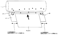
まず、図3、図4を用いて従来の問題点を具体的に説明する。
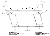
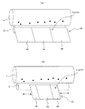
図3は、幅方向の長さが短い小さなサイズ、例えば、A5Yサイズの記録紙Pを通紙するときに、転写入口ガイド40の面部当接部41上のA5Y紙幅領域外にトナーが蓄積してしまう従来の問題の斜視説明図である。図4は、図3に示したA5Y紙幅領域外に蓄積したトナーが、その後、通紙するA4Yサイズの記録紙Pの、A5Y紙幅領域外に付着して、A4Yサイズの記録紙Pに目視できる裏汚れが発生する問題の斜視説明図である。
3 to 8 used in the following description are perspective explanatory views when the vicinity of the
First, the conventional problems will be specifically described with reference to FIGS.
FIG. 3 shows that when passing a small size, for example, A5Y size recording paper P, the toner accumulates outside the A5Y paper width region on the
図2を用いて説明したように、レジストローラ対34から送り出(供給)された記録紙Pは、転写入口ガイド40の面部当接部41で、下方から支持されながら、感光体ドラム1と転写ローラ21で形成される転写ニップ部Nに案内される。
このとき記録紙Pは、図3に示す矢印方向、つまり転写ニップ部N方向に向かって通紙(搬送)され、転写ニップ部Nに進入することになる。
As described with reference to FIG. 2, the recording paper P fed out (supplied) from the
At this time, the recording paper P is passed (conveyed) in the direction of the arrow shown in FIG. 3, that is, in the direction of the transfer nip portion N, and enters the transfer nip portion N.
そして、図3に示すように、例えば、画像形成可能な記録紙Pの最大幅サイズよりも小さな幅サイズ、例えばA5Y紙を通紙した場合、転写入口ガイド40の面部当接部41の端部付近、つまりA5Y紙幅領域外では面部当接部41にA5Y紙が擦動しない。このため、感光体ドラム1から飛散したり、現像装置3からトナー落ちしたりして転写入口ガイド40の面部当接部41上に落下して付着したトナーは、A5Y紙幅領域外では拭き(掻き)取られず、面部当接部41上のA5Y紙幅領域外に蓄積してしまう。
その後、図4で示すようにA5Y紙よりも幅サイズ、例えばA4Y紙を通紙した場合、転写入口ガイド40の面部当接部41上のA5Y紙幅領域外に蓄積されたトナーがA4Y紙に付着して、A5Y紙幅領域外で記録紙Pの目視できる裏汚れが発生してしまう。
一方、転写入口ガイド40上のA5Yが通過していたA5Y紙幅領域内では、A5Y紙が通紙され、面部当接部41に擦動する毎に、面部当接部41上に付着したトナーがA5Y紙により拭き取られてクリーニングされるため、目視できる裏汚れ発生はない。
Then, as shown in FIG. 3, for example, when a width size smaller than the maximum width size of the recording paper P on which image formation is possible, for example, A5Y paper is passed, the end portion of the
Thereafter, as shown in FIG. 4, when passing through a width size, for example, A4Y paper, than the A5Y paper, the toner accumulated outside the A5Y paper width area on the
On the other hand, within the A5Y paper width region where A5Y on the
そこで、本実施形態のプリンタ100では、転写入口ガイド40の面部当接部41の幅方向の長さを変更できるように構成することにした。
以下、本実施形態の転写入口ガイド40の具体的な構成の一例を、図5〜図8を用いて説明する。
Therefore, the
Hereinafter, an example of a specific configuration of the transfer entrance guide 40 of the present embodiment will be described with reference to FIGS.
図5は、幅方向の長さが短い小さなサイズ、例えば、A5Yサイズの記録紙Pを通紙するときに、面部当接部41の幅方向の長さを、A5Y紙幅に合わせて、A5Y紙幅領域からはみ出ない縮小形態41aに変更した状態の斜視説明図である。図6は、図5に示したA5Y紙を通紙した後、例えば、A4Yサイズの記録紙Pを通紙するときに、面部当接部41の幅方向の長さを、A4Y紙幅に合わせて、A4Y紙幅領域からはみ出ない拡大形態41bに変更した状態の斜視説明図である。図7は、面部当接部41の幅方向長さを変更したときの状態を比較した斜視説明図であり、図7(a)が縮小形態41a、図7(b)が拡大形態41bの斜視説明図である。図8は、面部当接部41の幅方向長さを変更する具体的な転写入口ガイド40の構成例の斜視説明図であり、図8(a)が縮小形態41a、図8(b)が拡大形態41bに変更した状態の斜視説明図である。なお、図8(a)、図8(b)では、ソレノイド46の可動鉄芯であるプランジャーのみを記載している。
FIG. 5 shows that when passing a recording paper P having a small length in the width direction, for example, A5Y size, the length in the width direction of the
本実施形態のプリンタ100では、転写入口ガイド40の面部当接部41の幅方向長さを、変更できるように構成することとした。
これにより、転写入口ガイド40の面部当接部41の幅方向長さを、案内する記録紙幅に連動して変更することが可能となり、最大幅よりも短い幅、例えばA5Y紙を案内するときに、A5Y紙幅領域からはみ出す面部当接部41の領域を無くすことができる。
このようにA5Y紙幅領域からはみ出す面部当接部41の領域を無くすことで、A5Y紙を案内するときに、面部当接部41のA5Y紙幅領域外に付着して、擦動するA5Y紙で拭き(掻き)取られずに蓄積してしまうトナーを無くすことができる。このため、幅方向のサイズがより大きな、例えばA4Y紙に画像形成を行うときに、小さなサイズのA5Y紙幅領域外の面部当接部41に蓄積したトナーが大きなサイズのA4Y紙に拭き取られて付着してしまい、裏汚れ等の目視できる汚れとなることを防止できる。
よって、幅方向の長さが異なる記録紙Pに画像形成可能なプリンタ100であって、記録紙Pの下面(裏面)に当接する面部当接部41を有した転写入口ガイド40等を介して、トナーが記録紙Pに付着して汚れることを抑制できるプリンタ100を提供できる。
In the
This makes it possible to change the length in the width direction of the surface
In this way, by eliminating the area of the surface
Therefore, the
具体的には、小さな幅サイズの記録紙P、例えばA5Y紙を通紙するときには、図5に示すように、A5Y紙に合わせて、A5Y紙幅領域からはみ出ない縮小形態41aに面部当接部41の長さを変更する。つまり、通紙するA5Y紙に合わせて、面部当接部41の長さを、A5Y紙幅領域外にはみ出ない縮小形態41aに変更する。
このように変更することで、面部当接部41上に付着したトナーを、A5Y紙が擦動する(通紙される)毎に、縮小形態41aの全域で拭き(掻き)取ってクリーニングした状態にでき、面部当接部41上にトナーが蓄積されることを防ぐことが可能となる。すなわち、面部当接部41にトナーが付着して蓄積することを防止する面部当接部汚れ防止機能を達成することができる。
また、面部当接部41の長さをA5Y紙幅と略同じとすることで、A5Y紙の下面(裏面)に当接して案内する案内機能も十分に達成することができる。
Specifically, when the recording paper P having a small width size, for example, A5Y paper is passed, as shown in FIG. 5, the
By changing in this way, every time the A5Y paper is rubbed (passed through), the toner attached on the
In addition, by making the length of the
また、大きな幅サイズの記録紙P、例えばA4Y紙を通紙するときには、図6に示すように、A4Y紙に合わせて、A4Y紙幅領域からはみ出ない拡大形態41bに面部当接部41の長さを変更する。このように変更することで、A4Y紙の下面に当接して案内する案内機能を発揮することができる。特に、面部当接部41の長さをA5Y紙幅と略同じとすることで、A5Y紙の下面に当接して案内する案内機能も十分に達成することができる。
そして、図5に示した縮小形態41aから拡大形態41bに変更した面部当接部41のA5Y紙幅領域外には、トナーが蓄積(付着)していないため、A4Y紙が汚れることを防止することができる。
Further, when passing a large width size recording paper P, for example, A4Y paper, as shown in FIG. 6, the length of the
Further, since the toner is not accumulated (attached) outside the A5Y paper width region of the
そして、面部当接部41の幅方向の長さを変更できる転写入口ガイド40を、A5Y紙に画像形成を行うときの縮小形態41aやA4Yに画像形成を行うときの拡大形態41bなどの少なくとも2段階の調整ができるように構成した。
このように構成することで、画像形成を行う複数の記録紙Pの幅毎に面部当接部41の幅方向の長さを変更できる。このように変更することで、記録紙Pの下面に当接して案内する案内機能、面部当接部41にトナーが付着して蓄積することを防止する面部当接部汚れ防止機能の両機能を達成することが可能となる。
The
With this configuration, the length in the width direction of the
また、面部当接部41の幅方向の長さを、画像形成を行う記録紙PのA5YやA4Yなどのサイズに連動して変更する構成としている。
このように構成することで、面部当接部41の幅方向の長さを、画像形成を行う記録紙Pのサイズに応じた最適なガイド幅に変更することができる。このように変更することで、記録紙Pの下面に当接して案内する案内機能、面部当接部にトナーが付着して蓄積することを防止する面部当接部汚れ防止機能の両機能を達成することが可能となる。
Further, the length in the width direction of the
With this configuration, the length in the width direction of the
ここで、画像形成を行う記録紙PのA5YやA4Yなどのサイズに連動して変更するには、記録紙Pのサイズを検知するサイズ検知手段を設ける、又は画像形成を行う前に通紙する記録紙Pのサイズを使用者がプリンタ100に入力する必要がある。
そして、一般的な画像形成装置では、画像形成を行う記録紙Pの幅方向のサイズを検知する記録紙幅検知機構を、給紙カセット31、又は給紙カセット31を格納する給紙部に設けている。
そこで、本実施形態のプリンタ100では、記録紙Pのサイズに連動して面部当接部41の幅方向の長さを変更するための、記録紙Pのサイズを検知するサイズ検知手段を、給紙カセット31に設けた記録紙幅検知機構(不図示)と兼ねることとした。
このように兼ねることで、新たにサイズ検知手段を追加する必要がないため、プリンタ100のコストアップを防ぐことが可能となる。
Here, in order to change the recording paper P on which image formation is performed in association with the size of A5Y, A4Y, or the like, a size detection unit for detecting the size of the recording paper P is provided, or the paper is passed before image formation is performed. The user needs to input the size of the recording paper P to the
In a general image forming apparatus, a recording paper width detecting mechanism for detecting the size in the width direction of the recording paper P on which image formation is performed is provided in the
Therefore, in the
By serving in this way, it is not necessary to add a new size detecting means, and it is possible to prevent the
上記のように転写入口ガイド40の面部当接部41の幅方向の長さを変えるには、例えば、図7(a)、図7(b)に示すように、面部当接部41を幅方向中央に設ける中央規制部43と、幅方向両端側に設ける端部規制部45に分割する構成が考えられる。
そして、A4Y紙などの大きなサイズの記録紙Pを通紙するときには、大きな幅サイズに合わせて、図7(a)に示すように、中央規制部43から端部規制部45を幅方向に突出させて面部当接部41の幅方向の長さを長くした拡大形態41bとする。
一方、A5Y紙などの小さなサイズの記録紙Pを通紙するときには、小さな幅サイズに合わせて、図7(b)に示すように、端部規制部45を中央規制部43内に収容するようにして面部当接部41の幅方向の長さを短くした縮小形態41aとする。
In order to change the length in the width direction of the surface
When passing a large size recording paper P such as A4Y paper, the
On the other hand, when passing a small-sized recording paper P such as A5Y paper, the
より具体的な例を示すと、図8(a)、図8(b)に示すように、転写入口ガイド40の面部当接部41を形成する部材を、1つの中央部材42と、中央部材42に形成された中空部に幅方向の両端側から挿入される2つの挿入部材44の3つの部材に分ける。そして、幅方向の長さが固定された中央部材42の図中上方の面を小サイズ紙用の中央規制部43とし、中央部材42の幅方向両端側からの突出量が調整できる2つの挿入部材44の図中上方の面を大サイズ紙用の端部規制部45とする。このように面部当接部41を形成する部材を3つに分けることで、下面に当接して案内する記録紙Pの幅方向サイズに合わせて、面部当接部41の長さを図8(a)に示す拡大形態41bと、図8(b)に示す縮小形態41aとに変更できる。
なお、中央部材42には、上記のように中空部が形成されており、この中空部が挿入部材44の格納部を兼ねている。
More specifically, as shown in FIGS. 8A and 8B, a member that forms the
The
また、各挿入部材44の幅方向外側には、各挿入部材44を中央部材42の中空部内に格納するように常に付勢する付勢部材47と、付勢部材47の付勢力に抗して、各挿入部材44を中央部材42から突出される力を加えるソレノイド46とを設けている。
そして、ソレノイド(プランジャー)45の伸縮により、中央部材42からの各挿入部材44の突出量を変化させることで、下面に当接して案内する記録紙Pの幅方向サイズに合わせて、面部当接部41の長さを変化させる。具体的には、小サイズ紙を通紙するときには、ソレノイド46を伸ばして、面部当接部41の幅方向長さを短くし、大サイズ紙を通紙するときには、ソレノイド46を縮めて、面部当接部41の幅方向長さを長くする。
また、上記した例では、縮小形態41aと拡大形態41bとに切り替える例について説明したが、通紙する記録紙Pの幅サイズに合わせて、より多くの長さに調整することができる。
Further, on the outer side in the width direction of each
The projection of each
In the above-described example, the example of switching between the
また、面部当接部41の幅方向長さを変更するときの転写入口ガイド40の面部当接部41の長さは、通紙する記録紙Pの各サイズに応じて変更(設定)され、記録紙Pの幅方向サイズ(長さ)から10[mm](両端部から5[mm])に設定している。
これは、面部当接部41上を擦動しながら通過する記録紙Pの位置のバラツキや、転写入口ガイド40を構成する各部材の形状や寸法等のバラツキで面部当接部41が案内する記録紙Pの紙幅領域から露出することを防止するためである。
なお、面部当接部41の幅方向長さを、案内する記録紙Pの幅方向長さから両端部でマイナス5[mm]としても、下面に当接して記録紙Pを案内する案内機能に影響はない。このため、下面に当接して記録紙Pを案内する案内機能と面部当接部汚れ防止機能の両立が可能となる。
Further, the length of the
This is because the
Even if the length in the width direction of the
上記した本実施形態のプリンタ100では、面部当接部を有した転写入口ガイド40に本発明を適用した例について説明した。これは、次の理由による。
プリンタ100が、レジストローラ対34から転写ニップ部Nに至る記録紙Pの搬送方向が略水平方向である横搬送型であり、転写入口ガイド40及び転写出口ガイド50が、転写ニップ部N近傍に設けられているためである。このように配置された転写入口ガイド40及び転写出口ガイド50には、飛散したトナーやトナー落ちしたトナーが付着し易く、これらの搬送ガイドを介してトナーが付着して記録紙Pが汚れ易い。このように記録紙Pを汚し易い、少なくともいずれかの搬送ガイドの面部当接部の長さを、案内する記録紙幅に連動して変更することで、面部当接部を有した搬送ガイドを介して、トナーが記録紙Pに付着して汚れることを効果的に抑制できる。
In the
The
加えて、感光体ドラム1が、転写ニップ部Nを通過する記録紙Pの上方に設けられており、転写入口ガイド40及び転写出口ガイド50が、搬送される記録紙Pを下方から支持して案内するためである。このような転写入口ガイド40及び転写出口ガイド50上には、飛散したトナーやトナー落ちしたトナーが蓄積し易く、これらの搬送ガイドを介してトナーが付着して記録紙Pが汚れ易い。このように記録紙Pを汚し易い、少なくともいずれかの搬送ガイドの面部当接部の長さを、案内する記録紙幅に連動して変更することで、面部当接部を有する搬送ガイドを介して、トナーが記録紙Pに付着して汚れることを効果的に抑制できる。
In addition, the
そして、転写入口ガイド40は、転写ニップ部Nの記録紙搬送方向上流側に設けられている。このため、転写入口ガイド40(面部当接部41)上には、下方に向けて回転する感光体ドラム1から飛散したトナーや、現像装置3からトナー落ちしたトナーが蓄積し易く、搬送ガイドを介してトナーが付着して記録紙Pなどの記録材が一般的に最も汚れ易い。このように記録材を汚し易い転写入口ガイド40の面部当接部41の長さを、案内する記録紙幅に連動して変更することで、面部当接部を有する搬送ガイドを介して、トナーが記録紙Pに付着して汚れることを、一般的に最も効果的に抑制できるためである。
The
上記理由から本実施形態のプリンタ100では、本発明を転写入口ガイド40に適用した例について説明したが、本発明はこのような構成に限定されるものではない。
例えば、転写ニップ部Nの記録紙搬送方向下流側に設けられた転写出口ガイド50や、さらに下流側に設けられた定着入口ガイド60、あるいは他の個所に設けられた搬送ガイドに適用することも可能である。
図示は省略するが、転写出口ガイド50には、記録紙Pが擦動する面部当接部51上に、上方に向けて回転する感光体ドラム1から離脱して飛散したトナーや、感光体クリーニング装置5からトナー落ちしたトナーが蓄積し易い。そして、作像部10の構成によっては、記録紙搬送方向上流側に設けられている転写入口ガイド40よりも、トナーが蓄積する場合があり、転写出口ガイド50を介してトナーが付着して記録紙Pが最も汚れ易くなる。このように記録紙Pを汚し易い転写出口ガイド50の面部当接部51の長さを、案内する記録紙幅に連動して変更することで、転写出口ガイド50の面部当接部51を介して、トナーが記録紙Pに付着して汚れることを、最も効果的に抑制できる。
For the above reason, in the
For example, the present invention may be applied to a
Although not shown, the
また、作像部10等の構成やプリンタ100内のエアフローによっては、転写ニップ部Nから離れた個所に設けられている搬送ガイドの面部当接部に、飛散トナーが最も蓄積するが場合がある。
図示は省略するが、例えば、定着入口ガイド60の面部当接部61上に、プリンタ100内で飛散したトナーが蓄積し易いとすると、定着入口ガイド60を介してトナーが付着して記録紙Pが最も汚れ易くなる。このように記録紙Pを汚し易い定着入口ガイド60の面部当接部61の長さを、案内する記録紙幅に連動して変更することで、面部当接部を有する搬送ガイドを介して、トナーが記録材に付着して汚れることを、最も効果的に抑制できる。
Further, depending on the configuration of the
Although illustration is omitted, for example, if the toner scattered in the
また、プリンタ100の搬送経路30内の転写入口ガイド40、転写出口ガイド50、定着入口ガイド、及び他の搬送ガイドの内、いずれかの搬送ガイドにだけ本発明を適用する構成に限定されるものではない。
本発明は、上記した各搬送ガイドの少なくともいずれかの搬送ガイドに適用することで、面部当接部を有する搬送ガイドを介して、トナーが記録紙Pに付着して汚れることを効果的に抑制できるものである。例えば、記録紙Pを搬送する搬送経路30内に設けられた面部当接部を有する全ての搬送ガイドに本発明を適用することも可能である。このように、全ての搬送ガイドに本発明を適用することで、面部当接部を有する搬送ガイドを介して、トナーが記録紙Pに付着して汚れることを防止することもできる。
In addition, the present invention is limited to a configuration in which the present invention is applied only to any one of the
The present invention is applied to at least one of the above-described conveyance guides, thereby effectively suppressing toner from adhering to the recording paper P and being contaminated via the conveyance guide having the surface portion contact portion. It can be done. For example, the present invention can be applied to all conveyance guides having a surface contact portion provided in the
また、上記した本実施形態では、感光体ドラム1を設けた作像部10を記録紙Pの搬送経路上に1つだけ設けた単色対応のプリンタ100に、本発明を適用した例について説明したが、本発明は、このような構成に限定されるものではない。
例えば、異なる色のトナーをそれぞれ用いてトナー像を形成する4つの作像部を備え、中間転写体上に重ね合わせるように一次転写し、二次転写部で記録材Pにカラーのトナー像を一括して二次転写するタンデム中間転写方式の画像形成装置にも適用可能である。
このような画像形成装置でも転写入口ガイド、転写出口ガイド、及び定着入口ガイド等の面部当接部を有した搬送ガイドを備えたものが従来から知られており、上記した本実施形態のプリンタ100と同様な、不具合が生じるおそれがある。
Further, in the above-described embodiment, an example in which the present invention is applied to the
For example, four image forming units that form toner images using different color toners are provided, and primary transfer is performed so as to be superimposed on the intermediate transfer member, and a color toner image is formed on the recording material P at the secondary transfer unit. The present invention is also applicable to a tandem intermediate transfer type image forming apparatus that performs secondary transfer in a batch.
Conventionally, such an image forming apparatus includes a conveyance guide having a surface contact portion such as a transfer inlet guide, a transfer outlet guide, and a fixing inlet guide. The
また、記録紙Pに、潜像担持体であり、像担持体でもある感光体ドラム1上に担持したトナー像を転写する(付着させる)電子写真方式のプリンタ100に、本発明を適用した例について説明したが、本発明は、このような構成に限定されるものではない。
例えば、画像情報に基づいて直接、記録紙上にトナーを付着させてトナー像を形成するダイレクトトーニング方式あるいはトナープロジェクション方式とも言われる方式の画像形成装置にも適用可能である。
このような画像形成装置でも、記録紙上にトナーを付着させてトナー像を形成する画像記録部の入口ガイド、出口ガイド、及び定着入口ガイド等の面部当接部を有した搬送ガイドを備えたものが従来から知られている。そして、上記した本実施形態のプリンタ100と同様な、不具合が生じるおそれがある。
An example in which the present invention is applied to an
For example, the present invention can also be applied to an image forming apparatus of a so-called direct toning method or a toner projection method in which a toner image is formed by directly adhering toner onto recording paper based on image information.
Such an image forming apparatus also includes a conveyance guide having surface contact portions such as an entrance guide, an exit guide, and a fixing entrance guide of an image recording unit that forms a toner image by attaching toner on recording paper. Is conventionally known. Then, there is a possibility that a problem similar to the
以上に説明したものは一例であり、本発明は、次の態様毎に特有の効果を奏する。
(態様A)
トナー像などのトナーを転写するなどして付着させる転写ニップ部Nなどの画像記録部を通過する記録紙Pなどの記録材の搬送経路30などの搬送経路内で、搬送される記録材を案内する転写入口ガイド40、転写出口ガイド50、及び定着入口ガイド60などの単数又は複数の搬送ガイドと、を備えたプリンタ100などの画像形成装置において、転写入口ガイド40などの前記搬送ガイドの少なくとも1つは、案内する記録材の下面(裏面)などの表裏のいずれかの面に当接する面部当接部41などの面部当接部を有し、該面部当接部の記録材搬送方向に直交する幅方向などの記録材幅方向の長さを変更できることを特徴とするものである。
What has been described above is merely an example, and the present invention has a specific effect for each of the following modes.
(Aspect A)
A recording material to be conveyed is guided in a conveyance path such as a
これによれば、上記実施形態について説明したように、次のような効果を奏することができる。
少なくとも1つの搬送ガイドは、面部当接部の記録材幅方向の長さを、案内する記録材幅に応じて変更することが可能となり、A5Y紙などの最大幅よりも短い幅の記録材を案内するときに、記録材幅領域からはみ出す面部当接部の領域を無くすことができる。
このように記録材幅領域からはみ出す面部当接部の領域を無くすことで、最大幅よりも短い幅の記録材を案内するときに、面部当接部の記録材幅領域外に付着して、擦動する記録材で拭き(掻き)取られずに蓄積してしまうトナーを無くすことができる。このため、A4Yなどの幅方向のサイズがより大きな記録材に画像形成を行うときに、小さなサイズの記録材幅領域外の面部当接部に蓄積したトナーが大きなサイズの記録材に拭き取られて付着してしまい、裏汚れ等の目視できる汚れとなることを防止できる。
よって、搬送方向に直交する幅方向の長さが異なる記録材に画像形成可能な画像形成装置であって、記録材の表裏のいずれかの面に当接する面部当接部を有した搬送ガイドを介して、トナーが記録材に付着して汚れることを抑制できる画像形成装置を提供できる。
According to this, as explained about the above-mentioned embodiment, the following effects can be produced.
The at least one transport guide can change the length of the surface contact portion in the recording material width direction according to the width of the recording material to be guided. A recording material having a width shorter than the maximum width such as A5Y paper can be used. When guiding, it is possible to eliminate the area of the surface contact portion that protrudes from the recording material width area.
By eliminating the area of the surface contact portion that protrudes from the recording material width region in this way, when guiding a recording material having a width shorter than the maximum width, it adheres outside the recording material width region of the surface contact portion, It is possible to eliminate toner that accumulates without being wiped off by the recording material that is rubbed. For this reason, when an image is formed on a recording material having a larger size in the width direction such as A4Y, the toner accumulated in the surface contact portion outside the recording material width region of the small size is wiped off to the recording material of a large size. Can be prevented from becoming visible dirt such as dirt on the back.
Therefore, an image forming apparatus capable of forming an image on a recording material having a different length in the width direction orthogonal to the conveying direction, and a conveyance guide having a surface abutting portion that abuts on either the front or back surface of the recording material. Accordingly, it is possible to provide an image forming apparatus capable of suppressing the toner from adhering to the recording material and being stained.
(態様B)
(態様A)において、プリンタ100などの当該画像形成装置は、転写ニップ部Nなどの前記画像記録部へ進入する感光体ドラム1などの前記像担持体上のトナー像のタイミングに合わせて、一旦停止させた記録紙Pなどの記録材を送り出すレジストローラ対34などのレジスト部から、前記画像記録部に至る記録材搬送方向が、略水平方向である横搬送型のものであり、面部当接部41などの前記面部当接部の幅方向などの記録材幅方向の長さを変更できる転写入口ガイド40などの搬送ガイドは、前記画像記録部の記録材搬送方向上流側、及び記録材搬送方向下流側直近の少なくともいずれかに配置されていることを特徴とするものである。
(Aspect B)
In (Aspect A), the image forming apparatus such as the
これによれば、上記実施形態について説明したように、次のような効果を奏することができる。
横搬送型の画像形成装置では、飛散トナーやトナー落ちしたトナーが画像記録部の記録材搬送方向上流側、及び記録材搬送方向下流側直近の少なくともいずれかに配置された搬送ガイドに付着し易く、これらの搬送ガイドを介してトナーが付着して記録材が汚れ易い。このように記録材を汚し易い搬送ガイドの面部当接部の長さを、案内する記録材幅に連動して変更することで、面部当接部を有した搬送ガイドを介して、トナーが記録材に付着して汚れることを効果的に抑制できる。
According to this, as explained about the above-mentioned embodiment, the following effects can be produced.
In a lateral conveyance type image forming apparatus, scattered toner or toner that has fallen out of toner easily adheres to a conveyance guide that is disposed at least one of the upstream side in the recording material conveyance direction and the downstream side in the recording material conveyance direction of the image recording unit. The toner easily adheres through these conveyance guides, and the recording material is easily soiled. By changing the length of the surface contact portion of the conveyance guide that easily contaminates the recording material in conjunction with the width of the recording material to be guided, the toner is recorded via the conveyance guide having the surface contact portion. It can suppress effectively that it adheres to a material and becomes dirty.
(態様C)
(態様B)において、感光体ドラム1などの前記像担持体は、転写ニップ部Nなどの前記画像記録部を通過する記録紙Pなどの記録材の上方に設けられ、面部当接部41などの前記面部当接部の幅方向などの記録材幅方向の長さを変更できる転写入口ガイド40などの搬送ガイドは、搬送される記録材を下方から支持して案内することを特徴とするものである。
(Aspect C)
In (Aspect B), the image carrier such as the
これによれば、上記実施形態について説明したように、次のような効果を奏することができる。
上記のような搬送ガイド上には、飛散したトナーやトナー落ちしたトナーが蓄積し易く、搬送ガイドを介してトナーが付着して記録材が汚れ易い。このように記録材を汚し易い搬送ガイドの面部当接部の長さを、案内する記録材幅に連動して変更することで、面部当接部を有する搬送ガイドを介して、トナーが記録材に付着して汚れることを効果的に抑制できる。
According to this, as explained about the above-mentioned embodiment, the following effects can be produced.
On the conveyance guide as described above, scattered toner or toner that has fallen out of toner easily accumulates, and the toner adheres via the conveyance guide and the recording material tends to become dirty. In this way, the length of the surface contact portion of the conveyance guide that easily contaminates the recording material is changed in conjunction with the width of the recording material to be guided, so that the toner is transferred to the recording material via the conveyance guide having the surface contact portion. It can suppress effectively that it adheres to and becomes dirty.
(態様D)
(態様C)において、面部当接部41などの前記面部当接部の幅方向などの記録材幅方向の長さを変更できる転写入口ガイド40などの搬送ガイドは、転写ニップ部Nなどの前記画像記録部の記録紙搬送方向上流側直近などの記録材搬送方向上流側直近に設けられていることを特徴とするものである。
(Aspect D)
In (Aspect C), the conveyance guide such as the
これによれば、上記実施形態について説明したように、次のような効果を奏することができる。
上記のような搬送ガイド上には、下方に向けて回転する感光体ドラム1などの像担持体から飛散したトナーや、現像装置3などの現像装置からトナー落ちしたトナーが蓄積し易く、搬送ガイドを介してトナーが付着して記録紙Pなどの記録材が一般的に最も汚れ易い。このように記録材を汚し易い搬送ガイドの面部当接部の長さを、案内する記録材幅に連動して変更することで、面部当接部を有する搬送ガイドを介して、トナーが記録材に付着して汚れることを、一般的に最も効果的に抑制できる。
According to this, as explained about the above-mentioned embodiment, the following effects can be produced.
On the conveyance guide as described above, the toner scattered from the image carrier such as the
(態様E)
(態様C)において、面部当接部51などの前記面部当接部の幅方向などの記録材幅方向の長さを変更できる転写出口ガイド50などの搬送ガイドは、転写ニップ部Nなどの前記画像記録部の記録紙搬送方向下流側直近などの記録材搬送方向下流側直近に設けられていることを特徴とするものである。
(Aspect E)
In (Aspect C), the conveyance guide such as the
これによれば、上記実施形態について説明したように、次のような効果を奏することができる。
上記のような搬送ガイド上には、上方に向けて回転する感光体ドラム1などの像担持体から離脱して飛散したトナーや、感光体クリーニング装置5などのクリーニング装置からトナー落ちしたトナーが蓄積し易い。そして、作像部10などの画像形成部等の構成によっては、記録紙搬送方向上流側などの記録材搬送方向上流側に設けられている転写入口ガイド40などの搬送ガイドよりも、トナーが蓄積する場合がある。すると、この搬送ガイドを介してトナーが付着して記録紙Pなどの記録材が最も汚れ易くなる。このように記録材を汚し易い搬送ガイドの面部当接部の長さを、案内する記録材幅に連動して変更することで、面部当接部を有する搬送ガイドを介して、トナーが記録材に付着して汚れることを、最も効果的に抑制できる。
According to this, as explained about the above-mentioned embodiment, the following effects can be produced.
On the conveyance guide as described above, toner that has been separated from the image carrier such as the
(態様F)
(態様A)において、面部当接部61などの前記面部当接部の記録材幅方向の長さを変更できる定着入口ガイド60などの搬送ガイドは、プリンタ100などの当該画像形成装置内の飛散トナーが、前記面部当接部に最も付着し易い個所に設けられていることを特徴とするものである。
(Aspect F)
In (Aspect A), the conveyance guide such as the fixing
これによれば、上記実施形態について説明したように、次のような効果を奏することができる。
作像部10などの画像形成部等の構成や画像形成装置内のエアフローによっては、転写ニップ部Nなどの画像記録部から離れた個所に設けられている搬送ガイドの面部当接部に、飛散トナーやトナー落ちしたトナーが最も蓄積するが場合がある。すると、この搬送ガイドを介してトナーが付着して記録紙Pなどの記録材が最も汚れ易くなる。このように記録材を汚し易い搬送ガイドの面部当接部の長さを、案内する記録材幅に連動して変更することで、面部当接部を有する搬送ガイドを介して、トナーが記録材に付着して汚れることを、最も効果的に抑制できる。
According to this, as explained about the above-mentioned embodiment, the following effects can be produced.
Depending on the configuration of the image forming unit such as the
(態様G)
(態様A)乃至(態様F)のいずれかにおいて、面部当接部41などの前記面部当接部の記録材幅方向の長さを変更できる転写入口ガイド40などの搬送ガイド部材は、A5Y紙に画像形成を行うときの縮小形態41aやA4Yに画像形成を行うときの拡大形態41bなどの少なくとも2段階の調整ができることを特徴とするものである。
これによれば、上記実施形態について説明したように、画像形成を行う複数の記録材幅毎に面部当接部の記録材幅方向の長さを変更できる。このように変更することで、下面(裏面)などの表裏のいずれかの面に当接して記録紙Pを案内する案内機能、面部当接部にトナーが付着して蓄積することを防止する面部当接部汚れ防止機能の両機能を達成することが可能となる。
(Aspect G)
In any one of (Aspect A) to (Aspect F), the conveyance guide member such as the
According to this, as described in the above embodiment, the length of the surface contact portion in the recording material width direction can be changed for each of a plurality of recording material widths for image formation. By changing in this way, a guide function that guides the recording paper P by contacting either the front or back surface such as the lower surface (back surface), and a surface portion that prevents toner from adhering to and accumulating on the surface contact portion. It is possible to achieve both functions of the contact portion dirt prevention function.
(態様H)
(態様A)乃至(態様G)のいずれかにおいて、面部当接部41などの前記面部当接部の記録材幅方向の長さを、画像形成を行う記録紙Pなどの記録材のA5YやA4Yなどのサイズに連動して変更することを特徴とするものである。
これによれば、上記実施形態について説明したように、面部当接部の記録材幅方向の長さを、画像形成を行う記録材サイズに応じた最適なガイド幅に変更することができる。このように変更することで、下面などの表裏のいずれかの面に当接して記録紙Pを案内する案内機能、面部当接部にトナーが付着して蓄積することを防止する面部当接部汚れ防止機能の両機能を達成することが可能となる。
(Aspect H)
In any one of (Aspect A) to (Aspect G), the length in the recording material width direction of the surface portion abutting portion such as the surface
According to this, as described in the above embodiment, the length of the surface contact portion in the recording material width direction can be changed to an optimum guide width according to the recording material size for image formation. By changing in this way, the guide function that guides the recording paper P by contacting either the front or back surface such as the lower surface, the surface contact portion that prevents toner from adhering to and accumulating on the surface contact portion Both functions of the dirt prevention function can be achieved.
(態様I)
(態様H)において、画像形成を行う記録紙Pなどの記録材のサイズを検知するサイズ検知手段は、給紙部に設けられた記録紙幅検知機構などの記録材幅検知機構と兼ねられていることを特徴とするものである。
これによれば、上記実施形態について説明したように、新たにサイズ検知手段を追加する必要がないため、プリンタ100などの画像形成装置のコストアップを防ぐことが可能となる。
(Aspect I)
In (Aspect H), the size detection means for detecting the size of the recording material such as the recording paper P on which image formation is performed is also used as a recording material width detection mechanism such as a recording paper width detection mechanism provided in the paper feed unit. It is characterized by this.
According to this, as described in the above embodiment, since it is not necessary to add a new size detection unit, it is possible to prevent an increase in the cost of the image forming apparatus such as the
(態様J)
(態様A)乃至(態様I)のいずれかにおいて、面部当接部41などの前記面部当接部の記録材幅方向の長さは、案内する記録紙Pなどの記録材幅よりも、5[mm]などの所定長さだけ短くなるように変更されることを特徴とするものである。
これによれば、上記実施形態について説明したように、次のような効果を奏することができる。
下面などの表裏のいずれかの面に当接して記録紙Pを案内する案内機能を損なわない所定長さだけ、案内する記録材幅よりも面部当接部の記録材幅方向の長さを短く変更することができ、面部当接部にトナーが付着して蓄積することを、より確実に防止できる。
したがって、案内する記録材幅よりも面部当接部の記録材幅方向の長さを短くしない構成に比べて、上記案内機能を損なうことなく、面部当接部にトナーが付着して蓄積することを防止する面部当接部汚れ防止機能を高めることができる。
(Aspect J)
In any one of (Aspect A) to (Aspect I), the length in the recording material width direction of the surface portion contact portion such as the surface
According to this, as explained about the above-mentioned embodiment, the following effects can be produced.
The length in the recording material width direction of the surface contact portion is shorter than the recording material width to be guided by a predetermined length that does not impair the guide function of guiding the recording paper P by contacting either the front or back surface such as the lower surface. Therefore, it is possible to more reliably prevent toner from adhering to and accumulating on the surface contact portion.
Therefore, compared to a configuration in which the length of the surface contact portion in the recording material width direction is not shorter than the width of the recording material to be guided, toner adheres to and accumulates on the surface contact portion without impairing the guide function. It is possible to enhance the function of preventing contamination of the surface portion abutting portion.
1 感光体ドラム
2 帯電ローラ
3 現像装置
3a 現像容器
3b 供給ローラ
3c 攪拌部材
3d 規制ブレード
3e 現像ローラ
5 感光体クリーニング装置
5a クリーニングケース
5b クリーニングブレード
6 露光装置
7 現像剤補給装置
10 作像部
21 転写ローラ
30 搬送経路
31 給紙カセット
32 給紙ローラ
34 レジストローラ対
34 搬送ローラ対
34 レジストローラ対
35 定着装置
36 排紙ローラ対
37 手差しトレイ
38 手差しトレイ給紙ローラ
39 積載トレイ
40 転写入口ガイド
41 面部当接部(転写入口ガイド)
41a 縮小形態(面部当接部)
41b 拡大形態(面部当接部)
42 中央部材
43 中央規制部
44 挿入部材
45 端部規制部
46 ソレノイド
47 付勢部材
50 転写出口ガイド
51 面部当接部(転写出口ガイド)
60 定着入口ガイド
61 面部当接部(定着入口ガイド)
100 プリンタ
N 転写ニップ部
P 記録紙
DESCRIPTION OF
41a Reduced form (surface contact part)
41b Enlarged form (surface contact part)
42
60 Fixing entrance guide 61 Surface contact portion (fixing entrance guide)
100 Printer N Transfer nip P Recording paper
Claims (10)
前記搬送ガイドの少なくとも1つは、案内する記録材の表裏のいずれかの面に当接する面部当接部を有し、該面部当接部の記録材搬送方向に直交する記録材幅方向の長さを変更できることを特徴とする画像形成装置。 In an image forming apparatus comprising one or a plurality of conveyance guides for guiding a recording material to be conveyed in a conveyance path of a recording material that passes through an image recording unit to which toner is attached.
At least one of the conveyance guides has a surface contact portion that contacts either of the front and back surfaces of the recording material to be guided, and the length of the surface contact portion in the recording material width direction perpendicular to the recording material transport direction. An image forming apparatus characterized in that the thickness can be changed.
当該画像形成装置は、前記画像記録部へ進入する前記像担持体上のトナー像のタイミングに合わせて、一旦停止させた記録材を送り出すレジスト部から、前記画像記録部に至る記録材搬送方向が、略水平方向である横搬送型のものであり、
前記面部当接部の記録材幅方向の長さを変更できる搬送ガイドは、前記画像記録部の記録材搬送方向上流側、及び記録材搬送方向下流側直近の少なくともいずれかに配置されていることを特徴とする画像形成装置。 The image forming apparatus according to claim 1.
In the image forming apparatus, the recording material conveyance direction from the registration unit that sends the recording material once stopped to the image recording unit is synchronized with the timing of the toner image on the image carrier that enters the image recording unit. , Which is a horizontal conveyance type that is substantially horizontal,
The conveyance guide that can change the length of the surface contact portion in the recording material width direction is arranged at least one of the image recording unit on the upstream side in the recording material conveyance direction and the downstream side in the recording material conveyance direction. An image forming apparatus.
前記像担持体は、前記画像記録部を通過する記録材の上方に設けられ、
前記面部当接部の記録材幅方向の長さを変更できる搬送ガイドは、搬送される記録材を下方から支持して案内することを特徴とする画像形成装置。 The image forming apparatus according to claim 2.
The image carrier is provided above a recording material that passes through the image recording unit,
An image forming apparatus, wherein a conveyance guide capable of changing a length of the surface contact portion in a recording material width direction supports and guides a recording material to be conveyed from below.
前記面部当接部の記録材幅方向の長さを変更できる搬送ガイドは、前記画像記録部の記録材搬送方向上流側直近に設けられていることを特徴とする画像形成装置。 The image forming apparatus according to claim 3.
An image forming apparatus, wherein a conveyance guide capable of changing a length of the surface contact portion in the recording material width direction is provided immediately upstream of the image recording unit in the recording material conveyance direction.
前記面部当接部の記録材幅方向の長さを変更できる搬送ガイドは、前記画像記録部の記録材搬送方向下流側直近に設けられていることを特徴とする画像形成装置。 The image forming apparatus according to claim 3.
An image forming apparatus, wherein a conveyance guide capable of changing a length of the surface contact portion in the recording material width direction is provided in the recording material conveyance direction downstream side of the image recording unit.
前記面部当接部の記録材幅方向の長さを変更できる搬送ガイドは、当該画像形成装置内の飛散トナーが、前記面部当接部に最も付着し易い個所に設けられていることを特徴とする画像形成装置。 The image forming apparatus according to claim 1.
The conveyance guide capable of changing the length of the surface contact portion in the recording material width direction is provided at a place where the scattered toner in the image forming apparatus is most likely to adhere to the surface contact portion. Image forming apparatus.
前記面部当接部の記録材幅方向の長さを変更できる搬送ガイド部材は、少なくとも2段階の調整ができることを特徴とする画像形成装置。 The image forming apparatus according to any one of claims 1 to 6,
An image forming apparatus, wherein the conveyance guide member capable of changing the length of the surface contact portion in the recording material width direction can be adjusted in at least two stages.
前記面部当接部の記録材幅方向の長さを、画像形成を行う記録材のサイズに連動して変更することを特徴とする画像形成装置。 The image forming apparatus according to any one of claims 1 to 7,
An image forming apparatus, wherein the length of the surface contact portion in the recording material width direction is changed in conjunction with a size of a recording material on which image formation is performed.
画像形成を行う記録材のサイズを検知するサイズ検知手段は、給紙部に設けられた記録材幅検知機構と兼ねられていることを特徴とする画像形成装置。 The image forming apparatus according to claim 8.
An image forming apparatus characterized in that a size detecting means for detecting the size of a recording material on which image formation is performed also serves as a recording material width detecting mechanism provided in a paper feed unit.
前記面部当接部の記録材幅方向の長さは、案内する記録材幅よりも、所定長さだけ短くなるように変更されることを特徴とする画像形成装置。 The image forming apparatus according to any one of claims 1 to 9,
An image forming apparatus, wherein the length of the surface contact portion in the recording material width direction is changed to be shorter than the guided recording material width by a predetermined length.
Priority Applications (1)
| Application Number | Priority Date | Filing Date | Title |
|---|---|---|---|
| JP2014198489A JP2016071041A (en) | 2014-09-29 | 2014-09-29 | Image forming apparatus |
Applications Claiming Priority (1)
| Application Number | Priority Date | Filing Date | Title |
|---|---|---|---|
| JP2014198489A JP2016071041A (en) | 2014-09-29 | 2014-09-29 | Image forming apparatus |
Publications (2)
| Publication Number | Publication Date |
|---|---|
| JP2016071041A true JP2016071041A (en) | 2016-05-09 |
| JP2016071041A5 JP2016071041A5 (en) | 2017-01-12 |
Family
ID=55864509
Family Applications (1)
| Application Number | Title | Priority Date | Filing Date |
|---|---|---|---|
| JP2014198489A Pending JP2016071041A (en) | 2014-09-29 | 2014-09-29 | Image forming apparatus |
Country Status (1)
| Country | Link |
|---|---|
| JP (1) | JP2016071041A (en) |
-
2014
- 2014-09-29 JP JP2014198489A patent/JP2016071041A/en active Pending
Similar Documents
| Publication | Publication Date | Title |
|---|---|---|
| JP2008146034A (en) | Image forming apparatus | |
| JP5414414B2 (en) | Image forming apparatus | |
| JP2011128398A (en) | Image forming apparatus | |
| JP2016035516A (en) | Image forming apparatus | |
| US20140044445A1 (en) | Image forming apparatus | |
| JP2011033761A (en) | Image forming apparatus | |
| JP2015138212A (en) | image forming apparatus | |
| JP2004309714A (en) | Image forming apparatus | |
| JP2014115583A (en) | Image forming apparatus | |
| JP2016071041A (en) | Image forming apparatus | |
| JP2007183684A (en) | Image forming apparatus | |
| JP2009008986A (en) | Developing device and image forming device | |
| JP6057474B2 (en) | Image forming apparatus | |
| JP5597621B2 (en) | Image forming apparatus | |
| JP2009091053A (en) | Image forming device | |
| JP5939998B2 (en) | Image forming apparatus | |
| JP2013218108A (en) | Image formation device and fixation device | |
| JP5448767B2 (en) | Image forming apparatus | |
| JP2009265234A (en) | Image forming apparatus | |
| JP2006154579A (en) | Image forming apparatus | |
| JP6717133B2 (en) | Cleaning device and image forming device | |
| JP2017215512A (en) | Image forming apparatus | |
| JP6490529B2 (en) | Image forming apparatus | |
| JP2005331575A (en) | Image forming apparatus | |
| JP6620545B2 (en) | Developing device and image forming apparatus |
Legal Events
| Date | Code | Title | Description |
|---|---|---|---|
| A521 | Written amendment |
Free format text: JAPANESE INTERMEDIATE CODE: A523 Effective date: 20161129 |