JP2016055657A - Brake device system - Google Patents
Brake device system Download PDFInfo
- Publication number
- JP2016055657A JP2016055657A JP2014180963A JP2014180963A JP2016055657A JP 2016055657 A JP2016055657 A JP 2016055657A JP 2014180963 A JP2014180963 A JP 2014180963A JP 2014180963 A JP2014180963 A JP 2014180963A JP 2016055657 A JP2016055657 A JP 2016055657A
- Authority
- JP
- Japan
- Prior art keywords
- brake
- friction pad
- vehicle
- braking
- brake device
- Prior art date
- Legal status (The legal status is an assumption and is not a legal conclusion. Google has not performed a legal analysis and makes no representation as to the accuracy of the status listed.)
- Granted
Links
- 230000001629 suppression Effects 0.000 claims abstract description 21
- 230000036961 partial effect Effects 0.000 claims abstract description 4
- 230000002829 reductive effect Effects 0.000 claims description 25
- 230000005484 gravity Effects 0.000 claims description 8
- 230000007423 decrease Effects 0.000 claims description 4
- 239000013589 supplement Substances 0.000 claims description 2
- 238000000034 method Methods 0.000 description 13
- 238000001514 detection method Methods 0.000 description 10
- 230000002093 peripheral effect Effects 0.000 description 8
- 238000010586 diagram Methods 0.000 description 6
- 239000011810 insulating material Substances 0.000 description 6
- 238000003780 insertion Methods 0.000 description 5
- 230000037431 insertion Effects 0.000 description 5
- 238000004088 simulation Methods 0.000 description 5
- 230000006837 decompression Effects 0.000 description 4
- 238000005096 rolling process Methods 0.000 description 4
- 238000012360 testing method Methods 0.000 description 4
- 239000012530 fluid Substances 0.000 description 3
- RYGMFSIKBFXOCR-UHFFFAOYSA-N Copper Chemical compound [Cu] RYGMFSIKBFXOCR-UHFFFAOYSA-N 0.000 description 2
- 238000006243 chemical reaction Methods 0.000 description 2
- 229910052802 copper Inorganic materials 0.000 description 2
- 239000010949 copper Substances 0.000 description 2
- 238000002474 experimental method Methods 0.000 description 2
- 238000012545 processing Methods 0.000 description 2
- 239000004065 semiconductor Substances 0.000 description 2
- 238000012546 transfer Methods 0.000 description 2
- 230000003313 weakening effect Effects 0.000 description 2
- 206010037660 Pyrexia Diseases 0.000 description 1
- 238000009835 boiling Methods 0.000 description 1
- 238000004364 calculation method Methods 0.000 description 1
- 230000003247 decreasing effect Effects 0.000 description 1
- 238000013461 design Methods 0.000 description 1
- 230000000694 effects Effects 0.000 description 1
- 238000005516 engineering process Methods 0.000 description 1
- 238000009413 insulation Methods 0.000 description 1
- 238000012423 maintenance Methods 0.000 description 1
- 239000000463 material Substances 0.000 description 1
- 230000000452 restraining effect Effects 0.000 description 1
- 230000000630 rising effect Effects 0.000 description 1
- 230000001502 supplementing effect Effects 0.000 description 1
- 230000003746 surface roughness Effects 0.000 description 1
- 230000001360 synchronised effect Effects 0.000 description 1
Images


Classifications
-
- B—PERFORMING OPERATIONS; TRANSPORTING
- B60—VEHICLES IN GENERAL
- B60T—VEHICLE BRAKE CONTROL SYSTEMS OR PARTS THEREOF; BRAKE CONTROL SYSTEMS OR PARTS THEREOF, IN GENERAL; ARRANGEMENT OF BRAKING ELEMENTS ON VEHICLES IN GENERAL; PORTABLE DEVICES FOR PREVENTING UNWANTED MOVEMENT OF VEHICLES; VEHICLE MODIFICATIONS TO FACILITATE COOLING OF BRAKES
- B60T13/00—Transmitting braking action from initiating means to ultimate brake actuator with power assistance or drive; Brake systems incorporating such transmitting means, e.g. air-pressure brake systems
- B60T13/74—Transmitting braking action from initiating means to ultimate brake actuator with power assistance or drive; Brake systems incorporating such transmitting means, e.g. air-pressure brake systems with electrical assistance or drive
- B60T13/741—Transmitting braking action from initiating means to ultimate brake actuator with power assistance or drive; Brake systems incorporating such transmitting means, e.g. air-pressure brake systems with electrical assistance or drive acting on an ultimate actuator
-
- B—PERFORMING OPERATIONS; TRANSPORTING
- B60—VEHICLES IN GENERAL
- B60T—VEHICLE BRAKE CONTROL SYSTEMS OR PARTS THEREOF; BRAKE CONTROL SYSTEMS OR PARTS THEREOF, IN GENERAL; ARRANGEMENT OF BRAKING ELEMENTS ON VEHICLES IN GENERAL; PORTABLE DEVICES FOR PREVENTING UNWANTED MOVEMENT OF VEHICLES; VEHICLE MODIFICATIONS TO FACILITATE COOLING OF BRAKES
- B60T8/00—Arrangements for adjusting wheel-braking force to meet varying vehicular or ground-surface conditions, e.g. limiting or varying distribution of braking force
- B60T8/32—Arrangements for adjusting wheel-braking force to meet varying vehicular or ground-surface conditions, e.g. limiting or varying distribution of braking force responsive to a speed condition, e.g. acceleration or deceleration
- B60T8/58—Arrangements for adjusting wheel-braking force to meet varying vehicular or ground-surface conditions, e.g. limiting or varying distribution of braking force responsive to a speed condition, e.g. acceleration or deceleration responsive to speed and another condition or to plural speed conditions
-
- B—PERFORMING OPERATIONS; TRANSPORTING
- B60—VEHICLES IN GENERAL
- B60T—VEHICLE BRAKE CONTROL SYSTEMS OR PARTS THEREOF; BRAKE CONTROL SYSTEMS OR PARTS THEREOF, IN GENERAL; ARRANGEMENT OF BRAKING ELEMENTS ON VEHICLES IN GENERAL; PORTABLE DEVICES FOR PREVENTING UNWANTED MOVEMENT OF VEHICLES; VEHICLE MODIFICATIONS TO FACILITATE COOLING OF BRAKES
- B60T13/00—Transmitting braking action from initiating means to ultimate brake actuator with power assistance or drive; Brake systems incorporating such transmitting means, e.g. air-pressure brake systems
- B60T13/74—Transmitting braking action from initiating means to ultimate brake actuator with power assistance or drive; Brake systems incorporating such transmitting means, e.g. air-pressure brake systems with electrical assistance or drive
-
- B—PERFORMING OPERATIONS; TRANSPORTING
- B60—VEHICLES IN GENERAL
- B60T—VEHICLE BRAKE CONTROL SYSTEMS OR PARTS THEREOF; BRAKE CONTROL SYSTEMS OR PARTS THEREOF, IN GENERAL; ARRANGEMENT OF BRAKING ELEMENTS ON VEHICLES IN GENERAL; PORTABLE DEVICES FOR PREVENTING UNWANTED MOVEMENT OF VEHICLES; VEHICLE MODIFICATIONS TO FACILITATE COOLING OF BRAKES
- B60T17/00—Component parts, details, or accessories of power brake systems not covered by groups B60T8/00, B60T13/00 or B60T15/00, or presenting other characteristic features
- B60T17/18—Safety devices; Monitoring
- B60T17/22—Devices for monitoring or checking brake systems; Signal devices
-
- B—PERFORMING OPERATIONS; TRANSPORTING
- B60—VEHICLES IN GENERAL
- B60T—VEHICLE BRAKE CONTROL SYSTEMS OR PARTS THEREOF; BRAKE CONTROL SYSTEMS OR PARTS THEREOF, IN GENERAL; ARRANGEMENT OF BRAKING ELEMENTS ON VEHICLES IN GENERAL; PORTABLE DEVICES FOR PREVENTING UNWANTED MOVEMENT OF VEHICLES; VEHICLE MODIFICATIONS TO FACILITATE COOLING OF BRAKES
- B60T7/00—Brake-action initiating means
- B60T7/12—Brake-action initiating means for automatic initiation; for initiation not subject to will of driver or passenger
-
- B—PERFORMING OPERATIONS; TRANSPORTING
- B60—VEHICLES IN GENERAL
- B60T—VEHICLE BRAKE CONTROL SYSTEMS OR PARTS THEREOF; BRAKE CONTROL SYSTEMS OR PARTS THEREOF, IN GENERAL; ARRANGEMENT OF BRAKING ELEMENTS ON VEHICLES IN GENERAL; PORTABLE DEVICES FOR PREVENTING UNWANTED MOVEMENT OF VEHICLES; VEHICLE MODIFICATIONS TO FACILITATE COOLING OF BRAKES
- B60T8/00—Arrangements for adjusting wheel-braking force to meet varying vehicular or ground-surface conditions, e.g. limiting or varying distribution of braking force
- B60T8/32—Arrangements for adjusting wheel-braking force to meet varying vehicular or ground-surface conditions, e.g. limiting or varying distribution of braking force responsive to a speed condition, e.g. acceleration or deceleration
- B60T8/72—Arrangements for adjusting wheel-braking force to meet varying vehicular or ground-surface conditions, e.g. limiting or varying distribution of braking force responsive to a speed condition, e.g. acceleration or deceleration responsive to a difference between a speed condition, e.g. deceleration, and a fixed reference
-
- F—MECHANICAL ENGINEERING; LIGHTING; HEATING; WEAPONS; BLASTING
- F16—ENGINEERING ELEMENTS AND UNITS; GENERAL MEASURES FOR PRODUCING AND MAINTAINING EFFECTIVE FUNCTIONING OF MACHINES OR INSTALLATIONS; THERMAL INSULATION IN GENERAL
- F16D—COUPLINGS FOR TRANSMITTING ROTATION; CLUTCHES; BRAKES
- F16D55/00—Brakes with substantially-radial braking surfaces pressed together in axial direction, e.g. disc brakes
- F16D55/02—Brakes with substantially-radial braking surfaces pressed together in axial direction, e.g. disc brakes with axially-movable discs or pads pressed against axially-located rotating members
- F16D55/22—Brakes with substantially-radial braking surfaces pressed together in axial direction, e.g. disc brakes with axially-movable discs or pads pressed against axially-located rotating members by clamping an axially-located rotating disc between movable braking members, e.g. movable brake discs or brake pads
- F16D55/224—Brakes with substantially-radial braking surfaces pressed together in axial direction, e.g. disc brakes with axially-movable discs or pads pressed against axially-located rotating members by clamping an axially-located rotating disc between movable braking members, e.g. movable brake discs or brake pads with a common actuating member for the braking members
- F16D55/225—Brakes with substantially-radial braking surfaces pressed together in axial direction, e.g. disc brakes with axially-movable discs or pads pressed against axially-located rotating members by clamping an axially-located rotating disc between movable braking members, e.g. movable brake discs or brake pads with a common actuating member for the braking members the braking members being brake pads
-
- F—MECHANICAL ENGINEERING; LIGHTING; HEATING; WEAPONS; BLASTING
- F16—ENGINEERING ELEMENTS AND UNITS; GENERAL MEASURES FOR PRODUCING AND MAINTAINING EFFECTIVE FUNCTIONING OF MACHINES OR INSTALLATIONS; THERMAL INSULATION IN GENERAL
- F16D—COUPLINGS FOR TRANSMITTING ROTATION; CLUTCHES; BRAKES
- F16D65/00—Parts or details
- F16D65/14—Actuating mechanisms for brakes; Means for initiating operation at a predetermined position
- F16D65/16—Actuating mechanisms for brakes; Means for initiating operation at a predetermined position arranged in or on the brake
- F16D65/18—Actuating mechanisms for brakes; Means for initiating operation at a predetermined position arranged in or on the brake adapted for drawing members together, e.g. for disc brakes
-
- F—MECHANICAL ENGINEERING; LIGHTING; HEATING; WEAPONS; BLASTING
- F16—ENGINEERING ELEMENTS AND UNITS; GENERAL MEASURES FOR PRODUCING AND MAINTAINING EFFECTIVE FUNCTIONING OF MACHINES OR INSTALLATIONS; THERMAL INSULATION IN GENERAL
- F16D—COUPLINGS FOR TRANSMITTING ROTATION; CLUTCHES; BRAKES
- F16D66/00—Arrangements for monitoring working conditions, e.g. wear, temperature
- F16D2066/001—Temperature
-
- F—MECHANICAL ENGINEERING; LIGHTING; HEATING; WEAPONS; BLASTING
- F16—ENGINEERING ELEMENTS AND UNITS; GENERAL MEASURES FOR PRODUCING AND MAINTAINING EFFECTIVE FUNCTIONING OF MACHINES OR INSTALLATIONS; THERMAL INSULATION IN GENERAL
- F16D—COUPLINGS FOR TRANSMITTING ROTATION; CLUTCHES; BRAKES
- F16D66/00—Arrangements for monitoring working conditions, e.g. wear, temperature
- F16D2066/006—Arrangements for monitoring working conditions, e.g. wear, temperature without direct measurement of the quantity monitored, e.g. wear or temperature calculated form force and duration of braking
-
- F—MECHANICAL ENGINEERING; LIGHTING; HEATING; WEAPONS; BLASTING
- F16—ENGINEERING ELEMENTS AND UNITS; GENERAL MEASURES FOR PRODUCING AND MAINTAINING EFFECTIVE FUNCTIONING OF MACHINES OR INSTALLATIONS; THERMAL INSULATION IN GENERAL
- F16D—COUPLINGS FOR TRANSMITTING ROTATION; CLUTCHES; BRAKES
- F16D2121/00—Type of actuator operation force
- F16D2121/18—Electric or magnetic
- F16D2121/24—Electric or magnetic using motors
-
- F—MECHANICAL ENGINEERING; LIGHTING; HEATING; WEAPONS; BLASTING
- F16—ENGINEERING ELEMENTS AND UNITS; GENERAL MEASURES FOR PRODUCING AND MAINTAINING EFFECTIVE FUNCTIONING OF MACHINES OR INSTALLATIONS; THERMAL INSULATION IN GENERAL
- F16D—COUPLINGS FOR TRANSMITTING ROTATION; CLUTCHES; BRAKES
- F16D2125/00—Components of actuators
- F16D2125/18—Mechanical mechanisms
- F16D2125/20—Mechanical mechanisms converting rotation to linear movement or vice versa
- F16D2125/34—Mechanical mechanisms converting rotation to linear movement or vice versa acting in the direction of the axis of rotation
- F16D2125/40—Screw-and-nut
-
- F—MECHANICAL ENGINEERING; LIGHTING; HEATING; WEAPONS; BLASTING
- F16—ENGINEERING ELEMENTS AND UNITS; GENERAL MEASURES FOR PRODUCING AND MAINTAINING EFFECTIVE FUNCTIONING OF MACHINES OR INSTALLATIONS; THERMAL INSULATION IN GENERAL
- F16D—COUPLINGS FOR TRANSMITTING ROTATION; CLUTCHES; BRAKES
- F16D2125/00—Components of actuators
- F16D2125/18—Mechanical mechanisms
- F16D2125/44—Mechanical mechanisms transmitting rotation
- F16D2125/46—Rotating members in mutual engagement
- F16D2125/50—Rotating members in mutual engagement with parallel non-stationary axes, e.g. planetary gearing
Landscapes
- Engineering & Computer Science (AREA)
- Mechanical Engineering (AREA)
- General Engineering & Computer Science (AREA)
- Transportation (AREA)
- Braking Arrangements (AREA)
- Regulating Braking Force (AREA)
Abstract
Description
この発明は、複数のブレーキ装置を車両に設けたブレーキ装置システムに関し、ブレーキ装置の温度上昇を抑制し得る技術に関する。 The present invention relates to a brake device system in which a plurality of brake devices are provided in a vehicle, and relates to a technique capable of suppressing a temperature increase of the brake device.
ブレーキの断熱手法として、以下の技術が提案されている。
(1).摩擦パッド裏に断熱材を配置するディスクブレーキ(特許文献1)。
(2).ピストンと摩擦パッドとの間に断熱材を挟むブレーキ(特許文献2)。
(3).電動モータの駆動力により回転するボールねじナットと、このボールねじナット内に複数のボールを介して進退可能に螺合するボールねじ軸とを備えた電動ブレーキ装置において、前記ボールに熱伝導率の低い部材を使用した電動ブレーキ装置(特許文献3)。
(4).遊星ローラねじを使用した電動ブレーキ装置(特許文献4)。
The following technologies have been proposed as a heat insulation method for brakes.
(1). A disc brake in which a heat insulating material is disposed behind the friction pad (Patent Document 1).
(2). A brake in which a heat insulating material is sandwiched between a piston and a friction pad (Patent Document 2).
(3). In an electric brake device comprising a ball screw nut that is rotated by a driving force of an electric motor and a ball screw shaft that is threadably engaged with the ball screw nut via a plurality of balls. Electric brake device using a low member (Patent Document 3).
(4). An electric brake device using a planetary roller screw (Patent Document 4).
特許文献1〜4のような、車両の運動エネルギーを摩擦熱に変換する摩擦ブレーキ装置において、発生する摩擦熱に対するブレーキ装置の耐久性の確保が重要な課題となる。
特許文献1,2のような油圧ブレーキ装置において、ブレーキロータの発熱がブレーキフルードに伝達し温度上昇し過ぎると、ブレーキオイル中の水分の沸点に達し、ベーパロックが発生する可能性がある。
In a friction brake device that converts kinetic energy of a vehicle into frictional heat as in
In a hydraulic brake device such as
そのため、特許文献1,2においては、摩擦パッド裏に断熱材を配置する技術が提案されているが、断熱性を向上させる場合、断熱材の搭載スペース、耐久性、コスト等が課題となる場合がある。
Therefore, in
特許文献3,4のような電動ブレーキ装置において、この電動ブレーキ装置に搭載するモータやセンサ等の電装部品の耐熱性が課題となる場合がある。また、例えばモータについては、ブレーキロータからの熱伝達により温度上昇する場合、モータトルクに対するモータコイルの銅損を低減するよう設計しなければならず、モータのサイズが大きくなることによる搭載スペースの増加、コスト増加等が問題となる場合がある。
In the electric brake device as disclosed in
そのため、特許文献3においては、電動アクチュエータのボールねじのボールを、熱伝達率の低い部材にて構成する技術が提案されているが、低い熱伝導率、耐久性の確保、およびコスト低減を全て成立させることは困難である。
Therefore,
この発明の目的は、複数のブレーキ装置を車両に搭載したブレーキ装置システムにおいて、ブレーキロータからブレーキキャリパへの熱伝導率を低下させ、ブレーキ装置の耐久性を確保し、またコスト低減を図ることができるブレーキ装置システムを提供することである。 An object of the present invention is to reduce the thermal conductivity from the brake rotor to the brake caliper in a brake device system in which a plurality of brake devices are mounted on a vehicle, to ensure the durability of the brake device, and to reduce the cost. It is to provide a brake system that can.
この発明のブレーキ装置システムは、ブレーキロータ5と、このブレーキロータ5と接触して制動力を発生させる摩擦パッド6と、この摩擦パッド6を前記ブレーキロータ5に接触させる摩擦パッド駆動手段Mkと、この摩擦パッド駆動手段Mkによりブレーキ力を制御する制御装置7とを備えたブレーキ装置を車両に複数設けたブレーキ装置システムにおいて、
前記制御装置7に、
各ブレーキ装置の前記ブレーキロータ5に前記摩擦パッド6を接触させ前記車両が制動時または停止維持中か否かを判定する制動時等判定手段30と、
この制動時等判定手段30により前記車両が制動または停止維持中であると判定したとき、前記複数のブレーキ装置における一部のブレーキ装置によるブレーキ力を低下させ、前記摩擦パッド駆動手段Mkへのブレーキ摩擦熱の熱伝導率を低下させる熱伝導抑制手段35とを設けたことを特徴とする。
The brake device system of the present invention includes a
In the
A determination means 30 for braking, etc. for determining whether the vehicle is braking or maintaining a stop by bringing the
When it is determined by the determination means 30 during braking or the like that the vehicle is being braked or stopped, the braking force by some of the brake devices in the plurality of brake devices is reduced, and the brake to the friction pad driving means Mk is reduced. A heat conduction suppression means 35 for reducing the thermal conductivity of frictional heat is provided.
この構成によると、ブレーキ操作手段29の操作により、制御装置7は、摩擦パッド駆動手段Mkによりブレーキ力を制御する。摩擦パッド駆動手段Mkは、摩擦パッド6をブレーキロータ5に接触させることで制動力を発生させる。この摩擦パッド駆動手段MkはブレーキキャリパBkに設けられる。車両の走行時において、摩擦パッド駆動手段Mkにより制動開始時から通常のブレーキ動作を行い、その後、例えば、車速が零または零近傍の低速のとき、制動時等判定手段30は、各ブレーキロータ5に摩擦パッド6を接触させ車両が制動または停止維持中か否かを判定する。
According to this configuration, the
熱伝導抑制手段35は、前記車両が制動または停止維持中であるとの判定で、複数のブレーキ装置における一部のブレーキ装置によるブレーキ力を低下させ、前記摩擦パッド駆動手段MkつまりブレーキキャリパBkへのブレーキ摩擦熱の熱伝導率を低下させる。最適なブレーキ力のバランスや、各ブレーキ装置のブレーキ力を低下させるローテーションは、例えば、四輪自動車の場合、車速および減速度、前後のブレーキバランス、ブレーキロータ5の体積、ブレーキ装置の体積等からブレーキロータ5の温度上昇の度合を推定し、決定しても良い。
When it is determined that the vehicle is being braked or stopped, the heat conduction suppression unit 35 reduces the braking force by some of the braking devices in the plurality of braking devices, and the friction pad driving unit Mk, that is, the brake caliper Bk. Reduces the thermal conductivity of brake friction heat. For example, in the case of a four-wheeled vehicle, the optimum braking force balance and the rotation that reduces the braking force of each brake device are determined from the vehicle speed and deceleration, the front and rear brake balance, the volume of the
ブレーキ装置として油圧ブレーキ装置を適用した場合、ブレーキキャリパBkへのブレーキ摩擦熱の熱伝導率を低下させ得ることで、ブレーキロータ5と摩擦パッド6との摩擦による発熱(ブレーキ摩擦熱)がブレーキフルードへ伝達することを抑制することができる。したがって、ブレーキフルードが温度上昇し過ぎることを防止し、ベーパロックを防止することができる。また従来技術のように摩擦パッド裏に断熱材を配置する必要がないため、断熱材の搭載スペースを確保する必要がなく、またコスト低減を図れる。
ブレーキ装置として電動ブレーキ装置Dbを適用した場合、ブレーキロータ5と摩擦パッド6との摩擦による発熱(ブレーキ摩擦熱)が電動ブレーキ装置Dbの電動アクチュエータに伝達することを抑制できるため、この電動アクチュエータの熱負荷を軽減することができる。
When a hydraulic brake device is applied as the brake device, heat generated by friction between the
When the electric brake device Db is applied as a brake device, heat generated by friction between the
前記熱伝導抑制手段35は、前記一部のブレーキ装置によりブレーキ力を低下させている間に、このブレーキ力の低下分を、その他のブレーキ装置により補完し、全てのブレーキ装置によるブレーキ力の総和を、前記一部のブレーキ装置のブレーキ力を低下させない場合と同じ値に保つ機能を有するものとしても良い。このように一部のブレーキ装置によるブレーキ力を低下させた場合であっても、全てのブレーキ装置によるブレーキ力の総和を一定に保つことで、制動距離が不所望に長くなることを防止することができる。 While the brake force is being reduced by the part of the brake devices, the heat conduction suppression means 35 supplements the decrease in the brake force by other brake devices, and the sum of the brake forces by all the brake devices. May have a function of maintaining the same value as that in a case where the braking force of some of the braking devices is not reduced. Even when the braking force of some braking devices is reduced in this way, the braking distance is prevented from becoming undesirably long by keeping the total braking force of all the braking devices constant. Can do.
前記熱伝導抑制手段35は、前記車両の速度が閾値以下の場合に前記一部のブレーキ装置によるブレーキ力の低下を行わせるものとしても良い。
前記閾値は、実験やシミュレーション等の結果により、任意に、例えば零または零近傍に定めることができる。車速が零または零近傍の低速とすると、車両の挙動や運動特性への影響を小さくすることができる。熱伝導抑制手段35は、車両の挙動や運動特性への影響が小さい条件下で一部のブレーキ装置によるブレーキ力を低下させ得る。
The heat conduction suppression means 35 may reduce the braking force by the partial brake device when the vehicle speed is equal to or lower than a threshold value.
The threshold value can be arbitrarily set to, for example, zero or near zero according to a result of experiment or simulation. If the vehicle speed is zero or a low speed near zero, it is possible to reduce the influence on the behavior and motion characteristics of the vehicle. The heat conduction suppression means 35 can reduce the braking force of some brake devices under conditions where the influence on the behavior and motion characteristics of the vehicle is small.
前記車両が、この車両に作用する重力と直交する平面上における重心点周りの4象限のそれぞれに1つ以上のブレーキ装置を備え、前記制御装置7は、前記熱伝導抑制手段35を実行するとき、ブレーキ装置の動作に起因して発生する前記車両の旋回モーメントが定められた値以下となるよう各ブレーキ装置のブレーキ力を設定しても良い。
前記定められた値は、例えば、試験やシミュレーション等の結果により定められる。
When the vehicle includes one or more brake devices in each of the four quadrants around the center of gravity on a plane orthogonal to the gravity acting on the vehicle, and the
The determined value is determined by a result of a test or a simulation, for example.
車両走行中において、前記4象限にそれぞれ配置されるブレーキ装置のうちいずれか1象限に配置されるブレーキ装置のみを動作させると、車両に不所望な旋回モーメントが発生する。そこで、車両の旋回モーメントが定められた値以下となるよう各ブレーキ装置のブレーキ力を設定することで、ブレーキ装置の動作に起因する車両の旋回モーメントを極力抑えて車両挙動の安定化を図ることができる。 While the vehicle is running, if only the brake device arranged in any one of the four quadrants is operated, an undesired turning moment is generated in the vehicle. Therefore, by setting the braking force of each brake device so that the turning moment of the vehicle is less than the specified value, the turning moment of the vehicle caused by the operation of the braking device is suppressed as much as possible to stabilize the vehicle behavior. Can do.
前記各ブレーキ装置のブレーキロータ5または摩擦パッド6の温度を推定する温度推定手段37をそれぞれ設け、前記制御装置7は、いずれかの温度推定手段37で推定される温度が閾値以上のとき、前記熱伝導抑制手段35を実行させるものとしても良い。制動時の各ブレーキ装置の温度上昇を試験やシミュレーション等により把握しておき、この把握した結果から前記閾値を設定し得る。
Temperature estimation means 37 for estimating the temperature of the
前記摩擦パッド駆動手段Mkは、電動モータ2と、この電動モータ2の回転運動を前記摩擦パッド6の直進運動に変換する直動機構4とを有するものとしても良い。この場合、熱伝導抑制手段35が摩擦パッド駆動手段Mkへのブレーキ摩擦熱の熱伝導率を低下させることで、電動モータ2のモータコイルの銅損を低減する設計を見直して、モータサイズの小型化を図ることができる。これにより電動モータ2の搭載スペースを低減することができる。また、直動機構4の構成部品を耐熱性の高い部品にする必要がなくなるため、その分、コスト低減を図ることができる。
The friction pad drive means Mk may include the
この発明のブレーキ装置システムは、ブレーキロータと、このブレーキロータと接触して制動力を発生させる摩擦パッドと、この摩擦パッドを前記ブレーキロータに接触させる摩擦パッド駆動手段と、この摩擦パッド駆動手段によりブレーキ力を制御する制御装置とを備えたブレーキ装置を車両に複数設けたブレーキ装置システムにおいて、前記制御装置に、各ブレーキ装置の前記ブレーキロータに前記摩擦パッドを接触させ前記車両が制動または停止維持中か否かを判定する制動時等判定手段と、この制動時等判定手段により前記車両が制動時または停止維持中であると判定したとき、前記複数のブレーキ装置における一部のブレーキ装置によるブレーキ力を低下させ、前記摩擦パッド駆動手段へのブレーキ摩擦熱の熱伝導率を低下させる熱伝導抑制手段とを設けた。このため、ブレーキロータと摩擦パッド6との摩擦による発熱であるブレーキ摩擦熱のブレーキキャリパへの熱伝導率を低下させ、ブレーキ装置の耐久性を確保し、またコスト低減を図ることができる。
The brake system according to the present invention includes a brake rotor, a friction pad that contacts the brake rotor to generate a braking force, friction pad driving means that makes the friction pad contact the brake rotor, and friction pad driving means. In a brake system comprising a plurality of brake devices including a control device for controlling a brake force, the vehicle is braked or stopped by bringing the friction pad into contact with the brake rotor of each brake device. Braking means for determining whether the vehicle is in the middle, and braking by some brake devices in the plurality of brake devices when the vehicle is determined to be braked or being stopped by the braking time determination means Reducing the force and reducing the thermal conductivity of the brake frictional heat to the friction pad drive means It provided a conduction suppressing means. For this reason, the thermal conductivity of the brake friction heat, which is heat generated by friction between the brake rotor and the
この発明の実施形態に係るブレーキ装置システムを図1ないし図7と共に説明する。
図1は、車両である四輪自動車の各車輪Ha,Hb,Hc,Hdにブレーキ装置をそれぞれ搭載したブレーキ装置システムの構成を概略示す図である。この例では、各ブレーキ装置として電動ブレーキ装置Dbを適用している。この電動ブレーキ装置Dbは、ブレーキロータ5と、ブレーキキャリパBkと、制御装置7とを備えている。
A brake system according to an embodiment of the present invention will be described with reference to FIGS.
FIG. 1 is a diagram schematically illustrating a configuration of a brake device system in which a brake device is mounted on each wheel Ha, Hb, Hc, and Hd of a four-wheeled vehicle that is a vehicle. In this example, an electric brake device Db is applied as each brake device. The electric brake device Db includes a
図2に示すように、ブレーキキャリパBkは、ブレーキロータ5と接触して制動力を発生させる摩擦パッド6と、この摩擦パッド6をブレーキロータ5に接触させる摩擦パッド駆動手段Mkとを有する。制御装置7は、摩擦パッド駆動手段Mkによりブレーキ力を制御する。図1に示すように、この車両は、この車両に作用する重力と直交する平面上における重心点P1周りの4象限(第I象限、第II象限、第III象限、第IV象限)のそれぞれにブレーキ装置DbのブレーキキャリパBk等を配置している。
As shown in FIG. 2, the brake caliper Bk includes a
先ずブレーキキャリパBkについて説明する。
図2に示すように、このブレーキキャリパBkは、ハウジング1と、前記摩擦パッド駆動手段Mkと、前記摩擦パッド6と、図示外のパーキングブレーキ用のロック機構とを有する。摩擦パッド駆動手段Mkは、電動モータ2と、この電動モータ2の回転を減速する減速機構3と、電動モータ2の回転を減速機構3を介して摩擦パッド6の直線運動に変換する直動機構4とを有する。ハウジング1に電動モータ2が支持される。ハウジング1内には、電動モータ2の出力によりブレーキロータ5に対して制動力を負荷する直動機構4が組み込まれている。ハウジング1の開口端はカバー8によって覆われている。
First, the brake caliper Bk will be described.
As shown in FIG. 2, the brake caliper Bk includes a
直動機構4について説明する。
直動機構4は、電動モータ2により回転駆動される回転軸9と、この回転軸9の回転運動を直線運動に変換する変換機構部10と、拘束部11,12とを有する。変換機構部10は、直動部14と、軸受部材15と、環状のスラスト板16と、スラスト軸受17と、転がり軸受18と、キャリア19と、すべり軸受20,21と、複数の遊星ローラ22とを有する。
The
The
ハウジング1の内周面に、円筒状の直動部14が、回り止めされ且つ軸方向に移動自在に支持されている。直動部14の内周面には、径方向内方に所定距離突出し螺旋状に形成された螺旋突起が設けられている。この螺旋突起に複数の遊星ローラ22が噛合している。
A cylindrical
ハウジング1内における直動部14の軸方向一端側に、軸受部材15が設けられている。この軸受部材15は、径方向外方に延びるフランジ部と、ボス部とを有する。このボス部内に複数の転がり軸受18が嵌合され、これら転がり軸受18の内輪内径面に回転軸9が嵌合されている。回転軸9は、軸受部材15に複数の転がり軸受18を介して回転自在に支持される。
A bearing
直動部14の内周には、回転軸9を中心に回転可能なキャリア19が設けられている。キャリア19は、軸方向に互いに対向して配置されるディスクを有する。軸受部材15に近いディスクをインナ側ディスクといい、他方のディスクをアウタ側ディスクという場合がある。アウタ側ディスクのうち、インナ側ディスクに臨む側面には、この側面における外周縁部から軸方向に突出する間隔調整部材が設けられる。この間隔調整部材は、複数の遊星ローラ22の間隔を調整するため、円周方向に等間隔を空けて複数配設されている。これら間隔調整部材により、両ディスクが一体に設けられる。
A
インナ側ディスクは、回転軸9との間に嵌合されたすべり軸受20により、回転自在に支持されている。アウタ側ディスクには、中心部に軸挿入孔が形成され、この軸挿入孔にすべり軸受21が嵌合されている。アウタ側ディスクは、すべり軸受21により回転軸9に回転自在に支持される。回転軸9の両端部には、スラスト荷重を受けて回転軸9の軸方向位置を拘束する拘束部11,12が設けられる。各拘束部11,12は、例えば、ワッシャ等からなるストッパ片から成る。回転軸9の両端部には、これら拘束部11,12の抜け止め用の止め輪が設けられる。
The inner disk is rotatably supported by a
キャリア19には、複数のローラ軸23が周方向に間隔を空けて設けられている。各ローラ軸23の両端部が、インナ側ディスク,アウタ側ディスクにわたって支持されている。すなわち両ディスクには、それぞれ長孔から成る軸挿入孔が複数形成され、各軸挿入孔に各ローラ軸23の両端部が挿入されてこれらローラ軸23が各軸挿入孔の範囲で径方向に移動自在に支持される。複数のローラ軸23における軸方向両端部には、それぞれ、これらローラ軸23を径方向内方に付勢する弾性リング24が掛け渡されている。
A plurality of
各ローラ軸23に、遊星ローラ22が回転自在に支持され、各遊星ローラ22は、回転軸9の外周面と、直動部14の内周面との間に介在される。複数のローラ軸23に渡って掛け渡された弾性リング24の付勢力により、各遊星ローラ22が回転軸9の外周面に押し付けられる。回転軸9が回転することで、この回転軸9の外周面に接触する各遊星ローラ22が接触摩擦により回転する。遊星ローラ22の外周面には、直動部14の螺旋突起に噛合する螺旋溝が形成されている。
A
減速機構3は、電動モータ2の回転を、回転軸9に固定された出力ギヤ25に減速して伝える機構であり、複数のギヤ列(図示せず)を含む。この例では、減速機構3は、電動モータ2の図示外のロータ軸に取り付けられた入力ギヤ(図示せず)の回転を前記ギヤ列により順次減速して、出力ギヤ25に伝達可能としている。
前記パーキング用のロック機構は、直動機構4の制動力弛み動作を阻止するロック状態と許容するアンロック状態とにわたって切換え可能に構成されている。このロック機構がロック状態になると電動モータ2の出力を止めてパーキングブレーキ状態になる。
The
The parking lock mechanism is configured to be switchable between a locked state in which the braking force slack operation of the
図3は、このブレーキ装置システムの制御系のブロック図である。このブレーキ装置システムの制御装置7は、ECU26と、インバータ装置27と、車速検出手段28とを有する。インバータ装置27の上位制御手段であるECU26として、例えば、車両全般を制御する電気制御ユニットが適用される。ECU26は、ブレーキ力指令手段26aと、制動時等判定手段30とを有する。
FIG. 3 is a block diagram of a control system of the brake device system. The
ブレーキ力指令手段26aは、ブレーキ操作手段29であるブレーキペダルの操作量に応じて変化するセンサ29aの出力に応じて、目標とするブレーキ力の指令値を生成し出力する。制動時等判定手段30は、各ブレーキ装置のブレーキロータ5(図2)に摩擦パッド6(図2)を接触させこの車両の車速が零または零近傍の低速のときの制動または制動維持中か否かを判定する。つまり制動時等判定手段30は、例えば、センサ29aの出力と、電流検出手段34で検出されるモータ電流とから、相応のブレーキ力推定値を演算により求める。前記センサ29aの出力、モータ電流、およびブレーキ力推定値の関係は、予め、実験やシミュレーション等の結果により定められる。
The brake force command means 26a generates and outputs a target brake force command value according to the output of the
制動時等判定手段30は、前記ブレーキ力推定値を求めると共に、車速検出手段28で検出される車速が閾値以下(車速零を含む)であるか否かを判定する。 The determination means 30 at the time of braking etc. calculates | requires the said braking force estimated value, and determines whether the vehicle speed detected by the vehicle speed detection means 28 is below a threshold value (a vehicle speed is zero included).
インバータ装置27は、各電動モータ2に対して設けられたパワー回路部31と、このパワー回路部31を制御するモータコントロール部32と、前記電流検出手段34とを有する。なお複数のインバータ装置27はそれぞれ同一構成であるため、図3では、複数のインバータ装置27における1つのインバータ装置27のみを図示し、他のインバータ装置27については省略する。モータコントロール部32は、コンピュータとこれに実行されるプログラム、および電子回路により構成される。モータコントロール部32は、ブレーキ力指令手段26aから与えられるブレーキ力の指令値および後述の熱伝導抑制手段35から出力される値に基づいて、電圧値による電流指令に変換して、この電流指令をパワー回路部31に与える。モータコントロール部32は、電動モータ2に関する各検出値や制御値等の各情報をECU26に出力する機能を有する。
The
パワー回路部31は、図示外のバッテリー等の電源の直流電力を電動モータ2の駆動に用いる3相の交流電力に変換するインバータ31bと、このインバータ31bを制御するPWM制御部31aとを有する。電動モータ2は、3相の同期モータ等からなる。インバータ31bは、複数の半導体スイッチング素子(図示せず)で構成され、PWM制御部31aは、入力された電流指令をパルス幅変調し、前記各半導体スイッチング素子にオンオフ指令を与える。
The
モータコントロール部32は、その基本となる制御部としてモータ駆動制御部36を有する。このモータ駆動制御部36は、ブレーキ力の指令値および熱伝導抑制手段35から出力される値に従い、電圧値に基づく電流指令に変換して、パワー回路部31のPWM制御部31aに電流指令からなるモータ動作指令値を与える。モータ駆動制御部36は、ブレーキ力の指令値に対し、インバータ31bから電動モータ2に流すモータ電流を電流検出手段34から得て、電流フィードバック制御を行う。またモータ駆動制御部36は、電動モータ2のロータ(図示せず)の回転角をモータ回転角検出手段33から得て、ロータ回転角に応じた効率的なモータ駆動が行えるように、PWM制御部31aに電流指令を与える。
The
モータコントロール部32には、熱伝導抑制手段35が設けられる。この熱伝導抑制手段35は、制動時等判定手段30によりブレーキ力推定値を求めると共に、車速検出手段28で検出される車速が定められた車速以下であると判定したとき、複数のブレーキ装置における一部のブレーキ装置によるブレーキ力を低下させ、ブレーキロータ5(図2)と摩擦パット6(図2)との摩擦による発熱であるブレーキ摩擦熱の摩擦パッド駆動手段Mk(図2)への熱伝導率を低下させる。
The
ここで図4(a)は、このブレーキ装置システムにおける摩擦パッド6(図2)の押圧力と、ブレーキロータ5(図2)と摩擦パット6(図2)との摩擦による発熱であるブレーキ摩擦熱の摩擦パッド駆動手段Mk(図2)への熱伝導率との相関を示す図であり、図4(b)は、同摩擦パッドの押圧力とブレーキ力との相関を示す図である。なお、タイヤと路面の摩擦係数をμとすると、この摩擦係数μに摩擦パッド6(図2)の押圧力を乗じた値がブレーキ力である。 Here, FIG. 4 (a) shows the brake friction which is the heat generated by the pressing force of the friction pad 6 (FIG. 2) and the friction between the brake rotor 5 (FIG. 2) and the friction pad 6 (FIG. 2) in this brake system. It is a figure which shows the correlation with the thermal conductivity to the friction pad drive means Mk (FIG. 2) of a heat | fever, and FIG.4 (b) is a figure which shows the correlation with the pressing force and brake force of the friction pad. When the friction coefficient between the tire and the road surface is μ, a value obtained by multiplying the friction coefficient μ by the pressing force of the friction pad 6 (FIG. 2) is the braking force.
図4(a)に示すように、摩擦パッド6(図2)の押圧力が零の状態である初期状態においては、摩擦パッド6(図2)のクリアランス中の空気を介しての熱伝導および輻射熱のみとなるため、熱伝導率が低い状態にある。ブレーキ操作手段29(図2)の操作により摩擦パッド6(図2)が押圧されると、各部材間の接触面積が増加して熱伝導率が上昇する。 As shown in FIG. 4A, in the initial state where the pressing force of the friction pad 6 (FIG. 2) is zero, heat conduction through the air in the clearance of the friction pad 6 (FIG. 2) and Since only radiant heat is used, the thermal conductivity is low. When the friction pad 6 (FIG. 2) is pressed by the operation of the brake operation means 29 (FIG. 2), the contact area between the members increases and the thermal conductivity increases.
その際、摩擦パッド6(図2)の押圧力(接触面の面圧)が低い状態では線形性が強く、押圧力が高くなるにつれ非線形性が強くなることが一般的に知れられている。この特性は主に前記各部材の材質や面粗度に依存する。
すなわち、複数の接触面が存在する熱伝導経路において、複数のブレーキ装置の押圧力の総和あるいは平均値が一定である場合、前記複数の接触面の押圧力が均一である程平均的な熱伝導率は高く、不均一である程熱伝導率は低下する傾向を示す。
At that time, it is generally known that the linearity is strong when the pressing force (contact surface pressure) of the friction pad 6 (FIG. 2) is low, and the non-linearity increases as the pressing force increases. This characteristic mainly depends on the material and surface roughness of each member.
That is, in the heat conduction path in which a plurality of contact surfaces exist, when the sum or average value of the pressing forces of the plurality of brake devices is constant, the average heat conduction becomes more uniform as the pressing forces of the plurality of contact surfaces are uniform. The rate is high, and the more non-uniform, the lower the thermal conductivity.
図4(b)に示す摩擦パッドの押圧力とブレーキ力との相関において、摩擦パッド摩擦係数が一定とすると、基本的には、摩擦係数μに面圧を乗じた値がブレーキ力である故、前記相関は線形な関係を示す。
例として、ある摩擦パッド押圧力Fに対して所定のバイアスを持ち、かつ平均値がFに一致する摩擦パッド押圧力F1,F2において、図4(a)に示すように、押圧力Fの際の熱伝導率Hに対し、F1,F2の際の熱伝導率の平均値は低下する。一方、ブレーキ力については、図4(b)に示すように、押圧力Fの際のブレーキ力Dと、F1,F2の際の平均ブレーキ力は概ね一致する。
In the correlation between the friction pad pressing force and the braking force shown in FIG. 4B, if the friction pad friction coefficient is constant, basically, the value obtained by multiplying the friction coefficient μ by the surface pressure is the braking force. The correlation shows a linear relationship.
As an example, in the friction pad pressing forces F 1 and F 2 having a predetermined bias with respect to a certain friction pad pressing force F and having an average value equal to F, as shown in FIG. The average value of the thermal conductivity in the case of F 1 and F 2 is lower than the thermal conductivity H in the case of. On the other hand, as shown in FIG. 4B, the braking force D at the time of the pressing force F and the average braking force at the time of F 1 and F 2 are substantially the same.
図5は、このブレーキ装置システムにおける熱伝導抑制手段の制動時の動作概念図である。この例は、ある車速から制動する際のブレーキ動作の一例を示す。以下、図3も参照しつつ説明する。同図5のブレーキ装置A,Bは、例えば、四輪自動車における前輪ブレーキ装置,後輪ブレーキ装置のような、押圧力の異なる作動を要求されるブレーキ装置の例を示す。 FIG. 5 is a conceptual diagram of the operation at the time of braking of the heat conduction suppressing means in this brake system. This example shows an example of a braking operation when braking from a certain vehicle speed. Hereinafter, description will be given with reference to FIG. The brake devices A and B in FIG. 5 show examples of brake devices that require different pressures, such as front wheel brake devices and rear wheel brake devices in a four-wheeled vehicle.
図5(a)に示すように、制動開始時から前記閾値となる車速までは、通常のブレーキ動作を行う。この場合、制動時等判定手段30は、車速検出手段28で検出される車速が閾値より大きいと判定するため、熱伝導抑制手段35による制御を実行しない。この場合、モータ駆動制御部36は、ブレーキ力の指令値に従い電圧値による電流指令に変換して、PWM制御部31aに電流指令からなるモータ動作指令値を与える。
As shown in FIG. 5A, a normal braking operation is performed from the start of braking to the vehicle speed that is the threshold value. In this case, the determination means 30 during braking etc. determines that the vehicle speed detected by the vehicle speed detection means 28 is greater than the threshold value, and therefore does not execute the control by the heat conduction suppression means 35. In this case, the motor
車速が閾値以下になると、制動時等判定手段30がその旨車速検出手段28により判定することで、熱伝導抑制手段35は、図5(b),(c)に示すように、一部のブレーキ装置Aのブレーキ力を低下させて熱伝導率を低下させる。これと共に、制御装置7は、全てのブレーキ装置A,Bの総ブレーキ力(図5(b)の点線にて表記)を一定に保つように、その他のブレーキ装置Bのブレーキ力を上昇させる。
When the vehicle speed is less than or equal to the threshold value, the determination means 30 at the time of braking and the like is determined by the vehicle speed detection means 28, so that the heat conduction suppression means 35 has a part of it as shown in FIGS. 5 (b) and 5 (c). The braking force of the braking device A is reduced to reduce the thermal conductivity. At the same time, the
このとき図4(a)に示す熱伝導率の関係により、ブレーキ力が不均一である程平均的な熱伝導率は低下する。このため、図5(b)に示すように、複数のブレーキ装置A,Bにおいて、一部のブレーキ装置Aのブレーキ力を低下させると共に、その他のブレーキ装置Bのブレーキ力を上昇させる動作を交互に行えば、図5(c)に示すように、最終的にブレーキロータ5(図2)と摩擦パット6(図2)との摩擦による発熱であるブレーキ摩擦熱を伝達する熱量(図5(c)の点線参照)は、本実施形態の動作により低下する。 At this time, due to the relationship of thermal conductivity shown in FIG. 4A, the average thermal conductivity decreases as the braking force becomes non-uniform. Therefore, as shown in FIG. 5B, in the plurality of brake devices A and B, the operation of decreasing the brake force of some brake devices A and increasing the brake force of other brake devices B is alternated. 5 (c), as shown in FIG. 5 (c), the amount of heat that finally transmits the brake friction heat, which is heat generated by friction between the brake rotor 5 (FIG. 2) and the friction pad 6 (FIG. 2) (FIG. 5 (c)). c)) is reduced by the operation of this embodiment.
車速の閾値については任意に定めることができるが、例えば、車速が零または零近傍の低速(例えば数km/h)とすると、車両の挙動や運動特性への影響を小さくすることができる。この際、一般にブレーキロータ5(図2)と摩擦パット6(図2)との摩擦により発生した熱エネルギによるブレーキ装置全体の温度変化が平行点に達するまでに少なくとも数分以上を要するのに対し、制動時間は数秒程度と極めて短い。このため、ブレーキ装置への熱伝導率を低下させる目的に対する効果は十分得られると考えられる。 The threshold of the vehicle speed can be arbitrarily determined. For example, when the vehicle speed is zero or a low speed near zero (for example, several km / h), the influence on the behavior and motion characteristics of the vehicle can be reduced. At this time, generally, it takes at least several minutes for the temperature change of the entire brake device due to the heat energy generated by the friction between the brake rotor 5 (FIG. 2) and the friction pad 6 (FIG. 2) to reach the parallel point. The braking time is as short as a few seconds. For this reason, it is thought that the effect with respect to the objective of reducing the heat conductivity to a brake device is fully acquired.
最適なブレーキ力のバランスや、各ブレーキ装置の熱伝導抑制手段35による制御を行うローテーションは、例えば、四輪自動車の場合、車速及び減速度、前後のブレーキバランス、ブレーキロータ5(図2)の体積、ブレーキ装置の体積、等からブレーキロータ5(図2)の温度上昇の度合を推定し、決定しても良い。 For example, in the case of a four-wheeled vehicle, the rotation that performs the optimum balance of the braking force and the control by the heat conduction suppressing means 35 of each brake device includes the vehicle speed and deceleration, the front and rear brake balance, and the brake rotor 5 (FIG. 2). The degree of temperature rise of the brake rotor 5 (FIG. 2) may be estimated and determined from the volume, the volume of the brake device, and the like.
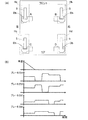
図6(A)は四輪それぞれにブレーキ装置Dbを搭載した例を示す図であり、図6(B)は、図6(A)の四輪自動車の制動時における、車速およびブレーキ力A〜Dの動作を示す図である。なお、この四輪自動車の操縦者によって要求されるブレーキ力が時間経過に沿って一定である場合を示している。 FIG. 6A is a diagram showing an example in which the brake device Db is mounted on each of the four wheels, and FIG. 6B shows the vehicle speed and the braking force A to when the four-wheeled vehicle in FIG. 6A is braked. It is a figure which shows operation | movement of D. In addition, the case where the braking force requested | required by the operator of this four-wheeled vehicle is constant along time passage is shown.
制動時の各ブレーキロータ5の温度Tは、ブレーキロータの初期温度T0、各ブレーキロータ5によるブレーキ力Fx、全ブレーキ力F、車両の運動エネルギ変化量ΔE、ブレーキロータ5の熱容量Cxから
T=T0+(ΔE・(Fx/F)/Cx)
により決定される。
The temperature T of each
Determined by.
また、ブレーキロータ5からブレーキアクチュエータ(またはブレーキフルード)等の温度、ブレーキロータの温度、図4(a)に示す熱伝導率の関係、ブレーキアクチュエータの熱容量から、伝わる熱量が決定される。実際には、全ての熱流のモデル化は困難であること、および厳密な温度制御までは必要としないことから、予め制動時の各ブレーキ装置Dbの温度上昇を試験等により把握しておき、熱伝導抑制手段35におけるブレーキ力を弱める順番等を予め決定しておいても良い。
Further, the amount of heat transmitted from the
図6(B)に示すように、一般にブレーキ力の強いフロント用ブレーキ装置Dbの温度上昇は、リア用ブレーキ装置Dbと比較して大きい傾向にあるため、左右のフロント用ブレーキ装置Dbから一輪ずつ熱伝導抑制手段35を実行している。
車速が概ね零となった時点から、A→B→C→Dの順に交互に熱伝導抑制手段35によりブレーキ力を弱めて熱伝導率を低下させる。このとき、全てのブレーキ装置Dbのブレーキ力の総和が等しくなるように、ブレーキ力を弱めるブレーキ装置Dbの他のブレーキ装置Dbにおけるブレーキ力を上昇させている。
As shown in FIG. 6B, the temperature increase of the front brake device Db, which generally has a strong braking force, tends to be larger than that of the rear brake device Db. The heat conduction suppression means 35 is executed.
From the time when the vehicle speed becomes substantially zero, the braking force is weakened by the heat conduction suppression means 35 alternately in the order of A → B → C → D to lower the thermal conductivity. At this time, the braking force of the other braking device Db that weakens the braking force is increased so that the sum of the braking forces of all the braking devices Db becomes equal.
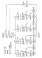
図7は、このブレーキ装置システムのブレーキ力の動作を段階的に示すフローチャートである。図3及び図6(A)と共に説明する。例えば、車両の電源を投入する条件で本処理を開始し、制動時等判定手段30は、全ブレーキ力Fが零より大か否かを判定する(ステップS1)。否との判定で(ステップS1:no)、各ブレーキ装置のブレーキ力の減圧時間を初期化(cnt=0)する(ステップS4)。次に、制動時等判定手段30は、後述のステップS3における選択枝としてid_aを図示外の記録手段に記録しておく(ステップS5)。その後本処理を終了する。 FIG. 7 is a flowchart showing stepwise the operation of the braking force of the brake device system. This will be described with reference to FIGS. 3 and 6A. For example, this process is started under the condition of turning on the power of the vehicle, and the determination means 30 during braking determines whether or not the total braking force F is greater than zero (step S1). If the determination is NO (step S1: no), the brake force depressurization time of each brake device is initialized (cnt = 0) (step S4). Next, the determination means 30 at the time of braking etc. records id_a in a recording means (not shown) as a selection branch in step S3 described later (step S5). Thereafter, this process is terminated.
全ブレーキ力Fが零より大との判定で(ステップS1:yes)、制動時等判定手段30は、車速が零または零近傍の低速か否かを判定する(ステップS2)。否との判定で(ステップS2:no)、ステップS4に移行する。車速が零または零近傍の低速であるとの判定で(ステップS2:yes)、制御装置7は、前記記録手段に記録されている選択枝を照合する(ステップS3)。
When it is determined that the total braking force F is greater than zero (step S1: yes), the braking
選択枝としてid_aが記録されているとき、熱伝導抑制手段35は、ブレーキ装置Aのブレーキ力FAを零に減圧させ(ステップS6)、ブレーキ装置B,C,Dのブレーキ力FB,FC,FDにそれぞれ減圧前のブレーキ力FAの1/3を加算する(ステップS7)。次に、熱伝導抑制手段35は、ブレーキ力FAを減圧させる設定時間tAを超えたか否かを判定する(ステップS8)。否との判定で(ステップS8:no)、ブレーキ力FAを減圧させる時間のカウンタを加算して(ステップS10)本処理を終了する。 When id_a is recorded as the selected branch, the heat conduction suppressing means 35 reduces the braking force FA of the braking device A to zero (step S6), and the braking forces F B and F of the braking devices B, C, and D. C, respectively adding the 1/3 of decompression before braking force F a to F D (step S7). Then, the heat conduction suppressing means 35 determines whether the braking force F A exceeds the set time t A for decompressing (step S8). In the determination of whether (step S8: no), and terminates the braking force F A by adding the counter time for decompressing (Step S10) the process.
設定時間tAを超えたとの判定で(ステップS8:yes)、制動時等判定手段30は、ステップS3における選択枝としてid_bを前記記録手段に記録しておく(ステップS9)。次に、制動時等判定手段30は、各ブレーキ装置のブレーキ力の減圧時間を初期化(cnt=0)し(ステップS11)、その後本処理を終了する。 Setting time determined to have exceeded the t A (step S8: yes), the brake or the like determining means 30, recording the id_b as choices in step S3 in the recording means (Step S9). Next, the determination means 30 at the time of braking or the like initializes the pressure reduction time of the braking force of each brake device (cnt = 0) (step S11), and then ends this processing.
ステップS3の選択枝としてid_bが前記記録手段に記録されているとき、熱伝導抑制手段35は、ブレーキ装置Bのブレーキ力FBを零に減圧させ(ステップS12)、ブレーキ装置A,C,Dのブレーキ力FA,FC,FDをそれぞれ減圧前のブレーキ力FBの1/3にする(ステップS13)。次に、熱伝導抑制手段35は、ブレーキ力FBを減圧させる設定時間tBを超えたか否かを判定する(ステップS14)。 When id_b is recorded in the recording means as the selected branch in step S3, the heat conduction suppressing means 35 reduces the braking force FB of the brake device B to zero (step S12), and the brake devices A, C, D The brake forces F A , F C , and F D are set to 1/3 of the brake force F B before decompression (step S13). Then, the heat conduction suppressing means 35 determines whether or not exceeded the set time t B to vacuum brake force F B (step S14).
否との判定で(ステップS14:no)、ブレーキ力FBを減圧させる時間のカウンタを加算して(ステップS16)本処理を終了する。設定時間tBを超えたとの判定で(ステップS14:yes)、制動時等判定手段30は、ステップS3における選択枝としてid_cを前記記録手段に記録しておく(ステップS15)。次に、制動時等判定手段30は、各ブレーキ装置のブレーキ力の減圧時間を初期化(cnt=0)し(ステップS17)、その後本処理を終了する。 In the determination of whether (step S14: no), and terminates the braking force F B by adding the counter time for decompressing (Step S16) the process. Setting time determined to have exceeded the t B (step S14: yes), the brake or the like determining means 30, recording the id_c as choices in step S3 in the recording means (step S15). Next, the determination means 30 at the time of braking, etc. initializes the pressure reduction time of the braking force of each brake device (cnt = 0) (step S17), and then ends this processing.
ステップS3の選択枝として前記id_cが前記記録手段に記録されているとき、熱伝導抑制手段35は、ブレーキ装置Cのブレーキ力FCを零に減圧させ(ステップS18)、ブレーキ装置A,B,Dのブレーキ力FA,FB,FDにそれぞれ減圧前のブレーキ力FCの1/3を加算する(ステップS19)。次に、熱伝導抑制手段35は、ブレーキ力FCを減圧させる設定時間tCを超えたか否かを判定する(ステップS20)。 When the id_c is recorded in the recording means as the selected branch in step S3, the heat conduction suppressing means 35 reduces the brake force FC of the brake device C to zero (step S18), and the brake devices A, B, D of the braking force F a, F B, adds 1/3 of each F D reduced pressure before the braking force F C (step S19). Then, the heat conduction suppressing means 35 determines whether the braking force F C exceeds the set time t C for decompressing (Step S20).
否との判定で(ステップS20:no)、ブレーキ力FCを減圧させる時間のカウンタを加算して(ステップS22)本処理を終了する。設定時間tCを超えたとの判定で(ステップS20:yes)、制動時等判定手段30は、ステップS3における選択枝としてid_dを前記記録手段に記録しておく(ステップS21)。その後、ブレーキ力の減圧時間を初期化(cnt=0)し(ステップS23)、その後本処理を終了する。
In the determination of whether (step S20: no), and terminates the braking force F C by adding the counter time for decompressing (Step S22) the process. When it is determined that the set time t C has been exceeded (step S20: yes), the braking
ステップS3の選択枝として前記id_dが前記記録手段に記録されているとき、ブレーキ装置Dのブレーキ力FDを零に減圧させ(ステップS24)、ブレーキ装置A,B,Cのブレーキ力FA,FB,FCにそれぞれ減圧前のブレーキ力FDの1/3を加算する(ステップS25)。次に、ブレーキ力FDを減圧させる設定時間tDを超えていないとの判定で(ステップS26:no)、ブレーキ力FDを減圧させる時間のカウンタを加算して(ステップS28)本処理を終了する。設定時間tDを超えたとの判定で(ステップS26:yes)、ステップS3における選択枝としてid_aを前記記録手段に記録し(ステップS27)、ブレーキ力の減圧時間を初期化(cnt=0)し(ステップS29)、その後本処理を終了する。 When the id_d as choices in step S3 is recorded in the recording means, it is reduced to zero braking force F D of the brake device D (step S24), and the brake device A, B, C of the braking force F A, F B, adds 1/3 of the braking force F D of the front vacuum respectively F C (step S25). Then, the braking force F D is determined in does not exceed the set time t D for decompressing (Step S26: no), the by adding the counter time for decompressing the braking force F D (step S28) the process finish. Set time t D in the determination of the exceeded (step S26: yes), the id_a as choices in step S3 is recorded in the recording means (step S27), the decompression time of the braking force initialized (cnt = 0) (Step S29), and then the process ends.
以上説明したブレーキ装置システムによれば、熱伝導抑制手段35は、前記車両が制動または停止維持中であるとの判定で、複数のブレーキ装置における一部のブレーキ装置によるブレーキ力を低下させ、前記摩擦パッド駆動手段MkつまりブレーキキャリパBkへのブレーキ摩擦熱の熱伝導率を低下させる。これにより、ブレーキロータ5(図2)と摩擦パット6(図2)との摩擦による発熱がブレーキ装置Dbの電動モータ2等に伝達することを抑制できるため、電動モータ2等の熱負荷を軽減することができる。
According to the brake device system described above, the heat conduction suppressing means 35 determines that the vehicle is being braked or stopped, and reduces the braking force by some of the brake devices in the plurality of brake devices, The thermal conductivity of the brake friction heat to the friction pad driving means Mk, that is, the brake caliper Bk is lowered. As a result, heat generated by friction between the brake rotor 5 (FIG. 2) and the friction pad 6 (FIG. 2) can be prevented from being transmitted to the
熱伝導抑制手段35は、一部のブレーキ装置によるブレーキ力の低下を、その他のブレーキ装置により補完し、全てのブレーキ装置によるブレーキ力の総和を一定に保つ機能を有する。このように一部のブレーキ装置によるブレーキ力を低下させた場合であっても、全てのブレーキ装置によるブレーキ力の総和を一定に保つことで、制動距離が不所望に長くなることを防止することができる。 The heat conduction suppression means 35 has a function of supplementing a decrease in brake force by some brake devices with other brake devices and keeping the total sum of brake forces by all brake devices constant. Even when the braking force of some braking devices is reduced in this way, the braking distance is prevented from becoming undesirably long by keeping the total braking force of all the braking devices constant. Can do.
他の実施形態について説明する。
図3の点線に示すように、各ブレーキ装置のブレーキロータまたは摩擦パッドの温度を推定する温度推定手段37をそれぞれ設け、制御装置7は、制動時等判定手段30による判定結果が車両が零または零近傍との判定と共にいずれかの温度推定手段37で推定される温度が閾値以上のとき、熱伝導抑制手段35を実行させても良い。温度測定手段37として例えばサーミスタ等を適用可能である。制動時の各ブレーキ装置の温度上昇を試験やシミュレーション等により把握しておき、この把握した結果から前記閾値を設定し得る。この場合、各ブレーキ装置のブレーキロータ5または摩擦パッド6の温度に基づいて、ブレーキ力の抑制制御を木目細かく行うことができる。サーミスタ等はブレーキキャリパBkに設けている
Another embodiment will be described.
As shown by the dotted line in FIG. 3, temperature estimation means 37 for estimating the temperature of the brake rotor or friction pad of each brake device is provided, and the
車両が、この車両に作用する重力と直交する平面上における重心点周りの4象限のそれぞれに1つ以上のブレーキ装置を備える構成において、制御装置7は、熱伝導抑制手段35を実行するとき、ブレーキ装置の動作に起因して発生する前記車両の旋回モーメントが定められた値以下となるよう各ブレーキ装置のブレーキ力を設定しても良い。この場合、車両走行中において、ブレーキ装置の動作に起因する車両の旋回モーメントを極力抑えて車両挙動の安定化を図ることができる。
In the configuration in which the vehicle includes one or more brake devices in each of the four quadrants around the center of gravity on a plane orthogonal to the gravity acting on the vehicle, when the
ブレーキ装置システムは、電動式に限定されるものではなく、例えば、マスタシリンダの油圧を各輪に配管を通じて印加する油圧ブレーキシステム等において、ABSアクチュエータのようなバルブやポンプからなる液圧制御アクチュエータであっても良い。 The brake device system is not limited to an electric type. For example, in a hydraulic brake system that applies the hydraulic pressure of a master cylinder to each wheel through a pipe, a hydraulic control actuator including a valve and a pump such as an ABS actuator is used. There may be.
前述の実施形態では、ブレーキ力を零近傍まで弱める例を示しているが、例えば、ベースのブレーキ装置のブレーキ力が大きく他のブレーキ装置の最大ブレーキ力を超過する可能性のある場合等においては、状況に応じてブレーキ力を弱める量を変動させても良い。
また、弱めたブレーキ力の分を3等分して他のブレーキ力を上昇させる例を示しているが、例えば、一般に最大ブレーキ力の大きいフロントブレーキ装置を優先して使用する、あるいは逆に、一般に温度上昇が小さいであろうリアブレーキ装置を優先して使用する等、他のブレーキ装置におけるブレーキ力増加量が異なる仕様としても良い。
In the above-described embodiment, an example in which the braking force is weakened to near zero is shown. However, for example, in a case where the braking force of the base braking device is large and may exceed the maximum braking force of other braking devices. Depending on the situation, the amount of weakening the braking force may be varied.
Moreover, although the example which raises the other brake force by dividing the part of the weak brake force into 3 equal parts is shown, for example, generally, the front brake device with the largest maximum brake force is used preferentially, or conversely, In general, the rear brake device, which is likely to have a small temperature rise, may be used preferentially. For example, the brake force increase amount in other brake devices may be different.
2…電動モータ
4…直動機構
5…ブレーキロータ
6…摩擦パッド
7…制御装置
30…制動時等判定手段
35…熱伝導抑制手段
37…温度推定手段
Mk…摩擦パッド駆動手段
DESCRIPTION OF
Claims (6)
前記制御装置に、
各ブレーキ装置の前記ブレーキロータに前記摩擦パッドを接触させ前記車両が制動または停止維持中か否かを判定する制動時等判定手段と、
この制動時等判定手段により前記車両が制動時または停止維持中であると判定したとき、前記複数のブレーキ装置における一部のブレーキ装置によるブレーキ力を低下させ、前記摩擦パッド駆動手段へのブレーキ摩擦熱の熱伝導率を低下させる熱伝導抑制手段と、
を設けたことを特徴とするブレーキ装置システム。 A brake rotor, a friction pad that makes contact with the brake rotor and generates a braking force, friction pad drive means that makes the friction pad contact the brake rotor, and a control device that controls the brake force by the friction pad drive means, In a brake system provided with a plurality of brake devices provided with a vehicle,
In the control device,
A determination means for braking and the like for determining whether the vehicle is braking or maintaining a stop by bringing the friction pad into contact with the brake rotor of each brake device;
When it is determined that the vehicle is braking or maintaining a stop by the determining means during braking, etc., the braking force by some brake devices in the plurality of brake devices is reduced, and the brake friction to the friction pad driving means is reduced. Thermal conduction suppressing means for reducing thermal conductivity of heat;
A brake device system characterized by comprising:
Priority Applications (5)
| Application Number | Priority Date | Filing Date | Title |
|---|---|---|---|
| JP2014180963A JP6404041B2 (en) | 2014-09-05 | 2014-09-05 | Brake system |
| CN201580047068.8A CN106660531B (en) | 2014-09-05 | 2015-08-28 | Braking device |
| PCT/JP2015/074360 WO2016035690A1 (en) | 2014-09-05 | 2015-08-28 | Brake device system |
| EP15837260.7A EP3190016B1 (en) | 2014-09-05 | 2015-08-28 | Brake device system |
| US15/445,124 US10343662B2 (en) | 2014-09-05 | 2017-02-28 | Brake device system |
Applications Claiming Priority (1)
| Application Number | Priority Date | Filing Date | Title |
|---|---|---|---|
| JP2014180963A JP6404041B2 (en) | 2014-09-05 | 2014-09-05 | Brake system |
Publications (2)
| Publication Number | Publication Date |
|---|---|
| JP2016055657A true JP2016055657A (en) | 2016-04-21 |
| JP6404041B2 JP6404041B2 (en) | 2018-10-10 |
Family
ID=55439753
Family Applications (1)
| Application Number | Title | Priority Date | Filing Date |
|---|---|---|---|
| JP2014180963A Active JP6404041B2 (en) | 2014-09-05 | 2014-09-05 | Brake system |
Country Status (5)
| Country | Link |
|---|---|
| US (1) | US10343662B2 (en) |
| EP (1) | EP3190016B1 (en) |
| JP (1) | JP6404041B2 (en) |
| CN (1) | CN106660531B (en) |
| WO (1) | WO2016035690A1 (en) |
Cited By (1)
| Publication number | Priority date | Publication date | Assignee | Title |
|---|---|---|---|---|
| DE112021004269T5 (en) | 2020-10-20 | 2023-10-12 | Fanuc Corporation | Parameter setting device for setting a parameter of an electric motor model |
Families Citing this family (6)
| Publication number | Priority date | Publication date | Assignee | Title |
|---|---|---|---|---|
| US20170045105A1 (en) * | 2015-08-04 | 2017-02-16 | Persimmon Technologies, Corp. | Electric Brake Caliper |
| JP6414114B2 (en) * | 2016-03-24 | 2018-10-31 | トヨタ自動車株式会社 | Electric brake caliper |
| JP2018144576A (en) * | 2017-03-03 | 2018-09-20 | Ntn株式会社 | Vehicle control device |
| US10457263B2 (en) * | 2017-07-24 | 2019-10-29 | Bendix Commercial Vehicle Systems, Llc | Brake adjustment detection using WSS based thermal measurement |
| EP3587202B1 (en) * | 2018-06-29 | 2023-04-05 | Volvo Car Corporation | System and method for determinig water content in brake fluid |
| AT523549A1 (en) * | 2020-03-13 | 2021-09-15 | Greenbrakes Gmbh | ELECTROMECHANICAL BRAKING SYSTEM |
Citations (7)
| Publication number | Priority date | Publication date | Assignee | Title |
|---|---|---|---|---|
| JPS5857526A (en) * | 1981-09-30 | 1983-04-05 | Nissin Kogyo Kk | Disc brake device |
| JPS62146027U (en) * | 1986-03-08 | 1987-09-14 | ||
| JPH08105472A (en) * | 1994-10-07 | 1996-04-23 | Hosei Brake Kogyo Kk | Drum brake with automatic shoe gap adjusting mechanism |
| JP2001080495A (en) * | 1999-09-14 | 2001-03-27 | Nissan Motor Co Ltd | Electric brake system |
| JP3380315B2 (en) * | 1993-02-17 | 2003-02-24 | マツダ株式会社 | Vehicle control device with differential limiting device and anti-skid brake |
| JP2003254364A (en) * | 2002-02-28 | 2003-09-10 | Nissin Kogyo Co Ltd | Electric disc brake |
| JP2006194356A (en) * | 2005-01-13 | 2006-07-27 | Ntn Corp | Electric linear actuator and electric brake device |
Family Cites Families (12)
| Publication number | Priority date | Publication date | Assignee | Title |
|---|---|---|---|---|
| JPS62146027A (en) | 1985-12-20 | 1987-06-30 | Matsushita Electric Ind Co Ltd | Optical output controller |
| JPH0264408A (en) * | 1988-08-31 | 1990-03-05 | Asahi Chem Ind Co Ltd | Detecting method for magnetic signal by magnetism detecting sensor |
| DE19500834C2 (en) * | 1995-01-13 | 2000-04-27 | Continental Ag | Method and device for minimizing the braking energy requirement in an electric braking system |
| JP3893753B2 (en) * | 1997-12-16 | 2007-03-14 | トヨタ自動車株式会社 | Electric brake device |
| JP3960740B2 (en) * | 2000-07-31 | 2007-08-15 | トヨタ自動車株式会社 | Brake control device for vehicle |
| DE10164719C1 (en) * | 2001-02-12 | 2003-05-28 | Knorr Bremse Systeme | Method of a method for energizing an electromechanical brake actuator of a vehicle brake depending on the brake requirement |
| CN2782496Y (en) * | 2005-03-09 | 2006-05-24 | 年纪存 | Overheat failure warning device for brake system of car |
| CN101400919A (en) * | 2006-02-07 | 2009-04-01 | 威廉·爱德华·芬纳 | Braking systems with cooling |
| FR2965873B1 (en) * | 2010-10-06 | 2012-11-30 | Peugeot Citroen Automobiles Sa | METHOD AND DEVICE FOR DETECTION OF LOCAL TRANSIENT OVERHEAT IN A COMPONENT OF A BRAKING SYSTEM |
| JP5624531B2 (en) * | 2011-09-29 | 2014-11-12 | 株式会社アドヴィックス | Brake control device for vehicle |
| CN103072568B (en) * | 2011-10-26 | 2015-08-26 | 现代摩比斯株式会社 | The over temperature warning system of vehicle disk and control method thereof |
| JP5864504B2 (en) * | 2013-10-04 | 2016-02-17 | 本田技研工業株式会社 | Vehicle braking system |
-
2014
- 2014-09-05 JP JP2014180963A patent/JP6404041B2/en active Active
-
2015
- 2015-08-28 EP EP15837260.7A patent/EP3190016B1/en active Active
- 2015-08-28 CN CN201580047068.8A patent/CN106660531B/en active Active
- 2015-08-28 WO PCT/JP2015/074360 patent/WO2016035690A1/en active Application Filing
-
2017
- 2017-02-28 US US15/445,124 patent/US10343662B2/en active Active
Patent Citations (7)
| Publication number | Priority date | Publication date | Assignee | Title |
|---|---|---|---|---|
| JPS5857526A (en) * | 1981-09-30 | 1983-04-05 | Nissin Kogyo Kk | Disc brake device |
| JPS62146027U (en) * | 1986-03-08 | 1987-09-14 | ||
| JP3380315B2 (en) * | 1993-02-17 | 2003-02-24 | マツダ株式会社 | Vehicle control device with differential limiting device and anti-skid brake |
| JPH08105472A (en) * | 1994-10-07 | 1996-04-23 | Hosei Brake Kogyo Kk | Drum brake with automatic shoe gap adjusting mechanism |
| JP2001080495A (en) * | 1999-09-14 | 2001-03-27 | Nissan Motor Co Ltd | Electric brake system |
| JP2003254364A (en) * | 2002-02-28 | 2003-09-10 | Nissin Kogyo Co Ltd | Electric disc brake |
| JP2006194356A (en) * | 2005-01-13 | 2006-07-27 | Ntn Corp | Electric linear actuator and electric brake device |
Cited By (1)
| Publication number | Priority date | Publication date | Assignee | Title |
|---|---|---|---|---|
| DE112021004269T5 (en) | 2020-10-20 | 2023-10-12 | Fanuc Corporation | Parameter setting device for setting a parameter of an electric motor model |
Also Published As
| Publication number | Publication date |
|---|---|
| CN106660531A (en) | 2017-05-10 |
| US10343662B2 (en) | 2019-07-09 |
| JP6404041B2 (en) | 2018-10-10 |
| CN106660531B (en) | 2019-07-12 |
| EP3190016B1 (en) | 2020-04-29 |
| EP3190016A1 (en) | 2017-07-12 |
| EP3190016A4 (en) | 2018-05-30 |
| WO2016035690A1 (en) | 2016-03-10 |
| US20170166178A1 (en) | 2017-06-15 |
Similar Documents
| Publication | Publication Date | Title |
|---|---|---|
| JP6404041B2 (en) | Brake system | |
| US10113601B2 (en) | Electric brake device | |
| EP2907709B1 (en) | Electric-powered parking brake device | |
| CN110053597B (en) | Electric brake system | |
| JP6275979B2 (en) | Electric brake device | |
| EP3042814B1 (en) | Electric brake device | |
| JP6336273B2 (en) | Brake device for vehicle | |
| JP2013173525A (en) | Method for providing clamping force applied by parking brake | |
| JP6397694B2 (en) | Brake device | |
| JP2008057642A (en) | Electric-brake control system and its control method | |
| JP2017094787A (en) | Brake device | |
| JP6632867B2 (en) | Brake equipment | |
| JP6258053B2 (en) | Electric brake device | |
| JP2009067264A (en) | Electric parking brake system | |
| JP6651360B2 (en) | Brake equipment | |
| JP2017159782A (en) | Direct acting actuator | |
| JP6242641B2 (en) | Electric brake system | |
| JP2018118735A (en) | Electric brake device system |
Legal Events
| Date | Code | Title | Description |
|---|---|---|---|
| A621 | Written request for application examination |
Free format text: JAPANESE INTERMEDIATE CODE: A621 Effective date: 20170829 |
|
| A131 | Notification of reasons for refusal |
Free format text: JAPANESE INTERMEDIATE CODE: A131 Effective date: 20180515 |
|
| A521 | Request for written amendment filed |
Free format text: JAPANESE INTERMEDIATE CODE: A523 Effective date: 20180713 |
|
| TRDD | Decision of grant or rejection written | ||
| A01 | Written decision to grant a patent or to grant a registration (utility model) |
Free format text: JAPANESE INTERMEDIATE CODE: A01 Effective date: 20180828 |
|
| A61 | First payment of annual fees (during grant procedure) |
Free format text: JAPANESE INTERMEDIATE CODE: A61 Effective date: 20180912 |
|
| R150 | Certificate of patent or registration of utility model |
Ref document number: 6404041 Country of ref document: JP Free format text: JAPANESE INTERMEDIATE CODE: R150 |
|
| R250 | Receipt of annual fees |
Free format text: JAPANESE INTERMEDIATE CODE: R250 |
|
| R250 | Receipt of annual fees |
Free format text: JAPANESE INTERMEDIATE CODE: R250 |
|
| R250 | Receipt of annual fees |
Free format text: JAPANESE INTERMEDIATE CODE: R250 |
|
| R250 | Receipt of annual fees |
Free format text: JAPANESE INTERMEDIATE CODE: R250 |