JP2016049309A - Game machine - Google Patents
Game machine Download PDFInfo
- Publication number
- JP2016049309A JP2016049309A JP2014176683A JP2014176683A JP2016049309A JP 2016049309 A JP2016049309 A JP 2016049309A JP 2014176683 A JP2014176683 A JP 2014176683A JP 2014176683 A JP2014176683 A JP 2014176683A JP 2016049309 A JP2016049309 A JP 2016049309A
- Authority
- JP
- Japan
- Prior art keywords
- accessory
- symbol
- value
- mpu
- data
- Prior art date
- Legal status (The legal status is an assumption and is not a legal conclusion. Google has not performed a legal analysis and makes no representation as to the accuracy of the status listed.)
- Pending
Links
Images


Abstract
Description
本発明は、パチンコ機に代表される遊技機に関するものである。 The present invention relates to a gaming machine represented by a pachinko machine.
パチンコ機等の遊技機において、発光動作が行われる発光部材や、モータ等で可変される可変部材等の演出用部材を構成に含むものがある。かかる遊技機の中には、複数の演出用部材を作動させることによって、多種多様な演出動作を実行することができるものがある。 Some gaming machines such as pachinko machines include a light-emitting member that performs a light-emitting operation and a production member such as a variable member that is variable by a motor or the like. Some of these gaming machines can execute a wide variety of performance operations by operating a plurality of performance members.
しかしながら、上述した従来の遊技機では、演出用部材の数を増加させた場合に、消費電力が増大してしまう虞があった。 However, in the conventional gaming machine described above, there is a concern that the power consumption increases when the number of effects members is increased.
本発明は、上記例示した問題点を解決するためになされたものであり、消費電力が増大してしまうことを抑制できる遊技機を提供することを目的とする。 The present invention has been made in order to solve the above-described problems, and an object thereof is to provide a gaming machine that can suppress an increase in power consumption.
この目的を達成するために請求項1記載の遊技機は、複数の作動手段と、その複数の作動手段を作動制御データに基づいて作動制御する作動制御手段と、前記複数の作動手段のうち対応する作動手段に対して前記作動制御データを設定する作動制御データ設定手段とを備え、前記作動制御データ設定手段は、前記作動手段において、第1作動状態とその第1作動状態よりも消費電力の低い第2作動状態とを少なくとも含む複数の状態が第1作動パターンで制御される第1作動制御データと、第3作動状態とその第3作動状態よりも消費電力の低い第4作動状態とを少なくとも含む複数の状態が第2作動パターンで制御される第2作動制御データとを少なくとも設定するものであり、前記作動制御データ設定手段は、前記複数の作動手段に対して前記第1作動制御データと、前記第2作動制御データとを設定する場合に、前記第1作動パターンにおいて行われる前記第1作動状態と、前記第2作動パターンにおいて行われる前記第3作動状態とが重複しない期間が存在するように設定する。
In order to achieve this object, the gaming machine according to
請求項2記載の遊技機は、請求項1記載の遊技機において、前記作動制御データ設定手段は、前記複数の作動手段に対して前記第1作動制御データと、前記第2作動制御データとを設定する場合に、前記第1作動パターンにおいて行われる少なくとも1の前記第1作動状態と、前記第2作動パターンにおいて行われる前記第3作動状態とが重複して行われないように設定するものである。
The gaming machine according to
請求項3記載の遊技機は、請求項2に記載の遊技機において、表示情報を表示する表示手段を備え、前記作動制御手段は、前記表示手段に設けられているバックライトを前記作動制御データに基づいて点灯制御するバックライト制御手段と、電飾部材の光源を前記作動制御データに基づいて点灯制御する電飾制御手段とを備え、前記作動制御データ設定手段は、前記表示手段に設けられているバックライトに対して前記第1作動制御データを設定するバックライト設定手段と、電飾部材の光源に対して前記第2作動制御データを設定する電飾設定手段とを備える。
A gaming machine according to
請求項1記載の遊技機によれば、複数の作動手段が作動制御データに基づいて作動制御手段により作動制御される。複数の作動手段のうち対応する作動手段に対して作動制御データ設定手段により作動制御データが設定される。作動手段において、第1作動状態とその第1作動状態よりも消費電力の低い第2作動状態とを少なくとも含む複数の状態が第1作動パターンで制御される第1作動制御データと、第3作動状態とその第3作動状態よりも消費電力の低い第4作動状態とが第2作動パターンで制御される第2作動制御データとが作動制御データ設定手段により少なくとも設定される。複数の作動手段に対して第1作動制御データと、第2制御データとが作動制御データ設定手段によって設定される場合は、第1作動パターンにおいて行われる第1作動状態と、第2作動パターンにおいて行われる第3作動状態とが重複して行われない期間が存在するように作動制御データ設定手段により設定される。 According to the gaming machine of the first aspect, the operation of the plurality of operation means is controlled by the operation control means based on the operation control data. The operation control data is set by the operation control data setting unit for the corresponding operation unit among the plurality of operation units. In the operation means, a first operation control data in which a plurality of states including at least a first operation state and a second operation state with lower power consumption than the first operation state are controlled by the first operation pattern, and a third operation The operation control data setting means sets at least the second operation control data in which the state and the fourth operation state whose power consumption is lower than that of the third operation state are controlled by the second operation pattern. When the first operation control data and the second control data are set for the plurality of operation means by the operation control data setting means, the first operation state performed in the first operation pattern and the second operation pattern It is set by the operation control data setting means so that there is a period in which the third operation state to be performed does not overlap.
これにより、可変手段が第1作動状態と第3作動状態とが重複して行われない期間において、消費電力を抑制することができる。よって、各作動手段において消費電力が高い作動状態となる期間が重なってしまい、消費電力が増大してしまうことを抑制することができるという効果がある。 As a result, the power consumption can be suppressed during the period when the variable means does not overlap the first operating state and the third operating state. Therefore, there is an effect that it is possible to suppress an increase in power consumption due to overlapping of periods during which the power consumption is high in each operation means.
請求項2記載の遊技機によれば、請求項1記載の遊技機の奏する効果に加え、次の効果を奏する。即ち、複数の作動手段に対して第1作動制御データと、第2作動制御データとが作動制御データ設定手段によって設定される場合に、第1作動パターンにおいて行われる少なくとも1の作動状態と、第2作動パターンにおいて行われる第3作動状態とが重複して行われないように作動制御データ設定手段により設定される。 According to the gaming machine of the second aspect, in addition to the effect of the gaming machine of the first aspect, the following effect can be obtained. That is, when the first operation control data and the second operation control data are set by the operation control data setting means for the plurality of operation means, at least one operation state performed in the first operation pattern, The operation control data setting means sets the third operation state performed in the two operation patterns so as not to overlap.
これにより、作動手段が消費電力の高い作動状態で作動制御される期間を分散させることができるので、作動手段により消費される消費電力が増大してしまうことを抑制することができるという効果がある。 As a result, it is possible to disperse the period during which the operating means is controlled to operate in an operating state with high power consumption, so that it is possible to suppress an increase in power consumption consumed by the operating means. .
請求項3記載の遊技機によれば、請求項2に記載の遊技機の奏する効果に加え、次の効果を奏する。即ち、表示情報が表示手段に表示される。作動制御手段において、表示手段に設けられているバックライトが作動制御データに基づいてバックライト制御手段により点灯制御される。また、電飾部材の光源が作動制御データに基づいて電飾制御手段により点灯制御される。 According to the gaming machine of the third aspect, in addition to the effect produced by the gaming machine according to the second aspect, the following effect is produced. That is, display information is displayed on the display means. In the operation control means, lighting of the backlight provided in the display means is controlled by the backlight control means based on the operation control data. In addition, the lighting of the light source of the electric decoration member is controlled by the electric decoration control means based on the operation control data.
これにより、バックライトと電飾部材の光源とで、点灯期間が重ならないように点灯させる期間を設けることができる。よって、当該期間において、点灯期間が重複することにより、その重複した期間中に消費電力が増大してしまうことを抑制することができるという効果がある。 Thereby, the period which makes it light so that a lighting period may not overlap with the light source of a backlight and an electrical decoration member can be provided. Therefore, there is an effect that it is possible to suppress an increase in power consumption during the overlapping period due to overlapping of the lighting periods in the period.
<第1実施形態>
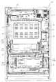
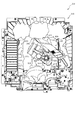
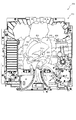
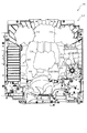
以下、本発明の第1実施形態について、添付図面を参照して説明する。図1は、第1実施形態におけるパチンコ機10の正面図であり、図2はパチンコ機10の遊技盤13の正面図であり、図3はパチンコ機10の背面図である。
<First Embodiment>
Hereinafter, a first embodiment of the present invention will be described with reference to the accompanying drawings. 1 is a front view of a
パチンコ機10は、図1に示すように、略矩形状に組み合わせた木枠により外殻が形成される外枠11と、その外枠11と略同一の外形形状に形成され外枠11に対して開閉可能に支持された内枠12とを備えている。外枠11には、内枠12を支持するために正面視(図1参照)左側の上下2カ所に金属製のヒンジ18が取り付けられ、そのヒンジ18が設けられた側を開閉の軸として内枠12が正面手前側へ開閉可能に支持されている。
As shown in FIG. 1, the
内枠12には、多数の釘や入賞口63,64等を有する遊技盤13(図2参照)が裏面側から着脱可能に装着される。この遊技盤13の前面を球が流下することにより弾球遊技が行われる。なお、内枠12には、球を遊技盤13の前面領域に発射する球発射ユニット112a(図14参照)やその球発射ユニット112aから発射された球を遊技盤13の前面領域まで誘導する発射レール(図示せず)等が取り付けられている。
A game board 13 (see FIG. 2) having a large number of nails, winning
内枠12の前面側には、その前面上側を覆う前面枠14と、その下側を覆う下皿ユニット15とが設けられている。前面枠14及び下皿ユニット15を支持するために正面視(図1参照)左側の上下2カ所に金属製のヒンジ19が取り付けられ、そのヒンジ19が設けられた側を開閉の軸として前面枠14及び下皿ユニット15が正面手前側へ開閉可能に支持されている。なお、内枠12の施錠と前面枠14の施錠とは、シリンダ錠20の鍵穴21に専用の鍵を差し込んで所定の操作を行うことでそれぞれ解除される。
On the front side of the
前面枠14は、装飾用の樹脂部品や電気部品等を組み付けたものであり、その略中央部には略楕円形状に開口形成された窓部14cが設けられている。前面枠14の裏面側には2枚の板ガラスを有するガラスユニット16が配設され、そのガラスユニット16を介して遊技盤13の前面がパチンコ機10の正面側に視認可能となっている。
The
前面枠14には、球を貯留する上皿17が前方へ張り出して上面を開放した略箱状に形成されており、この上皿17に賞球や貸出球などが排出される。上皿17の底面は正面視(図1参照)右側に下降傾斜して形成され、その傾斜により上皿17に投入された球が球発射ユニット112aへと案内される。また、上皿17の上面には、枠ボタン228が設けられている。この枠ボタン228は、例えば、後述する第3図柄表示装置81(図2参照)で表示される演出のステージを変更したり、スーパーリーチの演出内容を変更したりする場合などに、遊技者により操作される。
On the
ステージとは、第3図柄表示装置81に表示される各種演出に統一性を持たせた演出モードのことで、本パチンコ機10では「街中ステージ」,「空ステージ」,「島ステージ」の3つのステージが設けられている。そして、後述する第1入球口64への入球(始動入賞)に伴って行われる変動演出やリーチ演出などの各種演出は、それぞれのステージに与えられたテーマに合わせて行われるように設計されている。ステージの変更は、変動演出が行われていない期間や高速変動中に遊技者によって枠ボタン228が操作された場合に行われ、枠ボタン228が操作される度に「街中ステージ」→「空ステージ」→「島ステージ」→「街中ステージ」→・・・の順で繰り返し変更される。また、電源投入後の直後は、初期ステージとして「街中ステージ」が設定される。
The stage is an effect mode in which the various effects displayed on the third
一方、第3図柄表示装置81には、ノーマルリーチ演出が開始された場合に、ノーマルリーチからスーパーリーチに発展させるときは、ノーマルリーチ中にスーパーリーチの演出態様の選択画面が表示されるように構成されており、その選択画面が表示されている間に、枠ボタン228が遊技者に操作されると、スーパーリーチ時の演出内容が変更される。
On the other hand, the 3rd
前面枠14には、その周囲(例えばコーナー部分)に各種ランプ等の発光手段が設けられている。これら発光手段は、大当たり時や所定のリーチ時等における遊技状態の変化に応じて、点灯又は点滅することにより発光態様が変更制御され、遊技中の演出効果を高める役割を果たす。窓部14cの周縁には、LED等の発光手段を内蔵した電飾部29〜33が設けられている。パチンコ機10においては、これら電飾部29〜33が大当たりランプ等の演出ランプとして機能し、大当たり時やリーチ演出時等には内蔵するLEDの点灯や点滅によって各電飾部29〜33が点灯または点滅して、大当たり中である旨、或いは大当たり一歩手前のリーチ中である旨が報知される。また、前面枠14の正面視(図1参照)左上部には、LED等の発光手段が内蔵され賞球の払い出し中とエラー発生時とを表示可能な表示ランプ34が設けられている。
The
また、右側の電飾部32下側には、前面枠14の裏面側を視認できるように裏面側より透明樹脂を取り付けて小窓35が形成され、遊技盤13前面の貼着スペースK1(図2参照)に貼付される証紙等はパチンコ機10の前面から視認可能とされている。また、パチンコ機10においては、より煌びやかさを醸し出すために、電飾部29〜33の周りの領域にクロムメッキを施したABS樹脂製のメッキ部材36が取り付けられている。
In addition, a
窓部14cの下方には、貸球操作部40が配設されている。貸球操作部40には、度数表示部41と、球貸しボタン42と、返却ボタン43とが設けられている。パチンコ機10の側方に配置されるカードユニット(球貸しユニット)(図示せず)に紙幣やカード等を投入した状態で貸球操作部40が操作されると、その操作に応じて球の貸出が行われる。具体的には、度数表示部41はカード等の残額情報が表示される領域であり、内蔵されたLEDが点灯して残額情報として残額が数字で表示される。球貸しボタン42は、カード等(記録媒体)に記録された情報に基づいて貸出球を得るために操作されるものであり、カード等に残額が存在する限りにおいて貸出球が上皿17に供給される。返却ボタン43は、カードユニットに挿入されたカード等の返却を求める際に操作される。なお、カードユニットを介さずに球貸し装置等から上皿17に球が直接貸し出されるパチンコ機、いわゆる現金機では貸球操作部40が不要となるが、この場合には、貸球操作部40の設置部分に飾りシール等を付加して部品構成は共通のものとしても良い。カードユニットを用いたパチンコ機と現金機との共通化を図ることができる。
A ball
上皿17の下側に位置する下皿ユニット15には、その中央部に上皿17に貯留しきれなかった球を貯留するための下皿50が上面を開放した略箱状に形成されている。下皿50の右側には、球を遊技盤13の前面へ打ち込むために遊技者によって操作される操作ハンドル51が配設され、かかる操作ハンドル51の内部には球発射ユニット112aの駆動を許可するためのタッチセンサ51aと、押下操作している期間中には球の発射を停止する押しボタン式の打ち止めスイッチ51bと、操作ハンドル51の回動操作量を電気抵抗の変化により検出する可変抵抗器(図示せず)とが内蔵されている。操作ハンドル51が遊技者によって右回りに回転操作されると、タッチセンサ51aがオンされると共に可変抵抗器の抵抗値が操作量に対応して変化し、操作ハンドル51の回動操作量に応じて変化する可変抵抗器の抵抗値に対応した強さで球が発射され、これにより遊技者の操作に対応した飛び量で遊技盤13の前面へ球が打ち込まれる。また、操作ハンドル51が遊技者により操作されていない状態においては、タッチセンサ51aおよび打ち止めスイッチ51bがオフとなっている。
In the
下皿50の正面下方部には、下皿50に貯留された球を下方へ排出する際に操作するための球抜きレバー52が設けられている。この球抜きレバー52は、常時、右方向に付勢されており、その付勢に抗して左方向へスライドさせることにより、下皿50の底面に形成された底面口が開口して、その底面口から球が自然落下して排出される。かかる球抜きレバー52の操作は、通常、下皿50の下方に下皿50から排出された球を受け取る箱(一般に「千両箱」と称される)を置いた状態で行われる。下皿50の右方には、上述したように操作ハンドル51が配設され、下皿50の左方には灰皿53が取り付けられている。
In the lower part of the front of the
図2に示すように、遊技盤13は、正面視略正方形状に切削加工したベース板60に、球案内用の多数の釘(図示せず)や風車(可動部材310を図示し、その他は図示せず)の他、レール61,62、一般入賞口63、第1入球口64、第2入球口640、第一可変入賞装置65、第2可変入賞装置(図示せず)、普通入球口67、可変表示装置ユニット80等を組み付けて構成され、その周縁部が内枠12(図1参照)の裏面側に取り付けられる。ベース板60は光透過性の樹脂材料からなり、その正面側からベース板60の後面側に配設された各種構造体を遊技者に視認させることが可能に形成される。一般入賞口63、第1入球口64、第2入球口640、第1可変入賞装置65、第2可変入賞装置(図示せず)、可変表示装置ユニット80は、ルータ加工によってベース板60に形成された貫通穴に配設され、遊技盤13の正面側からタッピングネジ等により固定されている。
As shown in FIG. 2, the
遊技盤13の正面中央部分は、正面枠14の窓部14c(図1参照)を通じて内枠12の正面側から視認することができる。以下に、主に図2を参照して、遊技盤13の構成について説明する。
The front center portion of the
遊技盤13の正面には、帯状の金属板を略円弧状に屈曲加工して形成した外レール62が植立され、その外レール62の内側位置には外レール62と同様に帯状の金属板で形成した円弧状の内レール61が植立される。この内レール61と外レール62とにより遊技盤13の正面外周が囲まれ、遊技盤13とガラスユニット16(図1参照)とにより前後が囲まれることにより、遊技盤13の正面には、球の挙動により遊技が行われる遊技領域が形成される。遊技領域は、遊技盤13の正面であって2本のレール61,62とレール間を繋ぐ樹脂製の外縁部材73とにより区画して形成される領域(入賞口等が配設され、発射された球が流下する領域)である。
An
2本のレール61,62は、球発射ユニット112a(図14参照)から発射された球を遊技盤13上部へ案内するために設けられたものである。内レール61の先端部分(図2の左上部)には戻り球防止部材68が取り付けられ、一旦、遊技盤13の上部へ案内された球が再度球案内通路内に戻ってしまうといった事態が防止される。外レール62の先端部(図2の右上部)には、球の最大飛翔部分に対応する位置に返しゴム69が取り付けられ、所定以上の勢いで発射された球は、返しゴム69に当たって、勢いが減衰されつつ中央部側へ跳ね返される。
The two
遊技領域の正面視左側下部(図2の左側下部)には、発光手段である複数のLED及び7セグメント表示器を備える第1図柄表示装置37a,37bが配設されている。第1図柄表示装置37a,37bは、主制御装置110(図14参照)で行われる各制御に応じた表示がなされるものであり、主にパチンコ機10の遊技状態の表示が行われる。本実施形態では、第1図柄表示装置37a,37bは、球が、第1入球口64へ入賞したか、第2入球口640へ入賞したかに応じて使い分けられるように構成されている。具体的には、球が、第1入球口64へ入賞した場合には、第1図柄表示装置37aが作動し、一方で、球が、第2入球口640へ入賞した場合には、第1図柄表示装置37bが作動するように構成されている。
A first
また、第1図柄表示装置37a,37bは、LEDにより、パチンコ機10が確変中か時短中か通常中であるかを点灯状態により示したり、変動中であるか否かを点灯状態により示したり、停止図柄が確変大当たりに対応した図柄か普通大当たりに対応した図柄か外れ図柄であるかを点灯状態により示したり、保留球数を点灯状態により示すと共に、7セグメント表示装置により、大当たり中のラウンド数やエラー表示を行う。なお、複数のLEDは、それぞれのLEDの発光色(例えば、赤、緑、青)が異なるよう構成され、その発光色の組み合わせにより、少ないLEDでパチンコ機10の各種遊技状態を示唆することができる。
In addition, the first
なお、本パチンコ機10では、第1入球口64及び第2入球口640へ入賞があったことを契機として抽選が行われる。パチンコ機10は、その抽選において、大当たりか否かの当否判定(大当たり抽選)を行うと共に、大当たりと判定した場合はその大当たり種別の判定も行う。ここで判定される大当たり種別としては、確変大当たり(大当たりA)、時短大当たり(大当たりB)が用意されている。第1図柄表示装置37a,37bには、変動終了後の停止図柄として抽選の結果が大当たりであるか否かが示されるだけでなく、大当たりである場合はその大当たり種別に応じた図柄が示される。
In the
ここで、「確変大当たり」とは、最大ラウンド数が16ラウンドの大当たりの後に高確率状態へ移行する確変大当たりのことであり、「時短大当たり」は、最大ラウンド数が16ラウンドの大当たりの後に、低確率状態へ移行すると共に、所定の変動回数の間(例えば、100変動回数)は時短状態となる大当たりのことである。 Here, the “probable jackpot” is a probable jackpot where the maximum number of rounds shifts to a high probability state after a jackpot of 16 rounds, and the “short-time jackpot” is a jackpot of 16 rounds, While shifting to the low-probability state, during a predetermined number of fluctuations (for example, 100 fluctuations) is a jackpot that becomes a short-time state.
また、「高確率状態」とは、大当たり終了後に付加価値としてその後の大当たり確率がアップした状態、いわゆる確率変動中(確変中)の時をいい、換言すれば、特別遊技状態(大当たり)へ移行し易い遊技の状態のことである。本実施形態における高確率状態(確変中)は、後述する第2図柄の当たり確率がアップして第2入球口640へ球が入賞し易い遊技の状態を含む。「低確率状態」とは、確変中でない時をいい、大当たり確率が通常の状態、即ち、確変中よりも大当たり確率が低い状態をいう。また、「低確率状態」のうちの時短状態(時短中)とは、大当たり確率が通常の状態であると共に、普通図柄(第2図柄)の当たり確率がアップして第2入球口640へ球が入賞し易い遊技の状態のことをいう。一方、パチンコ機10が通常中とは、確変中でも時短中でもない遊技の状態(特別図柄の大当たり確率も普通図柄の当たり確率もアップしていない状態)である。
In addition, the “high probability state” means a state in which the subsequent jackpot probability has been increased as an added value after the jackpot ends, that is, when the probability is changing (probability is changing), in other words, transition to the special gaming state (jackpot). It is a game state that is easy to play. The high probability state (during probability change) in the present embodiment includes a game state in which the hit probability of the second symbol, which will be described later, is increased and the ball is likely to win the
確変中や時短中は、普通図柄の当たり確率がアップするだけではなく、第2入球口640に付随する電動役物640aが開放される時間も変更され、通常中に比して長い時間が設定される。電動役物640aが開放された状態(開放状態)にある場合は、その電動役物640aが閉鎖された状態(閉鎖状態)にある場合に比して、第2入球口640へ球が入賞しやすい状態となる。よって、確変中や時短中は、第2入球口640へ球が入賞し易い状態となり、大当たり抽選が行われる回数を増やすことができる。
During probability change and time reduction, not only the normal symbol hit probability is increased, but also the time that the
なお、確変中や時短中において、第2入球口640に付随する電動役物640aの開放時間を変更するのではなく、または、その開放時間を変更することに加えて、1回の当たりで電動役物640aが開放する回数を通常中よりも増やす変更を行うものとしてもよい。また、確変中や時短中において、第2図柄の当たり確率は変更せず、第2入球口640に付随する電動役物640aが開放される時間および1回の当たりで電動役物640aが開放する回数の少なくとも一方を変更するものとしてもよい。また、確変中や時短中において、第2入球口640に付随する電動役物640aが開放される時間や、1回の当たりで電動役物640aを開放する回数はせず、第2図柄の当たり確率だけを、通常中と比してアップするよう変更するものであってもよい。
In addition, during the probability change or in the short time, the opening time of the
遊技領域には、球が入賞することにより5個から15個の球が賞球として払い出される複数の一般入賞口63が配設されている。また、遊技領域の中央部分には、可変表示装置ユニット80が配設されている。可変表示装置ユニット80には、第1入球口64及び第2入球口640への入賞(始動入賞)をトリガとして、第1図柄表示装置37a,37bにおける変動表示と同期させながら、第3図柄の変動表示を行う液晶ディスプレイ(以下単に「表示装置」と略す)で構成された第3図柄表示装置81と、普通入球口67の球の通過をトリガとして第2図柄を変動表示するLEDで構成される第2図柄表示装置(図示せず)とが設けられている。また、可変表示装置ユニット80には、第3図柄表示装置81の外周を囲むようにして、センターフレーム86が配設されている。
The game area is provided with a plurality of general winning
第3図柄表示装置81は9インチサイズの大型の液晶ディスプレイで構成されるものであり、表示制御装置114(図14参照)によって表示内容が制御されることにより、例えば上、中及び下の3つの図柄列が表示される。各図柄列は複数の図柄(第3図柄)によって構成され、これらの第3図柄が図柄列毎に横スクロールして第3図柄表示装置81の表示画面上にて第3図柄が可変表示されるようになっている。本実施形態の第3図柄表示装置81は、主制御装置110(図14参照)の制御に伴った遊技状態の表示が第1図柄表示装置37A,37Bで行われるのに対して、その第1図柄表示装置37A,37Bの表示に応じた装飾的な表示を行うものである。なお、表示装置に代えて、例えばリール等を用いて第3図柄表示装置81を構成するようにしても良い。
The third
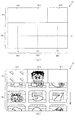
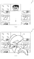
ここで、図4を参照して、第3図柄表示装置81の表示内容について説明する。図4は、第3図柄表示装置81の表示画面を説明するための図面であり、図4(a)は、表示画面の領域区分設定と有効ライン設定とを模式的に示した図であり、図4(b)は、実際の表示画面を例示した図である。
Here, with reference to FIG. 4, the display content of the 3rd
第3図柄は、「0」から「9」の数字を付した10種類の主図柄により構成されている。各主図柄は、木箱よりなる後方図柄の上に「0」から「9」の数字を付して構成され、そのうち奇数番号(1,3,5,7,9)を付した主図柄は、木箱の前面ほぼ一杯に大きな数字が付加されている。これに対し、偶数番号(0,2,4,6,8)を付した主図柄は、木箱の前面ほぼ一杯にかんな、風呂敷、ヘルメット等のキャラクタを模した付属図柄が付加されており、付属図柄の右下側に偶数の数字が緑色で小さく、且つ、付属図柄の前側に表示されるように付加されている。 The third symbol is composed of ten kinds of main symbols with numbers from “0” to “9”. Each main symbol is composed of numbers from “0” to “9” on the rear symbol consisting of a wooden box, of which the main symbols with odd numbers (1, 3, 5, 7, 9) are A large number is added to almost the front of the wooden box. On the other hand, the main symbols with even numbers (0, 2, 4, 6, 8) have attached symbols that imitate characters such as furoshiki, helmet, etc., almost full front of the wooden box, An even number is small in green on the lower right side of the attached symbol and is added so as to be displayed on the front side of the attached symbol.
また、本実施形態のパチンコ機10においては、後述する主制御装置110(図14参照)により行われる特別図柄の抽選結果が大当たりであった場合に、同一の主図柄が揃う変動表示が行われ、その変動表示が終わった後に大当たりが発生するよう構成されている。一方、特別図柄の抽選結果が外れであった場合は、同一の主図柄が揃わない変動表示が行われる。
Further, in the
例えば、特別図柄の抽選結果が「大当たりB」であれば、偶数番号である「0,2,4,6,8」が付加された主図柄が揃う変動表示が行われる。また、「大当たりA」であれば、奇数番号である「1,3,5,7,9」が付加された主図柄が揃う変動表示が行われる。一方、特別図柄の抽選結果が外れであれば、同一番号の主図柄が揃わない変動表示が行われる。 For example, if the lottery result of the special symbol is “big hit B”, the variable display in which the main symbols to which the even numbers “0, 2, 4, 6, 8” are added is arranged. Further, if “big hit A”, a variable display is performed in which main symbols to which odd numbers “1, 3, 5, 7, 9” are added are arranged. On the other hand, if the lottery result of the special symbol is off, the variable display in which the main symbols of the same number are not aligned is performed.
図4(a)に示すように、第3図柄表示装置81の表示画面は、大きくは上下に2分割され、下側の2/3が第3図柄を変動表示する主表示領域Dm、それ以外の上側の1/3が予告演出、キャラクタおよび保留球数などを表示する副表示領域Dsとなっている。
As shown in FIG. 4 (a), the display screen of the third
主表示領域Dmは、左・中・右の3つの表示領域Dm1〜Dm3に区分けされており、その3つの表示領域Dm1〜Dm3に、それぞれ3つの図柄列Z1,Z2,Z3が表示される。各図柄列Z1〜Z3には、上述した第3図柄が規定の順序で表示される。即ち、各図柄列Z1〜Z3には、数字の昇順または降順に主図柄が配列され、図柄列Z1〜Z3毎に周期性をもって上から下へとスクロールして変動表示が行われる。特に、左図柄列Z1においては主図柄の数字が降順に現れるように配列され、中図柄列Z2及び右図柄列Z3においては主図柄の数字が昇順に現れるように配列されている。 The main display area Dm is divided into three display areas Dm1 to Dm3 of left, middle, and right, and three symbol rows Z1, Z2, and Z3 are displayed in the three display areas Dm1 to Dm3, respectively. In each symbol row Z1 to Z3, the above-described third symbols are displayed in a prescribed order. That is, the main symbols are arranged in ascending or descending numbers in the symbol rows Z1 to Z3, and the symbol rows Z1 to Z3 are scrolled from the top to the bottom with periodicity to perform the variable display. In particular, the left symbol row Z1 is arranged so that the numbers of the main symbols appear in descending order, and the middle symbol row Z2 and the right symbol row Z3 are arranged so that the numbers of the main symbols appear in ascending order.
また、主表示領域Dmには、図柄列Z1〜Z3毎に上・中・下の3段に第3図柄が表示される。この主表示領域Dmの中段部が有効ラインL1として設定されており、毎回の遊技に際して、左図柄列Z1→右図柄列Z3→中図柄列Z2の順に、有効ラインL1上に第3図柄が停止表示される。その第3図柄の停止時に有効ラインL1上に大当たり図柄の組合せ(本実施形態では、同一の主図柄の組合せ)で揃えば大当たりとして大当たり動画が表示される。 In the main display area Dm, the third symbols are displayed in the upper, middle, and lower three rows for each of the symbol rows Z1 to Z3. The middle part of the main display area Dm is set as the active line L1, and in each game, the third symbol stops on the effective line L1 in the order of the left symbol row Z1, the right symbol row Z3, and the middle symbol row Z2. Is displayed. If the combination of jackpot symbols (the same main symbol combination in this embodiment) is arranged on the effective line L1 when the third symbol is stopped, a jackpot moving image is displayed as a jackpot.
一方、副表示領域Dsは、主表示領域Dmよりも上方に横長に設けられており、さらに左右方向に3つの小領域Ds1〜Ds3に等区分されている。このうち、小領域Ds1は、第1入球口64に入球された球のうち変動が未実行である球(保留球)の数である保留球数を表示する領域であり、小領域Ds2およびDs3は、予告演出画像を表示する領域である。
On the other hand, the sub display area Ds is horizontally long above the main display area Dm, and is further equally divided into three small areas Ds1 to Ds3 in the left-right direction. Among these, the small area Ds1 is an area for displaying the number of reserved balls, which is the number of spheres that have not been changed (reserved spheres) among the balls that have entered the
実際の表示画面では、図4(b)に示すように、主表示領域Dmに第3図柄の主図柄が合計9個表示される。副表示領域Dsにおいては、右の小領域Ds3に動画が表示され、通常より大当たりへ遷移し易い状態であることが遊技者に示唆される。中央の小領域Ds2では、通常は、所定のキャラクタ(本実施形態ではハチマキを付けた少年)が所定動作をし、時として所定動作とは別の特別な動作をしたり、別のキャラクタが現出する等して予告演出が行われる。 On the actual display screen, as shown in FIG. 4B, a total of nine main symbols of the third symbol are displayed in the main display area Dm. In the sub display area Ds, a moving image is displayed in the small area Ds3 on the right, and it is suggested to the player that the player is more likely to make a big hit than usual. In the central small area Ds2, a predetermined character (a boy with a bee in this embodiment) usually performs a predetermined action and sometimes performs a special action different from the predetermined action, or another character appears. The announcement effect is performed by putting out.
一方、第3図柄表示装置81(第1図柄表示装置37)にて変動表示が行われている間に球が第1入球口64へ入球した場合、その入球回数は最大4回まで保留され、その保留球数は第1図柄表示装置37により示されると共に、副表示領域Dsの小領域Ds1においても示される。小領域Ds1には、保留球数1球につき1つの保留球数図柄が表示され、その保留球数図柄の表示数に応じて、保留球数が表示される。即ち、小領域Ds1に1つの保留球数図柄が表示されている場合は、保留球数が1球であることを示し、4つの保留球数図柄が表示されている場合は、保留球数が4球であることを示す。また、小領域Ds1に保留球数図柄が表示されていない場合は、保留球数が0球である、即ち、保留球が存在しないことを示す。
On the other hand, when a ball enters the
なお、本実施形態においては、第1入球口64への入球は、最大4回まで保留されるように構成したが、最大保留球数は4回に限定されるものでなく、3回以下、又は、5回以上の回数(例えば、8回)に設定しても良い。また、小領域Ds1における保留球数図柄の表示に代えて、保留球数を第3図柄表示装置81の一部に数字で、或いは、4つに区画された領域を保留球数分だけ異なる態様(例えば、色や点灯パターン)にして表示するようにしても良い。また、第1図柄表示装置37により保留球数が示されるので、第3図柄表示装置81に保留球数を表示させないものとしてもよい。更に、可変表示装置ユニット80に、保留球数を示す保留ランプを最大保留数分の4つ設け、点灯状態の保留ランプの数に応じて、保留球数を表示するものとしてもよい。
In the present embodiment, the ball entering the
第2図柄表示装置は、球が普通入球口67を通過する毎に普通図柄(第2図柄(図示せず))としての「○」の図柄と「×」の図柄とを所定時間交互に点灯させる変動表示を行うものである。パチンコ機10では、球が普通入球口67を通過したことが検出されると、当たりか否かが抽選される。その抽選の結果、当たりであれば、第2図柄表示装置において、普通図柄(第2図柄)の変動表示後に「○」の図柄が停止表示される。また、当たりか否かの抽選結果が外れであれば、第2図柄表示装置において、普通図柄(第2図柄)の変動表示後に「×」の図柄が停止表示される。
Each time the ball passes through the
パチンコ機10は、第2図柄表示装置における変動表示が所定図柄(本実施形態においては「○」の図柄)で停止した場合に、第2入球口640に付随する電動役物640aが所定時間だけ作動状態となる(開放される)ように構成されている。
In the
普通図柄(第2図柄)の変動表示にかかる時間は、遊技状態が通常中の場合よりも、確変中または時短中の方が短くなるように設定される。これにより、確変中および時短中は、第2図柄の変動表示が短い時間で行われるので、普通図柄の抽選を通常中よりも多く行うことができる。よって、普通図柄の当たりとなる機会が増えるので、第2入球口640に付随する電動役物640aが開放状態となる機会を遊技者に多く与えることができる。従って、確変中および時短中は、第2入球口640へ球が入賞しやすい状態とすることができる。
The time required for the variable display of the normal symbol (the second symbol) is set to be shorter during the probability change or the shorter time than when the game state is normal. As a result, during the probability change and during the time reduction, since the variation display of the second symbol is performed in a short time, the lottery of the normal symbol can be performed more than during normal. Therefore, since the chance of winning the normal symbol increases, it is possible to give the player many opportunities to open the
なお、確変中または時短中において、その他の方法(例えば、普通図柄の当たりとなる確率を高める、1回の当たりに対する電動役物640aの開放時間や開放回数を増やす等)によって、確変中または時短中に球が第2入球口640へと入賞しやすい状態としている場合は、普通図柄(第2図柄)の変動表示にかかる時間を遊技状態にかかわらず一定としてもよい。一方、確変中または時短中において、普通図柄(第2図柄)の変動表示にかかる時間を通常中よりも短く設定する場合は、当たり確率を遊技状態にかかわらず一定にしてもよい。また、1回の当たりに対する電動役物640aの開放時間や開放回数を遊技状態にかかわらず一定にしてもよい。
In addition, during probability change or time reduction, other methods (for example, increasing the probability of winning a normal symbol, increasing the opening time or the number of times of opening of the
普通入球口67は、可変表示装置ユニット80の下側の領域における右方において遊技盤に組み付けられ、遊技盤に発射された球のうち、遊技盤の右方を流下する球の一部が通過可能に構成されている。球が普通入球口67を通過すると、普通図柄(第2図柄)の当たり抽選が行われる。当たり抽選の後、第2図柄表示装置にて変動表示を行い、当たり抽選の結果が当たりであれば、変動表示の停止図柄として「○」の図柄を表示し、当たり抽選の結果が外れであれば、変動表示の停止図柄として「×」の図柄を表示する。
The
第2図柄表示装置において変動表示が行われている間に球が普通入球口67を通過すると、その通過回数は最大4回まで保留され、その保留球数が上述した第1図柄表示装置37a,37bにより表示されると共に第2図柄保留ランプ(図示せず)においても点灯表示される。第2図柄保留ランプは、最大保留回数分の4つ設けられており、第3図柄表示装置81の下方に左右対称に配設されている。
When the ball passes through the
なお、第2図柄の変動表示は、本実施形態のように、第2図柄表示装置において所定の図柄(「○」の図柄と「×」の図柄)を交互に点灯表示させることにより行うものの他、第1図柄表示装置37a,37b及び第3図柄表示装置81の一部を使用して行うようにしても良い。同様に、第2図柄保留ランプの点灯を第3図柄表示装置81の一部で行うようにしても良い。また、普通入球口67の球の通過に対する最大保留球数は4回に限定されるものでなく、3回以下、又は、5回以上の回数(例えば、8回)に設定しても良い。また、普通入球口67の組み付け数は1つに限定されるものではなく、複数(例えば、2つ)であっても良い。また、普通入球口67の組み付け位置は可変表示装置ユニット80の右方に限定されるものではなく、例えば、可変表示装置ユニット80の左方でも良い。また、第1図柄表示装置37a,37bにより保留球数が示されるので、第2図柄保留ランプにより点灯表示を行わないものとしてもよい。
In addition, the variation display of the second symbol is performed by alternately lighting a predetermined symbol (the symbol “◯” and the symbol “X”) on the second symbol display device as in the present embodiment. Alternatively, a part of the first
可変表示装置ユニット80の下方には、球が入賞し得る第1入球口64が配設されている。この第1入球口64へ球が入賞すると遊技盤13の裏面側に設けられる第1入球口スイッチ(図示せず)がオンとなり、その第1入球口スイッチのオンに起因して主制御装置110(図14参照)で大当たりの抽選がなされ、その抽選結果に応じた表示が第1図柄表示装置37aで示される。
Below the
一方、第1入球口64の正面視右方には、球が入賞し得る第2入球口640が配設されている。この第2入球口640へ球が入賞すると遊技盤13の裏面側に設けられる第2入球口スイッチ(図示せず)がオンとなり、その第2入球口スイッチのオンに起因して主制御装置110(図14参照)で大当たりの抽選がなされ、その抽選結果に応じた表示が第1図柄表示装置37bで示される。
On the other hand, on the right side of the
また、第1入球口64および第2入球口640は、それぞれ、球が入賞すると5個の球が賞球として払い出される入賞口の1つにもなっている。なお、本実施形態においては、第1入球口64へ球が入賞した場合に払い出される賞球数と第2入球口640へ球が入賞した場合に払い出される賞球数とを同一としたが、第1入球口64へ球が入賞した場合に払い出される賞球数と第2入球口640へ球が入賞した場合に払い出される賞球数とを異なる数(例えば、第1入球口64へ球が入賞した場合に払い出される賞球数を3個、第2入球口640へ球が入賞した場合に払い出される賞球数を5個)としてもよい。
Each of the
第2入球口640には電動役物640aが付随している。この電動役物640aは開閉可能に構成されており、通常は電動役物640aが閉鎖状態(縮小状態)となって、球が第2入球口640へ入賞しにくい状態となっている。一方、普通入球口67への球の通過を契機として行われる第2図柄の変動表示の結果、「○」の図柄が第2図柄表示装置に表示された場合、電動役物640aが開放状態(拡大状態)となり、球が第2入球口640へ入賞しやすい状態となる。
The
上述した通り、確変中および時短中は、通常中に比べて普通図柄(第2図柄)の当たり確率が高く、且つ、普通図柄(第2図柄)の変動表示にかかる時間も短い。よって、普通図柄(第2図柄)の変動表示において「○」の図柄が表示され易くなるので、電動役物640aが開放状態(拡大状態)となる回数が増える。更に、確変中および時短中は、電動役物640aが開放される時間も、通常中より長くなる。従って、確変中および時短中は、通常中に比べて球が第2入球口640へと入賞し易くすることができる。
As described above, the probability of hitting the normal symbol (second symbol) is higher and the time required for displaying the fluctuation of the normal symbol (second symbol) is shorter during normal change and during shorter time than normal. Accordingly, since the symbol “◯” is easily displayed in the variation display of the normal symbol (second symbol), the number of times that the
ここで、第1入球口64に球が入賞した場合と第2入球口640へ球が入賞した場合とで、大当たりとなる確率は、低確率状態であっても高確率状態でも同一である。また、第1入球口64は、第2入球口640にあるような電動役物は有しておらず、球が常時入賞可能な状態となっている。
Here, the probability of winning a big hit between the case where the ball is won at the
よって、通常中においては、第2入球口640に付随する電動役物が閉鎖状態にある場合が多く、第2入球口640に入賞し難いので、電動役物のない第1入球口64へ向けて、可変表示装置ユニット80の左方を球が通過するように球を発射し(所謂「左打ち」)、第1入球口64への入賞によって大当たり抽選の機会を多く得て、大当たりとなることを狙った方が、遊技者にとって有利となる。
Therefore, during normal times, the electric accessory associated with the
一方、確変中や時短中は、普通入球口67に球を通過させることで、第2入球口640に付随する電動役物640aが開放状態となりやすく、第2入球口640に入賞しやすい状態であるので、第2入球口640へ向けて、可変表示装置80の右方を球が通過するように球を発射し(所謂「右打ち」)、普通入球口67を通過させて電動役物を開放状態にすると共に、第2入球口640への入賞によって大当たりとなることを狙った方が、遊技者にとって有利となる。
On the other hand, during the probability change or during the short time, passing the ball through the
このように、本実施形態のパチンコ機10は、パチンコ機10の遊技状態(確変中であるか、時短中であるか、通常中であるか)に応じて、遊技者に対し、球の発射の仕方を「左打ち」と「右打ち」とに変えさせることができる。よって、遊技者に対して、球の打ち方に変化をもたらすことができるので、遊技を楽しませることができる。
As described above, the
第1入球口64の下方右側には第1可変入賞装置65が配設されており、その略中央部分に横長矩形状の特定入賞口(大開放口)65aが設けられている。パチンコ機10においては、第1入球口64又は第2入球口640への入賞に起因して行われた大当たり抽選が大当たりとなると、所定時間(変動時間)が経過した後に、大当たりの停止図柄となるよう第1図柄表示装置37a又は第1図柄表示装置37bを点灯させると共に、その大当たりに対応した停止図柄を第3図柄表示装置81に表示させて、大当たりの発生が示される。その後、球が入賞し易い特別遊技状態(大当たり)に遊技状態が遷移する。この特別遊技状態として、通常時には閉鎖されている特定入賞口65aが、所定時間(例えば、30秒経過するまで、或いは、球が10個入賞するまで)開放される。
A first variable winning
この特定入賞口65aは、所定時間が経過すると閉鎖され、その閉鎖後、再度、その特定入賞口65aが所定時間開放される。この特定入賞口65aの開閉動作は、最高で例えば16回(16ラウンド)繰り返し可能にされている。この開閉動作が行われている状態が、遊技者にとって有利な特別遊技状態の一形態であり、遊技者には、遊技上の価値(遊技価値)の付与として通常時より多量の賞球の払い出しが行われる。
The
第1可変入賞装置65は、具体的には、特定入賞口65aを覆う横長矩形状の開閉板と、その開閉板の下辺を軸として正面側に開閉駆動するための大開放口ソレノイド(図示せず)とを備えている。特定入賞口65aは、通常時は閉鎖されており、球が入賞できないか又は入賞し難い閉状態になっている。一方、大当たりの際には大開放口ソレノイドを駆動して開閉板を正面下側に傾倒し、球が特定入賞口65aに入賞しやすい開状態を一時的に形成し、その開状態と通常時の閉状態との状態を交互に繰り返すように作動する。
Specifically, the first variable winning
なお、特別遊技状態は上記した形態に限定されるものではない。特定入賞口65aとは別に開閉される大開放口を遊技領域に設け、第1図柄表示装置37a,37bにおいて大当たりに対応したLEDが点灯した場合に、特定入賞口65aが所定時間開放され、その特定入賞口65aの開放中に、球が特定入賞口65a内へ入賞することを契機として特定入賞口65aとは別に設けられた大開放口が所定時間、所定回数開放される遊技状態を特別遊技状態として形成するようにしても良い。また、特定入賞口65aは1つに限るものではなく、複数(例えば3つ)を配置しても良い。また、配置位置も第1入球口64の下方右側や、第1入球口64の下方左側に限らず、例えば、可変表示装置ユニット80の左方でも良い。
Note that the special gaming state is not limited to the above-described form. When the game area is provided with a large opening that is opened and closed separately from the specific winning
遊技盤13の下側における右隅部には、証紙や識別ラベル等を貼着するための貼着スペースK1が設けられ、貼着スペースK1に貼られた証紙等は、正面枠14の小窓35(図1参照)を通じて視認することができる。
A sticking space K1 for sticking a certificate paper, an identification label or the like is provided at the lower right corner of the
遊技盤13には、第1アウト口71が設けられている。遊技領域を流下する球であって、いずれの入賞口63,64,65a,640にも入賞しなかった球は、第1アウト口71を通って図示しない球排出路へと案内される。第1アウト口71は、第1入球口64の下方に配設される。
The
遊技盤13には、球の落下方向を適宜分散、調整等するために多数の釘が植設されているとともに、風車等の各種部材(役物)とが配設されている。本実施形態においては、遊技盤13に対して正面視右側に第1スライド動作ユニット500が設けられている(図2参照)。また、遊技盤13の中央上側には、装飾役物ユニット700が設けられている(図2参照)。
A number of nails are planted on the
図3に示すように、パチンコ機10の背面側には、制御基板ユニット90,91と、裏パックユニット94とが主に備えられている。制御基板ユニット90は、主基板(主制御装置110)と音声ランプ制御基板(音声ランプ制御装置113)と表示制御基板(表示制御装置114)とが搭載されてユニット化されている。制御基板ユニット91は、払出制御基板(払出制御装置111)と発射制御基板(発射制御装置112)と電源基板(電源装置115)とカードユニット接続基板116とが搭載されてユニット化されている。
As shown in FIG. 3,
裏パックユニット94は、保護カバー部を形成する裏パック92と払出ユニット93とがユニット化されている。また、各制御基板には、各制御を司る1チップマイコンとしてのMPU、各種機器との連絡をとるポート、各種抽選の際に用いられる乱数発生器、時間計数や同期を図る場合などに使用されるクロックパルス発生回路等が、必要に応じて搭載されている。
The
なお、主制御装置110、音声ランプ制御装置113及び表示制御装置114、払出制御装置111及び発射制御装置112、電源装置115、カードユニット接続基板116は、それぞれ基板ボックス100〜104に収納されている。基板ボックス100〜104は、ボックスベースと該ボックスベースの開口部を覆うボックスカバーとを備えており、そのボックスベースとボックスカバーとが互いに連結されて、各制御装置や各基板が収納される。
The
また、基板ボックス100(主制御装置110)及び基板ボックス102(払出制御装置111及び発射制御装置112)は、ボックスベースとボックスカバーとを封印ユニット(図示せず)によって開封不能に連結(かしめ構造による連結)している。また、ボックスベースとボックスカバーとの連結部には、ボックスベースとボックスカバーとに亘って封印シール(図示せず)が貼着されている。この封印シールは、脆性な素材で構成されており、基板ボックス100,102を開封するために封印シールを剥がそうとしたり、基板ボックス100,102を無理に開封しようとすると、ボックスベース側とボックスカバー側とに切断される。よって、封印ユニット又は封印シールを確認することで、基板ボックス100,102が開封されたかどうかを知ることができる。
Further, the substrate box 100 (main control device 110) and the substrate box 102 (dispensing
払出ユニット93は、裏パックユニット94の最上部に位置して上方に開口したタンク130と、タンク130の下方に連結され下流側に向けて緩やかに傾斜するタンクレール131と、タンクレール131の下流側に縦向きに連結されるケースレール132と、ケースレール132の最下流部に設けられ、払出モータ216(図14参照)の所定の電気的構成により球の払出を行う払出装置133とを備えている。タンク130には、遊技ホールの島設備から供給される球が逐次補給され、払出装置133により必要個数の球の払い出しが適宜行われる。タンクレール131には、当該タンクレール131に振動を付加するためのバイブレータ134が取り付けられている。
The
また、払出制御装置111には状態復帰スイッチ120が設けられ、発射制御装置112には可変抵抗器の操作つまみ121が設けられ、電源装置115にはRAM消去スイッチ122が設けられている。状態復帰スイッチ120は、例えば、払出モータ216(図14参照)部の球詰まり等、払出エラーの発生時に球詰まりを解消(正常状態への復帰)するために操作される。操作つまみ121は、発射ソレノイドの発射力を調整するために操作される。RAM消去スイッチ122は、パチンコ機10を初期状態に戻したい場合に電源投入時に操作される。
The
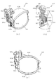
次いで、図5から図13を参照して、動作ユニット300について説明する。まず、図5から図7を参照して、背面ケース310への各ユニット400〜800の収容構造について説明する。
Next, the
図5は、動作ユニット300の正面斜視図であり、図6及び図7は、分解した動作ユニット300を正面視した動作ユニット300の分解正面斜視図である。なお、図7では、
第2スライド動作ユニット800が背面ケース310に装着された状態が図示される。
5 is a front perspective view of the
A state in which the second
図5から図7に示すように、動作ユニット300は、底壁部311と、その底壁部311の外縁から立設される外壁部312とから一面側(図6紙面手前側)が開放された箱状に形成される背面ケース310を備える。背面ケース310は、その底壁部311の中央に矩形状の開口311aが開口形成されることで、正面視矩形の枠状に形成される。開口311aは、第3図柄表示装置81(図2参照)の外形に対応した(即ち、第3図柄表示装置81を配設可能な)大きさに形成される。
As shown in FIGS. 5 to 7, the
動作ユニット300は、背面ケース310の内部空間に、揺動動作ユニット400、第1スライド動作ユニット500、箱形ユニット600、装飾役物ユニット700及び第2スライド動作ユニット800がそれぞれ収容され、これを1ユニットとして構成される。
In the
具体的には、第2スライド動作ユニット800は、背面ケース310の外壁部312の内側面が形成する形状よりも若干小さな外形で形成され、外壁部312の内側面に当接しながら、外壁部312に囲われる態様で底壁部311に配設される(図7参照)。第2スライド動作ユニット800は、組立状態(図5参照)において、正面視で背面ケース310の開口311aと一致する位置に矩形状の開口が形成される。
Specifically, the second
この図7に示す状態に対し、揺動動作ユニット400、第1スライド動作ユニット500、箱形ユニット600及び装飾役物ユニット700は、第2スライド動作ユニット800の正面側に、それぞれ重ね合わされた積層状態で配設され、背面ケース310に収容される(図5参照)。
In the state shown in FIG. 7, the
このように、本実施形態では、所定の動作ユニット(例えば、第2スライド動作ユニット800)に対し、他の動作ユニット(例えば、第1スライド動作ユニット500)が正面側に重ね合わされた積層状態で配設されるので、正面視において、所定の動作ユニットを、他の動作ユニットによって遮蔽することができる。 Thus, in the present embodiment, in a stacked state in which another operation unit (for example, the first slide operation unit 500) is superimposed on the front side with respect to a predetermined operation unit (for example, the second slide operation unit 800). Since it is disposed, the predetermined operation unit can be shielded by another operation unit in the front view.
言い換えれば、遊技盤13(図2参照)が光透過性材料から形成され、その遊技盤13の背面側に配設される動作ユニットを遊技者が視認可能とされる場合に、所定の動作ユニットの必要な部分のみを遊技者に視認させ、他の部分を他の動作ユニットにより遊技者から遮蔽することができる。これにより、他の動作ユニットによって遮蔽される所定の演出部材については、その全体が遊技者から視認されることを前提として設計する必要がないので、その設計の自由度の向上を図ることができる。
In other words, when the game board 13 (see FIG. 2) is formed of a light-transmitting material and the player can visually recognize the operation unit disposed on the back side of the
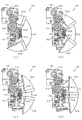
次いで、図8から図10を参照して、起立役物400、第1スライド動作ユニット500、および第2スライド動作ユニット800の動作態様の概略について説明する。なお、図8から図10の説明においては、図5から図7を適宜参照する。
Next, with reference to FIGS. 8 to 10, an outline of operation modes of the standing
図8から図10は、動作ユニット300の正面図である。なお、図8では揺動動作ユニット400の起立役物410及びアーム部材420が張出位置に配置された状態が、図9では第1スライド動作ユニット500の傾倒役物510が張出位置に配置された状態が、図10では第2スライド動作ユニット800の各スライド役物810,820,830,840が張出位置に配置された状態が、それぞれ図示される。
8 to 10 are front views of the
図8に示すように、揺動動作ユニット400は、基端側が揺動可能に軸支されるアーム部材420と、そのアーム部材420の基端側の反対側である揺動端側に揺動可能に軸支される起立役物410とを備えると共に、これらのアーム部材420及び起立役物410を、図5に示す退避位置(原点位置)と図8に示す張出位置との間で動作させる。図5に示す退避位置(原点位置)では、起立役物410、及びアーム部材420は、背面ケース310の開口311aの下方に退避され、遊技者から視認不能とされる(図2参照)。一方、図8に示す張出位置では、アーム部材420が持ち上げられ、起立部材410が背面ケース310の開口311aの中央(即ち、第3図柄表示装置81の正面、図2参照)に配置される。
As shown in FIG. 8, the
図9に示すように、第1スライド動作ユニット500は、斜め下方にスライド移動される傾倒役物510と、回動軸520aを回転軸として時計回り、及び反時計回りに回動可能な回動役物520とを備えている。傾倒役物510は、図5に示す退避位置(原点位置)と図9に示す張出位置との間で動作する。図5に示す退避位置(原点位置)では、傾倒役物510は、背面ケース310の開口311aの右方に退避される(図2参照)。一方、図9に示す張出位置では、傾倒役物510が背面ケース310の開口311aの中央(即ち、第3図柄表示装置81の正面、図2参照)に配置される。
As shown in FIG. 9, the first
図10に示すように、第2スライド動作ユニット800は、スライド移動可能に形成される各スライド役物810,820,830,840を備えると共に、それらの各スライド役物810,820,830,840を、図5に示す退避位置(原点位置)と、図10に示す張出位置との間で動作させる。図5に示す退避位置(原点位置)において、右側スライド役物810、および左側スライド役物820が、背面ケース310の開口311aの左右外方に退避されると共に、上側スライド役物830、および下側スライド役物840が、背面ケース310の開口311aの上下外方に退避され、遊技者から視認不能とされる(図2参照)。一方、図10に示す張出位置では、各スライド役物810,820,830,840が背面ケース310の開口311aの中央(即ち、第3図柄表示装置81の正面、図2参照)に配置される。
As shown in FIG. 10, the second
また、右側スライド役物810と、左側スライド役物820とは、同一平面上を動作するように構成されている。図10に示した通り、右側スライド役物810の張出位置は、左側スライド役物820の張出位置よりも右側であり、右側スライド役物810と左側スライド役物820とが互いに干渉し合う(接触する)ことはない。同様に上側スライド役物830と、下側スライド役物840とも同一平面上を動作するように構成されている。図10に示した通り、上側スライド役物830の張出位置は、下側スライド役物840の張出位置よりも上側であり、上側スライド役物830と下側スライド役物840とが互いに干渉し合う(接触する)ことはない。
Further, the
更に、右側スライド役物810と、左側スライド役物820とが動作する平面は、上側スライド役物830と、下側スライド役物840とが動作する平面よりも遊技盤13に対して手前側である(図10参照)。よって、右側スライド役物810、または左側スライド役物820によって上側スライド役物830、または下側スライド役物840の動作が妨げられることはない。また、逆に、上側スライド役物830、または下側スライド役物840によって右側スライド役物810、または左側スライド役物820の動作が妨げられることもない。従って、各スライド役物810,820,830,840の動作の自由度を高めることができるので、動作ユニット300の演出効果を高めることができる。
Further, the plane on which the
なお、第2スライド動作ユニット800は、各スライド役物810,820,830,840が張り出した状態において、正面視で「ハート」の形状を視認可能に形成される。
The second
次に、図11〜図13を参照して、動作ユニット300を構成する複数のユニットが複合的に動作した場合について説明する。まず、図11は、第1スライド動作ユニット500の傾倒部材510と、第2スライド動作ユニット800の各スライド役物810,820,830,840とが張出位置に配置された場合における動作ユニット300の正面図である。
Next, a case where a plurality of units constituting the
図11に示した通り、傾倒部材510は遊技盤13に対して第2スライド動作ユニット800よりも手前側を動作する。即ち、第2スライド動作ユニット800の各スライド役物810,820,830,840がどのような配置であっても、傾倒部材510の動作が妨げられる(干渉される)ことはない。また、傾倒部材510がどのような配置であっても、各スライド役物810,820,830,840の動作が妨げられる(干渉される)ことはない。よって、傾倒部材510と、各スライド役物810,820,830,840との動作の自由度を高めることができるので、動作ユニット300の演出効果を高めることができる。
As shown in FIG. 11, the tilting
ここで、第1スライド動作ユニット500と第3図柄表示装置81(図2参照)との間には第2スライド動作ユニット800が配設されるため、第1スライド動作ユニット500と第3図柄表示装置81との間には第2スライド動作ユニット800分の隙間が生じる。そのため、第1スライド動作ユニット500の傾倒部材510のみが張出位置に配置される場合、正面視で第3図柄表示装置81の表示領域P(図2参照)の一部を視認できないように遮蔽することはできるが、遊技者が斜め方向(例えば正面視から左右方向に傾いた方向)から隙間を覗いて第3図柄表示装置81の表示領域Pを視認することを防止することは難しい。
Here, since the second
これに対し、図11に示すように、第1スライド動作ユニット500の傾倒部材510と第2スライド動作ユニット800の各スライド役物810,820,830,840とが共に張出位置に配置されることで、遊技者が斜め方向から覗く隙間を各スライド役物810,820,830,840で埋めることができる。これにより、第3図柄表示装置81の表示領域Pの一部を視認できないように確実に遮蔽することができ、動作ユニット300の演出効果を向上させることができる。
On the other hand, as shown in FIG. 11, the tilting
図12は、揺動動作ユニット400の起立役物410、およびアーム部材420と、第2スライド動作ユニット800の各スライド役物810,820,830,840とが張出位置に配置された場合における動作ユニット300の正面図である。
FIG. 12 shows a case where the standing
図12に示した通り、起立役物410、およびアーム部材420は、遊技盤13に対して第2スライド動作ユニット800よりも手前側を動作する。即ち、第2スライド動作ユニット800の各スライド役物810,820,830,840がどのような配置であっても、起立役物410、およびアーム部材420の動作が妨げられる(干渉される)ことはない。また、起立役物410、およびアーム部材420がどのような配置であっても、各スライド役物810,820,830,840の動作が妨げられる(干渉される)ことはない。よって、起立役物410、アーム部材420、および各スライド役物810,820,830,840との動作の自由度を高めることができるので、動作ユニット300の演出効果を高めることができる。
As shown in FIG. 12, the standing
ここで、揺動動作ユニット400と第3図柄表示装置81(図2参照)との間には第2スライド動作ユニット800が配設されるため、揺動動作ユニット400と第3図柄表示装置81との間には第2スライド動作ユニット800分の隙間が生じる。そのため、揺動動作ユニット400の起立役物410のみが張出位置に配置される場合、正面視で第3図柄表示装置81の表示領域P(図2参照)の一部を視認できないように遮蔽することはできるが、遊技者が斜め方向(例えば正面視から左右方向に傾いた方向)から隙間を覗いて第3図柄表示装置81の表示領域Pを視認することを防止することは難しい。
Here, since the second
これに対し、図12に示すように、揺動動作ユニット400の起立役物410と第2スライド動作ユニット800の各スライド役物810,820,830,840とが共に張出位置に配置されることで、遊技者が斜め方向から覗く隙間を各スライド役物810,820,830,840で埋めることができる。これにより、第3図柄表示装置81の表示領域P(図2参照)の一部を視認できないように確実に遮蔽することができ、動作ユニット300の演出効果を向上させることができる。
On the other hand, as shown in FIG. 12, the standing
図13は、装飾役物ユニット700の中央揺動役物720と、第2スライド動作ユニット800の各スライド役物810,820,830,840とが張出位置に配置された場合における動作ユニット300の正面図である。ここで、図13に示すように、装飾役物ユニット700は、左側揺動役物710、中央揺動役物720、右側揺動役物730を有して構成され、中央揺動役物720を、図5に示す退避位置(原点位置)と図13に示す張出位置との間で動作させる。また、装飾ユニット700は、各揺動役物710,720,730を退避位置(原点位置)(図5参照)において揺動動作させる。
FIG. 13 shows the
なお、中央揺動役物720は、遊技盤13に対して左側揺動役物710、および右側揺動役物730よりも手前側に配設されている(即ち、中央揺動役物720は、左側揺動役物710、および右側揺動役物730と同一平面上にない)ので、左側揺動役物710や、右側揺動役物730を揺動させたとしても、中央揺動役物720に干渉(接触)することはない。また、中央揺動役物720に対して揺動動作や張り出し動作をさせたとしても、左側揺動役物710や、右側揺動役物730に干渉(接触)することはない。よって、各揺動役物710,720,730が、互いに他の揺動役物の動作を妨げあうことを抑制し、動作の自由度を高めることができる。従って、動作ユニット300の演出効果を高めることができる。
The central swinging
また、中央揺動役物720は、遊技盤13に対して、各スライド役物810,820,830,840よりも手前側に配設されている。よって、中央揺動役物720と、各スライド役物810,820,830,840とを互いに干渉させることなく動作させることができる。従って、動作の自由度を高めることができるので、動作ユニット300の演出効果を高めることができる。
Further, the
箱形ユニット600は、他の動作ユニット400,500,700,800に備えられるような、背面ケース310の開口311aの中央(即ち、第3図柄表示装置81の正面)に張り出す部材を持たない。そのため、箱形ユニット600は、常に背面ケース310の開口311aの左方(図5参照)に配置された状態に保たれる。
The box-shaped
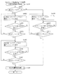
このように、各ユニット400〜800は、それぞれ独立して動作可能に形成されると共に、上述したように、重ね合わされた(積層された)状態で配設されるので、各ユニット400〜800のうちの層を違えて配設されるものについては、例え動作部材が背面ケース310の開口311aの内方に張り出す態様のものであっても同時に動作させることができる。即ち、図8から図13で例示したように、各ユニット400〜800をそれぞれ単体で動作させるだけでなく、これらの動作を組み合わせることができるので、その演出効果を高めることができる。なお、各ユニット400〜700が同じ層に配設され、それらの各ユニット400〜700と、第2スライド動作ユニット700とは層を違えて配設される(図7参照)。換言すると、揺動動作ユニット400、第1スライド動作ユニット500、装飾役物ユニット700のうち、いずれかのユニットに含まれる役物が張出位置にある場合に、他のユニットに含まれる役物を張出位置まで動作させてしまうと、互いに干渉し合ってしまう(接触してしまう)。詳細については後述するが、本パチンコ機10では、同じ層に配設されたユニットを構成する役物同士が干渉し合うことを抑制するために、ユニット単位で動作条件を規定している。そして、各ユニット400〜700のうちいずれかのユニットを構成する役物を動作させる場合は、他のユニットと干渉しないと判別される場合にのみ役物の動作を許可するように構成している。これにより、役物同士が衝突し、その衝突の衝撃で役物が破損してしまうことを抑制することができる。また、役物の動作が他の役物により妨げられることにより、役物の動作と第3図柄表示装置81に表示される表示演出の内容とがずれてしまい、遊技者に対して違和感を与えてしまうことを抑制することができる。
Thus, each
また、上述した通り、本実施形態のパチンコ機10では、多様な動作演出を実行するために複数の役物が設けられている。これらの役物は、それぞれ対応する役物用モータ229(図14参照)によって駆動される。ここで、各役物用モータ229を無制限に駆動させてしまうと、役物用モータ229によって使用可能な電流容量(定格電力)を上回る電流(電力)が消費されてしまい、正常な動作ができなくなってしまう虞がある。そこで、本実施形態のパチンコ機10では、各役物が駆動することにより消費される負荷電流値(消費電力)の合計値を算出し、その負荷電流値(消費電力)の合計値が、上述した電流容量(定格電力以下)を超えると判別した場合に、一部または全部の役物用モータ229の駆動を停止するように構成している。これにより、役物用モータ229に対して使用可能な電流容量(定格電力)を上回る負荷電流(電力)が消費されてしまうことを抑制することができる。よって、パチンコ機10が異常動作してしまったり、故障してしまったりすることを抑制することができる。なお、役物を停止するか否かの判別にあたっては、負荷電流の合計が電流容量を超えるか否かで行ってもよいし、消費電力の合計が定格電力を超えるか否かで行ってもよい。パチンコ機10に採用する電源装置15のスペックに基づき、条件のより厳しい方を判別対称として選択すればよい。
Further, as described above, in the
<第1実施形態における電気的構成について>
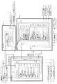
次に、図14を参照して、本パチンコ機10の電気的構成について説明する。図14は、パチンコ機10の電気的構成を示すブロック図である。
<Electrical Configuration in First Embodiment>
Next, the electrical configuration of the
主制御装置110には、演算装置である1チップマイコンとしてのMPU201が搭載されている。MPU201には、該MPU201により実行される各種の制御プログラムや固定値データを記憶したROM202と、そのROM202内に記憶される制御プログラムの実行に際して各種のデータ等を一時的に記憶するためのメモリであるRAM203と、そのほか、割込回路やタイマ回路、データ送受信回路などの各種回路が内蔵されている。なお、払出制御装置111や音声ランプ制御装置113などのサブ制御装置に対して動作を指示するために、主制御装置110から該サブ制御装置へ各種のコマンドがデータ送受信回路によって送信されるが、かかるコマンドは、主制御装置110からサブ制御装置へ一方向にのみ送信される。
The
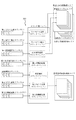
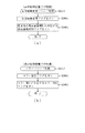
まず、ROM202の内容について、図15を参照して説明する。図15(a)に示すように、主制御装置110のROM202には、上記した固定値データの一部として、第1当たり乱数テーブル202a、第1当たり種別選択テーブル202b、第2当たり乱数テーブル202c、変動パターン選択テーブル202dが少なくとも記憶されている。
First, the contents of the
第1当たり乱数テーブル202a(図示せず)は、後述する第1当たり乱数カウンタC1の大当たり判定値が記憶されているデータテーブルである。詳細については、第1当たり乱数カウンタC1の説明と共に後述するが、始動入賞に基づいて取得した第1当たり乱数カウンタC1の値が、第1当たり乱数テーブル202aに規定されているいずれかの判定値と一致した場合に、特別図柄の大当たりであると判別される。 The first hit random number table 202a (not shown) is a data table in which a jackpot determination value of a first hit random number counter C1 described later is stored. The details will be described later together with the description of the first per-random number counter C1, but the value of the first per-random number counter C1 acquired based on the start winning is one of the determination values defined in the first per-random number table 202a. Is determined to be a special symbol jackpot.
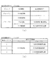
第1当たり種別選択テーブル202b(図15(b))は、大当たり種別を決定するための判定値が記憶されているデータテーブルであり、第1当たり種別カウンタC2の判定値が、各大当たり種別に対応付けて規定されている。具体的には、第1当たり種別カウンタC2の値が「0〜49」の範囲には、大当たりAが対応付けられて規定されている。また、第1当たり種別カウンタC2の値が「50〜99」の範囲には、大当たりBが対応付けられて規定されている。本実施形態のパチンコ機10では特別図柄の大当たりと判定された場合に、始動入賞に基づいて取得した第1当たり種別カウンタC2の値と、第1当たり種別選択テーブル202bとが比較され、第1当たり種別カウンタC2の値に対応する大当たり種別が選択される。
The first hit type selection table 202b (FIG. 15B) is a data table in which determination values for determining the big hit type are stored, and the determination value of the first hit type counter C2 is assigned to each big hit type. It is defined in association. Specifically, the jackpot A is defined in association with the range in which the value of the first hit type counter C2 is “0 to 49”. Further, in the range where the value of the first hit type counter C2 is “50 to 99”, the big hit B is associated and defined. In the
第2当たり乱数テーブル202c(図15(c))は、普通図柄の当たり判定値が記憶されているデータテーブルである。具体的には、普通図柄の通常状態において、普通図柄の当たりとなる判定値として、「5〜28」が規定されている(図15(c)参照)。また、普通図柄の高確率状態において、普通図柄の当たりとなる判定値として、「5〜204」が規定されている(図15(c)参照)。本実施形態のパチンコ機10では、普通入球口67を球が通過することに基づいて取得される第2当たり乱数カウンタC4の値と、第2当たり乱数テーブル202cとを参照し、普通図柄の当たりであるか否かを判定している。
The second hit random number table 202c (FIG. 15C) is a data table in which a hit determination value for a normal symbol is stored. Specifically, “5 to 28” is defined as a determination value that is a normal symbol hit in the normal state of the normal symbol (see FIG. 15C). Further, “5 to 204” is defined as a determination value that is a hit of the normal symbol in the high probability state of the normal symbol (see FIG. 15C). In the
変動パターン選択テーブル202d(図示なし)は、変動パターンの表示態様を決定するための変動種別カウンタCS1の判定値が表示態様毎にそれぞれ規定されているデータテーブルである。なお、変動パターン選択テーブル202dの詳細については、変動種別カウンタCS1の説明と共に後述する。 The variation pattern selection table 202d (not shown) is a data table in which the determination value of the variation type counter CS1 for determining the variation pattern display mode is defined for each display mode. The details of the variation pattern selection table 202d will be described later together with the description of the variation type counter CS1.
主制御装置110では、特別図柄の抽選、普通図柄の抽選、第1図柄表示装置37における表示の設定、第2図柄表示装置における表示の設定、および、第3図柄表示装置81における表示の設定といったパチンコ機10の主要な処理を実行する。そして、RAM203には、これらの処理を制御するための各種カウンタが設けられている。ここで、図16を参照して、主制御装置110のRAM203内に設けられるカウンタ等について説明する。これらのカウンタ等は、特別図柄の抽選、普通図柄の抽選、第1図柄表示装置37における表示の設定、第2図柄表示装置における表示の設定、および、第3図柄表示装置81における表示の設定などを行うために、主制御装置110のMPU201で使用される。
In
特別図柄の抽選や、第1図柄表示装置37および第3図柄表示装置81の表示の設定には、特別図柄の抽選に使用する第1当たり乱数カウンタC1と、特別図柄の大当たり種別を選択するために使用する第1当たり種別カウンタC2と、特別図柄における外れの停止種別を選択するために使用する停止種別選択カウンタC3と、第1当たり乱数カウンタC1の初期値設定に使用する第1初期値乱数カウンタCINI1と、変動パターン選択に使用する変動種別カウンタCS1とが用いられる。また、普通図柄の抽選には、第2当たり乱数カウンタC4が用いられ、第2当たり乱数カウンタC4の初期値設定には第2初期値乱数カウンタCINI2が用いられる。これら各カウンタは、更新の都度、前回値に1が加算され、最大値に達した後0に戻るループカウンタとなっている。
In order to select a special symbol lottery and the first symbol random number counter C1 used for the special symbol lottery and the special symbol lottery for setting the display of the first
各カウンタは、例えば、タイマ割込処理(図27参照)の実行間隔である2ミリ秒間隔で更新され、また、一部のカウンタは、メイン処理(図35参照)の中で不定期に更新されて、その更新値がRAM203の所定領域に設定されたカウンタ用バッファに適宜格納される。RAM203には、1つの実行エリアと第1入球口64に対応する4つの保留エリア(特図1保留第1〜第4エリア)と、第2入球口640に対応する4つの保留エリア(特図2保留第1〜第4エリア)からなる特別図柄保留球格納エリア203aが設けられており、これらの各エリアには、第1入球口64への入球タイミングに合わせて、第1当たり乱数カウンタC1、第1当たり種別カウンタC2及び停止種別選択カウンタC3の各値がそれぞれ格納される。また、RAM203には、1つの実行エリアと4つの保留エリア(保留第1〜第4エリア)とからなる普通図柄保留球格納エリア203bが設けられており、これらの各エリアには、球が左右何れかの第2入球口(スルーゲート)67を通過したタイミングに合わせて、第2当たり乱数カウンタC4の値が格納される。
Each counter is updated, for example, at an interval of 2 milliseconds, which is the execution interval of the timer interrupt process (see FIG. 27), and some counters are updated irregularly in the main process (see FIG. 35). Then, the updated value is appropriately stored in a counter buffer set in a predetermined area of the
各カウンタについて詳しく説明する。第1当たり乱数カウンタC1は、所定の範囲(例えば、0〜299)内で順に1ずつ加算され、最大値(例えば、0〜299の値を取り得るカウンタの場合は299)に達した後0に戻る構成となっている。第1当たり乱数カウンタC1が1周した場合、その時点の第1初期値乱数カウンタCINI1の値が当該第1当たり乱数カウンタC1の初期値として読み込まれる。 Each counter will be described in detail. The first per-random number counter C1 is incremented by 1 within a predetermined range (for example, 0 to 299) and reaches 0 after reaching the maximum value (for example, 299 for a counter that can take a value of 0 to 299). It is the composition which returns to. When the first per-random number counter C1 makes one round, the value of the first initial value random number counter CINI1 at that time is read as the initial value of the first per-random number counter C1.
また、第1初期値乱数カウンタCINI1は、第1当たり乱数カウンタC1と同一範囲で更新されるループカウンタとして構成される。即ち、例えば、第1当たり乱数カウンタC1が0〜299の値を取り得るループカウンタである場合には、第1初期値乱数カウンタCINI1もまた、0〜299の範囲のループカウンタである。この第1初期値乱数カウンタCINI1は、タイマ割込処理(図27参照)の実行毎に1回更新されると共に、メイン処理(図35参照)の残余時間内で繰り返し更新される。 The first initial value random number counter CINI1 is configured as a loop counter that is updated in the same range as the first random number counter C1. That is, for example, when the first random number counter C1 is a loop counter that can take a value of 0 to 299, the first initial value random number counter CINI1 is also a loop counter in the range of 0 to 299. The first initial value random number counter CINI1 is updated once every execution of the timer interrupt process (see FIG. 27), and is repeatedly updated within the remaining time of the main process (see FIG. 35).
第1当たり乱数カウンタC1の値は、例えば定期的に(本実施形態ではタイマ割込処理毎に1回)更新され、球が第1入球口64に入賞したタイミングでRAM203の特別図柄保留球格納エリア203aに格納される。そして、特別図柄の大当たりとなる乱数の値は、主制御装置110のROM202に格納される第1当たり乱数テーブル202aによって設定されており、第1当たり乱数カウンタC1の値が、第1当たり乱数テーブル202aによって設定された大当たりとなる乱数の値と一致する場合に、特別図柄の大当たりと判定する。また、この第1当たり乱数テーブル202aは、特別図柄の低確率時(特別図柄の低確率状態である期間)用と、その低確率時より特別図柄の大当たりとなる確率の高い高確率時(特別図柄の高確率状態である期間)用との2種類に分けられ、それぞれに含まれる大当たりとなる乱数の個数が異なって設定されている。このように、大当たりとなる乱数の個数を異ならせることにより、特別図柄の低確率時と特別図柄の高確率時とで、大当たりとなる確率が変更される。なお、特別図柄の高確率時用の第1当たり乱数テーブル202aと、特別図柄の低確率時用の第1当たり乱数テーブル202aとは、主制御装置110のROM202内に設けられている。
The value of the first random number counter C1 is updated, for example, periodically (in this embodiment, once for each timer interrupt process), and the special symbol holding ball in the
第1当たり種別カウンタC2は、特別図柄の大当たりとなった場合に、第1図柄表示装置37の表示態様を決定するものであり、所定の範囲(例えば、0〜99)内で順に1ずつ加算され、最大値(例えば、0〜99の値を取り得るカウンタの場合は99)に達した後0に戻る構成となっている。第1当たり種別カウンタC2の値は、例えば、定期的に(本実施形態ではタイマ割込処理毎に1回)更新され、球が第1入球口64に入賞したタイミングでRAM203の特別図柄保留球格納エリア203aに格納される。
The first hit type counter C2 determines the display mode of the first
ここで、特別図柄保留球格納エリア203aに格納された第1当たり乱数カウンタC1の値が、特別図柄の大当たりとなる乱数でなければ、即ち、特別図柄の外れとなる乱数であれば、第1図柄表示装置37に表示される停止図柄に対応した表示態様は、特別図柄の外れ時のものとなる。
Here, if the value of the first per-random number counter C1 stored in the special symbol reserved
一方で、特別図柄保留球格納エリア203aに格納された第1当たり乱数カウンタC1の値が、特別図柄の大当たりとなる乱数であれば、第1図柄表示装置37に表示される停止図柄に対応した表示態様は、特別図柄の大当たり時のものとなる。この場合、その大当たり時の具体的な表示態様は、同じ特別図柄保留球格納エリア203aに格納されている第1当たり種別カウンタC2の値が示す表示態様となる。
On the other hand, if the value of the first per-random number counter C1 stored in the special symbol holding
本実施形態のパチンコ機10における第1当たり乱数カウンタC1は、0〜299の範囲の2バイトのループカウンタとして構成されている。この第1当たり乱数カウンタC1において、特別図柄の低確率時に、特別図柄の大当たりとなる乱数値は1個あり、その乱数値である「7」は、低確率時用の第1当たり乱数テーブル202aに格納されている。このように特別図柄の低確率時には、乱数値の総数が300ある中で、大当たりとなる乱数値の総数が1なので、特別図柄の大当たりとなる確率は、「1/300」となる。
The first random number counter C1 in the
一方で、特別図柄の高確率時に、特別図柄の大当たりとなる乱数値は10個あり、その値である「4,38,64,99,122,151,183,218,249,270」は、高確率時用の第1当たり乱数テーブル202aに格納されている。このように特別図柄の高確率時には、乱数値の総数が300ある中で、大当たりとなる乱数値の総数が10なので、特別図柄の大当たりとなる確率は、「1/30」となる。 On the other hand, when the special symbol has a high probability, there are 10 random numbers that are jackpots of the special symbol, and the values “4, 38, 64, 99, 122, 151, 183, 218, 249, 270” are It is stored in the first per random number table 202a for high probability. Thus, when the special symbol has a high probability, the total number of random numbers that are jackpots is 10 among the total number of random number values, so the probability that the special symbol is jackpot is “1/30”.
なお、本実施形態では、低確率時用の第1当たり乱数テーブル202aに格納されている大当たりとなる乱数値と、高確率時用の第1当たり乱数テーブル202aに格納されている大当たりとなる乱数値とで、重複した値とならないように、それぞれの大当たりとなる乱数値を設定している。ここで、大当たりとなる乱数値としてパチンコ機10の状況にかかわらず常に用いられる値が存在すれば、その乱数値が出現するタイミングを解析される虞がある。即ち、解析されたタイミングに基づいて不正に大当たりを引き当てられやすくなるおそれがある。これに対して、本実施形態のように、状況に応じて(即ち、パチンコ機10が特別図柄の高確率状態か、特別図柄の低確率状態かに応じて)、大当たりとなる乱数値を変えることで、特別図柄の大当たりとなる乱数値を解析され難くすることができるので、不正に対する抑制を図ることができる。
In the present embodiment, the random number that is a big hit stored in the first per-random number table 202a for low probability and the random hit that is stored in the first per-random number table 202a for high probability. Random numbers that are big hits are set so that they do not overlap with numerical values. Here, if there is a value that is always used as a jackpot random value regardless of the situation of the
また、本実施形態のパチンコ機10における第1当たり種別カウンタC2の値は、0〜99の範囲のループカウンタとして構成されている。そして、図15(b)に示すように、この第1当たり種別カウンタC2において、乱数値が「0〜49」であった場合の大当たり種別は、「大当たりA」となる。また、値が「50〜99」であった場合の大当たり種別は、「大当たりB」となる。
Further, the value of the first hit type counter C2 in the
このように、本実施形態のパチンコ機10は、第1当たり種別カウンタC2が示す乱数の値によって、2種類の当たり種別(大当たりA、大当たりB)のどちらかが決定されるように構成されている。なお、第1当たり種別カウンタC2の値(乱数値)から、特別図柄の大当たり種別を決定するための乱数値は、第1当たり種別選択テーブル202b(図15(b)参照)により設定されており、このテーブルは、主制御装置110のROM202内に設けられている。
As described above, the
停止種別選択カウンタC3は、例えば0〜99の範囲内で順に1ずつ加算され、最大値(つまり99)に達した後0に戻る構成となっている。本実施形態では、停止種別選択カウンタC3によって、第3図柄表示装置81で表示される外れ時の停止種別が選択され、リーチが発生した後、最終停止図柄がリーチ図柄の前後に1つだけずれて停止する「前後外れリーチ」(例えば98,99)と、同じくリーチ発生した後、最終停止図柄がリーチ図柄の前後以外で停止する「前後外れ以外リーチ」(例えば90〜97の範囲)と、リーチ発生しない「完全外れ」(例えば0〜89の範囲)との3つの停止(演出)パターンが選択される。停止種別選択カウンタC3の値は、例えば定期的に(本実施形態ではタイマ割込処理毎に1回)更新され、球が第1入球口64に入賞したタイミングでRAM203の特別図柄保留球格納エリア203aに格納される。
For example, the stop type selection counter C3 is incremented by 1 within a range of 0 to 99, for example, and reaches a maximum value (that is, 99) and then returns to 0. In the present embodiment, the stop type at the time of release displayed on the third
なお、停止種別選択カウンタC3の値(乱数値)から、特別図柄の停止種別を決定するための乱数値は、停止種別選択テーブル(図示せず)により設定されており、このテーブルは、主制御装置110のROM202内に設けられている。また、本実施形態ではこのテーブルを、特別図柄の高確率時用と、特別図柄の低確率時用とに分けており、テーブルに応じて、外れの停止種別ごとに設定される乱数値の範囲を変えている。これは、パチンコ機10が特別図柄の高確率状態であるか、特別図柄の低確率状態であるか等に応じて、停止種別の選択比率を変更するためである。
The random value for determining the stop type of the special symbol from the value (random number value) of the stop type selection counter C3 is set by a stop type selection table (not shown). It is provided in the
例えば、高確率状態では、大当たりが発生し易いため必要以上にリーチ演出が選択されないように、「完全外れ」の停止種別に対応した乱数値の範囲が0〜89と広い高確率時用のテーブルが選択され、「完全外れ」が選択され易くなる。このテーブルは、「前後外れリーチ」が98,99と狭くなると共に「前後外れ以外リーチ」も90〜97と狭くなり、「前後外れリーチ」や「前後外れ以外リーチ」が選択され難くなる。また、低確率状態であれば、第1入球口64への球の入球時間を確保するために「完全外れ」の停止種別に対応した乱数値の範囲が0〜79と狭い低確率時用のテーブルが選択され、「完全外れ」が選択され難くなる。
For example, in a high-probability state, a table for a high-probability time with a wide range of random values from 0 to 89 corresponding to the stop type “completely out” is selected so that a reach effect is not selected more than necessary because a big hit is likely to occur. Is selected, and “completely off” is easily selected. In this table, the “front / rear detachment reach” is narrowed to 98,99, and the “reach other than front / rear detachment” is also narrowed to 90 to 97, making it difficult to select “rearward / rearward detachment reach” or “reach other than front / rear detachment”. In the low probability state, the random value range corresponding to the stop type “completely off” is 0 to 79 and the probability is low so as to secure the time for entering the ball into the
この停止種別選択テーブルは、「前後外れ以外リーチ」の停止種別に対応した乱数値の範囲が80〜97と広くなり、「前後外れ以外リーチ」が選択され易くなっている。よって、低確率状態では、演出時間の長いリーチ表示を多く行うことできるので、第1入球口64への球の入球時間を確保でき、第3図柄表示装置81による変動表示が継続して行われ易くなる。なお、後者のテーブルにおいても、「前後外れリーチ」の停止種別に対応した乱数値の範囲は98,99に設定される。
In this stop type selection table, the range of random values corresponding to the stop type of “reach other than front / rear out” is widened to 80 to 97, and “reach other than front / rear out” is easily selected. Therefore, in the low probability state, it is possible to perform a lot of reach display with a long production time, so it is possible to secure the time for entering the ball into the
変動種別カウンタCS1は、例えば0〜198の範囲内で順に1ずつ加算され、最大値(つまり198)に達した後0に戻る構成となっている。変動種別カウンタCS1によって、いわゆるノーマルリーチ、スーパーリーチ等の大まかな表示態様が決定される。表示態様の決定は、具体的には、図柄変動の変動時間の決定である。変動種別カウンタCS1により決定された変動時間に基づいて、音声ランプ制御装置113や表示制御装置114により第3図柄表示装置81で表示される第3図柄のリーチ種別や細かな図柄変動態様が決定される。変動種別カウンタCS1の値は、後述するメイン処理(図35参照)が1回実行される毎に1回更新され、当該メイン処理内の残余時間内でも繰り返し更新される。なお、変動種別カウンタCS1の値(乱数値)から、図柄変動の変動時間を一つ決定する乱数値を格納した変動パターン選択テーブル202d(図示せず)は、主制御装置110のROM202内に設けられている。
The variation type counter CS1 is, for example, incremented by 1 within a range of 0 to 198, and returns to 0 after reaching the maximum value (that is, 198). Rough display modes such as so-called normal reach and super reach are determined by the variation type counter CS1. Specifically, the display mode is determined by determining the variation time of the symbol variation. Based on the fluctuation time determined by the fluctuation type counter CS1, the voice
変動パターン選択テーブル202dには、例えば、外れ用の変動パターンとして、「外れ(長時間用)」、「外れ(短時間用)」、「外れノーマルリーチ」各種、「外れスーパーリーチ」各種、「外れスペシャルリーチ」各種が規定され、大当たりA・大当たりB共用の変動パターンとして、「共用ノーマルリーチ」各種、「共用スーパーリーチ」各種、「共用スペシャルリーチ」各種が規定され、大当たりA用の変動パターンとして、「スペシャルリーチ」各種が規定され、当たり・外れ共用の変動パターンとして、「共用ノーマルリーチ」各種、「共用スーパーリーチ」各種、「共用スペシャルリーチ」各種が規定されている。そして、変動パターン選択テーブル202dに規定された各種変動パターンから、予測された抽選結果や、予測された停止種別(大当たりの場合には大当たり種別)に応じて変動パターンが選定される。 The variation pattern selection table 202d includes, for example, “displacement (for a long time)”, “disconnection (for a short time)”, “disconnection normal reach”, “discovery super reach”, "Special reach" is defined, variation patterns of jackpot A and jackpot B shared, "common normal reach", "shared super reach", "shared special reach" is defined, variation pattern for jackpot A, Various types of “special reach” are defined, and “various common reach”, “common super reach”, and “common special reach” are defined as fluctuation patterns of common hit / miss. Then, a variation pattern is selected from the various variation patterns defined in the variation pattern selection table 202d according to the predicted lottery result or the predicted stop type (a jackpot type in the case of a jackpot).
第2当たり乱数カウンタC4は、例えば0〜239の範囲内で順に1ずつ加算され、最大値(つまり239)に達した後0に戻るループカウンタとして構成されている。また、第2当たり乱数カウンタC4が1周した場合、その時点の第2初期値乱数カウンタCINI2の値が当該第2当たり乱数カウンタC4の初期値として読み込まれる。第2当たり乱数カウンタC4の値は、本実施形態ではタイマ割込処理毎に、例えば定期的に更新され、球が左右何れかの第2入球口(スルーゲート)67を通過したことが検知された時に取得され、RAM203の普通図柄保留球格納エリア203bに格納される。
The second random number counter C4 is configured as a loop counter that is incremented one by one within a range of, for example, 0 to 239 and returns to 0 after reaching the maximum value (that is, 239). When the second random number counter C4 makes one round, the value of the second initial value random number counter CINI2 at that time is read as the initial value of the second random number counter C4. In this embodiment, the value of the second per-random number counter C4 is periodically updated, for example, every timer interrupt process, and it is detected that the ball has passed through either the left or right second entrance (through gate) 67. And is stored in the normal symbol holding
そして、第2図柄(普通図柄)の当たりとなる乱数の値は、主制御装置のROM202に格納される第2当たり乱数テーブル202c(図15(c)参照)によって設定されており、第2当たり乱数カウンタC4の値が、第2当たり乱数テーブルによって設定された当たりとなる乱数の値と一致する場合に、第2図柄(普通図柄)の当たりと判定する。また、この第2当たり乱数テーブルは、第2図柄(普通図柄)の低確率時(普通図柄の通常状態である期間)用と、その低確率時より普通図柄の当たりとなる確率の高い高確率時(普通図柄の時短状態である期間)用との2種類に分けられ、それぞれに含まれる大当たりとなる乱数の個数が異なって設定されている。このように、当たりとなる乱数の個数を異ならせることにより、普通図柄の低確率時と普通図柄の高確率時とで、当たりとなる確率が変更される。
The value of the random number that is the winning symbol of the second symbol (ordinary symbol) is set by the second random number table 202c (see FIG. 15C) stored in the
図15(c)に示すように、普通図柄の低確率時に、普通図柄の当たりとなる乱数値は24個あり、その範囲は「5〜28」となっている。これら乱数値は、低確率時用の第2当たり乱数テーブルに格納されている。このように普通図柄の低確率時には、乱数値の総数が240ある中で、当たりとなる乱数値の総数が24なので、普通図柄の当たりとなる確率は、「1/10」となる。
As shown in FIG. 15 (c), there are 24 random numbers that are hit by the normal symbol when the normal symbol has a low probability, and the range is “5-28”. These random number values are stored in the second random number table for low probability. As described above, when the normal symbol has a low probability, the total number of random numbers to be won is 24 among the total number of
パチンコ機10が普通図柄の低確率時である場合に、球が普通入球口67を通過すると、第2当たり乱数カウンタC4の値が取得されると共に、第2図柄表示装置において普通図柄の変動表示が30秒間実行される。そして、取得された第2当たり乱数カウンタC4の値が「5〜28」の範囲であれば当選と判定されて、第2図柄表示装置における変動表示が終了した後に、停止図柄(第2図柄)として「○」の図柄が点灯表示されると共に、第2入球口640に付随する電動役物が「0.2秒間×1回」だけ開放される。なお、本実施形態では、パチンコ機10が普通図柄の低確率時である場合に、普通図柄の当たりとなったら第2入球口640に付随する電動役物が「0.2秒間×1回」だけ開放されるが、開放時間や回数は任意に設定すれば良い。例えば、「0.5秒間×2回」開放しても良い。
When the
一方で、普通図柄の高確率時に、普通図柄の大当たりとなる乱数値は200個あり、その範囲は「5〜204」となっている。これらの乱数値は、高確率時用の第2当たり乱数テーブルに格納されている。このように普通図柄の低確率時には、乱数値の総数が240ある中で、大当たりとなる乱数値の総数が200なので、普通図柄の当たりとなる確率は、「1/1.2」となる。
On the other hand, when there is a high probability of a normal symbol, there are 200 random values that are jackpots of the normal symbol, and the range is “5-204”. These random number values are stored in the second random number table for high probability. In this way, when the normal symbol has a low probability, the total number of random numbers that are big hits is 200 among the total number of
パチンコ機10が普通図柄の高確率時である場合に、球が普通入球口67を通過すると、第2当たり乱数カウンタC4の値が取得されると共に、第2図柄表示装置において普通図柄の変動表示が3秒間実行される。そして、取得された第2当たり乱数カウンタC4の値が「5〜204」の範囲であれば当選と判定されて、第2図柄表示装置における変動表示が終了した後に、停止図柄(第2図柄)として「○」の図柄が点灯表示されると共に、第1入球口64が「1秒間×2回」開放される。このように、普通図柄の高確率時には、普通図柄の低確率時と比較して、変動表示の時間が「30秒→3秒」と非常に短くなり、更に、第2入球口640に付随する電動役物の開放期間が「0.2秒×1回→1秒間×2回」と非常に長くなるので、球が第2入球口640へと入球し易い状態となる。なお、第2当たり乱数カウンタC4の値(乱数値)から、普通図柄の当たりか否かを判定する乱数値を格納した第2当たり乱数テーブル202c(図15(c)参照)は、ROM202内に設けられている。なお、本実施形態では、パチンコ機10が普通図柄の高確率時である場合に、普通図柄の当たりとなったら第2入球口640に付随する電動役物が「1秒間×2回」だけ開放されるが、開放時間や回数は任意に設定すれば良い。例えば、「3秒間×3回」開放しても良い。
When the
第2初期値乱数カウンタCINI2は、第2当たり乱数カウンタC4と同一範囲で更新されるループカウンタとして構成され(値=0〜239)、タイマ割込処理(図27参照)毎に1回更新されると共に、メイン処理(図35参照)の残余時間内で繰り返し更新される。 The second initial value random number counter CINI2 is configured as a loop counter that is updated in the same range as the second random number counter C4 (value = 0 to 239), and is updated once every timer interrupt process (see FIG. 27). And repeatedly updated within the remaining time of the main process (see FIG. 35).
このように、RAM203には種々のカウンタ等が設けられており、主制御装置110では、このカウンタ等の値に応じて大当たり抽選や第1図柄表示装置37および第3図柄表示装置81における表示の設定、第2図柄表示装置における表示結果の抽選といったパチンコ機10の主要な処理を実行することができる。
As described above, the
図14に戻り、説明を続ける。RAM203は、図16に図示した各種カウンタのほか、MPU201の内部レジスタの内容やMPU201により実行される制御プログラムの戻り先番地などが記憶されるスタックエリアと、各種のフラグおよびカウンタ、I/O等の値が記憶される作業エリア(作業領域)とを有している。
Returning to FIG. 14, the description will be continued. In addition to the various counters shown in FIG. 16, the
なお、RAM203は、パチンコ機10の電源の遮断後においても電源装置115からバックアップ電圧が供給されてデータを保持(バックアップ)できる構成となっており、RAM203に記憶されるデータは、すべてバックアップされる。
Note that the
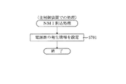
停電などの発生により電源が遮断されると、その電源遮断時(停電発生時を含む。以下同様)のスタックポインタや、各レジスタの値がRAM203に記憶される。一方、電源投入時(停電解消による電源投入を含む。以下同様)には、RAM203に記憶される情報に基づいて、パチンコ機10の状態が電源遮断前の状態に復帰される。RAM203への書き込みはメイン処理(図35参照)によって電源遮断時に実行され、RAM203に書き込まれた各値の復帰は電源投入時の立ち上げ処理(図34参照)において実行される。なお、MPU201のNMI端子(ノンマスカブル割込端子)には、停電等の発生による電源遮断時に、停電監視回路252からの停電信号SG1が入力されるように構成されており、その停電信号SG1がMPU201へ入力されると、停電時処理としてのNMI割込処理(図33参照)が即座に実行される。
When the power is shut down due to the occurrence of a power failure or the like, the stack pointer and the value of each register when the power is shut off (including when the power failure occurs, the same applies hereinafter) are stored in the
また、RAM203は、図14に示すように、特別図柄保留球格納エリア203aと、普通図柄保留球格納エリア203bと、特図1保留球数カウンタ203cと、特図2保留球数カウンタ203dと、普通図柄保留球数カウンタ203eと、確変フラグ203fと、時短中カウンタ203gとを有している。
Further, as shown in FIG. 14, the
特別図柄保留球格納エリア203aは、1つの実行エリアと、第1入球口64に対応する4つの保留エリア(特図1保留第1エリア〜特図1保留第4エリア)と、第2入球口640に対応する4つの保留エリア(特図2保留第1エリア〜特図2保留第4エリア)とを有している。これらの各エリアには、第1当たり乱数カウンタC1、第1当たり種別カウンタC2、及び停止種別選択カウンタC3の各値がそれぞれ格納される。
The special symbol reserved
より具体的には、球が第1入球口64へ入賞(始動入賞)したタイミングで、各カウンタC1〜C3の各値が取得され、その取得されたデータが、第1入球口64に対応する4つの保留エリア(特図1保留第1エリア〜特図1保留第4エリア)の空いているエリアの中で、エリア番号(第1〜第4)の小さいエリアから順番に記憶される。つまり、エリア番号の小さいエリアほど、時間的に古い入賞に対応するデータが記憶され、保留第1エリアには、時間的に最も古い入賞に対応するデータが記憶される。なお、4つの保留エリアの全てにデータが記憶されている場合には、新たに何も記憶されない。
More specifically, each value of each of the counters C1 to C3 is acquired at the timing when the ball wins the first entrance 64 (start winning), and the acquired data is stored in the
なお、第2入球口640へと球が入球した場合についても同様である。即ち、球が第2入球口640へと入賞(始動入賞)したタイミングで、各カウンタC1〜C3の各値が取得され、その取得されたデータが、第2入球口640に対応する4つの保留エリア(特図2保留第1エリア〜特図2保留第4エリア)の空いているエリアの中で、エリア番号(第1〜第4)の小さいエリアから順番に記憶される。また、第2入球口640に対応する4つの保留エリアのすべてにデータが記憶されている場合には、新たに何も記憶されない。
The same applies to the case where a ball enters the
主制御装置110において、特別図柄の抽選が行われる場合には、特別図柄保留球格納エリア203aの特図1保留第1エリア、または特図2保留第1エリアのどちらかに記憶されている各カウンタC1〜C3の各値が、実行エリアへシフトされ(移動させられ)、その実行エリアに記憶された各カウンタC1〜C3の各値に基づいて、特別図柄の抽選などの判定が行われる。なお、本実施形態のパチンコ機10では、第2入球口640へと球が入球したことに基づく特別図柄の抽選(特図2の抽選)を、第1入球口64へと球が入球したことに基づく特別図柄の抽選(特図1の抽選)よりも優先的に実行するように構成されている。即ち、特図2保留第1エリアにデータが記憶されている場合は、特図1保留第1エリアにデータが記憶されているか否かに関わらず、シフト処理において特図2保留第1エリアに記憶されているデータが実行エリアにシフトされる。
When a special symbol lottery is performed in the
特図1保留第1エリア、または特図2保留第1エリアのうち、いずれかの保留第1エリアから実行エリアへとデータをシフトすると、データシフトを行われた保留第1エリアが空き状態となる。そこで、他の保留エリア(保留第2エリア〜保留第4エリア)に記憶されている入賞のデータを、エリア番号の1小さい保留エリア(保留第1エリア〜保留第3エリア)に詰めるシフト処理が行われる。本実施形態では、特別図柄保留球格納エリア203aにおいて、入賞のデータが記憶されている保留エリア(保留第2エリア〜保留第4エリア)についてのみデータのシフトが行われる。
When data is shifted from either the reserved first area to the execution area of the special figure 1 reserved first area or the special figure 2 reserved first area, the reserved first area where the data shift has been performed is in an empty state. Become. Therefore, a shift process is performed in which winning data stored in other reserved areas (holding second area to holding fourth area) is packed into a holding area having a smaller area number (holding first area to holding third area). Done. In the present embodiment, in the special symbol reserved
本パチンコ機10では、球が第1入球口64、または第2入球口640へと入賞(始動入賞)し、その始動入賞に応じて各カウンタC1〜C3の各値が取得されると直ちに、本来の特別図柄の大当たり抽選とは別に、その取得された各カウンタC1〜C3の各値から、本来の抽選が行われた場合に得られる各種情報が予測(推定)される。このように、本来の特別図柄の抽選が行われる前に、始動入賞に対応するデータ(各カウンタC1〜C3の各値)に基づいて、本来の抽選が行われた場合に得られる各種情報を予測することを、以後、特別図柄の抽選結果を先読みすると記載する。なお、各種情報としては、当否、停止種別、変動パターンなどが該当する。
In the
そして、先読みが終了すると、先読みにより得られた各種情報(当否、停止種別、変動パターン)を含む入賞情報コマンドが音声ランプ制御装置113へ送信される(図30のS407,S414参照)。入賞情報コマンドが音声ランプ制御装置113によって受信されると、音声ランプ制御装置113は、入賞情報コマンドから、当否、停止種別、および変動パターンを抽出し、それらを入賞情報としてRAM233の入賞情報格納エリア223aに格納する。
When the prefetching is completed, a winning information command including various types of information (presence / absence, stop type, variation pattern) obtained by the prefetching is transmitted to the sound lamp control device 113 (see S407 and S414 in FIG. 30). When the winning information command is received by the sound
普通図柄保留球格納エリア203bは、特別図柄保留球格納エリア203aと同様に、1つの実行エリアと、4つの保留エリア(保留第1エリア〜保留第4エリア)とを有している。これらの各エリアには、第2当たり乱数カウンタC4が格納される。
Similarly to the special symbol reserved
より具体的には、球が普通入球口67を通過したタイミングで、カウンタC4の値が取得され、その取得されたデータが、4つの保留エリア(保留第1エリア〜保留第4エリア)の空いているエリアの中で、エリア番号(第1〜第4)の小さいエリアから順番に記憶される。つまり、特別図柄保留球格納エリア203aと同様に、入賞した順序が保持されつつ、入賞に対応するデータが格納される。なお、4つの保留エリアの全てにデータが記憶されている場合には、新たに何も記憶されない。
More specifically, the value of the counter C4 is acquired at the timing when the ball has passed through the
その後、主制御装置110において、普通図柄の当たりの抽選が行われる場合には、普通図柄保留球格納エリア203bの保留第1エリアに記憶されているカウンタC4の値が、実行エリアへシフトされ(移動させられ)、その実行エリアに記憶されたカウンタC4の値に基づいて、普通図柄の当たりの抽選などの判定が行われる。
Thereafter, when the
なお、保留第1エリアから実行エリアへデータをシフトすると、保留第1エリアが空き状態となるので、特別図柄保留球格納エリア203aの場合と同様に、他の保留エリアに記憶されている入賞のデータを、エリア番号の1小さい保留エリアに詰めるシフト処理が行われる。また、データのシフトも、入賞のデータが記憶されている保留エリアについてのみ行われる。
Note that when the data is shifted from the reserved first area to the execution area, the reserved first area becomes empty. Therefore, as in the case of the special symbol reserved
特図1保留球数カウンタ203cは、第1入球口64への入球(始動入賞)に基づいて第1図柄表示装置37で行われる特別図柄(第1図柄)の変動表示(第3図柄表示装置81で行われる変動表示)の保留球数(待機回数)を最大4回まで計数するカウンタである。この特図1保留球数カウンタ203cは、初期値がゼロに設定されており、第1入球口64へ球が入球して変動表示の保留球数が増加する毎に、第1入球口64に対応する保留球数が最大値4まで1加算される(図30のS404参照)。一方、特図1保留球数カウンタ203cは、新たに特別図柄の変動表示が実行される毎に、1減算される(図28のS206参照)。
The special figure 1 reserved
特図2保留球数カウンタ203dは、第2入球口640への入球(始動入賞)に基づいて第1図柄表示装置37で行われる特別図柄(第1図柄)の変動表示(第3図柄表示装置81で行われる変動表示)の保留球数(待機回数)を最大4回まで計数するカウンタである。この特図2保留球数カウンタ203dは、初期値がゼロに設定されており、第2入球口640へ球が入球して変動表示の保留球数が増加する毎に、第2入球口640に対応する保留球数が最大値4まで1加算される(図30のS411参照)。一方、特図2保留球数カウンタ203dは、新たに特別図柄の変動表示が実行される毎に、1減算される(図28のS209参照)。
The special figure 2 reserved
これらの特図1保留球数カウンタ203cの値(第1入球口64への入球に基づく変動表示の保留回数N1)、および特図2保留球数カウンタ203dの値(第2入球口640への入球に基づく変動表示の保留回数N2)は、保留球数コマンドによって音声ランプ制御装置113に通知される(図28のS207,S210、図30のS405,S412参照)。保留球数コマンドは、特図1保留球数カウンタ203c、および特図2保留球数カウンタ203dの値が変更される度に、主制御装置110から音声ランプ制御装置113に対して送信されるコマンドである。
The value of the special figure 1 reserved
音声ランプ制御装置113は、特図1保留球数カウンタ203c、および特図2保留球数カウンタ203dの値が変更される度に、主制御装置110より送信される保留球数コマンドによって、主制御装置110に保留された変動表示の保留球数そのものの値を取得することができる。これにより、音声ランプ制御装置113の特別図柄保留球数カウンタ223bによって管理される変動表示の保留球数が、ノイズ等の影響によって、主制御装置110に保留された実際の変動表示の保留球数からずれてしまった場合であっても、次に受信する保留球数コマンドによって、そのずれを修正することができる。
The voice
なお、音声ランプ制御装置113は、保留球数コマンドに基づいて保留球数を管理し、保留球数が変化する度に表示制御装置114に対して、保留球数を通知するための表示用保留球数コマンドを送信する。表示制御装置114は、この表示用保留球数コマンドによって通知された保留球数を基に、第3図柄表示装置81の小領域Ds1に保留球数図柄を表示する。
The voice
普通図柄保留球数カウンタ203eは、普通入球口67における球の通過に基づいて第2図柄表示装置で行われる普通図柄(第2図柄)の変動表示の保留球数(待機回数)を最大4回まで計数するカウンタである。この普通図柄保留球数カウンタ203eは、初期値がゼロに設定されており、球が普通入球口67を通過して変動表示の保留球数が増加する毎に、最大値4まで1加算される(図32のS604参照)。一方、普通図柄保留球数カウンタ203eは、新たに普通図柄(第2図柄)の変動表示が実行される毎に、1減算される(図31のS505参照)。
The normal symbol reserved
球が左右何れかの普通入球口67を通過した場合に、この普通図柄保留球数カウンタ203eの値(普通図柄における変動表示の保留回数M)が4未満であれば、第2当たり乱数カウンタC4の値が取得され、その取得されたデータが、普通図柄保留球格納エリア203bに記憶される(図32のS605)。一方、球が左右何れかの普通入球口67を通過した場合に、この普通図柄保留球数カウンタ203eの値が4であれば、普通図柄保留球格納エリア203bには新たに何も記憶されない(図32のS603:No)。
If the value of the normal symbol reserved
確変フラグ203fは、パチンコ機10が特別図柄の確変状態(特別図柄の高確率状態)であるか否かを示すフラグである。この確変フラグ203fは、オンであればパチンコ機10が特別図柄の確変状態であることを示し、オフであればパチンコ機10が特別図柄の通常状態(特別図柄の低確率状態)であることを示す。この確変フラグ203fは、初期値がオフに設定されており、大当たりA(確変大当たり)に当選すると、その大当たりAの終了を設定する際に確変フラグ203fがオンに設定される。
The
MPU201によって特別図柄変動開始処理(図29参照)が実行されると、特別図柄の抽選が行われる。特別図柄変動開始処理では、確変フラグ203fが参照され、オンであれば、高確率時用の第1当たり乱数テーブル202aに基づいて、特別図柄の抽選が行われる一方、確変フラグ203fがオフであれば、低確率時用の第1当たり乱数テーブル202aに基づいて、特別図柄の抽選が行われる(図29のS303,S304参照)。
When the special symbol variation start process (see FIG. 29) is executed by the
時短中カウンタ203gは、パチンコ機10が普通図柄の時短状態であるか否かを示すカウンタであり、時短中カウンタ203gの値が1以上であれば、パチンコ機10が普通図柄の時短状態であることを示し、時短中カウンタ203gの値が0であれば、パチンコ機10が普通図柄の通常状態であることを示す。この時短中カウンタ203gは、初期値がゼロに設定されており、大当たりB(時短大当たり)に当選すると、その大当たりBの終了を設定する際に値に100が設定される。即ち、大当たりBになった場合には、時短中カウンタ203gの値が幾つであるかに関わらず、新たに100が設定される。
The hour /
普通図柄の当たりの抽選が行われる場合には、時短中カウンタ203gの値が参照され、その値が1以上であれば、高確率時用の第2当たり乱数テーブルに基づいて、普通図柄の抽選が行われる一方、時短中カウンタ203gの値が0であれば、低確率時用の第2当たり乱数テーブルに基づいて、普通図柄の抽選が行われる(図31のS510,S511参照)。
When the normal symbol winning lottery is performed, the value of the hour /
主制御装置110のMPU201には、アドレスバス及びデータバスで構成されるバスライン204を介して入出力ポート205が接続されている。入出力ポート205には、払出制御装置111、音声ランプ制御装置113、第1図柄表示装置37、第2図柄表示装置、第2図柄保留ランプ84、特定入賞口65aの開閉板の下辺を軸として前方側に開閉駆動するための大開放口ソレノイドや電動役物を駆動するためのソレノイドなどからなるソレノイド209が接続され、MPU201は、入出力ポート205を介してこれらに対し各種コマンドや制御信号を送信する。
An input /
また、入出力ポート205には、図示しないスイッチ群やセンサ群などからなる各種スイッチ208や、電源装置115に設けられた後述のRAM消去スイッチ回路253が接続され、MPU201は各種スイッチ208から出力される信号や、RAM消去スイッチ回路253より出力されるRAM消去信号SG2に基づいて各種処理を実行する。
The input /
払出制御装置111は、払出モータ216を駆動させて賞球や貸出球の払出制御を行うものである。演算装置であるMPU211は、そのMPU211により実行される制御プログラムや固定値データ等を記憶したROM212と、ワークメモリ等として使用されるRAM213とを有している。
The
払出制御装置111のRAM213は、主制御装置110のRAM203と同様に、MPU211の内部レジスタの内容やMPU211により実行される制御プログラムの戻り先番地などが記憶されるスタックエリアと、各種のフラグおよびカウンタ、I/O等の値が記憶される作業エリア(作業領域)とを有している。RAM213は、パチンコ機10の電源の遮断後においても電源装置115からバックアップ電圧が供給されてデータを保持(バックアップ)できる構成となっており、RAM213に記憶されるデータは、すべてバックアップされる。なお、主制御装置110のMPU201と同様、MPU211のNMI端子にも、停電等の発生による電源遮断時に停電監視回路252から停電信号SG1が入力されるように構成されており、その停電信号SG1がMPU211へ入力されると、停電時処理としてのNMI割込処理(図33参照)が即座に実行される。
The
払出制御装置111のMPU211には、アドレスバス及びデータバスで構成されるバスライン214を介して入出力ポート215が接続されている。入出力ポート215には、主制御装置110や払出モータ216、発射制御装置112などがそれぞれ接続されている。また、図示はしないが、払出制御装置111には、払い出された賞球を検出するための賞球検出スイッチが接続されている。なお、該賞球検出スイッチは、払出制御装置111に接続されるが、主制御装置110には接続されていない。
An input /
発射制御装置112は、主制御装置110により球の発射の指示がなされた場合に、操作ハンドル51の回転操作量に応じた球の打ち出し強さとなるよう球発射ユニット112aを制御するものである。球発射ユニット112aは、図示しない発射ソレノイドおよび電磁石を備えており、その発射ソレノイドおよび電磁石は、所定条件が整っている場合に駆動が許可される。具体的には、遊技者が操作ハンドル51に触れていることをタッチセンサ51aにより検出し、球の発射を停止させるための打ち止めスイッチ51bがオフ(操作されていないこと)を条件に、操作ハンドル51の回動量に対応して発射ソレノイドが励磁され、操作ハンドル51の操作量に応じた強さで球が発射される。
The
音声ランプ制御装置113は、音声出力装置(図示しないスピーカなど)226における音声の出力、ランプ表示装置(電飾部29〜33、表示ランプ34など)227における点灯および消灯の出力、変動演出(変動表示)等の表示制御装置114で行われる第3図柄表示装置81の表示態様の設定などを制御するものである。演算装置であるMPU221は、そのMPU221により実行される制御プログラムや固定値データ等を記憶したROM222と、ワークメモリ等として使用されるRAM223とを有している。
The sound
音声ランプ制御装置113のMPU221には、アドレスバス及びデータバスで構成されるバスライン224を介して入出力ポート225が接続されている。入出力ポート225には、主制御装置110、表示制御装置114、音声出力装置226、ランプ表示装置227、枠ボタン228、役物用モータ229等がそれぞれ接続されている。
An input /
役物用モータ229は、例えば、公知のステッピングモータで構成され、パチンコ機10に搭載されている各役物を動作させるために、各役物に対応付けて複数設けられている。この役物用モータ229は、対応するモータ制御用IC(モータドライバ)によって駆動される。具体的には、音声ランプ制御装置113のMPU221からモータ制御用IC(モータドライバ)に対して、回転のステップ数と、回転方向(正方向、または負方向)と、回転速度とを少なくとも含むコマンドを出力する。制御用IC(モータドライバ)は、出力されたコマンドに基づいて、対応する役物用モータ229を駆動する。なお、モータ制御用IC(モータドライバ)は、単一のICで複数の役物用モータ229に対して動作を設定可能なものを採用してもよいし、複数のモータ制御用IC(モータドライバ)を設けて別々の役物に対応する役物用モータ229をそれぞれ動作させるように構成してもよい。複数の役物用モータ229に対して動作を設定可能なモータ制御用IC(モータドライバ)を採用する場合は、回転ステップ数等を送信するためのコマンドに、駆動する役物用モータ229の種別を特定するための情報を含ませて出力すればよい。
For example, the
設定されたコマンドに基づいて、制御用IC(モータドライバ)が役物用モータ229を動作させる場合は、1ステップの動作を実行させる毎に、音声ランプ制御装置113のMPU221に対して動作を実行させたことを通知するための信号(実行信号)が出力される。この実行信号により、MPU221は、設定した動作の進捗を把握することができる。なお、音声ランプ制御装置113のRAM223には、図示しないステップカウンタが設けられている。このステップカウンタは、役物毎に設けられており、各役物が原点位置から何ステップ分動作したのかをカウントするカウンタである。即ち、原点位置を0ステップの位置として、制御用ICからの実行信号を受信する度にその値が1ずつ更新される。より具体的には、役物が原点位置から張出位置へと向かう方向(正方向)へ1ステップ動作する毎にその値が1ずつ加算される。また、張出位置から原点位置へと向かう方向(負方向)へ1ステップ動作する毎にその値が1ずつ減算される。よって、ステップカウンタの値に基づいて各役物の動作位置を容易に把握することができる。
When the control IC (motor driver) operates the
ここで、原点位置とは、役物毎に設定されている特定の配置を指し、電源投入に基づく原点復帰において移行する位置のことである。具体的には、各役物には、原点位置か否かを検出するための原点センサが設けられており、電源投入時に原点センサがオンでなければ、原点センサがオンを検出するまで役物を可変させる(即ち、役物用モータ229を駆動する)。この原点位置が、各役物の動作の基準位置となる。なお、上述したステップカウンタは、原点復帰により役物が原点位置となった場合(即ち、原点センサがオンを検出した場合)に、0にリセットされる。そして、上述した通り、モータ制御用ICより出力される実行信号に基づいて、ステップカウンタの値が1ずつ更新される。
Here, the origin position refers to a specific arrangement that is set for each accessory, and is a position that shifts in origin return based on power-on. Specifically, each accessory is provided with an origin sensor for detecting whether or not it is the origin position. If the origin sensor is not on when the power is turned on, the accessory is detected until the origin sensor detects that it is on. (That is, the
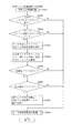
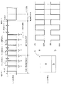
モータ制御用IC(モータドライバ)による役物用モータ229の制御の一例について、図88を参照して説明する。なお、説明を分かり易くするために、1ステップで90度回転する(即ち、4ステップで1周する)ステッピングモータを例に取って説明するが、実際の役物用モータ229は、1ステップの回転角度をより細かく設定できるように構成されている。具体的には、1ステップで1度回転するように構成されている。
An example of control of the
まず、図88(a)は、ステッピングモータで構成される役物用モータ229の概要を示す図である。この役物用モータ229は、対応するモータ制御用ICに対して音声ランプ制御装置113から励磁制御データを送ることにより、その励磁制御データに対応した部位が励磁されるように構成されている。具体的には、図88(a)に示す「A,B,C,D」に対応した4桁の2進数で構成された励磁制御データによって、モータ制御用ICにより励磁される。具体的には、役物用モータ229の各部位(即ち、A,B,C,Dのいずれか)に対応する励磁制御データが「1」であれば励磁され、励磁制御データが「0」であれば励磁されない。例えば、励磁制御のデータが「1100」であれば、A及びBが励磁され、CおよびDは励磁されない。この励磁制御データは、音声ランプ制御装置113のROM222に設けられている励磁テーブル(図88(b)参照)に規定されている。
First, FIG. 88 (a) is a diagram showing an outline of an
また、音声ランプ制御装置113には、励磁テーブル(図88(b)参照)に規定された複数の励磁制御データの中から1の励磁制御データを選択して設定するために用いられる励磁カウンタが設けられている。この励磁カウンタは、「0」を起点として正方向に1ずつ更新することができ、励磁カウンタの値が「3」となってから値が更新されると値が「0」に戻るループカウンタとなっている。この励磁カウンタ値が更新される度に、対応する励磁制御データが読み出されて設定される。励磁制御データが設定されると、励磁制御データに基づく各部位の励磁が即座に行われる(即ち、励磁制御データの設定からタイムラグなく役物用モータ229が動作する)。更に、励磁カウンタは、負の方向にも更新することができる。つまり、値が「0」を起点として、「0」→「3」→「2」→「1」→「0」の順番に更新することができる。負方向に更新する場合は、正方向に更新した場合と役物用モータ229の回転方向が逆向きになる。励磁カウンタを更新する方向(正方向であるか、負方向であるか)と、励磁カウンタの更新頻度とは、動作を設定する役物の種別毎に予め定められている。なお、この励磁カウンタの最大値は、役物用モータ229のステップ数に応じて変化する。具体的には、例えば、1ステップで1度回転する(即ち、モータが1回転するのに360ステップを要する)役物用モータ229の場合、励磁カウンタは「0」〜「359」の範囲で更新されるループカウンタとなる。
The sound
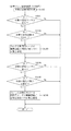
次いで、役物用モータ229の各部位を励磁するための励磁制御データの具体例について、図88(b)を参照して説明する。図88(b)は、励磁制御データを規定した励磁テーブルと、その励磁テーブルに規定された励磁制御データに基づいて励磁された役物用モータ229の状態との対応関係を示す図である。なお、図88(b)に示した通り、励磁テーブルには、励磁カウンタの値毎に励磁制御データが規定されている。
Next, a specific example of excitation control data for exciting each part of the
具体的には、図88(b)に示した通り、役物用モータ229に対応するシーケンスデータとして、励磁カウンタ「0」〜「3」の順に「1100,0110,0011,1001」の励磁制御データがそれぞれ規定されている。また、励磁カウンタ値「0」に対応するシーケンスデータである「1100」が設定されると、役物用モータ229のA、およびBの各位置が励磁される。また、励磁カウンタ値「1」に対応するシーケンスデータである「0110」が設定されると、役物用モータ229のB、およびCの各位置が励磁されるので、励磁カウンタ値が「0」の状態から時計回りに90度回転する。また、励磁カウンタ値「2」に対応するシーケンスデータである「0011」が設定されると、役物用モータ229のC、およびDの各位置が励磁され、励磁カウンタ値が「1」の状態から時計回りに90度回転する。また、励磁カウンタ値「3」に対応するシーケンスデータである「1001」が設定されると、役物用モータ229のA、およびDの各位置が励磁されるので、励磁カウンタ値が「2」の状態から時計回りに90度回転する。このように、図88に示した例では、励磁カウンタの値が正方向に1更新される毎に、役物用モータ229が時計回りに90度ずつ回転する。なお、上述した通り、励磁カウンタの値が負方向に更新される場合は、役物用モータ229が反時計回りに90度ずつ回転する。
Specifically, as shown in FIG. 88 (b), as the sequence data corresponding to the
このように、役物用モータ229の制御を、簡略化した動作モデルで説明したが、本実施形態で実際に用いられる役物用モータ229では、1ステップ毎に(即ち、励磁カウンタを1更新する毎に)1度ずつ回転させることができる。即ち、各役物を可変させる場合は、可変させるステップ数に応じた回数だけ励磁カウンタの値を1ずつ更新し、励磁カウンタの更新毎に励磁カウンタに対応する励磁制御データを設定することで、正確に各役物を可変させることができる。
As described above, the control of the
なお、各役物には、演出に応じた固有の動作パターンが設定されている。この動作パターンは、上述したモータ制御用IC(モータドライバ)に対して設定するコマンドを、経過時間毎に規定したものである。例えば、起立役物410の動作パターンとして、動作開始のタイミングとなってから、0.2秒が経過するまでの期間に、役物用モータ229を正方向へ10ステップだけ動作させることが規定されている。即ち、起立役物410の動作開始タイミングにおいて、モータドライバに対して動作ステップ数として10回を設定し、回転方向として正方向(張出位置へ向かう方向)を設定し、回転速度として20ms毎に1ステップ動作させる回転速度(0.2秒/10ステップ)を設定するためのコマンドを出力する動作パターンが規定されている。このコマンドに基づいて、モータドライバにより役物用モータ229が駆動され、動作開始から0.2秒経過時に10ステップ動作した状態となる。
Note that a unique operation pattern corresponding to the production is set for each accessory. This operation pattern defines a command to be set for the motor control IC (motor driver) described above for each elapsed time. For example, as an operation pattern of the standing
また、動作開始タイミングの0.2秒後〜1.8秒後までの1.6秒間においては、役物用モータ229を正方向へ160ステップ動作させることが規定されている。即ち、起立役物410の動作開始タイミングから0.2秒が経過した場合(即ち、ステップカウンタの値が10となった場合)に、モータドライバに対して動作ステップ数として160回を設定し、回転方向として正方向(張出位置へ向かう方向)を設定し、回転速度として10ms毎に1ステップ動作させる回転速度(1.6秒/160ステップ)を設定するためのコマンドを出力する動作パターンが規定されている。このコマンドに基づいて、モータドライバにより役物用モータ229が駆動され、動作開始から1.8秒経過時に170ステップ(160ステップ+0.2秒経過時までの10ステップ)動作した状態となる。
Further, for 1.6 seconds from 0.2 seconds to 1.8 seconds after the operation start timing, it is specified that the
また、動作開始タイミングの1.8秒後〜0.2秒後までの0.2秒間においては、役物用モータ229を正方向へ10ステップ動作させることが規定されている。即ち、起立役物410の動作開始タイミングから1.8秒が経過した場合(即ち、ステップカウンタの値が170となった場合)に、モータドライバに対して動作ステップ数として10回を設定し、回転方向として正方向(張出位置へ向かう方向)を設定し、回転速度として20ms毎に1ステップ動作させる回転速度(0.2秒/10ステップ)を設定するためのコマンドを出力する動作パターンが規定されている。このコマンドに基づいて、モータドライバにより役物用モータ229が駆動され、動作開始から2.0秒経過時に180ステップ(10ステップ+1.8秒経過時までの170ステップ)動作した状態となる。なお、この位置は起立役物410の張出位置(図8参照)に一致する。
Further, for 0.2 seconds from 1.8 seconds to 0.2 seconds after the operation start timing, it is specified that the
そして、2秒間の動作停止を設定するための停止コマンドが設定されるように動作パターンが規定されている。張出位置で2秒間停止させた後は、起立役物410を原点位置へ戻すための動作が実行されるように動作パターンが規定されている。具体的には、動作開始から4秒後に、動作ステップ数として10回を設定し、回転方向として負方向(原点位置へ向かう方向)を設定し、回転速度として20ms毎に1ステップ動作させる回転速度を設定するためのコマンドを出力する動作パターンが規定されている。これにより、0.2秒間かけて10ステップだけ原点位置側へ戻すことができる。
The operation pattern is defined so that a stop command for setting the operation stop for 2 seconds is set. After stopping for 2 seconds at the overhang position, an operation pattern is defined so that an operation for returning the standing
次いで、動作開始から4.2秒後(即ち、張出位置から原点位置へ向かう方向へ動作開始してから0.2秒後)に、動作ステップ数として160回を設定し、回転方向として負方向を設定し、回転速度として10ms毎に1ステップ動作させる回転速度を設定するためのコマンドを出力する動作パターンが規定されている。これにより、1.6秒間かけて160ステップだけ原点位置側へ戻すことができる。そして、動作開始から5.8秒後に、動作ステップ数として10回を設定し、回転方向として負方向を設定し、回転速度として10ms毎に1ステップ動作させる回転速度を設定するためのコマンドを出力する動作パターンが規定されている。これにより、原点位置まで戻すことができる。 Next, after 4.2 seconds from the start of the operation (that is, 0.2 seconds after the operation starts in the direction from the overhang position to the origin position), the operation step number is set to 160 times and the rotation direction is negative. An operation pattern for setting a direction and outputting a command for setting a rotation speed for one step operation every 10 ms as a rotation speed is defined. Thereby, it can return to the origin position side by 160 steps over 1.6 seconds. Then, after 5.8 seconds from the start of the operation, 10 times are set as the number of operation steps, a negative direction is set as the rotation direction, and a command for setting the rotation speed for one step operation every 10 ms is output as the rotation speed. The operation pattern is specified. Thereby, it can return to an origin position.
この動作パターンに従って動作させることにより、起立役物410を2秒間かけて張出位置へと動作させた後、張出位置で2秒間停止させ、その後2秒かけて原点位置へと戻すことができる。なお、動作速度(役物用モータ229の回転速度)を、動作開始直後や動作停止期間の経過後において他の期間に設定される回転速度よりも遅くしているのは、役物用モータ229を正常に励磁させるためである。即ち、停止していた役物用モータ229を動作開始させる場合に、回転速度が速すぎる(モータドライバより出力されるパルスの周波数が高すぎる)と、励磁制御データに基づいて役物用モータ229が励磁される前に次の励磁制御データに基づく励磁が開始されてしまう場合があり、励磁制御データの順番に役物用モータ229を励磁できなくなってしまう(脱調してしまう)場合がある。よって、役物用モータ229の動作開始時には、比較的遅い回転速度の設定とすることで、励磁制御データの出力間隔が短くなりすぎないようにし、役物用モータ229が脱調してしまうことを抑制している。
By operating according to this operation pattern, the standing
また、役物用モータ229を停止させる前(動作開始後1.8秒〜2秒の期間、および5.8秒〜6秒の期間)において、他の期間に設定される回転速度よりも遅くしているのは、役物用モータ229の回転を停止させるべきステップ数において確実に停止させるためである。即ち、回転速度を遅くし、励磁制御データの出力間隔を長くすることで、最後に励磁制御データが出力されてから、停止コマンドが出力されるまでの期間を長くすることができるので、停止コマンドをより確実に受信させることができる。よって、停止コマンドの受信漏れを防止し、定められたタイミングで確実に役物用モータ229の回転を停止させることができる。
In addition, before stopping the accessory motor 229 (a period of 1.8 seconds to 2 seconds and a period of 5.8 seconds to 6 seconds after the start of the operation), it is slower than the rotation speed set in other periods. The reason is that the rotation of the
なお、上述した通り、本実施形態の役物用モータ229は、1の励磁制御データが設定される毎にモータが1度ずつ回転するように構成されている。この1ステップの動作は、新たな励磁制御データが設定される度に、モータが瞬時に新たな設定で励磁されて、1度回転するように構成されている。この1ステップ(1度)の動作が開始されてから終了するまでの期間は、励磁制御データの設定間隔(励磁カウンタの更新間隔)によらず一定である。つまり、モータを1ステップ(1度)動作させるのに要する負荷電流(消費電力)は、励磁制御データの設定間隔によらず一定であるので、励磁制御データの設定間隔が長くなるほど1ステップ分の負荷電流(電力)を消費する頻度が低くなる。従って、役物用モータ229により消費される負荷電流(電力)も低くなる。よって、動作開始直後や動作停止期間の経過後、および動作停止前の期間において、役物用モータ229の回転速度を他の期間よりも遅くしておくことにより、これらの期間において負荷電流(消費電力)を低くすることができる。従って、1の役物の動作開始タイミングが、他の役物の動作停止タイミングの僅かに前(即ち、動作停止に向けて役物用モータ229の回転速度を遅くした状態)となった場合に、これらの役物を可変させるための役物用モータ229により消費される負荷電流(電力)が高くなりすぎることを抑制することができる。
As described above, the
このように、起立役物410を例に取って役物用モータ229の制御内容について説明したが、他の役物についても同様に、制御内容(モータドライバへ出力するコマンドの内容)が、役物の動作開始タイミングからの経過時間に対応付けて音声ランプ制御装置113のROM222に設けられているモータ制御コマンド設定テーブル(図示せず)に規定されている。また、動作パターンは、役物毎、および演出の種別毎にそれぞれ規定されている。役物の動作を設定する場合は、このモータ制御コマンド設定テーブル(図示せず)に規定されているコマンドを、モータ制御コマンド設定テーブルに規定されているタイミングで出力するだけで容易に各役物に対して予め定められている動作を設定することができる。
As described above, the control content of the
このように、本実施形態では、モータドライバに対してコマンドを設定することにより、コマンドで指定した回転速度、回転方向、および回転ステップ数で役物用モータ229を駆動させることができる。よって、役物を用いた多彩な演出動作を実現することができる。
Thus, in this embodiment, by setting a command to the motor driver, the
なお、本実施形態では、モータドライバに対して設定したコマンドに基づいて役物用モータ229が動作完了したか否かを、役物用モータ229が動作したステップ数に基づいて判断している。即ち、コマンドにより設定したステップ数と、モータドライバにより1ステップの動作が設定される度にモータドライバから出力される実行信号の受信回数とに基づいて、役物用モータ229に設定した動作が完了したか否かを判断しているが、これに限られるものではない。例えば、役物用モータ229を動作させるためのコマンドを設定してからの経過時間を計測し、その経過時間に基づいて役物用モータ229の動作が完了したか否かを判別するように構成してもよい。
In the present embodiment, whether or not the operation of the
音声ランプ制御装置113は、枠ボタン228からの入力を監視し、遊技者によって枠ボタン228が操作された場合は、第3図柄表示装置81で表示されるステージを変更したり、スーパーリーチ時の演出内容を変更したりするように、音声出力装置226、ランプ表示装置227を制御し、また、表示制御装置114へ指示する。ステージが変更される場合は、変更後のステージに応じた背面画像を第3図柄表示装置81に表示させるべく、変更後のステージに関する情報を含めた背面画像変更コマンドを表示制御装置114へ送信する。ここで、背面画像とは、第3図柄表示装置81に表示させる主要な画像である第3図柄の背面側に表示される画像のことである。
The sound
音声ランプ制御装置113は、主制御装置110からのコマンドや、音声ランプ制御装置113に接続された各種装置等の状況に応じてエラーを判定し、そのエラーの種別を含めてエラーコマンドを表示制御装置114へ送信する。表示制御装置114では、受信したエラーコマンドによって示されるエラー種別(例えば、役物の動作エラーや振動エラー等)に応じたエラーメッセージ画像を第3図柄表示装置81に遅滞無く表示させる制御が行われる。
The sound
音声ランプ制御装置113のROM222には、変動パターンテーブル222aと、動作開始条件テーブル222bと、負荷基準値テーブル222cと、電源復帰動作テーブル222dと、役物動作設定テーブル222eとが少なくとも規定されている。
In the
変動パターンテーブル222aは、主制御装置110から変動パターンコマンドにより通知された大まかな変動演出(変動表示)の態様に基づいて、変動演出(変動表示)の詳細な態様を選択するために参照されるテーブルである。この変動パターンテーブル222aから選択された変動演出の態様に基づいて、表示用変動パターンコマンドが設定される(図43のS1704参照)。
The variation pattern table 222a is referred to in order to select a detailed aspect of the variation effect (variation display) based on the rough variation effect (variation display) aspect notified by the variation pattern command from the
動作開始条件テーブル222bは、各役物を動作開始させる場合の動作開始条件を規定したデータテーブルである。この動作開始条件テーブル222bには、1又は複数の役物で構成されたグループ単位での動作開始条件がそれぞれ規定されている。この動作開始条件に従って各グループを動作させることにより、役物同士が干渉(接触)することなく各役物を可変させることができる。 The operation start condition table 222b is a data table that defines the operation start conditions when starting the operation of each accessory. In the operation start condition table 222b, operation start conditions are defined for each group composed of one or more accessories. By operating each group according to this operation start condition, it is possible to vary each accessory without interference (contact) between the actors.
ここで、グループとは、構成する役物を同時に可変させたとしても、互いに干渉し合わない1又は複数の役物の集合を指す。本実施形態のパチンコ機10では、グループ1〜グループ5までの5つのグループが設けられている。本実施形態のパチンコ機10では、役物を動作させる場合は原則としてグループ単位で予め定められた動作を行うように構成され、グループ単独で動作させたり、複数のグループを同時に(複合的に)動作させたりすることにより、多種多様な演出を実現することができる。このグループ毎に予め定められた動作は、音声ランプ制御装置113のROM222に規定されており、各グループの動作開始時にROM222から動作内容を読み出して設定するように構成されている。
Here, the group refers to a set of one or more actors that do not interfere with each other even if the constituents to be configured are changed at the same time. In the
なお、グループ1は、第2スライド動作ユニットに設けられた各役物によって構成されている。このグループ1は、動作条件が成立すると、各スライド役物810,820,830,840を原点位置(図5参照)から張出位置(図10参照)まで動作させた後、原点位置(図5参照)に戻すという一連の動作が実行される。グループ2は、第1スライド動作ユニット500に設けられた各役物によって構成され、動作条件が成立すると、回動軸520を回転軸として回動役物520を時計回りに回動させながら、傾倒役物510を張出位置(図11参照)まで動作させた後、回動役物520を反時計回りに回動させながら、傾倒役物510を原点位置(図5参照)に戻すという一連の動作が実行される。
Note that the
グループ3は、揺動動作ユニット400に設けられた各役物によって構成され、グループ3の動作条件が成立すると、起立役物410を張出位置(図8参照)まで動作させた後、起立役物410を原点位置(図5参照)に戻すという一連の動作が実行される。グループ4は、装飾役物ユニット700に設けられた役物のうち、右側揺動役物710、および左側揺動役物730によって構成され、動作条件が成立すると、右側揺動役物710、および左側揺動役物730が原点位置(図5参照)において揺動動作を行った後、原点位置(図5参照)において動作停止するという一連の動作が実行される。
The
グループ5は、装飾役物ユニット700に設けられた役物のうち、中央揺動役物720によって構成され、演出に応じて2種類の動作を実行可能に構成されている。具体的には、原点位置(図5参照)において揺動動作を行った後、原点位置(図5参照)において動作停止する一連の動作と、原点位置(図5参照)から張出位置(図13参照)へと降下動作した後、原点位置(図5参照)に戻すという一連の動作とを実行可能に構成されている。
The
このように、本実施形態では、複数のグループを設けておき、グループ毎に予め定められた動作を行うように構成している。これにより、1のグループを単独で動作させたり、複数のグループを同時に(複合的に)動作させたりすることができるので、多種多様な演出を実現することができる。また、複数の役物の動作を一つ一つ独立して設定するように構成してしまうと、動作条件が複雑となってしまう。即ち、変動演出を開始する際や、演出の途中等の役物の動作開始タイミングにおいて、役物一つ一つを動作開始させるか否か判別し、更に、動作開始させる役物に対応する動作をそれぞれ設定する必要がある。これに対して、本実施形態のようにグループを規定していれば、動作させるグループを選択し、選択したグループに対して予め定められた動作を設定するという単純な処理を実行するだけで、各役物を適切に動作させることができる。よって、音声ランプ制御装置113のMPU221の処理負荷を軽減することができる。
Thus, in the present embodiment, a plurality of groups are provided, and a predetermined operation is performed for each group. Thereby, one group can be operated independently, or a plurality of groups can be operated simultaneously (composite), so that a wide variety of effects can be realized. Moreover, if it is configured so that the actions of a plurality of actors are set independently one by one, the operation condition becomes complicated. That is, it is determined whether or not to start each of the actors at the start timing of the action, such as during the stage of the production, or in the middle of the production. Must be set individually. On the other hand, if a group is defined as in the present embodiment, simply select a group to be operated, and execute a simple process of setting a predetermined operation for the selected group. Each accessory can be operated appropriately. Therefore, the processing load on the
なお、装飾役物ユニット700を構成する各揺動役物710,720,730のうち、中央揺動役物720のみ異なるグループ(グループ5)としているのは、他の揺動役物710,730が他のユニットに含まれる役物と干渉する虞がないのに対して、中央揺動役物720は、張出位置まで降下動作した場合に他の役物(起立役物410や、傾倒役物510)と干渉する虞があるためである。つまり、装飾役物ユニット700を構成する全ての役物を同一のグループとしてしまうと、中央揺動役物720が他の役物と干渉しないタイミングで動作させなければならないので、左側揺動役物710、および右側揺動役物730の動作を制限する結果となるためである。これを防止するために、本実施形態では、中央揺動役物720を左側揺動役物710、および右側揺動役物730と異なるグループとし、左側揺動役物710、および右側揺動役物730の動作の自由度を高めている。
Note that among the swinging
図17(a)を参照して、上述の動作開始条件テーブル222bについて詳しく説明する。図17(a)は、動作開始条件テーブル222bの規定内容を示した図である。図17(a)に示した通り、動作開始条件テーブル222bには、グループ毎の動作開始条件が規定されている。具体的には、グループ2の動作条件として、グループ3、およびグループ5を構成する役物が共に原点位置であることが規定されている。これは、グループ3に含まれる起立役物410、又はグループ5に含まれる中央揺動役物720が張出位置に動作した状態でグループ2に含まれる傾倒役物510が張出位置へと動作した場合に、起立役物410、又は中央揺動役物720に衝突する虞があるためである。
With reference to FIG. 17A, the above-described operation start condition table 222b will be described in detail. FIG. 17A is a diagram showing the specified contents of the operation start condition table 222b. As shown in FIG. 17A, the operation start condition table 222b defines an operation start condition for each group. Specifically, it is specified as an operation condition of
また、グループ3の動作条件として、グループ2、およびグループ5を構成する役物が共に原点位置であることが規定されている。これは、グループ2に含まれる傾倒部剤510、又はグループ5に含まれる中央揺動役物720が張出位置に動作した状態でグループ3に含まれる起立役物410が張出位置へと動作した場合に、傾倒役物510、又は中央揺動役物720に衝突する虞があるためである。
In addition, as an operating condition of
更に、グループ5の動作条件として、グループ2、およびグループ3を構成する役物が共に原点位置であることが規定されている。これは、グループ2に含まれる傾倒役物510、又はグループ3に含まれる起立役物410が張出位置に動作した状態でグループ5に含まれる中央揺動役物720が張出位置へと動作した場合に、傾倒役物510、又は起立役物410に衝突する虞があるためである。
Furthermore, as an operating condition of
一方、グループ1、およびグループ4については、動作開始条件が規定されていない。これは、グループ1を構成する各スライド役物810,820,830,840、およびグループ5を構成する右側揺動役物710、および左側揺動役物730がどのような配置であっても、他の役物の動作に干渉する虞がない位置関係となるためである。
On the other hand, for
このように、本実施形態のパチンコ機10では、グループ単位で役物の動作条件を設定することにより、異なるグループの役物同士が干渉し合うことを抑制している。これにより、役物同士が衝突し、その衝突の衝撃で役物が破損してしまうことを防止できる。また、役物の動作が他の役物により妨げられることにより、役物の動作と第3図柄表示装置81に表示される表示演出の内容とがずれてしまい、遊技者に対して違和感を与えてしまうことを抑制することができる。また、役物一つ一つに対して動作条件を設定するのでなく、グループ単位で動作条件を設定すればよいので、設計を簡素化することができる。よって、設計時において、役物の動作設定を行う設計者の手間を削減することができる。また、グループ単位での動作条件を設定するテーブルを用意すればよく、役物一つ一つに対して動作条件を設定するためのデータテーブルを用意する必要がなく、グループ単位の動作条件を規定すればよいので、動作開始条件テーブル222bのデータ量を削減することができる。よって、記憶領域の削減によりパチンコ機10の低価格化を図ることができる。
As described above, in the
本実施形態では、5つのグループを設けているが、これに限られるものではなく、グループを少なくし、例えば、3つのグループで構成してもよい。これにより、データテーブルのデータ量を更に削減することができる。また、グループを増やして、例えば、7つのグループで構成してもよい。これにより、役物の動作をより細かく設定することができるので、演出動作の自由度を高めることができる。よって、遊技者の遊技に対する興趣を向上させることができる。 In the present embodiment, five groups are provided, but the present invention is not limited to this, and the number of groups may be reduced, and for example, three groups may be configured. Thereby, the data amount of the data table can be further reduced. Further, the number of groups may be increased, and for example, seven groups may be configured. Thereby, since operation | movement of an accessory can be set more finely, the freedom degree of production operation | movement can be raised. Therefore, the interest in the game of the player can be improved.
負荷基準値テーブル222bは、各役物用モータ229を駆動させるための負荷電流(消費電力)に対応する値(駆動負荷基準値)を役物毎に規定しているデータテーブルである。本実施形態のパチンコ機10では、この負荷基準値テーブル222bに基づいて、駆動する役物に対応する役物用モータ229によって消費される負荷電流(電力)の合計値が電流容量(定格電力)を上回るか(駆動負荷基準値の合計が100を超える)否かを判別する。そして、電流容量(定格電力)を上回る負荷電流(電力)が消費されると判別された場合は、新たに駆動させようとする役物の駆動をキャンセルするように構成されている。
The load reference value table 222b is a data table that defines a value (drive load reference value) corresponding to a load current (power consumption) for driving each
この負荷基準値テーブル222cの詳細について、図17(b)を参照して説明する。図17(b)は、この負荷基準値テーブル222cの規定内容を示した図である。図17(b)に示した通り、負荷基準値テーブル222c(図17(b)参照)には、グループを構成する役物毎に駆動負荷基準値(電流容量(定格電力)に対する負荷電流(消費電力)の割合)が規定されている。 Details of the load reference value table 222c will be described with reference to FIG. FIG. 17B is a diagram showing the specified contents of the load reference value table 222c. As shown in FIG. 17 (b), the load reference value table 222c (see FIG. 17 (b)) shows the load current (consumption for the drive load reference value (current capacity (rated power)) for each accessory constituting the group. The ratio of power) is specified.
具体的には、第2スライド動作ユニット800(グループ1)の各スライド役物810,820,830,840に対応する役物用モータ229を駆動させた場合の駆動負荷基準値は、いずれも15である。即ち、各スライド役物810,820,830,840に対応する役物用モータ229を駆動させると、それぞれ駆動負荷基準値15に相当する負荷電流(電力)が消費される。よって、第2スライド動作ユニット800(グループ1)の各スライド役物810,820,830,840を同時に可変させた場合は(図10参照)、駆動負荷基準値60(15×4)に相当する負荷電流(電力)が消費される。このため、グループ1の全ての役物を同時に可変させたとしても、電流容量(定格電力)に対して駆動負荷基準値換算で40の余裕があるので、電流容量(定格電力)の範囲内において、他のグループの役物と同時に動作させることができる。
Specifically, the drive load reference values when the
また、第1スライド動作ユニット500(グループ2)の傾倒役物510に対応する役物用モータ229を駆動させた場合の駆動負荷基準値は30であり、回動役物520に対応する役物用モータ229を駆動させた場合の駆動負荷基準値は10である。よって、グループ2を構成する役物を同時に可変させた場合、駆動負荷基準値40(30+10)に相当する負荷電流(電力)が消費される。なお、回動役物520は、回動軸520aを回転軸として時計回り、および反時計回りに回動させることができるが、どちらの方向に回転させたとしても駆動負荷基準値は同一(10)である。
The driving load reference value when the
グループ3は、揺動動作ユニット400の起立役物410のみから構成されている。この起立役物410に対応する駆動負荷基準値は15であり、起立役物410に対応する役物用モータ229を駆動させることにより、駆動負荷基準値が15に相当する負荷電流(電力)が消費される。
グループ4は、装飾役物ユニット700を構成する役物のうち、左側揺動役物710と、右側揺動役物730とにより構成されている。図17に示した通り、これらに対応する負荷基準値はいずれも10であり、各揺動役物710,730に対応する役物用モータ229を駆動させることにより、駆動負荷基準値が10に相当する負荷電流(電力)が消費される。
The
グループ5は、装飾役物ユニット700の中央揺動役物720のみから構成されている。この中央揺動役物720に対応する駆動負荷基準値は15であり、中央揺動役物720に対応する役物用モータ229を駆動させることにより、駆動負荷基準値が15に相当する負荷電流(電力)が消費される。
The
本実施形態では、この負荷基準値テーブル222c(図17(b)参照)に規定された駆動負荷基準値に基づき、可変中の役物、および新たに可変させる役物に対応する役物用モータ229の負荷電流(消費電力)の合計が電流容量以下(定格電力以下)となるように制御する。より具体的には、駆動中の役物用モータ229に対応する駆動負荷基準値と、新たに可変させる役物に対応する役物用モータ229の駆動負荷基準値とを加算し、合計が100を超えるか否かを判別する。そして、100を超える(即ち、新たに役物を可変させることにより電流容量(定格電力)を上回る負荷電流(電力)が消費されてしまう)と判別した場合は、新たに可変させようとしていた役物の動作を停止させるように構成されている。
In this embodiment, based on the drive load reference value defined in the load reference value table 222c (see FIG. 17B), the accessory motor corresponding to the accessory being changed and the accessory to be newly changed. Control is performed so that the total of the load current (power consumption) of 229 is equal to or less than the current capacity (less than the rated power). More specifically, the driving load reference value corresponding to the driving
ここで、従来は、近年の遊技機に比較して役物の種類が少なく、役物を自由に動作させたとしても、電流容量(定格電力)を上回る負荷電流(電力)を消費してしまうことはなかった。しかしながら、近年、遊技機に搭載される役物の数や種類が増加傾向にあり、役物を動作させることで消費される負荷電流(電力)も増加してきている。よって、複数の役物を同時に動作させた場合等に、電流容量(定格電力)を上回る負荷電流(電力)が消費されてしまう場合がある。かかる場合には、電源装置のスペックを超えてしまう結果、役物の制御を行う制御装置がシャットダウンしてしまったり、遊技機自体の電源が落ちてしまったり、役物の動作異常が発生してしまったりするという不具合が生じる虞があった。 Here, conventionally, there are few kinds of accessories compared with recent gaming machines, and even if the accessories are operated freely, a load current (power) exceeding the current capacity (rated power) is consumed. It never happened. However, in recent years, the number and types of accessories mounted on gaming machines have been increasing, and the load current (electric power) consumed by operating the accessories has also increased. Therefore, when a plurality of objects are operated simultaneously, the load current (power) exceeding the current capacity (rated power) may be consumed. In such a case, as a result of exceeding the specifications of the power supply device, the control device for controlling the accessory may shut down, the gaming machine itself may be turned off, or an operation abnormality of the accessory may occur. There was a possibility that a problem of stagnation would occur.
これに対して本実施形態のパチンコ機10では、上述した通り、電流容量(定格電力)を上回る負荷電流(電力)が消費されると判別した場合に、新たに動作させようとしていた役物の動作をキャンセルするように構成されているので、役物用モータ229を常に電流容量以下(定格電力以下)の負荷電流(消費電力)の範囲内で駆動させることができる。即ち、負荷電流(消費電力)が電流容量(定格電力)を超過してしまうことを抑制することができる。よって、電流容量(定格電力)を超過することにより、役物用モータ229を制御する音声ランプ制御装置113がシャットダウンしてしまったり、パチンコ機10の電源が落ちてしまったり、役物の動作異常が発生してしまったりすることを抑制することができる。
On the other hand, in the
また、本実施形態では、電流容量を超えないようにするために、各役物用モータ229に対して動作条件を詳細に設定するのでなく、単に役物用モータ229を新たに駆動させようとする場合に、駆動負荷基準値が所定の値(100)を上回るか否かを判別し、役物用モータ229を新たに駆動させるか否かを決定するように構成している。即ち、比較的単純な処理によって電流容量以下の範囲での役物用モータ229の駆動を実現している。よって、パチンコ機10の設計者は、プログラムにおいて単純な判別処理を記述しておくだけでよく、各役物を可変させる条件をデータテーブル等に詳細に規定しておく必要がないので、設計者の作業量を削減することができる。また、データテーブル等のデータ量を削減することができるので、記憶容量を削減することにより、パチンコ機10の原価を低減することができる。
In the present embodiment, in order not to exceed the current capacity, the operating conditions are not set in detail for each
本実施形態の負荷基準値テーブル222cでは、各役物に対応する負荷基準値が1種類のみ規定されているが、これに限られるものではない。また、例えば、各役物用モータ229を通常の速度で回転させた場合(役物用モータ229の各動作ステップを通常の時間間隔毎に設定した場合)における駆動負荷基準値と、通常よりも遅い速度で回転させた場合(役物用モータ229の各動作ステップを通常よりも長い時間間隔毎に設定した場合)における駆動負荷基準値との2種類を設けておいてもよい。この場合において、通常の速度に設定した場合の駆動負荷基準値の合計が100を超える場合には、通常よりも遅い速度でモータを回転させることにより、駆動負荷基準値の合計が100以下となるように制御してもよい。役物用モータ229の動作ステップ間隔を長くすると、役物用モータ229により消費される負荷電流(電力)の平均値が少なくなるので、駆動負荷基準値も小さな値とすることができる。
In the load reference value table 222c of the present embodiment, only one type of load reference value corresponding to each accessory is defined, but the present invention is not limited to this. In addition, for example, when each
また、役物の動作パターンとして、動作の途中で動作速度が変化する(即ち、モータの回転速度が変化する)ように構成し、動作速度毎の駆動負荷基準値を規定しておいてもよい。例えば、各役物を動作開始後1秒以内、および動作終了前1秒以内には他の動作期間(通常速度用の動作期間)よりも役物制御用モータ229を低速で動作させるように構成し、低速用の駆動負荷基準値と通常速度用の駆動負荷基準値とを規定しておくように構成してもよい。これにより、例えば、1の役物の動作開始タイミングが、他の役物の動作終了前1秒以内であったときに、通常速度用でなく、低速用の駆動負荷基準値を参照することができるので、動作開始させることにより電流容量(定格電力)を超える虞があるか否かをより正確に判別することができる。
Further, the operation pattern of the accessory may be configured such that the operation speed changes during the operation (that is, the motor rotation speed changes), and the drive load reference value for each operation speed may be defined. . For example, each accessory is configured to operate the
電源復帰動作テーブル222dは、電源投入時において各役物を正常に可変させることができるか否かを確認するための電源復帰動作を実行する際に参照されるデータテーブルである。電源復帰動作は、電源が投入される度に(RAM消去スイッチ122が押下されたか否かに関わらず)実行される。この電源復帰動作テーブル222dには、復帰ポインタ223fの値に対応付けて、役物の種別毎の復帰動作が規定されている。復帰動作によっていずれかの役物の動作に異常が生じていると判別された場合は、エラーコマンドが設定される(図41のS1503参照)。このエラーコマンドには、異常の種別や、異常発生個所を示す情報が含まれる。このエラーコマンドを受信した表示制御装置114は、第3図柄表示装置81に対して、異常の種別や異常個所を示す表示を行う。このように、電源投入に基づいて復帰動作を行うことにより、各役物に異常が発生しているか否かを、迅速に把握することができる。よって、ホールの店員がパチンコ機10の役物に異常が発生していることに気付かないまま、遊技者に対して遊技を開始させてしまうことを抑制することができる。
The power recovery operation table 222d is a data table that is referred to when performing a power recovery operation for confirming whether or not each accessory can be normally varied when the power is turned on. The power recovery operation is executed every time the power is turned on (regardless of whether or not the RAM erase
なお、本実施形態のパチンコ機10では、電源復帰動作テーブル222dに基づいて電源復帰動作を実行する前に、全ての役物を原点位置に復帰(原点復帰)させるように構成されている。つまり、役物の可変途中で電源が遮断された場合には、電源投入に基づいて原点復帰を行った後に電源復帰動作を実行するように構成されている。これにより、電源復帰動作は原点位置を起点として開始される動作の1通りのみを用意しておけばよい(電源投入時の役物の配置に応じて異なるパターンの電源復帰動作を規定する必要がない)ので、電源復帰動作テーブル222dのデータ量を削減することができる。
Note that the
なお、役物の可変途中に電源が遮断され、電源が再度投入された場合に、役物の動作の続きから実行させないのは、音声ランプ制御装置113のRAM223がバックアップされていないからである。即ち、一旦電源が遮断されると、それまでに行われていた演出の進行具合を把握不可能になってしまうからである。よって、RAM消去スイッチ122が押下されたか否かに関わらず、電源が投入された場合は、原点復帰動作を実行した上で、電源復帰動作を行うように構成されている。なお、電源の遮断時に演出の途中であった場合は、電源が復帰してから、少なくとも演出期間が経過するまでは、簡易的な表示演出が実行されるように構成されている。この簡易的な表示演出(後述する、電源投入時画像を用いた演出)は、演出の進行度合によらず、演出の終了時間まで同じ演出が繰り返されるように構成されているので、電源遮断時の演出の進行具合を必要とすることなく、即座に演出を表示させることができる。よって、電源が投入してから、演出期間が経過するまで第3図柄表示装置81に対して何らの演出も表示されないことにより、遊技者に対して不安感を抱かせてしまうことを抑制することができる。
The reason why the operation of the accessory is not continued when the power is cut off during the variable of the accessory and the power is turned on again is because the
本実施形態では、RAM223の記憶内容がバックアップされていないが、バックアップ電力を供給し、電源が遮断された後もRAM223に記憶された情報を保持可能に構成してもよい。これにより、演出途中で電源が遮断された場合は、電源投入後に電源断時点の演出の進行具合を判別して、演出を続きから実行させることができるので、遊技者の遊技に対する興趣を向上させることができる。
In the present embodiment, the storage contents of the
電源復帰動作テーブル222dの詳細について、図18を参照して説明を行う。図18は、電源復帰動作テーブル222dの一例を示す図である。図18に示した通り、電源復帰動作テーブル222dには、復帰ポインタ223fの値毎に、役物の動作内容が規定されている。なお、詳細については後述するが、復帰ポインタ223fは、復帰動作が終了するまで、音声ランプ制御装置113のメイン処理(図39参照)が実行される毎に、初期動作処理(図41参照)の中で1ずつ更新される。
Details of the power recovery operation table 222d will be described with reference to FIG. FIG. 18 is a diagram illustrating an example of the power recovery operation table 222d. As shown in FIG. 18, in the power return operation table 222d, the operation content of the accessory is defined for each value of the
図18に示した通り、本実施形態の電源復帰動作テーブル222d(図18参照)
は、復帰ポインタ223fの更新に従って、グループ1→グループ2→グループ3→グループ4→グループ5の順番に復帰動作が実行されるように構成されている。また、復帰動作では、各役物を原点位置から張出位置まで可変させた後、原点位置まで戻すように可変させるように構成されている。即ち、通常遊技中に役物が可変する可能性のある全動作範囲を、復帰動作により網羅的に動作させる。これにより、いずれかの役物に異常が発生している場合に、確実にその異常を検出することができる。
As shown in FIG. 18, the power recovery operation table 222d of this embodiment (see FIG. 18).
Is configured so that the return operation is executed in the order of
また、本実施形態の電源復帰動作テーブル222dでは、各役物を張出位置まで可変させてから、所定期間(2000ms)だけ動作停止させるように構成されている。これにより、張出位置までの動作、および張出位置から原点位置までの動作の中で異常が発生するか否かを検出できることに加えて、動作停止中に異常が発生するか否かを検出することができる。なお、動作停止中の異常とは、例えば、動作停止を設定したにも関わらず、動作が停止しなかった場合や、動作停止期間として指定された所定期間(2000ms)が経過する前に、原点位置へ戻ってしまう場合、動作停止期間が経過しても原点位置への戻り動作が開始されない場合等である。 Further, the power recovery operation table 222d of the present embodiment is configured to stop the operation for a predetermined period (2000 ms) after changing each accessory to the overhang position. As a result, it is possible to detect whether or not an abnormality occurs during the operation up to the overhang position and the operation from the overhang position to the origin position, and also detect whether or not an abnormality occurs during the operation stop. can do. Note that an abnormality during operation stop means, for example, when the operation is not stopped even though the operation stop is set, or before the predetermined period (2000 ms) designated as the operation stop period elapses. For example, when returning to the position, the return operation to the origin position is not started even after the operation stop period has elapsed.
更に、本実施形態の電源復帰動作テーブル222dでは、グループ1〜グループ5までの全ての役物の復帰動作が終了した後で、所定期間(2000ms)の動作停止期間を設定するように構成されている。この停止期間は、出荷検査等で、音声ランプ制御装置113等のサブ側の制御装置が正常に立ち上がるか否かを確認する場合に、確認を終了してパチンコ機10の電源を遮断するタイミングとして設けられている。即ち、復帰動作の終了後に役物が即座に動作してしまうと、パチンコ機10の検査者は、その動作した役物が原点に復帰するまで待ってから電源を遮断するか、役物の動作中に電源を遮断し、電源の遮断後に役物を手動で原点位置まで戻さなければならず、検査効率が悪化してしまう虞がある。これに対して、本実施形態のように、復帰動作終了後に動作停止期間を設けることにより、動作停止期間中に電源を遮断すれば、全ての役物が原点位置にある状態で電源が遮断された状態とすることができる。よって、原点位置へ復帰するまで待機したり、電源の遮断後に手動で役物を原点位置へと復帰させたりする必要がないので、出荷検査等の検査効率を向上させることができる。
Furthermore, the power recovery operation table 222d of the present embodiment is configured to set an operation stop period of a predetermined period (2000 ms) after the recovery operation of all the objects from
図14に戻って説明を続ける。役物動作設定テーブル222eは、パチンコ機10の各種演出において、動作させる役物の種別(グループ)と、動作タイミングとを規定したデータテーブルである。本実施形態では、この役物動作設定テーブル222eに基づいて、役物の動作が設定される。
Returning to FIG. 14, the description will be continued. The accessory operation setting table 222e is a data table that defines the type (group) of the accessory to be operated and the operation timing in various effects of the
この役物動作設定テーブル222eの詳細について、図19を参照して説明する。図19は、役物動作設定テーブル222eの規定内容を示した図である。図19に示した通り、役物動作設定テーブル222eには、対応する演出毎に、役物を動作させるタイミングと、その動作タイミングにおいて動作させる役物のグループとが規定されている。 Details of the accessory operation setting table 222e will be described with reference to FIG. FIG. 19 is a diagram showing the specified contents of the accessory operation setting table 222e. As shown in FIG. 19, the accessory operation setting table 222 e defines the timing for operating an accessory and the group of actors operated at the operation timing for each corresponding effect.
具体的には、演出時間が5秒間のオープニング演出では、役物の動作タイミングが演出開始時に設定されており、動作タイミングにおいて動作させる役物のグループは、グループ1である旨が規定されている。即ち、オープニング演出の開始にあわせて、各スライド役物810,820,830,840を動作させることが規定されている。なお、上述した通り、グループ1の動作条件が成立すると、各スライド役物810,820,830,840を原点位置(図5参照)から張出位置(図10参照)まで動作させた後、原点位置(図5参照)に戻すという一連の動作が実行される。また、上述した通り、この一連の動作を設定するための制御内容(経過時間毎にモータドライバに対して出力するコマンド)は、モータ制御コマンド設定テーブル(図示なし)に規定されている。
Specifically, in the opening effect with a production time of 5 seconds, the action timing of the accessory is set at the start of the effect, and it is specified that the group of the actors to be operated at the operation timing is
また、演出時間が20秒間の外れスーパーリーチ演出、および共用スーパーリーチ演出では、演出開始から8秒が経過したタイミングで、グループ4、およびグループ5の役物を揺動動作させる旨が規定されている。なお、上述した通り、グループ4の動作条件が成立すると、右側揺動役物710、および左側揺動役物730が原点位置(図5参照)において揺動動作を行った後、原点位置(図5参照)において動作停止するという一連の動作が実行され、グループ5において揺動動作の動作条件が成立すると、中央揺動役物720が原点位置(図5参照)において揺動動作を行った後、原点位置(図5参照)において動作停止する一連の動作が実行される。
In addition, in the super-reaching effect and the shared super-reaching effect with a production time of 20 seconds, it is specified that the
加えて、外れスーパーリーチ演出、および共用スーパーリーチ演出では、演出開始から15秒が経過したタイミングで、グループ2の役物を動作させる旨が規定されている。なお、上述した通り、グループ2の動作条件が成立すると、回動軸520を回転軸として回動役物520を時計回りに回動させながら、傾倒役物510を張出位置(図11参照)まで動作させた後、回動役物520を反時計回りに回動させながら、傾倒役物510を原点位置(図5参照)に戻すという一連の動作が実行される。異なるタイミングで異なる役物を動作させることにより、遊技者の大当たりに対する期待感をより向上させることができる。
In addition, in the outlier super reach production and the shared super reach production, it is defined that the actors in
また、演出時間が30秒間の外れスペシャルリーチA、および共用スペシャルリーチAでは、演出開始から8秒が経過したタイミングで、グループ3の役物を動作させる旨が規定されている。なお、上述した通り、グループ3の動作条件が成立すると、起立役物410を張出位置(図8参照)まで動作させた後、起立役物410を原点位置(図5参照)に戻すという一連の動作が実行される。
In addition, in the special reach A with a production time of 30 seconds off and the shared special reach A, it is defined that the actors of the
その後、演出開始から15秒が経過したタイミングで、グループ2の役物を動作させる旨が規定され、演出開始から25秒が経過したタイミングで、グループ1、およびグループ3の役物を動作させる(即ち、図12に示す状態となるように動作させる)旨が規定されている。多くの役物が動作するほど、演出の見た目が派手となり、遊技者の大当たりに対する期待感を向上させることができる。よって、演出の終盤に複数のグループ(グループ1、およびグループ3)を複合的に動作させることにより、遊技者の期待感を演出が進むにつれて盛り上げることができる。従って、遊技者の遊技に対する興趣を向上させることができる。
After that, it is defined that the actors of
また、演出時間が30秒の外れスペシャルリーチB、共用スペシャルリーチBでは、演出開始から8秒が経過したタイミングで、グループ1、およびグループ2の役物を動作させる(即ち、図11に示す状態に動作させる)旨が規定されている。また、演出開始から15秒が経過したタイミングで、グループ3の役物を動作させる旨が規定され、演出開始から25秒が経過したタイミングで、グループ1、およびグループ3の役物を動作させる旨が規定されている。外れスペシャルリーチA、共用スペシャルリーチAとは異なる役物の動作パターンとすることにより、同じ演出期間であっても、異なる態様の演出を実行することができる。よって、演出を多様化させることができる。
Further, in the special reach B where the production time is off by 30 seconds and the shared special reach B, the actors of the
また、演出期間が30秒であり、大当たりAに当選した場合にのみ選択されるスペシャルリーチでは、演出開始から8秒が経過したタイミングで、グループ1、およびグループ2の役物を動作させる(即ち、図11に示す状態に動作させる)旨が規定されている。また、演出開始から15秒が経過したタイミングで、グループ3の役物を動作させる旨が規定され、演出開始から25秒が経過したタイミングで、グループ1の役物を動作させ、且つ、グループ5の役物を降下動作させる(即ち、図13に示す状態に動作させる)旨が規定されている。
Further, in the special reach that is selected only when the production period is 30 seconds and the jackpot A is won, the actors of
つまり、演出開始から25秒が経過するまでは、役物の動作パターンが外れスペシャルリーチB、共用スペシャルリーチBと同一であり、演出開始から25秒以降の動作のみが異なっている。よって、25秒が経過する前に、外れスペシャルリーチBであるか、共用スペシャルリーチであるか、スペシャルリーチであるかを役物の動作から区別することが困難とすることができる。従って、演出の終盤である25秒以降まで、遊技者に対して当たりとなるか外れとなるかを興味深く見守らせることができる。また、25秒経過時にグループ5の役物が降下動作することにより、遊技者に対して今回の演出がスペシャルリーチであったこと(即ち、変動演出の終了後に、大当たりAとなること)を認識させることができる。よって、演出が終了するよりも前に大当たりとなることを認識した遊技者に対して、残りの演出期間において、大当たりとなることに対する満足感と、大当たりが確定する役物動作を発生したことに対する達成感とを抱かせることができる。
In other words, until 25 seconds have passed since the start of the production, the action pattern of the accessory has been removed and is the same as that of the special reach B and the shared special reach B, and only the operation after 25 seconds from the start of the production is different. Therefore, before 25 seconds elapses, it can be difficult to distinguish whether it is out-of-order special reach B, shared special reach, or special reach from the action of the accessory. Therefore, it can be interestingly watched whether the player wins or misses until 25 seconds after the final stage of the production. In addition, when the actors of
このように、本実施形態では、役物動作設定テーブル222eに役物の動作タイミングと、動作させる役物のグループとが規定されているので、この役物動作設定テーブル222eに基づいて各グループに対してあらかじめ定められている動作を実行するだけで、多種多様な役物の動作を実現することができる。 Thus, in this embodiment, since the operation timing of the accessory and the group of the accessory to be operated are defined in the accessory operation setting table 222e, each group is assigned to each group based on the accessory operation setting table 222e. On the other hand, it is possible to realize various actions of the actors simply by executing a predetermined action.
また、本実施形態では、全ての変動演出において役物の動作を行わせるのでなく、比較的変動時間の長い一部の変動演出でのみ役物の動作が設定されるように構成されている。比較的変動時間の長い変動演出は、外れを報知するための演出として選択される確率が低く、且つ、大当たりを報知するための演出として選択されやすいので、変動演出において役物が動作した段階で、遊技者に対して大当たりに対する高い期待感を抱かせることができる。よって、役物が動作するか否かについて、遊技者に対してより注目させることができるので、遊技者の遊技に対する興趣を向上させることができる。 Further, in the present embodiment, the action of the accessory is not performed in all the changing effects, but the action of the accessory is set only in a part of the changing effects having a relatively long changing time. A variation effect with a relatively long variation time has a low probability of being selected as an effect for notifying a loss, and is easy to be selected as an effect for notifying a jackpot. The player can have a high expectation for the jackpot. Therefore, since it is possible to make the player pay more attention to whether or not the accessory operates, it is possible to improve the interest of the player in the game.
本実施形態のパチンコ機10では、オープニング演出や、一部の変動パターン演出でのみ、役物を動作させるように構成していたが、これに限られるものではない。例えば、エンディング演出や、ラウンド演出等のその他の演出においても役物を動作させるように構成してもよい。また、役物を動作させる変動演出の種別を増やし、例えば、外れノーマルリーチや当たりノーマルリーチにおいても役物を動作させるように構成してもよい。これにより、演出をより多様化させることができるので、遊技者の遊技に対する興趣をより向上させることができる。
In the
図14に戻って説明を続ける。音声ランプ制御装置113のRAM223には、入賞情報格納エリア223aと、特別図柄保留球数カウンタ223bと、変動開始フラグ223cと、停止種別選択フラグ223dと、負荷値格納エリア223eと、復帰ポインタ223fと、初期化フラグ223gと、投入時動作フラグ223hと、役物動作フラグ223iと、判別値格納エリア223jとが少なくとも設けられている。
Returning to FIG. 14, the description will be continued. In the
入賞情報格納エリア223aは、1つの実行エリアと、第1入球口64に対応する4つのエリア(特図1第1エリア〜特図1第4エリア)と、第2入球口640に対応する4つのエリア(特図2第1エリア〜特図2第4エリア)を有しており、これらの各エリアには、入賞情報がそれぞれ格納される。本パチンコ機10では、主制御装置110において始動入賞となった場合に、その始動入賞に応じて取得された第1当たり乱数カウンタC1、第1当たり種別カウンタC2及び停止種別選択カウンタC3の各値から、その始動入賞に対応する特別図柄の抽選が行われた場合に得られる各種情報(当否、停止種別、変動パターン)が主制御装置110において予測(推定)され、その予測された各種情報が、主制御装置110から音声ランプ制御装置113へ入賞情報コマンドによって通知される。
The winning information storage area 223a corresponds to one execution area, four areas corresponding to the
音声ランプ制御装置113では、入賞情報コマンドが受信されると、その入賞情報コマンドにより通知された各種情報(当否、停止種別、変動パターン)が入賞情報として抽出されて、その入賞情報が、入賞情報格納エリア223aに記憶される。より具体的には、抽出された入賞情報が、4つのエリア(第1エリア〜第4エリア)の空いているエリアの中で、エリア番号(第1〜第4)の小さいエリアから順番に記憶される。つまり、エリア番号の小さいエリアほど、時間的に古い入賞に対応するデータが記憶され、第1エリアには、時間的に最も古い入賞に対応するデータが記憶される。
When the winning information command is received, the sound
特別図柄保留球数カウンタ223bは、第1図柄表示装置37(および第3図柄表示装置81)で行われる変動演出(変動表示)であって、主制御装置110において保留されている変動演出の保留球数(待機回数)を、入球した入球口の種別毎に最大4回まで計数するカウンタである。
The special symbol reserved
上述したように、音声ランプ制御装置113は、主制御装置110に直接アクセスして、主制御装置110のRAM203に格納されている特図1保留球数カウンタ203c、および特図2保留球数カウンタ203dの値を取得することができない。よって、音声ランプ制御装置113では、主制御装置110から送信される保留球数コマンドに基づいて保留球数をカウントし、特別図柄保留球数カウンタ223bにて、その保留球数を管理するようになっている。
As described above, the sound
具体的には、主制御装置110では、第1入球口64、または第2入球口640への入球によって変動表示の保留球数が加算された場合に、加算後の特図1保留球数カウンタ203c、または特図2保留球数カウンタ203dの値を示す保留球数コマンドを、音声ランプ制御装置113へ送信する。また、主制御装置110において特別図柄における変動表示が実行されて保留球数が減算された場合に、減算後の特図1保留球数カウンタ203c、または特図2保留球数カウンタ203dの値を示す保留球数コマンドを、音声ランプ制御装置113へ送信する。
Specifically, in the
音声ランプ制御装置113は、主制御装置110より送信される保留球数コマンドを受信すると、その保留球数コマンドから、主制御装置110の特図1保留球数カウンタ203c、および特図2保留球数カウンタ203dの値を取得して、特別図柄保留球数カウンタ223bに格納する(図42のS1608参照)。このように、音声ランプ制御装置113では、主制御装置110より送信される保留球数コマンドに従って、特別図柄保留球数カウンタ223bの値を更新するので、主制御装置110の特図1柄保留球数カウンタ203c、特図2保留球数カウンタ203dと同期させながら、その値を更新することができる。
When the sound
特別図柄保留球数カウンタ223bの値は、第3図柄表示装置81における保留球数図柄の表示に用いられる。即ち、音声ランプ制御装置113は、保留球数コマンドの受信に応じて、そのコマンドにより示される保留球数を特別図柄保留球数カウンタ223bに格納すると共に、格納後の特別図柄保留球数カウンタ223bの値を表示制御装置114に通知するべく、表示用保留球数コマンドを表示制御装置114に対して送信する。
The value of the special symbol reserved
表示制御装置114では、この表示用保留球数コマンドを受信すると、そのコマンドにより示される保留球数の値と、保留球の種別(第1入球口64への入球に基づく保留であるか、第2入球口640への入球に基づく保留であるか)とに基づいて、音声ランプ制御装置113の特別図柄保留球数カウンタ223bの値分の保留球数図柄を第3図柄表示装置81の小領域Ds1に表示するように、画像の描画を制御する。上述したように、特別図柄保留球数カウンタ223bは、主制御装置110の特図1保留球数カウンタ203c、および特図2保留球数カウンタ203dと同期しながら、その値が変更される。従って、第3図柄表示装置81の小領域Ds1に表示される保留球数図柄の数も、主制御装置110の特図1保留球数カウンタ203c、および特図2保留球数カウンタ203dの値に同期させながら、変化させることができる。よって、第3図柄表示装置81には、変動表示が保留されている保留球の数を正確に表示させることができる。
When the
変動開始フラグ223cは、主制御装置110から送信される変動パターンコマンドを受信した場合にオンされ(図42のS1602参照)、第3図柄表示装置81における変動表示の設定がなされるときにオフされる(図43のS1702参照)。変動開始フラグ223cがオンになると、受信した変動パターンコマンドから抽出された変動パターンに基づいて、表示用変動パターンコマンドが設定される。
The
ここで設定された表示用変動パターンコマンドは、RAM223に設けられたコマンド送信用のリングバッファに記憶され、MPU221により実行されるメイン処理(図39参照)のコマンド出力処理(S1302)の中で、表示制御装置114に向けて送信される。表示制御装置114では、この表示用変動パターンコマンドを受信することによって、この表示用変動パターンコマンドによって示される変動パターンで、第3図柄表示装置81において第3図柄の変動表示が行われるように、その変動演出の表示制御が開始される。
The display variation pattern command set here is stored in the command transmission ring buffer provided in the
停止種別選択フラグ223dは、主制御装置110から送信される停止種別コマンドを受信した場合にオンされ(図42のS1605参照)、第3図柄表示装置81における停止種別の設定がなされるときにオフされる(図43のS1708参照)。停止種別選択フラグ223dがオンになると、受信した停止種別コマンドから抽出された停止種別(大当たりの場合には大当たり種別)に基づいて、停止種別が決定される。
The stop
負荷値格納エリア223eは、駆動中の役物用モータ229に対して供給される負荷電流の合計に対応する値(駆動負荷合計値)が格納される記憶領域である。この駆動負荷合計値は、駆動負荷基準値と同様に、電流容量に対する負荷電流値の割合で表される値である。例えば、グループ1を構成する各スライド役物810,820,830,840が全て可変中であり、その他のグループを構成する役物が動作停止中である場合は、グループ1に対応する駆動負荷基準値の合計である60が負荷値格納エリア223eへと格納される。
The load
この負荷値格納エリア223eに格納された駆動負荷合計値、および新たに可変させる役物に対応する駆動負荷基準値に基づいて、役物を新たに駆動させた場合に、電流容量を超えるか否かを判別するように構成されている。即ち、駆動負荷合計値と、新たに可変させる駆動負荷基準値の合計が100を超えるか否かを判別する。そして、合計が100を超える(即ち、役物用モータ229に対して供給される負荷電流が電流容量を超える)と判別した場合には、新たに可変させようとしていた役物に対応する役物用モータ229の駆動をキャンセルする。これにより、役物用モータ229を常に電流容量以下の負荷電流の範囲内で駆動させることができるので、負荷電流が電流容量を超過してしまうことを抑制することができる。よって、電流容量を超過することにより、役物用モータ229を制御する音声ランプ制御装置113がシャットダウンしてしまったり、パチンコ機10の電源が落ちてしまったり、役物の動作異常が発生してしまったりすることを抑制することができる。
Whether or not the current capacity is exceeded when the accessory is newly driven based on the total drive load value stored in the load
復帰ポインタ223fは、電源投入に基づいて実行される役物の復帰動作の動作内容を規定した電源復帰動作テーブル222d(図18参照)から、役物の動作データを選択するために用いられる。より具体的には、1ms間隔で実行される初期動作処理(図41参照)が実行される度に、復帰ポインタ223fが更新され(復帰ポインタ223fの値に1が加算され)、その更新された値が示す役物の動作が設定される。なお、RAM223はバックアップされていないため、復帰ポインタ223fは、電源が遮断されることに基づいてゼロクリアされる(値が0000Hになる)。このため、電源が投入される度に、電源復帰動作テーブル222dの最初から役物の復帰動作を実行させることができる。
The
初期化フラグ223gは、電源投入に基づいて実行される役物の復帰動作を実行する期間であるか否かを示すフラグである。この初期化フラグ223gがオンである間は、役物の復帰動作を設定するための処理である初期動作処理(図41参照)が実行される。一方、初期化フラグ223gがオフであれば、役物の復帰動作が既に終了していることを示すので、初期動作処理(図41参照)がスキップされる(図40のS1401:No参照)。この初期化フラグ223gは、立ち上げ処理(図37参照)の原点復帰処理(S37参照)においてオンに設定される(図38のS1206参照)。一方、初期動作処理において、役物の復帰動作が終了したと判別された場合(即ち、電源復帰動作テーブル222dからEND情報が読み出された場合)にオフに設定される(図41のS1513参照)。
The
投入時動作フラグ223hは、電源復帰動作の前に実行される役物の原点復帰が完了したか否かを示すフラグである。この投入動作フラグ223hがオンであれば、役物の原点復帰が完了していることを示し、オフであれば、原点復帰が未完了であることを示す。この投入動作フラグ223hは、原点復帰が終了したと判別された場合にオンに設定される(図41のS1507参照)。また、上述した通り、RAM223はバックアップされていないため、パチンコ機10の電源が遮断されることにより、投入時動作フラグ223hもクリアされる(即ち、オフされる)。
The on-
役物動作フラグ223iは、各役物が可変中であるか否かを示すフラグである。この役物動作フラグ223iは、2バイトで構成され、それぞれのビットに各役物が対応付けられている。具体的には、下位ビットから順番に、右側スライド役物810、左側スライド役物820、上側スライド役物830、下側スライド役物840、傾倒役物510、回動役物520、起立役物410、左側揺動役物710、右側揺動役物730、中央揺動役物720が対応付けられている。
The
役物動作フラグ223iの各ビットは、値が1であれば、対応する役物が可変中であることを示し、0であれば、対応する役物が停止中であることを示している。また、空きビットは値が0に固定される。例えば、役物動作フラグ223iの上位バイトが00H(即ち、2進法表記で00000000B)であり、下位バイトが40H(即ち、2進数表記で01000000B)であれば、起立役物410が可変中であり、その他の役物は停止中であることを意味する。この役物動作フラグ223iの各ビットの状態に基づいて、動作中の役物の種別を特定することができる。
Each bit of the
判別値格納エリア223jは、役物用モータ229を駆動させるために供給される負荷電流の合計が電流容量を超えているか否かを判別するための判別値を格納するための記憶領域である。具体的には、負荷値格納エリア223iに格納されている駆動負荷合計値と、新たに駆動させようとする役物用モータ229に対応する駆動負荷基準値とを加算した値(判別値)が記憶される。この判別値が100であるか否かに基づいて、電流容量を超える負荷電流を供給しようとしているか否かが判別され、電流容量を超える場合には、新たに駆動させようとしていた役物用モータ229の駆動をキャンセルする。これにより、役物用モータ229を常に電流容量以下の負荷電流の範囲内で駆動させることができるので、負荷電流が電流容量を超過してしまうことを抑制することができる。よって、電流容量を超過することにより、役物用モータ229を制御する音声ランプ制御装置113がシャットダウンしてしまったり、パチンコ機10の電源が落ちてしまったり、役物の動作異常が発生してしまったりすることを抑制することができる。
The discriminant
RAM223は、その他、主制御装置110より受信したコマンドを、そのコマンドに対応した処理が行われるまで一時的に記憶するコマンド記憶領域(図示せず)などを有している。なお、コマンド記憶領域はリングバッファで構成され、FIFO(First In First Out)方式によってデータの読み書きが行われる。音声ランプ処理装置113のコマンド判定処理(図42参照)が実行されると、コマンド記憶領域に記憶された未処理のコマンドのうち、最初に格納されたコマンドが読み出され、コマンド判定処理によって、そのコマンドが解析されて、そのコマンドに応じた処理が行われる。
In addition, the
表示制御装置114は、音声ランプ制御装置113及び第3図柄表示装置81が接続され、音声ランプ制御装置113より受信したコマンドに基づいて、第3図柄表示装置81における第3図柄の変動表示(変動演出)や連続予告演出を制御するものである。この表示制御装置114の詳細については、図20を参照して後述する。
The
電源装置115は、パチンコ機10の各部に電源(駆動電流)を供給するための電源部251と、停電等による電源遮断を監視する停電監視回路252と、RAM消去スイッチ122(図3参照)が設けられたRAM消去スイッチ回路253とを有している。電源部251は、図示しない電源経路を通じて、各制御装置110〜114等に対して各々に必要な動作電圧を供給する装置である。その概要としては、電源部251は、外部より供給される交流24ボルトの電圧を取り込み、各種スイッチ208などの各種スイッチや、ソレノイド209などのソレノイド、モータ等を駆動するための12ボルトの電圧、ロジック用の5ボルトの電圧、RAMバックアップ用のバックアップ電圧などを生成し、これら12ボルトの電圧、5ボルトの電圧及びバックアップ電圧を各制御装置110〜114等に対して必要な電圧を供給する。
The
停電監視回路252は、停電等の発生による電源遮断時に、主制御装置110のMPU201及び払出制御装置111のMPU211の各NMI端子へ停電信号SG1を出力するための回路である。停電監視回路252は、電源部251から出力される最大電圧である直流安定24ボルトの電圧を監視し、この電圧が22ボルト未満になった場合に停電(電源断、電源遮断)の発生と判断して、停電信号SG1を主制御装置110及び払出制御装置111へ出力する。停電信号SG1の出力によって、主制御装置110及び払出制御装置111は、停電の発生を認識し、NMI割込処理を実行する。なお、電源部251は、直流安定24ボルトの電圧が22ボルト未満になった後においても、NMI割込処理の実行に充分な時間の間、制御系の駆動電圧である5ボルトの電圧の出力を正常値に維持するように構成されている。よって、主制御装置110及び払出制御装置111は、NMI割込処理(図33参照)を正常に実行し完了することができる。
The power
RAM消去スイッチ回路253は、RAM消去スイッチ122(図3参照)が押下された場合に、主制御装置110へ、バックアップデータをクリアさせるためのRAM消去信号SG2を出力するための回路である。主制御装置110は、パチンコ機10の電源投入時に、RAM消去信号SG2を入力した場合に、バックアップデータをクリアすると共に、払出制御装置111においてバックアップデータをクリアさせるための払出初期化コマンドを払出制御装置111に対して送信する。
The RAM erase
次に、図20を参照して、表示制御装置114の電気的構成について説明する。図20は、表示制御装置114の電気的構成を示すブロック図である。表示制御装置114は、MPU231と、ワークRAM233と、キャラクタROM234と、常駐用ビデオRAM235と、通常用ビデオRAM236と、画像コントローラ237と、入力ポート238と、出力ポート239と、バスライン240,241とを有している。
Next, an electrical configuration of the
入力ポート238の入力側には音声ランプ制御装置113の出力側が接続され、入力ポート238の出力側には、MPU231、ワークRAM233、キャラクタROM234、画像コントローラ237がバスライン240を介して接続されている。画像コントローラ237には、常駐用ビデオRAM235及び通常用ビデオRAM236が接続されると共に、バスライン241を介して出力ポート239が接続されている。また、出力ポート239の出力側には、第3図柄表示装置81が接続されている。
The input side of the
なお、パチンコ機10は、特別図柄の大当たりとなる抽選確率や、1回の特別図柄の大当たりで払い出される賞球数が異なる別機種であっても、第3図柄表示装置81で表示される図柄構成が全く同じ仕様の機種があるので、表示制御装置114は共通部品化されコスト低減が図られている。
It should be noted that the
以下では、先にMPU231、キャラクタROM234、画像コントローラ237、常駐用ビデオRAM235、通常用ビデオRAM236について説明し、次いで、ワークRAM233について説明する。
In the following, the
まず、MPU231は、主制御装置110の変動パターンコマンドに基づいて音声ランプ制御装置113から出力された表示用変動パターンコマンドに基づいて、第3図柄表示装置81の表示内容を制御するものである。MPU231は、命令ポインタ231aを内蔵しており、命令ポインタ231aで示されるアドレスに格納された命令コードを読み出してフェッチし、その命令コードに従って各種処理を実行する。MPU231には、電源投入(停電からの復電を含む。以下、同じ。)直後に、電源装置115からシステムリセットがかけられるようになっており、そのシステムリセットが解除されると、命令ポインタ231aは、MPU231のハードウェアによって自動的に「0000H」に設定される。そして、命令コードがフェッチされる度に、命令ポインタ231aは、その値が1ずつ加算される。また、MPU231が命令ポインタの設定命令を実行した場合は、その設定命令により指示されたポインタの値が命令ポインタ231aにセットされる。
First, the
なお、詳細については後述するが、本実施形態において、MPU231によって実行される制御プログラムや、その制御プログラムで使用される各種の固定値データは、第3図柄表示装置81に表示させる画像のデータを記憶させるために設けられたキャラクタROM234に記憶させている。このキャラクタROM234は、小面積で大容量化を図ることが可能なNAND型フラッシュメモリ234aによって構成されている。これにより、画像データだけでなく制御プログラム等を十分に記憶させておくことができる。そして、キャラクタROM234に制御プログラム等を記憶させておけば、制御プログラム等を記憶する専用のプログラムROMを設ける必要がない。よって、表示制御装置114における部品点数を削減することができ、製造コストを削減できるほか、部品数増加による故障発生率の増加を抑制することができる。
Although details will be described later, in the present embodiment, the control program executed by the
一方で、NAND型フラッシュメモリは、特にランダムアクセスを行う場合において読み出し速度が遅くなるという問題点がある。例えば、複数のページに連続して並んだデータの読み出しを行う場合において、2ページ目以降のデータは高速読み出しが可能であるが、最初の1ページ目のデータの読み出しには、アドレスが指定されてからデータが出力されるまでに大きな時間を要する。また、連続していないデータを読み出す場合は、そのデータを読み出す度に大きな時間を要する。このように、NAND型フラッシュメモリは、その読み出しに係る速度が遅いため、MPU231が直接キャラクタROM234から制御プログラムを読み出して各種処理を実行するように構成すると、制御プログラムを構成する命令の読み出しに時間がかかる場合が発生し、MPU231として高性能のプロセッサを用いても、表示制御装置114の処理性能を悪化させてしまうおそれがある。
On the other hand, the NAND flash memory has a problem that the reading speed becomes slow particularly when random access is performed. For example, in the case of reading data continuously arranged on a plurality of pages, the data on the second and subsequent pages can be read at high speed, but an address is specified for reading the data on the first page. It takes a long time for the data to be output. Further, when reading non-continuous data, a long time is required every time the data is read. As described above, since the NAND flash memory is slow in reading, if the
そこで、本実施形態では、MPU231のシステムリセットが解除されると、まず、キャラクタROM234のNAND型フラッシュメモリ234aに記憶されている制御プログラムを、各種データの一時記憶用に設けたワークRAM233に転送して格納する。そして、MPU231はワークRAM233に格納された制御プログラムに従って、各種処理を実行する。ワークRAM233は、後述するようにDRAM(Dynamic RAM)によって構成され、高速でデータの読み書きが行われるので、MPU231は遅滞なく制御プログラムを構成する命令の読み出しを行うことができる。よって、表示制御装置114において高い処理性能を保つことができ、第3図柄表示装置81を用いて、多様化、複雑化させた演出を容易に実行することができる。
Therefore, in this embodiment, when the system reset of the
キャラクタROM234は、MPU231において実行される制御プログラムや、第3図柄表示装置81に表示される画像のデータを記憶したメモリであり、MPU231とバスライン240を介して接続されている。MPU231は、バスライン240を介してシステムリセット解除後にキャラクタROM234に直接アクセスし、そのキャラクタROM234の後述する第2プログラム記憶エリア234a1に記憶された制御プログラムを、ワークRAM233のプログラム格納エリア233aへ転送する。また、バスライン240には画像コントローラ237も接続されており、画像コントローラ237はキャラクタROM234の後述するキャラクタ記憶エリア234a2に格納された画像データを、画像コントローラ237に接続されている常駐用ビデオRAM235や通常用ビデオRAM236へ転送する。
The
このキャラクタROM234は、NAND型フラッシュメモリ234a、ROMコントローラ234b、バッファRAM234c、NOR型ROM234dをモジュール化して構成されている。
The
NAND型フラッシュメモリ234aは、キャラクタROM234におけるメインの記憶部として設けられる不揮発性のメモリであり、MPU231によって実行される制御プログラムの大部分や第3図柄表示装置81を駆動させるための固定値データを記憶する第2プログラム記憶エリア234a1と、第3図柄表示装置81に表示させる画像(キャラクタ等)のデータを格納するキャラクタ記憶エリア234a2とを少なくとも有している。
The
ここで、NAND型フラッシュメモリは、小さな面積で大きな記憶容量が得られる特徴を有しており、キャラクタROM234を容易に大容量化することができる。これにより、本パチンコ機において、例えば2ギガバイトの容量を持つNAND型フラッシュメモリ234aを用いることにより、第3図柄表示装置81に表示させる画像として、多くの画像をキャラクタ記憶エリア234a2に記憶させることができる。よって、遊技者の興趣をより高めるために、第3図柄表示装置81に表示される画像を多様化、複雑化することができる。
Here, the NAND flash memory has a feature that a large storage capacity can be obtained with a small area, and the capacity of the
また、NAND型フラッシュメモリ234aは、多くの画像データをキャラクタ記憶エリア234a2に記憶させた状態で、更に、制御プログラムや固定値データも第2プログラム記憶エリア234a1に記憶させることができる。このように、制御プログラムや固定値データを、従来の遊技機のように専用のプログラムROMを設けて記憶させることなく、第3図柄表示装置81に表示させる画像のデータを記憶させるために設けられたキャラクタROM234に記憶させることができるので、表示制御装置114における部品点数を削減することができ、製造コストを削減できるほか、部品数増加による故障発生率の増加を抑制することができる。
In addition, the
ROMコントローラ234bは、キャラクタROM234の動作を制御するためのコントローラであり、例えば、バスライン240を介してMPU231や画像コントローラ237から伝達されたアドレスに基づいて、NAND型フラッシュメモリ234a等から該当するデータを読み出し、バスライン240を介してMPU231又は画像コントローラ237へ出力する。
The
ここで、NAND型フラッシュメモリ234aは、その性質上、データの書き込み時にエラービット(誤ったデータが書き込まれたビット)が比較的多く発生したり、データを書き込むことができない不良データブロックが発生したりする。そこで、ROMコントローラ234bは、NAND型フラッシュメモリ234aから読み出したデータに対して公知の誤り訂正を施し、また、不良データブロックを避けてNAND型フラッシュメモリ234aへのデータの読み書きが行われるように公知のデータアドレスの変換を実行する。
Here, because of the nature of the
このROMコントローラ234bにより、エラービットを含むNAND型フラッシュメモリ234aから読み出されたデータに対して誤り訂正が行われるので、キャラクタROM234としてNAND型フラッシュメモリ234aを用いたとしても、誤ったデータに基づいてMPU231が処理を行ったり、画像コントローラ237が各種画像を生成したりすることを抑制することができる。
Since the
また、ROMコントローラ234bによってNAND型フラッシュメモリ234aの不良データブロックが解析され、その不良データブロックへのアクセスが回避されるので、MPU231や画像コントローラ237は、個々のNAND型フラッシュメモリ234aで異なる不良データブロックのアドレス位置を考慮することなく、キャラクタROM234へのアクセスを容易に行うことができる。よって、キャラクタROM234にNAND型フラッシュメモリ234aを用いても、キャラクタROM234へのアクセス制御が複雑化することを抑制することができる。
Further, since the
バッファRAM234cは、NAND型フラッシュメモリ234aから読み出したデータを一時的に記憶するバッファとして用いられるメモリである。MPU231や画像コントローラ237からバスライン240を介してキャラクタROM234に割り振られたアドレスが指定されると、ROMコントローラ234bは、その指定されたアドレスに対応するデータを含む1ページ分(例えば、2キロバイト)のデータがバッファRAM234cにセットされているか否かを判断する。そして、セットされていなければ、その指定されたアドレスに対応するデータを含む1ページ分(例えば、2キロバイト)のデータをNAND型フラッシュメモリ234a(またはNOR型ROM234d)より読み出してバッファRAM234cに一旦セットする。そして、ROMコントローラ234bは、公知の誤り訂正処理を施した上で、指定されたアドレスに対応するデータを、バスライン240を介してMPU231や画像コントローラ237に出力する。
The
このバッファRAM234cは、2バンクで構成されており、1バンク当たりNAND型フラッシュメモリ234aの1ページ分のデータがセットできるようになっている。これにより、ROMコントローラ234bは、例えば、一方のバンクにデータをセットした状態のまま他方のバンクを使用して、NAND型フラッシュメモリ234aのデータを外部に出力したり、MPU231や画像コントローラ237より指定されたアドレスに対応するデータを含む1ページ分のデータをNAND型フラッシュメモリ234aから一方のバンクに転送してセットしたりする処理と、MPU231や画像コントローラ237によって指定されたアドレスに対応するデータを他方のバンクから読み出してMPU231や画像コントローラ237に対して出力する処理とを並列して処理したりすることができる。よって、キャラクタROM234の読み出しにおける応答性を向上させることができる。
The
NOR型ROM234dは、キャラクタROM234におけるサブの記憶部として設けられる不揮発性のメモリであり、NAND型フラッシュメモリ234aを補完することを目的にそのNAND型フラッシュメモリ234aよりも極めて小容量(例えば、2キロバイト)に構成されている。このNOR型ROM234dには、キャラクタROM234に記憶される制御プログラムのうち、NAND型フラッシュメモリ234aの第2プログラム記憶エリア234a1に記憶されていないプログラム、具体的には、MPU231においてシステムリセット解除後に最初に実行されるブートプログラムの一部を格納する第1プログラム記憶エリア234d1が少なくとも設けられている。
The NOR
ブートプログラムは、第3図柄表示装置81に対する各種制御が実行可能となるように表示制御装置114を起動するための制御プログラムであり、システムリセット解除後にMPU231が先ずこのブートプログラムを実行する。これにより、表示制御装置114において各種制御が実行可能に状態とすることができる。第1プログラム記憶エリア234d1は、このブートプログラムのうち、バッファRAM234cの1バンク分(即ち、NAND型フラッシュメモリ234aの1ページ分)の容量の範囲で、システムリセット解除後にMPU231によって最初に処理すべき命令から所定数の命令(例えば、1ページの容量が2キロバイトであれば、1024ワード(1ワード=2バイト)分の命令)を格納する。なお、第1プログラム記憶エリア234d1に格納されるブートプログラムの命令数は、バッファRAM234cの1バンク分の容量以下に収まっていればよく、表示制御装置114の仕様に合わせて適宜設定されるものであってもよい。
The boot program is a control program for activating the
MPU231は、システムリセットが解除されると、ハードウェアによって命令ポインタ231aの値を「0000H」に設定すると共に、バスライン240に対して命令ポインタ231aにて示されるアドレス「0000H」を指定するように構成されている。一方、キャラクタROM234のROMコントローラ234bは、バスライン240にアドレス「0000H」が指定されたことを検知すると、NOR型ROM234dの第1プログラム記憶エリア234d1に記憶されたブートプログラムをバッファRAM234cの一方のバンクにセットして、対応するデータ(命令コード)をMPU231へ出力する。
When the system reset is released, the
MPU231は、キャラクタROM234から受け取った命令コードをフェッチすると、そのフェッチした命令コードに従って各種処理を実行するとともに、命令ポインタ231aを1だけ加算し、命令ポインタ231aにて示されるアドレスをバスライン240に対して指定する。そして、キャラクタROM234のROMコントローラ234bは、バスライン240によって指定されたアドレスがNOR型ROM234dに記憶されたプログラムを指し示すアドレスである間、先にNOR型ROM234dからバッファRAM234cにセットされたプログラムの中から、対応するアドレスの命令コードをバッファRAM234cより読み出して、MPU231に対して出力する。
When the
ここで、本実施形態において、制御プログラムを全てNAND型フラッシュメモリ234aに格納するのではなく、ブートプログラムのうち、システムリセット解除後にMPU231によって最初に処理すべき命令から所定数の命令をNOR型ROM234dに格納するのは、次の理由による。即ち、NAND型フラッシュメモリ234aは、上述したように、最初の1ページ目のデータの読み出しにおいて、アドレスを指定してからデータが出力されるまでに大きな時間を要する、というNAND型フラッシュメモリ特有の問題がある。
In this embodiment, instead of storing all the control programs in the
このようなNAND型フラッシュメモリ234aに対して制御プログラムを全て格納すると、システムリセット解除後にMPU231が最初に実行すべき命令コードをフェッチするためにMPU231からバスライン240を介してアドレス「0000H」が指定された場合、キャラクタROM234はアドレス「0000H」に対応するデータ(命令コード)を含む1ページ分のデータをNAND型フラッシュメモリ234aから読み出してバッファRAM234cにセットしなければならい。そして、NAND型フラッシュメモリ234aの性質上、その読み出しからバッファRAM234cへのセットに多大な時間を要することになるので、MPU231は、アドレス「0000H」を指定してからアドレス「0000H」に対応する命令コードを受け取るまでに多くの待ち時間を消費する。よって、MPU231の起動にかかる時間が長くなるので、結果として、表示制御装置114における第3図柄表示装置81の制御が即座に開始されないおそれがあるという問題点が生じる。
When all the control programs are stored in the
これに対し、NOR型ROMは高速にデータを読み出すことが可能なメモリであるので、ブートプログラムのうち、システムリセット解除後にMPU231によって最初に処理すべき命令から所定数の命令をNOR型ROM234dに格納することによって、システムリセット解除後にMPU231からバスライン240を介してアドレス「0000H」が指定されると、キャラクタROM234は即座にNOR型ROM234dの第1プログラム記憶エリア234d1に記憶されたブートプログラムをバッファRAM234cにセットして、対応するデータ(命令コード)をMPU231へ出力することができる。よって、MPU231は、アドレス「0000H」を指定してから短い時間でアドレス「0000H」に対応する命令コードを受け取ることができ、MPU231の起動を短時間で行うことができる。従って、読み出し速度の遅いNAND型フラッシュメモリ234aで構成されたキャラクタROM234に制御プログラムを格納しても、表示制御装置114における第3図柄表示装置81の制御を即座に開始することができる。
On the other hand, since the NOR-type ROM is a memory that can read data at high speed, a predetermined number of instructions from the first instruction to be processed by the
さて、ブートプログラムは、NAND型フラッシュメモリ234aの第2プログラム記憶エリア234a1に記憶されている制御プログラム、即ち、NOR型ROM234dの第1プログラム記憶エリア234d1に記憶されているブートプログラムを除く制御プログラムや、その制御プログラムで用いられる固定値データ(例えば、後述する表示データテーブル、転送データテーブルなど)を、所定量ずつ(例えば、NAND型フラッシュメモリ234aの1ページ分の容量ずつ)ワークRAM233のプログラム格納エリア233aやデータテーブル格納エリア233bへ転送するようにプログラミングされている。そして、MPU231は、まず、システムリセット解除後に第1プログラム記憶エリア234d1から読み出したブートプログラムに従って、第2プログラム記憶エリア234a1に記憶されている制御プログラムを、第1プログラム記憶エリア234d1のブートプログラムがセットされているバッファRAM234cのバンクとは異なるバンクを使用しながら、所定量だけプログラム格納エリア233aに転送し、格納する。
The boot program is a control program other than the control program stored in the second program storage area 234a1 of the
ここで、第1プログラム記憶エリア234d1に記憶されているブートプログラムは、上述したように、バッファRAM234cの1バンク分に相当する容量で構成されているので、内部バスのアドレスが「0000H」に指定されたことを受けて第1プログラム記憶エリア234d1のブートプログラムがバッファRAM234cにセットされる場合、そのブートプログラムはバッファRAM234cの一方のバンクにのみセットされる。よって、第1プログラム記憶エリア234d1のブートプログラムに従って、第2プログラム記憶エリア234a1に記憶されている制御プログラムをプログラム格納エリア233aに転送する場合は、バッファRAM234cの一方のバンクにセットされた第1プログラム記憶エリア234d1のブートプログラムを残したまま、他方のバンクを使用してその転送処理を実行することができる。従って、その転送処理後に、第1プログラム記憶エリア234d1のブートプログラムを再度バッファRAM234cにセットし直すといった処理が不要であるので、ブート処理に要する時間を短くすることができる。
Here, since the boot program stored in the first program storage area 234d1 has a capacity corresponding to one bank of the
第1プログラム記憶エリア234d1に記憶されているブートプログラムは、第2プログラム記憶エリア234a1に記憶されている制御プログラムを所定量だけプログラム格納エリア233aに転送すると、命令ポインタ231aをプログラム格納エリア233a内の第1の所定番地に設定するようにプログラミングされている。これにより、システムリセット解除後、MPU231によって第2プログラム記憶エリア234a1に記憶されている制御プログラムが所定量だけプログラム格納エリア233aに転送されると、命令ポインタ231aがプログラム格納エリア233aの第1の所定番地に設定される。
When the boot program stored in the first program storage area 234d1 transfers a predetermined amount of the control program stored in the second program storage area 234a1 to the
よって、第2プログラム記憶エリア234a1に記憶されている制御プログラムのうち所定量のプログラムがプログラム格納エリア233aに格納されると、MPU231は、そのプログラム格納エリア233aに格納された制御プログラムを読み出して、各種処理を実行することができる。即ち、MPU231は、第2プログラム記憶エリア234a1を有するNAND型フラッシュメモリ234aから制御プログラムを読み出して命令フェッチするのではなく、プログラム格納エリア233aを有するワークRAM233に転送された制御プログラムを読み出して命令フェッチし、各種処理を実行することになる。後述するように、ワークRAM233はDRAMによって構成されるため、高速に読み出し動作が行われる。よって、制御プログラムの殆どを読み出し速度の遅いNAND型フラッシュメモリ234aに記憶させた場合であっても、MPU231は高速に命令をフェッチし、その命令に対する処理を実行することができる。
Therefore, when a predetermined amount of programs stored in the second program storage area 234a1 is stored in the
ここで、第2プログラム記憶エリア234a1に記憶されている制御プログラムには、第1プログラム記憶エリア234d1に記憶されていない残りのブートプログラムが含まれている。一方、第1プログラム記憶エリア234d1に記憶されているブートプログラムは、ワークRAM233のプログラム格納エリア233aに所定量だけ第2プログラム記憶エリア234a1から転送される制御プログラムの中に、その残りのブートプログラムが含まれるようにプログラミングされていると共に、プログラム格納エリア233aに格納されたその残りのブートプログラムの先頭アドレスを第1の所定番地として命令ポインタ231aを設定するようにプログラミングされている。
Here, the control program stored in the second program storage area 234a1 includes the remaining boot programs that are not stored in the first program storage area 234d1. On the other hand, the boot program stored in the first program storage area 234d1 is the control program transferred from the second program storage area 234a1 by a predetermined amount to the
これにより、MPU231は、第1プログラム記憶エリア234d1に記憶されているブートプログラムによって、第2プログラム記憶エリア234a1に記憶されている制御プログラムを所定量だけプログラム格納エリア233aに転送した後、その転送した制御プログラムに含まれる残りのブートプログラムを実行する。
Thereby, the
この残りのブートプログラムでは、プログラム格納エリア233aに転送されていない残りの制御プログラムやその制御プログラムで用いられる固定値データ(例えば、後述する表示データテーブル、転送データテーブルなど)を全て第2プログラム記憶エリア234a1から所定量ずつプログラム格納エリア233a又はデータテーブル格納エリア233bに転送する処理を実行する。また、ブートプログラムの最後で、命令ポインタ231aをプログラム格納エリア233a内の第2の所定番地に設定する。具体的には、この第2の所定番地として、プログラム格納エリア233aに格納された、ブートプログラムによるブート処理(図44のS1801参照)の終了後に実行される初期化処理(図44のS1802参照)に対応するプログラムの先頭アドレスを設定する。
In this remaining boot program, the remaining control program that has not been transferred to the
MPU231は、この残りのブートプログラムを実行することによって、第2プログラム記憶エリア234a1に記憶されている制御プログラムや固定値データが全てプログラム格納エリア233a又はデータテーブル格納エリア233bに転送される。そして、ブートプログラムがMPU231により最後まで実行されると、命令ポインタ231aが第2の所定番地に設定され、以後、MPU231は、NAND型フラッシュメモリ234aを参照することなく、プログラム格納エリア233aに転送された制御プログラムを用いて各種処理を実行する。
By executing the remaining boot program, the
よって、制御プログラムの殆どを読み出し速度の遅いNAND型フラッシュメモリ234aによって構成されるキャラクタROM234に記憶させた場合であっても、システムリセット解除後にその制御プログラムをワークRAM233のプログラム格納エリア233aに転送することで、MPU231は、読み出し速度が高速なDRAMによって構成されるワークRAMから制御プログラムを読み出して各種制御を行うことができる。従って、表示制御装置114において高い処理性能を保つことができ、第3図柄表示装置81を用いて、多様化、複雑化させた演出を容易に実行することができる。
Therefore, even when most of the control program is stored in the
また、上述したように、NOR型ROM234dにブートプログラムを全て格納せずに、システムリセット解除後にMPU231によって最初に処理すべき命令から所定数の命令を格納しておき、残りのブートプログラムについては、NAND型フラッシュメモリ234aの第2プログラム記憶エリア234a1に記憶させても、第2プログラム記憶エリア234a1に記憶されている制御プログラムを確実にプログラム格納エリア233aに転送することができる。よって、キャラクタROM234は、極めて小容量のNOR型ROM234dを追加するだけで、MPU231の起動を短時間で行うことができるようになるので、その短時間化に伴うキャラクタROM234のコスト増加を抑制することができる。
Further, as described above, a predetermined number of instructions are stored from the first instruction to be processed by the
画像コントローラ237は、画像を描画し、その描画した画像を所定のタイミングで第3図柄表示装置81に表示させるデジタル信号プロセッサ(DSP)である。画像コントローラ237は、MPU231から送信される後述の描画リスト(図23参照)に基づき1フレーム分の画像を描画して、後述する第1フレームバッファ236bおよび第2フレームバッファ236cのいずれか一方のフレームバッファに描画した画像を展開すると共に、他方のフレームバッファにおいて先に展開された1フレーム分の画像情報を第3図柄表示装置81へ出力することによって、第3図柄表示装置81に画像を表示させる。画像コントローラ237は、この1フレーム分の画像の描画処理と1フレーム分の画像の表示処理とを、第3図柄表示装置81における1フレーム分の画像表示時間(本実施形態では、20ミリ秒)の中で並列処理する。
The
画像コントローラ237は、1フレーム分の画像の描画処理が完了する20ミリ秒毎に、MPU231に対して垂直同期割込信号(以下、「V割込信号」と称す)を送信する。MPU231は、このV割込信号を検出する度に、V割込処理(図46(b)参照)を実行し、画像コントローラ237に対して、次の1フレーム分の画像の描画を指示する。この指示により、画像コントローラ237は、次の1フレーム分の画像の描画処理を実行すると共に、先に描画によって展開された画像を第3図柄表示装置81に表示させる処理を実行する。
The
このように、MPU231は、画像コントローラ237からのV割込信号に伴ってV割込処理を実行し、画像コントローラ237に対して描画指示を行うので、画像コントローラ237は、画像の描画処理および表示処理間隔(20ミリ秒)毎に、画像の描画指示をMPU231より受け取ることができる。よって、画像コントローラ237では、画像の描画処理や表示処理が終了していない段階で、次の画像の描画指示を受け取ることがないので、画像の描画途中で新たな画像の描画を開始したり、表示中の画像情報が格納されているフレームバッファに、新たな描画指示に伴って画像が展開されたりすることを防止することができる。
As described above, the
画像コントローラ237は、また、MPU231からの転送指示や、描画リストに含まれる転送データ情報に基づいて、画像データをキャラクタROM234から常駐用ビデオRAM235や通常用ビデオRAM236に転送する処理も実行する。
The
なお、画像の描画は、常駐用ビデオRAM235および通常用ビデオRAM236に格納された画像データを用いて行われる。即ち、描画の際に必要となる画像データは、その描画が行われる前に、MPU231からの指示に基づき、キャラクタROM234から常駐用ビデオRAM235または通常用ビデオRAM236へ転送される。
The image drawing is performed using image data stored in the
ここで、NAND型フラッシュメモリは、ROMの大容量化を容易にする一方、読み出し速度がその他のROM(マスクROMやEEPROMなど)と比して遅い。これに対し、表示制御装置114では、MPU231が、キャラクタROM234に格納されている画像データのうち一部の画像データを電源投入後に常駐用ビデオRAM235に転送するように、画像コントローラ237に対して指示するよう構成されている。そして、後述するように、常駐用ビデオRAM235に格納された画像データは、上書きされることなく常駐されるように制御される。
Here, the NAND flash memory facilitates an increase in the capacity of the ROM, while the reading speed is slower than other ROMs (mask ROM, EEPROM, etc.). On the other hand, in the
これにより、電源が投入されてから常駐用ビデオRAM235に常駐すべき画像データの転送が終了した後は、常駐用ビデオRAM235に常駐された画像データを使用しながら、画像コントローラ237にて画像の描画処理を行うことができる。よって、描画処理に使用する画像データが常駐用ビデオRAM235に常駐されていれば、画像描画時に読み出し速度の遅いNAND型フラッシュメモリ234aで構成されたキャラクタROM234から対応する画像データを読み出す必要がないため、その読み出しにかかる時間を省略でき、画像の描画を即座に行って第3図柄表示装置81に描画した画像を表示することができる。
Thus, after the transfer of the image data to be resident in the
特に、常駐用ビデオRAM235には、頻繁に表示される画像の画像データや、主制御装置110または表示制御装置114によって表示が決定された後、即座に表示すべき画像の画像データを常駐させるので、キャラクタROM234をNAND型フラッシュメモリ234aで構成しても、第3図柄表示装置81に何らかの画像を表示させるまでの応答性を高く保つことができる。
In particular, the
また、表示制御装置114は、常駐用ビデオRAM235に非常駐の画像データを用いて画像の描画を行う場合は、その描画が行われる前に、キャラクタROM234から通常用ビデオRAM236に対して描画に必要な画像データを転送するように、MPU231が画像コントローラ237に対して指示するよう構成されている。後述するように、通常用ビデオRAM236に転送された画像データは、画像の描画に用いられた後、上書きによって削除される可能性はあるものの、画像描画時には、読み出し速度の遅いNAND型フラッシュメモリ234aで構成されたキャラクタROM234から対応する画像データを読み出す必要がなく、その読み出しにかかる時間を省略できるので、画像の描画を即座に行って第3図柄表示装置81に描画した画像を表示することができる。
Further, when the image is drawn using the non-resident image data in the
また、通常用ビデオRAM236にも画像データを格納することによって、全ての画像データを常駐用ビデオRAM235に常駐させておく必要がないため、大容量の常駐用ビデオRAM235を用意する必要がない。よって、常駐用ビデオRAM235を設けたことによるコスト増大を抑えることができる。
Further, by storing the image data in the
画像コントローラ237は、NAND型フラッシュメモリ234aの1ブロック分の容量である132キロバイトのSRAMによって構成されたバッファRAM237aを有している。
The
MPU231が、転送指示や描画リストの転送データ情報によって画像コントローラ237に対して行う画像データの転送指示には、転送すべき画像データが格納されているキャラクタROM234の先頭アドレス(格納元先頭アドレス)と最終アドレス(格納元最終アドレス)、転送先の情報(常駐用ビデオRAM235及び通常用ビデオRAM236のいずれに転送するかを示す情報)、及び転送先(常駐用ビデオRAM235又は通常用ビデオRAM236)の先頭アドレスが含まれる。なお、格納元最終アドレスに代えて、転送すべき画像データのデータサイズを含めてもよい。
In the image data transfer instruction that the
画像コントローラ237は、この転送指示の各種情報に従って、キャラクタROM234の所定アドレスから1ブロック分のデータを読み出して一旦バッファRAM237aに格納し、常駐用ビデオRAM235または通常用ビデオRAM236の未使用時に、バッファRAM237aに格納された画像データを常駐RAM235または通常用ビデオRAM236に転送する。そして、転送指示により示された格納元先頭アドレスから格納元最終アドレスに格納された画像データが全て転送されるまで、その処理を繰り返し実行する。
The
これにより、キャラクタROM234から時間をかけて読み出された画像データを一旦そのバッファRAM237aに格納し、その後、その画像データをバッファRAM237aから常駐用ビデオRAM235又は通常用ビデオRAM236へ短時間で転送することができる。よって、キャラクタROM234から画像データが常駐用ビデオRAM235又は通常用ビデオRAM236へ転送される間に、常駐用ビデオRAM235又は通常用ビデオRAM236が、その画像データの転送で長時間占有されるのを防止することができる。従って、画像データの転送により常駐用ビデオRAM235や通常用ビデオRAM236が占有されることで、画像の描画処理にそれらのビデオRAM235,236が使用できず、結果として必要な時間までに画像の描画や、第3図柄表示装置81への表示が間に合わないことを防止することができる。
Thus, the image data read from the
また、バッファRAM234cから常駐用ビデオRAM235又は通常用ビデオRAM236への画像データへの転送は、画像コントローラ237によって行われるので、常駐用ビデオRAM235及び通常用ビデオRAM236が画像の描画処理や第3図柄表示装置81への表示処理に未使用である期間を容易に判定することができ、処理の単純化を図ることができる。
In addition, since the
常駐用ビデオRAM235は、キャラクタROM234より転送された画像データが、電源投入中、上書きされることがなく保持され続けるように用いられ、電源投入時主画像エリア235a、背面画像エリア235c、キャラクタ図柄エリア235e、エラーメッセージ画像エリア235fが設けられているほか、電源投入時変動画像エリア235b、第3図柄エリア235dが少なくとも設けられている。
The
電源投入時主画像エリア235aは、電源が投入されてから常駐用ビデオRAM235に常駐すべき全ての画像データが格納されるまでの間に第3図柄表示装置81に表示する電源投入時主画像に対応するデータを格納する領域である。また、電源投入時変動画像エリア235bは、第3図柄表示装置81に電源投入時主画像が表示されている間に遊技者によって遊技が開始され、第1入球口64への入球が検出された場合に、主制御装置110において行われた抽選結果を変動演出によって表示する電源投入時変動画像に対応する画像データを格納する領域である。
The power-on main image area 235a is a power-on main image displayed on the third
MPU231は、電源部251から電源供給が開始されたときに、キャラクタROM234から電源投入時主画像および電源投入時変動画像に対応する画像データを電源投入時主画像エリア235aへ転送するように、画像コントローラ237へ転送指示を送信する(図44のS1803,S1804参照)。電源投入時主画像は、電源投入直後において、常駐用ビデオRAM235に対して格納すべき画像データをキャラクタROM234から転送している間に、第3図柄表示装置81にて表示される画像であり、通常遊技中に表示される画像に比べてデータ量が少なく、簡素な画像である。このため、電源投入後に迅速に画像データを転送し、画像を表示させることができる。
When the power supply from the
電源投入時主画像の表示中に、変動開始の指示コマンドである主制御装置110からの変動パターンコマンドに基づき音声ランプ制御装置113から送信される表示用変動パターンコマンドを受信すると、表示制御装置114は、電源投入時主画像の表示画面上に、画面に向かって右下の位置に「○」図柄の電源投入時変動画像と、「○」図柄と同位置に「×」図柄の電源投入時変動画像とを、変動期間中、交互に繰り返して表示する。そして、主制御装置110からの変動パターンコマンドや停止種別コマンドに基づき音声ランプ制御装置113から送信される表示用変動パターンコマンドおよび表示用停止種別コマンドから、主制御装置110にて行われた抽選の結果を判断し、「特別図柄の大当たり」である場合は「○」図柄を変動演出の停止後に一定期間表示させ、「特別図柄の外れ」である場合は「×」図柄を変動演出の停止後に一定期間表示させる。
When the display variation pattern command transmitted from the sound
MPU231は、常駐用ビデオRAM235に常駐すべき全ての画像データが常駐用ビデオRAM235に対して転送されるまで、画像コントローラ237に対し、電源投入時主画像エリア235aに格納された画像データを用いて電源投入時主画像の描画を行うよう指示する。これにより、残りの常駐すべき画像データが常駐用ビデオRAM235に転送されている間、遊技者やホール関係者は、第3図柄表示装置81に表示された電源投入時主画像を確認することができる。よって、表示制御装置114は、電源投入時主画像を第3図柄表示装置81に表示させている間に、時間をかけて残りの常駐すべき画像データをキャラクタROM234から常駐用ビデオRAM235に転送することができる。また、遊技者等は、電源投入時主画像が第3図柄表示装置81に表示されている間、何らかの処理が行われていることを認識できるので、残りの常駐用ビデオRAM235に常駐すべき画像データが、キャラクタROM234から常駐用ビデオRAM235に転送されるまでの間、動作が停止していないか、といった不安を持つことなく、常駐用ビデオRAM235への画像データの転送が完了するまで待機することができる。
The
また、製造時の工場等における動作チェックにおいても、電源投入時主画像がすぐに第3図柄表示装置81に表示されることによって、第3図柄表示装置81が電源投入によって問題なく動作が開始されていることをすぐに確認することができ、更に、キャラクタROM234に読み出し速度の遅いNAND型フラッシュメモリ234aを用いることにより動作チェックの効率が悪化することを抑制できる。
Also in the operation check at the factory or the like at the time of manufacturing, the main image at the time of turning on the power is immediately displayed on the third
また、電源投入時主画像が第3図柄表示装置81に表示されている間に遊技者が遊技を開始し、第1入口球64に入球が検出された場合は、電源投入時変動画像エリア235bに常駐された電源投入時変動画像に対応する画像データを用いて電源投入時変動画像が描画され、「○」図柄と「×」図柄とが交互に第3図柄表示装置81に表示されるように、MPU231から画像コントローラ237に対して指示される。これにより、電源投入時変動画像を用いて簡単な変動演出を行うことができる。よって、遊技者は、電源投入時主画像が第3図柄表示装置81に表示されている間であっても、その簡単な変動演出によって確実に抽選が行われたことを確認することができる。
In addition, when the player starts playing while the main image at the time of power-on is displayed on the third
また、電源投入時主画像が第3図柄表示装置81に表示される段階で、すでに電源投入時変動演出画像に対応する画像データが電源投入時変動画像エリア235bに常駐されているので、電源投入時主画像が第3図柄表示装置81に表示されている間に第1入口球64に入球が検出された場合は、対応する変動演出を第3図柄表示装置81に即座に表示させることができる。
Further, when the main image at power-on is displayed on the third
図20に戻って、説明を続ける。背面画像エリア235cは、第3図柄表示装置81に表示される背面画像に対応する画像データを格納する領域である。
Returning to FIG. 20, the description will be continued. The
第3図柄エリア235dは、第3図柄表示装置81に表示される変動演出において使用される第3図柄を常駐するためのエリアである。即ち、第3図柄エリア235dには、第3図柄である「0」から「9」の数字を付した上述の10種類の主図柄(図4参照)に対応する画像データが常駐される。これにより、第3図柄表示装置81にて変動演出を行う場合、逐一キャラクタROM234から画像データを読み出す必要がないので、キャラクタROM234にNAND型フラッシュメモリ234aを用いても、第3図柄表示装置81において素早く変動演出を開始することができる。よって、第1入球口64への入球が発生してから、第1図柄表示装置37では変動演出が開始されているにも関わらず、第3図柄表示装置81において変動演出が即座に開始されないような状態が発生するのを抑制することができる。
The third symbol area 235d is an area for resident the third symbol used in the variation effect displayed on the third
また、第3図柄エリア235dには、「0」から「9」の数字が付されていない主図柄として、木箱といった後方図柄からなる主図柄や、後方図柄とかんな,風呂敷,ヘルメット等のキャラクタを模した付属図柄とからなる主図柄に対応する画像データも常駐される。これらの画像データは、一の変動演出が停止してから所定時間経過しても、始動入賞に伴う次の変動演出が開始されない場合に、第3図柄表示装置81に表示されるデモ演出に用いられる。これにより、デモ演出が第3図柄表示装置81に表示されると、そのデモ演出において、第3図柄として数字の付されていない主図柄が表示される。よって、遊技者は、数字の付されていない主図柄を第3図柄表示装置81の表示画像から視認することによって、当該パチンコ機10がデモ状態にあることを容易に認識することができる。
In addition, in the third symbol area 235d, as a main symbol not numbered "0" to "9", a main symbol composed of a rear symbol such as a wooden box, a character such as a rear symbol and a planer, furoshiki, helmet, etc. The image data corresponding to the main symbol consisting of the attached symbol imitating the image is also resident. These image data are used for the demonstration effect displayed on the 3rd
キャラクタ図柄エリア235eは、第3図柄表示装置81に表示される各種演出で使用されるキャラクタ図柄に対応する画像データを格納する領域である。本パチンコ機10では、「少年」をはじめとする様々なキャラクタが各種演出にあわせて表示されるようになっており、これらに対応するデータがキャラクタ図柄エリア235eに常駐されることにより、表示制御装置114は、音声ランプ制御装置113より受信したコマンドの内容に基づいてキャラクタ図柄を変更する場合、キャラクタROM234から対応の画像データを新たに読み出すのではなく、常駐用ビデオRAM235のキャラクタ図柄エリア235eに予め常駐されている画像データを読み出すことによって、画像コントローラ237にて所定の画像を描画できるようになっている。これにより、キャラクタROM234から対応の画像データを読み出す必要がないので、キャラクタROM234に読み出し速度の遅いNAND型フラッシュメモリ234aを用いても、キャラクタ図柄を即座に変更することができる。
The
エラーメッセージ画像エリア235fは、パチンコ機10内にエラーが発生した場合に表示されるエラーメッセージに対応する画像データを格納する領域である。本パチンコ機10では、例えば、遊技盤13の裏面に取り付けられた振動センサ(図示せず)の出力から、音声ランプ制御装置113によって振動を検出すると、音声ランプ制御装置113は振動エラーの発生をエラーコマンドによって表示制御装置114に通知する。また、例えば、音声ランプ制御装置113により、役物の動作異常が検出された場合にも、音声ランプ制御装置113は、エラーコマンドによって、そのエラーの種別とエラー発生個所とを共に表示制御装置114へ通知する。表示制御装置114では、エラーコマンドを受信すると、その受信したエラーに対応するエラーメッセージを第3図柄表示装置81に表示させるように構成されている。
The error
ここで、エラーメッセージは、遊技者の不正防止やエラーに対する遊技者の保護の観点から、エラーの発生とほぼ同時に表示されることが求められる。本パチンコ機10では、エラーメッセージ画像エリア235fに、各種エラーメッセージに対応する画像データが予め常駐されているので、表示制御装置114は、受信したエラーコマンドに基づいて、常駐用ビデオRAM235のエラーメッセージ画像エリア235fに予め常駐されている画像データを読み出すことによって、画像コントローラ237にて各エラーメッセージ画像を即座に描画できるようになっている。これにより、キャラクタROM234から逐次エラーメッセージに対応する画像データを読み出す必要がないので、キャラクタROM234に読み出し速度の遅いNAND型フラッシュメモリ234aを用いても、エラーコマンドを受信してから対応するエラーメッセージを即座に表示させることができる。
Here, the error message is required to be displayed almost simultaneously with the occurrence of the error from the viewpoint of preventing the player's fraud and protecting the player against the error. In the
通常用ビデオRAM236は、データが随時上書きされ更新されるように用いられるもので、画像格納エリア236a、第1フレームバッファ236b、第2フレームバッファ236cが少なくとも設けられている。
The
画像格納エリア236aは、第3図柄表示装置81に表示させる画像の描画に必要な画像データのうち、常駐用ビデオRAM235に常駐されていない画像データを格納するためのエリアである。画像格納エリア236aは、複数のサブエリアに分割されており、サブエリア毎に、そのサブエリアに格納される画像データの種別が予め定められている。
The
MPU231は、常駐用ビデオRAM235に常駐されていない画像データのうち、その後の画像の描画で必要となる画像データを、キャラクタROM234から通常用ビデオRAM236の画像格納エリア236aに設けられたサブエリアのうち、その画像データの種別を格納すべき所定のサブエリアに転送するように、画像コントローラ237に対して指示をする。これにより画像コントローラ237は、MPU231により指示された画像データをキャラクタROM234から読み出し、バッファRAM237aを介して、画像格納エリア236aの指定された所定のサブエリアにその読み出した画像データを転送する。
The
なお、画像データの転送指示は、MPU231が画像コントローラ237に対して画像の描画を指示する後述の描画リストの中に、転送データ情報を含めることによって行われる。これにより、MPU231は、画像の描画指示と、画像データの転送指示とを、描画リストを画像コントローラ237に送信するだけで行うことができるので、処理負荷を低減することができる。
The image data transfer instruction is performed by including transfer data information in a drawing list (described later) in which the
第1フレームバッファ236bおよび第2フレームバッファ236cは、第3図柄表示装置81に表示すべき画像を展開するためのバッファである。画像コントローラ237は、MPU231からの指示に従って描画した1フレーム分の画像を、第1フレームバッファ236bおよび第2フレームバッファ236cのいずれか一方のフレームバッファに書き込むことによって、そのフレームバッファに1フレーム分の画像を展開すると共に、その一方のフレームバッファに画像を展開している間、他方のフレームバッファから先に展開された1フレーム分の画像情報を読み出し、駆動信号と共に第3図柄表示装置81に対してその画像情報を送信することによって、第3図柄表示装置81に、その1フレーム分の画像を表示させる処理を実行する。
The
このように、フレームバッファとして、第1フレームバッファ236bおよび第2フレームバッファ236cの2つを設けることによって、画像コントローラ237は、一方のフレームバッファに描画した1フレーム分の画像を展開しながら、同時に、他方のフレームバッファから先に展開された1フレーム分の画像を読み出して、第3図柄表示装置81にその読み出した1フレーム分の画像を表示させることができる。
As described above, by providing the
そして、1フレーム分の画像を展開するフレームバッファと、第3図柄表示装置81に画像を表示させるために1フレーム分の画像情報が読み出されるフレームバッファとは、1フレーム分の画像の描画処理が完了する20ミリ秒毎に、MPU231によって、それぞれ第1フレームバッファ236bおよび第2フレームバッファ236cのいずれかが交互に入れ替えて指定される。
A frame buffer for developing an image for one frame and a frame buffer for reading out image information for one frame for displaying an image on the third
即ち、あるタイミングで、1フレーム分の画像を展開するフレームバッファとして第1フレームバッファ236bが指定され、1フレーム分の画像情報が読み出されるフレームバッファとして第2フレームバッファ236cが指定されて、画像の描画処理および表示処理が実行されると、1フレーム分の画像の描画処理が完了する20ミリ秒後に、1フレーム分の画像を展開するフレームバッファとして第2フレームバッファ236cが指定され、1フレーム分の画像情報が読み出されるフレームバッファとして第1フレームバッファ236bが指定される。これにより、先に第1フレームバッファ236bに展開された画像の画像情報が読み出されて第3図柄表示装置81に表示させることができると同時に、第2フレームバッファ236cに新たな画像が展開される。
That is, at a certain timing, the
そして、更に次の20ミリ秒後には、1フレーム分の画像を展開するフレームバッファとして第1フレームバッファ236bが指定され、1フレーム分の画像情報が読み出されるフレームバッファとして第2フレームバッファ236cが指定される。これにより、先に第2フレームバッファ236cに展開された画像の画像情報が読み出されて第3図柄表示装置81に表示させることができると同時に、第1フレームバッファ236bに新たな画像が展開される。以後、1フレーム分の画像を展開するフレームバッファと、1フレーム分の画像情報が読み出されるフレームバッファとを、20ミリ秒毎に、それぞれ第1フレームバッファ236bおよび第2フレームバッファ236cのいずれかを交互に入れ替えて指定することによって、1フレーム分の画像の描画処理を行いながら、1フレーム分の画像の表示処理を20ミリ秒単位で連続的に行わせることができる。
Further, after the next 20 milliseconds, the
ワークRAM233は、キャラクタROM234に記憶された制御プログラムや固定値データを格納したり、MPU231による各種制御プログラムの実行時に使用されるワークデータやフラグを一時的に記憶したりするためのメモリであり、DRAMによって構成される。このワークRAM233は、プログラム格納エリア233a、データテーブル格納エリア233b、簡易画像表示フラグ233c、表示データテーブルバッファ233d、転送データテーブルバッファ233e、ポインタ233f、描画リストエリア233g、計時カウンタ233h、オープニングデータ転送フラグ233i、格納画像データ判別フラグ233j、描画対象バッファフラグ233kを少なくとも有している。
The
プログラム格納エリア233aは、MPU231によって実行される制御プログラムを格納するためのエリアである。MPU231は、システムリセットが解除されると、キャラクタROM234から制御プログラムを読み出してワークRAM233へ転送し、このプログラム格納エリア233aに格納する。そして、全ての制御プログラムをプログラム格納エリア233aに格納すると、以後、MPU231はプログラム格納エリア233aに格納された制御プログラムを用いて各種制御を実行する。上述したように、ワークRAM233はDRAMによって構成されるため、高速に読み出し動作が行われる。よって、制御プログラムを読み出し速度の遅いNAND型フラッシュメモリ234aによって構成されるキャラクタROM234に記憶させた場合であっても、表示制御装置114において高い処理性能を保つことができ、第3図柄表示装置81を用いて、多様化、複雑化させた演出を容易に実行することができる。
The
データテーブル格納エリア233bは、主制御装置110からのコマンドに基づき表示させる一の演出に対し、時間経過に伴い第3図柄表示装置81に表示すべき表示内容を記載した表示データテーブルと、表示データテーブルにより表示される一の演出において使用される画像データのうち常駐用ビデオRAM235に常駐されていない画像データの転送データ情報ならびに転送タイミングを規定した転送データテーブルとが格納される領域である。
The data
これらのデータテーブルは、通常、キャラクタROM234のNAND型フラッシュメモリ234aに設けられた第2プログラム記憶エリア434に固定値データの一種として記憶されており、システムリセット解除後にMPU231によって実行されるブートプログラムに従って、これらのデータテーブルがキャラクタROM234からワークRAM233へ転送され、このデータテーブル格納エリア233bに格納される。そして、全てのデータテーブルがデータテーブル格納エリア233bに格納されると、以後、MPU231は、データテーブル格納エリア233bに格納されたデータテーブルを用いて第3図柄表示装置81の表示を制御する。上述したように、ワークRAM233はDRAMによって構成されるため、高速に読み出し動作が行われる。よって、各種データテーブルを読み出し速度の遅いNAND型フラッシュメモリ234aによって構成されるキャラクタROM234に記憶させた場合であっても、表示制御装置114において高い処理性能を保つことができ、第3図柄表示装置81を用いて、多様化、複雑化させた演出を容易に実行することができる。
These data tables are normally stored as a kind of fixed value data in the second program storage area 434 provided in the NAND
ここで、各種データテーブルの詳細について説明する。まず、表示データテーブルは、主制御装置110からのコマンドに基づいて第3図柄表示装置81に表示される各演出の演出態様毎に1つずつ用意されるもので、例えば、変動演出、オープニング演出、ラウンド演出、エンディング演出、デモ演出に対応する表示データテーブルが用意されている。
Here, details of various data tables will be described. First, the display data table is prepared for each effect mode of each effect displayed on the third
変動演出は、音声ランプ制御装置113からの表示用変動パターンコマンドを受信した場合に、第3図柄表示装置81おいて開始される演出である。なお、表示用変動パターンコマンドが受信される場合には、変動演出の停止種別を示す表示用停止種別コマンドも受信される。例えば、変動演出が開始された場合に、その変動演出の停止種別が外れであれば、外れを示す停止図柄が最終的に停止表示される一方、その変動演出の停止種別が大当たりA、大当たりBのいずれかであれば、それぞれの大当たり示す停止図柄が最終的に停止表示される。遊技者は、この変動演出における停止図柄を視認することで大当たり種別を認識でき、大当たり種別に応じて付与される遊技価値を容易に判断することができる。
The variation effect is an effect that is started in the third
オープニング演出は、これからパチンコ機10が特別遊技状態へ移行して、通常時には閉鎖されている特定入賞口65aが繰り返し開放されることを遊技者に報知するための演出であり、ラウンド演出は、これから開始されるラウンド数を遊技者に報知するための演出である。エンディング演出は、特別遊技状態の終了を遊技者に報知するための演出である。デモ演出は、上述したように、一の変動演出が停止してから所定時間経過しても、始動入賞に伴う次の変動演出が開始されない場合に、第3図柄表示装置81に表示される演出であり、「0」から「9」の数字が付されていない主図柄からなる第3図柄が停止表示されると共に、背面画像のみが変化する。第3図柄表示装置81にデモ演出が表示されていれば、遊技者やホール関係者が、当該パチンコ機10において遊技が行われていないことを認識することができる。
The opening effect is an effect for informing the player that the
データテーブル格納エリア233bには、オープニング演出、ラウンド演出、エンディング演出およびデモ演出に対応する表示データテーブルをそれぞれ1つずつ格納する。また、変動演出用の表示データテーブルである変動表示データテーブルは、設定される変動演出パターンが32パターンあれば、1変動演出パターンに1テーブル、合計で32テーブルが用意される。
In the data
ここで、図21を参照して、表示データテーブルの詳細について説明する。図21は、表示データテーブルのうち、変動表示データテーブルの一例を模式的に示した模式図である。表示データテーブルは、第3図柄表示装置81において1フレーム分の画像が表示される時間(本実施形態では、20ミリ秒)を1単位として表したアドレスに対応させて、その時間に表示すべき1フレーム分の画像の内容(描画内容)を詳細に規定したものである。 Here, the details of the display data table will be described with reference to FIG. FIG. 21 is a schematic diagram schematically showing an example of the variable display data table in the display data table. The display data table should be displayed at the time corresponding to the address in which the time for displaying an image for one frame on the third symbol display device 81 (in this embodiment, 20 milliseconds) is represented as one unit. The content (drawing content) of an image for one frame is defined in detail.
描画内容には、1フレーム分の画像を構成する表示物であるスプライト毎に、そのスプライトの種別を規定すると共に、そのスプライトの種別に応じて、表示位置座標、拡大率、回転角度、半透明値、αブレンディング情報、色情報、フィルタ指定情報といった、スプライトを第3図柄表示装置81に描画させるための描画情報が規定されている。
The drawing content specifies the type of sprite for each sprite that is a display object constituting an image for one frame, and according to the type of the sprite, the display position coordinates, the enlargement ratio, the rotation angle, and the translucency Drawing information for drawing the sprite on the third
スプライトの種別は、表示すべきスプライトを特定するための情報である。表示位置座標は、そのスプライトを表示すべき第3図柄表示装置81上の座標を特定するための情報である。拡大率は、そのスプライトに対して予め設定された標準的な表示サイズに対する拡大率を指定するための情報で、その拡大率に従って表示されるスプライトの大きさが特定される。なお、拡大率が100%より大きい場合は、そのスプライトが標準的な大きさよりも拡大されて表示され、拡大率が100%未満の場合は、そのスプライトが標準的な大きさもよりも縮小されて表示される。
The type of sprite is information for specifying the sprite to be displayed. The display position coordinates are information for specifying coordinates on the third
回転角度は、スプライトを回転させて表示させる場合の回転角度を特定するための情報である。半透明値は、スプライト全体の透明度を特定するためのものであり、半透明値が高いほど、スプライトの背面側に表示される画像が透けて見えるように画像が表示される。αブレンディング情報は、他のスプライトとの重ね合わせ処理を行う場合に用いられる既知のαブレンディング係数を特定するための情報である。色情報は、表示すべきスプライトの色調を指定するための情報である。そして、フィルタ指定情報は、指定されたスプライトを描画する場合に、そのスプライトに対して施すべき画像フィルタを指定するための情報である。 The rotation angle is information for specifying the rotation angle when the sprite is rotated and displayed. The translucency value is for specifying the transparency of the entire sprite. The higher the translucency value, the more the image is displayed so that the image displayed on the back side of the sprite can be seen through. The α blending information is information for specifying a known α blending coefficient used when performing superimposition processing with other sprites. The color information is information for designating the color tone of the sprite to be displayed. The filter designation information is information for designating an image filter to be applied to the sprite when the designated sprite is drawn.
変動表示データテーブルでは、各アドレスに対応して規定される1フレーム分の描画内容として、1つの背面画像、9個の第3図柄(図柄1,図柄2,・・・)、その画像において光の差し込みなどを表現するエフェクト、少年画像や文字などの各種演出に用いられるキャラクタといった各スプライトに対する描画情報が、アドレス毎に規定されている。なお、エフェクトやキャラクタに関する情報は、そのフレームに表示すべき内容に合わせて、1つ又は複数規定される。
In the variable display data table, as a drawing content for one frame defined corresponding to each address, one back image, nine third symbols (
ここで、背面画像は、表示位置は第3図柄表示装置81の画面全体に固定され、拡大率、回転角度、半透明値、αブレンディング情報、色情報およびフィルタ指定情報は、時間経過に対して一定とされるので、変動表示データテーブルでは、背面画像の種別を特定するための情報である背面種別のみが規定されている。この背面種別は、遊技者によって選択されているステージ(「街中ステージ」、「空ステージ」、「島ステージ」のいずれか)に対応する背面(背面A〜C)のいずれかを表示させるか、背面A〜Cとは異なる背面画像を表示させるかを特定する情報が記載されている。また、背面種別は、背面A〜Cとは異なる背面画像を表示させることを特定する場合、どの背面画像を表示させるかを特定する情報も合わせて記載されている。
Here, the display position of the back image is fixed to the entire screen of the third
MPU231は、この背面種別によって、背面A〜Cのいずれかを表示させることが特定される場合は、背面A〜Cのうち遊技者によって指定されたステージに対応する背面画像を描画対象として特定し、また、そのフレームに対して表示すべき背面画像の範囲を時間経過に合わせて特定する。一方、背面A〜Cとは異なる背面画像を表示させることが特定される場合は、背面種別から表示させるべき背面画像を特定する。
When the
なお、本実施形態では、表示データテーブルにおいて、背面画像の描画内容として背面種別のみを規定する場合について説明するが、これに代えて、背面種別と、その背面種別に対応する背面画像のどの範囲を表示すべきかを示す位置情報とを規定するようにしてもよい。この位置情報は、例えば、初期位置に対応する範囲の背面画像が表示されてからの経過時間を示す情報であってもよい。この場合、MPU231は、そのフレームに対して表示すべき背面画像の範囲を、位置情報により示される初期位置に対応する範囲の背面画像が表示されてからの経過時間に基づいて特定する。
In this embodiment, the case where only the back surface type is specified as the rendering content of the back image in the display data table will be described, but instead, the back surface type and which range of the back image corresponding to the back surface type Position information indicating whether or not should be displayed may be defined. This position information may be, for example, information indicating the elapsed time since the rear image in the range corresponding to the initial position is displayed. In this case, the
また、位置情報は、この表示データテーブルに基づく画像の描画(もしくは、第3図柄表示装置81の表示)が開始されてからの経過時間を示す情報であってもよい。この場合、MPU231は、そのフレームに対して表示すべき背面画像の範囲を、表示用データベースに基づき画像の描画(もしくは、第3図柄表示装置81の表示)が開始された段階で表示されていた背面画像の位置と、位置情報により示される該画像の描画(もしくは、第3図柄表示装置81の表示)が開始されてからの経過時間とに基づいて特定する。
Further, the position information may be information indicating an elapsed time from the start of image drawing (or display on the third symbol display device 81) based on the display data table. In this case, the
更に、位置情報は、背面種別に応じて、初期位置に対応する範囲の背面画像が表示されてからの経過時間を示す情報および表示データテーブルに基づく画像の描画(もしくは、第3図柄表示装置81の表示)が開始されてからの経過時間を示す情報のいずれかを示すものであってもよいし、背面種別および位置情報とともに、その位置情報の種別情報(例えば、初期位置に対応する範囲の背面画像が表示されてからの経過時間を示す情報であるか、表示用データベースに基づく画像の描画(もしくは、第3図柄表示装置81の表示)が開始されてからの経過時間を示す情報であるかを示す情報)を、背面画像の描画内容として規定してもよい。その他、位置情報は、経過時間を示す情報ではなく、表示すべき背面画像の範囲が格納されたアドレスを示す情報であってもよい。
Further, the position information includes information indicating the elapsed time since the rear image in the range corresponding to the initial position is displayed and the drawing of the image based on the display data table (or the third
第3図柄(図柄1,図柄2,・・・)は、表示すべき第3図柄を特定するための図柄種別情報として、図柄種別オフセット情報が記載されている。このオフセット情報は、各第3図柄に付された数字の差分を表す情報である。第3図柄の種別を直接特定するのではなく、オフセット情報を特定するのは、変動演出における第3図柄の表示は、1つ前に行われた変動演出の停止図柄および今回行われる変動演出の停止図柄に応じて変わるためであり、変動が開始されてから所定時間経過するまでの図柄オフセット情報では、1つ前に行われた変動演出の停止図柄からのオフセット情報を記載する。これにより、1つ前の変動演出における停止図柄から変動演出が開始される。
In the third symbol (
一方、変動が開始されてから所定時間経過後は、音声ランプ制御装置113を介して主制御装置110より受信した停止種別コマンド(表示用停止種別コマンド)に応じて設定される停止図柄からのオフセット情報を記載する。これにより、変動演出を、主制御装置110より指定された停止種別に応じた停止図柄で停止させることができる。
On the other hand, after a lapse of a predetermined time from the start of the fluctuation, an offset from the stop symbol set according to the stop type command (display stop type command) received from the
なお、各第3図柄には固有の数字が付されているので、1つ前の変動演出における変動図柄や、主制御装置110より指定された停止種別に応じた停止図柄を、その第3図柄に付された数字で管理し、また、オフセット情報を、各第3図柄に付された数字の差分で表すことにより、そのオフセット情報から容易に表示すべき第3図柄を特定することができる。
In addition, since a unique number is attached to each 3rd symbol, the 3rd symbol is displayed as a variation symbol in the previous variation effect or a stop symbol corresponding to the stop type specified by the
また、図柄オフセット情報において、1つ前に行われた変動演出の停止図柄のオフセット情報から今回行われている変動演出の停止図柄のオフセット情報に切り替えられる所定時間は、第3図柄が高速に変動表示されている時間となるように設定されている。第3図柄が高速に変動表示されている間は、その第3図柄が遊技者に視認不能な状態であるので、その間に、図柄オフセット情報を1つ前に行われた変動演出の停止図柄のオフセット情報から今回行われている変動演出の停止図柄のオフセット情報に切り替えることによって、第3図柄の数字の連続性が途切れても、その数字の連続性の途切れを遊技者に認識させないようにすることができる。
In addition, in the symbol offset information, the third symbol fluctuates at high speed for a predetermined time during which the offset information of the stop symbol of the variation effect performed immediately before is changed to the offset information of the symbol of the variation effect currently performed. It is set to be the displayed time. While the third symbol is variably displayed at a high speed, the third symbol is invisible to the player, and during that time, the symbol of the change effect that was performed immediately before the symbol offset information is displayed. By switching from the offset information to the offset information of the stop symbol of the variation effect currently being performed, even if the continuity of the
表示データテーブルの先頭アドレスである「0000H」には、データテーブルの開始を示す「Start」情報が記載され、表示データテーブルの最終アドレス(図21の例では、「02F0H」)には、データテーブルの終了を示す「End」情報が記載されている。そして、「Start」情報が記載されたアドレス「0000H」と「End」情報が記載されたアドレスとの間の各アドレスに対して、その表示データテーブルで規定すべき演出態様に対応させた描画内容が記載されている。 “Start” information indicating the start of the data table is described in “0000H” which is the top address of the display data table, and the data table is stored in the last address of the display data table (“02F0H” in the example of FIG. 21). "End" information indicating the end of is described. Then, for each address between the address “0000H” in which “Start” information is described and the address in which “End” information is described, the rendering contents corresponding to the rendering mode to be specified in the display data table Is described.
MPU231は、主制御装置110からのコマンド等に基づき音声ランプ制御装置113から送信されるコマンド(例えば、表示用変動パターンコマンド)等に応じて、使用する表示データテーブルを選定し、その選定した表示データテーブルをデータテーブル格納エリア233bから読み出して、表示データテーブルバッファ233dに格納すると共に、ポインタ233fを初期化する。そして、1フレーム分の描画処理が完了する度にポインタ233fを1加算し、表示データテーブルバッファ233dに格納された表示データテーブルにおいて、ポインタ233fが示すアドレスに規定された描画内容に基づき、次に描画すべき画像内容を特定して後述する描画リスト(図23参照)を作成する。この描画リストを画像コントローラ237に送信することで、その画像の描画指示を行う。これにより、ポインタ233fの更新に従って、表示データテーブルで規定された順に描画内容が特定されるので、その表示データテーブルで規定された通りの画像が第3図柄表示装置81に表示される。
The
このように、本パチンコ機10では、表示制御装置114において、主制御装置110からのコマンド等に基づき音声ランプ制御装置113から送信されるコマンド(例えば、表示用変動パターンコマンド)等に応じて、MPU231により実行すべきプログラムを変更するのではなく、表示データテーブルを表示データテーブルバッファ233dに適宜置き換えるという単純な操作だけで、第3図柄表示装置81に表示すべき演出画像を変更することができる。
As described above, in the
ここで、従来のパチンコ機のように、第3図柄表示装置81に表示させる演出画像を変更する度にMPU231で実行されるプログラムを起動するように構成した場合、演出画像の多種多様化に伴って複雑かつ膨大化するプログラムの起動や実行の処理に多大な負荷がかかるため、表示制御装置114における処理能力が制限となって、制御可能な演出画像の多様化に限界が生じてしまうおそれがあった。これに対し、本パチンコ機10では、表示データテーブルを表示データテーブルバッファ233dに適宜置き換えるという単純な操作だけで、第3図柄表示装置81に表示すべき演出画像を変更することができるので、表示制御装置114の処理能力に関係なく、多種態様な演出画像を第3図柄表示81に表示させることができる。
Here, when the program executed by the
また、このように各演出態様に対応して表示データテーブルを用意し、表示すべき演出態様に応じた表示データテーブルバッファを設定して、その設定されたデータテーブルに従い、1フレームずつ描画リストを作成することができるのは、パチンコ機10では、始動入賞に基づいて行われる抽選の結果に基づいて、予め第3図柄表示装置81に表示させる演出が決定されるためである。これに対し、パチンコ機といった遊技機を除くゲーム機などでは、ユーザの操作に基づいてその場その場で表示内容が変わるため、表示内容を予測することができず、よって、上述したような各演出態様に対応する表示データテーブルを持たせることはできない。このように、各演出態様に対応して表示データテーブルを用意し、表示すべき演出態様に応じた表示データテーブルバッファを設定して、その設定されたデータテーブルに従い、1フレームずつ描画リストを作成する構成は、パチンコ機10が、始動入賞に基づいて行われる抽選の結果に基づき予め第3図柄表示装置81に表示させる演出態様を決定する構成であることに基づいて初めて実現できるものである。
Also, in this way, a display data table is prepared corresponding to each effect mode, a display data table buffer corresponding to the effect mode to be displayed is set, and a drawing list is displayed frame by frame according to the set data table. The reason that the
次いで、図22を参照して、転送データテーブルの詳細について説明する。図22は、転送データテーブルの一例を模式的に示した模式図である。転送データテーブルは、演出毎に用意された表示データテーブルに対応して用意されるもので、上述したように、表示データテーブルで規定されている演出において使用されるスプライトの画像データのうち、常駐用ビデオRAM235に常駐されていない画像データをキャラクタROM234から通常用ビデオRAM236の画像格納エリア236aに転送するための転送データ情報ならびにその転送タイミングが規定されている。
Next, details of the transfer data table will be described with reference to FIG. FIG. 22 is a schematic diagram schematically showing an example of the transfer data table. The transfer data table is prepared in correspondence with the display data table prepared for each presentation. As described above, the transfer data table is resident among the sprite image data used in the presentation specified in the display data table. Transfer data information and transfer timing for transferring image data not resident in the
なお、表示データテーブルに規定された演出において使用されるスプライトの画像データが、全て常駐用ビデオRAM235に格納されていれば、その表示データテーブルに対応する転送データテーブルは用意されていない。これにより、データテーブル格納エリア233bの容量増大を抑制することができる。
If all the sprite image data used in the production defined in the display data table is stored in the
転送データテーブルは、表示データテーブルにおいて規定されるアドレスに対応させて、そのアドレスで示される時間に転送を開始すべきスプライトの画像データ(以下、「転送対象画像データ」と称す)の転送データ情報が記載されている(図22のアドレス「0001H」及び「0097H」が該当)。ここで、表示データテーブルに従って所定のスプライトの描画が開始されるまでに、その所定のスプライトに対応する画像データが画像格納エリア236aに格納されるように、その転送対象画像データの転送開始タイミングが設定されており、転送データテーブルでは、その転送開始タイミングに対応するアドレスに対応させて、転送対象画像データの転送データ情報が規定される。
The transfer data table corresponds to an address defined in the display data table, and transfer data information of sprite image data (hereinafter referred to as “transfer target image data”) to be transferred at the time indicated by the address. (Addresses “0001H” and “0097H” in FIG. 22 correspond). Here, the transfer start timing of the transfer target image data is set so that the image data corresponding to the predetermined sprite is stored in the
一方、表示データテーブルにおいて規定されるアドレスで示される時間に、転送を開始すべき転送対象画像データが存在しない場合は、そのアドレスに対応して転送を開始すべき転送対象画像データが存在しないことを意味するNullデータが規定される(図22のアドレス「0002H」が該当)。 On the other hand, if there is no transfer target image data to start transfer at the time indicated by the address specified in the display data table, there is no transfer target image data to start transfer corresponding to the address. Is defined (corresponding to the address “0002H” in FIG. 22).
転送データ情報としては、その転送対象画像データが格納されているキャラクタROM234の先頭アドレス(格納元先頭アドレス)と最終アドレス(格納元最終アドレス)、及び、転送先(通常用ビデオRAM236)の先頭アドレスが含まれる。
As the transfer data information, the start address (storage source start address) and the end address (storage source end address) of the
なお、転送データテーブルの先頭アドレスである「0000H」には、表示データテーブルと同様に、データテーブルの開始を示す「Start」情報が記載され、転送データテーブルの最終アドレス(図22の例では、「02F0H」)には、データテーブルの終了を示す「End」情報が記載されている。そして、「Start」情報が記載されたアドレス「0000H」と「End」情報が記載されたアドレスとの間の各アドレスに対して、その転送データテーブルで規定すべき転送対象画像データの転送データ情報が記載されている。 Note that “0000H”, which is the start address of the transfer data table, describes “Start” information indicating the start of the data table, as in the display data table, and the final address of the transfer data table (in the example of FIG. 22, “02F0H”) describes “End” information indicating the end of the data table. For each address between the address “0000H” in which “Start” information is described and the address in which “End” information is described, transfer data information of transfer target image data to be defined in the transfer data table Is described.
MPU231は、主制御装置110からのコマンド等に基づき音声ランプ制御装置113から送信されるコマンド(例えば、表示用変動パターンコマンド)等に応じて、使用する表示データテーブルを選定すると、その表示データテーブルに対応する転送データテーブルが存在する場合は、その転送データテーブルをデータテーブル格納エリア233bから読み出して、後述するワークRAM233の転送データテーブルバッファ233eに格納する。そして、ポインタ233fの更新毎に、表示データテーブルバッファ233dに格納された表示データテーブルから、ポインタ233fが示すアドレスに規定された描画内容を特定して、後述する描画リスト(図23参照)を作成すると共に、転送データテーブルバッファ233eに格納された転送データテーブルから、その時点において転送を開始すべき所定のスプライトの画像データの転送データ情報を取得して、その転送データ情報を作成した描画リストに追加する。
When the
例えば、図23の例では、ポインタ233fが「0001H」や「0097H」となった場合に、MPU231は、転送データテーブルの当該アドレスに規定された転送データ情報を、表示データテーブルに基づいて作成した描画リストに追加して、その追加後の描画リストを画像コントローラ237へ送信する。一方、ポインタ233fが「0002H」である場合、転送データテーブルのアドレス「0002H」には、Nullデータが規定されているので、転送を開始すべき転送対象画像データが存在しないと判断し、生成した描画リストに転送データ情報を追加せずに、描画リストを画像コントローラ237へ送信する。
For example, in the example of FIG. 23, when the
そして、画像コントローラ237は、MPU231より受信した描画リストに転送データ情報が記載されていた場合、その転送データ情報に従って、転送対象画像データを、キャラクタROM234から画像格納エリア236aの所定のサブエリアに転送する処理を実行する。
When the transfer data information is described in the drawing list received from the
ここで、上述したように、表示データテーブルに従って所定のスプライトの描画が開始されるまでに、その所定のスプライトに対応する画像データが画像格納エリア236aに格納されるように、転送データテーブルでは、転送対象画像データの転送データ情報が所定のアドレスに対して規定されているので、この転送データテーブルに規定された転送データ情報に従って、画像データをキャラクタROM234から画像格納エリア236aに転送することにより、表示データテーブルに従って所定のスプライトを描画する場合に、そのスプライトの描画に必要な常駐用ビデオRAM235に常駐されていない画像データを、必ず画像格納エリア236aに格納させておくことができる。そして、その画像格納エリア236aに格納された画像データを用いて、表示データテーブルに基づき、所定のスプライトの描画を行うことができる。
Here, as described above, in the transfer data table, the image data corresponding to the predetermined sprite is stored in the
これにより、読み出し速度の遅いNAND型フラッシュメモリ234aによってキャラクタROM234を構成しても、遅滞なく表示に必要な画像を予めキャラクタROM234から読み出し、通常用ビデオRAM236へ転送しておくことができるので、表示データテーブルで指定された各スプライトの画像を描画しながら、対応する演出を第3図柄表示装置81に表示させることができる。また、転送データテーブルの記載によって、常駐用ビデオRAM235に非常駐の画像データだけを容易に且つ確実にキャラクタROM234から通常用ビデオRAM236へ転送することができる。
As a result, even if the
また、本パチンコ機10では、表示制御装置114において、主制御装置110からのコマンド等に基づき音声ランプ制御装置113から送信されるコマンド(例えば、表示用変動パターンコマンド)等に応じて、表示データテーブルを表示データテーブルバッファ233dに設定するのに合わせて、その表示データテーブルに対応する転送データテーブルが転送データテーブルバッファ233eに設定されるので、その表示データテーブルで用いられるスプライトの画像データを、所望のタイミングで確実にキャラクタROM234から通常用ビデオRAM236へ転送することができる。
Further, in the
また、転送データテーブルでは、スプライトに対応する画像データ毎にキャラクタROM234から通常用ビデオRAM236へ画像データが転送されるように、その転送データ情報を規定する。これにより、その画像データの転送をスプライト毎に管理し、また、制御することができるので、その転送に係る処理を容易に行うことができる。そして、スプライト単位でキャラクタROM234から通常用ビデオRAM236への画像データの転送を制御することにより、その処理を容易にしつつ、詳細に画像データの転送を制御できる。よって、転送にかかる負荷の増大を効率よく抑制することができる。
In the transfer data table, the transfer data information is defined so that the image data is transferred from the
また、転送データテーブルは、表示データテーブルと同様のデータ構造を有し、表示データテーブルにおいて規定されるアドレスに対応させて、そのアドレスで示される時間に転送を開始すべき転送対象画像データの転送データ情報が規定されているので、表示データテーブルバッファ233dに設定された表示データテーブルに基づいて所定のスプライトの画像データが用いられる前に、確実にその画像データが通常用ビデオRAM236へ格納されるように、転送開始のタイミングを指示することができるので、読み出し速度の遅いNAND型フラッシュメモリ234aによってキャラクタROM234を構成しても、多種多様な演出画像を容易に第3図柄表示装置81に表示させることができる。
The transfer data table has a data structure similar to that of the display data table, and transfers image data to be transferred that should start transfer at the time indicated by the address corresponding to the address defined in the display data table. Since the data information is defined, the image data is surely stored in the
簡易画像表示フラグ233cは、第3図柄表示装置81に、電源投入時画像(電源投入時主画像および電源投入時変動画像)を表示するか否かを示すフラグである。この簡易画像表示フラグ233cは、電源投入時主画像および電源投入時変動画像に対応する画像データが常駐用ビデオRAMの電源投入時主画像エリア235a又は電源投入時変動画像エリア235bに転送された後に、MPU231により実行されるメイン処理(図35参照)の中でオンに設定される(図44のS1805参照)。そして、画像転送処理の常駐画像転送処理によって、全ての常駐対象画像データが常駐用ビデオRAM235に格納された段階で、第3図柄表示装置81に電源投入時画像以外の画像を表示させるために、オフに設定される(図55(b)のS3405参照)。
The simple
この簡易画像表示フラグ233cは、画像コントローラ237から送信されるV割込信号を検出する毎にMPU231によって実行されるV割込処理の中で参照され(図46(b)のS2101参照)、簡易画像表示フラグ233cがオンである場合は、電源投入時画像が第3図柄表示装置81に表示されるように、簡易コマンド判定処理(図46(b)のS2108参照)および簡易表示設定処理(図46(b)のS2109参照)が実行される。一方、簡易画像表示フラグ233cがオフである場合は、主制御装置110からのコマンド等に基づき音声ランプ制御装置113から送信されるコマンドに応じて、種々の画像が表示されるように、コマンド判定処理(図47〜図51参照)および表示設定処理(図52〜図54参照)が実行される。
The simple
また、簡易画像表示フラグ233cは、V割込処理の中でMPU231により実行される転送設定処理の中で参照され(図55(a)のS3301参照)、簡易画像表示フラグ233cがオンである場合は、常駐用ビデオRAM235に格納されていない常駐対象画像データが存在するため、常駐対象画像データをキャラクタROM234から常駐用ビデオRAM235へ転送する常駐画像転送設定処理(図55(b)参照)を実行し、簡易画像表示フラグ233cがオフである場合は、描画処理に必要な画像データをキャラクタROM234から通常用ビデオRAM236へ転送する通常画像転送設定処理(図56参照)を実行する。
The simple
表示データテーブルバッファ233dは、主制御装置110からのコマンド等に基づき音声ランプ制御装置113から送信されるコマンド等に応じて第3図柄表示装置81に表示させる演出態様に対応する表示データテーブルを格納するためのバッファである。MPU231は、その音声ランプ制御装置113から送信されるコマンド等に基づいて、第3図柄表示装置81に表示させる演出態様を判断し、その演出態様に対応する表示データテーブルをデータテーブル格納エリア233bから選定して、その選定された表示データテーブルを表示データテーブルバッファ233dに格納する。そして、MPU231は、ポインタ233fを1ずつ加算しながら、表示データテーブルバッファ233dに格納された表示データテーブルにおいてそのポインタ233fで示されるアドレスに規定された描画内容に基づき、1フレーム毎に画像コントローラ237に対する画像描画の指示内容を記載した後述の描画リスト(図23参照)を生成する。これにより、第3図柄表示装置81には、表示データテーブルバッファ233dに格納された表示データテーブルに対応する演出が表示される。
The display
MPU231は、ポインタ233fを1ずつ加算しながら、表示データテーブルバッファ233dに格納された表示データテーブルにおいてそのポインタ233fで示されるアドレスに規定された描画内容に基づき、1フレーム毎に画像コントローラ237に対する画像描画の指示内容を記載した後述の描画リスト(図23参照)を生成する。これにより、第3図柄表示装置81には、表示データテーブルに対応する演出が表示される。
The
転送データテーブルバッファ233eは、主制御装置110からのコマンド等に基づき音声ランプ制御装置113から送信されるコマンド等に応じて、表示データテーブルバッファ233dに格納された表示データテーブルに対応する転送データテーブルを格納するためのバッファである。MPU231は、表示データテーブルバッファ233dに表示データテーブルを格納するのに合わせて、その表示データテーブルに対応する転送データテーブルをデータテーブル格納エリア233bから選定して、その選定された転送データテーブルを転送データテーブルバッファ233eに格納する。なお、表示データテーブルバッファ233dに格納される表示データテーブルにおいて用いられるスプライトの画像データが全て常駐用ビデオRAM235に格納されている場合は、その表示データテーブルに対応する転送データテーブルが用意されていないので、MPU231は、転送データテーブルバッファ233eに転送対象画像データが存在しないことを意味するNullデータを書き込むことで、その内容をクリアする。
The transfer
そして、MPU231は、ポインタ233fを1ずつ加算しながら、転送データテーブルバッファ233eに格納された転送データテーブルにおいてそのポインタ233fで示されるアドレスに規定された転送対象画像データの転送データ情報が規定されていれば(即ち、Nullデータが記載されていなければ)、1フレーム毎に生成される画像コントローラ237に対する画像描画の指示内容を記載した後述の描画リスト(図23参照)に、その転送データ情報を追加する。
Then, the
これにより、画像コントローラ237は、MPU231より受信した描画リストに転送データ情報が記載されていた場合、その転送データ情報に従って、転送対象画像データを、キャラクタROM234から画像格納エリア236aの所定のサブエリアに転送する処理を実行する。ここで、上述したように、表示データテーブルに従って所定のスプライトの描画が開始されるまでに、その所定のスプライトに対応する画像データが画像格納エリア236aに格納されるように、転送データテーブルでは、転送対象画像データの転送データ情報が所定のアドレスに対して規定されている。よって、この転送データテーブルに規定された転送データ情報に従って、画像データをキャラクタROM234から画像格納エリア236aに転送することにより、表示データテーブルに従って所定のスプライトを描画する場合に、そのスプライトの描画に必要な常駐用ビデオRAM235に常駐されていない画像データを、必ず画像格納エリア236aに格納させておくことができる。
As a result, when the transfer data information is described in the drawing list received from the
これにより、読み出し速度の遅いNAND型フラッシュメモリ234aによってキャラクタROM234を構成しても、遅滞なく表示に必要な画像を予めキャラクタROM234から読み出し、通常用ビデオRAM236へ転送しておくことができるので、表示データテーブルで指定された各スプライトの画像を描画しながら、対応する演出を第3図柄表示装置81に表示させることができる。また、転送データテーブルの記載によって、常駐用ビデオRAM235に非常駐の画像データだけを容易に且つ確実にキャラクタROM234から通常用ビデオRAM236へ転送することができる。
As a result, even if the
ポインタ233fは、表示データテーブルバッファ233dおよび転送データテーブルバッファ233eの各バッファにそれぞれ格納された表示データテーブルおよび転送データテーブルから、対応する描画内容もしくは転送対象画像データの転送データ情報を取得すべきアドレスを指定するためのものである。MPU231は、表示データテーブルバッファ233dに表示データテーブルが格納されるのに合わせて、ポインタ233fを一旦0に初期化する。そして、画像コントローラ237から1フレーム分の画像の描画処理が完了する20ミリ秒ごとに送信されるV割込信号に基づいてMPU231により実行されるV割込処理の表示設定処理(図46(b)のS2103参照)の中で、ポインタ更新処理(図52のS3005参照)が実行され、ポインタ233fの値が1ずつ加算される。
The
MPU231は、このようなポインタ233fの更新が行われる毎に、表示データテーブルバッファ233dに格納された表示データテーブルから、ポインタ233fが示すアドレスに規定された描画内容を特定して、後述する描画リスト(図23参照)を作成すると共に、転送データテーブルバッファ233eに格納された転送データテーブルから、その時点において転送を開始すべき所定のスプライトの画像データの転送データ情報を取得して、その転送データ情報を作成した描画リストに追加する。
Each time the
これにより、表示データテーブルバッファ233dに格納された表示データテーブルに対応する演出が第3図柄表示装置81に表示される。よって、表示データテーブルバッファ233dに格納する表示データテーブルを変更するだけで、容易に第3図柄表示装置81に表示させる演出を変更することができる。従って、表示制御装置341の処理能力に関わらず、多種多様な演出を表示させることができる。
Thereby, the effect corresponding to the display data table stored in the display
また、転送データテーブルバッファ233eに格納された転送データテーブルが格納されている場合は、その転送データテーブルに基づいて、対応する表示データテーブルによって所定のスプライトの描画が開始されるまでに、そのスプライトの描画で用いられる常駐用ビデオRAM235に常駐されていない画像データを、必ず画像格納エリア236aに格納させておくことができる。これにより、読み出し速度の遅いNAND型フラッシュメモリ234aによってキャラクタROM234を構成しても、遅滞なく表示に必要な画像を予めキャラクタROM234から読み出し、通常用ビデオRAM236へ転送しておくことができるので、表示データテーブルで指定された各スプライトの画像を描画しながら、対応する演出を第3図柄表示装置81に表示させることができる。また、転送データテーブルの記載によって、常駐用ビデオRAM235に非常駐の画像データだけを容易に且つ確実にキャラクタROM234から通常用ビデオRAM236へ転送することができる。
Further, when the transfer data table stored in the transfer
描画リストエリア233gは、表示データテーブルバッファ233dに格納された表示データテーブル、及び、転送データテーブルバッファ233eに格納された転送データテーブルに基づいて生成される、1フレーム分の画像の描画を画像コントローラ237に指示する描画リストを格納するためのエリアである。
The
ここで、図23を参照して、描画リストの詳細について説明する。図23は、描画リストの内容を模式的に示した模式図である。描画リストは、画像コントローラ237に対して、1フレーム分の画像の描画を指示する指示表であり、図23に示すように、1フレームの画像で使用する背面画像、第3図柄(図柄1,図柄2,・・・)、エフェクト(エフェクト1,エフェクト2,・・・)、キャラクタ(キャラクタ1,キャラクタ2,・・・,保留球数図柄1,保留球数図柄2,・・・,エラー図柄)といったスプライト毎に、そのスプライトの詳細な描画情報(詳細情報)を記述したものである。また、描画リストには、画像コントローラ237に対して所定の画像データをキャラクタROM234から通常用ビデオRAM236へ転送させるための転送データ情報もあわせて記述される。
Here, the details of the drawing list will be described with reference to FIG. FIG. 23 is a schematic diagram schematically showing the contents of the drawing list. The drawing list is an instruction table for instructing the
各スプライトの詳細な描画情報(詳細情報)には、対応するスプライト(表示物)の画像データが格納されているRAM種別(常駐用ビデオRAM235か、通常用ビデオRAM236か)を示す情報と、そのアドレスとが記述されており、画像コントローラ237は、そのRAM種別およびアドレスによって指定されるメモリ領域から、当該スプライトの画像データを取得する。また、その詳細な描画情報(詳細情報)には、表示位置座標、拡大率、回転角度、半透明値、αブレンディング情報、色情報およびフィルタ指定情報が含まれており、画像コントローラ237は、各種ビデオRAMより読み出した当該スプライトの画像データにより生成される標準的な画像に対し、拡大率に応じて拡大縮小処理を施し、回転角度に応じて回転処理を施し、半透明値に応じて半透明化処理を施し、αブレンディング情報に応じて他のスプライトとの合成処理を施し、色情報に応じて色調補正処理を施し、フィルタ指定情報に応じてその情報により指定された方法でフィルタリング処理を施した上で、表示位置座標に示される表示位置に各種処理を施して得られた画像を描画する。そして、描画した画像は、画像コントローラ237によって、描画対象バッファフラグ233kで指定される第1フレームバッファ236b又は第2フレームバッファ236cのいずれかに展開される。
Detailed drawing information (detailed information) of each sprite includes information indicating the RAM type (
MPU231は、表示データテーブルバッファ233dに格納された表示データテーブルにおいて、ポインタ233fによって示されるアドレスに規定された描画内容と、その他の描画すべき画像の内容(例えば、保留球数図柄を表示する保留画像や、エラーの発生を通知する警告画像など)とに基づき、1フレーム分の画像の描画に用いられる全スプライトに対する詳細な描画情報(詳細情報)を生成すると共に、その詳細情報をスプライト毎に並び替えることによって描画リストを作成する。
In the display data table stored in the display
ここで、各スプライトの詳細情報のうち、スプライト(表示物)のデータの格納RAM種別とアドレスとは、表示データテーブルに規定されるスプライト種別や、その他の画像の内容から特定されるスプライト種別に応じて生成される。即ち、スプライト毎に、そのスプライトの画像データが格納される常駐用ビデオRAM235のエリア、又は、通常用ビデオRAM236の画像格納エリア236aのサブエリアが固定されているので、MPU231は、スプライト種別に応じて、そのスプライトの画像データが格納されている格納RAM種別とアドレスとを即座に特定し、それらの情報を描画リストの詳細情報に容易に含めることができる。
Here, among the detailed information of each sprite, the storage RAM type and address of the data of the sprite (display object) are the sprite type specified in the display data table and the sprite type specified from the contents of other images. Is generated accordingly. That is, for each sprite, the area of the
また、MPU231は、各スプライトの詳細情報のうち、その他の情報(表示位置座標、拡大率、回転角度、半透明値、αブレンディング情報、色情報およびフィルタ指定情報)について、表示データテーブルに規定されるそれらの情報をそのままコピーする。
In addition, the
また、MPU231は、描画リストを生成するにあたり、1フレーム分の画像の中で、最も背面側に配置すべきスプライトから前面側に配置すべきスプライト順に並び替えて、それぞれのスプライトに対する詳細な描画情報(詳細情報)を記述する。即ち、描画リストでは、最初に背面画像に対応する詳細情報が記述され、次いで、第3図柄(図柄1,図柄2,・・・)、エフェクト(エフェクト1,エフェクト2,・・・)、キャラクタ(キャラクタ1,キャラクタ2,・・・,保留球数図柄1,保留球数図柄2,・・・,エラー図柄)の順に、それぞれのスプライトに対応する詳細情報が記述される。
Further, when generating the drawing list, the
画像コントローラ237では、描画リストに記述された順番に従って、各スプライトの描画処理を実行し、フレームバッファにその描画されたスプライトを上書きによって展開していく。従って、描画リストによって生成した1フレーム分の画像において、最初に描画したスプライトが最も背面側に配置させ、最後に描画したスプライトが最も前面側に配置させることができるのである。
The
また、MPU231は、転送データテーブルバッファ233eに格納された転送データテーブルにおいて、ポインタ233fによって示されるアドレスに転送データ情報が記載されている場合、その転送データ情報(転送対象画像データが格納されたキャラクタROM234における格納元先頭アドレスおよび格納元最終アドレスと、その転送対象画像データを格納すべき画像格納エリア236aに設けられたサブエリアの格納先先頭アドレス)を、描画リストの最後に追加する。画像コントローラ237は、描画リストにこの転送データ情報が含まれていれば、その転送データ情報に基づいて、キャラクタROM234の所定の領域(格納元先頭アドレスおよび格納元最終アドレスによって示される領域)から画像データを読み出して、通常用ビデオRAM236の画像格納エリア236aに設けられた所定のサブエリア(格納先アドレス)に、転送対象となる画像データを転送する。
In addition, when the transfer data information is described at the address indicated by the
計時カウンタ233hは、表示データテーブルバッファ233dに格納された表示データテーブルにより第3図柄表示装置81にて表示される演出の演出時間をカウントするカウンタである。MPU231は、表示データテーブルバッファ233dに一の表示データテーブルを格納するのに合わせて、その表示データテーブルに基づいて表示される演出の演出時間を示す時間データを設定する。この時間データは、演出時間を第3図柄表示装置81における1フレーム分の画像表示時間(本実施形態では、20ミリ秒)で割った値である。
The
そして、1フレーム分の画像の描画処理および表示処理が完了する20ミリ秒毎に画像コントローラ237から送信されるV割込信号に基づいて、MPU231により実行されるV割込処理(図46(b)参照)の表示設定処理が実行される度に、計時カウンタ233hが1ずつ減算される(図52のS3007参照)。その結果、計時カウンタ233hの値が0以下となった場合、MPU231は、表示データテーブルバッファ233dに格納された表示データテーブルにより表示される演出が終了したことを判断し、演出終了に合わせて行うべき種々の処理を実行する。
Then, the V interrupt process executed by the
オープニングデータ転送フラグ233iは、オープニング演出に使用する画像データの転送を開始するタイミングであるか否かを示すフラグであり、オンであれば、オープニング演出に使用する画像データの転送タイミングであることを示す。一方、オフであれば、オープニング演出に使用する画像データの転送タイミングでないことを示す。 The opening data transfer flag 233i is a flag indicating whether or not it is a timing for starting transfer of image data used for the opening effect. If it is ON, it indicates that it is a transfer timing of the image data used for the opening effect. Show. On the other hand, if it is OFF, it indicates that it is not the transfer timing of the image data used for the opening effect.
このオープニングデータ転送フラグ233iは、コマンド判定処理(図47参照)の中の一処理である停止種別コマンド処理(図48(b)参照)の中で、音声ランプ制御装置113より受信した表示用停止種別コマンドが大当たりの停止種別を示すコマンドであると判別された場合にオンに設定される(図48のS2405参照)。また、通常画像転送設定処理(図56参照)において、オープニング演出に使用する画像データの転送を設定する場合にオフに設定される(図56のS3510参照)。
The opening data transfer flag 233i is a display stop received from the sound
格納画像データ判別フラグ233jは、対応する画像データが常駐用ビデオRAM235に常駐されない全てのスプライトに対して、それぞれ、そのスプライトに対応する画像データが通常用ビデオRAM236の画像格納エリア236aに格納されているか否かを表す格納状態を示すフラグである。
The stored image
この格納画像データ判別フラグ233jは、電源投入時にメイン処理の中でMPU231により実行される初期設定処理(図44のS1802参照)によって生成される。ここで生成される格納画像データ判別フラグ233jは、全てのスプライトに対する格納状態が、画像格納エリア236aに格納されていないことを示す「オフ」に設定される。
The stored image
そして、格納画像データ判別フラグ233jの更新は、MPU231により実行される通常画像転送設定処理(図56参照)の中で、一のスプライトに対応する転送対象画像データの転送指示を設定した場合に行われる。この更新では、転送指示が設定された一のスプライトに対応する格納状態を、対応する画像データが画像格納エリア236aに格納されていることを示す「オン」に設定する。また、その一のスプライトと同じ画像格納エリア236aのサブエリアに格納されることになっているその他のスプライトの画像データは、一のスプライトの画像データが格納されることによって必ず未格納状態となるので、その他のスプライトに対応する格納状態を「オフ」に設定する。
The stored image
また、MPU231は、常駐用ビデオRAM235に画像データが常駐されていないスプライトの画像データをキャラクタROM234から通常用ビデオRAM236へ転送する際に、格納画像データ判別フラグ233jを参照し、転送対象のスプライトの画像データが、既に通常用ビデオRAM235の画像格納エリア236aに格納されているか否かを判断する(図56のS3517参照)。そして、転送対象のスプライトに対応する格納状態が「オフ」であり、対応する画像データが画像格納エリア236aに格納されていなければ、その画像データの転送指示を設定し(図56のS3518参照)、画像コントローラ237に対して、その画像データをキャラクタROM234から画像格納エリア236aの所定サブエリアに転送させる。一方、転送対象のスプライトに対応する格納状態が「オン」であれば、既に対応する画像データが画像格納エリア236aに格納されているので、その画像データの転送処理を中止する。これにより、無駄にキャラクタROM234から通常用ビデオRAM236に対して転送されるのを抑制することができ、表示制御装置114の各部における処理負担の軽減や、バスライン240におけるトラフィックの軽減を図ることができる。
Further, the
描画対象バッファフラグ233kは、2つのフレームバッファ(第1フレームバッファ236bおよび第2フレームバッファ236c)の中から、画像コントローラ237によって描画された画像を展開するフレームバッファ(以下、「描画対象バッファ」と称す)を指定するためのフラグで、描画対象バッファフラグ233kが0である場合は描画対象バッファとして第1フレームバッファ236bを指定し、1である場合は第2フレームバッファ236cを指定する。そして、この指定された描画対象バッファの情報は、描画リストと共に画像コントローラ237に送信される(図57のS3602参照)。
The drawing
これにより、画像コントローラ237は、描画リストに基づいて描画した画像を、指定された描画対象バッファ上に展開する描画処理を実行する。また、画像コントローラ237は、描画処理と同時並列的に、描画対象バッファとは異なるフレームバッファから先に展開済みの描画画像情報を読み出し、駆動信号と共に第3図柄表示装置81に対して、その画像情報を転送することで、第3図柄表示装置81に画像を表示させる表示処理を実行する。
As a result, the
描画対象バッファフラグ233kは、描画対象バッファ情報が描画リストと共に画像コントローラ237に対して送信されるのに合わせて、更新される。この更新は、描画対象バッファフラグ233kの値を反転させることにより、即ち、その値が「0」であった場合は「1」に、「1」であった場合は「0」に設定することによって行われる。これにより、描画対象バッファは、描画リストが送信される度に、第1フレームバッファ236bと第2フレームバッファ236cとの間で交互に設定される。また、描画リストの送信は、1フレーム分の画像の描画処理および表示処理が完了する20ミリ秒毎に画像コントローラ237から送信されるV割込信号に基づいて、MPU231により実行されるV割込処理(図46(b)参照)の描画処理が実行される度に、行われる(図57のS3602参照)。
The drawing
即ち、あるタイミングで、1フレーム分の画像を展開するフレームバッファとして第1フレームバッファ236bが指定され、1フレーム分の画像情報が読み出されるフレームバッファとして第2フレームバッファ236cが指定されて、画像の描画処理および表示処理が実行されると、1フレーム分の画像の描画処理が完了する20ミリ秒後に、1フレーム分の画像を展開するフレームバッファとして第2フレームバッファ236cが指定され、1フレーム分の画像情報が読み出されるフレームバッファとして第1フレームバッファ236bが指定される。これにより、先に第1フレームバッファ236bに展開された画像の画像情報が読み出されて第3図柄表示装置81に表示させることができると同時に、第2フレームバッファ236cに新たな画像が展開される。
That is, at a certain timing, the
そして、更に次の20ミリ秒後には、1フレーム分の画像を展開するフレームバッファとして第1フレームバッファ236bが指定され、1フレーム分の画像情報が読み出されるフレームバッファとして第2フレームバッファ236cが指定される。これにより、先に第2フレームバッファ236cに展開された画像の画像情報が読み出されて第3図柄表示装置81に表示させることができると同時に、第1フレームバッファ236bに新たな画像が展開される。以後、1フレーム分の画像を展開するフレームバッファと、1フレーム分の画像情報が読み出されるフレームバッファとを、20ミリ秒毎に、それぞれ第1フレームバッファ236bおよび第2フレームバッファ236cのいずれかを交互に入れ替えて指定することによって、1フレーム分の画像の描画処理を行いながら、1フレーム分の画像の表示処理を20ミリ秒単位で連続的に行わせることができる。
Further, after the next 20 milliseconds, the
次に、図24〜図26を参照して、第3図柄表示装置81の表示内容と各種役物の動作とが複合して1の演出を行う場合の例について説明する。まず、図24は、表示画像と役物の動作とが複合するリーチ演出(役物複合リーチ演出)の一例を示す図である。図19の説明において上述した通り、本実施形態のパチンコ機10では、リーチが発生する場合に実行される演出の一部に、上述した役物複合リーチ演出が発生するように構成されている。また、役物複合リーチ演出は、大当たりとなるリーチ演出の場合に出現しやすく構成され、外れリーチの場合には出現しにくく構成されている。上述した通り、特別図柄の大当たりとなる確率は、特別図柄の低確率状態において1/300であり、特別図柄の高確率状態において1/30であるので、抽選の大半が外れとなる。よって、外れリーチの場合に出現しにくい役物複合リーチ演出の出現頻度は低くなる。
Next, with reference to FIG. 24 to FIG. 26, an example will be described in which the display contents of the third
図24の例は、役物複合リーチ演出のうち、外れスペシャルリーチA、または共用スペシャルリーチAにおいて、演出開始から8秒が経過する直前(図24(a)参照)、および8秒が経過し、役物動作設定テーブル222eに基づいて役物を動作させた状態(図24(b)参照)をそれぞれ示している。図24(a)に示した通り、役物複合リーチ演出では、変動中の各図柄列のうち、右図柄列、および左図柄列が同一の図柄(例えば、「7」図柄)で停止する(図24(a)参照)。そして、中図柄列が停止する前に、起立役物410を可変させ、張出位置(第3図柄表示装置81の中央部分)まで動作させる(図24(b)参照)。また、図示については省略したが、装飾役物ユニットを構成する各揺動役物710,720,730を原点位置で揺動動作させる。これにより、遊技者に対して起立役物410が動作したことにより役物複合リーチ演出であることを容易に認識させることができる。また、上述した通り、役物複合リーチ演出は、大当たりとなる場合に出現しやすく構成されているので、遊技者に対して変動終了後に大当たりとなることを期待させることができる。よって、遊技者の遊技に対する興趣を向上させることができる。
In the example of FIG. 24, in the combined special reach production, in the detachment special reach A or the shared special reach A, 8 seconds have passed immediately after the production start (see FIG. 24A) and 8 seconds have passed. FIG. 24 shows a state in which the accessory is operated based on the accessory operation setting table 222e (see FIG. 24B). As shown in FIG. 24 (a), in the combined-combination reach effect, among the changing symbol sequences, the right symbol sequence and the left symbol sequence stop at the same symbol (for example, “7” symbol) ( (See FIG. 24 (a)). Then, before the middle symbol row stops, the standing
なお、上述した通り、本実施形態のパチンコ機10では、役物用モータ229を新たに動作させることにより電流容量を超えると判別された場合に、役物用モータ229の駆動がキャンセルされるように構成されている。つまり、役物複合リーチ演出が選択されたにも関わらず、起立役物410を可変できない場合がある。例えば、電源復帰動作において、各スライド役物810,820,830,840の復帰動作を実行中に、全ての常駐画像の転送が終了し、且つ、役物複合リーチ演出の開始条件が成立した場合である。この場合、各スライド役物(グループ1)を動作させるために、駆動負荷基準値が60に相当する負荷電流を使用しているので(図17(b)参照)、更に起立役物410、および各揺動役物710,720,730を動作させてしまうと、電流容量を超えた負荷電流が消費されてしまうため、起立役物410、および各揺動役物710,720,730の動作はキャンセルされる。この場合にも、役物複合リーチ演出であることを遊技者が認識できるように、本実施形態のパチンコ機10では、役物複合リーチ演出の代わりとなる代替演出が設けられている。
As described above, in the
図25は、代替演出の一例を示す図である。この代替演出では、役物複合リーチ演出において起立役物410を張出位置(図24(b)参照)まで可変させる替わりに、第3図柄表示装置81の中図柄列の部分に、魚が跳ねる画像を表示させる。この魚が跳ねる演出は、代替演出以外の演出では出現しないように構成されている。また、役物複合リーチ演出において起立役物410が張出位置(図24(b)参照)まで動作した場合にも、魚が水上に飛び上がったかのような外観である。よって、代替演出が、役物複合リーチ演出に代えて実行された同系統の演出であることを遊技者に対して容易に認識させることができる。従って、起立役物410の動作がキャンセルされたとしても、代替演出を表示させることにより、遊技者に対してリーチ演出の終了後に大当たりとなることを期待させることができる。
FIG. 25 is a diagram illustrating an example of an alternative effect. In this alternative effect, instead of changing the standing
図26(a)は、変動演出の結果が大当たりであった場合に、遊技者に対して大当たりの開始を報知する演出(オープニング演出)の一例を示す図である。このオープニング演出では、グループ1の動作が設定されると共に、第3図柄表示装置81に対して、所定の表示演出(図26(a)参照)が実行される。即ち、第2スライド動作ユニット800の各スライド役物810,820,830,840がそれぞれ張出位置へ動作すると共に、第3図柄表示装置81のうち、各スライド役物810,820,830,840が形成する「ハート」型の開口部分に対応する表示領域に、「おめでとう」の文字が表示される(図26(a)参照)。このように、祝福の意を表す文字を表示させることで、遊技者にとって有利な状態である大当たり状態となったことを遊技者に対して容易に認識させることができる。加えて、各揺動役物710,720,730を原点位置において揺動動作させることにより、遊技者の注意をよりパチンコ機10に対して引きつけるように構成されている。これにより、大当たりが開始されることを遊技者により確実に気づかせることができる。よって、遊技者が大当たりの開始に気付かずに、球を打ち出さなかった結果、特定入賞口65aへ球を入賞させることがないままに、1又は複数ラウンドの終了条件が成立してしまうことを抑制することができる。
FIG. 26A is a diagram illustrating an example of an effect (opening effect) for notifying the player of the start of a jackpot when the result of the variation effect is a jackpot. In this opening effect, the operation of
なお、役物複合リーチ演出と同様に、役物用モータ229を新たに動作させることにより電流容量を超えると判別された場合に、役物用モータ229の駆動がキャンセルされるように構成されている。つまり、オープニング演出の開始タイミングであるにも関わらず、各スライド役物810,820,830,840を可変できない場合がある。例えば、役物の復帰動作中にオープニング演出の開始タイミングとなる等により、各スライド役物810,820,830,840、および各揺動役物710,720,730を動作させることで電流容量を超える負荷電流を供給することになる場合等である。この場合であっても、大当たりが開始されることを遊技者が認識できるように、本実施形態のパチンコ機10では、オープニング演出の代わりとなる代替演出を設けている。
As in the case of the combined-combination reach effect, the driving of the
図26(b)は、オープニング演出において役物の動作がキャンセルされた場合に実行される代替演出の一例を示した図である。このオープニング演出の代替演出では、各スライド役物810,820,830,840が張出位置まで動作した場合の外観に類似した画像が第3図柄表示装置81に表示される。また、通常のオープニング演出と同様に、第3図柄表示装置81の中央部分に「おめでとう」の文字が表示される。これにより、各役物の動作がキャンセルされたとしても、遊技者に対して大当たりの開始タイミングであることを容易に認識させることができる。よって、遊技者に対して大当たりが開始されることによる幸福感を抱かせることができるので、遊技者の遊技に対する興趣を向上させることができる。
FIG. 26B is a diagram showing an example of an alternative effect that is executed when the action of the accessory is canceled in the opening effect. In the alternative effect of the opening effect, an image similar to the appearance when each
<第1実施形態における主制御装置の制御処理について>
次に、図27から図36のフローチャートを参照して、主制御装置110内のMPU201により実行される各制御処理を説明する。かかるMPU201の処理としては大別して、電源投入に伴い起動される立ち上げ処理と、その立ち上げ処理後に実行されるメイン処理と、定期的に(本実施形態では2m秒間隔で)起動されるタイマ割込処理と、NMI端子への停電信号SG1の入力により起動されるNMI割込処理とがあり、説明の便宜上、はじめにタイマ割込処理とNMI割込処理とを説明し、その後、立ち上げ処理とメイン処理とを説明する。
<Regarding Control Processing of Main Controller in First Embodiment>
Next, each control process executed by the
図27は、主制御装置110内のMPU201により実行されるタイマ割込処理を示すフローチャートである。タイマ割込処理は、例えば2ミリ秒毎に実行される定期処理である。タイマ割込処理では、まず各種入賞スイッチの読み込み処理を実行する(S101)。即ち、主制御装置110に接続されている各種スイッチの状態を読み込むと共に、当該スイッチの状態を判定して検出情報(入賞検知情報)を保存する。
FIG. 27 is a flowchart showing a timer interrupt process executed by the
次に、第1初期値乱数カウンタCINI1と第2初期値乱数カウンタCINI2の更新を実行する(S102)。具体的には、第1初期値乱数カウンタCINI1を1加算すると共に、そのカウンタ値が最大値(本実施形態では299)に達した際、0にクリアする。そして、第1初期値乱数カウンタCINI1の更新値を、RAM203の該当するバッファ領域に格納する。同様に、第2初期値乱数カウンタCINI2を1加算すると共に、そのカウンタ値が最大値(本実施形態では239)に達した際、0にクリアし、その第2初期値乱数カウンタCINI2の更新値をRAM203の該当するバッファ領域に格納する。
Next, the first initial value random number counter CINI1 and the second initial value random number counter CINI2 are updated (S102). Specifically, the first initial value random number counter CINI1 is incremented by 1 and cleared to 0 when the counter value reaches the maximum value (299 in this embodiment). Then, the updated value of the first initial value random
更に、第1当たり乱数カウンタC1、第1当たり種別カウンタC2、停止種別選択カウンタC3及び第2当たり乱数カウンタC4の更新を実行する(S103)。具体的には、第1当たり乱数カウンタC1、第1当たり種別カウンタC2、停止種別選択カウンタC3及び第2当たり乱数カウンタC4をそれぞれ1加算すると共に、それらのカウンタ値が最大値(本実施形態ではそれぞれ、299,99,99,239)に達した際、それぞれ0にクリアする。そして、各カウンタC1〜C4の更新値を、RAM203の該当するバッファ領域に格納する。
Further, the first hit random number counter C1, the first hit type counter C2, the stop type selection counter C3, and the second hit random number counter C4 are updated (S103). Specifically, 1 is added to each of the first per-random number counter C1, the first per-type counter C2, the stop type selection counter C3, and the second per-random number counter C4, and these counter values are the maximum values (in this embodiment, When it reaches 299, 99, 99, 239), it is cleared to 0. Then, the updated values of the counters C1 to C4 are stored in the corresponding buffer area of the
次に、第1図柄表示装置37において表示を行うための処理であると共に、第3図柄表示装置81による第3図柄の変動パターンなどを設定する特別図柄変動処理を実行し(S104)、次いで、第1入球口64への入賞(始動入賞)に伴う始動入賞処理を実行する(S105)。なお、特別図柄変動処理、及び、始動入賞処理の詳細は、図28〜図30を参照して後述する。
Next, a special symbol variation process for setting a variation pattern of the third symbol by the third
始動入賞処理を実行した後は、第2図柄表示装置において表示を行うための処理である普通図柄変動処理を実行し(S106)、普通入球口67における球の通過に伴うスルーゲート通過処理を実行する(S107)。なお、普通図柄変動処理、及び、スルーゲート通過処理の詳細は、図31および図32を参照して後述する。スルーゲート通過処理を実行した後は、発射制御処理を実行し(S108)、更に、定期的に実行すべきその他の処理を実行して(S109)、タイマ割込処理を終了する。なお、発射制御処理は、遊技者が操作ハンドル51に触れていることをタッチセンサ51aにより検出し、且つ、発射を停止させるための打ち止めスイッチ51bが操作されていないことを条件に、球の発射のオン/オフを決定する処理である。主制御装置110は、球の発射がオンである場合に、発射制御装置112に対して球の発射指示をする。
After executing the start winning process, the normal symbol variation process, which is a process for displaying on the second symbol display device, is executed (S106), and the through gate passing process accompanying the passing of the ball at the
次に、図28を参照して、主制御装置110内のMPU201により実行される特別図柄変動処理(S104)について説明する。図28は、この特別図柄変動処理(S104)を示すフローチャートである。この特別図柄変動処理(S104)は、タイマ割込処理(図27参照)の中で実行され、第1図柄表示装置37において行う特別図柄(第1図柄)の変動表示や、第3図柄表示装置81において行う第3図柄の変動表示などを制御するための処理である。
Next, the special symbol variation process (S104) executed by the
この特別図柄変動処理では、まず、今現在が、特別図柄の大当たり中であるか否かを判定する(S201)。特別図柄の大当たり中としては、第1図柄表示装置37及び第3図柄表示装置81において特別図柄の大当たり(特別図柄の大当たり遊技中も含む)を示す表示がなされている最中と、特別図柄の大当たり遊技終了後の所定時間の最中とが含まれる。判定の結果、特別図柄の大当たり中であれば(S201:Yes)、そのまま本処理を終了する。
In this special symbol variation process, first, it is determined whether or not the present symbol is a special symbol jackpot (S201). As for the special symbol jackpot, while the first
特別図柄の大当たり中でなければ(S201:No)、第1図柄表示装置37の表示態様が変動中であるか否かを判定し(S202)、第1図柄表示装置37の表示態様が変動中でなければ(S202:No)、特図1保留球数カウンタ203cの値(N1)、および特図2保留球数カウンタ203dの値(N2)を取得する(S203)。次に、特図2保留球数カウンタ203dの値(N2)が0よりも大きいか否かを判別し(S204)、特図2保留球数カウンタ203dの値(N2)が0であれば(S204:No)、次いで、特図1保留球数カウンタ203cの値(N1)が0よりも大きいか否かを判別する(S205)。
If the special symbol is not big hit (S201: No), it is determined whether or not the display mode of the first
S205の処理において、特図1保留球数カウンタ203cの値(N1)が0であると判別した場合は(S205:No)、そのまま本処理を終了する。一方、特図1保留球数カウンタ203cの値(N1)が0よりも大きいと判別した場合は(S205:Yes)、特図1保留球数カウンタ203cの値(N1)を1減算し(S206)、演算により変更された特別図柄保留球数カウンタ203cの値を示す保留球数コマンドを設定する(S207)。ここで設定された保留球数コマンドは、RAM203に設けられたコマンド送信用のリングバッファに記憶され、MPU201により実行される後述のメイン処理(図35参照)の外部出力処理(S901)の中で、音声ランプ制御装置113に向けて送信される。音声ランプ制御装置113は、保留球数コマンドを受信すると、その保留球数コマンドから特図1保留球数カウンタ203cの値を抽出し、抽出した値をRAM223の特別図柄保留球数カウンタ223bに格納する。
In the process of S205, when it is determined that the value (N1) of the special figure 1 reserved
S207の処理により保留球数コマンドを設定した後は、特別図柄保留球格納エリア203aに格納されたデータのうち、第1入球口64への入球に対応するデータをシフトする(S208)。S208の処理では、特別図柄保留球格納エリア203aの特図1保留第1エリア〜特図1保留第4エリアに格納されているデータを、実行エリア側に順にシフトさせる処理を行う。より具体的には、特図1保留第1エリア→実行エリア、特図1保留第2エリア→特図1保留第1エリア、特図1保留第3エリア→特図1保留第2エリア、特図1保留第4エリア→特図1保留第3エリアといった具合に各エリア内のデータをシフトする。データをシフトした後は、処理をS212へと移行する。
After setting the number-of-holding-balls command in the process of S207, the data corresponding to the ball entering the
S204の処理において、特図2保留球数カウンタ203dの値(N2)が0より大きいと判別された場合は(S204:Yes)、特図2保留球数カウンタ203dの値(N2)を1減算し(S209)、演算により変更された特別図柄保留球数カウンタ203cの値を示す保留球数コマンドを設定する(S210)。ここで設定された保留球数コマンドは、RAM203に設けられたコマンド送信用のリングバッファに記憶され、MPU201により実行される後述のメイン処理(図35参照)の外部出力処理(S901)の中で、音声ランプ制御装置113に向けて送信される。音声ランプ制御装置113は、保留球数コマンドを受信すると、その保留球数コマンドから特図2保留球数カウンタ203dの値を抽出し、抽出した値をRAM223の特別図柄保留球数カウンタ223bに格納する。
In the process of S204, when it is determined that the value (N2) of the special figure 2 reserved
S210の処理により保留球数コマンドを設定した後は、特別図柄保留球格納エリア203aに格納されたデータのうち、第2入球口640への入球に対応するデータをシフトする(S211)。S211の処理では、特別図柄保留球格納エリア203aの特図2保留第1エリア〜特図2保留第4エリアに格納されているデータを、実行エリア側に順にシフトさせる処理を行う。より具体的には、特図2保留第1エリア→実行エリア、特図2保留第2エリア→特図2保留第1エリア、特図2保留第3エリア→特図2保留第2エリア、特図2保留第4エリア→特図2保留第3エリアといった具合に各エリア内のデータをシフトする。データをシフトした後は、処理をS212へと移行する。
After setting the number-of-holding-balls command in the process of S210, the data corresponding to the ball entering the
S208、またはS211の処理後に実行されるS212の処理では、実行エリアのデータに基づいて変動表示(変動演出)を開始させるための特別図柄変動開始処理が実行される(S212)。この特別図柄変動開始処理の詳細については、図29を参照して後述する。 In the process of S212 executed after the process of S208 or S211, a special symbol change start process for starting a change display (change effect) based on the data of the execution area is executed (S212). Details of the special symbol variation start process will be described later with reference to FIG.
S202の処理において、第1図柄表示装置37の表示態様が変動中であれば(S202:Yes)、第1図柄表示装置37において実行している変動表示の変動時間が経過したか否かを判別する(S213)。第1図柄表示装置37において実行される変動表示の変動時間は、変動種別カウンタCS1により選択された変動パターンに応じて決められており(変動パターンコマンドに応じて決められており)、この変動時間が経過していなければ(S213:No)、第1図柄表示装置37において実行されている変動演出の表示を更新し(S214)、本処理を終了する。
In the process of S202, if the display mode of the first
一方、S213の処理において、実行している変動表示の変動時間が経過していれば(S213:Yes)、第1図柄表示装置37の停止図柄に対応した表示態様を設定する(S215)。停止図柄の設定は、図29を参照して後述する特別図柄変動開始処理(S212)によって予め行われる。この特別図柄変動開始処理が実行されると、特別図柄保留球格納エリア203aの実行エリアに格納された各種カウンタの値に基づいて、特別図柄の抽選が行われる。より具体的には、第1当たり乱数カウンタC1の値に応じて特別図柄の大当たりか否かが決定されると共に、特別図柄の大当たりである場合には、第1当たり種別カウンタC2の値に応じて大当たりAとなるか、大当たりBとなるかが決定される。
On the other hand, in the process of S213, if the variation time of the variation display being executed has elapsed (S213: Yes), the display mode corresponding to the stop symbol of the first
なお、本実施形態では、大当たりAになる場合には、第1図柄表示装置37において青色のLEDを点灯させ、大当たりBになる場合には赤色のLEDを点灯させる。また、外れである場合には緑色のLEDを点灯させる。なお、各LEDの表示は、次の変動表示が開始される場合に点灯が解除されるが、変動の停止後数秒間のみ点灯させるものとしても良い。
In the present embodiment, when the big hit A is reached, the blue LED is turned on in the first
S215の処理が終了した後は、第1図柄表示装置37において実行中の変動表示が開始されたときに、特別図柄変動開始処理によって行われた特別図柄の抽選結果(今回の抽選結果)が、特別図柄の大当たりであるかを判定する(S216)。今回の抽選結果が特別図柄の大当たりであれば(S216:Yes)、大当たりの開始を設定し(S217)、処理をS220へと移行する。S217の処理によって、特別図柄の大当たりの開始が設定されると、メイン処理(図35参照)の大当たり制御処理(S904)が実行された場合に、オープニングコマンドが設定される。その結果、オープニング演出(図26参照(a)参照)が実行され、大当たりが開始される。
After the process of S215 is completed, the special symbol lottery result (the current lottery result) performed by the special symbol variation start process when the variation display being executed in the first
一方、S216の処理において、今回の抽選結果が特別図柄の外れであると判定した場合は(S216:No)、時短中カウンタ203gの値が1以上であるかを判定し(S218)、時短中カウンタ203gの値が1以上であれば(S218:Yes)、時短中カウンタ203gの値を1減算して(S219)、S220の処理へ移行する。一方、時短中カウンタ203gの値が0であれば(S218:No)、S219の処理をスキップして、S220の処理へ移行する。
On the other hand, in the process of S216, when it is determined that the current lottery result is out of the special symbol (S216: No), it is determined whether the value of the hour /
S220の処理では、第3図柄表示装置81にて変動中の第3図柄を停止表示させるための停止コマンドを設定して(S220)、本処理を終了する。
In the process of S220, a stop command for stopping and displaying the changing third symbol on the third
次に、図29を参照して、主制御装置110内のMPU201により実行される特別図柄変動開始処理(S212)について説明する。図29は、特別図柄変動開始処理(S212)を示したフローチャートである。この特別図柄変動開始処理(S212)は、タイマ割込処理(図27参照)の特別図柄変動処理(図28参照)の中で実行される処理であり、特別図柄保留球格納エリア203aの実行エリアに格納された各種カウンタの値に基づいて、「特別図柄の大当たり」又は「特別図柄の外れ」の抽選(当否判定)を行うと共に、第1図柄表示装置37および第3図柄表示装置81で行われる変動演出の演出パターン(変動演出パターン)を決定するための処理である。
Next, the special symbol variation start process (S212) executed by the
特別図柄変動開始処理では、まず、特別図柄保留球格納エリア203aの実行エリアに格納されている第1当たり乱数カウンタC1、第1当たり種別カウンタC2、及び、停止種別選択カウンタC3の各値を取得する(S301)。
In the special symbol variation start process, first, each value of the first per-random number counter C1, the first per-type counter C2, and the stop type selection counter C3 stored in the execution area of the special symbol holding
次に、RAM203の確変フラグ203fがオンであるかを判定する(S302)。確変フラグ203fは、パチンコ機10が特別図柄の確変状態であるか否かを示すフラグであり、確変フラグ203fがオンであれば、パチンコ機10が特別図柄の高確率状態(確変状態)であることを示し、確変フラグ203fがオフであれば、パチンコ機10が特別図柄の低確率状態であることを示す。
Next, it is determined whether the
確変フラグ203fがオンである場合は(S302:Yes)、パチンコ機10が特別図柄の高確率状態(確変状態)であるので、S301の処理で取得した第1当たり乱数カウンタC1の値と、高確率時用の第1当たり乱数テーブル202aとに基づいて、特別図柄の大当たりか否かの抽選結果を取得する(S303)。具体的には、第1当たり乱数カウンタC1の値を、高確率時用の第1当たり乱数テーブル202aに格納されている10の乱数値と1つ1つ比較する。上述したように、特別図柄の大当たりとなる乱数値としては、「4,38,64,99,122,151,183,218,249,270」の10個が設定されており、第1当たり乱数カウンタC1の値と、これらの当たりとなる乱数値とが一致する場合に、特別図柄の大当たりであると判定する。特別図柄の抽選結果を取得したら、S305の処理へ移行する。
When the
一方、S302の処理において、確変フラグ203fがオフである場合は(S302:No)、パチンコ機10が特別図柄の低確率状態であるので、S301の処理で取得した第1当たり乱数カウンタC1の値と、低確率時用の第1当たり乱数テーブル202aとに基づいて、特別図柄の大当たりか否かの抽選結果を取得する(S304)。具体的には、第1当たり乱数カウンタC1の値を、低確率時用の第1当たり乱数テーブル202aに格納されている1の乱数値と比較する。特別図柄の大当たりとなる乱数値としては、「7」のみが設定されており、第1当たり乱数カウンタC1の値と、「7」とが一致する場合に、特別図柄の大当たりであると判定する。特別図柄の抽選結果を取得したら、S305の処理へ移行する。
On the other hand, if the
S305の処理では、S303またはS304の処理によって取得した特別図柄の抽選結果が、特別図柄の大当たりであるかを判定し(S305)、特別図柄の大当たりであると判定された場合には(S305:Yes)、S301の処理で取得した第1当たり種別カウンタC2の値に基づいて、大当たり時の表示態様を設定する(S306)。より具体的には、S301の処理で取得した第1当たり種別カウンタC2の値と、第1当たり種別選択テーブル202bに格納されている乱数値とを比較し、2種類ある特別図柄の大当たり(大当たりA、大当たりB)のうち、大当たり種別がどちらであるかを判定する。上述したように、第1当たり種別カウンタC2の値が「0〜49」の範囲にあれば、大当たりA(確変大当たり)であると判定し、「50〜99」の範囲にあれば、大当たりB(時短大当たり)であると判定する(図15(b)参照)。 In the process of S305, it is determined whether the lottery result of the special symbol acquired by the process of S303 or S304 is a special symbol jackpot (S305). Yes), the display mode for the big hit is set based on the value of the first hit type counter C2 acquired in the process of S301 (S306). More specifically, the value of the first hit type counter C2 acquired in the process of S301 is compared with the random number value stored in the first hit type selection table 202b, and two types of special symbol jackpots (big hits) It is determined which of the jackpot types is A or jackpot B). As described above, if the value of the first hit type counter C2 is in the range of “0 to 49”, it is determined that it is a big hit A (probable big hit), and if it is in the range of “50 to 99”, the big hit B It is determined that it is (time and college hit) (see FIG. 15B).
このS306の処理では、判定された大当たり種別(大当たりA、大当たりB)に応じて、第1図柄表示装置37の表示態様(LED37aの点灯状態)が設定される。また、大当たり種別に対応した停止図柄を、第3図柄表示装置81において停止表示させるべく、大当たり種別(大当たりA、大当たりB)が停止種別として設定される。
In the process of S306, the display mode (the lighting state of the
次に、大当たり時の変動パターンを決定する(S307)。S307の処理で変動パターンが設定されると、第1図柄表示装置37における変動演出の変動時間(表示時間)が設定されると共に、第3図柄表示装置81において大当たり図柄で停止するまでの第3図柄の変動時間が決定される。このとき、RAM203のカウンタ用バッファに格納されている変動種別カウンタCS1の値を確認し、変動種別カウンタCS1の値に基づいてノーマルリーチ、スーパーリーチ等の図柄変動の変動時間を決定する。なお、変動種別カウンタCS1の数値と変動時間との関係は、テーブル等により予め規定されている。
Next, a variation pattern at the time of jackpot is determined (S307). When the variation pattern is set in the process of S307, the variation time (display time) of the variation effect in the first
例えば、外れ用の変動パターンとしては、「外れ(長時間用)」、「外れ(短時間用)」、「外れノーマルリーチ」各種、「外れスーパーリーチ」各種、「外れスペシャルリーチ」各種が規定され、大当たりA・大当たりB共用の変動パターンとしては、「共用ノーマルリーチ」各種、「共用スーパーリーチ」各種、「共用スペシャルリーチ」各種が規定され、大当たりA用の変動パターンとしては、「スペシャルリーチ」各種が規定され、当たり・外れ共用の変動パターンとしては、「共用ノーマルリーチ」各種、「共用スーパーリーチ」各種、「共用スペシャルリーチ」各種が規定されている。 For example, variation patterns for detachment are defined as “displacement (for a long time)”, “detachment (for a short time)”, “reason normal reach”, “reason superreach”, and “reason special reach”. As a variation pattern for jackpot A and jackpot B, “common normal reach”, “shared super reach”, “shared special reach” are defined, and “special reach” variations are provided for jackpot A. As a variation pattern for common hit / miss, “various common reach”, “common super reach”, and “common special reach” are defined.
S305の処理において、特別図柄の大当たりでない(即ち、特別図柄の外れである)と判定された場合には(S305:No)、外れ時の表示態様を設定する(S308)。S308の処理では、第1図柄表示装置37の表示態様を外れ図柄に対応した表示態様に設定すると共に、特別図柄保留球格納エリア203aの実行エリアに格納されている停止種別選択カウンタC3の値に基づいて、第3図柄表示装置81において表示させる停止種別として、前後外れリーチであるか、前後外れ以外リーチであるか、完全外れであるかを設定する。
If it is determined in the process of S305 that the special symbol is not a big hit (ie, it is out of the special symbol) (S305: No), the display mode at the time of removal is set (S308). In the processing of S308, the display mode of the first
ここでは、パチンコ機10が特別図柄の確変状態であれば、S301の処理で取得した停止種別選択カウンタC3の値と、高確率時用の停止種別選択テーブルに格納されている乱数値とを比較して、停止種別を設定する。具体的には、停止種別選択カウンタC3の値が「0〜89」の範囲にあれば、完全外れを設定し、「90〜97」の範囲にあれば前後外れ以外リーチを設定し、「98,99」であれば前後外れリーチを設定する。一方、パチンコ機10が特別図柄の通常状態であれば、停止種別選択カウンタC3の値と、低確率時用の停止種別選択テーブルに格納されている乱数値とを比較して、停止種別を設定する。具体的には、停止種別選択カウンタC3の値が「0〜79」の範囲にあれば、完全外れを設定し、「80〜97」の範囲にあれば前後外れ以外リーチを設定し、「98,99」であれば前後外れリーチを設定する。
Here, if the
次に、外れ時の変動パターンを決定する(S309)。ここでは、第1図柄表示装置37の表示時間が設定されると共に、第3図柄表示装置81において外れ図柄で停止するまでの第3図柄の変動時間が決定される。このとき、S307の処理と同様に、RAM203のカウンタ用バッファに格納されている変動種別カウンタCS1の値を確認し、変動種別カウンタCS1の値に基づいてノーマルリーチ、スーパーリーチ等の図柄変動の変動時間を決定する。
Next, the fluctuation pattern at the time of deviation is determined (S309). Here, the display time of the first
S307の処理またはS309の処理が終わると、次に、S307の処理またはS309の処理で決定した変動パターンを表示制御装置114へ通知するための変動パターンコマンドを設定する(S310)。次いで、S306又はS308の処理で設定された停止種別を表示制御装置114へ通知するための停止種別コマンドを設定する(S311)。これらの変動パターンコマンドおよび停止種別コマンドは、RAM203に設けられたコマンド送信用のリングバッファに記憶され、メイン処理(図35)のS901の処理で、これらのコマンドが音声ランプ制御装置113に送信される。音声ランプ制御装置113は、停止種別コマンドをそのまま表示制御装置114へ送信する。S311の処理が終わると、特別図柄変動処理へ戻る。
When the processing of S307 or the processing of S309 is completed, a variation pattern command for notifying the
次に、図30を参照して、タイマ割込処理(図27参照)の中の1処理である始動入賞情報処理(S105)について説明する。図30は、この始動入賞処理(S105)を示すフローチャートである。この始動入賞処理(S105)は、第1入球口64、および第2入球口640への入賞(始動入賞)の有無を判断し、始動入賞があった場合に、各種乱数カウンタが示す値の保留処理と、その保留された各種乱数カウンタが示す値から、特別図柄における抽選結果の先読みを実行するための処理である。
Next, the start winning information process (S105), which is one of the timer interruption processes (see FIG. 27), will be described with reference to FIG. FIG. 30 is a flowchart showing the start winning process (S105). In this starting winning process (S105), it is determined whether or not there is a winning (starting winning) at the
始動入賞処理が実行されると、まず、球が第1入球口64に入球(始動入賞)したか否かを判定する(S401)。ここでは、第1入球口64への入球を3回のタイマ割込処理にわたって検出する。そして、球が第1入球口64に入球したと判別されると(S401:Yes)、特図1保留球数カウンタ203cの値(N1)を取得する(S402)。そして、特図1保留球数カウンタ203cの値(N1)が上限値(本実施形態では4)未満であるか否かを判定する(S403)。
When the start winning process is executed, it is first determined whether or not the ball has entered the first entrance 64 (start winning) (S401). Here, the entrance to the
そして、第1入球口64への入球がないか(S401:No)、或いは、第1入球口64への入賞があっても特図1保留球数カウンタ203cの値(N1)が4未満でなければ(S403:No)、S408の処理へ移行する。一方、第1入球口64への入賞があり(S401:Yes)、且つ、特図1保留球数カウンタ203cの値(N1)が4未満であれば(S403:Yes)、特図1保留球数カウンタ203cの値(N1)を1加算する(S404)。そして、演算により変更された特図1保留球数カウンタ203cの値を示す保留球数コマンドを設定する(S405)。
Then, whether there is no entry to the first entrance 64 (S401: No), or even if there is a win to the
ここで設定された保留球数コマンドは、RAM203に設けられたコマンド送信用のリングバッファに記憶され、MPU201により実行される後述のメイン処理(図35参照)の外部出力処理(S901)の中で、音声ランプ制御装置113に向けて送信される。音声ランプ制御装置113は、保留球数コマンドを受信すると、その保留球数コマンドから特図1保留球数カウンタ203cの値を抽出し、抽出した値をRAM223の特別図柄保留球数カウンタ223bに格納する。
The reserved ball number command set here is stored in a command transmission ring buffer provided in the
S405の処理により保留球数コマンドを設定した後は、上述したタイマ割込処理のS103で更新した第1当たり乱数カウンタC1、第1当たり種別カウンタC2及び停止種別選択カウンタC3の各値を、RAM203の特別図柄保留球格納エリア203aの空き保留エリア(特図1保留第1エリア〜特図1保留第4エリア)のうち最初のエリアに格納する(S406)。なお、S406の処理では、特図1保留球カウンタ203cの値を参照し、その値が0であれば、特図1保留第1エリアを最初のエリアとする。同様に、その値が1であれば特図1保留第2エリアを、その値が2であれば特図1保留第3エリアを、その値が3であれば特図1保留第4エリアを、それぞれ最初のエリアとする。
After setting the reserve ball number command by the process of S405, the
次いで、S406の処理で格納された各種カウンタ値に基づいて、特別図柄における抽選の当否(大当たりか否か)と、その停止種別(大当たりの場合には大当たり種別)と、その変動パターンとを予測し、その予測結果を音声ランプ制御装置113へと通知するための入賞情報コマンドを設定して(S407)、処理をS408へと移行する。
Next, on the basis of the various counter values stored in the process of S406, whether or not the lottery in the special symbol is won (whether it is a big hit), its stop type (a big hit type in the case of a big win), and its fluctuation pattern are predicted. Then, a winning information command for notifying the sound
ここで設定された入賞情報コマンドは、RAM203に設けられたコマンド送信用のリングバッファに記憶され、MPU201により実行される後述のメイン処理(図35参照)の外部出力処理(S901)の中で、音声ランプ制御装置113に向けて送信される。音声ランプ制御装置113は、入賞情報コマンドを受信すると、その入賞情報コマンドから、当否と、停止種別と、変動パターンとを抽出し、それらの情報を入賞情報として入賞情報格納エリア223aに格納する。
The winning information command set here is stored in a ring buffer for command transmission provided in the
S401の処理において、第1入球口64への入球を検出しなかった場合(S401:No)、第1入球口64への入賞があり、且つ、特図1保留球数カウンタ203cの値(N1)が最大値である4であった場合(S403:No)、およびS407の処理が終了した場合に実行されるS408の処理では、球が第2入球口640へと入球したか否かを判別する(S408)。このS408の処理では、S401の処理と同様に、第2入球口640への入球を3回のタイマ割込処理にわたって検出する。そして、球が第2入球口640に入球したと判別されると(S408:Yes)、特図2保留球数カウンタ203dの値(N2)を取得し(S409)、特図2保留球数カウンタ203dの値(N2)が上限値(本実施形態では4)未満であるか否かを判定する(S410)。
In the process of S401, when the entrance to the
そして、第2入球口640への入球がないか(S408:No)、或いは、第2入球口640への入賞があっても特図2保留球数カウンタ203dの値(N2)が4未満でなければ(S410:No)、本処理を終了する。一方、第2入球口640への入賞があり(S408:Yes)、且つ、特図2保留球数カウンタ203dの値(N2)が4未満であれば(S410:Yes)、特図2保留球数カウンタ203dの値(N2)を1加算する(S411)。そして、演算により変更された特図2保留球数カウンタ203dの値を示す保留球数コマンドを設定する(S412)。
Then, whether there is no entry to the second entrance 640 (S408: No), or even if there is a win to the
ここで設定された保留球数コマンドも、S405の処理において設定された保留球数コマンドと同様に、RAM203に設けられたコマンド送信用のリングバッファに記憶され、MPU201により実行される後述のメイン処理(図35参照)の外部出力処理(S901)の中で、音声ランプ制御装置113に向けて送信される。音声ランプ制御装置113は、保留球数コマンドを受信すると、その保留球数コマンドから特図2保留球数カウンタ203dの値を抽出し、抽出した値をRAM223の特別図柄保留球数カウンタ223bに格納する。
The reserved ball number command set here is also stored in a ring buffer for command transmission provided in the
S412の処理により保留球数コマンドを設定した後は、上述したタイマ割込処理のS103で更新した第1当たり乱数カウンタC1、第1当たり種別カウンタC2及び停止種別選択カウンタC3の各値を、RAM203の特別図柄保留球格納エリア203aの空き保留エリア(特図2保留第1エリア〜特図2保留第4エリア)のうち最初のエリアに格納する(S413)。なお、S413の処理では、S406の処理と同様に、特図2保留球カウンタ203dの値を参照し、その値が0であれば、特図2保留第1エリアを最初のエリアとする。同様に、その値が1であれば特図2保留第2エリアを、その値が2であれば特図2保留第3エリアを、その値が3であれば特図2保留第4エリアを、それぞれ最初のエリアとする。
After setting the number-of-holding-balls command in the process of S412, each value of the first per-random number counter C1, the first per-type counter C2, and the stop type selection counter C3 updated in S103 of the timer interrupt process described above is stored in the
次いで、S413の処理で格納された各種カウンタ値に基づいて、特別図柄における抽選の当否(大当たりか否か)と、その停止種別(大当たりの場合には大当たり種別)と、その変動パターンとを予測し、その予測結果を音声ランプ制御装置113へと通知するための入賞情報コマンドを設定して(S414)、本処理を終了する。
Next, on the basis of the various counter values stored in the processing of S413, prediction of whether or not the lottery for the special symbol (whether it is a big hit), its stop type (a big hit type in the case of a big win), and its fluctuation pattern are predicted. Then, a winning information command for notifying the sound
次に、図31を参照して、主制御装置110内のMPU201により実行される普通図柄変動処理(S106)について説明する。図31は、この普通図柄変動処理(S106)を示すフローチャートである。この普通図柄変動処理(S106)は、タイマ割込処理(図27参照)の中で実行され、第2図柄表示装置において行う第2図柄の変動表示や、第2入球口640に付随する電動役物の開放時間などを制御するための処理である。
Next, the normal symbol variation process (S106) executed by the
この普通図柄変動処理では、まず、今現在が、普通図柄(第2図柄)の当たり中であるか否かを判定する(S501)。普通図柄(第2図柄)の当たり中としては、第2図柄表示装置において当たりを示す表示がなされている最中と、第2入球口640に付随する電動役物の開閉制御がなされている最中とが含まれる。判定の結果、普通図柄(第2図柄)の当たり中であれば(S501:Yes)、そのまま本処理を終了する。
In this normal symbol variation process, first, it is determined whether or not the present symbol is hitting the normal symbol (second symbol) (S501). As for the normal symbol (second symbol) being hit, the electric symbol associated with the
一方、普通図柄(第2図柄)の当たり中でなければ(S501:No)、第2図柄表示装置の表示態様が変動中であるか否かを判定し(S502)、第2図柄表示装置の表示態様が変動中でなければ(S502:No)、普通図柄保留球数カウンタ203eの値(普通図柄における変動表示の保留回数M)を取得する(S503)。次に、普通図柄保留球数カウンタ203eの値(M)が0よりも大きいか否かを判別し(S504)、普通図柄保留球数カウンタ203eの値(M)が0であれば(S504:No)、そのまま本処理を終了する。一方、普通図柄保留球数カウンタ203eの値(M)が0でなければ(S504:Yes)、普通図柄保留球数カウンタ203eの値(M)を1減算する(S505)。
On the other hand, if the normal symbol (second symbol) is not being hit (S501: No), it is determined whether or not the display mode of the second symbol display device is changing (S502). If the display mode is not changing (S502: No), the value of the normal symbol reserved
次に、普通図柄保留球格納エリア203bに格納されたデータをシフトする(S506)。S506の処理では、普通図柄保留球格納エリア203bの保留第1エリア〜保留第4エリアに格納されているデータを、実行エリア側に順にシフトさせる処理を行う。より具体的には、保留第1エリア→実行エリア、保留第2エリア→保留第1エリア、保留第3エリア→保留第2エリア、保留第4エリア→保留第3エリアといった具合に各エリア内のデータをシフトする。データをシフトした後は、普通図柄保留球格納エリア203bの実行エリアに格納されている第2当たり乱数カウンタC4の値を取得する(S507)。
Next, the data stored in the normal symbol reserved
次に、RAM203の時短中カウンタ203gの値が1以上であるかを判定する(S508)。なお、時短中カウンタ203gは、パチンコ機10が普通図柄の時短状態であるか否かを示すカウンタであり、時短中カウンタ203gの値が1以上であれば、パチンコ機10が普通図柄の時短状態であることを示し、時短中カウンタ203gの値が0であれば、パチンコ機10が普通図柄の通常状態であることを示す。
Next, it is determined whether or not the value of the hour /
時短中カウンタ203gの値が1以上である場合は(S508:Yes)、今現在が、特別図柄の大当たり中であるか否かを判定する(S509)。特別図柄の大当たり中としては、第1図柄表示装置37及び第3図柄表示装置81において特別図柄の大当たり(特別図柄の大当たり遊技中も含む)を示す表示がなされている最中と、特別図柄の大当たり遊技終了後の所定時間の最中とが含まれる。判定の結果、特別図柄の大当たり中であれば(S509:Yes)、S511の処理に移行する。本実施形態では、特別図柄の大当たり中は、普通図柄の抽選が当たりとなりにくくなるように構成されている。これは、特別図柄の大当たり中(即ち、特別遊技状態中)は、遊技者が特定入賞口65aに入賞させようとして球を打つので、第2入球口640に付随する電動役物が開放されて、特定入賞口65aに入賞させようとした球が、第2入球口640に入ることをできるだけ抑制するためである。なお、特定入賞口65aは、第2入球口640に対して正面視右上方向に設けられている(図2参照)。また、特定入賞口65aの閉鎖状態において、特定入賞口65aに到達した球は、可変入賞装置65の上部が右下方向へ向かう緩やかな傾きを有していることにより、右下方向へと誘導される。よって、特別図柄の大当たり中に第2入球口640に球が入ることを抑制していても、特定入賞口65aに入球せず、右下方向へと流下した球が数多く第2入球口640へと入球する。その結果、殆どの場合、パチンコ機10が特別遊技状態に移行している間に、第2入球口640についての保留球数は最大(4回)になる。
When the value of the hour /
S509の処理において、特別図柄の大当たり中でなければ(S509:No)、パチンコ機10が特別図柄の大当たり中でなくて、パチンコ機10が普通図柄の時短状態であるので、S507の処理で取得した第2当たり乱数カウンタC4の値と、高確率時用の普通図柄当たり乱数テーブルと基づいて、普通図柄の当たりか否かの抽選結果を取得する(S510)。具体的には、第2当たり乱数カウンタC4の値と、高確率時用の普通図柄当たり乱数テーブルに格納されている乱数値と比較する。上述したように、第2当たり種別カウンタC4の値が「5〜204」の範囲にあれば、普通図柄の当たりであると判定し、「0〜4,205〜239」の範囲にあれば、普通図柄の外れであると判定する(図15(c)参照)。
In the process of S509, if the special symbol is not a big hit (S509: No), the
S508の処理において、時短中カウンタ203gの値が0である場合は(S508:No)、S511の処理へ移行する。S511の処理では、パチンコ機10が特別図柄の大当たり中であるか、又は、パチンコ機10が普通図柄の通常状態であるので、S507の処理で取得した第2当たり乱数カウンタC4の値と、低確率時用の普通図柄当たり乱数テーブルとに基づいて、普通図柄の当たりか否かの抽選結果を取得する(S511)。具体的には、第2当たり乱数カウンタC4の値と、低確率時用の普通図柄当たり乱数テーブルに格納されている乱数値と比較する。上述したように、第2当たり種別カウンタC4の値が「5〜28」の範囲にあれば、普通図柄の当たりであると判定し、「0〜4,29〜239」の範囲にあれば、普通図柄の外れであると判定する(図15(c)参照)。
In the process of S508, when the value of the hour /
次に、S510またはS511の処理によって取得した普通図柄の抽選結果が、普通図柄の当たりであるかを判定し(S512)、普通図柄の当たりであると判定された場合には(S512:Yes)、当たり時の表示態様を設定する(S513)。このS513の処理では、第2図柄表示装置における変動表示が終了した後に、停止図柄(第2図柄)として「○」の図柄が点灯表示されるように設定する。 Next, it is determined whether the normal symbol lottery result acquired by the processing of S510 or S511 is a normal symbol win (S512). If it is determined that the normal symbol wins (S512: Yes) The display mode for winning is set (S513). In the process of S513, after the variable display on the second symbol display device is finished, the symbol “◯” is set to be lit and displayed as the stop symbol (second symbol).
そして、時短中カウンタ203gの値が1以上であるかを判定し(S514)、時短中カウンタ203gの値が1以上であれば(S514:Yes)、今現在が、特別図柄の大当たり中であるか否かを判定する(S515)。判定の結果、特別図柄の大当たり中であれば(S515:Yes)、S517の処理に移行する。本実施形態では、特別図柄の大当たり中は、球が第2入球口640に入ることをできるだけ抑制するために、普通図柄の当たりになった場合でも、普通図柄の外れとなった場合と同様に、電動役物の開放回数および開放時間が設定される。
Then, it is determined whether or not the value of the hour /
S515の処理において、特別図柄の大当たり中でなければ(S515:No)、パチンコ機10が特別図柄の大当たり中でなくて、パチンコ機10が普通図柄の時短状態であるので、第2入球口640に付随する電動役物の開放期間を1秒間に設定すると共に、その開放回数を2回に設定し(S516)、S519の処理へ移行する。S514の処理において、時短中カウンタ203gの値が0である場合は(S514:No)、S517の処理へ移行する。S517の処理では、パチンコ機10が特別図柄の大当たり中であるか、又は、パチンコ機10が普通図柄の通常状態であるので、第2入球口640に付随する電動役物の開放期間を0.2秒間に設定すると共に、その開放回数を1回に設定し(S517)、S519の処理へ移行する。
In the process of S515, if the special symbol is not a big hit (S515: No), the
S512の処理において、普通図柄の外れであると判定された場合には(S512:No)、外れ時の表示態様を設定する(S518)。このS518の処理では、第2図柄表示装置における変動表示が終了した後に、停止図柄(第2図柄)として「×」の図柄が点灯表示されるように設定する。外れ時の表示態様の設定が終了したら、S519の処理へ移行する。 If it is determined in step S512 that the symbol is out of the normal symbol (S512: No), the display mode at the time of removal is set (S518). In the process of S518, after the variable display on the second symbol display device is completed, the symbol “x” is set to be lit and displayed as the stop symbol (second symbol). When the setting of the display mode at the time of detachment is completed, the process proceeds to S519.
S519の処理では、時短中カウンタ203gの値が1以上であるかを判定し(S519)、時短中カウンタ203gの値が1以上であれば(S519:Yes)、第2図柄表示装置における変動表示の変動時間を3秒間に設定して(S520)、本処理を終了する。一方、時短中カウンタ203gの値が0であれば(S519:No)、第2図柄表示装置における変動表示の変動時間を30秒間に設定して(S521)、本処理を終了する。このように、特別図柄の大当たり中を除き、普通図柄の高確率時には、普通図柄の低確率時と比較して、変動表示の時間が「30秒→3秒」と非常に短くなり、更に、第2入球口640の解放期間が「0.2秒×1回→1秒間×2回」と非常に長くなるので、第2入球口640へ球が入球し易い状態となる。
In the process of S519, it is determined whether or not the value of the hour /
S502の処理において、第2図柄表示装置の表示態様が変動中であれば(S502:Yes)、第2図柄表示装置において実行している変動表示の変動時間が経過したか否かを判別する(S522)。なお、ここでの変動時間は、第2図柄表示装置において変動表示が開始される前に、S520の処理またはS521の処理によって予め設定された時間である。 In the process of S502, if the display mode of the second symbol display device is changing (S502: Yes), it is determined whether or not the change time of the variable display executed in the second symbol display device has elapsed ( S522). The variation time here is a time preset by the processing of S520 or the processing of S521 before the variable display is started in the second symbol display device.
S622の処理において、変動時間が経過していなければ(S522:No)、本処理を終了する。一方、S522の処理において、実行している変動表示の変動時間が経過していれば(S522:Yes)、第2図柄表示装置の停止表示を設定する(S523)。S523の処理では、普通図柄の抽選が当たりとなって、S513の処理により表示態様が設定されていれば、第2図柄としての「○」図柄が、第2図柄表示装置において停止表示(点灯表示)されるように設定される。一方、普通図柄の抽選が外れとなって、S518の処理により表示態様が設定されていれば、第2図柄としての「×」図柄が、第2図柄表示装置において停止表示(点灯表示)されるように設定される。S523の処理により、停止表示が設定されると、次にメイン処理(図35参照)の第2図柄表示更新処理(S907参照)が実行された場合に、第2図柄表示装置における変動表示が終了し、S513の処理またはS518の処理で設定された表示態様で、停止図柄(第2図柄)が第2図柄表示装置に停止表示(点灯表示)される。 If the variation time has not elapsed in the process of S622 (S522: No), this process ends. On the other hand, if the variation time of the variation display being executed has elapsed in the processing of S522 (S522: Yes), the stop display of the second symbol display device is set (S523). In the process of S523, if the normal symbol lottery is won and the display mode is set by the process of S513, the symbol “◯” as the second symbol is displayed in the stop display (lighted display) in the second symbol display device. ). On the other hand, if the normal symbol lottery is lost and the display mode is set by the processing of S518, the “x” symbol as the second symbol is stopped and displayed (lit display) on the second symbol display device. Is set as follows. When the stop display is set by the process of S523, when the second symbol display update process (see S907) of the main process (see FIG. 35) is executed next, the variable display on the second symbol display device is finished. Then, the stop symbol (second symbol) is stopped and displayed (lighted display) on the second symbol display device in the display mode set in the processing of S513 or S518.
次に、第2図柄表示装置において実行中の変動表示が開始されたときに、普通図柄変動処理によって行われた普通図柄の抽選結果(今回の抽選結果)が、普通図柄の当たりであるかを判定する(S524)。今回の抽選結果が普通図柄の当たりであれば(S524:Yes)、第2入球口640に付随する電動役物の開閉制御開始を設定し(S525)、本処理を終了する。S525の処理によって、電動役物の開閉制御開始が設定されると、次にメイン処理(図35参照)の電動役物開閉処理(S905参照)が実行された場合に、電動役物の開閉制御が開始され、S516の処理またはS517の処理で設定された開放時間および開放回数が終了するまで電動役物の開閉制御が継続される。一方、S524の処理において、今回の抽選結果が普通図柄の外れであれば(S524:No)、S525の処理をスキップして、本処理を終了する。
Next, it is determined whether or not the normal symbol lottery result (the current lottery result) performed by the normal symbol variation process is the normal symbol win when the second symbol display device starts the variation display being executed. Determination is made (S524). If the current lottery result is a normal symbol (S524: Yes), the opening / closing control start of the electric accessory attached to the
次に、図32のフローチャートを参照して、主制御装置110内のMPU201により実行されるスルーゲート通過処理(S107)を説明する。図32は、このスルーゲート通過処理(S107)を示すフローチャートである。このスルーゲート通過処理(S107)は、タイマ割込処理(図27参照)の中で実行され、普通入球口67における球の通過の有無を判断し、球の通過があった場合に、第2当たり乱数カウンタC4が示す値を取得し保留するための処理である。
Next, the through gate passage process (S107) executed by the
スルーゲート通過処理では、まず、球が普通入球口67を通過したか否かを判定する(S601)。ここでは、普通入球口67における球の通過を3回のタイマ割込処理にわたって検出する。そして、球が普通入球口67を通過したと判定されると(S601:Yes)、普通図柄保留球数カウンタ203eの値(普通図柄における変動表示の保留回数M)を取得する(S602)。そして、普通図柄保留球数カウンタ203eの値(M)が上限値(本実施形態では4)未満であるか否かを判定する(S603)。
In the through gate passing process, first, it is determined whether or not the ball has passed through the normal entrance 67 (S601). Here, the passage of the ball at the
球が普通入球口67を通過していないか(S601:No)、或いは、球が普通入球口67を通過していても普通図柄保留球数カウンタ203eの値(M)が4未満でなければ(S603:No)、本処理を終了する。一方、球が普通入球口67を通過し(S601:Yes)、且つ、普通図柄保留球数カウンタ203eの値(M)が4未満であれば(S603:Yes)、普通図柄保留球数カウンタ203eの値(M)を1加算する(S604)。そして、上述したタイマ割込処理のS103で更新した第2当たり乱数カウンタC4の値を、RAM203の普通図柄保留球格納エリア203bの空き保留エリア(保留第1エリア〜保留第4エリア)のうち最初のエリアに格納して(S605)、本処理を終了する。なお、S605の処理では、普通図柄保留球数カウンタ203eの値を参照し、その値が0であれば、保留第1エリアを最初のエリアとする。同様に、その値が1であれば保留第2エリアを、その値が2であれば保留第3エリアを、その値が3であれば保留第4エリアを、それぞれ最初のエリアとする。
Whether the ball has not passed through the normal entrance 67 (S601: No), or even if the ball has passed through the
図33は、主制御装置110内のMPU201により実行されるNMI割込処理を示すフローチャートである。NMI割込処理は、停電の発生等によるパチンコ機10の電源遮断時に、主制御装置110のMPU201により実行される処理である。このNMI割込処理により、電源断の発生情報がRAM203に記憶される。即ち、停電の発生等によりパチンコ機10の電源が遮断されると、停電信号SG1が停電監視回路252から主制御装置110内のMPU201のNMI端子に出力される。すると、MPU201は、実行中の制御を中断してNMI割込処理を開始し、電源断の発生情報の設定として、電源断の発生情報をRAM203に記憶し(S701)、NMI割込処理を終了する。
FIG. 33 is a flowchart showing an NMI interrupt process executed by the
なお、上記のNMI割込処理は、払出発射制御装置111でも同様に実行され、かかるNMI割込処理により、電源断の発生情報がRAM213に記憶される。即ち、停電の発生等によりパチンコ機10の電源が遮断されると、停電信号SG1が停電監視回路252から払出制御装置111内のMPU211のNMI端子に出力され、MPU211は実行中の制御を中断して、NMI割込処理を開始するのである。
The above NMI interrupt process is executed in the same manner in the payout and
次に、図34を参照して、主制御装置110に電源が投入された場合に主制御装置110内のMPU201により実行される立ち上げ処理について説明する。図34は、この立ち上げ処理を示すフローチャートである。この立ち上げ処理は電源投入時のリセットにより起動される。立ち上げ処理では、まず、電源投入に伴う初期設定処理を実行する(S801)。例えば、スタックポインタに予め決められた所定値を設定する。次いで、サブ側の制御装置(音声ランプ制御装置113、払出制御装置111等の周辺制御装置)が動作可能な状態になるのを待つために、ウエイト処理(本実施形態では1秒)を実行する(S802)。そして、RAM203のアクセスを許可する(S803)。
Next, a startup process executed by the
その後は、電源装置115に設けたRAM消去スイッチ122(図3参照)がオンされているか否かを判別し(S804)、オンされていれば(S804:Yes)、処理をS812へ移行する。一方、RAM消去スイッチ122がオンされていなければ(S804:No)、更にRAM203に電源断の発生情報が記憶されているか否かを判別し(S805)、記憶されていなければ(S805:No)、前回の電源遮断時の処理が正常に終了しなかった可能性があるので、この場合も、処理をS812へ移行する。
Thereafter, it is determined whether or not the RAM erase switch 122 (see FIG. 3) provided in the
RAM203に電源断の発生情報が記憶されていれば(S805:Yes)、RAM判定値を算出し(S806)、算出したRAM判定値が正常でなければ(S807:No)、即ち、算出したRAM判定値が電源遮断時に保存したRAM判定値と一致しなければ、バックアップされたデータは破壊されているので、かかる場合にも処理をS812へ移行する。なお、詳細についてはメイン処理(図35参照)の説明の中で後述するが、RAM判定値は、例えばRAM203の作業領域アドレスにおけるチェックサム値である。このRAM判定値に代えて、RAM203の所定のエリアに書き込まれたキーワードが正しく保存されているか否かによりバックアップの有効性を判断するようにしても良い。
If the power failure occurrence information is stored in the RAM 203 (S805: Yes), a RAM determination value is calculated (S806). If the calculated RAM determination value is not normal (S807: No), that is, the calculated RAM If the determination value does not match the RAM determination value stored at the time of power-off, the backed up data has been destroyed. In such a case as well, the process proceeds to S812. Although details will be described later in the description of the main process (see FIG. 35), the RAM determination value is, for example, a checksum value at a work area address of the
S812の処理では、サブ側の制御装置(周辺制御装置)となる払出制御装置111を初期化するために払出初期化コマンドを送信する(S812)。払出制御装置111は、この払出初期化コマンドを受信すると、RAM213のスタックエリア以外のエリア(作業領域)をクリアし、初期値を設定して、遊技球の払い出し制御を開始可能な状態となる。主制御装置110は、払出初期化コマンドの送信後は、RAM203の初期化処理(S813,S814)を実行する。
In the process of S812, a payout initialization command is transmitted in order to initialize the
上述したように、本パチンコ機10では、例えばホールの営業開始時など、電源投入時にRAMデータを初期化する場合にはRAM消去スイッチ122を押しながら電源が投入される。従って、立ち上げ処理の実行時にRAM消去スイッチ122が押されていれば、RAMの初期化処理(S813,S814)を実行する。また、電源断の発生情報が設定されていない場合や、RAM判定値(チェックサム値等)によりバックアップの異常が確認された場合も同様に、RAM203の初期化処理(S813,S814)を実行する。RAMの初期化処理(S813,S814)では、RAM203の使用領域を0クリアし(S813)、その後、RAM203の初期値を設定する(S814)。RAM203の初期化処理の実行後は、S810の処理へ移行する。
As described above, in the
一方、RAM消去スイッチ122がオンされておらず(S804:No)、電源断の発生情報が記憶されており(S805:Yes)、更にRAM判定値(チェックサム値等)が正常であれば(S807:Yes)、RAM203にバックアップされたデータを保持したまま、電源断の発生情報をクリアする(S808)。次に、サブ側の制御装置(周辺制御装置)を駆動電源遮断時の遊技状態に復帰させるための復電時の払出復帰コマンドを送信し(S809)、S810の処理へ移行する。払出制御装置111は、この払出復帰コマンドを受信すると、RAM213に記憶されたデータを保持したまま、遊技球の払い出し制御を開始可能な状態となる。
On the other hand, if the
S810の処理では、演出許可コマンドを音声ランプ制御装置113へ送信し、音声ランプ制御装置113および表示制御装置114に対して各種演出の実行を許可する。次いで、割込みを許可して(S811)、後述するメイン処理(図35参照)に移行する。
In the process of S810, an effect permission command is transmitted to the sound
次に、図35を参照して、上記した立ち上げ処理後に主制御装置110内のMPU201により実行されるメイン処理について説明する。図35は、このメイン処理を示すフローチャートである。このメイン処理では遊技の主要な処理が実行される。その概要として、4m秒周期の定期処理としてS901〜S907の各処理が実行され、その残余時間でS910,S911のカウンタ更新処理が実行される構成となっている。
Next, with reference to FIG. 35, the main process executed by the
メイン処理においては、まず、タイマ割込処理(図27参照)の実行中に、RAM203に設けられたコマンド送信用のリングバッファに記憶されたコマンド等の出力データをサブ側の各制御装置(周辺制御装置)に送信する外部出力処理を実行する(S901)。具体的には、タイマ割込処理(図27参照)におけるS101のスイッチ読み込み処理で検出した入賞検知情報の有無を判別し、入賞検知情報があれば払出制御装置111に対して獲得球数に対応する賞球コマンドを送信する。また、特別図柄変動処理(図28参照)や始動入賞処理(図30参照)で設定された保留球数コマンドを音声ランプ制御装置113に送信する。また、始動入賞処理(図30参照)で設定された入賞情報コマンドを音声ランプ制御装置113に送信する。更に、この外部出力処理により、第3図柄表示装置81による第3図柄の変動表示に必要な変動パターンコマンド、停止種別コマンド等を音声ランプ制御装置113に送信する。また、大当たり制御処理(図36参照)で設定されたオープニングコマンド、ラウンド数コマンド、エンディングコマンドを音声ランプ制御装置113へ送信する。加えて、球の発射を行う場合には、発射制御装置112へ球発射信号を送信する。
In the main processing, first, during execution of the timer interrupt processing (see FIG. 27), output data such as commands stored in the command transmission ring buffer provided in the
次に、変動種別カウンタCS1の値を更新する(S902)。具体的には、変動種別カウンタCS1を1加算すると共に、そのカウンタ値が最大値(本実施形態では198)に達した際、0にクリアする。そして、変動種別カウンタCS1の更新値を、RAM203の該当するバッファ領域に格納する。
Next, the value of the variation type counter CS1 is updated (S902). Specifically, the variation type counter CS1 is incremented by 1 and cleared to 0 when the counter value reaches the maximum value (198 in this embodiment). Then, the update value of the variation
変動種別カウンタCS1の更新が終わると、払出制御装置111より受信した賞球計数信号や払出異常信号を読み込み(S903)、次いで、特別図柄の大当たり状態である場合に、大当たり演出の実行や、可変入賞装置65の特定入賞口(大開放口)65aを開放又は閉鎖するための大当たり制御処理を実行する(S904)。大当たり制御処理では、大当たり状態のラウンド毎に特定入賞口65aを開放し、特定入賞口65aの最大開放時間が経過したか、又は特定入賞口65aに球が規定数入賞したかを判定する。そして、これら何れかの条件が成立すると特定入賞口65aを閉鎖する。この特定入賞口65aの開放と閉鎖とを所定ラウンド数繰り返し実行する。なお、本実施形態では、大当たり制御処理(S904)をメイン処理において実行しているが、タイマ割込処理において実行しても良い。
When the update of the variation type counter CS1 is completed, the winning ball counting signal and the payout abnormality signal received from the
次に、第1入球口64に付随する電動役物の開閉制御を行う電動役物開閉処理を実行する(S905)。電動役物開閉処理では、普通図柄変動処理(図31参照)のS525の処理によって電動役物の開閉制御開始が設定された場合に、電動役物の開閉制御を開始する。なお、この電動役物の開閉制御は、普通図柄変動処理におけるS516の処理またはS517の処理で設定された開放時間および開放回数が終了するまで継続される。
Next, an electric accessory opening / closing process for performing opening / closing control of the electric accessory associated with the
次に、第1図柄表示装置37の表示を更新する第1図柄表示更新処理を実行する(S906)。第1図柄表示更新処理では、特別図柄変動開始処理(図29参照)のS307の処理またはS309の処理によって変動パターンが設定された場合に、その変動パターンに応じた変動表示を、第1図柄表示装置37において開始する。本実施形態では、第1図柄表示装置37のLED37aの内、変動が開始されてから変動時間が経過するまでは、例えば、現在点灯しているLEDが赤であれば、その赤のLEDを消灯すると共に緑のLEDを点灯させ、緑のLEDが点灯していれば、その緑のLEDを消灯すると共に青のLEDを点灯させ、青のLEDが点灯していれば、その青のLEDを消灯すると共に赤のLEDを点灯させる。
Next, the 1st symbol display update process which updates the display of the 1st
なお、メイン処理は4ミリ秒毎に実行されるが、そのメイン処理の実行毎にLEDの点灯色を変更すると、LEDの点灯色の変化を遊技者が確認することができない。そこで、遊技者がLEDの点灯色の変化を確認することができるように、メイン処理が実行される毎にカウンタ(図示せず)を1カウントし、そのカウンタが100に達した場合に、LEDの点灯色の変更を行う。即ち、0.4s毎にLEDの点灯色の変更を行う。なお、カウンタの値は、LEDの点灯色が変更されたら、0にリセットされる。 The main process is executed every 4 milliseconds, but if the LED lighting color is changed every time the main process is executed, the player cannot confirm the change in the LED lighting color. Therefore, a counter (not shown) is counted once every time the main process is executed so that the player can confirm the change in the lighting color of the LED. Change the lighting color of. That is, the lighting color of the LED is changed every 0.4 s. The counter value is reset to 0 when the lighting color of the LED is changed.
また、第1図柄表示更新処理(S906)では、特別図柄変動開始処理(図29参照)のS307の処理またはS309の処理によって設定された変動パターンに対応する変動時間が終了した場合に、第1図柄表示装置37において実行されている変動表示を終了し、特別図柄変動開始処理(図29参照)のS306の処理またはS308の処理によって設定された表示態様で、停止図柄(第1図柄)を第1図柄表示装置37に停止表示(点灯表示)する。
In the first symbol display update process (S906), when the variation time corresponding to the variation pattern set by the process of S307 of the special symbol variation start process (see FIG. 29) or the process of S309 is completed, The variation display being executed in the
次に、第2図柄表示装置の表示を更新する第2図柄表示更新処理を実行する(S907)。第2図柄表示更新処理では、普通図柄変動処理(図31参照)のS520の処理またはS521の処理によって第2図柄の変動時間が設定された場合に、第2図柄表示装置において変動表示を開始する。これにより、第2図柄表示装置では、第2図柄としての「○」の図柄と「×」の図柄とを交互に点灯させる変動表示が行われる。また、第2図柄表示更新処理では、普通図柄変動処理(図31参照)のS523の処理によって第2図柄表示装置の停止表示が設定された場合に、第2図柄表示装置において実行されている変動表示を終了し、普通図柄変動処理(図31参照)のS513の処理またはS518の処理によって設定された表示態様で、停止図柄(第2図柄)を第2図柄表示装置に停止表示(点灯表示)する。 Next, the 2nd symbol display update process which updates the display of a 2nd symbol display apparatus is performed (S907). In the second symbol display update process, when the variation time of the second symbol is set by the process of S520 of the normal symbol variation process (see FIG. 31) or the process of S521, the variation display is started on the second symbol display device. . Thereby, in the 2nd symbol display apparatus, the variable display which turns on the symbol of "(circle)" and the symbol of "x" as a 2nd symbol alternately is performed. Further, in the second symbol display update process, when the stop display of the second symbol display device is set by the processing of S523 of the normal symbol variation process (see FIG. 31), the variation being executed in the second symbol display device The display is terminated, and the stop symbol (second symbol) is stopped and displayed on the second symbol display device in the display mode set by the processing of S513 or the processing of S518 of the normal symbol variation processing (see FIG. 31). To do.
その後は、RAM203に電源断の発生情報が記憶されているか否かを判別する(S908)。S908の処理において、RAM203に電源断の発生情報が記憶されていないと判別した場合は(S908:No)、停電監視回路252から停電信号SG1は出力されておらず、電源は遮断されていないことを意味するので、次のメイン処理の実行タイミングに至ったか否か、即ち今回のメイン処理の開始から所定時間(本実施形態では4m秒)が経過したか否かを判別し(S909)、既に所定時間が経過していれば(S909:Yes)、処理をS901へ移行し、上述したS901以降の各処理を繰り返し実行する。
Thereafter, it is determined whether or not occurrence information of power interruption is stored in the RAM 203 (S908). In the processing of S908, when it is determined that the information on occurrence of power interruption is not stored in the RAM 203 (S908: No), the power failure signal SG1 is not output from the power
一方、今回のメイン処理の開始から未だ所定時間が経過していなければ(S909:No)、所定時間に至るまで間、即ち、次のメイン処理の実行タイミングに至るまでの残余時間内において、第1初期値乱数カウンタCINI1、第2初期値乱数カウンタCINI2及び変動種別カウンタCS1の更新を繰り返し実行する(S910,S911)。 On the other hand, if the predetermined time has not yet elapsed since the start of the current main process (S909: No), the first time is reached until the predetermined time, that is, within the remaining time until the next main process execution timing. The initial value random number counter CINI1, the second initial value random number counter CINI2, and the variation type counter CS1 are repeatedly updated (S910, S911).
まず、第1初期値乱数カウンタCINI1と第2初期値乱数カウンタCINI2との更新を実行する(S910)。具体的には、第1初期値乱数カウンタCINI1と第2初期値乱数カウンタCINI2を1加算すると共に、そのカウンタ値が最大値(本実施形態では299、239)に達した際、0にクリアする。そして、第1初期値乱数カウンタCINI1と第2初期値乱数カウンタCINI2の更新値を、RAM203の該当するバッファ領域にそれぞれ格納する。次に、変動種別カウンタCS1の更新を、S902の処理と同一の方法によって実行する(S911)。
First, the first initial value random number counter CINI1 and the second initial value random number counter CINI2 are updated (S910). Specifically, the first initial value random number counter CINI1 and the second initial value random number counter CINI2 are incremented by 1 and cleared to 0 when the counter value reaches the maximum value (299, 239 in the present embodiment). . Then, the updated values of the first initial value random number counter CINI1 and the second initial value random number counter CINI2 are stored in the corresponding buffer areas of the
ここで、S901〜S907の各処理の実行時間は遊技の状態に応じて変化するため、次のメイン処理の実行タイミングに至るまでの残余時間は一定でなく変動する。故に、かかる残余時間を使用して第1初期値乱数カウンタCINI1と第2初期値乱数カウンタCINI2の更新を繰り返し実行することにより、第1初期値乱数カウンタCINI1と第2初期値乱数カウンタCINI2(即ち、第1当たり乱数カウンタC1の初期値、第2当たり乱数カウンタC4の初期値)をランダムに更新することができ、同様に変動種別カウンタCS1についてもランダムに更新することができる。 Here, since the execution time of each process of S901-S907 changes according to the state of the game, the remaining time until the next main process execution timing is not constant and varies. Therefore, by repeatedly performing the update of the first initial value random number counter CINI1 and the second initial value random number counter CINI2 using the remaining time, the first initial value random number counter CINI1 and the second initial value random number counter CINI2 (that is, , The initial value of the first random number counter C1 and the initial value of the second random number counter C4) can be updated at random. Similarly, the variation type counter CS1 can be updated at random.
また、S908の処理において、RAM203に電源断の発生情報が記憶されていれば(S908:Yes)、停電の発生または電源のオフにより電源が遮断され、停電監視回路252から停電信号SG1が出力された結果、図33のNMI割込処理が実行されたということなので、S912以降の電源遮断時の処理が実行される。まず、各割込処理の発生を禁止し(S912)、電源が遮断されたことを示す電源断コマンドを他の制御装置(払出制御装置111や音声ランプ制御装置113等の周辺制御装置)に対して送信する(S913)。そして、RAM判定値を算出して、その値を保存し(S914)、RAM203のアクセスを禁止して(S915)、電源が完全に遮断して処理が実行できなくなるまで無限ループを継続する。ここで、RAM判定値は、例えば、RAM203のバックアップされるスタックエリア及び作業エリアにおけるチェックサム値である。
In the process of S908, if the occurrence information of the power supply interruption is stored in the RAM 203 (S908: Yes), the power supply is shut down due to the occurrence of a power outage or the power off, and the power
なお、S908の処理は、S901〜S907で行われる遊技の状態変化に対応した一連の処理の終了時、又は、残余時間内に行われるS910とS911の処理の1サイクルの終了時となるタイミングで実行されている。よって、主制御装置110のメイン処理において、各設定が終わったタイミングで電源断の発生情報を確認しているので、電源遮断の状態から復帰する場合には、立ち上げ処理の終了後、処理をS901の処理から開始することができる。即ち、立ち上げ処理において初期化された場合と同様に、処理をS901の処理から開始することができる。よって、電源遮断時の処理において、MPU201が使用している各レジスタの内容をスタックエリアへ退避したり、スタックポインタの値を保存しなくても、初期設定の処理(図34のS801参照)において、スタックポインタが所定値(初期値)に設定されることで、S901の処理から開始することができる。従って、主制御装置110の制御負担を軽減することができると共に、主制御装置110が誤動作したり暴走したりすることなく正確な制御を行うことができる。
Note that the processing of S908 is performed at the timing when the series of processing corresponding to the game state change performed in S901 to S907 ends, or at the end of one cycle of the processing of S910 and S911 performed within the remaining time. It is running. Therefore, in the main process of the
次に、図36のフローチャートを参照して、主制御装置110内のMPU201により実行される大当たり制御処理(S904)を説明する。図36は、この大当たり制御処理(S904)を示すフローチャートである。この大当たり制御処理(S904)は、メイン処理(図35参照)の中で実行され、パチンコ機10が特別図柄の大当たり状態である場合に、大当たりに応じた各種演出の実行や、特定入賞口(大開放口)65aを開放又は閉鎖するための処理である。
Next, the jackpot control process (S904) executed by the
大当たり制御処理では、まず、特別図柄の大当たりが開始されるかを判定する(S1001)。具体的には、特別図柄変動処理(図28参照)のS217の処理が実行され、特別図柄の大当たりの開始が設定されていれば、特別図柄の大当たりが開始されると判定する。S1001の処理において、特別図柄の大当たりが開始される場合には(S1001:Yes)、オープニングコマンドを設定して(S1002)、本処理を終了する。 In the jackpot control process, first, it is determined whether or not a special symbol jackpot is started (S1001). Specifically, if the special symbol variation process (see FIG. 28) S217 is executed and the start of the special symbol jackpot is set, it is determined that the special symbol jackpot is started. In the process of S1001, when a special symbol jackpot is started (S1001: Yes), an opening command is set (S1002), and this process ends.
ここで設定されたオープニングコマンドは、RAM203に設けられたコマンド送信用のリングバッファに記憶され、MPU201により実行されるメイン処理(図35参照)の外部出力処理(S901)の中で、音声ランプ制御装置113に向けて送信される。音声ランプ制御装置113は、オープニングコマンドを受信すると、表示用オープニングコマンドを表示制御装置114へ送信する。表示制御装置114によって表示用ファンファーレコマンドが受信されると、第3図柄表示装置81においてオープニング演出が開始される。
The opening command set here is stored in a ring buffer for command transmission provided in the
一方、S1001の処理において、特別図柄の大当たりが開始されない場合には(S1001:No)、特別図柄の大当たり中であるかを判定する(S1003)。特別図柄の大当たり中としては、第1図柄表示装置37及び第3図柄表示装置81において特別図柄の大当たり(特別図柄の大当たり遊技中も含む)を示す表示がなされている最中と、特別図柄の大当たり遊技終了後の所定時間の最中とが含まれる。S1003の処理において、特別図柄の大当たり中でなければ(S1003:No)、そのまま本処理を終了する。
On the other hand, in the process of S1001, when the special symbol jackpot is not started (S1001: No), it is determined whether the special symbol jackpot is being hit (S1003). As for the special symbol jackpot, while the first
一方、S1003の処理において、特別図柄の大当たり中であれば(1003:Yes)、新たなラウンドの開始タイミングであるかを判定する(S1004)。新たなラウンドの開始タイミングであれば(S1004:Yes)、特定入賞口(大開放口)65aを開放し(S1005)、新たに開始するラウンド数を示すラウンド数コマンドを設定する(S1006)。ラウンド数コマンドを設定した後は、本処理を終了する。ここで設定されたラウンド数コマンドは、RAM203に設けられたコマンド送信用のリングバッファに記憶され、MPU201により実行されるメイン処理(図35参照)の外部出力処理(S901)の中で、音声ランプ制御装置113に向けて送信される。音声ランプ制御装置113は、ラウンド数コマンドを受信すると、そのラウンド数コマンドからラウンド数を抽出する。そして、抽出したラウンド数に応じた表示用ラウンド数コマンドを表示制御装置114へ送信する。表示制御装置114によって表示用ラウンド数コマンドが受信されると、第3図柄表示装置81において新たなラウンド演出が開始される。
On the other hand, in the process of S1003, if the special symbol is a big hit (1003: Yes), it is determined whether it is the start timing of a new round (S1004). If it is the start timing of a new round (S1004: Yes), the specific winning opening (large opening) 65a is opened (S1005), and a round number command indicating the number of newly started rounds is set (S1006). After the round number command is set, this process ends. The round number command set here is stored in a command transmission ring buffer provided in the
一方、S1004の処理において、新たなラウンドの開始タイミングでなければ(S1004:No)、特定入賞口(大開放口)65aの閉鎖条件が成立したかを判定する(S1007)。具体的には、特定入賞口(大開放口)65aを開放した後に所定時間(例えば、30秒)が経過した場合、または、特定入賞口(大開放口)65aを開放した後に球が所定数(例えば、10個)入賞した場合に、閉鎖条件が成立したと判定する。 On the other hand, if it is not the start timing of a new round in the process of S1004 (S1004: No), it is determined whether the closing condition for the specific winning opening (large opening) 65a is satisfied (S1007). Specifically, when a predetermined time (for example, 30 seconds) has elapsed after the specific winning opening (large opening) 65a is opened, or a predetermined number of balls have been opened after opening the specific winning opening (large opening) 65a. When winning (for example, 10), it is determined that the closing condition is satisfied.
S1007の処理において、特定入賞口(大開放口)65aの閉鎖条件が成立した場合には(S1007:Yes)、特定入賞口(大開放口)65aを閉鎖して(S1008)、本処理を終了する。一方、特定入賞口(大開放口)65aの閉鎖条件が成立していない場合には(S1007:No)、エンディング演出の開始タイミングであるかを判定する(S1009)。具体的には、通常時より多量の賞球の払い出しが行われる特別遊技状態(8ラウンド全て)が終了した場合に、エンディング演出の開始タイミングであると判定する。 In the processing of S1007, when the closing condition of the specific winning opening (large opening) 65a is satisfied (S1007: Yes), the specific winning opening (large opening) 65a is closed (S1008), and this processing is ended. To do. On the other hand, if the closing condition for the specific winning opening (large opening) 65a is not satisfied (S1007: No), it is determined whether it is the start timing of the ending effect (S1009). Specifically, it is determined that it is the start timing of the ending effect when the special gaming state (all eight rounds) in which a larger amount of prize balls are paid out than usual is completed.
S1009の処理において、エンディング演出の開始タイミングである場合には(S1009:Yes)、エンディングコマンドを設定し(S1010)、本処理を終了する。ここで設定されたエンディングコマンドは、RAM203に設けられたコマンド送信用のリングバッファに記憶され、MPU201により実行されるメイン処理(図35参照)の外部出力処理(S901)の中で、音声ランプ制御装置113に向けて送信される。音声ランプ制御装置113は、エンディングコマンドを受信すると、RAM223の入賞情報格納エリア223aに格納されている入賞情報に基づいて、エンディング演出の表示態様を選択する。そして、選択したエンディング演出の表示態様に応じた表示用エンディングコマンドを表示制御装置114へ送信する。表示制御装置114によって表示用エンディングコマンドが受信されると、第3図柄表示装置81においてエンディング演出が開始される。
In the process of S1009, when it is the start timing of the ending effect (S1009: Yes), an ending command is set (S1010), and this process is terminated. The ending command set here is stored in a ring buffer for command transmission provided in the
一方、S1009の処理において、エンディング演出の開始タイミングでない場合には(S1009:No)、次いで、エンディング演出の終了タイミングであるか否かを判別し(S1011)、エンディング演出の終了タイミングであると判別した場合は(S1011:Yes)、大当たりの終了を設定して(S1012)、本処理を終了する。このS1012の処理で行われる設定としては、例えば、終了する大当たりが大当たりAであった場合に、確変フラグ203fをオンに設定する処理や、終了する大当たりが大当たりBであった場合に、時短中カウンタ203gに100を設定する処理等が挙げられる。このS1012の処理を実行することにより、エンディング演出の終了に基づいて、大当たり種別に応じた遊技状態へと移行させることができる。一方、S1011の処理において、エンディング演出の終了タイミングでないと判別された場合は(S1011:No)、そのまま本処理を終了する。
On the other hand, in the processing of S1009, when it is not the start timing of the ending effect (S1009: No), it is then determined whether it is the end timing of the ending effect (S1011), and is determined to be the end timing of the ending effect. If so (S1011: Yes), the end of the jackpot is set (S1012), and the process ends. The settings performed in the processing of S1012 include, for example, when the jackpot to be ended is jackpot A, when the
<第1実施形態における音声ランプ制御装置の制御処理について>
次に、図37から図43を参照して、音声ランプ制御装置113内のMPU221により実行される各制御処理を説明する。かかるMPU221の処理としては大別して、電源投入に伴い起動される立ち上げ処理と、その立ち上げ処理後に実行されるメイン処理とがある。
<Regarding the Control Processing of the Sound Lamp Control Device in the First Embodiment>
Next, with reference to FIGS. 37 to 43, each control process executed by the
まず、図37を参照して、音声ランプ制御装置113内のMPU221により実行される立ち上げ処理を説明する。図37は、この立ち上げ処理を示したフローチャートである。この立ち上げ処理は電源投入時に起動される。
First, with reference to FIG. 37, the startup process executed by the
立ち上げ処理が実行されると、まず、電源投入に伴う初期設定処理を実行する(S1101)。具体的には、スタックポインタに予め決められた所定値を設定する。そして、各役物の配置を確認し、原点位置からずれている役物を原点位置へと戻すための原点復帰処理を実行する(S1102)。詳細については図38を参照して後述するが、この原点復帰処理(S1102)を実行することにより、役物の復帰動作を原点位置から開始させることができる。 When the start-up process is executed, first, an initial setting process associated with power-on is executed (S1101). Specifically, a predetermined value set in advance for the stack pointer is set. Then, the arrangement of each accessory is confirmed, and an origin return process is performed to return the accessory deviated from the origin position to the origin position (S1102). Although details will be described later with reference to FIG. 38, the return operation of the accessory can be started from the origin position by executing the origin return process (S1102).
その後、電源断処理中フラグがオンであるか否かを判別することで、今回の立ち上げ処理が瞬間的な電圧降下(瞬間的な停電、所謂「瞬停」)によって、S1317の電源断処理(図39参照)の実行途中に開始されたものであるか否かを判断する(S1103)。図39を参照して後述する通り、音声ランプ制御装置113は、主制御装置110から電源断コマンドを受信すると(図39のS1314参照)、S1317の電源断処理を実行する。かかる電源断処理の実行前に、電源断処理中フラグがオンされ、該電源断処理の終了後に、電源断処理中フラグはオフされる。よって、S1317の電源断処理が実行途中であるか否かは、電源断処理中フラグの状態によって判断できる。
Thereafter, by determining whether or not the power-off process flag is on, the power-on process of S1317 is performed in this startup process due to an instantaneous voltage drop (instant power failure, so-called “momentary power failure”). It is determined whether or not it has been started during the execution of (see FIG. 39) (S1103). As will be described later with reference to FIG. 39, when the sound
電源断処理中フラグがオフであれば(S1103:No)、今回の立ち上げ処理は、電源が完全に遮断された後に開始されたか、瞬間的な停電が生じた後であってS1317の電源断処理の実行を完了した後に開始されたか、或いは、ノイズなどによって音声ランプ制御装置113のMPU221にのみリセットがかかって(主制御装置110からの電源断コマンドを受信することなく)開始されたものである。よって、これらの場合には、RAM223のデータが破壊されているか否かを確認する(S1104)。
If the power-off processing flag is off (S1103: No), the current start-up processing is started after the power supply is completely shut off, or after a momentary power failure occurs and the power-off in S1317. It was started after the execution of the process was completed, or started only after the
RAM223のデータ破壊の確認は、次のように行われる。即ち、RAM223の特定の領域には、S1206の処理によって「55AAh」のキーワードとしてのデータが書き込まれている。よって、その特定領域に記憶されるデータをチェックし、該データが「55AAh」であればRAM223のデータ破壊は無く、逆に「55AAh」でなければRAM223のデータ破壊を確認することができる。RAM223のデータ破壊が確認されれば(S1104:Yes)、S1105へ移行して、RAM223の初期化を開始する。一方、RAM223のデータ破壊が確認されなければ(S1104:No)、処理をS1109へと移行する。
Confirmation of data destruction of the
なお、今回の立ち上げ処理が、電源が完全に遮断された後に開始された場合には、RAM223の特定領域に「55AAh」のキーワードは記憶されていないので(電源断によってRAM223の記憶は喪失するから)、RAM223のデータ破壊と判断され(S1104:Yes)、S1105へ移行する。一方、今回の立ち上げ処理が、瞬間的な停電が生じた後であってS1317の電源断処理の実行を完了した後に開始されたか、或いは、ノイズなどによって音声ランプ制御装置113のMPU221にのみリセットがかかって開始された場合には、RAM223の特定領域には「55AAh」のキーワードが記憶されているので、RAM223のデータは正常と判断されて(S1104:No)、S1209へ移行する。
If the current start-up process is started after the power supply is completely shut down, the keyword “55AAh” is not stored in the specific area of the RAM 223 (the memory in the
電源断処理中フラグがオンであれば(S1103:Yes)、今回の立ち上げ処理は、瞬間的な停電が生じた後であって、S1318の電源断処理の実行途中に、音声ランプ制御装置113のMPU221にリセットがかかって開始されたものである。かかる場合は電源断処理の実行途中なので、RAM223の記憶状態は必ずしも正しくない。よって、かかる場合には制御を継続することはできないので、処理をS1105へ移行して、RAM223の初期化を開始する。
If the power-off process flag is on (S1103: Yes), the startup process of this time is after the instantaneous power failure, and during the execution of the power-off process of S1318, the sound
S1105の処理では、RAM223の全範囲の記憶領域をチェックする(S1105)。チェック方法としては、まず、1バイト毎に「0FFh」を書き込み、それを1バイト毎に読み出して「0FFh」であるか否かを確認し、「0FFh」であれば正常と判別する。かかる1バイト毎の書き込み及び確認を、「0FFh」に次いで、「55h」、「0AAh」、「00h」の順に行う。このRAM223の読み書きチェックにより、RAM223のすべての記憶領域が0クリアされる。
In the process of S1105, the entire storage area of the
RAM223のすべての記憶領域について、読み書きチェックが正常と判別されれば(S1106:Yes)、RAM223の特定領域に「55AAh」のキーワードを書き込んで、RAM破壊チェックデータを設定する(S1107)。この特定領域に書き込まれた「55AAh」のキーワードを確認することにより、RAM223にデータ破壊があるか否かがチェックされる。一方、RAM223のいずれかの記憶領域で読み書きチェックの異常が検出されれば(S1106:No)、RAM223の異常を報知して(S1108)、電源が遮断されるまで無限ループする。RAM223の異常は、表示ランプ34により報知される。なお、音声出力装置226により音声を出力してRAM223の異常報知を行うようにしても良いし、表示制御装置114にエラーコマンドを送信して、第3図柄表示装置81にエラーメッセージを表示させるようにしてもよい。
If it is determined that the read / write check is normal for all the storage areas of the RAM 223 (S1106: Yes), the keyword “55AAh” is written in the specific area of the
S1109の処理では、電源断フラグがオンされているか否かを判別する(S1109)。電源断フラグはS1317の電源断処理の実行時にオンされる(図39のS1316参照)。つまり、電源断フラグは、S1317の電源断処理が実行される前にオンされるので、電源断フラグがオンされた状態でS1109の処理に至るのは、今回の立ち上げ処理が、瞬間的な停電が生じた後であってS1317の電源断処理の実行を完了した状態で開始された場合である。従って、かかる場合には(S1109:Yes)、音声ランプ制御装置113の各処理を初期化するためにRAMの作業エリアをクリアし(S1110)、RAM223の初期値を設定した後(S1111)、割込み許可を設定して(S1112)、メイン処理へ移行する。なお、RAM223の作業エリアとしては、主制御装置110から受信したコマンド等を記憶する領域以外の領域をいう。
In the processing of S1109, it is determined whether or not the power-off flag is turned on (S1109). The power-off flag is turned on when the power-off process in S1317 is executed (see S1316 in FIG. 39). In other words, since the power-off flag is turned on before the power-off process in S1317 is executed, the current start-up process is instantaneous because the power-off flag is turned on to reach the process in S1109. This is a case where the process is started after a power failure has occurred and the execution of the power-off process in S1317 is completed. Therefore, in such a case (S1109: Yes), the RAM work area is cleared to initialize each processing of the sound lamp control device 113 (S1110), the initial value of the
一方、電源断フラグがオフされた状態でS1109の処理に至るのは、今回の立ち上げ処理が、例えば電源が完全に遮断された後に開始されたためにS1105からS1107の処理を経由してS1109の処理へ至ったか、或いは、ノイズなどによって音声ランプ制御装置113のMPU221にのみリセットがかかって(主制御装置110からの電源断コマンドを受信することなく)開始された場合である。よって、かかる場合には(S1109:No)、RAM223の作業領域のクリア処理であるS1110をスキップして、処理をS1210へ移行し、RAM223の初期値を設定した後(S1111)、割込み許可を設定して(S1112)、メイン処理へ移行する。
On the other hand, the process of S1109 is reached when the power-off flag is turned off because the current start-up process is started after the power supply is completely shut down, for example, through the processes of S1105 to S1107. This is a case where the processing has been reached, or the
なお、S1110のクリア処理をスキップするのは、S1105からS1107の処理を経由してS1109の処理へ至った場合には、S1105の処理によって、既にRAM223のすべての記憶領域はクリアされているし、ノイズなどによって音声ランプ制御装置113のMPU221にのみリセットがかかって、立ち上げ処理が開始された場合には、RAM223の作業領域のデータをクリアせず保存しておくことにより、音声ランプ制御装置113の制御を継続できるからである。
The reason for skipping the clear process of S1110 is that when the process from S1105 to S1109 is reached via the process of S1107, all the storage areas of the
次に、図38を参照して、音声ランプ制御装置113の立ち上げ処理の中で音声ランプ制御装置113のMPU221により実行される原点復帰処理(S1102)について説明する。図38は、この原点復帰処理を示すフローチャートである。この原点復帰処理は、上述した通り、電源投入時に原点位置から外れている役物がある場合に、その原点位置から外れている役物を原点位置へと戻すために実行される処理である。
Next, with reference to FIG. 38, the origin return process (S1102) executed by the
この原点復帰処理(S1102)が実行されると、まず、原点位置からずれている役物があるか否かを判別する。なお、役物が原点位置からずれているか否かを判別する方法としては、例えば、各役物に対応する役物用モータ229の状態(回転角度等)を判別すればよい。
When this origin return processing (S1102) is executed, first, it is determined whether or not there is an accessory that deviates from the origin position. In addition, as a method for determining whether or not the accessory is displaced from the origin position, for example, the state (rotation angle or the like) of the
S1201の処理により、原点からずれている役物が存在すると判別した場合は(S1201:Yes)、まず、グループ1を構成する役物(各スライド役物810,820,830,840)が全て原点位置にあるか否かを判別し(S1202)、グループ1を構成する役物が全て原点位置にあると判別した場合は(S1202:Yes)、S1201の処理において原点位置からずれていると判別された全ての役物を原点位置に復帰するために、役物用モータ229の動作を開始させ(S1205)、処理をS1206へと移行する。
If it is determined by the processing in S1201 that there is a feature that is deviated from the origin (S1201: Yes), first, all the features that constitute the group 1 (each
一方、S1202の処理において、グループ1を構成する役物が原点位置からずれていると判別された場合は(S1202:No)、グループ1以外の役物を全て原点位置へと復帰させるように役物用モータ229を動作させ(S1203)、原復復帰の完了後にグループ1を構成する役物を原点復帰させるように設定して(S1204)、処理をS1206へと移行する。
On the other hand, when it is determined in the process of S1202 that the objects constituting the
なお、グループ1を原点位置へと復帰させる必要があるか否かに応じて異なる処理を実行するのは、グループ1を構成する役物と、その他のグループを構成する役物とを同時に原点位置へ復帰させてしまうと、原点復帰の実行中に電流容量を超える負荷電流が役物用モータ229へと供給されてしまう虞があるためである。即ち、グループ2〜グループ5の駆動負荷基準値を合計したとしても、90にしかならないため(図17(b)参照)、仮にグループ2〜グループ5の全ての役物を原点復帰させるために同時に可変させたとしても、電流容量を上回ることはない。これに対して、グループ1の駆動負荷基準値の合計は60であり、他のグループを構成する役物と同時に可変させた場合に、電流容量を超える負荷電流が供給される虞がある。このため、本実施形態のパチンコ機10では、グループ1を構成する役物が原点位置からずれている場合は、グループ1の役物を他のグループとは異なるタイミングで原点位置へと復帰させるように構成している。よって、役物を原点復帰させる場合に、電流容量を上回る負荷電流を供給してしまい、音声ランプ制御装置113がシャットダウンされてしまう等の不具合が発生してしまうことを抑制することができる。
Note that different processing is executed depending on whether or not it is necessary to return the
S1201の処理において、原点位置からずれている役物が存在しないと判別した場合は、S1202〜S1205の処理をスキップし、S1206へと処理を移行する。S1201の処理において原点位置からずれている役物が存在しなかった場合(S1201:No)、S1204の処理が終了した場合、およびS1205の処理が終了した場合に実行されるS1206の処理では、初期化フラグ223gをオンに設定して(S1206)、本処理を終了する。この初期化フラグ223gがオンに設定されることにより、原点復帰動作中であることを示す。
If it is determined in the processing of S1201 that there is no accessory deviating from the origin position, the processing of S1202 to S1205 is skipped, and the processing proceeds to S1206. In the process of S1201, which is executed when there is no accessory deviating from the origin position in the process of S1201 (S1201: No), the process of S1204 is completed, and the process of S1205 is completed, The
次に、図39を参照して、音声ランプ制御装置113の立ち上げ処理後に音声ランプ制御装置113内のMPU221により実行されるメイン処理について説明する。図39は、このメイン処理を示したフローチャートである。メイン処理が実行されると、まず、メイン処理が開始されてから、又は、今回のS1301の処理が実行されてから1m秒以上が経過したか否かが判別され(S1301)、1m秒以上経過していなければ(S1301:No)、S1302〜S1310の処理を行わずにS1312の処理へ移行する。S1301の処理で、1m秒経過したか否かを判別するのは、S1302〜S1310が主に表示(演出)に関する処理であり、短い周期(1m秒以内)で編集する必要がないのに対して、S1312のコマンド判定処理や、S1313の変動表示設定処理を短い周期で実行する方が好ましいからである。S1312の処理が短い周期で実行されることにより、主制御装置110から送信されるコマンドの受信洩れを防止でき、S1313の処理が短い周期で実行されることにより、コマンド判定処理によって受信されたコマンドに基づき、変動演出に関する設定を遅滞なく行うことができる。
Next, the main process executed by the
S1301の処理で1m秒以上経過していれば(S1301:Yes)、まず、S1303〜S1313の処理によって設定された、表示制御装置114に対する各種コマンドを、表示制御装置114に対して送信する(S1302)。次いで、表示ランプ34の点灯態様の設定や後述するS1308の処理で編集されるランプの点灯態様となるよう各ランプの出力を設定し(S1303)、その後電源投入報知処理を実行する(S1304)。電源投入報知処理は、電源が投入された場合に所定の時間(例えば30秒)電源が投入されたことを知らせる報知を行うものであり、その報知は音声出力装置226やランプ表示装置227により行われる。また、第3図柄表示装置81の画面において電源が供給されたことを報知するようコマンドを表示制御装置114に送信するものとしても良い。なお、電源投入時でなければ、電源投入報知処理による報知は行わずにS1305の処理へ移行する。
If 1 msec or more has elapsed in the process of S1301 (S1301: Yes), first, various commands for the
S1305の処理では客待ち演出処理が実行され、その後、保留個数表示更新処理が実行される(S1306)。客待ち演出処理では、パチンコ機10が遊技者により遊技されない時間が所定時間経過した場合に、第3図柄表示装置81の表示をタイトル画面に切り替える設定などが行われ、その設定がコマンドとして表示制御装置114に送信される。保留個数表示更新処理では、特別図柄保留球数カウンタ223bの値に応じて保留ランプ(図示せず)を点灯させる処理が行われる。
In the process of S1305, a waiting-for-waiting effect process is executed, and then a hold number display update process is executed (S1306). In the customer waiting effect process, when a predetermined period of time elapses when the
その後、枠ボタン入力監視・演出処理が実行される(S1307)。この枠ボタン入力監視・演出処理では、演出効果を高めるために遊技者に操作される枠ボタン228が押されたか否かの入力を監視し、枠ボタン228の入力が確認された場合に対応した演出を行うよう設定する処理である。この処理では、枠ボタン228の遊技者による操作が検出されると、表示制御装置114に対して枠ボタン228が操作されたことを通知する枠ボタン操作コマンドを設定する。
Thereafter, frame button input monitoring / effect processing is executed (S1307). This frame button input monitoring / production process monitors the input of whether or not the
また、変動演出が未実行の期間や、高速変動期間中に枠ボタン228が押された場合は、ステージを変更する処理を行い、表示制御装置114に対する背面画像変更コマンドを設定する。この背面画像変更コマンドに、変更後のステージに対応する背面画像の種別に関する情報を含めることにより、表示制御装置114において、第3図柄表示装置81に表示される背面画像を、ステージに応じた画像に変更する処理が行われる。また、変動表示開始時に予告キャラが出現した場合に枠ボタン228を押すことで今回の変動による大当たりの期待値を表示したり、リーチ演出中に枠ボタン228を押すことで大当たりへの期待感を持てる演出に変更したり、枠ボタン228を複数のリーチ演出のうち1のリーチ演出を選択するための決定ボタンとしても良い。なお、枠ボタン228が配設されていない場合には、S1307の処理は省略される。
Also, when the
枠ボタン入力監視・演出処理が終わると、ランプ編集処理を実行し(S1308)、その後音編集・出力処理を実行する(S1309)。ランプ編集処理では、第3図柄表示装置81で行われる表示に対応するよう電飾部29〜33の点灯パターンなどが設定される。音編集・出力処理では、第3図柄表示装置81で行われる表示に対応するよう音声出力装置226の出力パターンなどが設定され、その設定に応じて音声出力装置226から音が出力される。
When the frame button input monitoring / production process ends, the lamp editing process is executed (S1308), and then the sound editing / output process is executed (S1309). In the lamp editing process, lighting patterns and the like of the
S1309の処理後、液晶演出実行管理処理が実行される(S1310)。この液晶演出実行管理処理では、主制御装置110から送信される変動パターンコマンドに基づいて第3図柄表示装置81で行われる変動表示に要する時間と同期した時間が設定される。この液晶演出実行監視処理で設定された時間に基づいてS1308のランプ編集処理が実行される。なお、S1309の音編集・出力処理も第3図柄表示装置81で行われる変動表示に要する時間と同期した時間で実行される。
After the process of S1309, the liquid crystal effect execution management process is executed (S1310). In this liquid crystal effect execution management process, a time synchronized with the time required for the variable display performed by the third
S1310の処理が終了すると、役物制御処理が実行され(S1311)、S1312の処理へ移行する。役物制御処理(S1311)では、遊技の状況に応じて役物の動作開始や停止が設定される。この役物制御処理の詳細については、図41を参照して後述する。 When the process of S1310 is completed, an accessory control process is executed (S1311), and the process proceeds to S1312. In the accessory control process (S1311), the operation start or stop of the accessory is set according to the game situation. Details of this accessory control process will be described later with reference to FIG.
S1312の処理では、主制御装置110より受信したコマンドに応じた処理を行うコマンド判定処理を行う(S1312)。このコマンド判定処理の詳細については、図42を参照して後述する。そして、コマンド判定処理の終了後には、変動表示設定処理が実行される(S1313)。変動表示設定処理では、第3図柄表示装置81において変動演出を実行させるために、主制御装置110より受信した変動パターンコマンドに基づいて表示用変動パターンコマンドが生成されて設定される。その結果、そのコマンドが表示制御装置114に送信される。なお、この変動表示設定処理の詳細については、図43を参照して後述する。
In the process of S1312, a command determination process for performing a process according to the command received from the
S1313の処理が終わると、ワークRAM233に電源断の発生情報が記憶されているか否かを判別する(S1314)。電源断の発生情報は、主制御装置110から電源断コマンドを受信した場合に記憶される。S1314の処理で電源断の発生情報が記憶されていれば(S1314:Yes)、電源断フラグ及び電源断処理中フラグを共にオンして(S1316)、電源断処理を実行する(S1317)。電源断処理の実行後は、電源断処理中フラグをオフし(S1318)、その後、処理を、無限ループする。電源断処理では、割込処理の発生を禁止すると共に、各出力ポートをオフして、音声出力装置226およびランプ表示装置227からの出力をオフする。また、電源断の発生情報の記憶も消去する。
When the processing of S1313 is finished, it is determined whether or not the information on occurrence of power interruption is stored in the work RAM 233 (S1314). The information on the occurrence of power-off is stored when a power-off command is received from the
一方、S1315の処理で電源断の発生情報が記憶されていなければ(S1314:No)、RAM223に記憶されるキーワードに基づき、RAM223が破壊されているか否かが判別され(S1315)、RAM223が破壊されていなければ(S1315:No)、S1301の処理へ戻り、繰り返しメイン処理が実行される。一方、RAM223が破壊されていれば(S1315:Yes)、以降の処理の実行を停止させるために、処理を無限ループする。ここで、RAM破壊と判別されて無限ループするとメイン処理が実行されないので、その後、第3図柄表示装置81による表示が変化しない。よって、遊技者は、異常が発生したことを知ることができるので、ホールの店員などを呼びパチンコ機10の修復などを頼むことができる。また、RAM223が破壊されていると確認された場合に、音声出力装置226やランプ表示装置227によりRAM破壊の報知を行うものとしても良い。
On the other hand, if the information on occurrence of power interruption is not stored in the process of S1315 (S1314: No), it is determined whether or not the
次に、図40を参照して、音声ランプ制御装置113内のMPU221により実行される役物制御処理(S1311)について説明する。図40は、この役物制御処理(S1311)を示したフローチャートである。この役物制御処理(S1311)は、音声ランプ制御装置113内のMPU221により実行されるメイン処理(図39参照)の中で実行され、上述したように、役物の動作開始、および動作停止を設定するための処理である。
Next, the accessory control process (S1311) executed by the
この役物制御処理(S1311)では、まず、初期化フラグ223gがオンであるか否かを判別することにより、役物の電源復帰動作が終了済であるか否かを判別する(S1401)。S1401の処理により、初期化フラグ223gがオンであると判別した場合は(S1401:Yes)、次いで、役物の電源復帰動作を設定するための初期動作処理を実行し(S1402)、本処理を終了する。一方、S1401の処理において、初期化フラグ223gがオンでない(即ち、オフである)と判別した場合は(S1401:No)、動作停止を設定すべき役物が存在するか否かを判別する(S1403)。動作停止すべき役物とは、例えば、動作を設定して張出位置に到達した役物や、張出位置からの戻り動作を設定して原点位置に戻った役物等である。S1403の処理において、動作停止すべき役物が存在すると判別した場合は(S1403:Yes)、役物の動作停止を設定した上で、役物動作フラグ223iの各ビットのうち、動作停止を設定した役物に対応するビットに0を設定する(S1404)。
In this accessory control process (S1311), first, it is determined whether or not the power return operation of the accessory has been completed by determining whether or not the
次いで、負荷基準値テーブル222cを参照して、動作停止を設定した役物に対応する駆動負荷基準値を特定し、負荷値格納エリア223eに格納されている駆動負荷合計値から、特定した駆動負荷基準値を減算することにより、駆動負荷合計値を更新して(S1405)、処理をS1406へと移行する。一方、S1403の処理において、動作停止を設定すべき役物が存在しないと判別された場合は、S1404、およびS1405の処理をスキップして、S1406へと処理を移行する。
Next, with reference to the load reference value table 222c, the drive load reference value corresponding to the accessory for which the operation stop is set is specified, and the specified drive load is determined from the drive load total value stored in the load
S1406の処理では、動作開始を設定すべき役物が存在するか否かを判別する(S1406)。具体的には、役物動作設定テーブル222eに規定されている動作タイミングとなった場合に、対応する動作グループを動作させるように設定する。例えば、オープニング演出の開始時であれば、グループ1が動作開始を設定すべき役物に相当する。S1406の処理において、動作開始を設定すべき役物が存在しないと判別した場合は、そのまま本処理を終了する。
In the process of S1406, it is determined whether or not there is an accessory for which operation start is to be set (S1406). Specifically, when the operation timing specified in the accessory operation setting table 222e is reached, the corresponding operation group is set to operate. For example, at the start of the opening effect, the
一方、S1406の処理において、動作開始を設定すべき役物が存在すると判別した場合は(S1406:Yes)、その動作開始すべき役物が属するグループの動作開始条件が成立しているか否かを、動作開始条件テーブル222b(図17(a)参照)に基づいて判別する(S1407)。そして、S1407の処理により、動作開始条件が成立していないと判別した場合は(S1407:No)、処理をS1411へと移行する。 On the other hand, in the process of S1406, when it is determined that there is an accessory for which the operation start is to be set (S1406: Yes), it is determined whether or not the operation start condition of the group to which the accessory to which the operation starts belongs is satisfied. The determination is made based on the operation start condition table 222b (see FIG. 17A) (S1407). If it is determined by the process of S1407 that the operation start condition is not satisfied (S1407: No), the process proceeds to S1411.
S1407の処理において、動作開始を設定すべき役物の動作開始条件が成立していると判別した場合は(S1407:Yes)、負荷値格納エリア223eに格納されている駆動負荷合計値と、動作開始を設定すべきと判別した役物に対応する駆動負荷基準値とを加算した値を判別値格納エリア223jへと記憶する(S1408)。
In the processing of S1407, when it is determined that the operation start condition of the accessory for which operation start is to be set is satisfied (S1407: Yes), the drive load total value stored in the load
次いで、判別値格納エリア223jへと記憶した値が100より大きいか否かを判別する(S1409)。そして、記憶した値が100以下であると判別した場合は(S1409:No)、S1406の処理において動作開始させるべきと判別した役物を動作させたとしても、役物用モータ229に対して供給される負荷電流の合計値が、電流容量以下の範囲に収まることを意味するので、役物の動作開始を設定すると共に、役物動作フラグ223iの各ビットのうち、動作開始を設定した役物に対応するビットに1を設定する(S1410)。そして、判別値格納エリア223jへと記憶した値(負荷値格納エリア223eに格納されている駆動負荷合計値と、動作開始を設定すべきと判別した役物に対応する駆動負荷基準値とを加算した値)を、負荷値格納エリア223eへと格納することで駆動負荷合計値を更新し(S1411)、本処理を終了する。
Next, it is determined whether or not the value stored in the determination
一方、S1409の処理において、判別値格納エリア223jへと記憶した値が100よりも大きいと判別した場合は(S1409:Yes)、S1406の処理において動作開始を設定すべきと判別された役物の動作開始を設定してしまうと電流容量を上回る負荷電流が役物用モータ229に対して供給されてしまうことを意味する。よって、この場合は、役物の動作開始をキャンセルし(S1412)、代替演出を表示させるための表示用代替演出コマンドを設定して(S1413)、本処理を終了する。ここで設定された表示用代替演出コマンドは、RAM223に設けられたコマンド送信用のリングバッファに記憶され、MPU221により実行されるメイン処理(図39参照)のコマンド出力処理(S1302)の中で、表示制御装置114に向けて送信される。表示制御装置114は、表示用代替演出コマンドを受信すると、第3図柄表示装置81において動作停止をキャンセルした役物に対応する代替演出(図25、図26(b)参照)を開始する。これにより、役物の動作をキャンセルしたとしても、役物が動作したかのように感じさせる表示演出を実行させることができる。よって、遊技者に対して、役物が動作した場合と同等の期待度の演出であることを認識させることができるので、遊技者に対して演出毎に適切な期待度を抱かせながら遊技を行わせることができる。
On the other hand, in the process of S1409, when it is determined that the value stored in the determination
なお、本実施形態では、負荷値格納エリア223eとは別に駆動負荷基準値の合計が100を超えるか否かを判別するための計算結果を一時的に格納する判別値格納エリア223jを設けているが、判別値格納エリア223jを省略しても良い。この場合、負荷値格納エリア223eに記憶した駆動負荷合計値に対して、新たに動作させるべき役物に対応する駆動負荷基準値を一旦加算し、役物の動作をキャンセルする場合は、動作をキャンセルした役物に対応する駆動負荷基準値を減算すればよい。これにより、記憶領域を削減することができる。
In the present embodiment, apart from the load
次に、図41を参照して、音声ランプ制御装置113内のMPU221により実行される初期動作処理について説明する。図41は、この初期動作処理(S1402)を示したフローチャートである。この初期動作処理(S1402)は、音声ランプ制御装置113内のMPU221により実行される役物制御処理の中で実行され、上述した通り、役物の電源復帰動作を設定するための処理である。
Next, an initial operation process executed by the
初期動作処理(S1402)では、まず、役物の異常動作を検出したか否かを判別する(S1501)。S1501の処理において、異常動作を検出した場合は(S1501:Yes)、異常動作を検出した役物に応じた報知動作を設定する(S1502)。なお、役物に応じた報知動作とは、例えば、異常が発生している役物の種別を音声によって報知したり、異常が発生している役物周辺のLEDを点滅させたり、異常が発生している役物の種別に応じて異なる色のLEDを点灯させたりする等である。これにより、パチンコ機10に複数設けられている役物のうち、どの役物に異常が発生しているのかをホールの店員に容易に認識させることができる。よって、ホールの店員に対して、異常が発生している役物に応じた対処をさせることができる。
In the initial operation process (S1402), first, it is determined whether or not an abnormal operation of an accessory has been detected (S1501). In the process of S1501, when an abnormal operation is detected (S1501: Yes), a notification operation corresponding to the accessory that detected the abnormal operation is set (S1502). Note that the notification operation according to an accessory is, for example, a voice notification of the type of an accessory in which an abnormality has occurred, an blinking LED around an accessory in which an abnormality has occurred, or an abnormality has occurred. For example, an LED of a different color is turned on according to the type of the accessory being performed. Thereby, it is possible to make the hall clerk easily recognize which of the bonuses provided in the
次いで、エラーコマンドを設定して(S1503)、S1504へと処理を移行する。ここで設定されたエラーコマンドは、RAM223に設けられたコマンド送信用のリングバッファに記憶され、MPU221により実行されるメイン処理(図35参照)のコマンド出力処理(S1302)の中で、表示制御装置114に向けて送信される。表示制御装置114は、エラーコマンドを受信すると、そのエラーコマンドに含まれるエラー種別や異常動作中の役物の種別を示す情報を元に、第3図柄表示装置81においてエラー表示を開始する。これにより、エラーの種別と、エラーが発生している役物とをホールの店員に容易に認識させることができるので、ホールの店員に対して異常動作をより容易に解消させることができる。
Next, an error command is set (S1503), and the process proceeds to S1504. The error command set here is stored in a ring buffer for command transmission provided in the
一方、S1501の処理において、異常動作を検出していない場合は(S1501:No)、S1502、およびS1503の処理をスキップして、S1504へと処理を移行する。S1504の処理では、投入時動作フラグ223hがオンであるか否かを判別し(S1504)、投入時動作フラグ223hがオフであると判別した場合は(S1504:Yes)、役物の電源復帰動作を実行する期間ではない(即ち、役物の原点復帰中である)ことを示すので、次いで、原点復帰中の役物が存在するか否かを判別し(S1505)、原点復帰中の役物が存在すると判別した場合は(S1505:Yes)、そのまま本処理を終了する。
On the other hand, if an abnormal operation is not detected in the processing of S1501 (S1501: No), the processing of S1502 and S1503 is skipped and the processing proceeds to S1504. In the process of S1504, it is determined whether or not the on-
一方、S1505の処理において、原点復帰中の役物が存在しないと判別された場合は(S1505:No)、原点復帰が終了した場合か、電源投入時に全ての役物が原点位置にあり、原点復帰を行う必要がない場合のいずれかである。即ち、どちらの場合であっても、全ての役物が原点位置にある状態であることを示している。よって、この場合は、まず、全ての役物用モータの駆動ステップ数を0に設定し(S1506)、各役物の原点位置を基準に役物用モータ229の動作ステップ数を設定できるようにする。S1506の処理が終了すると、次いで、1秒間の動作停止期間を設定する(S1507)。この動作停止期間は、出荷検査等において電源を遮断するためのタイミングとして設定される期間である。即ち、出荷検査等において、音声ランプ制御装置113等がパチンコ機10への電源投入に基づいて正常に立ち上がるか否かを判別してから電源を遮断して次の検査に移行させる場合がある。係る場合には、役物を原点位置に戻した後に次の検査に移行させる状況が考えられるが、動作停止期間を設けなければ(即ち、原点復帰動作の終了、即座に役物の電源復帰動作が開始されるように構成すると)、毎回の検査において電源復帰動作が終了して全ての役物が原点位置へと復帰するまで待ってから電源を遮断しなければならず、検査効率が悪化する虞がある。これに対して本実施形態では、原点復帰が終了してから所定期間(1秒間)だけ役物を動作停止させるので、その所定期間の間に電源を遮断することにより、全ての役物が原点位置にある状態で電源を遮断することができる。よって、出荷検査等において検査効率を向上させることができる。
On the other hand, if it is determined in step S1505 that there is no accessory that is returning to the origin (S1505: No), all the accessories are at the origin position when the origin return is completed or when the power is turned on. One of the cases where no return is necessary. In other words, in any case, it is indicated that all the objects are in the origin position. Accordingly, in this case, first, the number of drive steps of all the accessory motors is set to 0 (S1506), and the operation step number of the
S1507の処理が終了すると、投入時動作フラグ223hをオンに設定することにより、電源復帰動作の実行期間であることを示し(S1508)、本処理を終了する。また、S1504の処理において、投入時動作フラグ223hがオンであると判別した場合は(S1504:Yes)、役物の原点復帰が終了していることを意味するので、S1506の処理により設定された動作停止期間(1秒)が経過したか否かを判別し(S1509)、動作停止期間が経過していない場合は(S1509:No)、そのまま本処理を終了する。
When the processing of S1507 ends, the on-
一方、S1509の処理において、動作停止期間が経過した判別した場合は(S1509:Yes)、次いで、復帰ポインタ223fの値に1を加算することにより更新し(S1510)、電源復帰動作テーブル222d(図18参照)のうち、更新後の復帰ポインタ223fの値に対応するデータ(規定内容)を読み出す(S1511)。次に、読み出したデータがEND情報であるか否かを判別し(S1512)、END情報でないと判別した場合は(S1512:No)、電源復帰動作テーブル222d(図18参照)から読み出したデータに基づいて役物用モータ229の駆動を設定し(S1513)、本処理を終了する。
On the other hand, if it is determined in the processing of S1509 that the operation stop period has elapsed (S1509: Yes), then the value is updated by adding 1 to the value of the
また、S1512の処理において、電源復帰動作テーブル222d(図18参照)から読み出したデータがEND情報であると判別した場合は(S1512:Yes)、初期化フラグ223g、および投入動作フラグ223hを共にオフに設定することにより、電源復帰動作が終了したことを示して(S1514)、本処理を終了する。
If it is determined in the processing of S1512 that the data read from the power recovery operation table 222d (see FIG. 18) is END information (S1512: Yes), both the
この初期動作処理(S1402)を実行することにより、電源投入に基づいて役物の電源復帰動作を行わせることができるので、電源復帰動作の中で、各役物が正常に動作するか否かをチェックすることができる。よって、動作異常が発生している役物が残存している状態で遊技者が遊技を行ってしまうことを抑制することができる。 By executing this initial operation process (S1402), it is possible to perform the power recovery operation of the accessory based on the power-on. Can be checked. Therefore, it can suppress that a player plays a game in the state where the accessory which operation | movement abnormality has generated remains.
次に、図42を参照して、音声ランプ制御装置113内のMPU221により実行されるコマンド判定処理(S1312)について説明する。図42は、このコマンド判定処理(S1312)を示したフローチャートである。このコマンド判定処理(S1312)は、音声ランプ制御装置113内のMPU221により実行されるメイン処理(図39参照)の中で実行され、上述したように、主制御装置110から受信したコマンドを判定する処理である。
Next, with reference to FIG. 42, the command determination process (S1312) executed by the
コマンド判定処理では、まず、RAM223に設けられたコマンド記憶領域から、未処理のコマンドのうち主制御装置110より受信した最初のコマンドを読み出し、解析して、主制御装置110より変動パターンコマンドを受信したか否かを判定する(S1601)。変動パターンコマンドを受信した場合には(S1601:Yes)、RAM223に設けられた変動開始フラグ223cをオンし(S1602)、また、受信した変動パターンコマンドから変動パターン種別を抽出して(S1603)、メイン処理に戻る。ここで抽出された変動パターン種別は、RAM223に記憶され、後述の変動表示設定処理(図43参照)が実行される場合に参照される。そして、表示制御装置114に対して変動演出の開始とその変動パターン種別を通知する表示用変動パターンコマンドを設定するために用いられる。
In the command determination process, first, the first command received from the
一方、変動パターンコマンドを受信していない場合には(S1601:No)、次いで、主制御装置110より停止種別コマンドを受信したか否かを判定する(S1604)。そして、停止種別コマンドを受信した場合には(S1604:Yes)、RAM223の停止種別選択フラグ223dをオンに設定し(S1605)、受信した停止種別コマンドから停止種別を抽出して(S1606)、メイン処理に戻る。ここで抽出された停止種別は、RAM223に記憶され、後述の変動表示設定処理(図43参照)が実行される場合に参照される。そして、表示制御装置114に対して変動演出の停止種別を通知する表示用停止種別コマンドを設定するために用いられる。
On the other hand, when the variation pattern command has not been received (S1601: No), it is then determined whether or not a stop type command has been received from the main controller 110 (S1604). When the stop type command is received (S1604: Yes), the stop
一方、停止種別コマンドを受信していない場合には(S1604:No)、次いで、主制御装置110より保留球数コマンドを受信したか否かを判定する(S1607)。そして、保留球数コマンドを受信した場合には(S1607:Yes)、受信した保留球数コマンドに含まれている値、即ち、主制御装置110の特図1保留球数カウンタ203c、の値(N1)、または特図2保留球数カウンタ203dの値(N2)を抽出し、これを音声ランプ制御装置113の特別図柄保留球数カウンタ223bに格納する(S1608)。また、S1608の処理では、更新された特別図柄保留球数カウンタ223bの値を表示制御装置114へ通知するための表示用保留球数コマンドを設定する。S1608の処理の終了後は、メイン処理に戻る。
On the other hand, if the stop type command has not been received (S1604: No), it is then determined whether or not a reserved ball number command has been received from the main control device 110 (S1607). Then, when the held ball number command is received (S1607: Yes), the value included in the received held ball number command, that is, the value of the special figure 1 held
ここで、保留球数コマンドは、球が第1入球口64、または第2入球口640に入球(始動入賞)したとき、および、特別図柄の抽選が行われたときに主制御装置110から送信されるので、始動入賞が検出される毎に、又は、特別図柄の抽選が行われる毎に、S1608の処理によって音声ランプ制御装置113の特別図柄保留球数カウンタ223bの値を主制御装置110の特図1保留球数カウンタ203c、および特図2保留球数カウンタ203dの値に合わせることができる。よって、ノイズなどの影響により、音声ランプ制御装置113の特別図柄保留球数カウンタ223bの値が主制御装置110の特図1保留球数カウンタ203c、および特図2保留球数カウンタ203dの値とずれても、始動入賞の検出時や特別図柄の抽選時に、音声ランプ制御装置113の特別図柄保留球数カウンタ223bの値を修正し、主制御装置110の特図1保留球数カウンタ203c、および特図2保留球数カウンタ203dの値に合わせることができる。なお、S1608の処理が実行されると、更新された特別図柄保留球数カウンタ223bの値を表示制御装置114へ通知するための表示用保留球数コマンドが設定される。これにより、表示制御装置114では、保留球数に応じた保留球数図柄が第3図柄表示装置81に表示される。
Here, the number-of-holding balls command is the main control device when the ball enters the
S1607の処理において、保留球数コマンドを受信していない場合には(S1607:No)、次いで、主制御装置110よりオープニングコマンドを受信したか否かを判定する(S1609)。そして、オープニングコマンドを受信した場合には(S1609:Yes)、まず、表示用オープニングコマンドを設定する(S1610)。ここで設定された表示用オープニングコマンドは、RAM223に設けられたコマンド送信用のリングバッファに記憶され、MPU221により実行されるメイン処理(図39参照)のコマンド出力処理(S1302)の中で、表示制御装置114に向けて送信される。表示制御装置114は、表示用オープニングコマンドを受信すると、第3図柄表示装置81においてオープニング演出を開始する。
In the process of S1607, if the pending ball number command has not been received (S1607: No), it is then determined whether or not an opening command has been received from the main controller 110 (S1609). If an opening command is received (S1609: Yes), first, a display opening command is set (S1610). The display opening command set here is stored in the command transmission ring buffer provided in the
S1610の処理が終了すると、オープニング演出用の役物の動作パターンを設定して(S1611)、メイン処理に戻る。なお、図19の説明において上述した通り、オープニング演出では、演出開始時にグループ1の動作が設定される。即ち、各スライド役物810,820,830,840を張出位置へと動作させ(図26(a)参照)、原点位置(図5参照)へ動作させるという一連の動作が設定される。ここで設定された動作に基づき、役物制御処理(図40参照)において動作開始が設定される(図40のS1410参照)。なお、上述した通り、なお、上述した通り、役物を動作開始させるべきタイミングにおいて、動作開始させようとする役物のグループが、動作開始条件テーブル222b(図17参照)に規定する動作条件を満たしていないと判別された場合や(図40のS1407:No参照)、役物を新たに動作させることにより、役物用モータ229の負荷電流(消費電力)の合計が、電流容量(定格電力)を超過すると判別された場合には(図40のS1409:Yes参照)、各スライド役物810,820,830,840の動作開始はキャンセルされ、代替演出が設定される(図40のS1412,S1413参照)。
When the process of S1610 is completed, the operation pattern of the opening effect is set (S1611), and the process returns to the main process. Note that, as described above in the description of FIG. 19, in the opening effect, the operation of
一方、S1609の処理において、オープニングコマンドを受信していない場合には(S1609:No)、次いで、主制御装置110よりラウンド数コマンドを受信したか否かを判定する(S1612)。そして、ラウンド数コマンドを受信した場合には(S1612:Yes)、受信したラウンド数コマンドからラウンド数を抽出し(S1613)、その抽出したラウンド数に応じた表示用ラウンド数コマンドを設定して(S1614)、本処理を終了する。ここで設定された表示用ラウンド数コマンドは、RAM223に設けられたコマンド送信用のリングバッファに記憶され、MPU221により実行されるメイン処理(図39参照)のコマンド出力処理(S1302)の中で、表示制御装置114に向けて送信される。表示制御装置114は、表示用ラウンド数コマンドを受信すると、第3図柄表示装置81において新たなラウンド演出を開始する。
On the other hand, if the opening command has not been received in the processing of S1609 (S1609: No), it is then determined whether or not a round number command has been received from the main controller 110 (S1612). When the round number command is received (S1612: Yes), the round number is extracted from the received round number command (S1613), and the display round number command corresponding to the extracted round number is set ( S1614), the process is terminated. The display round number command set here is stored in a ring buffer for command transmission provided in the
一方、S1612の処理において、ラウンド数コマンドを受信していない場合には(S1612:No)、次いで、主制御装置110よりエンディングコマンドを受信したか否かを判定する(S1615)。そして、エンディングコマンドを受信した場合には(S1615:Yes)、エンディング演出の表示態様を通知するための表示用エンディングコマンドを設定して(S1616)、本処理を終了する。ここで設定された表示用エンディングコマンドは、RAM223に設けられたコマンド送信用のリングバッファに記憶され、MPU221により実行されるメイン処理(図39参照)のコマンド出力処理(S1302)の中で、表示制御装置114に向けて送信される。表示制御装置114は、表示用エンディングコマンドを受信すると、第3図柄表示装置81においてエンディング演出を開始する。
On the other hand, if the round number command has not been received in the processing of S1612 (S1612: No), it is then determined whether or not an ending command has been received from the main controller 110 (S1615). If an ending command is received (S1615: Yes), a display ending command for notifying the display mode of the ending effect is set (S1616), and this process is terminated. The display ending command set here is stored in the command transmission ring buffer provided in the
一方、S1615の処理において、エンディングコマンドを受信していない場合には(S1615:No)、その他のコマンドを受信したか否かを判定し、その受信したコマンドに応じた処理を実行して(S1617)、メイン処理に戻る。例えば、その他のコマンドが、音声ランプ制御装置113で用いるコマンドであればそのコマンドに対応した処理を行い、処理結果をRAM223に記憶し、表示制御装置114で用いるコマンドであればそのコマンドを表示制御装置114に送信するように、コマンドの設定を行う。
On the other hand, if the ending command has not been received in the process of S1615 (S1615: No), it is determined whether or not another command has been received, and the process according to the received command is executed (S1617). ), The process returns to the main process. For example, if the other command is a command used in the sound
次に、図43を参照して、音声ランプ制御装置113内のMPU221により実行される変動表示設定処理(S1313)について説明する。図43は、この変動表示設定処理(S1313)を示したフローチャートである。この変動表示設定処理(S1313)は、音声ランプ制御装置113内のMPU221により実行されるメイン処理(図39参照)の中で実行され、第3図柄表示装置81において変動演出を実行させるために、主制御装置110より受信した変動パターンコマンドに基づいて表示用変動パターンコマンドを生成し設定する処理である。
Next, with reference to FIG. 43, the variable display setting process (S1313) executed by the
変動表示設定処理では、まず、RAM223に設けられた変動開始フラグ223cがオンか否かを判別する(S1701)。そして、変動開始フラグ223cがオンではない(即ち、オフである)と判別された場合(S1701:No)、主制御装置110より変動パターンコマンドを受信していない状態であるので、S1707の処理へ移行する。一方、変動開始フラグ223cがオンであると判別された場合(S1701:Yes)、変動開始フラグ223cをオフし(S1702)、次いで、コマンド判定処理(図42参照)のS1603の処理において、変動パターンコマンドから抽出した変動演出における変動パターン種別を、RAM223より取得する(S1703)。
In the variation display setting process, first, it is determined whether or not the
そして、取得した変動パターン種別に基づいて、表示制御装置114へ通知するための表示用変動パターンコマンドを生成して、そのコマンドを表示制御装置114へ送信するために設定する(S1704)。表示制御装置114では、この表示用変動パターンコマンドを受信することによって、この表示用変動パターンコマンドによって示される変動パターンで、第3図柄表示装置81において第3図柄の変動表示が行われるように、その変動演出の表示制御が開始される。
Then, based on the obtained variation pattern type, a variation pattern command for display for notification to the
次いで、S1703の処理において取得した変動パターンに対応する役物の動作パターンを設定する(S1705)。即ち、役物動作設定テーブル222e(図19参照)の規定内容に基づいて、役物の動作を設定する。ここで設定された動作に基づき、役物制御処理(図40参照)において動作開始が設定される(図40のS1410参照)。なお、上述した通り、役物を動作開始させるべきタイミングにおいて、動作開始させようとする役物のグループが、動作開始条件テーブル222b(図17参照)に規定する動作条件を満たしていないと判別された場合や(図40のS1407:No参照)、役物を新たに動作させることにより、役物用モータ229の負荷電流(消費電力)の合計が、電流容量(定格電力)を超過すると判別された場合には(図40のS1409:Yes参照)、S1703の処理において動作パターンを設定した役物の動作開始はキャンセルされ、代替演出が設定される(図40のS1412,S1413参照)。
Next, an operation pattern of the accessory corresponding to the variation pattern acquired in the processing of S1703 is set (S1705). That is, the operation of the accessory is set based on the specified content of the accessory operation setting table 222e (see FIG. 19). Based on the operation set here, the operation start is set in the accessory control process (see FIG. 40) (see S1410 in FIG. 40). Note that, as described above, at the timing at which an action of an accessory is to be started, it is determined that the group of actors whose operation is to be started does not satisfy the operation condition defined in the action start condition table 222b (see FIG. 17). In the case (see S1407: No in FIG. 40), it is determined that the total load current (power consumption) of the
S1705の処理が終了すると、入賞情報格納エリア223aに格納されたデータをシフトする(S1706)。S1706の処理では、入賞情報格納エリア223aの第1エリア〜第4エリアに格納されているデータを、実行エリア側に順にシフトさせる処理を行う。より具体的には、第1エリア→実行エリア、第2エリア→第1エリア、第3エリア→第2エリア、第4エリア→第3エリアといった具合に各エリア内のデータをシフトする。データをシフトした後は、S1707の処理へ移行する。 When the processing of S1705 ends, the data stored in the winning information storage area 223a is shifted (S1706). In the process of S1706, a process of sequentially shifting data stored in the first area to the fourth area of the winning information storage area 223a to the execution area side is performed. More specifically, the data in each area is shifted such as first area → execution area, second area → first area, third area → second area, and fourth area → third area. After shifting the data, the process proceeds to S1707.
S1707の処理では、RAM233に設けられた停止種別選択フラグ223dがオンか否かを判別する(S1707)。そして、停止種別選択フラグ223dがオンではない(即ち、オフである)と判別された場合(S1707:No)、主制御装置110より停止種別コマンドを受信していない状態であるので、この変動表示設定処理を終了し、メイン処理に戻る。一方、停止種別選択フラグ223dがオンであると判別された場合(S1707:Yes)、停止種別選択フラグ223dをオフし(S1708)、次いで、コマンド判定処理(図42参照)のS1606の処理において、停止種別コマンドから抽出された変動演出における停止種別を、RAM223より取得する(S1709)。
In the processing of S1707, it is determined whether or not the stop
S1709の処理が終了すると、主制御装置110からの停止種別コマンドによって指示された停止種別を、第3図柄表示装置81における変動演出の停止種別として設定し(S1710)、設定された停止種別に基づいて、表示制御装置114へ通知するための表示用停止種別コマンドを生成して、そのコマンドを表示制御装置114へ送信するために設定し(S1711)、本処理を終了する。表示制御装置114では、この表示用停止種別コマンドを受信することによって、この表示用停止種別コマンドによって示される停止種別に応じた停止図柄が、第3図柄表示装置81で停止表示されるように、変動演出の停止表示が制御される。
When the process of S1709 ends, the stop type indicated by the stop type command from the
<第1実施形態における表示制御装置の制御処理について>
次に、図44から図57を参照して、表示制御装置114のMPU231により実行される各制御について説明する。かかるMPU231の処理としては大別して、電源投入後から繰り返し実行されるメイン処理と、音声ランプ制御装置113よりコマンドを受信した場合に実行されるコマンド割込処理と、画像コントローラ237より1フレーム分の画像の描画処理が完了する20ミリ秒毎に送信されるV割込信号をMPU231が検出した場合に実行されるV割込処理とがある。MPU231は、通常、メイン処理を実行し、コマンドの受信やV割込信号の検出に合わせて、コマンド割込処理やV割込処理を実行する。なお、コマンドの受信とV割込信号の検出とが同時に行われた場合は、コマンド受信処理を優先的に実行する。これにより、音声ランプ制御装置113より受信したコマンドの内容を素早く反映して、V割込処理を実行させることができる。
<Regarding Control Process of Display Control Device in First Embodiment>
Next, each control executed by the
まず、図44を参照して、表示制御装置114内のMPU231により実行されるメイン処理について説明する。図44は、このメイン処理を示したフローチャートである。メイン処理は、電源投入時の初期化処理を実行するものである。
First, the main process executed by the
このメイン処理の起動は、具体的には、以下の流れに従って行われる。電源回路115から表示制御装置114に対して電源が投入され、システムリセットが解除されると、MPU231は、そのハードウェア構成によって、MPU231内に設けられた命令ポインタ231aを「0000H」に設定すると共に、命令ポインタ231aにて示されるアドレス「0000H」をバスライン240に対して指定する。キャラクタROM234のROMコントローラ234bは、バスライン240に指定されたアドレスが「0000H」であることを検知すると、NOR型ROM234dの第1プログラム記憶エリア234d1に記憶されたブートプログラムをバッファRAM234cにセットして、対応するデータ(命令コード)をMPU231へ出力する。そして、MPU231は、キャラクタROM234から受け取った命令コードをフェッチし、そのフェッチした命令に応じた処理の実行を開始することで、メイン処理を起動する。
Specifically, the main process is activated according to the following flow. When power is turned on from the
ここで、仮にシステムリセット解除後にMPU231によって最初に処理されるブートプログラムを全てNAND型フラッシュメモリ234aに記憶させた場合、キャラクタROM234は、バスライン240に指定されたアドレスが「0000H」であることを検知すると、アドレス「0000H」に対応するデータ(命令コード)を含む1ページ分のデータをNAND型フラッシュメモリ234aから読み出してバッファRAM234cにセットしなければならない。そして、NAND型フラッシュメモリ234aの性質上、その読み出しからバッファRAM234cへのセットに多大な時間を要するので、MPU231は、アドレス「0000H」を指定してからアドレス「0000H」に対応する命令コードを受け取るまでに多くの待ち時間を消費することとなる。よって、MPU231の起動にかかる時間が長くなるので、結果として、表示制御装置114における第3図柄表示装置81の制御が即座に開始されないおそれがあるという問題点が生じる。
Here, if all the boot programs processed first by the
これに対し、本実施形態のように、ブートプログラムのうち、システムリセット解除後にMPU231によって最初に処理すべき命令から所定数の命令がNOR型ROM234dに格納されることにより、NOR型ROMは高速にデータを読み出すことが可能なメモリであるため、システムリセット解除後にMPU231からバスライン240を介してアドレス「0000H」が指定されると、キャラクタROM234は即座にNOR型ROM234dの第1プログラム記憶エリア234d1に記憶されたブートプログラムをバッファRAM234cにセットして、対応するデータ(命令コード)をMPU231へ出力することができる。よって、MPU231は、アドレス「0000H」を指定してから短い時間でアドレス「0000H」に対応する命令コードを受け取ることができるので、MPU231においてメイン処理の起動を短時間で行うことができる。従って、読み出し速度の遅いNAND型フラッシュメモリ234aで構成されたキャラクタROM234に制御プログラムを格納しても、表示制御装置114における第3図柄表示装置81の制御を即座に開始することができる。
On the other hand, as in this embodiment, a predetermined number of instructions from the first instruction to be processed by the
以上のようにしてメイン処理が実行されると、まず、ブートプログラムによって実行されるブート処理を実行し(S1801)、第3図柄表示装置81に対する各種制御が実行可能となるように表示制御装置114を起動する。
When the main processing is executed as described above, first, the boot processing executed by the boot program is executed (S1801), and the
ここで、図45を参照して、ブート処理(S1801)について説明する。図45は、表示制御装置114のMPU231において、メイン処理の中で実行されるブート処理(S1801)を示すフローチャートである。
Here, the boot process (S1801) will be described with reference to FIG. FIG. 45 is a flowchart showing a boot process (S1801) executed in the main process in the
上述したように、本実施形態では、MPU231によって実行される制御プログラムや固定値データは、従来の遊技機のように専用のプログラムROMを設けて記憶させるのではなく、第3図柄表示装置81に表示させる画像のデータを記憶させるために設けられたキャラクタROM234に記憶させている。そしてキャラクタROM234は、小面積で大容量化を図ることが可能なNAND型フラッシュメモリ234aによって構成されているため、画像データだけでなく制御プログラム等を十分に記憶させておくことができる一方、制御プログラム等を記憶する専用のプログラムROMを設ける必要がない。よって、表示制御装置114における部品点数を削減することができ、製造コストを削減できるほか、部品数増加による故障発生率の増加を抑制することができる。
As described above, in the present embodiment, the control program and fixed value data executed by the
一方、NAND型フラッシュメモリは、特にランダムアクセスを行う場合において読み出し速度が遅いため、MPU231がNAND型フラッシュメモリ234aに格納された制御プログラムや固定値データを直接読み出して処理していては、MPU231として高性能のプロセッサを用いても、表示制御装置114の処理性能を悪化させてしまうおそれがある。そこで、本ブート処理では、NAND型フラッシュメモリ234aの第2プログラム記憶エリア234a1に記憶されている制御プログラム及び固定値データを、DRAMによって構成されるワークRAM233に設けられたプログラム格納エリア233aやデータテーブル格納エリア233bへ転送し格納する処理を実行する。
On the other hand, the NAND flash memory has a slow read speed especially when random access is performed. Therefore, if the MPU 231 directly reads and processes the control program or fixed value data stored in the
具体的には、まず、上述のMPU231及びキャラクタROM234のハードウェアによる動作に基づき、システムリセット解除後にNOR型ROM234dの第1プログラム記憶エリア234d1より読み出されバッファRAM234cにセットされたブートプログラムに従って、第2プログラム記憶エリア234a1に記憶されている制御プログラムのうち、所定量だけプログラム格納エリア233aへ転送する(S1901)。ここで転送される所定量の制御プログラムには、第1プログラム記憶エリア234d1に記憶されていない残りのブートプログラムが含まれる。
Specifically, first, based on the above-described hardware operations of the
そして、命令ポインタ231aをプログラム格納エリア233aの第1の所定番地、即ち、プログラム格納エリア233aに格納されたその残りのブートプログラムの先頭アドレスを設定する(S1902)。これにより、MPU231は、S1901の処理によってプログラム格納エリア233aに転送され格納された制御プログラムに含まれる残りのブートプログラムの実行を開始する。
Then, the
また、S1902の処理により命令ポインタ231aをプログラム格納エリア233aの所定番地に設定することで、MPU231は、そのワークRAM233のプログラム格納エリア233aに格納された制御プログラムを読み出しながら、各種処理を実行することになる。即ち、MPU231は、第2プログラム記憶エリア234a1を有するNAND型フラッシュメモリ234aから制御プログラムを読み出して命令フェッチするのではなく、プログラム格納エリア233aを有するワークRAM233に転送された制御プログラムを読み出して命令フェッチし、各種処理を実行する。上述したように、ワークRAM233はDRAMによって構成されるため、高速に読み出し動作が行われる。よって、制御プログラムを読み出し速度の遅いNAND型フラッシュメモリ234aによって構成されるキャラクタROM234に記憶させた場合であっても、MPU231は高速に命令をフェッチし、その命令に対する処理を実行することができる。
In addition, by setting the
S1902の処理により命令ポインタ231aが設定されると、続いて、その設定された命令ポインタ231aによって実行が開始される残りのブートプログラムに従って、NAND型フラッシュメモリ234aの第2プログラム記憶エリア234a1に記憶されている制御プログラムのうちプログラム格納エリア233aに未転送である残りの制御プログラムと固定値データとを、所定量ずつプログラム格納エリア233a又はデータテーブル格納エリア233bへ転送する(S1903)。具体的には、制御プログラムおよび一部の固定データを、ワークRAM233のプログラム格納エリア233aに格納し、また、固定値データのうち上述の各種データテーブル(表示データテーブル、転送データテーブル)をデータテーブル格納エリア233bに転送する。
When the
そして、ブート処理に必要なその他の処理を実行(S1904)した後、命令ポインタ231aをプログラム格納エリア233aの第2の所定番地、即ち、このブート処理(図44のS1801参照)の終了後に実行すべき初期化処理(図44のS1802参照)に対応するプログラムの先頭アドレスを設定することで(S1905)、ブートプログラムの実行を終え、本ブート処理を終了する。
Then, after executing other processing necessary for the boot processing (S1904), the
このように、ブート処理(S1801)が実行されることによって、NAND型フラッシュメモリ234aの第2プログラム記憶エリア234a1に記憶されている制御プログラム及び固定値データは、全てDRAMによって構成されたワークRAM233のプログラム格納エリア233a及びデータテーブル格納エリア233bに転送され、格納される。そして、ブート処理の終了時に、命令ポインタ231aが上述の第2の所定番地に設定され、以後、MPU231は、NAND型フラッシュメモリ234aを参照することなく、プログラム格納エリア233aに転送された制御プログラムを用いて各種処理を実行する。
As described above, by executing the boot process (S1801), the control program and the fixed value data stored in the second program storage area 234a1 of the
よって、制御プログラムを読み出し速度の遅いNAND型フラッシュメモリ234aによって構成されるキャラクタROM234に記憶させた場合であっても、システムリセット解除後にその制御プログラムや固定値データをワークRAM233のプログラム格納エリア233a及びデータテーブル格納エリア233bに転送することで、MPU231は、読み出し速度が高速なDRAMによって構成されるワークRAMから制御プログラムや固定値データを読み出して各種制御を行うことができるので、表示制御装置114において高い処理性能を保つことができる。従って、補助演出部を用いて、多様化、複雑化させた演出を容易に実行することができる。
Therefore, even when the control program is stored in the
一方、NOR型ROM234dにブートプログラムを全て格納せずに、システムリセット解除後にMPU231によって最初に処理すべき命令から所定数の命令を格納しておき、残りのブートプログラムについては、NAND型フラッシュメモリ234aの第2プログラム記憶エリア234a1に記憶させても、第2プログラム記憶エリア234a1に記憶されている制御プログラムを確実にプログラム格納エリア233aに転送することができる。よって、キャラクタROM234は、極めて小容量のNOR型ROM234dを追加するだけで、MPU231の起動を短時間で行うことができるようになるので、その短時間化に伴うキャラクタROM234のコスト増加を抑制することができる。
On the other hand, not all boot programs are stored in the NOR-
なお、図45に示すブート処理では、S1901の処理によってプログラム格納エリア233aに転送される所定量の制御プログラムに、第1プログラム記憶エリア234d1に記憶されていない残りのブートプログラムが全て含まれるように構成されているが、必ずしもこれに限られるものではなく、S1901の処理によってプログラム格納エリア233aに転送される所定量の制御プログラムは、S1902の処理に続いて処理すべきブート処理を実行するブートプログラムの一部としてもよい。ここで転送されるブートプログラムは、残りのブートプログラムを全て含む制御プログラムを所定量だけプログラム格納エリア233aに転送し、更に、これによりプログラム格納エリア233aに格納されたブートプログラムの先頭アドレスを命令ポインタ231aに設定する処理を実行するものであってもよい。そして、プログラム格納エリア233aに格納された残り全てのブートプログラムによって、S1903〜S1905の処理を実行するようにしてもよい。
In the boot process shown in FIG. 45, the predetermined amount of control program transferred to the
また、S1901の処理によって転送されるブートプログラムは、残りのブートプログラムの一部を更に所定量だけプログラム格納エリア233aに転送し、続いて、これによりプログラム格納エリア233aに格納されたブートプログラムの先頭アドレスを命令ポインタ231aに設定する処理を実行するものであってもよい。また、この処理によってプログラム格納エリア233aに格納された一部のブートプログラムは、更に残りのブートプログラムの一部を所定量だけプログラム格納エリア233aに転送し、続いて、これによりプログラム格納エリア233aに格納されたブートプログラムの先頭アドレスを命令ポインタ231aに設定する処理を実行するものであってもよい。そして、残りのブートプログラムの一部を所定量だけプログラム格納エリア233aに転送し、続いて、これによりプログラム格納エリア233aに格納されたブートプログラムの先頭アドレスを命令ポインタ231aに設定する処理を、S1901及びS1902の処理を含めて複数回繰り返した後、S1903〜S1905の処理を実行するようにしてもよい。
In addition, the boot program transferred by the process of S1901 further transfers a part of the remaining boot program by a predetermined amount to the
これにより、ブートプログラムのプログラムサイズが大きく、第1プログラム記憶エリア234d1に記憶されていない残りのブートプログラムが一度にプログラム格納エリア233aへ転送できなくても、MPU231はプログラム格納エリア233aに既に格納されたブートプログラムを使用して、所定量ずつプログラム格納エリア233aに転送することができる。
Thus, even if the boot program has a large program size and the remaining boot programs not stored in the first program storage area 234d1 cannot be transferred to the
また、本実施形態では、第1プログラム記憶エリア234d1に、ブートプログラムのうち、システムリセット解除時にまずMPU231によって実行されるブートプログラムの一部を記憶させる場合について説明したが、全てのブートプログラムを第1プログラム記憶エリア234d1に記憶させてもよい。この場合、MPU231は、ブート処理を開始すると、S1901及びS1902の処理を行わずに、S1903〜S1905の処理を実行してもよい。これにより、ブートプログラムをプログラム格納エリア233aへ転送する処理が不要となるので、キャラクタROM234かプログラム格納エリア233aへのプログラムの転送処理回数が減るため、ブート処理の処理時間を減らすことができる。よって、ブート処理後に可能となるMPU231における補助演出部の制御の開始をより早く行うことができる。
In the present embodiment, a case has been described in which a part of the boot program executed by the MPU 231 is first stored in the first program storage area 234d1 when the system reset is released, but all the boot programs are stored in the first program storage area 234d1. One program storage area 234d1 may be stored. In this case, when starting the boot process, the MPU 231 may execute the processes of S1903 to S1905 without performing the processes of S1901 and S1902. This eliminates the need to transfer the boot program to the
ここで、図44の説明に戻る。ブート処理を終了すると、次いで、ワークRAM233のプログラム格納エリア233aに転送され格納された制御プログラムに従って、初期設定処理を実行する(S1802)。具体的には、スタックポインタの値をMPU231内に設定すると共に、MPU231内のレジスタ群や、I/O装置等に対する各種の設定などを行う。また、ワークRAM233、常駐用ビデオRAM235、通常用ビデオRAM236の記憶をクリアする処理などが行われる。更に、ワークRAM233に各種フラグを設け、それぞれのフラグに初期値を設定する。なお、各フラグの初期値として、特に明示した場合を除き、「オフ」又は「0」が設定される。
Now, the description returns to FIG. When the boot process is completed, an initial setting process is executed in accordance with the control program transferred and stored in the
更に、初期設定処理では、画像コントローラ237の初期設定を行った後、第3図柄表示装置81に特定の色の画像が画面全体に表示されるように、画像コントローラ237に対して、画像の描画および表示処理の実行を指示する。これにより、電源投入直後において、第3図柄表示装置81には、まず、特定の色の画像が画面全体に表示される。ここで、電源投入直後に第3図柄表示装置81の画面全体に表示される画像の色が、パチンコ機の機種に応じて異なる色となるように設定されている。これにより、製造時の工場等における動作チェックにおいて、電源投入直後に、その機種に応じた色の画像が第3図柄表示装置81に表示されるか否かを検査することで、パチンコ機10が正常に起動開始できるか否かを簡易かつ即座に判断することができる。
Further, in the initial setting process, after the initial setting of the
次いで、電源投入時主画像に対応する画像データを常駐用ビデオRAM235の電源投入時主画像エリア235aへ転送するように、画像コントローラ237に対して転送指示を送信する(S1803)。この転送指示には、電源投入時主画像に対応する画像データが格納されているキャラクタROM234の先頭アドレスおよび最終アドレスと、転送先の情報(ここでは、常駐用ビデオRAM235)と、転送先である電源投入時主画像エリア235aの先頭アドレスとが含まれており、画像コントローラ237は、この転送指示に従って、電源投入時主画像に対応する画像データがキャラクタROM234から常駐用ビデオRAM235の電源投入時主画像エリア235aに転送される。
Next, a transfer instruction is transmitted to the
そして、転送指示により示された画像データの転送が全て完了すると、画像コントローラ237は、MPU231に対して転送終了を示す転送終了信号を送信する。MPU231はこの転送終了信号を受信することにより、転送指示で指定した画像データの転送が終了したことを把握することができる。なお、画像コントローラ237は、転送指示により示された画像データの転送を全て完了した場合、画像コントローラ237の内部に設けられたレジスタまたは内蔵メモリの一部領域に、転送終了を示す転送終了情報を書き込むようにしてもよい。そして、MPU231は随時このレジスタまたは内蔵メモリの一部領域の情報を読み出し、画像コントローラ237による転送終了情報の書き込みを検出することによって、転送指示で指定した画像データの転送が終了したことを把握するようにしてもよい。
When the transfer of the image data indicated by the transfer instruction is completed, the
電源投入時主画像エリア235aに転送された画像データは、電源が遮断されるまで上書きされないように保持される。S1803の処理により画像コントローラ237に対して送信された転送指示に基づき、電源投入時主画像に対応する画像データの電源投入時主画像エリア235aへの転送が終了すると、次いで、電源投入時変動画像に対応する画像データを常駐用ビデオRAM235の電源投入時変動画像エリア235bへ転送するように、画像コントローラに対して転送指示を送信する(S1804)。この転送指示には、電源投入時変動画像に対応する画像データが格納されているキャラクタROM234の先頭アドレスと、その画像データのデータサイズと、転送先の情報(ここでは、常駐用ビデオRAM235)と、転送先である電源投入時変動画像エリア235bの先頭アドレスとが含まれており、画像コントローラは、この転送指示に従って、電源投入時変動画像に対応する画像データがキャラクタROM234から常駐用ビデオRAM235の電源投入時変動画像エリア235bに転送される。そして、電源投入時変動画像エリア235bに転送された画像データは、電源が遮断されるまで上書きされないように保持される。
The image data transferred to the main image area 235a when the power is turned on is held so as not to be overwritten until the power is turned off. When the transfer of the image data corresponding to the power-on main image to the power-on main image area 235a is completed based on the transfer instruction transmitted to the
S1804の処理により画像コントローラ237に対して送信された転送指示に基づき、電源投入時変動画像に対応する画像データの電源投入時変動画像エリア235bへの転送が終了すると、次いで、簡易画像表示フラグ233cをオンする(S1805)。これにより、簡易画像表示フラグ233cがオンの間は、後述する転送設定処理(図55(a)参照)において、常駐用ビデオRAM235に常駐すべき全ての画像データをキャラクタROM234から常駐用ビデオRAM235へ転送するように画像コントローラ237へ転送を指示する常駐画像転送設定処理が実行される(図55(a)のS3302参照)。
When the transfer of the image data corresponding to the power-on variation image to the power-on
また、簡易画像表示フラグ233cは、この常駐画像転送設定処理による画像コントローラ237への転送指示に基づき、常駐用ビデオRAM235に常駐すべき全ての画像データのキャラクタROM234から常駐用ビデオRAM235への転送が終了するまでの間、オンに維持される。これにより、その間は、V割込処理(図46(b)参照)において、電源投入時画像(電源投入時主画像や電源投入時変動画像)が描画されるように、簡易コマンド判定処理(図46(b)のS2108参照)および簡易表示設定処理(図46(b)のS2109参照)が実行される。
The simple
上述したように、本パチンコ機10では、キャラクタROM234にNAND型フラッシュメモリ234aを用いているため、その読み出し速度が遅いことに起因して、常駐用ビデオRAM235に格納すべき全ての画像データが、キャラクタROM234から常駐用ビデオRAM235に転送されるまでに多くの時間を要する。そこで、本メイン処理のように、電源が投入された後、まず先に電源投入時主画像および電源投入時変動画像をキャラクタROM234から常駐用ビデオRAM235へ転送し、電源投入時主画像を第3図柄表示装置81に表示することで、残りの常駐すべき画像データが常駐用ビデオRAM235に転送されている間、遊技者やホール関係者は、第3図柄表示装置81に表示された電源投入時主画像を確認することができる。よって、表示制御装置114は、電源投入時主画像を第3図柄表示装置114に表示させている間に、時間をかけて残りの常駐すべき画像データをキャラクタROM234から常駐用ビデオRAM235に転送することができる。一方、遊技者等は、電源投入時主画像が第3図柄表示装置81に表示されている間、何らかの初期化処理が行われていることを認識できるので、残りの常駐用ビデオRAM235に常駐すべき画像データがキャラクタROM234から常駐用ビデオRAM235に転送されるまでの間、動作が停止していないか、といった不安を持つことなく、初期化が完了するまで待機することができる。
As described above, since the
また、製造時の工場等における動作チェックにおいても、電源投入時主画像がすぐに第3図柄表示装置81に表示されることによって、第3図柄表示装置81が電源投入によって問題なく動作が開始されていることをすぐに確認することができ、キャラクタROM234に読み出し速度の遅いNAND型フラッシュメモリ234aを用いることにより動作チェックの効率が悪化することを抑制できる。
Also in the operation check at the factory or the like at the time of manufacturing, the main image at the time of turning on the power is immediately displayed on the third
また、パチンコ機10の表示制御装置114では、電源投入後に電源投入時主画像とあわせて電源投入時変動画像もキャラクタROM234から常駐用ビデオRAM235へ転送するので、電源投入時主画像が第3図柄表示装置81に表示されている間に遊技者が遊技を開始したことにより、第1入球口64、又は第2入球口640へ入球(始動入賞)があり、変動演出の開始指示が主制御装置110より音声ランプ制御装置113を介してあった場合、即ち、表示用変動パターンコマンドを受信した場合は、電源投入時変動画像をその変動演出期間中に即座に表示させ、簡単な変動演出を行うことができる。よって、遊技者は、電源投入時主画像が第3図柄表示装置81に表示されている間であっても、その簡単な変動演出によって確実に抽選が行われたことを確認することができる。
In the
また、上述したように、残りの常駐すべき画像データがキャラクタROM234から常駐用ビデオRAM235に転送されている間は、第3図柄表示装置81に電源投入時主画像が表示され続けるが、キャラクタROM234は読み出し速度の遅いNAND型フラッシュメモリ234aによって構成されているので、その転送に時間がかかるので、電源投入後、電源投入時主画像が表示され続ける時間も長くなる。しかしながら、本パチンコ機10では、電源投入後に常駐用ビデオRAM235に転送された電源投入時変動画像を用いて簡易的な変動演出を行うことができるので、電源が投入された直後、例えば、停電復帰直後などにおいて、電源投入時主画像が表示されている間であっても、遊技者に安心して遊技を行わせることができる。
As described above, while the remaining image data to be resident is transferred from the
S1805の処理の後、割込許可を設定し(S1806)、以後、メイン処理は電源が切断されるまで、無限ループ処理を実行する。これにより、S1806の処理によって割込許可が設定されて以降、コマンドの受信およびV割込信号の検出に従って、コマンド割込処理(図46(a)参照)およびV割込処理(図46(b)参照)を実行する。 After the processing of S1805, interrupt permission is set (S1806). Thereafter, the main processing executes infinite loop processing until the power is turned off. Thus, after the interrupt permission is set by the process of S1806, the command interrupt process (see FIG. 46 (a)) and the V interrupt process (FIG. 46 (b) are performed in accordance with the reception of the command and the detection of the V interrupt signal. )).
次いで、図46(a)を参照して、表示制御装置114のMPU231で実行されるコマンド割込処理について説明する。図46(a)は、そのコマンド割込処理を示すフローチャートである。上述したように、音声ランプ制御装置113からコマンドを受信すると、MPU231によってコマンド割込処理が実行される。
Next, a command interrupt process executed by the
このコマンド割込処理では、受信したコマンドデータを抽出し、ワークRAM233に設けられたコマンドバッファ領域に、その抽出したコマンドデータを順次格納して(S2001)、終了する。このコマンド割込処理によってコマンドバッファ領域に格納された各種コマンドは、後述するV割込処理のコマンド判定処理または簡易コマンド判定処理によって読み出され、そのコマンドに応じた処理が行われる。 In this command interruption process, the received command data is extracted, the extracted command data is sequentially stored in the command buffer area provided in the work RAM 233 (S2001), and the process is terminated. Various commands stored in the command buffer area by the command interrupt process are read by a command determination process or a simple command determination process of a V interrupt process described later, and a process corresponding to the command is performed.
次いで、図46(b)を参照して、表示制御装置114のMPU231で実行されるV割込処理について説明する。図46(b)は、そのV割込処理を示すフローチャートである。このV割込処理では、コマンド割込処理によってコマンドバッファ領域に格納されたコマンドに対応する各種処理を実行すると共に、第3図柄表示装置81に表示させる画像を特定した上で、その画像の描画リスト(図23参照)を作成し、その描画リストを画像コントローラ237に送信することで、画像コントローラ237に対し、その画像の描画処理および表示処理の実行を指示するものである。
Next, with reference to FIG. 46B, a V interrupt process executed by the
上述したように、このV割込処理は、画像コントローラ237からのV割込信号が検出されることによって実行が開始される。このV割込信号は、画像コントローラ237において、1フレーム分の画像の描画処理が完了する20ミリ秒毎に生成され、MPU231に対して送信される信号である。よって、このV割込信号に同期させてV割込処理を実行することにより、画像コントローラ237に対して描画指示が、1フレーム分の画像の描画処理が完了する20ミリ秒毎に行われることになる。よって、画像コントローラ237では、画像の描画処理や表示処理が終了していない段階で、次の画像の描画指示を受け取ることがないので、画像の描画途中で新たな画像の描画を開始したり、表示中の画像情報が格納されているフレームバッファに、新たな描画指示に伴って画像が展開されたりすることを防止することができる。
As described above, the execution of this V interrupt process is started when the V interrupt signal from the
ここでは、まず、V割込処理のフローの概略について説明し、次いで、各処理の詳細について他の図面を参照して説明する。このV割込処理では、図46(b)に示すように、まず、簡易画像表示フラグ233cがオンであるか否かを判別し(S2101)、簡易画像表示フラグ233cがオンではない、即ち、オフであれば(S2101:No)、常駐用ビデオRAM235に常駐すべき全ての画像データの転送が完了していることを意味するので、電源投入時画像ではなく、通常の演出画像を第3図柄表示装置81に表示させるべく、コマンド判定処理(S2102)を実行し、次いで、表示設定処理(S2103)を実行する。
Here, the outline of the flow of the V interrupt process will be described first, and then the details of each process will be described with reference to other drawings. In this V interrupt process, as shown in FIG. 46B, first, it is determined whether or not the simple
コマンド判定処理(S2102)では、コマンド割込処理によってコマンドバッファ領域に格納された音声ランプ制御装置113からのコマンドの内容を解析し、そのコマンドに応じた処理を実行すると共に、表示用デモコマンドや表示用変動パターンコマンドが格納されていた場合は、デモ表示データテーブル又は変動パターン種別に応じた変動表示データテーブルを表示データテーブルバッファ233dに設定すると共に、設定された表示データテーブルに対応する転送データテーブルを転送データテーブルバッファ233eに設定する。
In the command determination process (S2102), the content of the command from the voice
このコマンド判定処理では、その時点でコマンドバッファ領域に格納されている全てのコマンドを解析して、処理を実行する。これは、コマンド判定処理が、V割込処理の実行される20ミリ秒間隔で行われるため、その20ミリ秒の間に複数のコマンドがコマンドバッファ領域に格納されている可能性が高いためである。特に、主制御装置110において、変動演出の開始が決定された場合、表示用変動パターンコマンドや表示用停止種別コマンドなどが同時にコマンドバッファ領域に格納されている可能性が高い。従って、これらのコマンドを一度に解析して実行することによって、主制御装置110や音声ランプ制御装置113によって選定された変動演出の態様や停止種別を素早く把握し、その態様に応じた演出画像を第3図柄表示装置81に表示させるように、画像の描画を制御することができる。なお、このコマンド判定処理の詳細については、図47〜図51を参照して後述する。
In this command determination process, all commands stored in the command buffer area at that time are analyzed and the process is executed. This is because the command determination process is performed at intervals of 20 milliseconds when the V interrupt process is executed, and it is highly likely that a plurality of commands are stored in the command buffer area during the 20 milliseconds. is there. In particular, when the
表示設定処理(S2103)では、コマンド判定処理(S2102)などによって表示データテーブルバッファ233dに設定された表示データテーブルの内容に基づき、第3図柄表示装置81において次に表示すべき1フレーム分の画像の内容を具体的に特定する。また、処理の状況などに応じて、第3図柄表示装置81に表示すべき演出態様を決定し、その決定した演出態様に対応する表示データテーブルを表示データテーブルバッファ233dに設定する。なお、この表示設定処理の詳細については、図52〜図54を参照して後述する。
In the display setting process (S2103), based on the contents of the display data table set in the display
表示設定処理が実行された後、次いで、タスク処理を実行する(S2104)。このタスク処理では、表示設定処理(S2103)もしくは簡易表示設定処理(S2109)によって特定された、第3図柄表示装置81に表示すべき次の1フレーム分の画像の内容に基づき、その画像を構成するスプライト(表示物)の種別を特定すると共に、各スプライトに応じて、表示座標位置や拡大率、回転角度といった描画に必要な各種パラメータを決定する。
After the display setting process is executed, a task process is then executed (S2104). In this task process, the image is constructed based on the content of the next one frame image to be displayed on the third
次に、転送設定処理を実行する(S2105)。この転送設定処理では、簡易画像表示フラグ233cがオンである間は、画像コントローラ237に対して、常駐用ビデオRAM235に常駐すべき画像データをキャラクタROM234から常駐用ビデオRAM235の所定エリアへ転送させる転送指示を設定する。また、簡易画像表示フラグ233cがオフである間は、転送データテーブルバッファ233eに設定される転送データテーブルの転送データ情報に基づき、画像コントローラ237に対して、所定の画像データをキャラクタROM234から通常用ビデオRAM236の画像格納エリア236aの所定サブエリアへ転送させる転送指示を設定すると共に、音声ランプ制御装置113から連続予告コマンドや背面画像変更コマンドを受信した場合にも、画像コントローラ237に対して、連続予告演出で使用する連続予告画像の画像データや変更後の背面画像の画像データをキャラクタROM234から通常用ビデオRAM236の画像格納エリア236aの所定サブエリアへ転送させる転送指示を設定する。なお、転送設定処理の詳細については、図55および図56を参照して後述する。
Next, a transfer setting process is executed (S2105). In this transfer setting process, while the simple
次いで、描画処理を実行する(S2106)。この描画処理では、タスク処理(S2104)で決定された、1フレームを構成する各種スプライトの種別やそれぞれのスプライトの描画に必要なパラメータと、転送設定処理(S2105)により設定された転送指示とから、図16に示す描画リストを生成し、描画対象バッファ情報と共に、その描画リストを画像コントローラ237に対して送信する。これにより、画像コントローラ237では、描画リストに従って、画像の描画処理を実行する。なお、描画処理の詳細については、図57を参照して後述する。
Next, a drawing process is executed (S2106). In this drawing process, the types of sprites constituting one frame determined in the task process (S2104), parameters necessary for drawing each sprite, and the transfer instruction set in the transfer setting process (S2105) are used. The drawing list shown in FIG. 16 is generated, and the drawing list is transmitted to the
次いで、表示制御装置114に設けられた各種カウンタの更新処理を実行する(S2107)。そして、V割込処理を終了する。S2107の処理によって更新されるカウンタとしては、例えば、停止図柄を決定するための停止図柄カウンタ(図示せず)がある。この停止図柄カウンタの値は、ワークRAM233に格納され、V割込処理が実行される度に、更新処理が行われる。そして、コマンド判定処理において、表示用停止種別コマンドの受信が検出されると、表示用停止種別コマンドにより示される停止種別(大当たりA、大当たりB、前後外れリーチ、前後外れ以外リーチ、完全外れ)に対応する停止種別テーブルと停止種別カウンタとが比較され、第3図柄表示装置81に表示される変動演出後の停止図柄が最終的に設定される。
Next, update processing of various counters provided in the
一方、S2101の処理において、簡易画像表示フラグ233cがオンであると判別されると(S2101:Yes)、常駐用ビデオRAM235に常駐すべき全ての画像データの転送が完了していないことを意味するので、電源投入時画像を第3図柄表示装置81に表示させるべく、簡易コマンド判定処理(S2108)を実行し、次いで、簡易表示設定処理(S2109)を実行して、S2104の処理へ移行する。
On the other hand, if it is determined in the processing of S2101 that the simple
次いで、図47〜図51を参照して、表示制御装置114のMPU231で実行されるV割込処理の一処理である上述のコマンド判定処理(S2102)の詳細について説明する。まず、図47は、このコマンド判定処理を示すフローチャートである。
Next, with reference to FIGS. 47 to 51, the details of the above-described command determination process (S2102), which is one process of the V interrupt process executed by the
このコマンド判定処理では、図47に示すように、まず、コマンドバッファ領域に未処理の新規コマンドがあるか否かを判別し(S2201)、未処理の新規コマンドがなければ(S2201:No)、コマンド判定処理を終了してV割込処理に戻る。一方、未処理の新規コマンドがあれば(S2201:Yes)、オン状態で新規コマンドを処理したことを表示設定処理(S2103)に通知する新規コマンドフラグをオンに設定し(S2202)、次いで、コマンドバッファ領域に格納されている未処理のコマンドすべてについて、そのコマンドの種別を解析する(S2203)。 In this command determination process, as shown in FIG. 47, it is first determined whether or not there is an unprocessed new command in the command buffer area (S2201). If there is no unprocessed new command (S2201: No), The command determination process is terminated and the process returns to the V interrupt process. On the other hand, if there is an unprocessed new command (S2201: Yes), the new command flag for notifying the display setting process (S2103) that the new command has been processed in the ON state is set to ON (S2202), and then the command For all unprocessed commands stored in the buffer area, the command type is analyzed (S2203).
そして、未処理のコマンドの中に、まず、表示用変動パターンコマンドがあるか否かを判別し(S2204)、表示用変動パターンコマンドがあれば(S2204:Yes)、変動パターンコマンド処理を実行して(S2205)、S2201の処理へ戻る。 In the unprocessed command, first, it is determined whether or not there is a display variation pattern command (S2204). If there is a display variation pattern command (S2204: Yes), the variation pattern command processing is executed. (S2205), the process returns to S2201.
ここで、図48(a)を参照して、変動パターンコマンド処理(S2205)の詳細について説明する。図48(a)は、変動パターンコマンド処理を示すフローチャートである。この変動パターンコマンド処理は、音声ランプ制御装置114より受信した表示用変動パターンコマンドに対応する処理を実行するものである。
Details of the variation pattern command process (S2205) will be described with reference to FIG. FIG. 48A is a flowchart showing the variation pattern command processing. This variation pattern command process executes a process corresponding to the display variation pattern command received from the sound
変動パターンコマンド処理では、まず、表示用変動パターンコマンドによって示される変動演出パターンに対応した変動表示データテーブルを決定し、その決定した変動表示データテーブルをデータテーブル格納エリア233bから読み出して、表示データテーブルバッファ233dに設定する(S2301)。
In the variation pattern command processing, first, a variation display data table corresponding to the variation effect pattern indicated by the display variation pattern command is determined, the determined variation display data table is read from the data
ここで、主制御装置110において変動の開始の判断は、必ず数秒以上離れて行われるので、20ミリ秒以内に2以上の表示用変動パターンコマンドを受信することはなく、したがって、コマンド判定処理を実行する場合に、コマンドバッファ領域に2以上の表示用変動パターンコマンドが格納されている場合はあり得ないが、ノイズ等の影響によってコマンドの一部が変化し、別のコマンドが誤って表示用変動パターンコマンドとして解釈されるおそれもあり得る。S2301の処理では、このような場合に備え、2以上の表示用変動パターンコマンドがコマンドバッファ領域に格納されていると判断される場合は、変動時間が最も短い変動パターンに対応する変動表示データテーブルを表示データテーブルバッファ233dに設定する。
Here, since the determination of the start of fluctuation is always performed several seconds or more in the
仮に、変動時間の長い変動パターンに対応する変動表示データテーブルを表示データテーブルバッファ233dに設定してしまうと、実際には、設定した表示データテーブルよりも短い変動時間を有する変動演出が主制御装置110によって指示されていた場合に、設定された変動表示データテーブルに従った変動演出を第3図柄表示装置81に表示させている最中に主制御装置110から次の表示用変動パターンコマンドを受信することとなり、別の変動表示が急に開始されてしまうので、遊技者に対して違和感を持たせるおそれがあった。
If a change display data table corresponding to a change pattern with a long change time is set in the display
これに対し、本実施形態のように、変動時間が最も短い変動パターンに対応する変動表示データテーブルを表示データテーブルバッファ233dに設定することで、実際には、設定した表示データテーブルよりも長い変動時間を有する変動演出が主制御装置110によって指示されていた場合であっても、後述するように、表示データテーブルバッファ233dに従った変動演出が終了したのち、主制御装置110から次の表示用パターンコマンドを受信するまでの間、デモ演出が表示されるように、表示設定処理によって、第3図柄表示装置81の表示が制御されるので、遊技者は違和感なく第3図柄表示装置81における第3図柄の変動を見続けることができる。
On the other hand, as shown in the present embodiment, by setting the display
次いで、S2301で設定された表示データテーブルに対応する転送データテーブルを決定してデータテーブル格納エリア233bから読み出し、それを転送データテーブルバッファ233eに設定する(S2302)。そして、各変動パターンに対応する変動表示データテーブル毎に設けられたデータテーブル判別フラグのうち、S2301の処理によって設定された変動表示データテーブルに対応するデータテーブル判別フラグをオンすると共に、その他の変動表示データテーブルに対応するデータテーブル判別フラグをオフに設定する(S2303)。表示設定処理では、S2303の処理によって設定されるデータテーブル判別フラグを参照することによって、表示データテーブルバッファ233dに設定された変動表示データテーブルが、どの変動パターンに対応するものであるかを容易に判断することができる。
Next, a transfer data table corresponding to the display data table set in S2301 is determined and read from the data
次いで、S2301の処理によって表示データテーブルバッファ233dに設定された変動表示データテーブルに対応する変動パターンの変動時間を基に、その変動時間を表す時間データを計時カウンタ233hに設定し(S2304)、ポインタ233fを0に初期化する(S2305)。そして、デモ表示フラグおよび確定表示フラグをいずれもオフに設定して(S2306)、変動パターンコマンド処理を終了し、コマンド判定処理に戻る。
Next, based on the variation time of the variation pattern corresponding to the variation display data table set in the display
この変動パターンコマンド処理が実行されることにより、表示設定処理では、S2305の処理によって初期化されたポインタ233fを更新しながら、S2301の処理によって表示データテーブルバッファ233dに設定された変動表示データテーブルから、ポインタ233fに示されるアドレスに規定された描画内容を抽出し、第3図柄表示装置81において次に表示すべき1フレーム分の画像の内容を特定すると同時に、S2302の処理によって転送データテーブルバッファ233eに設定された転送データテーブルから、ポインタ233fに示されるアドレスに規定された転送データ情報を抽出し、設定された変動表示データテーブルにおいて必要なスプライトの画像データが、予めキャラクタROM234から通常用ビデオRAM236の画像格納エリア236aに転送されるように、画像コントローラ237を制御する。
By executing this variation pattern command process, in the display setting process, the
また、表示設定処理では、S2304の処理によって時間データが設定された計時カウンタ233hを用いて、変動表示データテーブルで規定された変動演出の時間を計時し、変動表示データテーブルにおける変動演出が終了すると判断された場合、主制御装置110からの表示用停止種別コマンドに応じた停止図柄を第3図柄表示装置81に表示するように、その停止表示の設定を制御する。
In the display setting process, the time of the variation effect defined in the variation display data table is measured using the
ここで、図47の説明に戻る。S2204の処理において、表示用変動パターンコマンドがないと判別されると(S2204:No)、次いで、未処理のコマンドの中に、表示用停止種別コマンドがあるか否かを判別し(S2206)、表示用変動種別コマンドがあれば(S2206:Yes)、停止種別コマンド処理を実行して(S2207)、S2201の処理へ戻る。 Now, the description returns to FIG. If it is determined that there is no display variation pattern command in the process of S2204 (S2204: No), it is then determined whether or not there is a display stop type command among the unprocessed commands (S2206). If there is a display variation type command (S2206: Yes), stop type command processing is executed (S2207), and the processing returns to S2201.
ここで、図48(b)を参照して、停止種別コマンド処理(S2207)の詳細について説明する。図48(b)は、停止種別コマンド処理を示すフローチャートである。この停止種別コマンド処理は、音声ランプ制御装置114より受信した表示用変動種別コマンドに対応する処理を実行するものである。
Details of the stop type command process (S2207) will be described with reference to FIG. FIG. 48B is a flowchart showing stop type command processing. This stop type command process executes a process corresponding to the display variation type command received from the sound
停止種別コマンド処理では、まず、表示用停止種別コマンドによって示される停止種別情報(大当たりA、大当たりB、前後外れリーチ、前後外れ以外リーチ、完全外れのいずれか)に対応する停止種別テーブルを決定し(S2401)、その停止種別テーブルと、V割込処理(図46(b)参照)が実行されるたびに更新される停止種別カウンタの値とを比較して、第3図柄表示装置81に表示される変動演出後の停止図柄を最終的に設定する(S2402)。
In the stop type command processing, first, the stop type table corresponding to the stop type information (one of jackpot A, jackpot B, front / rear outreach, reach other than front / rear out, or complete out) indicated by the display stop type command is determined. (S2401), the stop type table is compared with the value of the stop type counter updated every time the V interrupt process (see FIG. 46B) is executed, and displayed on the third
そして、停止図柄毎に設けられた停止図柄判別フラグのうち、S2402の処理によって設定された停止図柄に対応する停止図柄判別フラグをオンすると共に、その他の停止図柄に対応する停止図柄判別フラグをオフに設定する(S2403)。 Then, among the stop symbol discrimination flags provided for each stop symbol, the stop symbol discrimination flag corresponding to the stop symbol set by the processing of S2402 is turned on, and the stop symbol discrimination flags corresponding to other stop symbols are turned off. (S2403).
ここで、上述したように、変動表示データテーブルでは、そのデータテーブルに基づく変動が開始されてから所定時間経過後において、第3図柄表示装置81に表示すべき第3図柄を特定する種別情報として、S2402の処理によって設定された停止図柄からのオフセット情報(図柄オフセット情報)が記載されている。上述のタスク処理(S2104)では、変動が開始されてから所定時間が経過した後、S2403によって設定された停止図柄判別フラグからS2402の処理によって設定された停止図柄を特定すると共に、その特定した停止図柄に対して表示設定処理により取得された図柄オフセット情報を加算することによって、実際に表示すべき第3図柄を特定する。そして、この特定された第3図柄に対応する画像データが格納されたアドレスを特定する。なお、第3図柄に対応する画像データは、上述したように、常駐用ビデオRAM235の第3図柄エリア235dに格納されている。
Here, as described above, in the variation display data table, as the type information for specifying the third symbol to be displayed on the third
S2403の処理の後、次いで、表示用停止種別コマンドによって示される停止種別情報(大当たりA、大当たりB、前後外れリーチ、前後外れ以外リーチ、完全外れのいずれか)が、大当たりの停止種別であるかを判別し(S2404)、大当たりの停止種別である場合には(S2404:Yes)、オン状態である場合にオープニング演出において使用する画像データの転送開始を通常画像転送設定処理(S3303)に通知するオープニングデータ転送フラグ223iをオンに設定し(S2405)、この停止種別コマンド処理を終了し、コマンド判定処理に戻る。一方、停止種別情報が大当たりの停止種別でない場合には(S2404:No)、S2505の処理をスキップして、この停止種別コマンド処理を終了し、コマンド判定処理に戻る。
After the processing of S2403, is the stop type information (any one of big hit A, big hit B, front / rear out reach, reach other than front / rear out, complete out) indicated by the display stop type command being a big hit stop type? (S2404), if it is a big hit stop type (S2404: Yes), the normal image transfer setting process (S3303) is notified of the start of transfer of image data used in the opening effect when it is on. The opening
このオープニングデータ転送フラグ223iをオンすることによって、第3図柄表示装置81において大当たりとなる変動演出が行われている最中に、オープニング演出において使用する画像データをキャラクタROM234から、通常用ビデオRAM236に転送することができる。上述したように、本パチンコ機10では、キャラクタROM234にNAND型フラッシュメモリ234aを用いているため、その読み出し速度が遅いことに起因して、常駐用ビデオRAM235に格納すべき全ての画像データが、キャラクタROM234から常駐用ビデオRAM235に転送されるまでに多くの時間を要する。
By turning on the opening
オープニング演出の開始を指示する表示用オープニングコマンドは、第3図柄表示装置81における変動演出が終了したタイミングに合わせて、音声ランプ制御装置113から送信されてくるので、表示用オープニングコマンドを受信してから、オープニング演出において使用する画像データをキャラクタROM234から通常用ビデオRAM236に転送していては、変動演出が終了してからオープニング演出を開始するまでに多くの待ち時間が生じ、遊技者に動作が停止していないかといった不安や、違和感を持たせてしまうおそれがあった。
Since the opening command for display instructing the start of the opening effect is transmitted from the sound
そこで、本実施形態では、表示用停止種別コマンドによって示される停止種別情報が大当たりの停止種別であると判別されたら、そこからオープニング演出において使用する画像データの転送を開始し、第3図柄表示装置81において大当たりとなる変動演出が終了するまでに、オープニング演出において使用する画像データの転送が終了するように制御している。これにより、第3図柄表示装置81において大当たりとなる変動演出が終了した場合に、即座に、第3図柄表示装置81においてオープニング演出を開始できるので、遊技者に動作が停止していないかといった不安や、違和感を持たせてしまうことがない。よって、遊技者を安心させることができる。
Therefore, in this embodiment, when it is determined that the stop type information indicated by the display stop type command is the jackpot stop type, transfer of image data used in the opening effect is started from there, and the third symbol display device In 81, the control is performed so that the transfer of the image data used in the opening effect ends before the variation effect that is a big hit ends. Thus, when the variation effect that is a big hit in the 3rd
上述したように、本実施形態では、キャラクタROM234を、読み出し速度の遅いNAND型フラッシュメモリ234aで構成しているが、第3図柄表示装置81において描画が行われる前に、キャラクタROM234から通常用ビデオRAM236に対して描画に必要な画像データを転送することができる。よって、キャラクタROM234をNAND型フラッシュメモリ234aで構成しても、第3図柄表示装置81における描画の応答性を高く保つことができる。
As described above, in this embodiment, the
なお、主制御装置110において変動の開始の判断は、必ず数秒以上離れて行われるので、20ミリ秒以内に2以上の表示用停止種別コマンドを受信することはなく、したがって、コマンド判定処理を実行する場合に、コマンドバッファ領域に2以上の表示用停止種別コマンドが格納されている場合はあり得ないが、ノイズ等の影響によってコマンドの一部が変化し、別のコマンドが誤って表示用停止種別コマンドとして解釈されるおそれもあり得る。S2401の処理では、このような場合に備え、2以上の表示用停止種別コマンドがコマンドバッファ領域に格納されていると判断される場合は、停止種別が完全外れであると仮定して、停止種別テーブルを決定する。これにより、完全外れに対応する停止図柄がS2402の処理によって設定される。
In addition, since the determination of the start of fluctuation is always performed several seconds or more in the
仮に、「特別図柄の大当たり」に対応する停止図柄が設定されてしまうと、実際には、「特別図柄の外れ」であった場合であっても、第3図柄表示装置81には「特別図柄の大当たり」に対応する停止図柄が表示されることとなり、遊技者にパチンコ機10が「特別図柄の大当たり」となったと勘違いさせてしまい、パチンコ機10の信頼性を低下させるおそれがあった。これに対し、本実施形態のように、完全外れに対応する停止図柄が設定されることで、実際には、「特別図柄の大当たり」であれば、第3図柄表示装置81に完全外れの停止図柄が表示されても、パチンコ機10が「特別図柄の大当たり」になるので、遊技者を喜ばせることができる。
If the stop symbol corresponding to the “special symbol jackpot” is set, the third
図47に戻り、説明を続ける。S2206の処理において、表示用停止種別コマンドがないと判別されると(S2206:No)、次いで、未処理のコマンドの中に、表示用オープニングコマンドがあるか否かを判別し(S2208)、表示用オープニングコマンドがあれば(S2208:Yes)、オープニングコマンド処理を実行して(S2209)、S2201の処理へ戻る。 Returning to FIG. 47, the description will be continued. If it is determined in the processing of S2206 that there is no display stop type command (S2206: No), then it is determined whether or not there is a display opening command among the unprocessed commands (S2208). If there is a command opening command (S2208: Yes), the opening command process is executed (S2209), and the process returns to S2201.
ここで、図49(a)を参照して、オープニングコマンド処理(S2209)の詳細について説明する。図49(a)は、オープニングコマンド処理を示すフローチャートである。このオープニングコマンド処理は、音声ランプ制御装置114より受信した表示用オープニングコマンドに対応する処理を実行するものである。
Here, the details of the opening command process (S2209) will be described with reference to FIG. FIG. 49A is a flowchart showing the opening command process. This opening command process executes a process corresponding to the display opening command received from the sound
このオープニングコマンド処理では、まず、オープニング表示データテーブルをデータテーブル格納エリア233bから読み出して、表示データテーブルバッファ233dに設定する(S2501)。次いで、S2501で設定された表示データテーブルに対応する転送データテーブルを決定してデータテーブル格納エリア233bから読み出し、それを転送データテーブルバッファ233eに設定する(S2502)。
In this opening command process, first, an opening display data table is read from the data
そして、S2501の処理によって表示データテーブルバッファ233dに設定されたオープニング表示データテーブルを基に、その演出時間を表す時間データを計時カウンタ233hに設定し(S2503)、ポインタ233fを0に初期化する(S2504)。そして、デモ表示フラグおよび確定表示フラグをいずれもオフに設定して(S2505)、オープニングコマンド処理を終了し、コマンド判定処理に戻る。
Then, based on the opening display data table set in the display
このオープニングコマンド処理が実行されることにより、表示設定処理では、S2504の処理によって初期化されたポインタ233fを更新しながら、S2501の処理によって表示データテーブルバッファ233dに設定されたオープニング表示データテーブルから、ポインタ233fに示されるアドレスに規定された描画内容を抽出し、第3図柄表示装置81において次に表示すべき1フレーム分の画像の内容を特定すると同時に、S2502の処理によって転送データテーブルバッファ233eに設定された転送データテーブルから、ポインタ233fに示されるアドレスに規定された転送データ情報を抽出し、設定されたオープニング表示データテーブルにおいて必要なスプライトの画像データが、予めキャラクタROM234から通常用ビデオRAM236の画像格納エリア236aに転送されるように、画像コントローラ237を制御する。
By executing this opening command process, in the display setting process, while updating the
また、このオープニングコマンド処理が実行されると、オープニング転送データテーブルが転送データテーブルバッファ233eに設定される。これにより、第3図柄表示装置81においてオープニング演出が行われている最中に、ラウンド演出およびエンディング演出に必要な画像データをキャラクタROM234から、通常用ビデオRAM236に転送することができる。上述したように、本パチンコ機10では、キャラクタROM234にNAND型フラッシュメモリ234aを用いているため、その読み出し速度が遅いことに起因して、大当たり演出(オープニング演出、ラウンド演出、エンディング演出)に演出に使用する画像データが、キャラクタROM234から通常用ビデオRAM236に転送されるまでに多くの時間を要する。
When the opening command process is executed, the opening transfer data table is set in the transfer
新たに開始されるラウンド数を示す表示用ラウンド数コマンドは、第3図柄表示装置81におけるオープニング演出が終了したタイミングに合わせて、音声ランプ制御装置113から送信されてくるので、1ラウンド目を示す表示用ラウンド数コマンドを受信してから、ラウンド演出に必要な画像データをキャラクタROM234から通常用ビデオRAM236に転送していては、オープニング演出が終了してからラウンド演出を開始するまでに多くの待ち時間が生じ、遊技者に動作が停止していないかといった不安や、違和感を持たせてしまうおそれがあった。
Since the display round number command indicating the number of newly started rounds is transmitted from the sound
また、エンディング演出の開始を指示する表示用エンディングコマンドは、第3図柄表示装置81におけるラウンド演出が全て(16ラウンド分)終了したタイミングに合わせて、音声ランプ制御装置113から送信されてくるので、表示用エンディングコマンドを受信してから、エンディング演出に必要な画像データをキャラクタROM234から通常用ビデオRAM236に転送していては、ラウンド演出が終了してからエンディング演出を開始するまでに多くの待ち時間が生じ、遊技者に動作が停止していないかといった不安や、違和感を持たせてしまうおそれがあった。
In addition, the display ending command for instructing the start of the ending effect is transmitted from the sound
そこで、本実施形態では、表示用オープニングコマンドを受信した場合に、そこからラウンド演出およびエンディング演出に必要なデータの転送を開始し、第3図柄表示装置81において大当たりの変動表示が終了するまでに、ラウンド演出およびエンディング演出に必要なデータの転送が終了するように制御している。これにより、第3図柄表示装置81においてオープニング演出が終了した場合に、即座に、第3図柄表示装置81においてラウンド演出を開始できると共に、第3図柄表示装置81においてラウンド演出が全て(5ラウンド分)終了した場合に、即座に、第3図柄表示装置81においてエンディング演出を開始できるので、遊技者に動作が停止していないかといった不安や、違和感を持たせてしまうことがない。よって、遊技者を安心させることができる。
Therefore, in the present embodiment, when a display opening command is received, transfer of data necessary for the round effect and the ending effect is started from that point, and until the jackpot variation display is ended in the third
なお、上述したように、本実施形態では、表示用停止種別コマンドによって示される停止種別情報が大当たりの停止種別であると判別されたら、そこからオープニング演出において使用する画像データの転送を開始し、第3図柄表示装置81において大当たりとなる変動演出が終了するまでに、オープニング演出において使用する画像データの転送が終了するように制御している。これにより、第3図柄表示装置81において大当たりとなる変動演出が終了した場合に、即座に、第3図柄表示装置81においてオープニング演出を開始できるので、遊技者に動作が停止していないかといった不安や、違和感を持たせてしまうことがない。よって、遊技者を安心させることができる。
As described above, in the present embodiment, when it is determined that the stop type information indicated by the display stop type command is a jackpot stop type, transfer of image data used in the opening effect is started therefrom, Control is performed so that the transfer of the image data used in the opening effect ends before the variation effect that is a big hit ends in the third
図47に戻り、説明を続ける。S2208の処理において、表示用オープニングコマンドがないと判別されると(S2208:No)、次いで、未処理のコマンドの中に、表示用ラウンド数コマンドがあるか否かを判別し(S2210)、表示用ラウンド数コマンドがあれば(S2210:Yes)、ラウンド数コマンド処理を実行して(S2210)、S2201の処理へ戻る。 Returning to FIG. 47, the description will be continued. If it is determined in the processing of S2208 that there is no display opening command (S2208: No), it is then determined whether or not there is a display round number command among the unprocessed commands (S2210). If there is a round number command for use (S2210: Yes), the round number command process is executed (S2210), and the process returns to S2201.
ここで、図49(b)を参照して、ラウンド数コマンド処理(S2210)の詳細について説明する。図49(b)は、ラウンド数コマンド処理を示すフローチャートである。このラウンド数コマンド処理は、音声ランプ制御装置114より受信した表示用ラウンド数コマンドに対応する処理を実行するものである。
Here, with reference to FIG. 49B, details of the round number command processing (S2210) will be described. FIG. 49B is a flowchart showing round number command processing. This round number command processing is to execute processing corresponding to the display round number command received from the sound
ラウンド数コマンド処理では、まず、表示用ラウンド数コマンドによって示されるラウンド数に対応したラウンド数表示データテーブルを決定し、その決定したラウンド数表示データテーブルをデータテーブル格納エリア233bから読み出して、表示データテーブルバッファ233dに設定する(S2601)。次いで、転送データテーブルバッファ233eにNullデータを書き込むことで、その内容をクリアする(S2602)。
In the round number command processing, first, a round number display data table corresponding to the round number indicated by the display round number command is determined, and the determined round number display data table is read from the data
そして、S2601の処理によって表示データテーブルバッファ233dに設定されたラウンド数表示データテーブルを基に、その演出時間を表す時間データを計時カウンタ233hに設定し(S2603)、ポインタ233fを0に初期化する(S2604)。そして、デモ表示フラグおよび確定表示フラグをいずれもオフに設定して(S2605)、ラウンド数コマンド処理を終了し、コマンド判定処理に戻る。
Then, based on the round number display data table set in the display
ここで、図47の説明に戻る。S2210の処理において、表示用ラウンド数コマンドがないと判別されると(S2210:No)、次いで、未処理のコマンドの中に、表示用エンディングコマンドがあるか否かを判別し(S2212)、表示用エンディングコマンドがあれば(S2212:Yes)、エンディングコマンド処理を実行して(S2213)、S2201の処理へ戻る。 Now, the description returns to FIG. If it is determined in the process of S2210 that there is no display round number command (S2210: No), then it is determined whether or not there is a display ending command among the unprocessed commands (S2212), and the display If there is an ending command (S2212: Yes), the ending command process is executed (S2213), and the process returns to S2201.
ここで、図50を参照して、エンディングコマンド処理(S2213)の詳細について説明する。図50は、エンディングコマンド処理を示すフローチャートである。このエンディングコマンド処理は、音声ランプ制御装置114より受信した表示用エンディングコマンドに対応する処理を実行するものである。
Here, the details of the ending command process (S2213) will be described with reference to FIG. FIG. 50 is a flowchart showing the ending command process. This ending command process is to execute a process corresponding to the display ending command received from the sound
エンディングコマンド処理では、まず、表示用エンディングコマンドによって示されるラウンド数に対応したエンディング表示データテーブルを決定し、その決定したラウンド数表示データテーブルをデータテーブル格納エリア233bから読み出して、表示データテーブルバッファ233dに設定する(S2701)。次いで、転送データテーブルバッファ233eにNullデータを書き込むことで、その内容をクリアする(S2702)。
In the ending command process, first, an ending display data table corresponding to the number of rounds indicated by the display ending command is determined, the determined round number display data table is read from the data
そして、S2601の処理によって表示データテーブルバッファ233dに設定されたエンディング表示データテーブルを基に、その演出時間を表す時間データを計時カウンタ233hに設定し(S2703)、ポインタ233fを0に初期化する(S2704)。そして、デモ表示フラグおよび確定表示フラグをいずれもオフに設定して(S2605)、エンディングコマンド処理を終了し、コマンド判定処理に戻る。
Then, based on the ending display data table set in the display
ここで、図47の説明に戻る。S2212の処理において、表示用エンディングコマンドがないと判別されると(S2212:No)、次いで、未処理のコマンドの中に、背面画像変更コマンドがあるか否かを判別し(S2214)、背面画像変更コマンドがあれば(S2214:Yes)、背面画像変更コマンド処理を実行して(S2215)、S2201の処理へ戻る。 Now, the description returns to FIG. If it is determined in the processing of S2212 that there is no display ending command (S2212: No), then it is determined whether or not there is a back image change command among the unprocessed commands (S2214). If there is a change command (S2214: Yes), the rear image change command process is executed (S2215), and the process returns to S2201.
ここで、図51(a)を参照して、背面画像変更コマンド処理(S2215)の詳細について説明する。図51(a)は、背面画像変更コマンド処理を示すフローチャートである。この背面画像変更コマンド処理は、音声ランプ制御装置114より受信した背面画像変更コマンドに対応する処理を実行するものである。
Here, with reference to FIG. 51A, details of the rear image change command processing (S2215) will be described. FIG. 51A is a flowchart showing the rear image change command process. This rear image change command processing is to execute processing corresponding to the rear image change command received from the sound
背面画像変更コマンド処理では、まず、オン状態で背面画像変更コマンドを受信したことに伴う背面画像の変更を通常画像転送設定処理(S3303)に通知する背面画像変更フラグをオンに設定する(S2801)。そして、背面画像種別(背面A〜C)毎に設けられた背面画像判別フラグのうち、背面画像変更コマンドによって示された背面画像種別に対応する背面画像判別フラグをオンすると共に、その他の背面画像種別に対応する背面画像判別フラグをオフに設定して(S2802)、この背面画像変更コマンド処理を終了し、コマンド判定処理に戻る。 In the back image change command processing, first, the back image change flag for notifying the normal image transfer setting processing (S3303) of the change of the back image accompanying the reception of the back image change command in the ON state is set to ON (S2801). . Then, among the back image discrimination flags provided for each back image type (back A to C), the back image discrimination flag corresponding to the back image type indicated by the back image change command is turned on, and other back images The rear image discrimination flag corresponding to the type is set to OFF (S2802), the rear image change command process is terminated, and the process returns to the command determination process.
通常画像転送設定処理では、S2801の処理により設定される背面画像変更フラグがオンされていることを検出すると、S2802の処理によって設定される背面画像判別フラグから、変更後の背面画像種別を特定する。そして、その特定された背面画像種別が背面B又は背面Cである場合は、上述したように、それらの背面画像に対応する画像データの一部が常駐用ビデオRAM235の背面画像エリア235cに常駐されていないので、所定の範囲の背面画像に対応する画像データをキャラクタROM234から通常用ビデオRAM236の画像格納エリア236aの所定のサブエリアに転送するよう、画像コントローラ237に対する転送指示の設定を行う。
In the normal image transfer setting process, when it is detected that the rear image change flag set by the process of S2801 is turned on, the rear image type after the change is specified from the rear image discrimination flag set by the process of S2802. . If the specified back image type is back B or back C, a part of the image data corresponding to the back image is resident in the
また、タスク処理では、表示データテーブルに規定された背面画像の背面種別によって、背面A〜Cのいずれかを表示させることが規定されていた場合、S2802によって設定された背面画像判別フラグから、その時点において表示すべき背面画像種別を特定し、更に、表示すべき背面画像の範囲を時間経過に合わせて特定して、その背面画像の範囲に対応する画像データが格納されているRAM種別(常駐用ビデオRAM235か、通常用ビデオRAM236か)と、そのRAMのアドレスを特定する。
Further, in the task processing, when it is specified to display any of the back surfaces A to C according to the back surface type of the back image specified in the display data table, from the back image discrimination flag set in S2802, The rear image type to be displayed at the time is specified, the range of the rear image to be displayed is specified with time, and the RAM type (resident) that stores the image data corresponding to the range of the rear
なお、遊技者が枠ボタン228を20ミリ秒以下で連続して操作することはないので、20ミリ秒以内に2以上の背面画像変更コマンドを受信することはなく、したがって、コマンド判定処理を実行する場合に、コマンドバッファ領域に2以上の背面画像変更コマンドが格納されている場合はないはずであるが、ノイズ等の影響によってコマンドの一部が変化し、別のコマンドが誤って背面画像変更コマンドとして解釈されるおそれもあり得る。S2802の処理では、2以上の背面画像コマンドがコマンドバッファ領域に格納されていると判断される場合、先に受信した背面画像コマンドによって示される背面画像種別に対応する背面画像判別フラグをオンしてもよいし、後に受信した背面画像コマンドによって示される背面画像種別に対応する背面画像判別フラグをオンしてもよい。また、任意の1の背面画像変更コマンドを抽出し、そのコマンドによって示される背面画像種別に対応する背面画像判別フラグをオンしてもよい。この背面画像の変更は、パチンコ機10における遊技価値の直接影響を与えるものではないので、パチンコ機10の特性や操作性に応じて、適宜設定するのが好ましい。
Since the player does not continuously operate the
ここで、図47の説明に戻る。S2214の処理において、背面画像変更コマンドがないと判別されると(S2214:No)、次いで、未処理のコマンドの中に、エラーコマンドがあるか否かを判別し(S2216)、エラーコマンドがあれば(S2216:Yes)、エラーコマンド処理を実行して(S2217)、S2201の処理へ戻る。 Now, the description returns to FIG. If it is determined in step S2214 that there is no rear image change command (S2214: No), it is then determined whether there is an error command among unprocessed commands (S2216). If (S2216: Yes), an error command process is executed (S2217), and the process returns to S2201.
ここで、図51(b)を参照して、エラーコマンド処理(S2217)の詳細について説明する。図51(b)は、エラーコマンド処理を示すフローチャートである。このエラーコマンド処理は、音声ランプ制御装置114より受信したエラーコマンドに対応する処理を実行するものである。
Here, the details of the error command process (S2217) will be described with reference to FIG. FIG. 51B is a flowchart showing error command processing. This error command processing is to execute processing corresponding to the error command received from the sound
エラーコマンド処理では、まず、オン状態でエラーが発生していることを示すエラー発生フラグをオンに設定する(S2901)。そして、エラー種別毎に設けられたエラー判別フラグのうち、エラーコマンドによって示されるエラー種別に対応するエラー判別フラグをオンすると共に、その他のエラー判別フラグをオフに設定して(S2902)、エラーコマンド処理を終了し、コマンド判定処理に戻る。 In the error command processing, first, an error occurrence flag indicating that an error has occurred in the ON state is set to ON (S2901). Then, among the error determination flags provided for each error type, the error determination flag corresponding to the error type indicated by the error command is turned on, and the other error determination flags are set to OFF (S2902). The process ends, and the process returns to the command determination process.
表示設定処理では、S2901の処理によって設定されたエラー発生フラグに基づいて、エラーの発生を検出すると、S2902の処理によって設定されたエラー判別フラグから発生したエラー種別を判断し、そのエラー種別に対応する警告画像を第3図柄表示装置81に表示させるように処理を実行する。例えば、エラー種別が役物の動作エラーである場合には、いずれの役物にエラーが生じているのかを示す情報と、その役物に生じたエラーの内容とを示す警告画像が表示される。
In the display setting process, when the occurrence of an error is detected based on the error occurrence flag set by the process of S2901, the error type generated from the error determination flag set by the process of S2902 is determined, and the error type is dealt with. The processing is executed so that the warning image to be displayed is displayed on the third
なお、2以上のエラーコマンドがコマンドバッファ領域に格納されていると判断される場合、S2902に処理では、それぞれのエラーコマンドによって示される全てのエラー種別に対応するエラー判別フラグをオンに設定する。これにより、全てのエラー種別に対応する警告画像が第3図柄表示装置81に表示されるので、遊技者やホール関係者が、エラーの発生状況を正しく把握することができる。
If it is determined that two or more error commands are stored in the command buffer area, in the process in S2902, error determination flags corresponding to all error types indicated by the respective error commands are set to ON. As a result, warning images corresponding to all error types are displayed on the third
ここで、図47の説明に戻る。S2216の処理において、エラーコマンドがないと判別されると(S2216:No)、次いで、その他の未処理のコマンドに対応する処理を実行し(S2218)、S2201の処理へ戻る。 Now, the description returns to FIG. If it is determined in the processing of S2216 that there is no error command (S2216: No), then processing corresponding to other unprocessed commands is executed (S2218), and the processing returns to S2201.
各コマンドの処理が実行された後に再び実行されるS2201の処理では、再度、コマンドバッファ領域に未処理の新規コマンドがあるか否かを判別し、未処理の新規コマンドがあれば(S2201:Yes)、再びS2202〜S2218の処理を実行する。そして、コマンドバッファ領域に未処理の新規コマンドがなくなるまで、S2201〜S2218の処理が繰り返し実行され、S2201の処理で、コマンドバッファ領域に未処理の新規コマンドがないと判別されると、このコマンド判定処理を終了する。 In the processing of S2201 executed again after the processing of each command is executed, it is determined again whether or not there is an unprocessed new command in the command buffer area, and if there is an unprocessed new command (S2201: Yes). ), The processing of S2202 to S2218 is executed again. Then, the processing of S2201 to S2218 is repeatedly executed until there is no unprocessed new command in the command buffer area, and if it is determined in S2201 that there is no unprocessed new command, this command determination The process ends.
なお、V割込処理(図46(b)参照)において簡易画像表示フラグ233cがオンの場合に実行される簡易コマンド判定処理(S2109)も、コマンド判定処理と同様の処理が行われる。ただし、簡易コマンド判定処理では、コマンドバッファ領域に格納されている未処理のコマンドから、電源投入時画像を表示するのに必要なコマンド、即ち、表示用変動パターンコマンドおよび表示用停止種別コマンドだけを抽出して、それぞれのコマンドに対応する処理である、変動パターンコマンド処理(図48(a)参照)および停止種別コマンド処理(図48(b)参照)を実行すると共に、その他のコマンドについては、そのコマンドに対応する処理を実行せずに破棄する処理を行う。
Note that the simple command determination process (S2109) executed when the simple
ここで、この場合に実行される、変動パターンコマンド処理(図48(a)参照)では、S2301の処理で、電源投入時変動画像の表示に対応した表示データテーブルバッファが表示データテーブルバッファ233dに設定され、また、その場合に必要となる電源投入時主画像および電源投入時変動画像の画像データは常駐用ビデオRAM235の電源投入時主動画像エリア235aおよび電源投入時変動動画像エリア235bに格納されているので、S2302の処理では、転送データテーブルバッファ233bにはNullデータを書き込み、その内容をクリアする処理が行われる。
Here, in the variation pattern command processing (see FIG. 48A) executed in this case, the display data table buffer corresponding to the display of the variation image at power-on is displayed in the display
次いで、図52〜図54を参照して、表示制御装置114のMPU231で実行されるV割込処理の一処理である上述の表示設定処理(S2103)の詳細について説明する。図52は、この表示設定処理を示すフローチャートである。
Next, with reference to FIGS. 52 to 54, the details of the above-described display setting process (S2103), which is one process of the V interrupt process executed by the
この表示設定処理では、図52に示すように、新規コマンドフラグがオンであるか否かを判別し(S3001)、新規コマンドフラグがオンではない、即ち、オフであれば(S3001:No)、先に実行されるコマンド判定処理おいて新規コマンドが処理されていないと判断して、S3002〜S3004の処理をスキップし、S3005の処理へ移行する。一方、新規フラグがオンであれば(S3001:Yes)、先に実行されるコマンド判定処理おいて新規コマンドが処理されたと判断し、新規コマンドフラグをオフに設定した後(S3002)、S3003〜S3004の処理によって、新規コマンドに対応する処理を実行する。 In this display setting process, as shown in FIG. 52, it is determined whether or not the new command flag is on (S3001). If the new command flag is not on, that is, if it is off (S3001: No), In the command determination process executed first, it is determined that a new command has not been processed, the process of S3002 to S3004 is skipped, and the process proceeds to S3005. On the other hand, if the new flag is on (S3001: Yes), it is determined that a new command has been processed in the command determination process executed first, and after setting the new command flag to off (S3002), S3003 to S3004. By this process, the process corresponding to the new command is executed.
S3003の処理では、エラー発生フラグがオンであるか否かを判別する(S3003)。そして、エラー発生フラグがオンであれば(S3003:Yes)、警告画像設定処理を実行する(S3004)。 In the process of S3003, it is determined whether or not the error occurrence flag is on (S3003). If the error occurrence flag is on (S3003: Yes), a warning image setting process is executed (S3004).
ここで、図53を参照して、警告画像設定処理の詳細について説明する。図53は、警告画像設定処理を示すフローチャートである。この処理は、発生したエラーに対応する警告画像を第3図柄表示装置81に表示させる画像データを展開するための処理で、まず、エラー判別フラグを参照し、オンが設定された全てのエラー判別フラグに対応したエラーの警告画像を第3図柄表示装置81に表示させる警告画像データを展開する(S3101)。
Here, the details of the warning image setting process will be described with reference to FIG. FIG. 53 is a flowchart showing the warning image setting process. This process is a process for developing image data that causes the third
タスク処理では、この展開された警告画像データを元に、その警告画像を構成するスプライト(表示物)の種別を特定すると共に、スプライト毎に、表示座標位置や拡大率、回転角度といった描画に必要な各種パラメータを決定する。 In task processing, the type of sprite (display object) that constitutes the warning image is specified based on the developed warning image data, and the display coordinate position, magnification, and rotation angle are drawn for each sprite. Various parameters are determined.
そして、警告画像設定処理では、S3101の処理の後、エラー発生フラグをオフに設定して(S3102)、表示設定処理に戻る。 In the warning image setting process, after the process of S3101, the error occurrence flag is set to OFF (S3102), and the process returns to the display setting process.
ここで、図52の説明に戻る。警告画像設定処理(S3004)の後、又は、S3003の処理において、エラー発生フラグがオンではない、即ち、オフであると判別されると(S3003:No)、次いで、S3005の処理へ移行する。 Now, the description returns to FIG. After the warning image setting process (S3004) or in the process of S3003, if it is determined that the error occurrence flag is not on, that is, is off (S3003: No), the process proceeds to S3005.
S3005では、ポインタ更新処理を実行する(S3005)。ここで、図54を参照して、ポインタ更新処理の詳細について説明する。図54は、ポインタ更新処理を示すフローチャートである。このポインタ更新処理は、表示データテーブルバッファ233dおよび転送データテーブルバッファ233eの各バッファにそれぞれ格納された表示データテーブルおよび転送データテーブルから、対応する描画内容もしくは転送対象画像データの転送データ情報を取得すべきアドレスを指定するポインタ233fの更新を行う処理である。
In S3005, pointer update processing is executed (S3005). Here, the details of the pointer update processing will be described with reference to FIG. FIG. 54 is a flowchart showing the pointer update process. This pointer update processing acquires the corresponding drawing content or transfer data information of the transfer target image data from the display data table and transfer data table respectively stored in the display
このポインタ更新処理では、まず、ポインタ233fに1を加算する(S3201)。即ち、ポインタ233fは、原則、V割込処理が実行される度に1だけ加算されるように更新処理が行われる。また、上述したように、各種データテーブルは、アドレス「0000H」には、Start情報が記載されており、それぞれのデータの実体はアドレス「0001H」以降に規定されているところ、表示データテーブルが表示データテーブルバッファ233dに格納されるのに合わせてポインタ233fの値が0に初期化された場合は、このポインタ更新処理によってその値が1に更新されるので、アドレス「0001H」から順に、それぞれのデータテーブルから実体的なデータを読み出すことができる。
In this pointer update process, first, 1 is added to the
S3201の処理によって、ポインタ233fの値を更新した後、次いで、表示データテーブルバッファ233dに設定された表示データテーブルにおいて、その更新後のポインタ233fで示されるアドレスのデータがEnd情報であるか否かを判別する(S3202)。その結果、End情報であれば(S3202:Yes)、表示データテーブルバッファ233dに設定された表示データテーブルにおいて、その実体データが記載されたアドレスを過ぎてポインタ233fが更新されたことを意味する。
After updating the value of the
そこで、表示データテーブルバッファ233dに格納されている表示データテーブルがデモ表示データテーブルであるか否かを判別して(S3203)、デモ表示データテーブルであれば(S3203:Yes)、表示データテーブルバッファ233dに設定されているデモ表示データテーブルの演出時間に対応する時間データを計時カウンタ233hに設定し(S3204)、ポインタ233fを1に設定して初期化し(S3205)、本処理を終了し、表示設定処理に戻る。これにより、表示設定処理では、デモ表示データテーブルの先頭から順に描画内容を展開することができるので、第3図柄表示装置81には、デモ演出を繰り返し表示させることができる。
Therefore, it is determined whether or not the display data table stored in the display
一方、S3203の処理において、表示データテーブルバッファ233dに格納されている表示データテーブルがデモ表示データテーブルでないと判別された場合は(S3203:No)、ポインタ233fの値を1だけ減算して(S3206)、本処理を終了し、表示設定処理に戻る。これにより、表示設定処理では、表示データテーブルバッファ233dにデモ表示データテーブル以外の表示データテーブル、例えば、変動表示データテーブルが設定されている場合は、End情報が記載された1つ前のアドレスの描画内容が常に展開されるので、第3図柄表示装置81には、その表示データテーブルで規定される最後の画像を停止させた状態で表示させることができる。一方、S3202の処理において、更新後のポインタ233fで示されるアドレスのデータがEnd情報でなければ(S3202:No)、本処理を終了し、表示設定処理に戻る。
On the other hand, in the process of S3203, when it is determined that the display data table stored in the display
ここで、図52に戻り説明を続ける。ポインタ更新処理の後、表示データテーブルバッファ233dに設定されている表示データテーブルから、ポインタ更新処理によって更新されたポインタ233fで示されるアドレスの描画内容を展開する(S3006)。タスク処理では、先に展開された警告画像などと共に、S3006の処理で展開された描画内容を元に、画像を構成するスプライト(表示物)の種別を特定すると共に、スプライト毎に、表示座標位置や拡大率、回転角度といった描画に必要な各種パラメータを決定する。
Here, returning to FIG. 52, the description will be continued. After the pointer update process, the drawing contents at the address indicated by the
次いで、計時カウンタ233hの値を1だけ減算し(S3007)、減算後の計時カウンタ233hの値が0以下であるか否かを判別する(S3008)。そして、計時カウンタ233hの値が1以上である場合は(S3008:No)、そのまま表示設定処理を終了してV割込処理に戻る。一方、計時カウンタ233hの値が0以下である場合は(S3008:Yes)、表示データテーブルバッファ233dに設定されている表示データテーブルに対応する演出の演出時間が経過したことを意味する。このとき、表示データテーブルバッファ233dに変動表示データテーブルが設定されている場合は、その変動表示を終了すると共に停止表示を行うタイミングであるので、確定表示フラグがオンであるか否かを確認する(S3009)。
Next, 1 is subtracted from the value of the
その結果、確定表示フラグがオフであれば(S3009:No)、まだ確定表示の演出を行っておらず、確定表示の演出を行うタイミングなので、まず、確定表示データテーブルを表示データテーブルバッファ233dに設定し(S3010)、次いで、転送データテーブルバッファ233eにNullデータを書き込むことで、その内容をクリアする(S3011)。そして、確定表示データテーブルの演出時間に対応する時間データを計時カウンタ233hに設定し(S3012)、更に、ポインタ233fの値を0に初期化する(S3013)。そして、オン状態で確定表示演出中であることを示す確定表示フラグをオンに設定した後(S3014)、停止図柄判別フラグの内容をそのままワークRAM233に設けられた前回停止図柄判別フラグにコピーして(S3015)、V割込処理に戻る。
As a result, if the confirmed display flag is off (S3009: No), the confirmed display data table has not been performed yet and the confirmed display effect has been produced. Then, the contents are cleared by writing Null data into the transfer
これにより、表示データテーブルバッファ233dに変動表示データテーブルが設定されている場合などにおいて、その演出の終了に合わせて、変動演出における停止図柄の確定表示演出が第3図柄表示装置81に表示されるように、その描画内容を設定することができる。また、表示データテーブルバッファ233bに設定される表示データテーブルを確定表示データテーブルに変更するだけで、容易に、第3図柄表示装置81に表示させる演出を確定表示演出に変更することができる。そして、従来のように、別のプログラムを起動させることによって表示内容を変更する場合と比較して、プログラムが複雑かつ肥大化することなく、よって、MPU231に多大な負荷がかかることがないので、表示制御装置114の処理能力に関係なく、多種態様な演出画像を第3図柄表示81に表示させることができる。
As a result, when the variable display data table is set in the display
なお、S3015の処理によって設定された前回停止図柄判別フラグは、次に行われる変動演出において第3図柄表示装置81に表示すべき第3図柄を特定するために用いられる。即ち、上述したように、変動演出における第3図柄の表示は、1つ前に行われた変動演出の停止図柄に応じて変わるためであり、変動表示データテーブルでは、そのデータテーブルに基づく変動が開始されてから所定時間経過するまでは、1つ前に行われた変動演出の停止図柄からの図柄オフセット情報が記載されている。タスク処理(S2104)では、変動が開始されてから所定時間が経過するまで、S3015によって設定された前回停止図柄判別フラグから、1つ前に行われた変動演出の停止図柄を特定すると共に、その特定した停止図柄に対して表示設定処理により取得された図柄オフセット情報を加算することによって、実際に表示すべき第3図柄を特定する。これにより、1つ前の変動演出における停止図柄から変動演出が開始される。
The previous stop symbol determination flag set by the processing of S3015 is used to specify the third symbol to be displayed on the third
一方、S3009の処理において、確定表示フラグがオフではなくオンであれば(S3009:Yes)、デモ表示フラグがオンであるか否かを判別する(S3016)。そして、デモ表示フラグがオフであれば(S3016:Yes)、確定表示演出の終了に伴って計時カウンタ233hの値が0以下になったことを意味するので、デモ表示データテーブルを表示データテーブルバッファ233dに設定し(S3017)、次いで、転送データテーブルバッファ233eにNullデータを書き込むことで、その内容をクリアする(S3018)。そして、デモ表示データテーブルの演出時間に対応する時間データを計時カウンタ233hに設定する(S3019)。そして、ポインタ233fを0に初期化し(S3020)、オン状態でデモ演出中であることを示すデモ表示フラグをオンに設定して(S3021)、本処理を終了し、V割込処理に戻る。
On the other hand, if the confirmation display flag is on instead of off in the processing of S3009 (S3009: Yes), it is determined whether the demonstration display flag is on (S3016). If the demo display flag is off (S3016: Yes), it means that the value of the
これにより、確定表示演出が終了した後に、次の変動演出開始を示す表示用変動パターンコマンド、または、オープニングコマンドを受信しなかった場合には、自動的に、第3図柄表示装置81にデモ演出が表示されるように、その描画内容を設定することができる。
As a result, if the display variation pattern command indicating the start of the next variation effect or the opening command is not received after the final display effect is completed, the demonstration effect is automatically displayed on the third
S3016の処理において、デモ表示フラグがオンであれば(S3016:Yes)、確定表示演出が終了した後にデモ演出が行われ、そのデモ演出が終了したことを意味するので、そのまま表示設定処理を終了し、V割込処理に戻る。そして、この場合、次回のV割込処理の中で実行されるポインタ更新処理によって、上述したように、再びデモ演出が開始されるように、各種設定が行われるので、音声ランプ制御装置113より新たな表示用変動パターンコマンドを受信するまでは、デモ演出を繰り返し第3図柄表示装置81に表示させることができる。
In the process of S3016, if the demo display flag is on (S3016: Yes), it means that the demonstration effect is performed after the final display effect is ended, and the demonstration effect is ended. Then, the process returns to the V interrupt process. In this case, as described above, various settings are made so that the demonstration effect is started again by the pointer update process executed in the next V interrupt process. The demonstration effect can be repeatedly displayed on the third
なお、V割込処理(図46(b)参照)において簡易画像表示フラグ233cがオンの場合に実行される簡易表示設定処理(S2109)でも、表示設定処理と同様の処理が行われる。ただし、簡易表示設定処理では、電源投入時変動画像による変動演出の演出時間が終了した後、所定時間、表示用停止種別コマンドに基づいて設定された停止図柄に応じた電源投入時変動画像の一方の画像を停止表示させることを規定した表示データテーブルを、表示データテーブルバッファ233dに設定する処理が行われる。
Note that, in the simple display setting process (S2109) executed when the simple
次いで、図55及び図56を参照して、表示制御装置114のMPU231で実行されるV割込処理の一処理である上述の転送設定処理(S2105)の詳細について説明する。まず、図55(a)は、この転送設定処理を示すフローチャートである。
Next, with reference to FIG. 55 and FIG. 56, details of the above-described transfer setting process (S2105), which is one process of the V interrupt process executed by the
この転送設定処理では、まず、簡易画像表示フラグ233cがオンか否かを判別する(S3301)。そして、簡易画像表示フラグ233cがオンであれば、(S3301:Yes)、常駐用ビデオRAM235に常駐すべき全ての画像データがキャラクタROM234から常駐用ビデオRAM235に転送されていないので、常駐画像転送設定処理を実行して(S3302)、転送設定処理を終了し、V割込処理へ戻る。これにより、画像コントローラ237に対して、常駐用ビデオRAM235に常駐すべき画像データをキャラクタROM234から常駐用ビデオRAM235へ転送させるための転送指示が設定される。なお、常駐画像転送設定処理の詳細については、図55(b)を参照して後述する。
In this transfer setting process, first, it is determined whether or not the simple
一方、S3301の処理の結果、簡易画像表示フラグ233cがオンではない、即ち、オフであれば、(S3301:No)、常駐用ビデオRAM235に常駐すべき全ての画像データがキャラクタROM234から常駐用ビデオRAM235に転送されている。この場合は、通常画像転送設定処理を実行し(S3303)、転送設定処理を終了して、V割込処理へ戻る。これにより、以後のキャラクタROM234からの画像データの転送は、通常用ビデオRAM236に対して行われるように転送指示が設定される。なお、通常画像転送設定処理の詳細については、図56を参照して後述する。
On the other hand, if the simple
次いで、図55(b)を参照して、表示制御装置114のMPU231で実行される転送設定処理(S2105)の一処理である常駐画像転送設定処理(S3302)について説明する。図55(b)は、この常駐画像転送設定処理(S3302)を示すフローチャートである。
Next, the resident image transfer setting process (S3302), which is one process of the transfer setting process (S2105) executed by the
この常駐画像転送設定処理では、まず、画像コントローラ237に対して、未転送の画像データの転送指示をしているか否かを判別し(S3401)、転送指示を送信していれば(S3401:Yes)、更に、その転送指示に基づき画像コントローラ237により行われる画像データの転送処理が終了したか否かを判別する(S3402)。このS3402の処理では、画像コントローラ237に対して画像データの転送指示を行った後、画像コントローラ237から、転送処理の終了を示す転送終了信号を受信した場合に、転送処理が終了したと判断する。そして、S3402の処理により、転送処理が終了していないと判別される場合(S3402:No)、画像コントローラ237において画像の転送処理が継続して行われているので、この常駐画像転送設定処理を終了する。一方、転送処理が終了したと判別される場合(S3402:Yes)、S3403の処理へ移行する。また、S3401の処理の結果、画像コントローラ237に対して、未転送の画像データの転送指示を送信していない場合も(S3401:No)、S3403の処理へ移行する。
In this resident image transfer setting process, first, it is determined whether or not an instruction to transfer untransferred image data is issued to the image controller 237 (S3401), and if a transfer instruction is transmitted (S3401: Yes). Further, based on the transfer instruction, it is determined whether or not the image data transfer process performed by the
S3403の処理では、常駐用ビデオRAM235に常駐すべき全ての常駐対象画像データを転送したか否かを判別し(S3403)、未転送の常駐対象画像データがあれば(S3403:No)、その未転送の常駐対象画像データをキャラクタROM234から常駐用ビデオRAM235へ転送するように、画像コントローラ237に対する転送指示を設定し(S3404)、常駐画像転送設定処理を終了する。
In the process of S3403, it is determined whether or not all the resident target image data to be resident in the
これにより、描画処理において画像コントローラ237に対して送信される描画リストに、未転送の常駐対象画像データに関する転送データ情報が含められることになり、画像コントローラ237は、その描画リストに記載された転送データ情報を基に、常駐対象画像データをキャラクタROM234から常駐用ビデオRAM236へ転送することができる。なお、転送データ情報には、常駐対象画像データが格納されているキャラクタROM234の先頭アドレスと最終アドレス、転送先の情報(この場合は、常駐用ビデオRAM235)、及び転送先(ここで転送される常駐対象画像データを格納すべき常駐用ビデオRAM235に設けられたエリア)の先頭アドレスが含められる。画像コントローラ237は、この転送データ情報に基づいて画像転送処理を実行し、転送処理で指定された画像データをキャラクタROM234から読み出して一旦バッファRAM237aに格納した後、常駐用ビデオRAM236の未使用期間中に、常駐用ビデオRAM236の指定されたアドレスに転送する。そして、転送が完了すると、MPU231に対して、転送終了信号を送信する。
As a result, transfer data information relating to untransferred resident object image data is included in the drawing list transmitted to the
S3403の処理の結果、全ての常駐対象画像データが転送されていれば(S3403:Yes)、簡易画像表示フラグ233cをオフに設定して(S3405)、常駐画像転送設定処理を終了する。これにより、V割込処理(図46(b)参照)において、簡易コマンド判定処理(図46(b)のS2108参照)および簡易表示設定処理(図46(b)のS2109参照)ではなく、コマンド判定処理(図47〜図51参照)および表示設定処理(図52〜図54参照)が実行されるので、通常時の画像の描画が設定されることになり、第3図柄表示装置81には通常時の画像が表示される。また、以後のキャラクタROM234からの画像データの転送は、通常画像転送設定処理(図56参照)により、通常用ビデオRAM236に対して行われる(図55(a)のS3301:No参照)。
If all the resident target image data has been transferred as a result of the process of S3403 (S3403: Yes), the simple
MPU231は、この常駐画像転送設定処理を実行することにより、既にメイン処理の中で転送されている電源投入時主画像および電源投入時変動画像を除く、常駐用ビデオRAM235に常駐すべき全ての常駐対象画像データをキャラクタROM234から常駐用ビデオRAM235に対して転送することができる。そして、MPU231は、常駐用ビデオRAM235に転送された画像データを、電源投入中、上書きすることなく保持され続けるよう制御する。これにより、常駐画像転送設定処理によって常駐用ビデオRAM235に転送された画像データは、電源投入中、常駐用ビデオRAM235に常駐されることになる。
By executing this resident image transfer setting process, the
よって、常駐用ビデオRAM235に常駐すべき全ての画像データが常駐用ビデオRAM235に転送された後、表示制御装置114は、この常駐用ビデオRAM235に常駐された画像データを使用しながら、画像コントローラ237にて画像の描画処理を行うことができる。これにより、描画処理に使用する画像データが常駐用ビデオRAM235に常駐されていれば、画像描画時に読み出し速度の遅いNAND型フラッシュメモリ234aで構成されたキャラクタROM234から対応する画像データを読み出す必要がないため、その読み出しにかかる時間を省略でき、画像の描画を即座に行って第3図柄表示装置81に描画した画像を表示することができる。
Therefore, after all image data to be resident in the
特に、常駐用ビデオRAM235には、背面画像や、第3図柄、キャラクタ図柄、エラーメッセージといった、頻繁に表示される画像の画像データや、主制御装置110、音声ランプ制御装置113や表示制御装置114などによって表示が決定された後、即座に表示すべき画像の画像データを常駐させるので、キャラクタROM234をNAND型フラッシュメモリ234aで構成しても、遊技者によって任意のタイミングで行われる種々の操作から、第3図柄表示装置81に何らかの画像を表示させるまでの応答性を高く保つことができる。
In particular, in the
次いで、図56を参照して、表示制御装置114のMPU231で実行される転送設定処理(S2105)の一処理である通常画像転送設定処理(S3303)について説明する。図56は、この通常画像転送設定処理(S3303)を示すフローチャートである。
Next, a normal image transfer setting process (S3303), which is a process of the transfer setting process (S2105) executed by the
この通常画像転送設定処理では、まず、転送データテーブルバッファ233eに設定されている転送データテーブルから、先に実行された表示設定処理(S2103)のポインタ更新処理(S3005)によって更新されたポインタ233fで示されるアドレスに記載された情報を取得する(S3501)。そして、取得した情報が転送データ情報であるか否かを判別し(S3502)、転送データ情報であれば(S3502:Yes)、その転送データ情報から、転送対象画像データが格納されているキャラクタROM234の先頭アドレス(格納元先頭アドレス)と最終アドレス(格納元最終アドレス)、及び、転送先(通常用ビデオRAM236)の先頭アドレスを抽出して、ワークRAM233に設けられた転送データバッファに格納し(S3503)、更に、ワークRAM233に設けられ、オン状態で転送開始すべき画像データが存在することを示す転送開始フラグをオンに設定して(S3504)、S3505の処理へ移行する。
In the normal image transfer setting process, first, from the transfer data table set in the transfer
また、S3502の処理において、取得した情報が転送データ情報ではなく、Nullデータであれば(S3502:No)、S3503及びS3504の処理をスキップして、S3505の処理へ移行する。S3505の処理では、画像コントローラ237に対して、前回行われた画像データの転送が終了した後に、新たに画像データの転送指示を設定したか否かを判別し(S3505)、転送指示を設定していれば(S3505:Yes)、更に、その転送指示に基づき画像コントローラ237により行われる画像データの転送が終了したか否かを判別する(S3506)。
In the process of S3502, if the acquired information is not transfer data information but Null data (S3502: No), the processes of S3503 and S3504 are skipped, and the process proceeds to S3505. In the processing of S3505, it is determined whether or not a new image data transfer instruction has been set for the
このS3506の処理では、画像コントローラ237に対して画像データの転送指示を設定した後、画像コントローラ237から、転送処理の終了を示す転送終了信号を受信した場合に、転送処理が終了したと判断する。そして、S3506の処理により、転送処理が終了していないと判別される場合(S3506:No)、画像コントローラ237において画像の転送処理が継続して行われているので、この通常画像転送設定処理を終了する。一方、転送処理が終了したと判別される場合(S3506:Yes)、S3507の処理へ移行する。また、S3505の処理の結果、前回の転送処理の終了後に、画像コントローラ237に対して画像データの転送指示を設定していない場合も(S3505:No)、S3507の処理へ移行する。
In the process of S3506, when an image data transfer instruction is set to the
S3507の処理では、転送開始フラグがオンか否かを判別し(S3507)、転送開始フラグがオンであれば(S3507:Yes)、転送開始すべき画像データが存在しているので、転送開始フラグをオフにし(S3508)、S3503の処理によって転送データバッファに格納した各種情報によって示されるスプライトの画像データを転送対象画像データに設定した上で、S3517の処理へ移行する。一方、転送開始フラグがオンではなく、オフであれば(S3507:No)、次いで、オープニングデータ転送フラグはオンか否かを判別する(S3509)。 In the processing of S3507, it is determined whether or not the transfer start flag is on (S3507). If the transfer start flag is on (S3507: Yes), there is image data to be transferred, so the transfer start flag is present. Is turned off (S3508), the image data of the sprite indicated by the various information stored in the transfer data buffer by the process of S3503 is set as the transfer target image data, and the process proceeds to S3517. On the other hand, if the transfer start flag is not on but off (S3507: No), it is then determined whether or not the opening data transfer flag is on (S3509).
そして、オープニングデータ転送フラグがオンであれば(S3509:Yes)、コマンド判定処理(図47参照)において表示用停止種別コマンドが処理され、その結果、表示用停止種別コマンドによって示される停止種別情報が大当たりの停止種別であると判別されたことを意味する。よって、この場合は、第3図柄表示装置81において大当たりとなる変動演出が終了するまでに、オープニング演出において使用する画像データの転送が終了するように制御する。即ち、オープニングデータ転送フラグがオンであれば(S3509:Yes)、オープニングデータ転送フラグをオフに設定した後(S3510)、オープニング演出において使用する画像データを転送対象画像データに設定する(S3511)。更に、オープニング演出において使用する画像データが格納されているキャラクタROM234の先頭アドレス(格納元先頭アドレス)と最終アドレス(格納元最終アドレス)、及び、転送先(通常用ビデオRAM236)の先頭アドレスを取得し(S3512)、S3517の処理へ移行する。
If the opening data transfer flag is on (S3509: Yes), the display stop type command is processed in the command determination process (see FIG. 47). As a result, the stop type information indicated by the display stop type command is This means that it is determined that the jackpot stop type. Therefore, in this case, the control is performed so that the transfer of the image data used in the opening effect ends before the variation effect that is a big hit in the third
S3509の処理において、オープニングデータ転送フラグがオンではなく、オフであれば(S3509:No)、次いで、背面画像変更フラグはオンか否かを判別する(S3513)。そして、背面画像変更フラグがオンではなく、オフであれば(S3513:No)、転送開始すべき画像データが存在していないので、そのまま通常画像転送設定処理を終了する。 In the process of S3509, if the opening data transfer flag is not on and is off (S3509: No), it is then determined whether or not the back image change flag is on (S3513). If the back image change flag is not on but off (S3513: No), there is no image data to be transferred, and the normal image transfer setting process is terminated.
一方、背面画像変更フラグがオンであれば(S3513:Yes)、背面画像の変更を意味するので、背面画像変更フラグをオフに設定した後(S3514)、背面画像種別毎に設けられた背面画像判別フラグのうち、オン状態にある背面画像判別フラグに対応する背面画像の画像データを特定し、その画像データを転送対象画像データに設定する(S3515)。更に、オン状態にある背面画像判別フラグに対応する背面画像の画像データが格納されているキャラクタROM234の先頭アドレス(格納元先頭アドレス)と最終アドレス(格納元最終アドレス)、及び、転送先(通常用ビデオRAM236)の先頭アドレスを取得し(S3516)、S3517の処理へ移行する。
On the other hand, if the back image change flag is on (S3513: Yes), it means that the back image is changed. Therefore, after the back image change flag is set to off (S3514), the back image provided for each back image type Among the discrimination flags, the image data of the back image corresponding to the back image discrimination flag in the on state is specified, and the image data is set as transfer target image data (S3515). Furthermore, the head address (storage source start address) and final address (storage source final address) of the
なお、オン状態にある背面画像判別フラグが背面Aのものである場合、対応する画像データは全て常駐用ビデオRAM235の背面画像エリア235cに常駐されているので、通常用ビデオRAM236に転送すべき画像データが存在しない。よって、S3515の処理では、オン状態にある背面画像判別フラグが背面Aのものであれば、そのまま通常画像転送処理を終了する。
When the back image discrimination flag in the on state is that of the back A, the corresponding image data is all resident in the
S3517の処理では、転送対象画像データが通常用ビデオRAM236に既に格納されているか否かを判別する(S3517)。このS3517の処理における判別では、格納画像データ判別フラグ233jを参照することによって行われる。即ち、転送対象画像データとされたスプライトに対応する格納状態を格納画像データ判別フラグ233jより読み出して、その格納状態が「オン」であれば、転送対象となったスプライトの画像データが通常用ビデオRAM236に格納されていると判断し、格納状態が「オフ」であれば、転送対象となったスプライトの画像データが通常用ビデオRAM236に格納されていないと判断する。
In the process of S3517, it is determined whether or not the transfer target image data is already stored in the normal video RAM 236 (S3517). The determination in the process of S3517 is performed by referring to the stored image
そして、S3517の処理の結果、転送対象画像データが通常用ビデオRAM236に格納されていれば(S3517:Yes)、キャラクタROM234から通常用ビデオRAM236に対して、その画像データを転送する必要がないので、そのまま通常画像転送設定処理を終了する。これにより、無駄に画像データがキャラクタROM234から通常用ビデオRAM236に対して転送されるのを抑制することができ、表示制御装置114の各部における処理負担の軽減や、バスライン240におけるトラフィックの軽減を図ることができる。
If the transfer target image data is stored in the
一方、S3517の処理の結果、転送対象画像データが通常用ビデオRAM236に格納されていなければ(S3517:No)、その転送対象画像データの転送指示を設定する(S3518)。これにより、描画処理において画像コントローラ237に対して送信される描画リストに、転送対象画像データの転送データ情報が含められることになり、画像コントローラ237は、その描画リストに記載された転送データ情報を基に、転送対象画像の画像データをキャラクタROM234から通常用ビデオRAM236へ転送することができる。なお、転送データ情報には、転送対象画像の画像データが格納されているキャラクタROM234の先頭アドレスと最終アドレス、転送先の情報(この場合は、通常用ビデオRAM236)、及び転送先(ここで転送される転送対象画像の画像データを格納すべき通常用ビデオRAM236の画像格納エリア236aに設けられたサブエリア)の先頭アドレスが含められる。画像コントローラ237は、この転送データ情報に基づいて画像転送処理を実行し、転送処理で指定された画像データをキャラクタROM234から読み出して、指定されたビデオRAM(ここでは、通常用ビデオRAM236)の指定されたアドレスに転送する。そして、転送が完了すると、MPU231に対して、転送終了信号を送信する。
On the other hand, if the transfer target image data is not stored in the
S3518の処理の後、格納画像データ判別フラグ233jを更新し(S3519)、この通常用転送設定処理を終了する。格納画像データ判別フラグ233jの更新は、上述したように、転送対象画像データとなったスプライトに対応する格納状態を「オン」に設定し、また、その一のスプライトと同じ画像格納エリア236aのサブエリアに格納されることになっているその他のスプライトに対応する格納状態を「オフ」に設定することによって行われる。
After the process of S3518, the stored image
このように、この通常用画像転送処理を実行することによって、先に実行されたコマンド判定処理の中で、表示用停止種別コマンドに対応する処理が実行され、その結果、表示用停止種別コマンドによって示される停止種別情報が大当たりの停止種別であると判別された場合は、オープニング演出において使用する画像データを遅滞なくキャラクタROM234から通常用ビデオRAM236に転送させることができる。また、先に実行されたコマンド判定処理の中で背面画像変更コマンドの受信に基づいて背面画像の変更が行われた場合は、その背面画像で用いられる画像データのうち、常駐用ビデオRAM235の背面画像エリア235cに格納されていない画像データを、遅滞なく、キャラクタROM234から通常用ビデオRAM236に転送させることができる。
As described above, by executing the normal image transfer process, the process corresponding to the display stop type command is executed in the command determination process executed earlier, and as a result, the display stop type command is used. When it is determined that the stop type information shown is a jackpot stop type, the image data used in the opening effect can be transferred from the
また、本実施形態では、主制御装置110からのコマンド等に基づき音声ランプ制御装置113から送信されるコマンド(例えば、表示用変動パターンコマンド)等に応じて、表示データテーブルが表示データテーブルバッファ233dに設定されるのに合わせて、その表示データテーブルに対応する転送データテーブルが転送データテーブルバッファ233eに設定される。そして、MPU231は、通常画像転送設定処理を実行することにより、転送データテーブルバッファ233eに設定された転送データテーブルのポインタ233fで示されるエリアに記載されている転送データ情報に従って、画像コントローラ237に対し転送対象画像データの転送指示を設定するので、表示データテーブルバッファ233dに設定された表示データテーブルで用いられるスプライトの画像データを、所望のタイミングで確実にキャラクタROM234から通常用ビデオRAM236へ転送することができる。
In the present embodiment, the display data table is displayed in the display
ここで、表示データテーブルに従って所定のスプライトの描画が開始されるまでに、その所定のスプライトに対応する画像データが画像格納エリア236aに格納されるように、転送データテーブルでは、転送対象画像データの転送データ情報が所定のアドレスに対して規定されているので、この転送データテーブルに規定された転送データ情報に従って、画像データをキャラクタROM234から画像格納エリア236aに転送することにより、表示データテーブルに従って所定のスプライトを描画する場合に、そのスプライトの描画に必要な常駐用ビデオRAM235に常駐されていない画像データを、必ず画像格納エリア236aに格納させておくことができる。
In the transfer data table, the image data corresponding to the predetermined sprite is stored in the
これにより、読み出し速度の遅いNAND型フラッシュメモリ234aによってキャラクタROM234を構成しても、遅滞なく表示に必要な画像を予めキャラクタROM234から読み出し、通常用ビデオRAM236へ転送しておくことができるので、表示データテーブルで指定された各スプライトの画像を描画しながら、対応する演出を第3図柄表示装置81に表示させることができる。また、転送データテーブルの記載によって、常駐用ビデオRAM235に非常駐の画像データだけを容易に且つ確実にキャラクタROM234から通常用ビデオRAM236へ転送することができる。
As a result, even if the
また、転送データテーブルでは、スプライトに対応する画像データ毎にキャラクタROM234から通常用ビデオRAM236へ画像データが転送されるように、その転送データ情報を規定する。これにより、その画像データの転送をスプライト毎に管理し、また、制御することができるので、その転送に係る処理を容易に行うことができる。そして、スプライト単位でキャラクタROM234から通常用ビデオRAM236への画像データの転送を制御することにより、その処理を容易にしつつ、詳細に画像データの転送を制御できる。よって、転送にかかる負荷の増大を効率よく抑制することができる。
In the transfer data table, the transfer data information is defined so that the image data is transferred from the
次いで、図57を参照して、表示制御装置114のMPU231で実行されるV割込処理の一処理である上述の描画処理(S2106)の詳細について説明する。図57は、この描画処理を示すフローチャートである。
Next, with reference to FIG. 57, the details of the above-described drawing process (S2106), which is one process of the V interrupt process executed by the
描画処理では、タスク処理(S2104)で決定された1フレームを構成する各種スプライトの種別、並びにそれぞれのスプライトの描画に必要なパラメータ(表示位置座標、拡大率、回転角度、半透明値、αブレンディング情報、色情報、フィルタ指定情報)、及び、転送設定処理(S2105)により設定された転送指示から、図23に示す描画リストを生成する(S3601)。即ち、S3601の処理では、タスク処理(S2104)で決定された1フレームを構成する各種スプライトの種別から、スプライト毎に、そのスプライトの画像データが格納されている格納RAM種別とアドレスとを特定し、その特定された格納RAM種別とアドレスとに対して、タスク処理で決定されたそのスプライトに必要なパラメータを対応付ける。そして、各スプライトを、1フレーム分の画像の中で最も背面側に配置すべきスプライトから前面側に配置すべきスプライト順に並び替えた上で、その並び替え後のスプライト順に、それぞれのスプライトに対する詳細な描画情報(詳細情報)として、スプライトの画像データが格納されている格納RAM種別ならびにアドレスおよびそのスプライトの描画に必要なパラメータを記述することで、描画リストを生成する。また、転送設定処理(S2105)により転送指示が設定された場合は、その描画リストの末尾に、転送データ情報として、転送対象画像データが格納されているキャラクタROM234の先頭アドレス(格納元先頭アドレス)と最終アドレス(格納元最終アドレス)、及び、転送先(通常用ビデオRAM236)の先頭アドレスを追記する。
In the drawing process, various sprite types constituting one frame determined in the task process (S2104) and parameters (display position coordinates, enlargement ratio, rotation angle, translucency value, α blending) necessary for drawing each sprite. The drawing list shown in FIG. 23 is generated from the information, color information, filter designation information) and the transfer instruction set by the transfer setting process (S2105) (S3601). That is, in the process of S3601, for each sprite, the storage RAM type and address where the image data of the sprite is stored are specified for each sprite from the types of sprites constituting one frame determined in the task process (S2104). The parameters necessary for the sprite determined by the task processing are associated with the specified storage RAM type and address. Then, after rearranging each sprite in the order of the sprite that should be placed on the front side from the sprite that should be placed on the back side in the image for one frame, the details for each sprite in the order of the sprite after the rearrangement As a drawing information (detailed information), a drawing list is generated by describing a storage RAM type and address where sprite image data is stored, and parameters necessary for drawing the sprite. When a transfer instruction is set by the transfer setting process (S2105), the leading address (storage source leading address) of the
なお、上述したように、スプライト毎に、そのスプライトの画像データが格納される常駐用ビデオRAM235のエリア、又は、通常用ビデオRAM236の画像格納エリア236aのサブエリアが固定されているので、MPU231は、スプライト種別に応じて、そのスプライトの画像データが格納されている格納RAM種別とアドレスとを即座に特定し、それらの情報を描画リストの詳細情報に容易に含めることができる。
As described above, since the area of the
描画リストを生成すると、その生成した描画リストと、描画対象バッファフラグ233kによって特定される描画対象バッファ情報とを画像コントローラへ送信する(S3602)。ここでは、描画対象バッファフラグ233kが0である場合は、描画対象バッファ情報として第1フレームバッファ236bに描画された画像を展開するよう指示する情報を含め、描画対象バッファフラグ233kが1である場合は、描画対象バッファ情報として第2フレームバッファ236cに描画された画像を展開するよう指示する情報を含める。
When the drawing list is generated, the generated drawing list and the drawing target buffer information specified by the drawing
画像コントローラ237は、MPU231より受信した描画リストに基づいて、その描画リストの先頭に記述されたスプライトから順に画像を描画し、それを描画対象バッファ情報によって指示されたフレームバッファに上書きによって展開する。これにより、描画リストによって生成された1フレーム分の画像において、最初に描画したスプライトが最も背面側に配置させ、最後に描画したスプライトが最も前面側に配置させることができる。
Based on the drawing list received from the
また、描画リストに転送データ情報が含まれている場合は、その転送データ情報から、転送対象画像データが格納されているキャラクタROM234の先頭アドレス(格納元先頭アドレス)と最終アドレス(格納元最終アドレス)、及び、転送先(通常用ビデオRAM236)の先頭アドレスを抽出し、その格納元先頭アドレスから格納元最終アドレスまでに格納された画像データを順にキャラクタROM234から読み出してバッファRAM237aに一時的に格納した後、通常用ビデオRAM236が未使用状態にあるときを見計らって、バッファRAM237aに格納した画像データを通常用ビデオRAM236の転送先先頭アドレスによって示されるエリアに順次転送する。そして、この通常用ビデオRAM236に格納された画像データは、その後にMPU231より送信される描画リストに基づいて使用され、描画リストに従った画像の描画が行われる。
Further, when transfer data information is included in the drawing list, the start address (storage source start address) and the final address (storage source final address) of the
なお、画像コントローラ237は、描画対象バッファ情報によって指示されたフレームバッファとは異なるフレームバッファから、先に展開された画像の画像情報を読み出して、駆動信号と共にその画像情報を第3図柄表示装置81に送信する。これにより、第3図柄表示装置81に対して、フレームバッファに展開した画像を表示させることができる。また、一方のフレームバッファに描画した画像を展開しながら、一方のフレームバッファから展開した画像を第3図柄表示81に表示させることができ、描画処理と表示処理とを同時並列的に処理することができる。
The
描画処理は、S3602の処理の後、描画対象バッファフラグ233kを更新する(S3603)。そして、描画処理を終了して、V割込処理に戻る。描画対象バッファフラグ233kの更新は、その値を反転させることにより、即ち、値が「0」であった場合は「1」に、「1」であった場合は「0」に設定することによって行われる。これにより、描画対象バッファは、描画リストが送信される度に、第1フレームバッファ236bと第2フレームバッファ236cとの間で交互に設定される。
In the drawing process, after the process of S3602, the drawing
ここで、描画リストの送信は、1フレーム分の画像の描画処理および表示処理が完了する20ミリ秒毎に画像コントローラ237から送信されるV割込信号に基づいて、MPU231により実行されるV割込処理(図46(b)参照)の描画処理が実行される度に、行われることになる。これにより、あるタイミングで、1フレーム分の画像を展開するフレームバッファとして第1フレームバッファ236bが指定され、1フレーム分の画像情報が読み出されるフレームバッファとして第2フレームバッファ236cが指定されて、画像の描画処理および表示処理が実行されると、1フレーム分の画像の描画処理が完了する20ミリ秒後に、1フレーム分の画像を展開するフレームバッファとして第2フレームバッファ236cが指定され、1フレーム分の画像情報が読み出されるフレームバッファとして第1フレームバッファ236bが指定される。よって、先に第1フレームバッファ236bに展開された画像の画像情報が読み出されて第3図柄表示装置81に表示させることができると同時に、第2フレームバッファ236cに新たな画像が展開される。
Here, the drawing list is transmitted based on the V interrupt signal executed by the
そして、更に次の20ミリ秒後には、1フレーム分の画像を展開するフレームバッファとして第1フレームバッファ236bが指定され、1フレーム分の画像情報が読み出されるフレームバッファとして第2フレームバッファ236cが指定される。よって、先に第2フレームバッファ236cに展開された画像の画像情報が読み出されて第3図柄表示装置81に表示させることができると同時に、第1フレームバッファ236bに新たな画像が展開される。以後、1フレーム分の画像を展開するフレームバッファと、1フレーム分の画像情報が読み出されるフレームバッファとを、20ミリ秒毎に、それぞれ第1フレームバッファ236bおよび第2フレームバッファ236cのいずれかを交互に指定することによって、1フレーム分の画像の描画処理を行いながら、1フレーム分の画像の表示処理を20ミリ秒単位で連続的に行わせることができる。
Further, after the next 20 milliseconds, the
以上、説明したように、本パチンコ機10では、役物用モータ229を駆動させることにより可変させることができる演出用の役物を複数有して構成されており、これら複数の役物を遊技の状況に応じて可変させることにより、様々な興趣演出を実現することができる。これらの役物を駆動させるための各役物用モータ229は、それぞれ電源装置115から供給される負荷電流に基づいて動作するように構成されている。
As described above, the
電源装置115には、固有の電流容量(定格電力)が設定されており(本実施形態では、7A/1750W)、役物用モータ229へ供給する負荷電流(消費電力)が電流容量(定格電力)を超えてしまうと、パチンコ機10がシャットダウンしたり、音声ランプ制御装置113が動作停止したりする等の不具合が生じる虞がある。そこで、本実施形態のパチンコ機10では、役物用モータ229へと供給される負荷電流値(消費電力)を電流容量以下(定格電力以下)とするために、負荷基準値テーブル222cを設け、各役物を可変させる場合に消費される負荷電流に対応する値(駆動負荷基準値)をそれぞれ規定している。そして、役物を新たに可変させようとする場合には、この駆動負荷基準値に基づき、新たに役物を可変させることによって電流容量(定格電力)を超過する負荷電流(消費電力)が供給されると判別した場合は、役物の駆動をキャンセルするように構成している。これにより、電流容量以下(定格電力以下)の範囲内において、役物を可変させることができるので、電流容量を上回る負荷電流が供給されることにより、パチンコ機10が異常動作してしまったり、故障してしまったりすることを抑制することができる。
The
また、本実施形態では、役物の動作をキャンセルした場合に、その役物に対応する代替演出を実行するように構成されている。この代替演出は、第3図柄表示装置81において、役物を可変させる演出と同系統の表示演出を表示させることにより、役物の動作がキャンセルされたとしても、役物を可変させる演出と同等の期待度を遊技者に対して抱かせることができる。また、役物と表示画像との複合的な演出を実行しようとしていた場合に、単に役物の動作をキャンセルして表示内容を複合的な演出の内容のままとしてしまうと、不自然な表示演出となってしまう虞がある。例えば、オープニング演出(図26(a)参照)において、単に各スライド役物810,820,830,840の張出位置への動作をキャンセルしただけとしてしまうと、第3図柄表示装置81の中央に「おめでとう」の文字が表示されるだけとなってしまい、文字の周囲に何らの表示も行われないため、不自然な表示となってしまう。これに対して、第3図柄表示装置81への表示のみで完結する上記代替演出を用意しておくことにより、不自然な表示内容の演出となってしまうことを抑制することができる。よって、遊技者が演出に対して違和感を抱いてしまうことを抑制することができる。
Moreover, in this embodiment, when operation | movement of an accessory is canceled, it is comprised so that the alternative effect corresponding to the accessory may be performed. This alternative effect is equivalent to the effect of changing the accessory even if the action of the accessory is canceled by displaying the display effect of the same system as the effect of changing the accessory on the 3rd
また、本実施形態のパチンコ機10では、役物を複数のグループに分類し、グループ単位で動作を設定するように構成している。また、各グループを構成する役物は、互いに干渉し合わない位置関係にある役物同士となっている。そして、役物を可変させる場合には、グループ毎に定められた動作開始条件を満たしている場合に可変させるように構成されている。この動作開始条件とは、具体的には、他のグループとの干渉の有無を判別し、他のグループとの干渉が起きないタイミングで動作させるという条件である。これにより、異なるグループの役物同士が干渉し合うことを抑制し、役物同士の衝突の衝撃で役物が破損してしまうことを防止できる。また、役物の動作が他の役物により妨げられることにより、役物の動作と第3図柄表示装置81に表示される表示演出の内容とがずれてしまい、遊技者に対して違和感を与えてしまうことを抑制することができる。なお、グループの動作開始条件を満たさない場合は、役物の動作開始をキャンセルし、上述した代替演出を実行するように制御する。これにより、役物の動作がキャンセルされたとしても、役物を可変させる演出と同等の期待度を遊技者に対して抱かせることができる。また、代替演出を用意しておくことにより、不自然な表示内容の演出となってしまうことを抑制することができるので、遊技者が演出に対して違和感を抱いてしまうことを抑制することができる。
Further, the
また、上述した通り、本実施形態では、役物1つ1つに対して動作条件を設定するのでなく、グループ単位で動作条件を設定しているため、設計を簡素化することができる。よって、設計時において、役物の動作設定を行う設計者の手間を削減することができる。また、グループ単位での動作条件を設定するテーブルを用意すればよく、役物1つ1つに対して動作条件を設定するためのデータテーブルを用意する必要がないので、データテーブルの削減を図ることができる。よって、記憶領域の削減によりパチンコ機10の低価格化を図ることができる。
In addition, as described above, in the present embodiment, the operation condition is set for each accessory, not the operation condition, and thus the design can be simplified. Therefore, it is possible to reduce the time and effort of the designer who sets the operation of the accessory at the time of designing. Further, it is only necessary to prepare a table for setting operation conditions in units of groups, and it is not necessary to prepare a data table for setting operation conditions for each accessory. Therefore, the number of data tables can be reduced. be able to. Therefore, the price of the
本実施形態では、電流容量(定格電力)を閾値に設定し、電流容量(定格電力)を超えると判別した場合に役物の動作開始をキャンセルするように構成しているが、これに限られるものではない。例えば、電流容量(定格電力)の90%に相当する駆動負荷基準値を閾値として設定し、負荷電流(消費電力)の合計が閾値を超えるか否かに基づいて役物の動作開始をキャンセルするか否か判別するように構成してもよい。電流容量(定格電力)に対して10%のマージンを設けておくことにより、役物用モータ229の個体バラつきによって平均より高めの負荷電流(消費電力)となる役物が構成に含まれていたとしても、確実に電流容量(定格電力)以下の範囲で役物を動作させることができる。
In the present embodiment, the current capacity (rated power) is set as a threshold, and the operation start of the accessory is canceled when it is determined that the current capacity (rated power) is exceeded. It is not a thing. For example, a driving load reference value corresponding to 90% of the current capacity (rated power) is set as a threshold value, and the operation start of the accessory is canceled based on whether or not the total load current (power consumption) exceeds the threshold value. It may be configured to determine whether or not. By providing a margin of 10% with respect to the current capacity (rated power), the configuration included an accessory that would have a load current (power consumption) higher than the average due to individual variation of the
本実施形態では、所定の閾値(7A/1750W)を超える負荷電流(電力)が供給されると判別された場合に、新たに動作させようとしていた役物の動作開始をキャンセルするように構成しているが、これに限られるものではない。例えば、動作中の役物の一部を動作停止することにより、役物用モータ229の負荷電流(消費電力)が電流容量(定格電力)以下となるように構成してもよい。また、役物の動作を停止させるのではなく、役物用モータ229の回転速度を減らすことにより、役物用モータ229の消費する負荷電流(消費電力)を低減して、電流容量(定格電力)の範囲内となるように構成してもよい。
In this embodiment, when it is determined that a load current (electric power) exceeding a predetermined threshold (7A / 1750W) is supplied, the operation start of the accessory to be newly operated is canceled. However, it is not limited to this. For example, the load current (power consumption) of the
また、負荷電流(消費電力)が電流容量(定格電力)を超えると判別された場合は、各役物の動作開始と動作停止とを高速で切り替え、且つ、動作中となるタイミングを互いにずらすことにより、電流容量以下(定格電力以下)の負荷電流(消費電力)となるように構成してもよい。例えば、グループ1の全ての役物、およびグループ3〜グループ5の全ての役物を同時に動かすこととなった場合(即ち、駆動負荷基準値の合計が110となり、電流容量を超えてしまうと判別した場合)は、まず、グループ1を構成する役物のみを所定の時間(例えば、0.1秒)動作させてから動作停止する。そして、グループ1を構成する役物の動作を停止させると共に、グループ3〜グループ5を構成する役物を所定の時間(例えば、0.1秒)動作させてから動作停止する。そして、以降は、グループ1と、グループ3〜グループ5とを0.1秒ずつ交互に動作させる。これにより、グループ1の動作期間には、駆動負荷基準値60に相当する負荷電流(消費電力)とすることができ、グループ3〜グループ5の動作期間には駆動負荷基準値50に相当する負荷電力(消費電力)とすることができる。よって、動作させるべき全ての役物を動作させつつ、役物用モータ229に対して供給される負荷電流(電力)を電流容量(定格電力)以下とすることができる。よって、電流容量(定格電力)を上回る負荷電流(消費電力)となることにより、パチンコ機10に不具合が生じてしまうことを抑制することができる。
In addition, when it is determined that the load current (power consumption) exceeds the current capacity (rated power), the operation start and operation stop of each accessory is switched at a high speed, and the timings during operation are shifted from each other. Therefore, the load current (power consumption) may be less than the current capacity (less than the rated power). For example, when all the objects in
本実施形態では、オープニング演出や、各種変動演出を実行する場合に、動作させる役物が演出の種別に応じて予め決まっていたが、これに限られるものではなく、演出毎に動作させる役物を抽選により決定してもよい。例えば、主制御装置110において特別図柄変動開始処理(図29参照)の中で変動パターン(変動時間)が決定され、変動パターンコマンドによって音声ランプ制御装置113へと通知されると、音声ランプ制御装置113において、各役物を動作させるか否かの抽選を実行し、抽選によって動作させると判別した役物の動作を設定するように構成してもよい。ここで設定された役物は、役物制御処理(図40参照)において、動作開始させるべき役物として判別され(図40のS1406参照)、グループ毎の動作条件を満たし(S1407:Yes)、且つ、電流容量以下の負荷電流となる場合に(S1409:No)、動作開始が設定される(S1410)。
In the present embodiment, when performing an opening effect or various variation effects, the actuated object to be operated is determined in advance according to the type of effect, but the present invention is not limited to this. May be determined by lottery. For example, when the fluctuation pattern (fluctuation time) is determined in the special symbol fluctuation start process (see FIG. 29) in the
また、役物を動作させるか否かの抽選では、変動パターン種別(変動時間)や特別図柄の抽選結果(大当たりか否か)、役物の種別等に応じて動作確率を変化させてもよい。具体的には、例えば、大当たりに対応する変動パターンでは、外れの変動パターンよりも役物を動作させ易く構成してもよいし、変動時間の長い変動パターンでは、変動時間が短い変動パターンよりも役物を動作させ易く構成してもよい。これらにより、多くの役物が動作するほどに大当たりに対する期待感を高めることができるので、遊技者の遊技に対する興趣を向上させることができる。 In addition, in the lottery for determining whether or not to move an accessory, the motion probability may be changed according to the variation pattern type (variation time), the special symbol lottery result (whether it is a big hit), the type of the accessory, or the like. . Specifically, for example, a variation pattern corresponding to a jackpot may be configured such that an accessory can be operated more easily than a variation pattern that is out of place, and a variation pattern with a long variation time may be configured more than a variation pattern with a short variation time. You may comprise so that an accessory may be operated easily. As a result, the expectation for the jackpot can be increased as more actors operate, so that the interest of the player in the game can be improved.
また、役物毎に動作させる優先順位を定めておき、役物を動作させることにより電流容量(定格電力)を超えると判別した場合に、電流容量(定格電力)以下の負荷電流(消費電力)となるまで、優先度の低い役物から順に動作をキャンセルしていく(優先度の高い役物をなるべく動作させる)ように構成してもよい。また、役物を動作させる優先順位を条件(演出の種別や変動パターン種別、特別図柄の抽選結果等)に応じて異ならせてもよい。 In addition, when the priority order to operate for each accessory is determined and it is determined that the current capacity (rated power) is exceeded by operating the accessory, the load current (power consumption) below the current capacity (rated power) Until it becomes, it may be configured such that the operation is canceled in order from the low priority object (the high priority object is operated as much as possible). Moreover, you may change the priority which operates an accessory according to conditions (the kind of production, a variation pattern classification, the lottery result of a special symbol, etc.).
本変形例では、第1実施形態と同様に、負荷電流(消費電力)が電流容量(定格電力)を超過するか否かを判別して、役物の動作開始をキャンセルするか否かを判別しているが、必ずしも行う必要はない。例えば、役物の種別が少なく、同時に可変可能な全ての役物を動作させたとしても電流容量(定格電力)以下の負荷電流(消費電力)に収まる機種の場合や、電流容量(定格電力)の十分大きい電源装置115を採用した場合等には、負荷電流(消費電力)の判別を省略できる。これにより、音声ランプ制御装置113のMPU221の処理負荷を軽減することができる。また、ROM222の負荷基準値テーブル222cや、RAM223の負荷値格納エリア223e、判別値格納エリア223jを省略することができるので、記憶容量を削減することができる。
In this modification, as in the first embodiment, it is determined whether or not the load current (power consumption) exceeds the current capacity (rated power), and whether or not the operation start of the accessory is cancelled. However, it is not always necessary. For example, in the case of a model in which the load current (power consumption) is less than the current capacity (rated power) even if all the types of actors that can be changed at the same time are operated, or the current capacity (rated power) When a sufficiently large
<第2実施形態>
次に、図58〜図65を参照して、第2実施形態におけるパチンコ機10について説明する。上述した第1実施形態では、電源装置115によって電流容量を超える負荷電流が供給されることのないように、役物を新たに可変させようとする場合に、動作中の役物、および新たに動作させようとしている役物の全てを動作させた場合の負荷電流の合計に対応する値を算出するように構成されていた。そして、その算出した値に基づいて、電流容量(定格電力)を超えるか否かを判別し、電流容量(定格電力)を超えると判別した場合には、新たに動作させようとしていた役物の動作開始をキャンセルするように構成していた。これにより、役物用モータ229に対して供給される負荷電流(電力)が電流容量(定格電力)以下となるように構成されていた。
Second Embodiment
Next, the
これに対して第2実施形態のパチンコ機10では、電流容量(定格電力)を超えると判別した場合に、役物の動作開始をキャンセルするのではなく、第3図柄表示装置81を照明するためのLCD用バックライト230の明るさ(輝度)を抑制することによって、パチンコ機10が全体として消費するトータルの負荷電流(消費電力)を抑制するように構成されている。このように構成することで、各役物を電流容量の制限なく動作させることができるので、役物動作の自由度を高めることができる。
On the other hand, in the
この第2実施形態におけるパチンコ機10が第1実施形態におけるパチンコ機10と構成上において相違する点は、LCD用バックライト230を追加した点(LCD用バックライト230を音声ランプ制御装置113により制御可能とした点)、音声ランプ制御装置113において、RAM223の内容が一部変更されている点である。また、音声ランプ制御装置113において、立ち上げ処理(図37参照)、およびメイン処理(図39参照)に含まれる一部処理が、第1実施形態におけるパチンコ機10と相違する。その他の構成や、主制御装置110によって実行される各種処理、払出制御装置111のMPU211によって実行される各種処理、および音声ランプ制御装置113のMPU221によって実行されるその他の処理については第1実施形態におけるパチンコ機10と同一である。
The
<第2実施形態における電気的構成について>
まず、図58を参照して、第2実施形態におけるパチンコ機10の電気的構成について説明する。図58は、第2実施形態におけるパチンコ機10の電気的構成を示すブロック図である。本実施形態の音声ランプ制御装置113には、第3図柄表示装置81の表示画面を背面側から照明するためのLCD用バックライト230が電気的に接続されている。なお、このLCD用バックライト230は、LED光源によって構成されている。また、音声ランプ制御装置113の有するRAM223は、第1実施形態におけるRAM223の構成に加えて、バックライトフラグ223k、および輝度削減フラグ223lが設けられている。
<Electric Configuration in Second Embodiment>
First, the electrical configuration of the
バックライトフラグ223kは、LCD用バックライト230の輝度を通常遊技中よりも暗い状態から、通常の輝度へ戻すための処理を実行中であることを示すフラグである。より具体的に説明すると、本実施形態では、電源投入に基づいてLCD用バックライト230を点灯させる場合に、役物の電源復帰動作が終了するまで通常遊技中よりも暗い輝度に設定するように構成されている。これにより、電源復帰動作による役物の動作と、その他の契機(例えば、大当たりの開始)に基づく役物の動作とを同時に行わせなければならない状況になったとしても、予めLCD用バックライト230によって消費される負荷電流(消費電力)を削減しておいた分だけ役物用モータ229が消費できる負荷電流(消費電力)に余裕を持たせることができるので、電源装置115から供給される負荷電流(電力)を電流容量(定格電力)の範囲内とすることができる。そして、本実施形態のパチンコ機10では、電源復帰動作が終了すると、暗い輝度に設定していたLCD用バックライト230の輝度を通常の輝度に戻すための処理が行われる。バックライトフラグ223kは、この輝度の戻し処理の実行期間であることを示すフラグである。
The
バックライトフラグ223kがオンであれば、輝度の戻し処理の実行期間であることを示し、オフであれば、戻し処理の実行期間外であることを示す。また、バックライトフラグ223kは、電源復帰動作が終了した場合にオンに設定され(図63のS1522参照)、LCD用バックライト230の輝度が通常の輝度に戻った場合にオフに設定される(図65のS3805参照)。
When the
輝度削減フラグ223lは、役物用モータ229により消費される負荷電流(消費電力)の合計が電流容量(定格電力)を上回ると判別されたことに基づいて、LCD用バックライト230を輝度の暗い状態に設定したことを示すフラグである。この輝度削減フラグ230がオンであれば、LCD用バックライト230が輝度の暗い状態であることを示し、オフであれば、通常の輝度であることを示す。この輝度削減フラグ223lは、後述の役物制御処理2(図62参照)において、LCD用バックライト230の輝度を暗くした場合にオンに設定され(図62のS1427参照)、通常の輝度に戻された場合にオフに設定される(図64のS3706参照)。
The luminance reduction flag 223l causes the
次に、図59を参照して、LCD用バックライト230の輝度を可変させた場合におけるLED電流の推移について、電源投入時を例に挙げて説明する。図59は、LCD用バックライト230を構成するLEDに流れるLED電流の計時変化を示した図である。図59(a)、および図59(b)は、それぞれ異なる調光方式によって輝度を可変させる例を示しており、どちらの調光方式も採用可能である。
Next, with reference to FIG. 59, the transition of the LED current when the luminance of the
ここで、従来は、近年の遊技機に比較して役物の種類が少なく、役物を自由に動作させたとしても、電流容量(定格電力)を上回る負荷電流(電力)を消費してしまうことはなかった。しかしながら、近年、遊技機に搭載される役物の数や種類が増加傾向にあり、役物を動作させることで消費される負荷電流(電力)も増加してきている。よって、複数の役物を同時に動作させた場合等に、電流容量(定格電力)を上回る負荷電流(電力)が消費されてしまう場合がある。かかる場合には、電源装置のスペックを超えてしまう結果、役物の制御を行う制御装置がシャットダウンしてしまったり、遊技機自体の電源が落ちてしまったり、役物の動作異常が発生してしまったりするという不具合が生じる虞があった。 Here, conventionally, there are few kinds of accessories compared with recent gaming machines, and even if the accessories are operated freely, a load current (power) exceeding the current capacity (rated power) is consumed. It never happened. However, in recent years, the number and types of accessories mounted on gaming machines have been increasing, and the load current (electric power) consumed by operating the accessories has also increased. Therefore, when a plurality of objects are operated simultaneously, the load current (power) exceeding the current capacity (rated power) may be consumed. In such a case, as a result of exceeding the specifications of the power supply device, the control device for controlling the accessory may shut down, the gaming machine itself may be turned off, or an operation abnormality of the accessory may occur. There was a possibility that a problem of stagnation would occur.
これに対して本実施形態のパチンコ機10では、新たに役物を動作させることによって電流容量(定格電力)を上回る負荷電流(電力)が消費されてしまうと判別した場合に、図59(a)、または図59(b)に例示した調光方式を用いてLCD用バックライト230の輝度を暗くするように構成している。即ち、LCD用バックライト230において消費される負荷電流(電力)を削減することによって、役物を新たに動作させるための負荷電流(消費電力)を確保しつつパチンコ機10に供給されるトータルの負荷電流(消費電力)が電流容量以下(定格電力以下)となるように構成している。よって、電流容量(定格電力)を超過することにより、役物用モータ229を制御する音声ランプ制御装置113がシャットダウンしてしまったり、パチンコ機10の電源が落ちてしまったり、役物の動作異常が発生してしまったりすることを抑制することができる。
On the other hand, in the
まず、図59(a)は、LED電流の絶対値を可変させることによりLCD用バックライト230を調光する例(電流調光方式)を示した図である。図59(a)に示した通り、パチンコ機10に対して電源が投入されてから、LCD用バックライト230の制御が可能となるまでは、LEDに対して電流を供給させることができないため、LED電流はオフ状態(電流が0の状態)となる。その後、LCD用バックライト230の制御が可能となると、LCD用バックライト230に対してLED電流値として、通常遊技中に設定される電流値(IH)よりも低い電流値(IL)が設定される。通常よりも低い電流値が設定されることにより、LEDが消費する負荷電流(消費電力)を少なくすることができるので、役物用モータ229に対して供給できる負荷電流(消費電力)を増加させることができる。また、通常よりも低い電流値が設定されることにより、LCD用バックライト230の輝度は通常よりも暗くなる。
First, FIG. 59A is a diagram showing an example (current dimming method) of dimming the
輝度を暗くして負荷電流(消費電力)を削減する状態は、役物の電源復帰動作が終了するまで継続する。電源復帰動作においては、複数の役物が動作するため、役物用モータ229に対して供給される負荷電流(消費電力)が大きい値となり易いためである。つまり、電源復帰動作以外の動作条件が成立することにより、役物が複合的に動作し、負荷電流(消費電力)が電流容量(定格電力)を超えてしまう虞があるため、予めLCD用バックライト230の負荷電流(消費電力)を低減しておくことにより、負荷電流(消費電力)の合計が電流容量(定格電力)を超えてしまうことを抑制している。
The state where the luminance is reduced and the load current (power consumption) is reduced continues until the power recovery operation of the accessory is completed. This is because, in the power recovery operation, since a plurality of accessories operate, the load current (power consumption) supplied to the
なお、本実施形態においては、電源投入時の輝度を通常遊技中の輝度の80%となるように構成している(即ち、電流値ILを、電流値IHの80%の値に設定している)。この80%という値は、各役物が複合的に動作したとしても、負荷電流(消費電力)の合計値が電流容量(定格電力)を確実に下回るように設定された値である。よって、パチンコ機10の役物の数(役物用モータ229の個数)に応じて変更可能である。例えば、役物の数が少ない機種では、複数の役物が複合的に動作したとしても、消費される負荷電流が少ないため、LCD用バックライト230における負荷電流(消費電力)の削減量を小さくすることができる。よって、電流値ILを高く設定することができる。また、逆に、役物の数が多い機種では、LCD用バックライト230においてより多くの負荷電流(消費電力)を低減しておかなければ、電流容量を上回ってしまう場合が発生してしまう。よって、この場合は、電流値ILをより低い値としておくことにより、電流容量(定格電力)を確実に下回るように構成すればよい。
In the present embodiment, the power-on brightness is configured to be 80% of the normal game brightness (that is, the current value IL is set to 80% of the current value IH). ) The value of 80% is a value that is set so that the total value of the load current (power consumption) is surely lower than the current capacity (rated power), even if each accessory operates in combination. Therefore, the number can be changed according to the number of accessories of the pachinko machine 10 (the number of accessory motors 229). For example, in a model with a small number of objects, even if a plurality of objects operate in combination, the amount of load current consumed is small, so the amount of reduction in load current (power consumption) in the
役物の電源復帰動作が終了すると、LCD用バックライト230の輝度が通常の輝度となるように、電流値を所定期間かけて徐々に増加させていく。具体的には、電流値を1秒間毎に1%ずつ増加させることにより、20秒間かけて通常遊技中の輝度となるように構成されている。このように構成することにより、遊技者に対して輝度の変化を認識され難くすることができる。よって、輝度が短い期間で大きく変化することにより、第3図柄表示装置81の見た目が大きく変化し、遊技者に対して違和感を与えてしまうことを抑制することができる。
When the power recovery operation of the accessory is completed, the current value is gradually increased over a predetermined period so that the luminance of the
通常の輝度に戻った後は、電流容量(定格電力)を超える負荷電流(電力)が消費されると判別されない限り、パチンコ機10の電源が遮断されるまで通常の輝度が維持され続ける。そして、電源が遮断された後、LCD用バックライト230へのLED電流の供給ができなくなることにより、LED電流がオフとなる。そして、電源オフ状態となってから、次に電源がオンされるまではLED電流がオフの状態となる。
After returning to the normal luminance, the normal luminance is maintained until the power of the
図59(b)は、LED電流値を固定値とし、LED電流のオン期間とオフ期間との比率を可変させることによりLCD用バックライト230を調光する例を示した図である。以下、図59(b)に示した調光方式を、PWM(Pulse Width Modulation、パルス幅変調)調光方式と呼称する。
FIG. 59B is a diagram showing an example of dimming the
図59(b)に示した通り、電源がオンされ、LCD用バックライト230の制御が可能となると、LED電流としてIHが設定されると共に、LEDのオンとオフとを繰り返すように設定される。このLEDのオン、およびオフは一定の周波数(例えば、320Hz)で繰り返される。また、1組のオン期間とオフ期間とで構成される一周期において、オン期間の長さは一周期の80%となり、オフ期間の長さが一周期の20%となるように設定される。
As shown in FIG. 59 (b), when the power is turned on and the
ここで、オン期間、およびオフ期間の設定とは、公知のLEDドライバに対してオン期間の長さを示すデータと、周波数を示すデータとを含む点灯制御コマンドを出力することを意味する。このLEDドライバは、受信した点灯制御コマンドに基づいて、LCD用バックライト230のオン期間とオフ期間とを切り替え可能に構成されている。例えば、オン期間が80%、周波数が320Hzを示す点灯制御コマンドがLEDドライバに対して出力された場合、LEDの動作として、一周期(1/320秒)の80%のオン期間と、一周期の20%のオフ期間とがLEDドライバにより繰り返し設定される。この動作は新たな点灯制御コマンドを受信するまで継続される。
Here, the setting of the on period and the off period means that a lighting control command including data indicating the length of the on period and data indicating the frequency is output to a known LED driver. The LED driver is configured to be able to switch between an on period and an off period of the
LEDドライバに出力する点灯制御コマンドによりオン期間を指定する方法について、より具体的に説明する。上述した、オン期間の長さを示すデータ(点灯率データ)は、複数ビット(例えば、8ビット)のデータで構成される。点灯率データが00H(十進数表記で0)であれば、点灯率0%を意味し、点灯率データがFFH(十進数表記で255)であれば、点灯率が100%を意味する。また、点灯率データが00HからFFHへ向かうにつれて、等間隔で点灯率が高くなっていくように設定されている。例えば、点灯率データとして80H(十進数表記で128)を設定した場合は、点灯率が50%(つまり、128/255)の点灯状態となる。 A method for designating the ON period by the lighting control command output to the LED driver will be described more specifically. The above-described data indicating the length of the on period (lighting rate data) is composed of data of a plurality of bits (for example, 8 bits). If the lighting rate data is 00H (0 in decimal notation), it means 0% lighting rate, and if the lighting rate data is FFH (255 in decimal notation), it means 100% lighting rate. Also, the lighting rate is set to increase at equal intervals as the lighting rate data goes from 00H to FFH. For example, when 80H (128 in decimal notation) is set as the lighting rate data, the lighting state is 50% (that is, 128/255).
LEDの点灯周波数の基準となる基準信号(同期信号)は、点灯制御コマンドにより指定された周波数をLEDドライバ自身で生成する(フリーランに設定する)こともできるし、LEDドライバの外部から入力される同期信号(外部同期信号)を用いることもできるように構成されている。また、フリーランとするか、外部同期信号を用いるかは点灯制御コマンドによって指定でき、LEDドライバに対して外部同期信号を入力する場合は、点灯制御コマンドにより点灯周波数を設定する必要がない。 The reference signal (synchronization signal) that serves as a reference for the LED lighting frequency can be generated by the LED driver itself (set to free run) or input from the outside of the LED driver. The synchronization signal (external synchronization signal) can be used. Whether to run free or use an external synchronization signal can be specified by a lighting control command. When an external synchronization signal is input to the LED driver, it is not necessary to set a lighting frequency by the lighting control command.
また、LEDをオン、およびオフする一周期において、オン期間の位置を点灯制御コマンドにより可変させることができる。つまり、同期信号の検出と同時にLEDのオン期間を設定し、オン期間の終了後にLEDのオフ期間を設定することもできるし、例えば、同期信号の検出と同時にLEDのオフ期間を設定し、オフ期間の終了後にオン期間を設定することもできる。 Further, the position of the on period can be changed by a lighting control command in one cycle in which the LED is turned on and off. That is, the LED on period can be set simultaneously with the detection of the synchronization signal, and the LED off period can be set after the end of the on period. For example, the LED off period can be set simultaneously with the detection of the synchronization signal, An on-period can be set after the period ends.
このオン期間の位置を設定する点灯制御コマンドの具体例について、詳しく説明する。オン期間の設定開始位置は、例えば、8ビットのデータで指定される。具体的には、一周期を255等分し、8ビットのデータによりどの区間からオン期間を開始させるかを指定可能に構成されている。例えば、オン期間の位置を指定するデータが00Hであれば、一周期を255等分したうちの最初の区間から(つまり、一周期の開始と同時に)オン期間が開始される。また、オン期間の位置を指定するデータが1EH(即ち、十進数表記で30)であれば、一周期を255等分したうちの31番目の区間からオン期間が開始される。 A specific example of the lighting control command for setting the position of the on period will be described in detail. The setting start position of the on period is specified by 8-bit data, for example. More specifically, one period is divided into 255 equal parts, and it is possible to designate from which section the on-period is started by 8-bit data. For example, if the data specifying the position of the on period is 00H, the on period is started from the first section of one period divided into 255 equal parts (that is, simultaneously with the start of one period). If the data specifying the position of the on period is 1EH (that is, 30 in decimal notation), the on period starts from the 31st section of one cycle divided into 255 equal parts.
このように、本実施形態のLEDを制御するためのLEDドライバは、複数のデータを含んだ点灯制御コマンドを受け付け可能に構成されている。また、図示については省略するが、点灯制御コマンドは、音声ランプ制御装置113のROM222において、設定タイミングと対応付けて規定されている。例えば、電源オン時に設定すべき点灯制御コマンドとして、オン期間が80%で、点灯周波数が320Hzで、オン期間の開始位置が一周期を255等分したうちの最初の区間であることを指定するデータが規定されている。
Thus, the LED driver for controlling the LED of this embodiment is configured to be able to accept a lighting control command including a plurality of data. Although illustration is omitted, the lighting control command is defined in the
なお、LEDドライバは、上述した態様の点灯制御コマンドを受け付けるものには限られない。例えば、オン期間の位置と長さの指定をより簡素な点灯制御コマンドで指定できるドライバを採用してもよい。例えば、8ビットのデータの各ビットに対して、一周期を8等分した場合の各区間の点灯状態を対応付けた点灯制御コマンドを受け付け可能なLEDドライバを用いてもよい。具体的には、下位ビットから順に、時間的に早い区間を対応付け、データが1のビットに対応する区間を点灯状態とし、データが0のビットに対応する区間を消灯状態とする。例えば、制御データが07H(即ち、2進数表記で00000111B)であれば、一周期を8等分した各区間のうち、前半の3区間を点灯状態とし、後半の5区間を消灯状態とする。これにより、MPU221からLEDドライバに対して出力する点灯制御コマンドを簡素化できるので、MPU221の処理負荷を軽減することができる。
Note that the LED driver is not limited to receiving the lighting control command in the above-described manner. For example, a driver that can specify the position and length of the ON period with a simpler lighting control command may be employed. For example, you may use the LED driver which can receive the lighting control command which matched the lighting state of each area at the time of dividing one period into 8 equally with respect to each bit of 8-bit data. Specifically, in order from the least significant bit, sections that are earlier in time are associated, a section corresponding to a bit of 1 data is turned on, and a section corresponding to a bit of 0 is turned off. For example, if the control data is 07H (that is, 00000111B in binary notation), among the sections obtained by dividing one cycle into eight equal parts, the first three sections are turned on and the latter five sections are turned off. Thereby, since the lighting control command output from the
図59(b)に戻って説明を続ける。LEDをオン、およびオフする周波数(点灯周波数)は、オン期間とオフ期間とを視認により区別不可能な程度に十分高い周波数(例えば、320Hz)である。よって、遊技者の感じる輝度は、80%のオン期間と20%のオフ期間とを平均した(積分した)輝度(即ち、通常の80%の輝度)となる。このオン期間が80%の状態は、役物の電源復帰動作が終了するまで継続する。そして、役物の電源復帰動作が完了すると、オン期間の長さを所定期間かけて徐々に増加させていく。具体的には、1秒経過する毎にオン期間の長さが1%ずつ増加させ、20秒後にオン期間が100%となるように制御する。これにより、電流調光方式(図59(a)参照)の場合と同様に、遊技者に対して輝度の変化を認識され難くすることができる。よって、輝度が短い期間で大きく変化することにより、第3図柄表示装置81の見た目が大きく変化し、遊技者に対して違和感を与えてしまうことを抑制することができる。
Returning to FIG. 59 (b), the description will be continued. The frequency at which the LED is turned on and off (lighting frequency) is a sufficiently high frequency (for example, 320 Hz) such that the on period and the off period cannot be distinguished visually. Therefore, the luminance perceived by the player is the luminance obtained by averaging (integrating) the 80% on-period and the 20% off-period (that is, the normal luminance of 80%). The state in which the ON period is 80% continues until the power supply returning operation of the accessory is completed. Then, when the power recovery operation of the accessory is completed, the length of the ON period is gradually increased over a predetermined period. Specifically, the length of the on period is increased by 1% every
LEDのオン期間が100%となり、通常の輝度に戻った後は、電流容量(定格電力)を超える負荷電流(電力)が消費されると判別されない限り、パチンコ機10の電源が遮断されるまで通常の輝度が維持され続ける。そして、電源が遮断された後、LCD用バックライト230へのLED電流の供給ができなくなることにより、LED電流がオフ状態となる。そして、電源オフ状態となってから、次に電源がオンされるまではLED電流がオフの状態となる。
After the LED on-period becomes 100% and returns to normal brightness, the
PWM調光方式(図59(b)参照)の場合、単にLED電流がオンの状態(電流値IHの状態)とオフの状態とを切り替えることができればよいので、LEDドライバとして、比較的単純な構成の回路を採用することができる。即ち、比較的安価なドライバを採用することができるので、パチンコ機10の低価格化を図ることができる。
In the case of the PWM dimming method (see FIG. 59B), it is only necessary to be able to switch between the LED current on state (current value IH state) and the off state. A circuit having a configuration can be employed. That is, since a relatively inexpensive driver can be employed, the price of the
一方、電流調光方式(図59(a)参照)の場合、LED電流値を複数の値に設定可能なLEDドライバを採用する必要があるが、同じ割合だけ輝度を削減した場合に、より多くの電力を削減することができるというメリットがある。LEDの消費電力は、LED電流値、およびアノード電圧の両方に比例するためである。即ち、LED電流値を80%にするためには、アノード電圧を下げる必要があるので、LED電流の減少分(20%)と、アノード電圧の低下分とによって消費電力が通常遊技中の80%未満となる。一方、PWM調光方式(図59(b)参照)では、LED電流がオン状態の場合は必ず電流値IHとなり、アノード電圧は変化しないので、通常遊技中の電力に対する電力の削減率は、単純に点灯率に比例する。よって、電力は通常遊技中の80%となり、電流調光方式の方が通常遊技中の電力に対する電力の下がり幅が大きくなる。従って、電流調光方式を採用することにより、パチンコ機10の省エネ化を図ることができる。
On the other hand, in the case of the current dimming method (see FIG. 59 (a)), it is necessary to adopt an LED driver that can set the LED current value to a plurality of values, but more when the luminance is reduced by the same ratio. There is a merit that it is possible to reduce the power. This is because the power consumption of the LED is proportional to both the LED current value and the anode voltage. That is, in order to make the LED
<第2実施形態における音声ランプ制御装置の制御処理について>
次に、図60〜図65を参照して、第2実施形態における音声ランプ制御装置113のMPU221により実行される各種処理について説明する。まず、図60は、第2実施形態における音声ランプ制御装置113のMPU221によって実行される立ち上げ処理を示すフローチャートである。この立ち上げ処理は、第1実施形態における立ち上げ処理(図37参照)と同様に、電源投入時に起動される処理である。
<Regarding Control Process of Audio Lamp Control Device in Second Embodiment>
Next, various processes executed by the
この立ち上げ処理のうち、S1101〜S1112の各処理では、それぞれ第1実施形態における立ち上げ処理(図37参照)のS1101〜S1112の各処理と同一の処理が実行される。そして、第2実施形態における立ち上げ処理(図60参照)では、S1111の処理によりRAM203の初期設定を実行すると、次いで、LCD用バックライト230の輝度を通常遊技中の輝度の80%となるように設定する(S1121)。ここで、輝度を80%とする方法として、電流調光方式(図59(a)参照)を採用してもよいし、PWM調光方式(図59(b)参照)を採用してもよい。また、これらと異なる方法(例えば、ある程度までLED電流値を低下させてから、PWM調光を行う方式等)としてもよい。
Of these startup processes, the same processes as S1101 to S1112 of the startup process (see FIG. 37) in the first embodiment are executed in the processes of S1101 to S1112. In the start-up process (see FIG. 60) in the second embodiment, when the initial setting of the
LCD用バックライト230の輝度を低下させることで予め負荷電流(消費電力)を削減しておくことにより、電源復帰動作において多数の役物を動作させたとしても、負荷電流(消費電力)の合計が電流容量(定格電力)を上回ることを抑制することができる。よって、電流容量(定格電力)を超えることによりパチンコ機10に不具合が生じてしまうことを抑制することができる。なお、S1121の処理が終了すると、割り込み許可を設定して(S1112)、メイン処理(図61参照)へと処理を移行する。
By reducing the load current (power consumption) in advance by reducing the luminance of the
次いで、図61のフローチャートを参照して、第2実施形態における音声ランプ制御装置113のMPU221により実行されるメイン処理について説明する。
Next, the main process executed by the
このメイン処理(図61参照)のうち、S1301〜S1310、およびS1312〜S1318の各処理では、それぞれ第1実施形態におけるメイン処理のS1301〜S1310、およびS1312〜S1318の各処理と同一の処理が実行される。そして、第2実施形態におけるメイン処理(図61参照)では、S1310の処理が終了すると、各役物の動作開始、および動作停止を設定するための役物制御処理2が実行される(S1321)。次いで、役物の電源復帰動作が終了した後で、LCD用バックライト230の輝度を通常遊技中の輝度に戻すための処理であるバックライト制御処理を実行して(S1322)、処理をS1312へと移行する。これらの役物制御処理2(S1321)、およびバックライト制御処理(S1322)の詳細については、それぞれ図62〜図64、および図65を参照して後述する。
Of these main processes (see FIG. 61), the same processes as S1301 to S1310 and S1312 to S1318 of the main process in the first embodiment are executed in S1301 to S1310 and S1312 to S1318, respectively. Is done. And in the main process (refer FIG. 61) in 2nd Embodiment, when the process of S1310 is complete | finished, the
次いで、図62を参照して、第2実施形態における音声ランプ制御装置113のMPU221によって実行される役物制御処理2(S1321)について説明する。図62は、この役物制御処理(S1321)を示すフローチャートである。この役物制御処理2(S1321)は、第2実施形態における音声ランプ制御装置113のメイン処理(図61参照)の中で実行される処理であり、上述した通り、各役物の動作開始、および動作停止を設定するための処理である。
Next, with reference to FIG. 62, the accessory control process 2 (S1321) executed by the
この役物制御処理2(S1321)のうち、S1401、S1403、S1406、S1407、S1409、S1412、およびS1413の各処理では、それぞれ第1実施形態における役物制御処理(図40参照)のS1401、S1403、S1406、S1407、S1409、S1412、およびS1413の各処理と同一の処理が実行される。 Among the accessory control process 2 (S1321), in each process of S1401, S1403, S1406, S1407, S1409, S1412, and S1413, the accessory control process (see FIG. 40) in the first embodiment (S1401, S1403). , S1406, S1407, S1409, S1412, and S1413 are executed in the same manner.
そして、本実施形態における役物制御処理2では、S1401の処理において、初期化フラグ223gがオンであると判別した場合に(S1401:Yes)、第1実施形態における役物制御処理(図40参照)の初期動作処理(図41参照)に代えて、初期動作処理2を実行する(S1421)。この初期動作処理2(S1421)は、初期動作処理(図41参照)と同様に、役物の復帰動作を設定するための処理である。この初期動作処理2(S1421)の詳細については、図63を参照して後述する。
In the
また、本実施形態の役物制御処理2では、S1403の処理において、動作停止を設定すべき役物が存在すると判別した場合に、役物の動作停止を設定するための処理である役物動作停止処理を実行する(S1422)。この役物動作停止処理(S1422)の詳細については、図64を参照して後述する。
In addition, in the
更に、本実施形態の役物制御処理2では、S1409の処理が終了した後で、負荷値格納エリア223eに格納された駆動負荷合計値に、動作開始する役物に対応する駆動負荷を加算して、その値を新たな駆動負荷合計値として更新する(S1423)。そして、更新した値(駆動負荷合計値)が100より大きいか否かを判別し(S1424)、100以下であると判別した場合は(S1424:No)、本処理を終了する。
Further, in the
一方、駆動負荷合計値が100より大きいと判別した場合は(S1424:Yes)、次いで、初期化フラグ223gがオンであるか否かを判別する(S1425)。S1425の処理による判別の結果、初期化フラグ223gがオンであると判別した場合は(S1425:Yes)、役物の電源復帰動作が未完了である(即ち、LCD用バックライト230の輝度が既に80%に設定された状態である)ことを意味するので、そのまま本処理を終了する。S1425の処理において、初期化フラグ223gがオンでない(即ち、オフである)と判別した場合は(S1425:No)、LCD用バックライト230の輝度を通常遊技中の80%に設定することで負荷電流(消費電力)を低減し(S1426)、輝度削減フラグ223lをオンに設定して(S1427)、本処理を終了してメイン処理(図61参照)へと戻る。
On the other hand, if it is determined that the total drive load value is greater than 100 (S1424: Yes), it is then determined whether or not the
なお、第1実施形態の役物制御処理(図40参照)では、駆動負荷基準値の合計が100を超えると判別した場合に、負荷値格納エリア223eを更新していなかったが、本実施形態の役物制御処理2(図62参照)では、新たに動作させる役物がある場合、駆動負荷基準値の合計が100を超えるか否かに関わらず、負荷値格納エリア223eを更新する(即ち、駆動負荷合計値として、100より大きい値も記憶される)ように構成されている(S1423参照)。これは、本実施形態のパチンコ機10では、駆動負荷合計値が100を超えたとしても、必ず役物を動作させるように構成されているからである。なお、上述した通り、駆動負荷合計値が100を超える場合には、LCD用バックライト230の輝度を暗くすることによりLCD用バックライト230の負荷電流(消費電力)を低減するように構成されているため、パチンコ機10全体としては、必ず電流容量(定格電力)以下の範囲で動作するように構成されている。よって、電流容量(定格電力)を上回る負荷電流(消費電力)となることにより、パチンコ機10が故障してしまったり、誤動作してしまったりすることを抑制することができる。
In the accessory control process of the first embodiment (see FIG. 40), when it is determined that the total of the drive load reference values exceeds 100, the load
次に、図63を参照して、第2実施形態における音声ランプ制御装置113のMPU221によって実行される初期動作処理2(S1421)について説明する。図63は、この初期動作処理2(S1421)を示すフローチャートである。この初期動作処理2(S1421)は、第2実施形態における音声ランプ制御装置113の役物制御処理2(図62参照)の中で実行される処理であり、第1実施形態における初期動作処理(40参照)と同様に、役物の復帰動作を設定するための処理である。
Next, the initial operation process 2 (S1421) executed by the
この初期動作処理2(S1421)のうち、S1501〜S1514の各処理では、それぞれ第1実施形態における初期動作処理(図41参照)のS1501〜S1514の各処理と同一の処理が実行される。 Of the initial operation process 2 (S1421), in the processes of S1501 to S1514, the same processes as the processes of S1501 to S1514 of the initial operation process (see FIG. 41) in the first embodiment are executed.
そして、本実施形態における初期動作処理2(S1421)では、S1512の処理において、電源復帰動作テーブル222dより読み出したデータがEND情報であると判別した場合に(S1512:Yes)、LCD用バックライト230の輝度を1%アップさせるように設定する(S1521)。即ち、電源投入時には通常遊技中の輝度の80%の輝度となるように設定されていたLCD用バックライト230を、81%の輝度となるように制御する。具体的には、電流調光方式(図59(a)参照)であれば、LCD用バックライト230のLEDに流れるLED電流値を1%上昇させる。また、PWM調光方式(図59(b)参照)であれば、オン期間を1%増加させて、1組のオン期間とオフ期間とで構成される一周期のうち、81%がオン期間となり、19%がオフ期間となるように設定する。
In the initial operation process 2 (S1421) in the present embodiment, when it is determined in the process of S1512 that the data read from the power recovery operation table 222d is END information (S1512: Yes), the
S1521の処理によりLCD用バックライト230の設定が完了すると、バックライトフラグ223kをオンに設定し(S1522)、処理をS1514へと移行する。S1522の処理においてバックライトフラグ223kをオンにしたことにより、役物の電源復帰動作が終了し、LCD用バックライト230の輝度を通常の輝度に戻すための処理の実行期間であることが示される。よって、これ以降、1秒間経過する毎に1%ずつLCD用バックライト230の輝度を上昇させるように制御される。なお、輝度を所定の時間(本実施形態では、20秒)をかけて徐々に増加させていくように制御するのは、輝度の変化を遊技者に対して気づかれにくくし、遊技者に対して第3図柄表示装置81の見た目に違和感を抱かせてしまうことを抑制するためである。即ち、電源復帰動作が終了した時点で、瞬間的に輝度を通常遊技中の輝度に設定してしまうと(即ち、輝度を20%増加させてしまうと)、輝度の急激な変化に基づいて遊技者が第3図柄表示装置81の見た目に違和感を抱いてしまう虞があるため、これを防止する趣旨である。
When the setting of the
次いで、図64を参照して、第2実施形態における音声ランプ制御装置113のMPU221によって実行される役物動作停止処理(S1422)について説明する。図64は、この役物動作停止処理(S1422)を示すフローチャートである。この役物動作停止処理(S1422)は、第2実施形態における音声ランプ制御装置113の役物制御処理2(図62参照)の中で実行される処理であり、上述した通り、動作中の役物の動作を停止させるための処理である。
Next, with reference to FIG. 64, the accessory operation stop process (S1422) executed by the
この役物動作停止処理(S1422)では、まず、役物制御処理2(図62参照)のS1403の処理において、動作停止すべきと判別された役物の動作停止を設定すると共に、役物動作フラグ223iのうち、動作停止を設定した役物に対応するビットに0を設定する(S3701)。次いで、負荷基準値テーブル222cに格納されている駆動負荷合計値から、S3701の処理により動作停止を設定した役物に対応する駆動負荷基準値を減算し、減算後の値を新たな駆動負荷合計値として負荷基準値テーブル222cに上書きする(S3702)。
In this accessory operation stop process (S1422), first, in the process of S1403 of the accessory control process 2 (see FIG. 62), the operation stop of the accessory that is determined to be stopped is set, and the accessory operation is also performed. In the
S3702の処理が終了すると、次いで、LCD用バックライト230の輝度を通常遊技中の輝度に戻す処理(S3703〜S3706)を実行する。具体的には、まず、初期化フラグ223gがオンであるか否かを判別する(S3703)。S3703の処理において、初期化フラグ223gがオンであれば(S3703)、役物の電源復帰動作が終了していないことを意味し、LCD用バックライト230の輝度を通常遊技中の80%に設定したまま変更する必要がないので、そのまま本処理を終了する。
When the processing of S3702 is completed, processing (S3703 to S3706) for returning the luminance of the
一方、初期化フラグ223gがオフであれば(S3703:No)、次いで、輝度削減フラグ223lがオンであるか否か(即ち、今回停止させた役物を動作開始させた際に、LCD用バックライト230の輝度を80%に低減していたか否か)を判別し(S3704)、輝度削減フラグ223lがオフであれば(S3704:No)、通常遊技中の輝度となっていることを意味し、輝度を戻す処理を行う必要がないため、そのまま本処理を終了する。
On the other hand, if the
S3704の処理において、輝度削減フラグ223lがオンであると判別した場合は(S3704:Yes)、次に、S3702の処理において更新した駆動負荷合計値が100以下であるか否かを判別する(S3705)。そして、S3705の処理において、駆動負荷合計値が100よりも大きいと判別した場合は(S3705)、LCD用バックライト230の輝度を通常遊技中の輝度に戻してしまうと、負荷電流(消費電力)が電流容量(定格電力)を超過してしまう虞があるため、LCD用バックライト230の輝度を80%から変化させずに、そのまま本処理を終了する。
If it is determined in the process of S3704 that the luminance reduction flag 223l is on (S3704: Yes), it is then determined whether or not the total drive load value updated in the process of S3702 is 100 or less (S3705). ). In the process of S3705, if it is determined that the total drive load value is greater than 100 (S3705), if the brightness of the
一方、S3705の処理において、更新後の駆動負荷合計値が100以下であると判別した場合は(S3705:Yes)、LCD用バックライト230の輝度を通常遊技中の輝度に戻したとしても、電流容量(定格電力)を上回る虞がないため、LCD用バックライト230の輝度を通常遊技中の輝度に設定して(S3706)、本処理を終了する。
On the other hand, in the process of S3705, if it is determined that the updated drive load total value is 100 or less (S3705: Yes), even if the luminance of the
次いで、図65を参照して、第2実施形態における音声ランプ制御装置113のMPU221によって実行されるバックライト制御処理(S1322)について説明する。図65は、このバックライト制御処理(S1322)を示すフローチャートである。このバックライト制御処理(S1322)は、第2実施形態における音声ランプ制御装置113のメイン処理(図61参照)の中で実行される処理であり、上述したように、役物の電源復帰動作が終了した後で、LCD用バックライト230の輝度を通常遊技中の輝度に戻すための処理である。
Next, the backlight control process (S1322) executed by the
このバックライト制御処理(S1322)では、まず、バックライトフラグ223kがオンであるか否かを判別し(S3801)、オフであると判別した場合は(S3801:No)、役物の電源復帰動作が終了したことに基づく輝度の戻し処理の実行期間ではないことを意味するため、そのまま本処理を終了する。一方、S3801の処理において、バックライトフラグ223kがオンであると判別した場合は(S3801:Yes)、次いで、LCD用バックライト230の輝度を最後に可変させてから1秒が経過したか否かを判別し(S3802)、1秒が経過していないと判別した場合は(S3802:No)、LCD用バックライト230の輝度を増加させるタイミングでないため、そのまま本処理を終了する。
In this backlight control process (S1322), first, it is determined whether or not the
一方、S3802の処理において、LCD用バックライト230の輝度を最後に可変させてから1秒が経過したと判別した場合は(S3802:Yes)、LCD用バックライト230の輝度を1%増加させる(S3803)。次いで、増加後の輝度が100%(即ち、通常遊技中の輝度)となったか否かを判別し(S3804)、輝度が100%に到達していない場合は(S3804:No)、以降も輝度を徐々に増加させていく処理を継続させるために、そのまま本処理を終了する。また、S3804の処理において、輝度が100%となった(通常遊技中の輝度となった)と判別した場合は(S3804:Yes)、バックライトフラグ223kをオフに設定して(S3805)、本処理を終了する。
On the other hand, if it is determined in the process of S3802 that one second has elapsed since the last change of the luminance of the LCD backlight 230 (S3802: Yes), the luminance of the
このバックライト制御処理(図65参照)を行うことにより、役物の電源復帰動作が終了後に、LCD用バックライト230の輝度を徐々に(1秒間に1%ずつ)増加させていき、20秒をかけて通常遊技中の輝度まで戻すことができる。このように、LCD用バックライト230の輝度を段階的に可変させることで、遊技者が輝度の変化を認識し難くすることができる。よって、輝度の変化を遊技者に認識させることにより、遊技者が第3図柄表示装置81の見た目に違和感を抱いてしまうことを抑制することができる。
By performing this backlight control process (see FIG. 65), the brightness of the
以上説明した通り、第2実施形態のパチンコ機10では、役物を新たに動作させることにより電流容量(定格電力)を超えてしまうと判別された場合や、電源投入に基づく役物の電源復帰動作の実行期間において、LCD用バックライト230の輝度を低減することにより、パチンコ機10全体として消費される負荷電流(消費電力)が電流容量(定格電力)の範囲内となるように構成している。これにより、電流容量(定格電力)を超過することにより、役物用モータ229を制御する音声ランプ制御装置113がシャットダウンしてしまったり、パチンコ機10の電源が落ちてしまったり、役物の動作異常が発生してしまったりすることを抑制することができる。
As described above, in the
また、第1実施形態と異なり、駆動負荷合計値が100を超えたとしても、役物の動作をキャンセルさせることがないため、代替演出を用意しておく必要がない。よって、代替演出を記憶しておくための記憶容量を省略することができる。 Further, unlike the first embodiment, even if the total driving load value exceeds 100, the action of the accessory is not canceled, so there is no need to prepare an alternative effect. Therefore, the storage capacity for storing the substitute effect can be omitted.
本実施形態のパチンコ機10では、役物の電源復帰動作が終了した場合に輝度を徐々に増加させて通常遊技中の輝度に戻すように構成しているが、これに限られるものではない。役物の電源復帰動作が終了した後も、駆動負荷合計値が100を超えると判断されて低減した輝度を再度通常遊技中の輝度に戻す場合に、輝度を徐々に増加させるように構成してもよい。これにより、輝度の変化を遊技者が認識し難くすることができるので、輝度の変化に対して遊技者が違和感を抱いてしまうことを抑制することができる。
The
本実施形態のパチンコ機10では、駆動負荷合計値が100を超えると判断されて低減した輝度を再度通常遊技中の輝度に戻す場合にのみ、即座に通常遊技中の輝度まで増加させるように構成しているが、役物の電源復帰動作が終了した場合にも、即座に通常遊技中の輝度まで増加させてもよい。これにより、輝度の暗い状態となる期間を短くすることができるので、第3図柄表示装置の見た目の品位を向上させることができる。また、即座に通常遊技中の輝度まで増加させる場合において、輝度を変化させるタイミングで、映像として全画面の黒画像を表示させるように構成してもよい。これにより、LCD用バックライト230の輝度変化を遊技者に対して感じさせ難くすることができるので、輝度変化を認識されることにより、遊技者に対して違和感を抱かせてしまうことを抑制することができる。なお、輝度を増加させる場合と同様の理由により、輝度を低減するタイミングでも全画面の黒画像を表示させるように構成してもよい。なお、第3図柄表示装置81に用いる液晶ディスプレイとして、液晶に対する印加電圧が無い状態で透過率が最少(即ち、黒画像)となる方式のものを採用すれば、遊技者に輝度の変化を気づかれにくくするという効果が得られる上に、液晶を駆動するドライバの消費電力も削減することができる。
The
なお、液晶ディスプレイとして、液晶に対する印加電圧が無い状態で透過率が最大(即ち、白画像)となる方式のものを採用してもよい。この場合は、電流容量(定格電力)を超えると判断した場合に、液晶を駆動するドライバの電力を削減して電流容量(定格電力)に対するマージンを確保するために、白画像を表示させるように構成してもよい。 As the liquid crystal display, a liquid crystal display having a maximum transmittance (that is, a white image) in a state where no voltage is applied to the liquid crystal may be employed. In this case, when it is determined that the current capacity (rated power) is exceeded, a white image is displayed to reduce the power of the driver that drives the liquid crystal and secure a margin for the current capacity (rated power). It may be configured.
本実施形態では、動作させるべきと判別された役物を全て動作させるように構成しているが、LCD用バックライト230の輝度を低減して負荷電流(消費電力)を削減する制御と、駆動させる役物の全部又は一部について動作開始をキャンセルする制御とを併存させてもよい。また、制御に優先度をつけてもよい。例えば、電流容量(定格電力)を超えると判別された場合に、まず、輝度を所定値(例えば、通常遊技中の90%)まで低減す、輝度を低減した状態でも電流容量(定格電力)を超えると判別した場合には、駆動させる役物の動作を停止するように構成してもよい。これにより、第3図柄表示装置81の見た目の明るさが暗くなりすぎてしまうことを抑制することができる。
In the present embodiment, it is configured to operate all the objects that are determined to be operated. However, the control and driving for reducing the load current (power consumption) by reducing the luminance of the
本実施形態では、電源投入時、および役物を駆動させることにより負荷電流(消費電力)が電流容量(定格電力)を超えると判別された場合に、LCD用バックライト230の輝度を削減して負荷電流(消費電力)を削減するように構成していたが、これらに限られるものではない。例えば、表示制御装置114においてLCD用バックライト230を制御可能に構成し、第3図柄表示装置81へ表示させる映像の種別に応じてバックライトの輝度を調節するように構成してもよい。具体的には、例えば、APL(Average Picture Level、平均画像レベル)の低い画像(比較的低階調の画素が多い画像)では、輝度を削減することにより負荷電流(消費電力)を削減するように構成してもよい。APLの低い画像においてLCD用バックライト230の輝度を低減することにより、黒の輝度を低減することができるので、コントラスト感の良い映像(黒が引き締まった映像)とすることができる。また、パチンコ機10の省エネ化を図ることができる。また、例えば、映像として全画面の黒画像を検出した場合には、LCD用バックライト230を消灯させるように構成してもよい。映像が表示されないにも関わらず、LCD用バックライト230を点灯させておくのは無駄だからである。これにより、パチンコ機10の省エネ化を図ることができる。
In this embodiment, the brightness of the
また、映像のヒストグラムに応じて、映像のゲインを上げる余地がある場合は、LCD用バックライト230の輝度を大きく低減する代わりに、映像のゲインを上げるように構成してもよい。具体的には、例えば、映像のヒストグラムを判別し、画素レベルが50%以下の画素のみで構成される映像であると判別した場合は、映像のゲインを上げて全画素の画素レベルを2倍にする代わりに、LCD用バックライト230の輝度を低減することにより、見た目の明るさを変えることなくLCD用バックライト230の負荷電流(消費電力)を低減するように構成してもよい。これにより、単に映像に応じてLCD用バックライト230を暗くする場合よりも、更に負荷電流(消費電力)を削減可能な上、見た目の明るさも確保できる。
Further, if there is room for increasing the gain of the video according to the histogram of the video, the gain of the video may be increased instead of greatly reducing the luminance of the
本実施形態では、LCD用バックライト230の輝度を低減する場合に、第3図柄表示装置81の全体が暗くなるように制御していたが、第3図柄表示装置81に複数の領域を規定し、各領域を照明するLCD用バックライト230を設けておき、領域毎にLCD用バックライト230の輝度を制御できるように構成してもよい。そして、役物が動作することにより第3図柄表示装置81の一部または全部を役物が遮蔽し、第3図柄表示装置81において、遮蔽された部分を遊技者が視認困難となる場合は、視認が困難な領域を照明するLCD用バックライト230を消灯させてもよい。例えば、起立役物410や、中央揺動役物820が張出位置である第3図柄表示装置81の中央部分へと動作する場合に、画面中央の領域を照明するLCD用バックライト230を消灯させるように構成してもよい。これにより、遊技者にとって視認可能な部分の輝度を暗くすることなく、電流容量(定格電力)の範囲内の負荷電流(消費電力)にすることができる。
In the present embodiment, when the brightness of the
また、領域毎にLCD用バックライト230の輝度を制御する場合において、画面全体の輝度をPWM調光方式(図59(b)参照)により削減し、且つ、領域毎にLED電流のオフ期間をずらすように構成してもよい。即ち、1の領域のオン期間と、その領域とは別の領域のオフ期間とを一致させるように構成してもよい。このように構成することで、LCD用バックライト230の電流(電力)が、全領域のオン期間が重複するタイミングで瞬間的に大きくなることを抑制することができる。よって、負荷電流(消費電力)の平均値だけでなく、瞬時値としても電流容量(定格電力)を上回ることを抑制することができる。
Further, in the case of controlling the luminance of the
本実施形態においては、PWM調光方式(図59(b)参照)において、調光周波数を320Hzに設定していたが、これに限られるものではなく、LCD用バックライト230のオン期間とオフ期間とを認識することが困難な(即ち、フリッカーが生じない)周波数であれば、320Hzよりも高い周波数(例えば、400Hz)としてもよいし、低い周波数(例えば、200Hz)としてもよい。 In the present embodiment, in the PWM dimming method (see FIG. 59 (b)), the dimming frequency is set to 320 Hz. However, the present invention is not limited to this. If the frequency is difficult to recognize the period (that is, flicker does not occur), the frequency may be higher than 320 Hz (for example, 400 Hz) or may be lower (for example, 200 Hz).
本実施形態においては、通常遊技中において、電流容量(定格電力)を超えるか否かを判別し、電流容量(定格電力)を超える場合には輝度を低下させて負荷電流(消費電力)を削減するように構成したが、これに限られるものではない。例えば、演出に応じてLCD用バックライト230の動作パターンを予め定めておき、動作パターンに従ってLCD用バックライト230を動作させるように構成してもよい。例えば、外れスーパーリーチや共用スーパーリーチにおいて、役物の動作タイミングである8秒経過時、および15秒経過時に輝度が暗くなるように構成して負荷電流(消費電力)を削減するように構成してもよい。これにより、負荷電流(消費電力)を、電流容量(定格電力)の範囲内とすることができる。この場合において、役物の動作タイミングよりも前(例えば、演出開始から3秒経過時)から徐々に輝度を下げていき、役物の動作タイミング(演出開始から8秒、および15秒経過時)に輝度が最も暗くなる(例えば、80%の輝度となる)ように構成してもよい。これにより、輝度の変化を遊技者が認識し難くすることができるので、輝度の変化を認識した遊技者が演出に対して違和感を抱かせてしまうことを抑制することができる。
In this embodiment, during normal games, it is determined whether or not the current capacity (rated power) is exceeded. If the current capacity (rated power) is exceeded, the brightness is reduced to reduce the load current (power consumption). However, the present invention is not limited to this. For example, an operation pattern of the
また、LCD用バックライト230の動作パターンのみを予め定めておき、各動作タイミングにおいて動作させる役物を抽選で選択するように構成してもよい。例えば、主制御装置110において特別図柄変動開始処理(図29参照)の中で変動パターン(変動時間)が決定され、変動パターンコマンドによって音声ランプ制御装置113へと通知されると、音声ランプ制御装置113において、変動パターン毎に定められた役物の動作タイミング(例えば、スペシャルリーチの場合は、演出開始から8秒経過時、15秒経過時、および25秒経過時)において各役物を動作させるか否かの抽選を実行し、抽選によって動作させると判別した役物の動作を設定するように構成してもよい。一方で、LCD用バックライト230の輝度を、演出毎に設けられている役物の動作タイミングに合わせて低減するように構成してもよい。LCD用バックライト230の輝度の低減方法としては、例えば、役物の動作タイミングの数秒前から徐々に輝度を落としていくことにより輝度を低減する方法や、役物の動作タイミングにおいて映像として全画面の黒画像を表示すると共に、LCD用バックライト230の輝度を一気に目標輝度まで低減する方法等が挙げられる。これにより、パチンコ機10に対して供給されるトータルの負荷電流(消費電力)を電流容量(定格電力)以下の範囲としつつ、多種多様な役物の動作演出を実現することができる。
Alternatively, only the operation pattern of the
本実施形態では、バックライトの輝度を低減する場合に通常遊技中の輝度の80%となるように構成していたが、電流容量(定格電力)を超過する分の負荷電流(消費電力)の値に応じて設定する輝度を可変させるように構成してもよい。例えば、電流容量(定格電力)を30%以上超過する(即ち、駆動負荷合計値が130以上となる)場合は、輝度を通常遊技中の80%とし、電流容量(定格電力)の超過分が20%〜30%である場合は(即ち、駆動負荷合計値が120〜130の範囲内であれば)、輝度を85%とし、電流容量(定格電力)の超過分が10%〜20%である場合は(即ち、駆動負荷合計値が110〜120の範囲内であれば)、輝度を90%とし、電流容量(定格電力)の超過分が10%未満である場合は(即ち、駆動負荷合計値が110未満であれば)、輝度を95%としてもよい。これにより、輝度の低減を最低限に抑えることができるので、第3図柄表示装置81の見た目の明るさが低下したことを遊技者に対して気づかれにくくすることができる。よって、遊技者に対して第3図柄表示装置81の見た目に違和感を抱かせてしまうことを抑制することができる。
In the present embodiment, the backlight brightness is reduced to 80% of the normal game brightness, but the load current (power consumption) of the current capacity (rated power) is exceeded. You may comprise so that the brightness | luminance set according to a value may be varied. For example, when the current capacity (rated power) exceeds 30% or more (that is, the driving load total value is 130 or more), the luminance is set to 80% during normal game, and the excess of the current capacity (rated power) is If it is 20% to 30% (that is, if the total value of the driving load is in the range of 120 to 130), the luminance is 85% and the excess of the current capacity (rated power) is 10% to 20%. In some cases (that is, when the total value of the driving load is within the range of 110 to 120), the luminance is 90%, and the excess of the current capacity (rated power) is less than 10% (that is, the driving load). If the total value is less than 110), the luminance may be 95%. Thereby, since the reduction in luminance can be suppressed to the minimum, it is possible to make it difficult for the player to notice that the apparent brightness of the third
<第3実施形態>
次いで、図66〜78を参照して、第3実施形態におけるパチンコ機10について説明する。上述した第1実施形態では、退避位置(原点位置)と、張出位置との間で動作する役物や、原点位置を起点として回動または揺動する役物のみを構成に含んだパチンコ機10について説明した。
<Third Embodiment>
Next, the
これに対して第3実施形態では、開閉動作と点灯動作とを複合的に行わせることができる役物を構成に含んでいる。即ち、開閉する部材と、その開閉する部材の内側に設けられている光源とを有する演出用の役物を構成に含んでおり、開閉する部材が開放状態となることにより、光源が遊技者に視認可能となる。このように、複合的な動作を実行可能な役物を構成に含ませることで、役物の演出効果をより高めることができる。よって、遊技者の遊技に対する興趣を向上させることができる。 On the other hand, in 3rd Embodiment, the accessory which can perform opening / closing operation | movement and lighting operation in combination is included in a structure. In other words, the composition includes an effect object having a member that opens and closes and a light source provided inside the member that opens and closes. Visible. In this way, the effect of the effect can be further enhanced by including in the configuration an accessory that can execute a complex operation. Therefore, the interest in the game of the player can be improved.
この第3実施形態におけるパチンコ機10が、第1実施形態におけるパチンコ機10と構成上において相違する点は、遊技盤13に設けられている演出用の役物が第1実施形態におけるパチンコ機10とは異なる種別となっている点、音声ランプ制御装置113において、RAM223の構成が変更されている点、MPU221により実行される立ち上げ処理(図37参照)、およびメイン処理(図39参照)に含まれる一部処理が、第1実施形態におけるパチンコ機10と異なっている点である。その他の構成や、主制御装置110によって実行される各種処理、音声ランプ制御装置113のMPU221によって実行されるその他の処理、および表示制御装置114のMPU231によって実行される各種処理については第1実施形態におけるパチンコ機10と同一である。以下、第1実施形態のパチンコ機10と同一の要素には同一の符号を付し、その図示と説明とを省略する。
The
まず、図66を参照して、本実施形態における遊技盤13について説明する。図66に示すように、本実施形態の遊技盤13は、第2入球口640が第1入球口64に対して正面視右側に設けられている。第2入球口640には電動役物640aが付随されている。この電動役物640aは開閉可能に構成されており、通常は電動役物640aが閉鎖状態(縮小状態)となって、球が第2入球口640へ入賞しにくい状態となっている。一方、普通入球口67への球の通過を契機として行われる第2図柄の変動表示の結果、「○」の図柄が第2図柄表示装置に表示された場合、電動役物640aが開放状態(拡大状態)となり、球が第2入球口640へ入賞しやすい状態となる。
First, with reference to FIG. 66, the
次いで、図67〜図69を参照して、第3実施形態における動作ユニット300について説明する。図67は、動作ユニット300の正面斜視図である。図67に示すように、動作ユニット300は、底壁部311と、その底壁部311の外縁から立設される外壁部312とから一面側が開放された箱状に形成される背面ケース310を備える。背面ケース310は、その底壁部311の中央に矩形状の開口311aが開口形成されることで、正面視矩形の枠状に形成される。開口311aは、第3図柄表示装置81(図66参照)の外形に対応した(即ち、第3図柄表示装置81を配設可能な)大きさに形成される。
Next, the
動作ユニット300は、背面ケース310の内部空間に、開閉動作と点灯動作とを複合的に行う4つの半球状役物910,920,930,940が設けられている。図67に示した通り、半球状役物910は、開口311aに対して正面視右上に設けられ、半球状役物920は、開口311aに対して正面視左上に設けられている。また、半球状役物930は、開口311aに対して正面視右下に設けられており、半球状役物940は、開口311aに対して正面視左下に設けられている。
In the
加えて、背面ケース310の内部空間には、複合動作ユニット1000が収容されている。この複合動作ユニット1000は、背面ケース310の外壁部312の内側面が形成する形状よりも若干小さな外形で形成され、外壁部312の内側面に当接しながら、外壁部312に囲われる態様で底壁部311に配設される。複合動作ユニット1000は、組立状態(図67参照)において、正面視で背面ケース310の開口311aと一致する位置に矩形状の開口が形成される。
In addition, the
次いで、図68を参照して、複合動作ユニット1000の動作態様の概略について説明する。図68は、動作ユニット300の正面図である。なお、図68では、複合動作ユニット1000の一対の半月型役物1060が張出位置に配置された状態が図示される。
Next, with reference to FIG. 68, an outline of an operation mode of the combined
図67に示す退避位置(原点位置)では、複合動作ユニット1000の一対の半月型部材1060は、背面ケース310の開口311aの上方および下方に退避され、遊技者から視認不能とされる(図66参照)。一方、図68に示す張出位置では、一対の半月型役物1060が互いに対向する向きにスライド移動され、一対の半月型役物1060が背面ケース310の開口311aの中央(即ち、第3図柄表示装置81の正面、図2参照)に配置される。
In the retracted position (origin position) shown in FIG. 67, the pair of
これら各半球状役物910,920,930,940、および複合動作ユニット1000は、それぞれ独立して動作可能に形成されると共に、上述したように、重ね合わされた(積層された)状態で配設されるので、各半球状役物910,920,930,940、および複合動作ユニット1000のうちの層を違えて配設されるものについては、例え動作部材が背面ケース310の開口311aの内方に張り出す態様のものであっても同時に動作させることができる。即ち、各半球状役物910,920,930,940、および複合動作ユニット1000をそれぞれ単体で動作させるだけでなく、これらの動作を組み合わせることができるので、その演出効果を高めることができる。
Each of these
なお、複合動作ユニット1000は、一対のスライド部材1020の退避位置(原点位置)および張出位置が、一対のスライド部材1020の可動範囲の終端として形成される。
In the combined
次いで、図69を参照して、複合動作ユニット1000について説明する。図69(a)及び図69(b)は、複合動作ユニット1000の正面斜視図である。なお、図69(a)では、スライド部材1020及び半月型役物1060が退避位置に配置され、図69(b)では、スライド部材1020及び半月型役物1060が張出位置に配置された状態が図示される。なお、スライド部材1020及び半月型役物1060の張出位置は、スライド部材1020の可動範囲の終端のうち上述した退避位置の反対側に位置する終端として形成される。
Next, the combined
図69に示すように、複合動作ユニット1000の一対のスライド部材1020は、上下方向にスライド移動され、そのスライド移動の過程で、半月型役物1060が180度回転する。即ち、一対の半月型役物1060は、退避位置(図69(a)参照)において、互いに半円形状の円弧側を他方の半月型役物1060に向けた状態で静止している。そして、スライド部材1020により上下方向にスライド移動される過程で、遊技盤13を含む平面と直行する向きの回転軸を中心として回転し、互いに他方の半月型役物1060に対して、半円形状の直線部分(弦部分)を向けた状態となるまで回動する。なお、張出位置(図69(b)参照)においては、上下一対の半月型役物の直線部分(弦部分)が互いに当接した状態となるので、一対の半円型役物1060が組み合わさって円形状を成す。更に、半円型役物1060が張出位置まで動作すると、通常時は半月型役物1060の内部に収納されている爪状役物1063が半月型役物1060の外部へと露出するように動作する。この爪状役物1063は、1の半月型役物1060に4つずつ設けられており、半月型役物1060の円弧部分に等間隔で配設されている。
As shown in FIG. 69, the pair of
次に、図70〜図72を参照して、各半球状役物910,920,930,940の構造について説明する。なお、各半球状役物910,920,930,940は全て同一の構造となっているため、ここでは、半球状役物910を例にとって説明を行い、その他の半球状役物920,930,940の説明については省略する。
Next, the structure of each
図70(a)は、動作ユニット300から半球状役物910を取り出した場合の正面斜視図である。この半球状役物910は、内部に役物用光源231を包摂し、その役物用光源231を点灯または消灯させることで発光可能な発光部911と、開閉動作が可能な上下一対の開閉部912a,912bと、その開閉部912a,912bに対して役物用モータ229の動力を伝達するための複数のギア913a,913b,913c,913d,913eとが設けられている。
FIG. 70 (a) is a front perspective view when the
図70(a)の状態は、開閉部912a,912bがそれぞれ最大限度まで開放された状態を示しており、半球状役物910に対応する役物用モータ229を駆動させることにより、開閉部912aを下方向へ、開閉部912bを下方向へそれぞれ可変させて閉鎖状態とすることができる。開閉部912a,912bが閉鎖状態となることにより、発光部911は遊技者から視認不可能な状態とされる(図67参照)。
The state of FIG. 70 (a) shows a state where the opening /
図70(b)は、半球状役物910の側面図である。ギア913a、およびギア913bは、それぞれ開閉部912b、および開閉部912aに固定(接着)されており、これらのギア913a,913bの回転量に連動して、開閉部912b,912aが開閉動作を行うように構成されている。また、開閉部912bには、遮光板916が設けられている。詳細については後述するが、この遮光板916は、開閉部912bの開閉の度合を判定するために用いられる。遮光板916は、開閉部912bに固定されているので、開閉部912bの動作に連動して動作する。
FIG. 70 (b) is a side view of the
ギア913aの後方には、遮光センサ915が設けられている。この遮光センサ915は、開閉部912bの位置が特定位置(図71(c)参照)よりも閉鎖状態側(特定位置よりも下側)にあるか否かを判別するためのセンサである。詳細については後述するが、この遮光センサ915の検出結果に基づいて、開閉部912bが特定位置(図71(c)参照)よりも閉鎖状態側(特定位置よりも下側)にあると判別した場合に、発光部911が消灯状態となり、特定位置(図71(c)参照)よりも開放状態側(特定位置よりも上側)にあると判別した場合に、発光部911が点灯状態となるように構成されている。なお、遮光板916による遮光が遮光センサ915により検出された場合に、開閉部912bが特定位置(図71(c)参照)よりも閉鎖状態側(特定位置よりも下側)にあると判別する。
A
ここで、本実施形態のパチンコ機10に搭載されている半球状役物910,920,930,940のように、開閉部と発光部とを複合的に動作させる役物(複合動作役物)が従来から存在していた。また、この複合動作役物の点灯又は消灯を制御する方法として、開閉部が完全に閉鎖されたか否かに基づいて消灯させる制御が挙げられる。しかし、この従来型の制御では、開閉部が少しでも開いていると、発光部は点灯したままとなってしまうため、閉鎖する直前の開閉部が僅かに開いている状態において、開閉部の隙間から発光部の光が漏れ出てしまっていた。即ち、複合動作役物の見た目の品位が悪いという問題点があった。これに対して本実施形態では、遮光センサ915により開閉部912bが特定位置(図71(c)参照)となったと検出された段階で(即ち、開閉部912a,912bが完全に閉鎖される前に)、発光部を消灯させることができるので、開閉部912a,912bの間に僅かな隙間がある状態での光漏れが起きてしまうことを防止し、半球状役物910,920,930,940の見た目の品位の向上を図っている。
Here, as in the
図70(c)は、半球状役物910の正面図である。図70(c)に示した通り、開閉部912a,912bが最大限度まで開放された状態となると、発光部911の全体が正面側から視認可能となる。
FIG. 70 (c) is a front view of the
次に、図71を参照して、半球状役物910の開閉部912a,912bの開閉動作について説明する。図71(a)は、開閉部912a,912b最大限度まで開放された状態を示す図であり、図71(b)は、開閉部912a,912bが半分程度開放された状態を示す図であり、図71(c)は、開閉部912bが上述した特定位置(遮光センサ915の検出開始位置)となった場合を示す図であり、図71(d)は、開閉部912a,912bが完全に閉鎖された状態を示す図である。
Next, with reference to FIG. 71, the opening / closing operation | movement of the opening-and-closing
図71(a)〜(d)に示した通り、開閉部912a,912bは、常に上下で位置が対称となるように動作を行う。また、開閉部材912a,912bの動作は、特定位置を基準位置(ステップ数が0の位置)として役物用モータ229に対して正方向(開放する方向)、または負方向(閉鎖する方向)にステップ数が設定される。具体的には図71(c)の位置から図71(a)の位置まで動作(開放)させるためには、役物用モータ229を25ステップ(25度)だけ正方向に動作させる必要がある。一方で、図71(c)の位置から図71(d)の位置まで動作(閉鎖)させるためには、役物用モータ229を5ステップ(5度)だけ負方向に動作させる必要がある。即ち、開閉部912a,912bが完全に閉鎖された状態から、完全に開放された状態に可変させる場合は、負方向に5ステップ進んだ状態となっている役物用モータ229を、正方向に30ステップ動作させてステップ数として正方向に25ステップ進んだ状態とすればよい。また、完全に開放された状態から完全に閉鎖された状態に可変させる場合には、正方向に25ステップ進んだ状態となっている役物用モータ229を、負方向に30ステップ動作させて、ステップ数として負方向に5ステップ進んだ状態とすればよい。このように、開閉部912a,912bの動作を、原点位置を起点としたステップ数で管理することにより、開閉部912a,912bを所望の配置とすることができる。
As shown in FIGS. 71A to 71D, the open /
役物用モータ229を開閉部912bが閉鎖状態側(上側)へと動作していくにつれて、遮光板916が下側へと動作していく(図71(a),(b)参照)。この遮光板916の動作について、図72を参照して説明する。
As the opening /
図72は、遮光センサ915と、遮光板916との関係を示す図である。図72(a)〜図72(d)は、それぞれ半球状役物910が図71(a)〜図71(d)の状態にある場合の、遮光センサ915と遮光板916との状態を抜き出した図である。
FIG. 72 is a diagram showing the relationship between the
遮光センサ915には、遮光検出部915aが設けられており(図72(a)参照)、遮光板916がこの遮光検出部915aに重なったか否か(遮ったか否か)を判別して、遮光センサ916の出力を変更する(H出力状態に設定する)ように構成されている。図72(a)、および図72(b)の状態では、遮光検出部915aと遮光板916とが重なり合わないため、遮光センサ916はL出力の状態となる。そして、図72(c)の配置(即ち、半球状役物910が図71(c)に図示した状態)となった場合に、遮光検出部915aの一部が遮光板916によって遮られるので、遮光センサ915がH出力の状態に設定される。なお、この遮光センサ915が検出を開始する位置は、開閉部912a,912bの原点位置として設定される。また、この原点位置は、電源投入に基づいて原点復帰動作を実行する場合の復帰位置であるが、通常遊技中に開閉部912a,912bの動作が終了した場合は、この原点位置を越えて閉鎖状態となる(図71(d)参照)。
The
原点位置から更に閉鎖状態側へ動作し、開閉部912a,912bが完全に閉鎖状態となっても、遮光検出部915aが遮光板916によって遮られている状態は継続する(図72(d)参照)。つまり、半球状役物910が図71(c)に示した状態から図71(d)に示した状態にある間は、遮光センサ916の出力が常にHの状態となる。
Even when the opening /
次に、図73を参照して、遮光センサ916、および遮光板915の配置と、遮光センサ916の出力とを対応付けて説明する。図73の上側は、遮光センサ916と遮光板915との位置関係を示しており、図73の下側は、それぞれの位置関係における遮光センサ915の出力を示している。
Next, with reference to FIG. 73, the arrangement of the
図73に示した通り、開閉部912a,912bが完全に開放された状態(図71(a)参照)においては、遮光センサ916の出力がLの状態となる。そして、開閉部912a,912bが閉鎖状態側に可変されていき、遮光検出部915aの一部を遮光板916が遮る状態となった場合に(図71(c)参照)、遮光センサ916の出力がHの状態に立ち上がる。そして、この出力がHの状態は、開閉部912a,912bが完全に閉鎖されても変化しない。本実施形態のパチンコ機10では、通常遊技中において、遮光センサ915の出力がHの状態の間は、発光部911が消灯状態とされ、遮光センサ915の出力がLの状態の場合に、発光部911が点灯状態とされる。つまり、開放状態(図71(a)参照)であった開閉部912a,912bを閉鎖する場合に、完全に閉鎖される前の特定位置(図71(c)参照)となった段階で発光部911を消灯させることができる。
As shown in FIG. 73, when the open /
開閉部912a,912bが完全に閉鎖されるまで発光部911を点灯させ続ける構成とすると、閉鎖する直前の状態(開閉部912aと開閉部912bとの間に僅かに隙間が生じている状態)においても、発光部911が点灯した状態となるので、開閉部912aと開閉部912bとの間の僅かな隙間から光が漏れ出るような状態となってしまい、見た目の品位が悪くなってしまう。
If the
更に、本実施形態のパチンコ機10では、半球状役物が4つ設けられているが、個体バラツキ等により各役物が閉鎖されるまでの期間やステップ数が必ずしも一致するとは限らない。かかる状況下では、4つの半球状役物のうち、一部の半球状役物についてのみ先に開閉部が閉鎖されるという状況も起こりえる。この場合、他よりも閉鎖が遅くなった半球状役物は開閉部が閉鎖される前にできる僅かな隙間から光が漏れ出るような状態となるため、他の開閉部が閉鎖された半球状役物との対比により光り漏れが目立ってしまう虞がある。
Furthermore, in the
よって、本実施形態では、遮光センサ915の出力に基づいて開閉部912a,912bの位置を判別し、特定位置(図71(c)参照)よりも閉鎖状態側に動作した段階で発光部911を消灯させるように構成している。これにより、開閉部912a,912bの隙間から光が漏れ出るような状態となることを抑制することができるので、半球状役物910の見た目の品位を向上させることができる。
Therefore, in the present embodiment, the positions of the opening /
また、遮光センサ915の出力状態のみを判別して発光部911の点灯、および消灯を設定するように構成することにより、半球状役物910の動作パターンを複数設けたとしても、開閉部912bが特定位置(図71(c)参照)に到達した時点で機械的に発光部911の消灯を設定することができる。即ち、複数の動作パターン毎に、発光部911の点灯タイミングおよび消灯タイミングを規定しておく必要がない。よって、動作パターン毎の点灯データ、および消灯データを規定することで、記憶容量が増大してしまうことを抑制することができる。
Moreover, even if a plurality of operation patterns of the
<第3実施形態における電気的構成について>
次いで、図74を参照して、第3実施形態におけるパチンコ機10の電気的構成について説明する。図74は、第3実施形態におけるパチンコ機10の電気的構成を示すブロック図である。本実施形態の音声ランプ制御装置113には、各半球状役物910,920,930,940の光源である、役物用光源231が電気的に接続されている。また、音声ランプ制御装置113の有するROM222に規定された各種テーブルの内容が第1実施形態における負荷基準値テーブル222bから変更されている。即ち、本実施形態の役物に合わせた内容に変更されている。また、RAM223は、第1実施形態におけるRAM223の構成に加えて、点灯中フラグ223mが設けられている。その他の電気的構成については、第1実施形態における電気的構成と同一であるので、その説明については省略する。
<Electrical Configuration in Third Embodiment>
Next, an electrical configuration of the
点灯中フラグ223mは、各半球状役物910,920,930,940に対応する役物用光源231の状態を示すフラグである。このフラグは、1バイトで構成され、それぞれのビットに各半球状役物910,920,930,940が対応付けられている。具体的には、下位ビットから、半球状役物910,920,930,940が順番に対応付けられている。
The
点灯中フラグ223mの各ビットは、値が1であれば、対応する役物が点灯中であることを示し、0であれば、対応する役物が消灯中であることを示している。また、空きビット(上位4ビット)は値が0に固定される。例えば、点灯中フラグ223mが03H(2進数表記で00000011B)であれば、半球状役物910、および半球状役物920が点灯中であり、その他の役物が消灯中であることを意味する。この点灯中フラグ223mの各ビットの状態に基づいて、点灯中の半球状役物を特定することができる。
Each bit of the
次に、図75を参照して、第3実施形態における音声ランプ制御装置113のROM222に設けられている動作開始条件テーブル222b、および負荷基準値テーブル222cについて説明する。
Next, the operation start condition table 222b and the load reference value table 222c provided in the
図75(a)は、本実施形態における動作開始条件テーブル222bの規定内容を示した図である。この動作開始条件テーブル222bは、第1実施形態における動作開始条件テーブル222bと同様に役物の動作開始条件をグループ毎に規定したテーブルであり、この動作開始条件テーブル222bに規定された条件を満たした場合にのみ、対応する役物の動作開始を設定することができる。 FIG. 75A is a diagram showing the specified contents of the operation start condition table 222b in the present embodiment. The operation start condition table 222b is a table in which the operation start conditions of the accessory are defined for each group in the same manner as the operation start condition table 222b in the first embodiment, and satisfies the conditions specified in the operation start condition table 222b. It is possible to set the operation start of the corresponding accessory only when
図75(a)に示した通り、本実施形態における役物は3つのグループに分類されている。具体的には、4つの半球状役物910,920,930,940がグループ1に分類され、複数の爪状役物1063がグループ2に分類され、半月型役物1060がグループ3に分類されている。グループ1は、他のグループと干渉し合うことがないため、何らの動作開始条件も規定されていない。また、グループ2は、グループ3が動作停止している場合にのみ動作開始させることができるように規定されている。更に、グループ3は、グループ2が原点位置(半月型役物1060に内部に収納された状態)においてのみ動作開始させることができるように規定されている。
As shown in FIG. 75 (a), the actors in this embodiment are classified into three groups. Specifically, four
第1実施形態におけるパチンコ機10と同様に、この動作開始条件テーブル222bに規定された条件に従って役物を動作開始させることにより、役物同士が干渉(接触)することなく各役物を可変させることができる。
Similar to the
図75(b)は、本実施形態における負荷基準値テーブル222cの規定内容を示す図である。この負荷基準値テーブル222cは、第1実施形態における負荷基準値テーブル222cと同様に各役物を動作させる場合に、各役物に対応する役物用モータ229が消費する負荷電流(消費電力)に対応する値(駆動負荷基準値)を規定したデータテーブルである。この負荷基準値テーブル222cに基づいて、駆動負荷基準値の合計が100以下の範囲で役物を動作させることにより、電流容量(定格電力)以下の範囲で役物を動作させることができる。
FIG. 75B is a diagram showing the specified contents of the load reference value table 222c in the present embodiment. This load reference value table 222c is a load current (power consumption) consumed by the
図75(b)に示した通り、各半球状役物910,920,930,940のうちいずれかの開閉部を開閉動作させる場合の駆動負荷基準値は10である。つまり、4つの半球状役物910,920,930,940を同時に開閉動作させた場合の駆動負荷基準値は40である。また、各半球状役物910,920,930,940のいずれかを点灯させた場合の駆動負荷基準値は10である。つまり、4つの半球状役物910,920,930,940を全て点灯状態とすると、駆動負荷基準値40に相当する。これらにより、グループ1の役物を動作させる場合の駆動負荷基準値は、最大で80となる。
As shown in FIG. 75 (b), the drive load reference value when opening / closing any one of the
また、グループ2を構成する爪状役物1063を動作させるための駆動負荷基準値は15であり、グループ3の半月型役物1060を回転動作させるための駆動負荷基準値はそれぞれ15である。つまり、上下の半月型役物1060を同時に回転動作させる場合の駆動負荷基準値は30である。そして、半月型役物1060を退避位置(原点位置)から張出位置へとスライド動作させたり、張出位置から退避位置(原点位置)へとスライド動作させたりする場合の駆動負荷基準値はそれぞれ15である。つまり、上下の半月型役物1060を同時にスライド動作させる場合の駆動負荷基準値は30である。よって、グループ3の役物を動作させる場合の駆動負荷基準値は、最大で60となる。
The driving load reference value for operating the claw-shaped
本実施形態でも、第1実施形態と同様に、この負荷基準値テーブル222c(図75(b)参照)に規定された駆動負荷基準値に基づき、可変中の役物、および新たに可変させる役物に対応する役物用モータ229の負荷電流(消費電力)の合計が電流容量以下(定格電力以下)となるように制御する。これにより、役物用モータ229を常に電流容量以下(定格電力以下)の負荷電流(消費電力)の範囲内で駆動させることができるので、負荷電流(消費電力)が電流容量(定格電力)を超過してしまうことを抑制することができる。よって、電流容量(定格電力)を超過することにより、役物用モータ229を制御する音声ランプ制御装置113がシャットダウンしてしまったり、パチンコ機10の電源が落ちてしまったり、役物の動作異常が発生してしまったりすることを抑制することができる。
In the present embodiment as well, as in the first embodiment, based on the drive load reference value defined in the load reference value table 222c (see FIG. 75 (b)), the variable item that is being changed, and the role that is newly changed. Control is performed so that the total load current (power consumption) of the
次に、図76を参照して、第3実施形態における音声ランプ制御装置113のROM222に設けられている電源復帰動作テーブル222dについて説明する。この電源復帰動作テーブル222dは、第1実施形態における電源復帰動作テーブル222dと同様に、電源投入時において各役物を正常に可変させることができるか否かを確認するための復帰動作を実行する際に参照されるデータテーブルである。
Next, with reference to FIG. 76, the power-recovery operation table 222d provided in the
図76に示した通り、本実施形態の電源復帰動作テーブル222d(図76参照)は、復帰ポインタ223fの更新に従って、グループ1→グループ2→グループ3の順番に復帰動作が実行されるように構成されている。また、本実施形態の復帰動作では、グループ1を構成する4つの半球状役物の電源復帰動作として、開閉部を最大限度まで開放させてから、完全に閉鎖状態となるまで閉鎖動作を行わせるように構成されている。即ち、原点位置(図71(c)参照)を越えて復帰動作を実行している。これは、開閉部の原点位置として、遮光センサの出力がLの状態からHの状態に切り替わる境界位置(図71(c)参照)を原点位置に設定しているためである。図71(c)に示した位置を原点位置に設定することで、原点位置を遮光センサの検出結果に基づいて正確に判別できる。よって、電源復帰動作テーブル222dを用いて電源復帰動作を行わせる前に実行される原点復帰動作において、全ての半球状役物910,920,930,940の開閉部を同等の開放度合いとすることができる。よって、同じ状態を起点として電源復帰動作を実行することができるので、全ての半球状役物910,920,930,940に対して毎回全く同じ電源復帰動作を実行させればよい。よって、電源復帰動作テーブル222dとして、図76に示す単一のデータテーブルのみを用意すればよく、開始位置に応じた複数のパターンを設ける必要がないので、データ量を削減することができる。
As shown in FIG. 76, the power recovery operation table 222d (see FIG. 76) of this embodiment is configured such that the recovery operation is executed in the order of
また、開閉部が完全に閉鎖した状態を原点位置とした場合、開閉部が完全に閉鎖されたか否かは本実施形態の遮光センサで検出できないので、原点復帰において各半球状役物910,920,93,940が完全に閉鎖しきる前に原点復帰を終了してしまったり、完全に閉鎖してから更に役物用モータ229を数ステップ駆動させてしまう場合がある。完全に閉鎖しきる前に原点復帰処理を終了してしまうと、電源復帰動作の動作開始位置がバラついてしまい、電源復帰動作を正確に実行することができなくなってしまう虞がある。また、完全に閉鎖してからも役物用モータ229を駆動させてしまうと、上下の開閉部が接触して押し込み合うことにより、開閉部やギア等が破損してしまう虞がある。これに対して本実施形態では、原点位置を遮光センサの検出開始位置に設定しているので、電源復帰動作の開始位置を正確に同じ位置とすることができる。また、開閉部を過剰に閉鎖動作させることにより、開閉部やギアが破損してしまうことを抑制できる。
Further, when the origin position is a state where the opening / closing part is completely closed, it is impossible to detect whether the opening / closing part is completely closed by the light-shielding sensor of this embodiment. , 93, 940 may be completed before the home position is completely closed, or the
本実施形態においても、第1実施形態と同様に、電源復帰動作テーブル222dに基づいて役物の電源復帰動作を実行することにより、通常遊技中に役物が動作する可能性のある全動作範囲を網羅的に動作させることができる。これにより、いずれかの役物に異常が発生している場合に、確実にその異常を検出することができる。なお、本実施形態におけるパチンコ機10では、各半球状役物910,920,930,940のいずれかの開閉動作に異常が発生した場合に、音声やLED、第3図柄表示装置81への表示等により異常を報知することに加えて、異常が発生した半球状役物の発光部を点滅させることにより異常が発生したことを報知するように構成されている。異常が生じた役物自体を点滅動作させることにより、ホールの店員に対して、異常が発生した部位をより容易に認識させることができる。また、半球状役物の発光部は、通常遊技中において、点灯動作、または消灯動作のいずれかを行うので、通常遊技中には行われない点滅動作を実行させることにより、何らかの異常が発生していることをより容易に認識させることができる。なお、異常が発生した場合の発光部の動作態様は点滅動作に限られるものではない。例えば、通常遊技中に点灯させた場合よりも明るい輝度で点灯させるように構成してもよいし、逆に、暗い輝度で点灯させてもよい。また、異常が発生した半球状役物に対応する発光部の輝度を連続的に変化させることにより異常の発生箇所を視覚的に報知するように構成してもよい。これらによっても、ホールの店員に対して、異常が発生した部位をより容易に認識させることができる。
In the present embodiment as well, as in the first embodiment, by executing the power return operation of the accessory based on the power recovery operation table 222d, the entire operation range in which the accessory may operate during the normal game. Can be operated comprehensively. Thereby, when abnormality has generate | occur | produced in one of the accessories, the abnormality can be detected reliably. In the
<第3実施形態における音声ランプ制御装置の制御処理について>
次に、図77〜図81を参照して、第3実施形態における音声ランプ制御装置113のMPU221により実行される各種処理について説明する。まず、図77は、第3実施形態における音声ランプ制御装置113のMPU221によって実行される原点復帰処理2(S1131)を示すフローチャートである。この原点復帰処理2(S1131)は、音声ランプ制御装置113のMPU221により立ち上げ処理(図37参照)の中で実行され、第1実施形態における原点復帰処理(図38参照)に代えて実行される処理である。
<Regarding Control Processing of Sound Lamp Control Device in Third Embodiment>
Next, various processes executed by the
この原点復帰処理2(S1131)のうち、S1206の処理では、第1実施形態における原点復帰処理(図38参照)のS1206の処理と同一の処理が実行される。そして、本実施形態の原点復帰処理2(S1131)では、処理が開始されると、まず、H(オン)出力を検出中の遮光センサに対応する半球状役物の開閉部(即ち、図71(c)の配置よりも閉鎖状態側に位置している開閉部)を原点位置(図71(c)参照)となるまで開放動作するように設定する(S1211)。 Of the origin return process 2 (S1131), the process of S1206 executes the same process as the process of S1206 of the origin return process (see FIG. 38) in the first embodiment. Then, in the origin return process 2 (S1131) of the present embodiment, when the process is started, first, an opening / closing part (ie, FIG. 71) of the hemispherical accessory corresponding to the light-shielding sensor whose H (ON) output is being detected. The opening / closing part positioned closer to the closed state than the arrangement of (c) is set so as to open until it reaches the origin position (see FIG. 71 (c)) (S1211).
なお、H(オン)出力の状態で開放動作を行わせると、原点位置を検出することができない。原点位置においても、遮光センサはH(オン)出力の状態となるためである。そこで、S1211の処理では、遮光センサがL(オフ)出力の状態となるまで(つまり、原点位置を通過するまで)開放動作を実行した上で、遮光センサがL(オフ)出力となった場合に開閉部の開閉動作を停止し、役物用モータ229を1ステップだけ閉鎖動作の方向へ駆動させる。これにより、遮光センサがH(オン)出力の状態から原点復帰動作を実行したとしても、開閉部を原点位置に戻すことができる。
If the opening operation is performed in the H (ON) output state, the origin position cannot be detected. This is because the light shielding sensor is in the H (ON) output state even at the origin position. Therefore, in the processing of S1211, when the light shielding sensor becomes L (off) output after performing the opening operation until the light shielding sensor is in the L (off) output state (that is, until it passes through the origin position). Then, the opening / closing operation of the opening / closing portion is stopped, and the
S1211の処理が終了すると、次いで、L(オフ)出力を検出中の遮光センサに対応する半球状役物の開閉部(即ち、図71(c)の配置よりも開放状態側に位置している開閉部)を原点位置(図71(c)参照)となるまで閉鎖動作するように設定する(S1211)。即ち、最初に遮光センサの出力がH(オン)となるまで、開閉部を閉鎖動作させる。 When the processing of S1211 is completed, the hemispherical accessory opening / closing portion corresponding to the light-shielding sensor whose L (off) output is being detected (ie, located on the open state side relative to the arrangement of FIG. 71 (c)). The opening / closing part is set to be closed until it reaches the origin position (see FIG. 71C) (S1211). That is, the opening / closing part is closed until the output of the light shielding sensor first becomes H (on).
次に、グループ2を構成する役物(複数の爪状役物1063)が全て原点位置にあるか否かを判別し(S1213)、原点位置からずれているものがある場合は(S1213:No)、グループ2を構成する役物を原点位置へと復帰するように設定して(S1214)、処理をS1215へと移行する。一方、S1213の処理において、グループ2を構成する全ての役物が原点位置にあると判別した場合は(S1213:Yes)、S1214の処理をスキップして、S1215へと処理を移行する。
Next, it is determined whether or not all the objects (a plurality of claw-shaped objects 1063) constituting the
S1215の処理では、グループ3を構成する全ての役物が原点位置にあるか否かを判別し(S1215)、原点位置からずれている役物が存在する場合は(S1215:Yes)、他グループの役物の原点復帰が終了してからグループ3が原点復帰を開始するように設定し(S1216)、処理をS1206へと移行する。また、グループ3に原点位置からずれている役物が存在しない場合は(S1215:No)、S1216の処理をスキップし、処理をS1206へと移行する。
In the process of S1215, it is determined whether or not all the objects constituting the
この原点復帰処理2(図77参照)を実行することにより、第1実施形態における原点復帰処理(図38参照)と同様に、各役物を原点位置に設定することができる。よって、この原点復帰処理2(図77参照)が終了してから実行される電源復帰動作の開始時点において、各役物が必ず同じ配置の状態とすることができる。従って、電源復帰動作の設定として、毎回同一の動作を設定すればよいので、電源復帰動作テーブル222dの規定内容を削減することができる。 By executing this origin return processing 2 (see FIG. 77), each accessory can be set to the origin position as in the origin return processing (see FIG. 38) in the first embodiment. Therefore, each accessory can always be in the same arrangement at the start of the power return operation executed after the origin return processing 2 (see FIG. 77) is completed. Therefore, since the same operation should be set every time as the setting of the power recovery operation, the specified contents of the power recovery operation table 222d can be reduced.
次いで、図78を参照して、第3実施形態における音声ランプ制御装置113のMPU221により実行されるメイン処理について説明する。図78は、このメイン処理を示すフローチャートである。
Next, with reference to FIG. 78, the main process executed by the
このメイン処理(図78参照)のうち、S1301〜S1310、およびS1311〜S1318の各処理では、それぞれ第1実施形態におけるメイン処理のS1301〜S1310、およびS1311〜S1318の各処理と同一の処理が実行される。そして、第3実施形態におけるメイン処理(図78参照)では、S1310の処理が終了すると、各半球状役物910,920,930,940の点灯動作、および消灯動作を設定するための役物点灯制御処理が実行される(S1331)。次いで、各半球状役物910,920,930,940の開閉動作を設定するための処理である半球状役物開閉処理を実行して(S1332)、処理をS1311へと移行する。
Of these main processes (see FIG. 78), the processes of S1301 to S1310 and S1311 to S1318 execute the same processes as the processes of S1301 to S1310 and S1311 to S1318 of the main process in the first embodiment, respectively. Is done. And in the main process (refer FIG. 78) in 3rd Embodiment, when the process of S1310 is complete | finished, the lighting operation of each hemispherical accessory 910,920,930,940 and the lighting of an accessory for setting an extinction operation | movement A control process is executed (S1331). Next, a hemispherical accessory opening / closing process, which is a process for setting the opening / closing operation of each
次いで、図79を参照して、第3実施形態における音声ランプ制御装置113のMPU221により実行される役物点灯制御処理(S1331)について説明を行う。この役物
点灯制御処理(S1331)は、メイン処理(図78参照)の中で実行され、上述した通り、半球状役物910,920,930,940の点灯動作、および消灯動作を設定するための処理である。
Next, with reference to FIG. 79, the accessory lighting control process (S1331) executed by the
役物点灯制御処理(S1331)では、まず、点灯中フラグ223mにオンのビットがあるか否かを判別し(S3901)、オンのビットがないと判別した場合は(S3901:No)、全ての半球状役物の発光部が消灯中であり、新たに消灯を設定する役物が存在しないので、消灯を設定するための各処理(S3902〜S3907)をスキップしてS3908へと移行する。一方、S3901の処理において、オンのビットがあると判別した場合は(S3901:Yes)、オンのビットに対応する遮光センサの出力がH(オン)であるか否かを判別する(S3902)。そして、遮光センサの出力がL(オフ)であると判別した場合は(S3902:No)、開閉部が消灯させるべき位置(図71(c)参照)よりも開放状態側にあることを意味し、消灯を設定する必要がないので、処理をS3908へと移行する。
In the accessory lighting control process (S1331), first, it is determined whether or not there is an on bit in the
S3902の処理において、遮光センサの出力がH(オン)であると判別した場合は(S3902:Yes)、次いで、点灯中フラグ223mの各ビットのうち、遮光センサの出力としてH(オン)状態を検出した半球状役物に対応するビットに0を設定する(S3903)。
If it is determined in the processing of S3902 that the output of the light shielding sensor is H (ON) (S3902: Yes), then the H (ON) state is set as the output of the light shielding sensor in each bit of the
S3903の処理が終了すると、次いで、原点復帰動作中であるか否かを判別するために、初期化フラグ223gがオン、且つ、投入時動作フラグ223hがオフであるか否かを判別する(S3904,S3905)。そして、原点復帰動作中であると判別した場合は(S3905:Yes,S3906:Yes)、H(オン)出力状態を検出した遮光センサを構成に含む役物に対応する役物用モータ229の駆動を停止させることにより、開閉部を停止させ(S3906)、処理をS3908へと移行する。
When the processing of S3903 is completed, it is then determined whether or not the
一方、S3904の処理において、初期化フラグ223gがオフであると判別した場合は(S3904:No)、S3902の処理においてH(オン)の状態を検出した遮光センサに対応する役物の発光部の消灯を設定して(S3907)、処理をS3908へと移行する。また、S3905の処理において、投入時動作フラグ223hがオフであることを判別した場合は(S3906:No)、既に原点復帰動作が終了し、電源復帰動作中である(即ち、今回の遮光センサのオン検出は、原点復帰により原点位置に戻ったのではない)ことを意味するので、処理をS3908へと移行する。
On the other hand, if it is determined in the process of S3904 that the
S3908の処理では、半球状役物の点灯を設定するための半球状役物点灯処理を実行して(S3908)、本処理を終了する。この半球状役物点灯処理(S3908)の詳細については、図80を参照して後述する。 In the process of S3908, a hemispherical accessory lighting process for setting the lighting of the hemispherical accessory is executed (S3908), and this process ends. Details of the hemispherical accessory lighting process (S3908) will be described later with reference to FIG.
このように、役物点灯制御処理(図79参照)を実行することにより、各半球状役物910,920,930,940を、開閉部が図71(c)に示す位置となった段階で消灯させることができる。ここで、開閉部912a,912bが完全に閉鎖されるまで発光部911を点灯させ続ける構成とすると、閉鎖する直前の状態(開閉部912aと開閉部912bとの間に僅かに隙間が生じている状態)においても、発光部911が点灯した状態となるので、開閉部912aと開閉部912bとの間の僅かな隙間から光が漏れ出るような状態となってしまい、見た目の品位が悪くなってしまう。
Thus, by executing the accessory lighting control process (see FIG. 79), each
更に、本実施形態のパチンコ機10では、半球状役物が4つ設けられているが、個体バラツキ等により各役物が閉鎖されるまでの期間やステップ数が必ずしも一致するとは限らない。かかる状況下では、4つの半球状役物のうち、一部の半球状役物についてのみ先に開閉部が閉鎖されるという状況も起こりえる。この場合、他よりも閉鎖が遅くなった半球状役物は開閉部が閉鎖される前にできる僅かな隙間から光が漏れ出るような状態となるため、他の開閉部が閉鎖された半球状役物との対比により光り漏れが目立ってしまう虞がある。
Furthermore, in the
よって、本実施形態では、図71(c)に示す配置となった段階で消灯を設定することにより、開閉部912a,912bの隙間から光が漏れ出るような状態となることを抑制している。これにより、半球状役物910の見た目の品位を向上させることができる。
Therefore, in this embodiment, by setting the extinction at the stage where the arrangement shown in FIG. 71 (c) is achieved, it is possible to prevent light from leaking from the gap between the opening /
また、上記役物点灯制御処理(図79参照)を実行することにより、原点復帰動作において、各役物の開閉部を原点位置(図71(c)参照)で停止させることができる。なお、開閉部が完全に閉鎖された状態(図71(d)参照)を原点位置とするのでなく、遮光センサの検出開始位置を原点位置としているのは、原点位置を遮光センサの検出結果に基づいて正確に判別できるためである。即ち、全ての半球状役物910,920,930,940の開閉部を同等の開放度合いとすることができる。よって、同じ状態を起点として電源復帰動作を実行することができるので、全ての半球状役物910,920,930,940に対して毎回全く同じ電源復帰動作を実行させればよい。従って、電源復帰動作として複数のパターンを設ける必要がないので、電源復帰動作テーブル222dのデータ量を削減することができる。
Further, by executing the accessory lighting control process (see FIG. 79), the opening / closing portion of each accessory can be stopped at the origin position (see FIG. 71 (c)) in the origin return operation. The state where the opening / closing part is completely closed (see FIG. 71 (d)) is not used as the origin position, but the detection start position of the light shielding sensor is used as the origin position. This is because it can be accurately determined on the basis of this. That is, the open / close portions of all the
また、完全に閉鎖した状態を原点位置とした場合、完全に閉鎖されたか否かは本実施形態の遮光センサで検出できないので、原点復帰において各半球状役物910,920,93,940が完全に閉鎖しきる前に原点復帰を終了してしまったり、完全に閉鎖してから更に役物用モータ229を数ステップ駆動させてしまう場合がある。完全に閉鎖しきる前に原点復帰処理を終了してしまうと、電源復帰動作の動作開始位置がバラついてしまい、電源復帰動作を正確に実行することができなくなってしまう虞がある。また、完全に閉鎖してからも役物用モータ229を駆動させてしまうと、上下の開閉部が接触して押し込み合うことにより、開閉部やギア等が破損してしまう虞がある。これに対して本実施形態では、原点位置を遮光センサの検出開始位置に設定しているので、電源復帰動作の開始位置を正確に同じ位置とすることができる。また、開閉部を過剰に閉鎖動作させることにより、開閉部やギアが破損してしまうことを抑制できる。
Further, when the completely closed state is set as the origin position, it cannot be detected by the light shielding sensor of the present embodiment whether or not it is completely closed. There are cases in which the return to origin is finished before it is completely closed, or the
次に、図80を参照して、上述の役物点灯制御処理の中で実行される半球状役物点灯処理(S3908)について説明する。この半球状役物点灯処理(S3908)は、半球状役物の点灯を設定する処理である。 Next, the hemispherical accessory lighting process (S3908) executed in the above-described accessory lighting control process will be described with reference to FIG. This hemispherical accessory lighting process (S3908) is a process for setting the lighting of the hemispherical accessory.
半球状役物点灯処理では、まず、点灯中フラグ223mにオフのビットがあるか否かを判別し(S4001)、オフのビットがないと判別した場合は(S4001:No)、全ての半球状役物910,920,930,940が点灯中であり、新たに点灯させる役物が存在しないことを意味するため、そのまま本処理を終了する。一方、S4001の処理において、オフのビットがあると判別した場合は(S4001:Yes)、オフのビットに対応する遮光センサの出力がL(オフ)であるか否かを判別する(S4002)。そして、遮光センサの出力がH(オン)であると判別した場合は(S4002:No)、オフのビットに対応する役物の開閉部が、図71(c)に示す配置よりも閉鎖状態側にある(即ち、消灯状態の配置となっている)ことを意味するので、そのまま本処理を終了する。
In the hemispherical accessory lighting process, first, it is determined whether or not there is an off bit in the
一方、S4002の処理において、遮光センサの出力がL(オフ)であると判別した場合は(S4002:Yes)、次いで、点灯中フラグ223mの各ビットのうち、オフを検出した遮光センサを構成に含む半球状役物に対応するビットに1を設定する(S4003)。
On the other hand, if it is determined in the processing of S4002 that the output of the light shielding sensor is L (off) (S4002: Yes), then, among the bits of the
S4003の処理が終了すると、次いで、原点復帰動作中であるか否かを判別するために、初期化フラグ223gがオン、且つ、投入動作フラグ223hがオフであるか否かを判別する(S4005,S4006)。そして、原点復帰動作中であると判別した場合は(S4005:Yes,S4006:Yes)、L(オフ)出力を検出した遮光センサを構成に含む半球状役物に対応する役物用モータ229の駆動を停止させることにより、開閉部の停止を設定した上で、役物用モータ229を1ステップだけ閉鎖動作させてから(S4007)、本処理を終了する。これにより、電源投入時に遮光センサがH(オン)を検出していた(図71(c)に示す状態以下の開放度合であった)場合も、原点復帰動作により、図71(c)に示す配置に戻すことができる。即ち、電源投入時の開閉部の配置に関わらず、全ての半球状役物910,920,930,940の開閉部を原点位置(図71(c)参照)に戻すことができる。
When the processing of S4003 is completed, it is then determined whether or not the
一方、S4004の処理において、初期化フラグ223gがオフであると判別した場合は(S4004:No)、S4002の処理においてL(オフ)の状態を検出した遮光センサに対応する役物の発光部の点灯を設定して(S4007)、本処理を終了する。また、S4005の処理において、投入時動作フラグ223hがオフであることを判別した場合は(S4006:No)、既に原点復帰動作が終了し、電源復帰動作中である(即ち、今回の遮光センサのオン検出は、原点復帰により原点位置に戻ったのではない)ことを意味するので、そのまま本処理を終了する。
On the other hand, if it is determined that the
このように、原点復帰において遮光センサの検出開始位置を原点位置に設定しているので、電源復帰動作の開始位置を正確に同じ位置とすることができる。また、完全に閉鎖された位置を原点位置に設定した場合、遮光センサがH出力の状態を検出してから、更に役物用モータ229を5ステップ駆動させることにより開閉部を閉鎖動作させる必要がある。しかし、開閉部の個体バラつきや、役物用モータ229の個体バラつき、遮光センサの設置位置のバラつき等によって、5ステップ駆動させた位置が必ずしも完全に閉鎖された状態となるとは限らない。また、役物の個体バラつきを加味して、遮光センサがH出力の状態になってから閉鎖状態となるまでのステップ数を1台1台(更には、1台のパチンコ機10に設けられている4つの半球状役物910,920,930,940の一つ一つに対して)個別に設定していくのは到底現実的ではなく、全てのパチンコ機10に対して同じステップ数を設定する必要がある。よって、原点復帰の度に各半球状役物910,920,930,940の開閉部が完全に閉鎖されるまで動作させる(役物用モータ229に対して同一のステップ数を設定する)と、個体によってはステップ数が多すぎる場合がある。例えば、原点位置から負方向へ4ステップ動作させた段階で開閉部が閉鎖されてしまい、5ステップ目では上下の開閉部が互いに押し込み合う状態となる場合がある。即ち、原点復帰において上下の開閉部が互いに押し込み合うことにより、開閉部が破損してしまう虞がある。よって、本実施形態では、原点位置を遮光センサがH出力の状態となる位置(図71(c)参照)に設定しているので、開閉部が完全に閉鎖されてから更に押し込み合うことを抑制することができる。従って、原点復帰時に開閉部が破損してしまうことを抑制することができる。
As described above, since the detection start position of the light shielding sensor is set to the origin position in the return to origin, the start position of the power return operation can be made exactly the same position. When the completely closed position is set as the origin position, the opening / closing part needs to be closed by further driving the
次いで、図81を参照して、第3実施形態における音声ランプ制御装置113のMPU221により実行される半球状役物開閉処理について説明する。この半球状役物開閉処理は、メイン処理(図78参照)の中で実行され、各半球状役物910,920,930,940の開閉を設定するための処理である。
Next, the hemispherical accessory opening / closing process executed by the
この半球状役物開閉処理(S1332)では、まず、H(オン)の状態の遮光センサが存在するか否かを判別し(S4101)、H(オン)の状態の遮光センサがない場合は(S4101:No)、処理をS4104へと移行する。一方、H(オン)の状態の遮光センサが存在する場合は(S4101)、オン状態の検出回数が5回目であるか否かを判別する(S4102)。即ち、5回のメイン処理(図78参照)にわたって連続してH(オン)を検出したか否かを判別し、ノイズ等の影響により瞬間的にH(オン)になった場合を排除している。 In this hemispherical accessory opening / closing process (S1332), first, it is determined whether or not there is a light-shielding sensor in the H (on) state (S4101), and if there is no light-shielding sensor in the H (on) state ( S4101: No), the process proceeds to S4104. On the other hand, if there is a light-shielding sensor in the H (on) state (S4101), it is determined whether or not the number of detections in the on state is the fifth (S4102). That is, it is determined whether or not H (ON) is detected continuously over five main processes (see FIG. 78), and the case where H (ON) is instantaneously turned on due to the influence of noise or the like is excluded. Yes.
S4102の処理において、H(オン)状態の検出が5回未満である場合は(S4102:No)、処理をS4104へと移行する。一方、S4102の処理において、H(オン)の状態を5回連続して検出した場合は(S4102:Yes)、次いで、H(オン)の状態を検出した遮光センサに対応する半球状役物を動作させるための役物用モータ229に対して動作停止までの動作ステップ数を設定する(S4103)。このステップ数とは、遮光センサによりオンを検出してから、開閉部が完全に閉鎖されるまでのステップ数である。
In the process of S4102, when the detection of the H (ON) state is less than 5 times (S4102: No), the process proceeds to S4104. On the other hand, in the process of S4102, when the H (ON) state is detected five times in succession (S4102: YES), the hemispherical object corresponding to the shading sensor that has detected the H (ON) state is then displayed. The number of operation steps until the operation is stopped is set for the
S4104の処理では、L(オフ)状態の遮光センサが存在するか否かを判別し(S4104)、L(オフ)状態の遮光センサが存在しない場合は(S4104:No)、そのまま本処理を終了する。一方、L(オフ)状態の遮光センサが存在すると判別した場合は、L状態(オフ)を連続5回検出したか否かを判別し(S4105)、5回目のL(オフ)状態の検出でない場合は(S4105:No)、そのまま本処理を終了する。一方、今回のL(オフ)状態の検出が5回目である場合は、点灯を設定した半球状役物を駆動する役物用モータ229の動作ステップ数として、開閉部が全開の状態(図71(a)参照)となるまでのステップ数を設定し(S4106)、本処理を終了する。
In the process of S4104, it is determined whether or not there is a light-shielding sensor in the L (off) state (S4104). If there is no light-shielding sensor in the L (off) state (S4104: No), this process is terminated as it is. To do. On the other hand, when it is determined that there is a light shielding sensor in the L (off) state, it is determined whether or not the L state (off) has been detected five times in succession (S4105), and the fifth L (off) state is not detected. In this case (S4105: No), this process is terminated as it is. On the other hand, when the detection of the L (off) state this time is the fifth time, the opening / closing part is fully opened as the number of operation steps of the
以上説明したした通り、第3実施形態におけるパチンコ機10では、開閉動作と点灯動作とを複合的に行わせることができる半球状役物を構成に含んでいる。また、この半球状役物の点灯および消灯を制御するために、本実施形態のパチンコ機10では、遮光センサの検出結果に基づいて開閉部が一定以上閉鎖された状態にあるか否か判別可能に構成し、その遮光センサの検出結果に基づいて点灯および消灯を制御するように構成している。つまり、遮光センサが遮光を検出し、出力がH(オン)の状態となっている間は発光部を消灯させ、出力がL(オフ)の状態となっている間は発光部を点灯するように構成している。即ち、開閉部が完全に閉鎖されるよりも前に発光部を消灯させることができる。
As described above, the
開閉部912a,912bが完全に閉鎖されるまで発光部911を点灯させ続ける構成とすると、閉鎖する直前の状態(開閉部912aと開閉部912bとの間に僅かに隙間が生じている状態)においても、発光部911が点灯した状態となるので、開閉部912aと開閉部912bとの間の僅かな隙間から光が漏れ出るような状態となってしまい、見た目の品位が悪くなってしまう。よって、本実施形態では、遮光センサ915の出力に基づいて開閉部912a,912bの位置を判別し、特定位置(図71(c)参照)よりも閉鎖状態側に動作した段階で発光部911を消灯させるように構成している。これにより、開閉部912a,912bの隙間から光が漏れ出るような状態となることを抑制することができるので、半球状役物910の見た目の品位を向上させることができる。
If the
更に、本実施形態では、遮光センサの検出開始位置(L出力の状態からH出力の状態に切り替わる位置)を、半球状役物の開閉部の原点位置に設定している。これは、原点位置を遮光センサの検出結果に基づいて正確に判別できるためである。即ち、全ての半球状役物910,920,930,940の開閉部を同等の開放度合いとすることができる。よって、同じ状態を起点として電源復帰動作を実行することができるので、全ての半球状役物910,920,930,940に対して毎回全く同じ電源復帰動作を実行させればよい。よって、電源復帰動作として複数のパターンを設ける必要がないので、データ量を削減することができる。
Furthermore, in this embodiment, the detection start position of the light-shielding sensor (position where the output state is switched from the L output state to the H output state) is set to the origin position of the opening / closing part of the hemispherical accessory. This is because the origin position can be accurately determined based on the detection result of the light shielding sensor. That is, the open / close portions of all the
また、完全に閉鎖した状態を原点位置とした場合、完全に閉鎖されたか否かは本実施形態の遮光センサで検出できないので、原点復帰において各半球状役物910,920,93,940が完全に閉鎖しきる前に原点復帰を終了してしまったり、完全に閉鎖してから更に役物用モータ229を数ステップ駆動させてしまう場合がある。完全に閉鎖しきる前に原点復帰処理を終了してしまうと、電源復帰動作の動作開始位置がバラついてしまい、電源復帰動作を正確に実行することができなくなってしまう虞がある。また、完全に閉鎖してからも役物用モータ229を駆動させてしまうと、上下の開閉部が接触して押し込み合うことにより、開閉部やギア等が破損してしまう虞がある。これに対して本実施形態では、原点位置を遮光センサの検出開始位置に設定しているので、電源復帰動作の開始位置を正確に同じ位置とすることができる。また、開閉部を過剰に閉鎖動作させることにより、開閉部やギアが破損してしまうことを抑制できる。
Further, when the completely closed state is set as the origin position, it cannot be detected by the light shielding sensor of the present embodiment whether or not it is completely closed. There are cases in which the return to origin is finished before it is completely closed, or the
本実施形態では、各半球状役物910,920,93,940が閉鎖された状態から一定の水準以上に開放された場合に(図71(c)参照)、対応する役物を点灯させ、開放された状態から一定の水準以上に閉鎖された場合に(図71(c)参照)、対応する役物を消灯させるように構成していたが、これに限られるものではない。例えば、役物を点灯させる場合には、役物の開放動作が開始したと同時に点灯させるように構成してもよい。また、発光部を点灯、または消灯のどちらかに設定するように構成するのでなく、閉鎖状態でも点灯させておき、開放状態における輝度と比較して暗い輝度に設定するように構成してもよい。
In this embodiment, when each
本実施形態では、遮光センサの検出結果に基づいて発光部の状態を切り替えているが、切り替えるのは発光部の明るさに限られるものではない。例えば、発光部に代えて、画像等の表示情報を表示可能な表示手段を半球状役物に搭載し、遮光センサの検出結果に基づいて表示手段に表示される画像を切り替えるように構成してもよい。この場合において、開閉部として透明、又は半透明な部材を採用し、開閉部が閉鎖されている間も表示手段に表示されている画像が遊技者に視認可能となるように構成してもよい。また、表示手段に表示される画像の具体例としては、例えば、遮光センサがH(オン)出力の状態中(即ち、開閉部が完全に閉鎖されているか、僅かに開いている状態)において人影の画像を表示させ、遮光センサがL(オフ)出力の状態中(即ち、開閉部が図71(c)の位置よりも開放された状態)は人物の画像を表示させるように構成してもよい。また、表示させる人影や、表示させる人物の画像は演出の態様や演出の結果(大当たりとなるか否か)に応じて異なる画像を選択可能に構成してもよい。これにより、人影が表示されている間は、遊技者に対してどの人物が表示されるのかに興味を抱かせて遊技を行わせることができる。また、遮光センサがL(オフ)出力となり、人物の画像が表示された場合に、その人物の種別によって演出の内容や結果を予測させることができる。よって、半球状役物を用いた演出の自由度をより高めることができるので、遊技者の遊技に対する興趣を向上させることができる。 In the present embodiment, the state of the light emitting unit is switched based on the detection result of the light shielding sensor, but the switching is not limited to the brightness of the light emitting unit. For example, instead of the light emitting unit, a display unit capable of displaying display information such as an image is mounted on the hemispherical accessory, and the image displayed on the display unit is switched based on the detection result of the light shielding sensor. Also good. In this case, a transparent or translucent member may be employed as the opening / closing portion so that the player can visually recognize the image displayed on the display means while the opening / closing portion is closed. . Further, as a specific example of the image displayed on the display means, for example, when the shading sensor is in the H (ON) output state (that is, the opening / closing part is completely closed or slightly opened) The image of the person is displayed and the image of the person is displayed while the light-shielding sensor is in the L (off) output state (that is, the state where the opening / closing part is opened from the position of FIG. 71 (c)). Good. Moreover, you may comprise so that a different image can be selected as the image of the person to be displayed and the image of the person to be displayed according to the aspect of the effect and the result of the effect (whether or not it is a big hit). Thereby, while the figure is displayed, it is possible to make the player play the game with interest in which person is displayed. Further, when the light shielding sensor outputs L (off) and an image of a person is displayed, it is possible to predict the content and result of the effect depending on the type of the person. Therefore, since the freedom degree of the production | presentation using hemispherical objects can be raised more, the interest with respect to a player's game can be improved.
本実施形態では、上下の部材が対称的に動作する構造の開閉部を採用していたが、これに限られるものではない。例えば、左右の部材が開閉する襖型の開閉部、奥又は手前に開閉する扉型の開閉部、一方向から開閉するシャッター型の開閉部等を採用してもよい。 In the present embodiment, the opening / closing part having a structure in which the upper and lower members operate symmetrically is adopted, but the present invention is not limited to this. For example, a bowl-shaped opening / closing part that opens and closes the left and right members, a door-type opening / closing part that opens / closes in front or near, a shutter-type opening / closing part that opens / closes from one direction may be adopted.
本実施形態では、原点復帰動作において、必ず特定位置(図71(c)に示す位置)まで戻すように構成しているが、これに限られるものではない。例えば、遮光センサの出力がL(オフ)の場合には、特定位置まで戻るように閉鎖動作させ、遮光センサの出力がH(オン)の場合には、動作させずに開閉部が停止した状態のままとしてもよい。通常遊技中において、大半の期間は各半球状役物910,920,930,940の開閉部が完全に閉鎖された状態となるため、電源投入時に閉鎖された状態から特定位置まで開放動作をさせる可能性が高くなる。つまり、原点復帰に要する期間が長くなり易くなる。これに対して、遮光センサの出力がH(オン)の状態である場合に原点復帰を行わない構成とすれば、原点復帰に要する時間を短縮することができる。なお、その後に行われる電源復帰動作では、まず、各半球状役物910,920,930,940の開閉部を、遮光センサの出力がL(オフ)の状態となるまで開放動作させればよい。そして、その遮光センサの出力がL(オフ)の状態となる位置を起点として開放動作や閉鎖動作を実行するように構成すればよい。これにより、遮光センサの出力がL(オフ)の状態となってからの動作を共通とすることができる。
In the present embodiment, the origin return operation is configured to always return to a specific position (position shown in FIG. 71 (c)), but the present invention is not limited to this. For example, when the output of the light shielding sensor is L (off), the closing operation is performed so as to return to the specific position, and when the output of the light shielding sensor is H (on), the opening / closing unit is stopped without being operated. It may be left as it is. During normal games, the open / close portions of the
本実施形態では、各半球状役物910,920,930,940の開閉部が閉鎖された状態から、図71(c)に示す原点位置までの間は遮光センサの出力がHの状態となるように遮光センサの位置を設定しているが、これに限られるものではない。例えば、開閉部が開放された状態、および閉鎖された状態では、遮光センサがいずれもL出力の状態となり、閉鎖状態から開放状態へと推移する途中(開放状態から閉鎖状態へと推移する途中)の位置に遮光センサがH出力の状態となるように構成してもよい。また、原点位置は遮光センサの検出位置のうち、開放状態側のエッジとしてもよいし、閉鎖状態側のエッジとしてもよい。また、例えば、開放状態側のエッジを原点位置に設定した場合は、原点復帰として、電源オン時に遮光センサがHの状態ならば、遮光センサの出力がLとなるまで役物用モータ229を開放側に動作させればよい。そして、遮光センサの出力がLを検出したら、閉鎖状態の方向(負方向)へ1ステップだけ戻せばよい。一方、電源投入時に遮光センサの出力がLであった場合は、原点位置が開放状態側であるか、閉鎖状態側であるかを判別できないので、例えば、まず、開放状態側(正方向)に1ステップ動作させ、センサの出力が変化しなければ、閉鎖状態側(負方向)に2ステップ動作させる。そして、センサの出力が変化しなければ、以降、遮光センサがH出力の状態を検出するまで、ステップを1ずつ増やして正方向、負方向に交互に動作させていけばよい。これにより、正方向、および負方向へ1ステップずつ振幅を増やしながら原点位置を探すことができるので、原点位置と逆方向に移動させてしまった場合に、過剰に開放または閉鎖してしまうことを抑制することができる。また、正方向に動作させて遮光センサがHを検出した場合は、原点位置と逆側のエッジに到達したことを意味するので、遮光センサの出力がLとなるまで役物用モータ229を開放側に動作させればよい。そして、遮光センサの出力がLを検出したら、閉鎖状態の方向(負方向)へ1ステップだけ戻せばよい。逆に、原点復帰において負方向に動作させている間にセンサの出力がHに切り替わった場合は、その位置が原点位置であることを意味するので、遮光センサがHを検出した時点で原点復帰を終了すればよい。このように、遮光センサが閉鎖状態と開放状態との中間位置にある場合であっても、開閉部を過剰に開放させたり、過剰に閉鎖させたりすることなく、開閉部を原点位置に復帰させることができる。よって、開閉部が過剰動作によって破損してしまうことを抑制することができる。
In the present embodiment, the output of the light shielding sensor is in the H state from the state in which the open / close portions of the
<第1実施形態の変形例>
次いで、図82〜図87を参照して、第1実施形態におけるパチンコ機10の変形例について説明する。第1実施形態におけるパチンコ機10では、互いに干渉し合わない1又は複数の役物をグループとし、グループ単位で動作条件を設定していた。即ち、1のグループを構成する役物を可変させる場合には、動作開始条件テーブル222bに規定された動作条件に基づいて、他のグループと干渉し合わない条件が成立している場合にのみ動作開始を設定可能に構成していた。また、各グループは、演出開始時等の動作タイミングにおいて一斉に動作させる(同系統の動作演出を実行する)役物で構成されている。
<Modification of First Embodiment>
Next, a modification of the
これに対して本変形例では、他の全ての役物と干渉し合う可能性のない役物同士をグループ化すると共に(グループ1)、可変させることにより互いに干渉し合う場合がある役物同士をグループ化している(グループ2)。そして、グループ2を構成する各役物に対する動作条件を規定し、動作条件に従って役物を動作させるように構成している。これにより、グループ1を構成する役物については電流容量(定格電力)を除き、制約なく(自由に)可変させることができる。よって、グループ1を構成する役物の動作の自由度を高めることができる。また、役物同士が干渉し合うことによる役物の破損等の不具合が発生することを抑制することができる。
On the other hand, in this modified example, the actors that may not interfere with all the other actors are grouped together (group 1), and the actors that may interfere with each other by being varied are grouped together. Are grouped (group 2). And the operation condition with respect to each accessory which comprises the
この第1実施形態の変形例が、第1実施形態におけるパチンコ機10と構成上において相違する点は、音声ランプ制御装置113において、ROM222に規定された動作開始条件テーブル222b、および負荷基準値テーブル222cの内容が変更されている点、RAM223において、動作シナリオ実行フラグ223nが設けられている点、およびメイン処理(図39参照)に含まれる一部処理が、第1実施形態におけるパチンコ機10と相違する点である。その他の構成や、主制御装置110によって実行される各種処理、払出制御装置111のMPU211によって実行される各種処理、および音声ランプ制御装置113のMPU221によって実行されるその他の処理については第1実施形態におけるパチンコ機10と同一である。
The modification of the first embodiment is different from the
<第1実施形態の変形例における電気的構成について>
まず、図82〜図84を参照して、第1実施形態の変形例における音声ランプ制御装置113のROM222に設けられている動作開始条件テーブル222b、負荷基準値テーブル222c、電源復帰動作テーブル222d、および役物動作設定テーブル222eについて説明する。ここでは、説明の便宜上、負荷基準値テーブル222cについて先に説明してから、動作開始条件テーブル222b、および役物動作設定テーブル222eについて説明を行う。
<Electrical Configuration of Modification of First Embodiment>
First, referring to FIGS. 82 to 84, an operation start condition table 222b, a load reference value table 222c, a power return operation table 222d, which are provided in the
負荷基準値テーブル222cは、第1実施形態におけるパチンコ機10と同様に、各役物を可変させた場合の駆動負荷基準値を役物毎に規定しているデータテーブルである。図82(b)に示す通り、各役物を可変させる場合の駆動負荷基準値については、第1実施形態におけるパチンコ機10と同一である。
Similar to the
また、図82(b)に示した通り、本変形例では、グループ1、およびグループ2の2種類のグループが設けられており、各グループを構成する役物が第1実施形態におけるパチンコ機10から変更となっている。具体的には、図82(b)に示した通り、グループ1は、各スライド役物810,820,830,840、回動役物520、左側揺動役物710、および右側揺動役物730、および中央揺動役物720によって構成されている。なお、中央揺動役物720に関しては、揺動動作のみがグループ1に属し、降下動作はグループ2に属するように構成されている。これらのグループ1を構成する役物は、全て、他の役物の配置に関わらず、他の役物と干渉する可能性がない役物である。よって、グループ1を構成する役物に関しては、干渉条件を設ける必要がなく、原則として自由に動作させることができる。
In addition, as shown in FIG. 82 (b), in the present modification, two types of groups,
また、図82(b)に示した通り、グループ2を構成する役物は、傾倒役物510、起立役物410、および中央揺動役物720である。上述した通り、これらの役物は全て可変させることにより第3図柄表示装置81の中央部分へと動作するので、グループ2を構成する1の役物が動作しているか、又は張出位置にある場合に、グループ2を構成する他の役物を動作させると、これらの役物が接触しあう(衝突してしまう)虞がある。よって、本実施形態では、グループ2に対して動作開始条件を設けている。このグループ2に対する動作開始条件は、動作開始条件テーブル222bに規定されている。
Also, as shown in FIG. 82 (b), the actors constituting the
次いで、図82(a)を参照して、本変形例における動作開始条件テーブル222bについて説明する。この動作開始条件テーブル222bは、第1実施形態におけるパチンコ機10と同様に、各役物を動作開始させる場合の動作開始条件を規定したデータテーブルである。本実施形態の動作開始条件テーブル222bには、グループ2を構成する各役物(傾倒役物510、起立役物410、および中央揺動役物720)の動作開始条件のみが規定されており、グループ1に関しては規定されていない。上述した通り、グループ1を構成する役物は、動作させたとしても他の役物と干渉する虞がなく、動作開始条件を設定する必要がないからである。
Next, with reference to FIG. 82A, the operation start condition table 222b in the present modification will be described. Similar to the
動作開始条件テーブル222bには、傾倒役物510を動作開始させることが可能な条件として、起立役物410、および中央揺動役物720が原点位置にあることが規定されている。また、起立役物410を動作開始させることが可能な条件として、傾倒役物510、および中央揺動役物720が原点位置にあることが規定されている。また、中央揺動役物720の降下動作を開始させることが可能な条件として、傾倒役物510、および起立役物410が原点位置にあることが規定されている。これらの条件に従ってグループ2を構成する各役物を動作させることにより、グループ2を構成する各役物が互いに干渉し合うことを抑制することができる。よって、役物同士が干渉し合うことにより、役物が破損してしまうことや、役物の動作が他の役物により妨げられることにより、役物の動作と第3図柄表示装置81に表示される表示演出の内容とがずれてしまい、遊技者に対して違和感を与えてしまうことを抑制することができる。
The operation start condition table 222b stipulates that the standing
ここで、従来の遊技機においては、グループの設定を行わず、各役物に対して動作の順番や動作禁止条件等を細かく設定していた。しかしながら、近年、遊技機に搭載する役物の数や種類が増加傾向にあるため、全ての役物に対して各種条件の設定を行うと、設計者の作業負担が増大してしまい、且つ、動作条件を規定するためのデータテーブルのデータ容量も増大してしまうという問題があった。 Here, in the conventional gaming machine, the group is not set, and the order of actions, the action prohibition conditions, etc. are finely set for each accessory. However, in recent years, since the number and types of bonuses mounted on gaming machines have been increasing, setting various conditions for all bonuses increases the work load on the designer and increases the operating conditions. There has been a problem that the data capacity of the data table for prescribing is also increased.
これに対して本変形例のパチンコ機10では、パチンコ機10に設けられている複数の役物を、他の役物との干渉が起こらない役物のみで構成されたグループ1と、グループ内の役物と干渉し合う可能性がある役物で構成されたグループ2とにグループ分けを行っている。そして、動作開始条件テーブル222bに規定する動作開始条件として、グループ2に属する役物に対する条件のみを規定するように構成している。これにより、動作開始条件テーブル222bのデータ量を削減することができるので、ROM222として容量の少ない記憶装置を採用することができる。よって、安価な記憶装置を導入することができるので、パチンコ機10の原価を低減することができる。
On the other hand, in the
なお、本変形例では、グループ2の動作条件として、グループ2を構成する1の役物を動作させる場合には、グループ2の他の役物が動作していない場合に限り動作開始が可能とされていたが、これに限られるものではない。例えば、動作中にのみ他の役物と干渉する可能性がある(即ち、原点位置、および張出位置ではグループ2の他の役物と干渉する可能性のない)役物(役物A)を構成に追加したり、グループ2の特定の役物(例えば、起立役物410)とのみ干渉し合う可能性のある役物(役物B)を構成に追加してもよい。このように構成した場合、例えば、起立役物410の動作条件として、傾倒役物510、中央揺動役物720が原点位置であるという条件に加えて、「役物Aが原点位置、または張出位置にあること」という条件と、役物Bが動作していないことという条件を追加すればよい。このように、動作させる役物を増加させたとしても、好適に役物の動作を設定することができる。
In this modified example, when one actor constituting the
次に、図83を参照して、本変形例における電源復帰動作テーブル222dについて説明する。図83(a)は、本変形例における電源復帰動作テーブル222dの規定内容を示す図である。この電源復帰動作テーブル222dは、第1実施形態と同様に、電源復帰動作を実行する場合に参照されるテーブルである。 Next, with reference to FIG. 83, the power recovery operation table 222d in the present modification will be described. FIG. 83A is a diagram showing the specified contents of the power recovery operation table 222d in the present modification. The power recovery operation table 222d is a table that is referred to when a power recovery operation is executed, as in the first embodiment.
本変形例では、大きく分けて3段階の動作(動作シナリオ1〜動作シナリオ3の動作)が実行されるように構成されている。電源復帰動作テーブル222dには、上記段階(動作シナリオ)毎に、動作させる役物の種別が規定されている。具体的には、動作シナリオ1では、各スライド役物810,820,830,840の電源復帰動作と、回動役物520の電源復帰動作と、傾倒役物510の電源復帰動作とが一斉に実行される旨が規定されている。即ち、グループ1に属する複数の役物と、グループ2に属する1の役物とを同時に動作させるように規定されている。上述した通り、グループ1に属する役物は、他の役物と干渉することなく動作させることができるため、複数の役物を同時に動作させることができる。一方、グループ2に属する役物は、グループ2に属する他の役物と互いに干渉し合う可能性があるため、干渉が起こらないように一度に1つの役物のみを動作させるように規定している。なお、動作シナリオ1において、グループ1の役物を全て同時に動かさず、グループ1の役物のうち、各スライド役物810,820,830,840と、回動役物520のみを動作させるように構成しているのは、負荷電流(消費電力)の合計が電流容量(定格電力)を超過してしまうことを抑制するためである。
In this modification, the operation is roughly divided into three steps (
なお、図83(b)に示した通り、各スライド役物810,820,830,840の電源復帰動作の内容としては、各スライド役物810,820,830,840を原点位置から張出位置(図10参照)まで動作させた後、原点位置まで戻す動作が実行される(図83(b)参照)。また、回動役物520の電源復帰動作としては、回動役物520を時計回りに1回転させて原点位置まで戻した後、反時計回りに1回転させて原点位置で停止させる動作が実行される(図83(b)参照)。更に、傾倒役物510の電源復帰動作としては、傾倒役物510を原点位置から張出位置(図9参照)まで動作させた後、原点位置まで戻して停止させる動作が行われる(図83(b)参照)。
Note that, as shown in FIG. 83 (b), as the contents of the power recovery operation of each
傾倒役物510の電源復帰動作が終了した後で実行される動作シナリオ2では、動作シナリオ1に引き続いて各スライド役物810,820,830,840の電源復帰動作が実行される。各スライド役物810,820,830,840の電源復帰動作は、他の役物に比較して長い時間を要するように構成されているためである。また、グループ2に属する傾倒役物510の動作が終了することにより、グループ2に属する新たな役物を動作させることができるので、グループ2に属する起立役物410の電源復帰動作を並列して実行させる旨が規定されている。なお、動作シナリオ1において、グループ1の回動役物520の電源復帰動作が終了していない場合には、動作シナリオ2にまたがって動作させてもよい。グループ1に属する回動役物520は、他の役物と干渉しないので、動作シナリオ2にまたがったとしても他の役物に対して何らの影響も与えないためである。
In the
なお、図83(b)に示した通り、起立役物410の電源復帰動作としては、起立役物410を原点位置から張出位置(図8参照)まで動作させた後、原点位置まで戻して停止させる動作が行われる(図83(b)参照)。
Note that, as shown in FIG. 83 (b), as the power return operation of the standing
更に、起立役物410の電源復帰動作が終了した後で実行される動作シナリオ3では、動作シナリオ2に引き続いて各スライド役物810,820,830,840の電源復帰動作が実行される。上述した通り、各スライド役物810,820,830,840の電源復帰動作は、他の役物に比較して長い時間を要するように構成されているためである。また、グループ1に属する左側揺動役物710と、右側揺動役物730の電源復帰動作を開始させる。更に、グループ2に属する起立役物410の動作が終了することにより、グループ2に属する新たな役物を動作させることができるので、中央揺動役物720の電源復帰動作を開始させる。
Furthermore, in the
なお、図83(b)に示した通り、左側揺動役物710、および右側揺動役物730の電源復帰動作としては、各揺動役物をそれぞれ搖動動作させた後、原点位置にて停止させる動作が行われる(図83(b)参照)。また、中央揺動役物720の電源復帰動作としては、中央揺動役物720を原点位置から張出位置(図13参照)まで動作させた後、原点位置まで戻して停止させる動作が行われる(図83(b)参照)。
Note that, as shown in FIG. 83 (b), the power return operation of the
また、図示については省略したが、動作シナリオ3に基づく制御が終了した後で、動作シナリオを更新すると、ENDデータが読み出されるように構成されている。このENDデータが規定されていることにより、電源復帰動作の終了タイミングか否かを容易に判断することができる。
Although not shown in the figure, the END data is read when the operation scenario is updated after the control based on the
このように、本変形例の電源復帰動作テーブル222dでは、電源復帰動作を実行する場合に、同時に動作させることができないグループ2の役物に関しては、1つ1つ順番に電源復帰動作を実行するように規定されている。また、他の役物と干渉することがないグループ1の役物に関しては、グループ2のいずれかの役物の電源復帰動作を実行している間に動作させるように構成している。これにより、複数の役物に対して電源復帰動作を並列して実行することができるので、電源復帰動作が終了するまでに要する時間を短縮することができる。
As described above, in the power recovery operation table 222d of the present modification, when performing the power recovery operation, the power recovery operation is sequentially performed on the actors of
次に、図84を参照して、本変形例における役物動作設定テーブル222eについて説明する。この役物動作設定テーブル222eは、第1実施形態におけるパチンコ機10と同様に、演出の種別毎に、役物の動作タイミングと、動作させるべき役物とが規定されているデータテーブルである。上述した通り、本変形例では、同時に動作させる1又は複数の役物をグループとして構成するのでなく、他の役物と干渉し合うか否かに応じてグループを区別している。よって、本変形例における役物動作設定テーブル222eでは、動作開始させる役物そのものがグループ毎に規定されている。
Next, with reference to FIG. 84, the accessory operation setting table 222e in the present modification will be described. Similar to the
具体的には、オープニング演出では、演出開始時に動作開始させる役物として、グループ1に属する各スライド役物810,820,830,840が規定されている。一方、グループ2に属する役物については規定されていない。また、外れスーパーリーチ、および共用スーパーリーチでは、8秒経過時に動作開始させる役物として、グループ1に属する各揺動役物710,720,730が規定されている。一方、グループ2に属する役物については規定されていない。また、15秒経過時に動作開始させる役物として、グループ1に属する回動役物520と、グループ2に属する傾倒役物510とが規定されている。
Specifically, in the opening effect, the slide objects 810, 820, 830, and 840 belonging to the
外れスペシャルリーチA、および共用スペシャルリーチAでは、演出開始から8秒経過時に動作開始させる役物として、グループ2に属する起立役物410が規定されている。一方、グループ1に属する役物については規定されていない。また、15秒経過時に動作開始させる役物として、グループ1に属する回動役物520と、グループ2に属する傾倒役物510とが規定されている。また、25秒経過時に動作開始させる役物として、グループ1に属する各スライド役物810,820,830,840と、グループ2に属する起立役物410とが規定されている。
In the detachment special reach A and the shared special reach A, the standing upright 410 belonging to the
外れスペシャルリーチB、および共用スペシャルリーチBでは、演出開始から8秒経過時に動作開始させる役物として、グループ1に属する各スライド役物810,820,830,840、および回動役物520と、グループ2に属する傾倒役物510とが規定されている。また、15秒経過時に動作開始させる役物として、グループ2に属する起立役物410が規定されている。一方、グループ1に属する役物については規定されていない。また、25秒経過時に動作開始させる役物として、グループ1に属する各スライド役物810,820,830,840と、グループ2に属する起立役物410とが規定されている。
In the detachment special reach B and the shared special reach B, as a combination for starting the operation when 8 seconds have passed since the start of the production, each
スペシャルリーチでは、演出開始から8秒経過時に動作開始させる役物として、グループ1に属する各スライド役物810,820,830,840、および回動役物520と、グループ2に属する傾倒役物510とが規定されている。また、15秒経過時に動作開始させる役物として、グループ2に属する起立役物410が規定されている。また、25秒経過時に動作開始させる役物として、グループ1に属する各スライド役物810,820,830,840と、グループ2に属する中央揺動役物720の降下動作とが規定されている。
In the special reach, as the actors that start the operation when 8 seconds have passed since the start of the production, each of the
このように、本実施形態の役物動作設定テーブル222eでは、各演出開始タイミングにおいて動作開始させるべき役物を、グループ1に属する役物と、グループ2に属する役物とに区別して規定されている。これにより、動作開始条件テーブル222bに規定された役物と、動作開始させるべき役物をひとつひとつ判別するのではなく、役物動作設定テーブル222eにおいてグループ2に属する役物として規定されたもののみを判定対象とすればよい。よって、動作開始条件を判別するための処理において、MPU221の処理負荷を軽減することができる。
As described above, in the accessory operation setting table 222e according to the present embodiment, the accessory to be started at each production start timing is defined by distinguishing the accessory belonging to the
<第1実施形態の変形例における音声ランプ制御装置の制御処理について>
次に、図85〜図87を参照して、第1実施形態の変形例における音声ランプ制御装置113のMPU221により実行される各種処理について説明する。まず、図85は、本変形例における音声ランプ制御装置113のMPU221によって実行される役物制御処理3(S1341)を示すフローチャートである。この役物制御処理3(S1341)は、音声ランプ制御装置113のMPU221によりメイン処理(図39参照)の中で実行され、第1実施形態における役物制御処理(図40参照)に代えて実行される処理である。
<Regarding Control Process of Audio Lamp Control Device in Modification of First Embodiment>
Next, with reference to FIGS. 85 to 87, various processes executed by the
この役物制御処理3(S1341)のうち、S1401、およびS1403〜S1405の各処理では、それぞれ第1実施形態における役物制御処理(図40参照)のS1401、およびS1403〜S1405の各処理と同一の処理が実行される。そして、本実施形態の役物制御処理3(S1341)では、S1405の処理が終了した場合、または、S1403の処理において、動作停止を設定すべき役物が存在しないと判別された場合に(S1403:No)、役物の動作開始を設定するための処理である動作開始設定処理を実行し(S1431)、本処理を終了する。この動作開始設定処理(S1431)の詳細について、図87を参照して説明する。また、S1401の処理において、初期化フラグ223gがオンであると判別した場合は(S1401:Yes)、次いで、初期動作処理3を実行して(S1432)、本処理を終了する。この初期動作処理3の詳細については、図86を参照して後述する。
Of the accessory control process 3 (S1341), the processes of S1401 and S1403 to S1405 are the same as the processes of S1401 and S1403 to S1405 of the accessory control process (see FIG. 40) in the first embodiment, respectively. The process is executed. In the accessory control process 3 (S1341) of the present embodiment, when the process of S1405 is completed, or when it is determined in the process of S1403 that there is no accessory that should be set to stop operation (S1403). : No), an operation start setting process, which is a process for setting the operation start of an accessory, is executed (S1431), and this process ends. Details of the operation start setting process (S1431) will be described with reference to FIG. If it is determined in the process of S1401 that the
次に、図86を参照して、初期動作処理3について説明する。図86は、この初期動作処理3を示すフローチャートである。この初期動作処理3は、第1実施形態における初期動作処理(図41参照)と同様に、役物の電源復帰動作等を設定するための処理である。
Next, the
この初期動作処理3(S1432)のうち、S1501〜S1509、およびS1512〜S1514の各処理では、それぞれ第1実施形態における初期動作処理(図41参照)のS1501〜S1509、およびS1512〜S1514の各処理と同一の処理が実行される。また、本変形例の初期動作処理3(S1432)では、S1509の処理において動作停止期間が終了したと判別した場合は(S1509:Yes)、次いで、動作シナリオ実行フラグ223nがオンであるか否かを判別し(S1531)、オンであれば(S1531)、いずれかの動作シナリオ(図83(a)参照)の実行中であることを意味するので、グループ2の役物が電源復帰動作を終了したか否かを判別する(S1532)。そして、グループ2の役物が設定された動作シナリオ(図83(a)参照)に基づいて電源復帰動作中であると判別した場合は(S1532:No)、現在の動作シナリオで引き続き電源復帰動作を実行させればよいので、そのまま本処理を終了する。
Of the initial operation process 3 (S1432), the processes of S1501 to S1509 and S1512 to S1514 are the processes of S1501 to S1509 and S1512 to S1514 of the initial operation process (see FIG. 41) in the first embodiment, respectively. The same processing is executed. In the initial operation process 3 (S1432) of this modification, if it is determined that the operation stop period has ended in the process of S1509 (S1509: Yes), then, whether or not the operation scenario execution flag 223n is on. (S1531) and if it is on (S1531), it means that one of the operation scenarios (see FIG. 83 (a)) is being executed. It is determined whether or not (S1532). If it is determined that the power recovery operation is being performed based on the operation scenario (see FIG. 83 (a)) in which the
一方、S1532の処理において、グループ2の役物の電源復帰動作が終了したと判別した場合は(S1532:Yes)、動作シナリオ実行フラグ223nをオフに設定して(S1533)、本処理を終了する。動作シナリオ実行フラグ223nをオフに設定することにより、次回の初期動作設定処理3において新たなシナリオを開始させることができる。
On the other hand, if it is determined in the process of S1532 that the power recovery operation of the
S1531の処理において、動作シナリオ実行フラグ223nがオフであると判別した場合は(S1531:No)、動作シナリオを更新し(S1534)、更新後の動作シナリオを読み込む(S1535)。例えば、終了した動作シナリオが動作シナリオ1であれば、動作シナリオ2を新たに読み込む。
In the process of S1531, when it is determined that the operation scenario execution flag 223n is off (S1531: No), the operation scenario is updated (S1534), and the updated operation scenario is read (S1535). For example, if the completed operation scenario is
また、本変形例の初期動作処理3では、S1512の処理が終了すると、次いで、動作シナリオ実行フラグ223nをオンに設定して(S1536)、本処理を終了する。動作シナリオ実行フラグ223nをオンにすることにより、現在選択されている動作シナリオに従って役物の電源復帰動作を実行することができる。
In the
このように、初期動作処理3(図86参照)を実行することにより、グループ2の役物の電源復帰動作を順番に行うのと並列して、グループ1の役物の電源復帰動作を実行させることができる。よって、電源復帰動作を効率良く実行することができる。
As described above, by executing the initial operation process 3 (see FIG. 86), the power recovery operation of the
図87は、動作開始設定処理(S1431)を示すフローチャートである。この動作開始設定処理では、まず、動作開始を設定すべき役物が存在するか否かを判別し(S4201)、動作開始すべき役物が存在しないと判別した場合は(S4201:No)、そのまま本処理を終了する。一方、S4201の処理において、動作開始を設定すべき役物が存在すると判別した場合は(S4201:Yes)、次いで、動作開始を設定すべき役物の中にグループ2に属する役物が存在するか否かを判別する(S4202)。即ち、役物動作設定テーブル222e(図84参照)において、グループ2の役物のデータが空欄(Nullデータ)でないか否かを判別する。そして、グループ2に属する役物が存在する(即ち、グループ2の役物のデータがNullデータでない)場合は(S4202)、動作開始条件テーブル222bに規定された動作開始条件を読み出して(S4203)、動作開始条件が成立しているか否かを判別する(S4204)。
FIG. 87 is a flowchart showing the operation start setting process (S1431). In this operation start setting process, first, it is determined whether or not there is an accessory for which operation start is to be set (S4201), and when it is determined that there is no accessory to be started (S4201: No), This process is finished as it is. On the other hand, if it is determined in the process of S4201 that there is a bonus to be set to start the operation (S4201: Yes), then there is a bonus belonging to the
S4204の処理による判別の結果、動作開始条件が成立していると判別した場合は(S4204:Yes)、処理をS4207へと移行する。また、S4202の処理において、動作開始させるべき役物の中にグループ2に属する役物が存在しない(即ち、グループ1に属する役物である)と判別した場合も(S4202:No)、S4203〜S4206の処理をスキップし、処理をS4207へと移行する。動作開始を設定すべき役物が全てグループ1に属している場合に、S4203〜S4206の処理をスキップするのは、グループ1に属する役物を動作させたとしても他の役物と干渉し合う可能性がなく、動作開始条件テーブル222bから動作開始条件を読み出して動作開始が可能か否かを判別する必要がないからである。このように、他の役物と干渉する可能性があるか否かという観点でグループ分けを行うことにより、グループ1の役物に対しては動作開始条件を判別する処理を省略することができるので、MPU221の処理負荷を軽減することができる。
If it is determined as a result of the determination in S4204 that the operation start condition is satisfied (S4204: Yes), the process proceeds to S4207. Also, in the process of S4202, in the case where it is determined that there is no accessory belonging to
S4204の処理において、動作開始条件が成立していないと判別した場合は(S4204:No)、動作開始条件を満たさないグループ2の役物の動作開始をキャンセルし(S4205)、キャンセルした役物に対応する表示用代替演出コマンドを設定して(S4206)、処理をS4207へと移行する。なお、上述した通り、グループ1の役物に対しては動作開始条件が設定されていないため、S4205の処理において動作開始がキャンセルされることはない。即ち、他の役物との干渉を防止するために、最低限の役物の動作のみをキャンセルすることができる。
If it is determined in the process of S4204 that the operation start condition is not satisfied (S4204: No), the operation start of the
S4202の処理において、動作開始させるべき役物の中にグループ2に属する役物が存在しないと判別した場合(S4202:No)、動作開始させるべき役物にグループ2の役物が含まれ、且つ、そのグループ2に属する役物が動作開始条件を満たしている場合(S4204:Yes)、またはS4206の処理が終了した後で実行されるS4207の処理では、負荷値格納エリア223eに格納されている駆動負荷合計値と、動作開始を設定すべきと判別した役物に対応する駆動負荷基準値とを加算した値を判別値格納エリア223jへと記憶する(S4207)。
In the process of S4202, when it is determined that there is no accessory belonging to
次いで、判別値格納エリア223jへと記憶した値が100より大きいか否かを判別する(S4208)。そして、記憶した値が100以下であると判別した場合は(S4208:No)、S4201の処理において動作開始させるべきと判別した役物を動作させたとしても、役物用モータ229に対して供給される負荷電流の合計値が、電流容量以下の範囲に収まることを意味するので、役物の動作開始を設定すると共に、役物動作フラグ223iの各ビットのうち、動作開始を設定した役物に対応するビットに1を設定する(S4209)。そして、判別値格納エリア223jへと記憶した値(負荷値格納エリア223eに格納されている駆動負荷合計値と、動作開始を設定すべきと判別した役物に対応する駆動負荷基準値とを加算した値)を、負荷値格納エリア223eへと格納することで駆動負荷合計値を更新し(S4210)、本処理を終了する。
Next, it is determined whether or not the value stored in the determination
一方、S4208の処理において、判別値格納エリア223jへと記憶した値が100よりも大きいと判別した場合は(S4208:Yes)、役物の動作開始をキャンセルし(S4211)、代替演出を表示させるための表示用代替演出コマンドを設定して(S4212)、本処理を終了する。なお、S4206の処理において表示用代替演出コマンドを設定した場合には、本処理による表示用代替演出コマンドに上書きされる。ここで設定された表示用代替演出コマンドは、RAM223に設けられたコマンド送信用のリングバッファに記憶され、MPU221により実行されるメイン処理(図39参照)のコマンド出力処理(S1302)の中で、表示制御装置114に向けて送信される。表示制御装置114は、表示用代替演出コマンドを受信すると、第3図柄表示装置81において動作停止をキャンセルした役物に対応する代替演出(図25、図26(b)参照)を開始する。これにより、役物の動作をキャンセルしたとしても、役物が動作したかのように感じさせる表示演出を実行させることができる。よって、遊技者に対して、役物が動作した場合と同等の期待度の演出であることを認識させることができるので、遊技者に対して演出毎に適切な期待度を抱かせながら遊技を行わせることができる。
On the other hand, in the process of S4208, when it is determined that the value stored in the determination
以上説明した通り、第1実施形態の変形例におけるパチンコ機10では、他の役物と干渉し合う可能性のない役物をグループ1として規定し、可変させることにより互いに干渉し合う場合がある役物をグループ2として規定している。そして、グループ2を構成する各役物に対して動作条件を規定し、動作条件に従ってグループ2に属する役物を動作させるように構成している。これにより、グループ1を構成する役物については電流容量(定格電力)を除き、制約なく(自由に)可変させることができる。よって、グループ1を構成する役物の動作の自由度を高めることができる。また、役物同士が干渉し合うことによる役物の破損等の不具合が発生することを抑制することができる。更に、役物全てに対して動作の順番や干渉条件を設定するのではなく、グループ2の役物に対してのみ動作開始条件を設定する構成としているので、動作条件を簡素化することができる。よって、データ容量の削減を図ることができる。
As described above, in the
本変形例では、互いに干渉し合わない役物で構成されたグループ1と、互いに干渉し合う可能性のある役物で構成されたグループ2とが設けられているが、これに限られるものではない。例えば、互いに干渉し合わない役物で構成されたグループを複数設けてもよい。この場合において、同時に動作させる役物同士(例えば、各スライド役物810,820,830,840)を1のグループとし、グループに応じて予め定められた動作が行われるように構成してもよい。これにより、役物を動作させる場合は、役物毎に動作を設定するのではなく、グループ単位で動作を設定すればよいので、処理負荷を軽減することができる。また、他のグループの役物とは干渉し合わないが、同じグループ内の役物と干渉し合う役物で構成されたグループを複数設けてもよい。これにより、役物の種別が増加し、干渉条件が複雑化したとしても、各役物の動作条件を簡素化することができる。よって、データ容量の削減を図ることができる。
In this modification, there are provided a
本変形例では、グループ2を構成する1の役物が張出位置にある場合に、グループ2に属する他の役物が可変すると、互いに干渉しあうパチンコ機10について説明したが、これに限られるものではない。グループ2を構成する役物として、1の役物の可変途中に他の役物を動作させると、互いに干渉し合う虞があるが、1の役物が原点位置、又は張出位置において停止している場合には、干渉し合う虞がないような役物を構成に含んでいてもよい。例えば、原点位置、および張出位置にある場合に、互いに並行な状態となる1組の棒状の役物が、それぞれの一端を起点として他方の役物に近接するように円弧状に可変する場合が挙げられる。即ち、原点位置から、役物の一端を起点として180度可変して張出位置まで動作したり、逆に、張出位置から180度可変することにより原点位置まで動作したりすることが可能な役物が例示できる。この場合は、グループ2の動作条件として、他の役物が原点位置、又は張出位置にある場合にのみ動作開始が可能であること(即ち、グループ2の他の役物が可変中でないこと)を規定しておけばよい。
In the present modification, the
本変形例では、第1実施形態と同様に、負荷電流(消費電力)が電流容量(定格電力)を超過するか否かを判別して、役物の動作開始をキャンセルするか否かを判別しているが、必ずしも行う必要はない。例えば、役物の種別が少なく、同時に可変可能な全ての役物を動作させたとしても電流容量(定格電力)以下の負荷電流(消費電力)に収まる機種の場合や、電流容量(定格電力)の十分大きい電源装置115を採用した場合等には、負荷電流(消費電力)の判別を省略できる。これにより、音声ランプ制御装置113のMPU221の処理負荷を軽減することができる。また、ROM222の負荷基準値テーブル222cや、RAM223の負荷値格納エリア223e、判別値格納エリア223jを省略することができるので、記憶容量を削減することができる。
In this modification, as in the first embodiment, it is determined whether or not the load current (power consumption) exceeds the current capacity (rated power), and whether or not the operation start of the accessory is cancelled. However, it is not always necessary. For example, in the case of a model in which the load current (power consumption) is less than the current capacity (rated power) even if all the types of actors that can be changed at the same time are operated, or the current capacity (rated power) When a sufficiently large
<第1実施形態における第2の変形例について>
次に、図89〜図91を参照して、第1実施形態における第2の変形例について説明する。上述した第1実施形態では、役物の動作を設定するにあたり、負荷基準値の合計値が100を超えると判別した場合に、新たに動作を設定しようとしていた全ての役物の動作をキャンセルするように構成していた。これに対して第2の変形例では、各役物に動作停止の優先順位を設定し、優先順位の高い役物から動作を停止させる構成としている。これにより、電流容量(定格電力)を超えると判断された場合にも、より多くの役物を動作させることができる。
<About the 2nd modification in 1st Embodiment>
Next, a second modification example of the first embodiment will be described with reference to FIGS. 89 to 91. In the first embodiment described above, when setting the action of an accessory, if it is determined that the total value of the load reference values exceeds 100, the action of all the accessories for which a new action is to be set is canceled. It was configured as follows. On the other hand, in the second modified example, the priority order of operation stop is set for each accessory, and the operation is stopped from the accessory with a higher priority. Thereby, even when it is determined that the current capacity (rated power) is exceeded, more objects can be operated.
この第2の変形例におけるパチンコ機10が、第1実施形態のパチンコ機10と構成上において相違する点は、音声ランプ制御装置113のROM222に役物の優先順位を規定した優先順位テーブル222fが設けられていること、および、音声ランプ制御装置113のMPU221により実行される一部の処理が変更されていることである。その他の構成や、主制御装置110によって実行される各種処理、払出制御装置111のMPU211によって実行される各種処理、および音声ランプ制御装置113のMPU221によって実行されるその他の処理については第1実施形態におけるパチンコ機10と同一である。
The
<第1実施形態における第2の変形例の電気的構成について>
次に、図89を参照して、第2の変形例においてROM222に追加された優先順位テーブル222fについて説明する。この優先順位テーブル222fは、上述した通り、動作停止を設定する場合の優先順位を定めたテーブルである。なお、優先順位テーブル222fにおいて、優先順位の数字が小さいほど動作停止させる優先順位が高いことを意味している。
<Electrical Configuration of Second Modification of First Embodiment>
Next, the priority table 222f added to the
図89(a),(b)は、それぞれ優先順位テーブル222fの一例を示す図である。この優先順位テーブル222fには、役物の種別毎に、動作停止を設定する際の優先順位が規定されている。 89 (a) and 89 (b) are diagrams showing examples of the priority order table 222f. In this priority order table 222f, a priority order for setting an operation stop is defined for each type of accessory.
図89(a)は、駆動負荷基準値の大きい役物ほど優先順位を高くした場合の優先順位テーブル222fの規定内容を示した図である。図に示した通り、駆動負荷基準値の最も大きい傾倒役物510の優先順位が最も高く構成されている。また、駆動負荷基準値が2番目に高い役物(即ち、駆動負荷基準値が15の役物)は複数存在しているが、単独で演出動作を行うものの方が優先順位を高く設定されている。これにより、同時に動作する各スライド役物810,820,830,840の一部のみが動作停止してしまうことを抑制することができる。同様に、駆動負荷基準値の最も低い回動役物520、左側揺動役物710、右側揺動役物730に関しても、演出において同時に動作させる各揺動役物710,730の優先順位を低くして、なるべく各揺動役物710,730が一緒に動作するように構成している。
FIG. 89 (a) is a diagram showing the specified contents of the priority order table 222f when the priority order is higher for an accessory having a larger driving load reference value. As shown in the figure, the tilting
この優先順位テーブル222fに基づいて動作停止させる役物を決定することにより、負荷電流(消費電力)が電流容量(定格電力)を超えると判断される場合に、より多くの役物を動作開始させることができる。 By determining the accessory whose operation is to be stopped based on this priority table 222f, when it is determined that the load current (power consumption) exceeds the current capacity (rated power), more actors are started to operate. be able to.
また、図89(b)は、優先順位テーブル222fの別例である。図89(b)の例では、各種演出の中で複合して動作させる役物(例えば、各スライド役物810,820,830,840)を一単位として動作停止を設定する場合の例である。即ち、同時に動作させる一単位毎の負荷基準値が高い順に動作停止を設定する優先順位が高く設定されている。これにより、通常は複合して動作する役物の一部のみが動作してしまい、遊技者が演出内容に違和感を抱いてしまうことを抑制することができる。
FIG. 89 (b) is another example of the priority table 222f. The example of FIG. 89 (b) is an example in which the operation stop is set with a combination (for example, each
図89(b)の例では、各スライド役物810,820,830,840の優先順位が最も高く、次いで、傾倒役物510と回動役物520の組み合わせの優先順位が高く構成されている。また、優先順位が3番目に高い役物の一単位として、各揺動役物710,730が規定されており、次に起立役物410が規定され、最も優先度が低い役物として中央揺動役物720が規定されている。
In the example of FIG. 89 (b), each
このように、複合して動作する役物の動作を優先的に停止させることにより、通常は複合して動作する役物の一部のみが動作してしまい、遊技者が演出内容に違和感を抱いてしまうことを抑制することができる。 In this way, by preferentially stopping the action of a combination that operates in combination, only a part of the combination that normally operates in combination will operate, and the player will feel uncomfortable with the contents of the performance. Can be suppressed.
なお、優先順位の付け方はこれに限られるものではない。例えば、遊技者が通常遊技中に注目するであろう第3図柄表示装置81からの距離によって優先度を設定してもよい。即ち、第3図柄表示装置81に遠いほど、役物の動作の有無を遊技者が気づきにくいので、第3図柄表示装置81に遠い役物ほど動作停止を設定する優先順位を高く構成してもよい。これにより、役物の動作がキャンセルされた場合にも、動作がキャンセルされたことを遊技者に気づかれ難くすることができる。
Note that the prioritization method is not limited to this. For example, the priority may be set according to the distance from the third
また、例えば、単独で動作する役物ほど動作停止させる優先順位が高くなるように構成してもよい。例えば、各スライド役物810,820,830,840のように、複数の役物が複合的に動作する役物を停止させると、動作を停止させたことが遊技者に気づかれ易くなってしまう虞がある。よって、単独で動作する役物を停止させることにより、動作がキャンセルされたことを遊技者に気づかれにくくすることができる。
Further, for example, it may be configured such that the priority for stopping the operation becomes higher for an accessory that operates alone. For example, if a combination in which a plurality of actors operate in a complex manner, such as the
更に、例えば、動作内容によって遊技者に対して何らかの報知を行う役物については、動作をキャンセルする優先順位を低くするように構成してもよい。例えば、ルーレット状の役物が構成に含まれており、大当たりか否かをルーレットの針が停止した位置によって報知する場合は、ルーレット状の役物の動作中に動作をキャンセルしてしまうと、本来の特別図柄の抽選結果とは異なる位置でルーレット状の役物の針を停止させてしまう虞がある。即ち、特別図柄の抽選結果を遊技者が勘違してしまう虞がある。これに対して、遊技者に対して何らかの報知を行う役物の動作がキャンセルされ難く構成することにより、遊技者に対して役物による報知内容を正確に認識させることができる。 Further, for example, for an accessory that gives some notification to the player depending on the operation content, the priority order for canceling the operation may be lowered. For example, a roulette-like accessory is included in the configuration, and when notifying whether or not it is a big hit by the position where the roulette needle has stopped, if the operation is canceled during the operation of the roulette-like accessory, There is a risk that the needle of the roulette-like accessory will be stopped at a position different from the original special symbol lottery result. That is, there is a possibility that the player will misunderstand the lottery result of the special symbol. On the other hand, it is possible to cause the player to accurately recognize the notification contents of the accessory by making it difficult for the action of the accessory performing a notification to the player to be canceled.
<第1実施形態における第2の変形例の音声ランプ制御装置の制御処理について>
次いで、図90、および図91を参照して、第1実施形態における第2の変形例のMPU221により実行される各種処理について説明する。まず、図90を参照して、第2の変形例のMPU221によって実行される役物制御処理4(S1351)について説明する。この役物制御処理4(S1351)は、音声ランプ制御装置113のMPU221によって実行されるメイン処理(図39参照)の中で、第1実施形態における役物制御処理(図40参照)に変えて実行される処理である。
<Regarding Control Process of Audio Lamp Control Device of Second Modification in First Embodiment>
Next, with reference to FIG. 90 and FIG. 91, various processes executed by the
役物制御処理4(S1351)のうち、S1401〜S1406、およびS1408〜S1411の各処理では、それぞれ第1実施形態における役物制御処理(図40参照)のS1401〜S1406、およびS1408〜S1411の各処理と同一の処理が実行される。また、本実施形態の役物制御処理4(S1351)では、S1409の処理において、判別値格納エリア223jに格納した値(動作中の役物に対応する駆動負荷基準値、および新たに動作開始を設定すべき駆動負荷基準値の合計)が100よりも大きいと判別した場合に(S1441)、優先順位に従って役物の動作を停止させるための処理である調整制御処理を実行して(S1441)、本処理を終了する。この調整制御処理(S1441)を実行することにより、負荷電流(消費電力)を電流容量の範囲内としつつ、より多くの役物を動作させることができる。
Of the accessory control process 4 (S1351), the processes of S1401 to S1406 and S1408 to S1411 are respectively S1401 to S1406 and S1408 to S1411 of the accessory control process (see FIG. 40) in the first embodiment. The same process as the process is executed. Further, in the accessory control process 4 (S1351) of the present embodiment, the value stored in the discriminant
次いで、この調整制御処理(S1441)の詳細について、図91を参照して説明する。図91は、優先順位に従って役物の動作停止を設定する調整制御処理(S1441)を示すフローチャートである。この調整制御処理(S1441)では、まず、優先順位テーブル222fから動作の優先度データを読み出す(S4301)。次いで、動作データが設定されている役物のうち、動作停止の優先度が最も高い役物の動作データを解除するように設定し(S4302)、判別値格納エリア223jに格納した値(動作中の役物に対応する駆動負荷基準値、および新たに動作開始を設定すべき駆動負荷基準値の合計)から、S4302の処理により解除が設定された役物に対応する駆動負荷基準値を減算する(S4303)。次いで、動作データの解除を設定した役物に対応する表示用代替演出コマンドを設定することにより、動作を解除した役物に代えて第3図柄表示装置81において表示演出が実行されるように設定する(S4304)。これにより、役物の動作が解除されたとしても、違和感のない演出を表示させることができる。
Next, details of the adjustment control process (S1441) will be described with reference to FIG. FIG. 91 is a flowchart showing the adjustment control process (S1441) for setting the operation stop of the accessory according to the priority order. In this adjustment control process (S1441), first, priority data of an operation is read from the priority table 222f (S4301). Next, among the items for which operation data is set, the operation data of the item having the highest priority for operation stop is set to be released (S4302), and the value stored in the discrimination
S4304の処理が終了すると、次いで、S4303の処理における減算後の駆動負荷基準値の合計値が100を上回るか否かを判別し(S4305)、上回ると判別した場合は(S4305:Yes)、再度S4302へと処理を移行し、駆動負荷基準値の合計が100以下となるまでS4302〜S4305の各処理を繰り返す。 When the process of S4304 is completed, it is then determined whether or not the total value of the drive load reference values after the subtraction in the process of S4303 exceeds 100 (S4305). If it is determined that it exceeds (S4305: Yes), then again. The processing shifts to S4302, and each processing of S4302 to S4305 is repeated until the total of the drive load reference values becomes 100 or less.
一方、S4305の処理において、駆動負荷基準値の合計が100以下であると判別した場合は(S4305:No)、動作データが設定されている役物の駆動データを設定することにより役物の動作開始を設定して(S4306)、役物動作フラグ223iの各ビットのうち、動作開始を設定した役物に対応するビットに1を設定する(S4307)。そして、S4307の処理で更新された役物動作フラグ223iの各ビットと、負荷基準値テーブル222cとに基づいて負荷値格納エリアeの駆動負荷合計値を更新して(S4308)、本処理を終了する。
On the other hand, when it is determined in the process of S4305 that the total of the drive load reference values is 100 or less (S4305: No), the action of the accessory is set by setting the drive data of the accessory for which the action data is set. The start is set (S4306), and among the bits of the
この調整制御処理(S1441)を実行することにより、負荷電流(消費電力)を電流容量の範囲内としつつ、より多くの役物を動作させることができる。 By executing this adjustment control process (S1441), it is possible to operate more objects while keeping the load current (power consumption) within the current capacity range.
以上説明した通り、第2の変形例におけるパチンコ機10では、各役物に動作停止の優先順位を設定し、優先順位の高い役物から動作を停止させる構成としている。これにより、電流容量(定格電力)を超えると判断された場合にも、より多くの役物を動作させることができる。
As described above, the
<第2実施形態の変形例について>
次いで、図92を参照して、第2実施形態の変形例について説明する。上述した第2実施形態では、LCD用バックライト230の負荷電流(消費電力)を低減することで、役物用モータ229の動作により多くの負荷電流(消費電力)が使用できるように構成していた。
<Modification of the Second Embodiment>
Next, a modification of the second embodiment will be described with reference to FIG. In the second embodiment described above, the load current (power consumption) of the
この発展型として、本変形例では、1の構成において負荷電流(消費電力)が低い期間と、他の構成において負荷電流(消費電力)の高い期間とを一致させる種々の例について説明する。即ち、パチンコ機10全体として負荷電流(消費電力)が上昇しすぎてしまうことを防止するための種々の例について説明する。なお、負荷電流(消費電力)の高い期間としては、例えば、LCD用バックライト230等のLEDのLED電流がオンとなる期間や、役物用モータ229に対して励磁を設定する期間が挙げられる。また、負荷電流(消費電力)の高い期間としては、例えば、LCD用バックライト230等のLEDのLED電流がオンとなる期間や、役物用モータ229へ励磁を設定していない期間等が挙げられる。
As this development type, in this modification, various examples will be described in which a period in which the load current (power consumption) is low in one configuration and a period in which the load current (power consumption) is high in another configuration. That is, various examples for preventing the load current (power consumption) from increasing excessively in the
まず、LCD用バックライト230のLED電流がオフになる期間と、役物用モータ229に対して励磁を設定する期間とを一致させる例について、図92(a)を参照して説明する。図92(a)は、LCD用バックライト230のLED電流値の計時変化と、役物用モータ229に対して励磁を設定するタイミングとの対応関係を示した図である。図に示す通り、本変形例では、LCD用バックライト230がオフの期間に対して、a〜gの期間が対応付けられている。本変形例では、これらのa〜gの期間に、役物用モータ229に対して励磁を設定するように構成されている。より具体的には、例えば、パチンコ機10に対して電源が投入されると、LCD用バックライト230のLED電流が、オン期間80%、オフ期間20%で周期的に点灯と消灯とを繰り返すように設定される。
First, an example in which the period in which the LED current of the
また、パチンコ機10に対して電源が投入されると、役物の原点復帰や電源復帰動作が実行される。これらの原点復帰や電源復帰動作では、複数の役物に対して動作を設定する必要があるため、役物用モータ229に供給される負荷電流(消費電力)が増大しやすくなる。このため、本変形例では、LCD用バックライト230のLEDがオフとなる期間(a〜gの各期間)となる毎に役物用モータ229の1ステップの動作を設定する構成としている。これにより、負荷電流(消費電力)が瞬間的に高くなってしまうことを抑制し、パチンコ機10の各部に供給される負荷電流(電力)の合計を、平均値としても、瞬時値としても電流容量(定格電力)の範囲内に収めることができる。
Further, when the power is turned on to the
なお、本変形例では、役物用モータ229に対する励磁を設定するタイミングと、LCD用バックライト230のオフ期間とがずれてしまうことのないように、LCD用バックライト230のオフ期間を音声ランプ制御装置113のMPU221が把握可能に構成されている。具体的には、LCD用バックライト230を制御するLEDドライバが、LEDのオン期間、オフ期間を周期的に設定するために用いる基準信号(同期信号)を、音声ランプ制御装置113のMPU221に対して出力可能に構成されている。音声ランプ制御装置113のMPU221は、この基準信号に基づいて、現在がLCD用バックライト230のオン期間であるか、オフ期間であるかを判別し、オフ期間である場合に励磁を設定するように構成されている。
In this modification, the off-period of the
上記変形例では、LEDドライバからMPU221に対して基準信号を出力するように構成されているが、逆に、音声ランプ制御装置113に基準信号(同期信号)を生成する手段を設けておき、LEDドライバに対して基準信号を出力するように構成してもよい。
In the above modification, the LED driver is configured to output the reference signal to the
次に、図92(b)を参照して、LCD用バックライト230を第3図柄表示装置81の複数の領域に対応付けて独立制御する場合の例について説明する。この例では、画面の上側約4分の3の領域を領域a、画面の下側約4分の1の領域を領域bとし、領域毎にLCD用バックライト230を構成するLEDの点灯タイミングを可変可能に構成している。つまり、領域aと領域bとで、LEDドライバに対して異なる制御コマンドを設定するように構成されている。
Next, an example in which the
なお、領域aと領域bとで点灯タイミングを可変可能とするための構成としては、例えば、画面の上下の辺にそれぞれLEDバーを設けておき、上下のLEDバーをそれぞれLEDドライバの異なるチャンネルに接続しておくことにより、上下のLEDバーを独立して制御できるようにしてもよい。この場合、LEDバーの光を液晶パネルの背面に均等に照射するための導光板として、領域a、および領域bのそれぞれをカバーするような形状のものを採用すればよい。即ち、領域aと略同一形状の導光板(導光板A)を液晶パネルのうち領域aに相当する部分の背面に設け、領域bと略同一形状の導光板(導光板B)を液晶パネルのうち領域bに相当する部分の背面に設けておく。これにより、導光板Aには、第3図柄表示装置81の上側の辺に設けられたLEDバーからの光が入射するので、その入射した光を領域aに対して均一に照射させることができる。また、導光板Bには、第3図柄表示装置81の下側の辺に設けられたLEDバーからの光が入射するので、その入射した光を領域bに対して均一に照射させることができる。
As a configuration for making the lighting timing variable in the area a and the area b, for example, LED bars are provided on the upper and lower sides of the screen, and the upper and lower LED bars are respectively set to different channels of the LED driver. By connecting them, the upper and lower LED bars may be controlled independently. In this case, a light guide plate for uniformly irradiating the light of the LED bar to the back surface of the liquid crystal panel may have a shape that covers each of the region a and the region b. That is, a light guide plate (light guide plate A) having substantially the same shape as the region a is provided on the back surface of the portion corresponding to the region a in the liquid crystal panel, and a light guide plate (light guide plate B) having substantially the same shape as the region b is provided on the liquid crystal panel. It is provided on the back surface of the portion corresponding to the region b. Thereby, since the light from the LED bar provided in the upper side of the 3rd
図92(b)は、領域aを照明するためのLEDバー(LEDa)、および領域bを照明するためのLEDバー(LEDb)に流れるLED電流の計時変化を示す図である。図92(b)に示した通り、本変形例では、LEDaと、LEDbとでLEDの点灯位相を反転させ、一方のLEDバーのLED電流がオフの期間(消灯されている期間)に、他方のLEDバーのLED電流がオン(点灯状態)となるように構成している。 FIG. 92 (b) is a diagram showing a time change of the LED current flowing through the LED bar (LEDa) for illuminating the region a and the LED bar (LEDb) for illuminating the region b. As shown in FIG. 92 (b), in this modification, the LED lighting phase is reversed between the LEDa and the LEDb, and the LED current of one LED bar is off during the period when the LED current is off (the period when the LED is off). The LED current of the LED bar is turned on (lighted state).
より具体的には、図92(b)の右側に示した通り、LEDaのLED電流がオフ、LEDbのLED電流がオンの状態から、LEDaのLED電流がオンに立ち上がると共に、LEDbのLED電流がオフに立ち下がる。そして、一定期間(例えば、LEDの点灯周波数320Hz、オン期間50%の場合は1.5ms)が経過すると、LEDaのLED電流がオフに立ち下がると共に、LEDbのLED電流がオンに立ち上がる。そして、この状態が一定期間(例えば、1.5ms)保たれ、一定期間が経過すると再度LEDaのLED電流がオンに立ち上がると共に、LEDbのLED電流がオフに立ち下がる。以降は、1.5ms毎にLEDaのLED電流とLEDbのLED電流のオン/オフが切り替わる。これにより、LEDaとLEDbのオン期間が同期する場合に比べて、ピーク電流を低減することができる。また、LEDaおよびLEDbのオン期間を共に同じ長さ(本具体例では50%)とすることで、LEDaの輝度とLEDbの輝度とを同等にすることができる。つまり、領域aと領域bとで見た目の明るさを同等とすることができるので、遊技者が第3図柄表示装置81の見た目に違和感を抱いてしまうことを抑制することができる。
More specifically, as shown on the right side of FIG. 92 (b), the LED current of LEDa rises on from the state in which the LED current of LEDa is off and the LED current of LEDb is on, and the LED current of LEDb Fall off. When a certain period of time (for example, 1.5 ms when the LED lighting frequency is 320 Hz and the ON period is 50%) elapses, the LED current of LEDa falls off and the LED current of LEDb rises on. Then, this state is maintained for a certain period (for example, 1.5 ms), and when the certain period elapses, the LED current of LEDa rises again and the LED current of LEDb falls off. Thereafter, the LED current of LEDa and the LED current of LEDb are switched on / off every 1.5 ms. Thereby, compared with the case where the ON period of LEDa and LEDb synchronizes, a peak current can be reduced. Moreover, the brightness | luminance of LEDa and the brightness | luminance of LEDb can be made equivalent by making ON period of LEDa and LEDb into the same length (50% in this specific example). That is, since the brightness of the appearance in the area a and the area b can be made equal, it is possible to prevent the player from feeling uncomfortable with the appearance of the third
なお、LCD用バックライト230の点灯周波数は320Hzに限られるものではなく、遊技者がオン期間とオフ期間とを認識することができない程度に高い周波数であれば任意に定めてよい。少なくとも、第3図柄表示装置81に表示される画像の更新周波数(本実施形態では50Hz)以上の周波数としておけば(即ち、オン期間、およびオフ期間の一周期を20ミリ秒以下としておけば)、各画像が表示されている期間中に最低1回以上のオン期間を設定することができる。即ち、一部の画像を表示している期間とLCD用バックライト230のオフ期間とが一致することにより、そのオフ期間に表示されている一部の画像が見えなくなってしまうことを抑制することができる。よって、第3図柄表示装置81に順次表示される全ての画像を視認させることができるので、遊技者に対して第3図柄表示装置81の見た目に違和感を抱かせてしまうことを抑制することができる。
Note that the lighting frequency of the
なお、本具体例では、LED電流のオン期間とオフ期間とを共に50%とし、領域aと領域bとで見た目の輝度が一致しているが、領域bの輝度が領域aよりも暗くなるように構成してもよい。例えば、LEDaのLED電流がオンとなる期間を80%、オフとなる期間を20%としてもよい。そして、LEDaのオフ期間にのみLEDbを点灯させるように構成してもよい。第3図柄表示装置81の下側に設けられた領域bは、遊技者が比較的注目し難い部分であるため、輝度が低くなったとしても遊技者に対して違和感を与えにくいためである。
In this specific example, both the ON period and the OFF period of the LED current are set to 50%, and the apparent luminances of the region a and the region b are the same, but the luminance of the region b is darker than that of the region a. You may comprise as follows. For example, the period during which the LED current of the LEDa is on may be 80%, and the period during which the LED current is off may be 20%. And you may comprise so that LEDb may be lighted only during the OFF period of LEDa. This is because the area b provided on the lower side of the third
また、LEDaのLED電流のオン期間とオフ期間とを共に50%のままとし、LEDbのLED電流のオン期間のみを短く(例えば、20%)するように構成してもよい。即ち、LEDaのLED電流がオフとなる1.5msの期間中にLEDbのオン期間が包摂されるようなタイミングでLEDbのLED電流をオンに設定するように構成してもよい。このように構成することで、遊技者が比較的注目し難い(つまり、輝度が変化したとしても遊技者に変化を認識されにくい)領域bの負荷電流(消費電力)を削減することができる。よって、遊技者が第3図柄表示装置81の見た目に対して違和感を抱いてしまうことを抑制しつつ、パチンコ機10の省エネ化を図ることができる。従って、より確実にLED電流値のピークを低減することができる。
Alternatively, both the ON period and the OFF period of the LED current of LEDa may be kept 50%, and only the ON period of the LED current of LEDb may be shortened (for example, 20%). In other words, the LED current of the LEDb may be set to ON at a timing such that the ON period of the LEDb is included during a period of 1.5 ms when the LED current of the LEDa is turned off. By configuring in this way, it is possible to reduce the load current (power consumption) in the region b where it is relatively difficult for the player to pay attention (that is, even if the luminance changes, it is difficult for the player to recognize the change). Therefore, energy saving of the
また、図92(b)の図では、LEDaをオンすると同時にLEDbをオフに設定し、LEDaをオフすると同時にLEDbをオンに設定しているが、一方のLEDをオフするタイミングに対して、他方のLEDをオンするタイミングを遅延させてもよい。これにより、例えば、LEDaをオフした場合にLED電流値の立ち下がりが鈍ったとしても(即ち、LEDaの電流値が瞬間的にオフにならなかったとしても)、LEDbをオンに設定するのを遅延させている間にLEDaの電流値をオフにすることができる。よって、より確実にLEDaと、LEDbとが同時にオンの状態となってしまうことを抑制することができる。 In FIG. 92 (b), LEDb is turned off at the same time that LEDa is turned on, and LEDb is turned on at the same time that LEDa is turned off. The timing for turning on the LED may be delayed. Thus, for example, even if LEDa falls off when LEDa is turned off (that is, even if the current value of LEDa does not turn off instantaneously), LEDb is set to on. While delaying, the current value of LEDa can be turned off. Therefore, it can suppress more reliably that LEDa and LEDb will be in the ON state simultaneously.
なお、本制御はLCD用バックライト230のLEDに限られるものではない。例えば、異なる位置に設けられた電飾用のLED(電飾部29〜33)について、点灯位相をずらすことにより、パチンコ機10の全体的なピーク電流を低減することができる。また、遊技者が比較的注目し難い配置にある電飾用のLEDの輝度を、遊技者の視界に入りやすい電飾用LEDに比べて暗くすることで、遊技者に違和感を与えることなくパチンコ機10の省エネ化を図ることができる。
This control is not limited to the LED of the
また、上記制御は、同種のLED同士に限られるものではなく、例えば、LCD用バックライト230のLEDの点灯位相と、電飾用のLEDの点灯位相とをずらすように構成し、一方のLEDがオフされている期間に、他方のLEDがオンされるように構成してもよい。更に、上記制御はLED電流値に限られるものではなく、役物用モータ229を動作させるタイミングと、LCD用バックライト230、または電飾用のLEDの点灯期間とが重ならないように制御したり、各役物用モータ229の動作タイミングを互いにずらしたりすることによって、パチンコ機10の各部に供給される電流値が瞬間的に高くなってしまうことを抑制するように構成してもよい。
The above-mentioned control is not limited to the same type of LEDs. For example, the lighting phase of the LED of the
別々の構成に供給される負荷電流のオン期間をずらす場合の具体例として、LCD用バックライト230のLED電流がオンとなる期間と、電飾用のLEDのLED電流値がオンとなる期間とをずらす場合について詳細に説明する。なお、本具体例では、LCD用バックライト230が表示制御装置114に対して電気的に接続されている場合を例に取って説明する。即ち、異なる制御装置によって制御される構成(音声ランプ制御装置113が制御する電飾用のLEDと、表示制御装置114が制御するLCD用バックライト230)について、供給される負荷電流のオン期間、オフ期間をずらす例について説明する。即ち、電飾用のLEDを制御する場合は、音声ランプ制御装置113のMPU221により、対応するLEDドライバに対して点灯制御コマンドを出力する。一方、LCD用バックライト230を制御する場合は、表示制御装置114のMPU231により対応するLEDドライバに対して点灯制御コマンドを出力する。
As a specific example of shifting the on period of the load current supplied to different configurations, a period in which the LED current of the
この場合、電飾用のLEDに設けられたLEDドライバ(電飾用ドライバ)と、LCD用バックライトに設けられたLEDドライバ(バックライト用ドライバ)とで、LEDのオン期間、オフ期間を設定するための基準信号(同期信号)が一致していなければ、時間の経過とともに点灯期間が重複してしまう虞がある。つまり、基準信号の周波数が一致していなければ、例え制御開始時にオン期間同士が重複していなくとも、時間の経過とともにオン期間が重複してしまう虞がある。また、基準信号の周波数が一致していたとしても、基準信号の生成タイミングがずれてしまい、各LEDに対して点灯状態の設定を開始するタイミングがずれてしまえば、各LEDのオン期間同士が重複してしまう虞がある。 In this case, the LED on-time and off-time are set by the LED driver (lighting driver) provided in the LED for illumination and the LED driver (backlight driver) provided in the LCD backlight. If the reference signals (synchronization signals) for doing so do not match, the lighting periods may overlap with the passage of time. In other words, if the frequencies of the reference signals do not match, there is a possibility that the ON periods will overlap with the passage of time even if the ON periods do not overlap at the start of control. Moreover, even if the frequency of the reference signal is the same, if the generation timing of the reference signal is deviated, and the timing for starting the setting of the lighting state for each LED is deviated, the on-periods of each LED are There is a risk of duplication.
そこで、本変形例では、表示制御装置114から音声ランプ制御装置113に対して定期的に同期信号を出力するように構成し、その同期信号が出力されたタイミングを基準として、各LED(電飾用のLED、およびLCD用バックライト230のLED)のオン、オフを制御するように構成している。つまり、電飾用のLEDを駆動するLEDドライバと、LCD用バックライト230を駆動するドライバとに対して、同じ同期信号が出力される。
Therefore, in this modification, the
同期信号としては、例えば、画像コントローラ237が20ミリ秒毎に出力するV割込信号(垂直同期割込信号)を用いてもよい。即ち、画像コントローラ237からMPU231に対して出力されるように構成されているV割込信号を分岐させて、音声ランプ制御装置113にも出力されるように構成してもよい。そして、MPU221、およびMPU231より、それぞれに対応するLEDドライバに対してV割込信号をそのまま出力するように構成すればよい。これにより、同一の同期信号に基づいて各LEDドライバに対してオン期間、オフ期間の設定を行わせることができるので、オン期間が互いに重複してしまい、瞬間的に負荷電流(消費電力)が増大してしまうことを抑制できる。
As the synchronization signal, for example, a V interrupt signal (vertical synchronization interrupt signal) output by the
表示制御装置114のMPU231は、バックライト用ドライバに対して出力する点灯制御コマンドとして、オン期間が50%との情報(点灯率データ80H、一周期を255分割したうちの128区間分をオン)と、同期信号(V割込信号)を外部入力するとの情報と、一周期の前半をオン期間にする(一周期を255等分した各区間のうち、1区間目からオン期間を開始する)との情報を含んだ点灯制御コマンドを設定する。これにより、V割込信号を検出すると同時にLCD用バックライト230をオン状態とし、そのオン状態を10ms間(V割込信号の生成周期である20msの50%)保持した後、LCD用バックライト230を次のV割込信号までオフに設定することができる。
The
一方、音声ランプ制御装置114のMPU221において、電飾用のLEDを駆動するためのLEDドライバに対して、オン期間が50%との情報(点灯率データ7FH、一周期を255分割したうちの127区間分をオン)と、同期信号(V割込信号)を外部入力するとの情報と、一周期の後半をオン期間にする(一周期を255等分した各区間のうち、129区間目からオン期間を開始する)との情報を含んだコマンドを設定する。これにより、V割込信号を検出すると同時に電飾用のLEDをオフ状態とし、そのオフ状態を10ms間(V割込信号の生成周期である20msの50%)保持した後、LCD用バックライト230を次のV割込信号までオンに設定することができる。
On the other hand, in the
上記した点灯制御コマンドを対応するLEDドライバに出力することにより、電飾用のLEDと、LCD用バックライト230とでオン期間とオフ期間とを反転させることができるので、パチンコ機10の各部に対して供給される負荷電流(電力)が一時的に上昇してしまうことを抑制することができる。
By outputting the lighting control command described above to the corresponding LED driver, the on period and the off period can be reversed between the LED for illumination and the
なお、電飾用のLEDに対して上記点灯動作を設定するための点灯制御コマンドは、コマンドの設定タイミングと対応付けて、音声ランプ制御装置113のROM222に設けられている電飾設定テーブル(図示なし)に規定されているので、MPU221は、この電飾設定テーブルを参照するだけで容易に電飾用のLEDに対して上記制御を実行させるための点灯制御コマンドを選択して設定することができる。
The lighting control command for setting the lighting operation for the LED for lighting is associated with the setting timing of the command, and the lighting setting table (illustrated) provided in the
また、LCDバックライト230に対して上記点灯動作を設定するための点灯制御コマンドは、コマンドの設定タイミングと対応付けて、表示制御装置114のキャラクタROM234にLCD設定テーブルとして規定されており、ブート処理(図45参照)によりワークRAM233へ転送される。MPU231は、このLCD設定テーブルを参照するだけで容易に電飾用のLEDに対して上記制御を実行させるための点灯制御コマンドを選択して設定することができる。
The lighting control command for setting the lighting operation for the
なお、LEDドライバ設定テーブル、および電飾用ドライバ設定テーブルに規定されている制御の設定タイミングとは、例えば、電飾用のLEDによる発光演出を実行するタイミングである。つまり、電飾用のLEDにより発光演出が実行される場合に、電飾用のLEDに対する負荷電流の増加をカバーするために、電飾用のLEDのオン期間に、LCD用バックライト230のオフ期間を一致させることで、負荷電流のピークが瞬間的に上昇してしまうことを抑制できる。なお、遊技中常に電飾用のLEDが発光状態となる遊技機においては、電源投入時を上記制御の設定タイミングとして規定しておけばよい。
Note that the control setting timing defined in the LED driver setting table and the lighting driver setting table is, for example, a timing of executing a light emission effect by the lighting LED. That is, when the lighting effect is executed by the LED for illumination, the
なお、LEDドライバとして、上述のオン期間の位置と長さの指定をより簡素な点灯制御コマンドで指定できるドライバを用いて、上記制御を採用してもよい。つまり、8ビットのデータの各ビットに対して、一周期を8等分した場合の各区間の点灯状態を対応付けた点灯制御コマンドを受け付け可能なLEDドライバを用いてもよい。この場合は、上述した通り、この態様のLEDドライバでは、8ビットのコマンドを受信すると、データが1のビットに対応する区間を点灯状態とし、データが0のビットに対応する区間を消灯状態とするようにLEDを制御する。また、上述した通り、8ビットのコマンドの下位ビットから順に、時間的に早い区間が対応付けられている。例えば、制御データが0FH(即ち、2進数表記で00001111B)であれば、一周期を8等分した各区間のうち、前半の4区間を点灯状態とし、後半の4区間を消灯状態とするように制御される。 As the LED driver, the above-described control may be employed using a driver that can specify the position and length of the on-period described above with a simpler lighting control command. That is, for each bit of 8-bit data, an LED driver that can accept a lighting control command that associates the lighting state of each section when one cycle is divided into eight may be used. In this case, as described above, in the LED driver of this aspect, when an 8-bit command is received, a section corresponding to a bit of 1 data is turned on, and a section corresponding to a bit of 0 is turned off. Control the LED to Further, as described above, sections that are earlier in time are associated in order from the lower bits of the 8-bit command. For example, if the control data is 0FH (that is, 00001111B in binary notation), among the sections obtained by dividing one cycle into eight equal parts, the first four sections are turned on and the latter four sections are turned off. Controlled.
このドライバを採用する場合、LCD用バックライト230のLEDドライバに対してMPU231が出力する8ビットのコマンドと、電飾用のLEDに対してMPU221が出力する8ビットのコマンドとで、互いに「1」のデータが格納されるビットが重複しないように設定するだけで、容易に互いの点灯期間が重複しないようにLEDを点灯制御することができる。なお、コマンドは、電飾設定テーブル(図示なし)と、LCD設定テーブル(図示なし)とに、別々に規定してもよいし、例えば、電飾設定テーブルのみを設けておき、電飾設定テーブルに規定したデータの設定タイミングとなった場合に、電飾用のLEDに対応するLEDドライバと、表示制御装置114のMPU231とに点灯制御コマンドを出力するように構成してもよい。そして、表示制御装置114のMPU231において、コマンドの各ビットの「1」データと「0」データとを反転し、LCD用バックライト230に対応するLEDドライバに点灯制御コマンドを出力するように構成してもよい。例えば、MPU231によって、点灯制御コマンドとして「0FH」(つまり、2進数表記で00001111B)が出力された場合は、表示制御装置114のMPU231によって点灯制御コマンドの「1」データと「0」データとを反転することにより、「F0H」(つまり、2進数表記で11110000B)という点灯制御コマンドに変換してLEDドライバに出力する。これにより、一周期のうち前半はLCD用バックライト230をオン状態、電飾用のLEDをオフ状態とすることができる。また、一周期のうち後半はLCD用バックライト230をオフ状態、電飾用のLEDをオン状態とすることができる。よって、互いのオン期間が重複することを抑制することができるので、各LEDに供給される負荷電流(消費電力)が瞬間的に上昇してしまうことを抑制することができる。また、電飾設定テーブルのみを設けておけばよく、LCD設定テーブルを省略できるので、記憶容量を削減することができる。
When this driver is adopted, an 8-bit command output from the
更に、MPU221、およびMPU231により、LEDのオン、およびオフの指示(コマンド)のみを受け付け可能な、より簡素なLEDドライバを用いた場合にも、本制御は実現可能である。つまり、V割込信号の生成間隔(1V期間)の前半10ミリ秒では、音声ランプ制御装置113において電飾用LED(電飾部29〜33)をオンに設定すると共に表示制御装置114においてLCD用バックライト230をオフに設定し、1V期間の後半10ミリ秒では、電飾用LED(電飾部29〜33)をオフに設定すると共にLCD用バックライト230をオンに設定してもよい。より具体的には、例えば、音声ランプ制御装置113におけるコマンド判定処理(図42参照)において、表示制御装置114からV割込信号を受信したと判別した場合に、電飾用のLEDの点灯を設定する処理を追加するように構成する。一方、表示制御装置114においては、V割込信号を検出する度に実行されるV割込処理(図46(b)参照)において、LCD用バックライト230の消灯を設定する処理を追加するように構成する。これにより、電飾用のLEDを点灯させるのと同時に、LCD用バックライト230を消灯させることができる。
Furthermore, this control can be realized even when a simpler LED driver that can accept only an LED on / off instruction (command) by the
また、音声ランプ制御装置113のMPU221と、表示制御装置114とにおいて、V割込信号を検出してからの経過時間を把握可能に構成しておき、10ミリ秒が経過したと判断した時点で電飾用のLEDを消灯させると共にLCD用バックライト230を点灯させる。これにより、電飾用のLEDを消灯させるのと同時に、LCD用バックライト230を点灯させることができる。そして、これらの処理を繰り返すことにより、専用の同期信号を設けることなく、電飾用LED(電飾部29〜33)の点灯位相と、LCD用バックライト210の点灯位相とを反転させることができる。よって、電飾用LED(電飾部29〜33)と、LCD用バックライト230とが同時にオンの状態となることを抑制することができるので、パチンコ機10の各部に供給される負荷電流(消費電力)が瞬間的に高くなってしまうことを抑制することができる。
Further, the
また、20ミリ秒毎に出力されるV割込み信号を基準として各LEDのオン期間、およびオフ期間を設定することにより、電飾用のLED(電飾部29〜33)と、LCD用バックライト230とでLEDの点灯タイミングがずれてしまうことを抑制することができる。即ち、ある1V期間においていずれかのLEDの点灯タイミングがずれてしまったとしても、その1V期間が終了し、次のV割込信号を受信することにより、前回の1V期間において生じたずれをキャンセルし、新たなV割込信号に基づいて各LEDのオン期間、およびオフ期間を設定することができる。
In addition, by setting the ON period and the OFF period of each LED with reference to the V interrupt signal output every 20 milliseconds, the LED for lighting (
なお、音声ランプ制御装置113にのみ10ミリ秒を計時するタイマ等の計時手段を設けておき、音声ランプ制御装置113において電飾用のLEDを消灯させた場合に、その旨を通知するコマンド(消灯コマンド)を表示制御装置114に対して出力するように構成してもよい。また、表示制御装置114のMPU231により実行されるコマンド割込処理(図46参照)において、音声ランプ制御装置113から受信したコマンドが消灯コマンドであるか否かを判別し、消灯コマンドであった場合にはLCD用バックライト230の点灯を設定する処理を追加するように構成してもよい。このように構成することで、表示制御装置114ではV割込信号を検出してからの経過時間を判別する必要がなくなるため、計時手段を省略することができる。
It should be noted that a timer (such as a timer for measuring 10 milliseconds) is provided only in the voice
また、例えば、V割込信号を受信する度に、音声ランプ制御装置113において、電飾用のLED(電飾部29〜33)のオンとオフとを切り替えるように構成し、表示制御装置114では、V割込信号を受信する度に、電飾用LED(電飾部29〜33)と逆のタイミングでLCD用バックライト230のオンとオフとを切り替えるように構成してもよい。V割込み信号の受信を契機として各LEDのオン状態とオフ状態とを切り替えることにより、各LEDをオン期間、またはオフ期間に設定するタイミングがずれてしまうことを抑制することができる。また、単にV割込信号を契機に各制御装置が制御するLEDのオン状態とオフ状態とを切り替えればよいので、各制御装置に対して、V割込信号を受信してからの経過時間を計時するための構成を設ける必要がない。よって、計時手段を削減することができる。
Further, for example, each time the V interrupt signal is received, the audio
なお、LEDのオン期間、およびオフ期間を設定するための同期信号は、V割込信号に限られるものではない。例えば、V割込信号よりも短い周期(例えば、3ミリ秒)で出力される同期信号を別途生成可能に構成してもよい。 Note that the synchronization signal for setting the on period and the off period of the LED is not limited to the V interrupt signal. For example, a synchronization signal that is output with a shorter cycle (for example, 3 milliseconds) than the V interrupt signal may be separately generated.
また、V割込信号とは異なる同期信号を生成する場合において、同期信号の生成箇所は、表示制御装置114に限られるものではなく、音声ランプ制御装置113側に設けてもよいし、例えば、音声ランプ制御装置113に対して水晶発振子等のクロック手段を電気的に接続しておき、クロック手段から周期的に出力される同期信号を分岐させて、MPU221、および表示制御装置114のMPU231に対してそれぞれ出力されるように構成してもよい。V割込信号よりも短い周期の同期信号(即ち、第3図柄表示装置81に表示される画像の更新間隔よりも短い間隔で出力される同期信号)を採用することによって、1のV割込信号に基づいて表示画像が更新されてから、次のV割込信号が出力されるまでの1V期間の間に、LCD用バックライト230の点灯期間を少なくとも1回以上設定することができる。よって、第3図柄表示装置81に表示される全ての画像をLCD用バックライト230がオンの状態で表示させつつ、パチンコ機10の各部に供給される負荷電流が瞬間的に上昇してしまうことを抑制することができる。
Further, when generating a synchronization signal different from the V interrupt signal, the generation location of the synchronization signal is not limited to the
なお、LCD用バックライト230と電飾用のLED(電飾部29〜33)とでLEDのオン期間をずらす場合についても、オン期間とオフ期間とを必ずしも同じ長さにする必要はない。例えば、LCD用バックライト230のオン期間を、電飾用のLED(電飾部29〜33)のオン期間に比べて長くしてもよい。第3図柄表示装置81は、電飾用のLED(電飾部29〜33)に比べて遊技者の視線が集中しやすい(即ち、視界に入りやすい)ので、電飾用のLED(電飾部29〜33)のオン期間が短くなったとしても(即ち、電飾用のLEDが暗くなったとしても)、遊技者に気づかれにくい。よって、遊技者が電飾用のLEDの見た目に対して違和感を抱いてしまうことを抑制することができる。なお、LCD用バックライト230のオン期間を長くする方法としては、例えば、LCD用バックライト230のオン期間を50%よりも長くする(例えば、80%とする)代わりに、電飾用のLED(電飾部29〜33)のオン期間を短くする(例えば、20%とする)ように構成してもよい。そして、一方のオン期間に他方のオフ期間を設定するように構成すればよい。これにより、第3図柄表示装置81の見た目を明るくしつつ、LED電流がオンとなる期間をずらす(分散する)ことができる。即ち、パチンコ機10の各部に供給される負荷電流値が瞬間的に高くなってしまうことを抑制することができる。
Note that the on-period and the off-period do not necessarily have to be the same length when the on-period of the LED is shifted between the
また、LCD用バックライト230のオン期間を長くする別の方法として、例えば、LCD用バックライト230のオン期間を50%としておき、電飾用のLED(電飾部29〜33)のオン期間を短くする(例えば、20%とする)ように構成してもよい。そして、そして、一方のオン期間に他方のオフ期間を設定するように構成すればよい。これにより、パチンコ機10の各部に供給される負荷電流値を低減しつつ、負荷電流値が瞬間的に高くなってしまうことを抑制することができる。
Further, as another method of extending the on-period of the
また、本変形例では、電飾用のLEDの点灯周波数と、LCD用バックライト230の点灯周波数とを一致させている(例えば、60Hzや320Hz)が、電飾用のLEDと、LCD用バックライト230の点灯期間とが重複しなければ、任意に定めてよい。例えば、電飾用のLEDの点灯周波数を、LCD用バックライト230の点灯周波数を半分とした上で、オン期間の長さを半分としてもよい。このように構成すると、LCD用バックライト230のオン期間とオフ期間とを2回繰り返す間に、電飾用のLEDのオン期間が1回設定される。また、電飾用のLEDのオン期間が、LCD用バックライト230のオフ期間中に設定される。よって、各LEDのオン期間が重複することを抑制することができるので、パチンコ機10の各部に供給される負荷電流(消費電力)が一時的に増大してしまうことを抑制することができる。
Further, in this modification, the lighting frequency of the LED for illumination is matched with the lighting frequency of the
また、本変形例では、LEDが取り得る状態を、オン状態、およびオフ状態のいずれかとしているが、これに限られるものではない。例えば、各LEDに対して異なる電流値を設定可能に構成し、一部のLEDを高い電流値に設定している期間に、その他のLEDの電流値を低い電流値に設定することにより、パチンコ機10の各部に供給されるトータルの負荷電流値が瞬間的に高くなってしまうことを抑制してもよい。
Moreover, in this modification, although the state which LED can take is made into any of an ON state and an OFF state, it is not restricted to this. For example, different current values can be set for each LED, and by setting the current values of other LEDs to low current values while some LEDs are set to high current values, You may suppress that the total load current value supplied to each part of the
<第3実施形態の変形例について>
次に、図93〜図98を参照して、第3実施形態の変形例のパチンコ機10について説明する。第3実施形態におけるパチンコ機10では、互いに干渉し合わない1又は複数の役物をグループとし、グループ単位で動作条件を設定していた。即ち、1のグループを構成する役物を可変させる場合には、動作開始条件テーブル222bに規定された動作条件に基づいて、他のグループと干渉し合わない条件が成立している場合にのみ動作開始を設定可能に構成していた。また、各グループは、演出開始時等の動作タイミングにおいて一斉に動作させる(同系統の動作演出を実行する)役物で構成されている。更に、第3実施形態では、原点復帰において図71(c)に示す位置(即ち、開閉部が開放された状態から閉鎖動作させた場合に、最初に遮光センサの出力がHとなる位置)へと復帰するように構成していた。即ち、図71(c)に示した位置を原点位置として設定していた。
<Regarding Modification of Third Embodiment>
Next, a
これに対して本変形例では、他の全ての役物と干渉し合う可能性のない役物同士をグループ化すると共に(グループ1)、可変させることにより互いに干渉し合う場合がある役物同士をグループ化している(グループ2)。そして、原点復帰動作を設定する場合において、グループ1の役物とグループ2の役物とを並行して原点復帰させることが可能に構成している。これにより、原点復帰に要する時間を短縮することができる。更に、本変形例では、遮光センサの位置や数を変化させることなく、開閉部が完全に閉鎖される位置(図71(d)参照)が原点位置となるように構成している。即ち、開閉部の原点位置を通常遊技中の大部分を占める閉鎖状態に設定し、発光部の点灯と消灯とを切り替えるための遮光センサの検出結果に基づいて閉鎖状態となる位置を検出可能に構成している。
On the other hand, in this modified example, the actors that may not interfere with all the other actors are grouped together (group 1), and the actors that may interfere with each other by being varied are grouped together. Are grouped (group 2). When setting the origin return operation, it is possible to return the origin in parallel to the
<第3実施形態の変形例における電気的構成について>
まず、図93(a)を参照して、本実施形態のROM222に設けられている動作開始条件テーブル222bについて説明する。本変形例の動作開始条件テーブル222bでは、第3実施形態の動作開始条件テーブル222bに対して、各グループを構成する役物の種別を変更している。具体的には、半球状役物910,920,930,940、爪状役物1063、および半月型役物1060をグループ2としている。また、これら以外の可動役物をグループ1としている。なお、グループ1に属する役物は、例えば、その場で揺動する役物等の、他の役物と干渉する虞がない役物で構成されている。そのため、グループ1に対しては動作開始条件テーブル222bに動作開始条件が設定されていない。また、半球状役物910,920,930,940に対しても、他の役物との干渉が起きないので動作条件が設けられていないが、原点復帰時に比較的複雑な制御を実行する必要があるため、グループ2に属するものとしている。
<Electrical Configuration of Modification of Third Embodiment>
First, the operation start condition table 222b provided in the
一方、グループ2に属する爪状役物1063、および半月型役物1060には、それぞれ動作開始条件が設けられている。具体的には、爪状役物1063を動作開始させるための条件として、半月型役物1060が原点位置、または張出位置にあることが規定されている。また、判月型役物1060の動作開始条件として、爪状役物1063が原点位置にあることが規定されている。これらの動作条件に従うことにより、役物を互いに干渉させ合うことなく動作させることができる。
On the other hand, the claw-
次いで、図93(b)を参照して、原点復帰動作テーブル222fについて説明する。本変形例の原点復帰動作テーブル222fは、3種類の動作シナリオが規定されている。各動作シナリオでは、グループ2に属するいずれか1の役物が原点復帰動作を実行するように設定されている。加えて、各動作シナリオでは、グループ1の役物に対してグループ2の各役物と並列して原点復帰を設定されるように構成されている。この原点復帰動作テーブル222fに基づいて、各役物の原点復帰動作を効率的に設定することができる。なお、上述した通り、爪状役物1063が張出位置にある状態において、半月型役物1060を動作させてしまうと、上下の半月型役物1060からそれぞれ露出した爪状役物1063同士が、半月型役物の回転動作に伴って干渉し合う虞がある。このため、本変形例では、先に爪状役物1063を原点位置まで復帰させてから(動作シナリオ2)、半月型役物1060を原点復帰するように構成している。これにより、役物同士の干渉を抑制することができる。
Next, the origin return operation table 222f will be described with reference to FIG. In the origin return operation table 222f of this modification, three types of operation scenarios are defined. In each operation scenario, any one of the objects belonging to
次に、本実施形態の音声ランプ制御装置113に設けられているRAM223について説明する。本実施形態のRAM223は、第3実施形態におけるRAM223の構成に加えて、動作シナリオ実行フラグ223n、および初期動作フラグ223oが設けられている。
Next, the
動作シナリオ実行フラグ223nは、第1実施形態の変形例における動作シナリオ実行フラグ223nと同様に、役物の動作を設定するための動作シナリオに沿って各役物を可変させているか否かを示すフラグである。なお、第1実施形態の変形例では、役物の原点復帰が終了した後で実行される役物の電源復帰動作において動作シナリオに沿った動作が設定されていたが、本変形例では、原点復帰において動作シナリオに沿った動作が設定される。つまり、本変形例の動作シナリオ実行フラグ223nは、原点復帰において動作シナリオに沿った動作が設定されている場合にオンに設定されるように構成されている(図94のS1233参照)。 The operation scenario execution flag 223n indicates whether or not each accessory is varied according to the operation scenario for setting the operation of the accessory, like the operation scenario execution flag 223n in the modification of the first embodiment. Flag. In the modification of the first embodiment, the operation in accordance with the operation scenario is set in the power supply return operation of the accessory executed after the return of the origin of the accessory is completed. In the return, an operation according to the operation scenario is set. That is, the operation scenario execution flag 223n of the present modification is configured to be turned on when an operation in accordance with the operation scenario is set in the origin return (see S1233 in FIG. 94).
初期動作フラグ223oは、グループ1に属する役物の原点復帰が実行中であるか否かを示すフラグである。この初期動作フラグ223oがオンであれば、グループ1に属する役物の原点復帰が実行中であることを示し、オフであれば、グループ1の原点復帰が行われていない(原点復帰の実行前か、原点復帰の終了後である)ことを示す。この初期動作フラグ223oは、グループ1の原点復帰を設定した場合にオンに設定され(図94のS1227参照)、グループ1の原点復帰が終了した場合にオフに設定される(図94のS1239参照)。
The initial operation flag 223o is a flag indicating whether or not the return to origin of the accessory belonging to the
<第3実施形態の変形例における音声ランプ制御装置の制御処理について>
次いで、図94〜図98を参照して、音声ランプ制御装置113のMPU221により実行される制御処理について説明する。まず、図94を参照して、本変形例の音声ランプ制御装置113のMPU221により実行される原点復帰処理(S1141)について説明する。図94は、この原点復帰処理3(S1141)を示すフローチャートである。
<Regarding Control Process of Audio Lamp Control Device in Modified Example of Third Embodiment>
Next, a control process executed by the
この原点復帰処理3は、立ち上げ処理(図37参照)の中で第3実施形態における原点復帰処理2(図77参照)に代えて実行される処理であり、各役物を原点位置へと復帰させるための処理である。
This
この原点復帰処理3(図94参照)では、まず、原点復帰動作テーブル222fに規定されているいずれかの動作シナリオに基づく役物の動作を設定しているか否かを示す動作シナリオ実行フラグ223nの状態を判別する(S1221)。上述した通り、この動作シナリオ実行フラグ233nがオンであれば、原点復帰動作テーブル222fに規定されている各動作シナリオに沿って動作を実行していることを示し、オフであれば、動作シナリオに規定された動作が未実行であることを示す。 In the origin return process 3 (see FIG. 94), first, an operation scenario execution flag 223n indicating whether or not an action of an accessory based on any of the operation scenarios defined in the origin return operation table 222f is set. The state is determined (S1221). As described above, if this operation scenario execution flag 233n is on, it indicates that the operation is being executed according to each operation scenario defined in the origin return operation table 222f, and if it is off, the operation scenario Indicates that the specified operation has not been executed.
そして、動作シナリオ実行フラグ223nがオンでないと判別した場合は(S1221:No)、動作シナリオが設定されていないことを意味するので、次いで、原点復帰動作テーブル222fを読み出して動作シナリオを更新し(S1222)、更新後の動作シナリオを読み込む(S1223)。そして、読み込んだ動作シナリオがEND情報であるか否かを判別し(S1224)、END情報であれば(S1224:Yes)、本処理を終了する。一方、読み込んだ動作シナリオがEND情報でなければ(S1224:No)、グループ1の動作開始シナリオ(動作シナリオ1)であるか否かを判別する(S1225)。
If it is determined that the operation scenario execution flag 223n is not on (S1221: No), it means that no operation scenario is set. Next, the origin return operation table 222f is read to update the operation scenario ( S1222), the updated operation scenario is read (S1223). Then, it is determined whether or not the read operation scenario is END information (S1224). If the read operation scenario is END information (S1224: Yes), this process ends. On the other hand, if the read operation scenario is not END information (S1224: No), it is determined whether or not it is a
S1225の処理において、グループ1の動作開始シナリオである(即ち、動作シナリオ1である)と判別した場合は(S1225:Yes)、グループ1の初期動作コマンドを設定することによりグループ1の役物を動作開始させ(S1226)、グループ1が原点復帰中であることを示すために、初期動作フラグ223oをオンに設定して(S1227)、処理をS1228へと移行する。なお、この初期動作フラグ223oは、上述した通り、オンであればグループ1の役物が原点復帰中であることを示し、オフであればグループ1の原点復帰を行っていないことを示すフラグである。一方、S1225の処理においてグループ1の動作シナリオでないと判別した場合も(S1224)、処理をS1228へと移行する。
In the process of S1225, when it is determined that the operation start scenario of the group 1 (that is, the operation scenario 1) (S1225: Yes), the initial operation command of the
S1228の処理では、原点復帰動作テーブル222fから読み込んだ動作シナリオが爪状役物1063の原点復帰(動作シナリオ2)であるか否かを判別し(S1228)、爪状役物1063の復帰動作を行う場合は爪状役物復帰処理を実行して(S1231)、処理をS1233へと移行する。また、読み込んだ動作シナリオが爪状役物1063の原点復帰(動作シナリオ2)でない場合は(S1228:No)、半月型役物1060の原点復帰を行う動作シナリオ(動作シナリオ3)であるか否かを判別し(S1229)、半月型役物1060の原点復帰を行うシナリオ(即ち、動作シナリオ3)である場合は(S1229)、半月型役物復帰処理を実行して(S1232)、S1233へと処理を移行する。
In the processing of S1228, it is determined whether or not the operation scenario read from the origin return operation table 222f is the origin return (operation scenario 2) of the nail-like object 1063 (S1228), and the return operation of the nail-
一方、読み込んだシナリオが爪状役物1063の原点復帰(動作シナリオ2)でも、半月型役物1060の原点復帰(動作シナリオ3)でもない場合は(S1228:No,S1229:No)、読み込んだ動作シナリオが半球状役物910,920,930,940の復帰動作を示すシナリオ(動作シナリオ1)であることを意味するので、半球状役物復帰処理を行い(S1230)、S1233へと処理を移行する。続くS1233の処理では、動作シナリオ実行フラグ223nをオンに設定し(S1233)、処理をS1221へと移行する。そして、以降は原点復帰動作テーブル222fからEND情報が読み出されるまでS1221〜S1233の各処理、および後述するS1234〜S1241の各処理が繰り返される。
On the other hand, when the read scenario is neither the return to origin of the claw-like accessory 1063 (operation scenario 2) nor the return to origin of the half-moon-shaped accessory 1060 (operation scenario 3) (S1228: No, S1229: No), the read This means that the operation scenario is a scenario (operation scenario 1) indicating the return operation of the
S1221の処理において、動作シナリオ実行フラグ223nがオンであると判別した場合は(S1221:Yes)、初期動作フラグ223oがオンであるか否かを判別し(S1234)、オンであれば(S1234:Yes)、グループ1に属する役物の原点復帰を実行中であることを意味するので、グループ1の役物に対応する原点センサがオンであるかを判別する(S1235)。そして、原点センサがオンであると判別した場合は(S1235:Yes)、オンを検出した原点センサに対応する役物用モータ229の停止を設定して(S1336)、停止した役物に対応するステップカウンタを0に設定することで原点位置を設定する(S1337)。そして、グループ1に属する全ての役物の原点復帰が終了したか否かを判別し(S1338)、原点復帰が終了したと判別すれば(S1338:Yes)、初期動作フラグ223oをオフに設定し(S1239)、処理をS1240へと移行する。一方、グループ1のいずれかの役物が原点復帰中であれば(S1338:No)、S1239の処理をスキップしてS1240へと処理を移行する。
In the processing of S1221, when it is determined that the operation scenario execution flag 223n is on (S1221: Yes), it is determined whether or not the initial operation flag 223o is on (S1234), and if it is on (S1234: Yes), it means that the origin return of the accessory belonging to the
また、S1234の処理において初期動作フラグ223oがオフであった場合は、グループ1に対して原点復帰を実行する期間外であることを示すので、S1235〜S1239の処理をスキップし、処理をS1240へと移行する。また、S1235の処理において、グループ1のいずれかの役物に対応する原点センサがオフであると判別した場合は(S1235:No)、グループ1に属する役物の中に原点から外れた位置にある役物がある(原点復帰が未だ終了していない)ことを意味するので、S1236〜S1239の処理をスキップして、処理をS1240へと移行する。
If the initial operation flag 223o is off in the processing of S1234, it indicates that it is out of the period for executing the origin return for the
S1240の処理では、グループ2の動作が終了したか否かを判別し(S1240)、終了していれば(S1240:Yes)、動作シナリオ実行フラグ223nをオフに設定して(S1241)処理をS1221へと移行する。また、グループ2の動作が終了していなければ(S1240:No)、処理をS1221へと移行する。
In the process of S1240, it is determined whether or not the operation of
本処理を実行することにより、グループ1の役物を原点復帰動作させつつ、並列してグループ2の各役物を原点復帰させることができるので、原点復帰に要する期間を短くすることができる。
By executing this processing, it is possible to return the origin of each of the
次いで、図95を参照して、本実施形態における音声ランプ制御装置113のMPU221により実行される半球状役物復帰処理について説明する。図95は、この半球状役物復帰処理を示すフローチャートである。この半球状役物復帰処理は、各半球状役物910,920,930,940を原点復帰させるための処理である。なお、本実施形態では、原点位置を図71(d)に示す閉鎖状態としている。
Next, with reference to FIG. 95, hemispherical accessory return processing executed by the
この半球状役物復帰処理(図95参照)では、大きく分けて2つの処理が実行される。即ち、開閉部を図71(c)に示す位置(遮光センサの検出開始位置)まで戻す処理を実行してから(S4401〜S4411)、図71(c)の配置を起点として開閉部を原点位置(開閉部が完全に閉鎖される位置、図71(d)参照)まで戻す処理(原点位置設定処理)を実行する。これらの処理について、具体的に説明する。 In this hemispherical accessory return process (see FIG. 95), two processes are roughly divided. That is, after executing the process of returning the opening / closing portion to the position shown in FIG. 71C (detection start position of the light shielding sensor) (S4401 to S4411), the opening / closing portion is set to the origin position from the arrangement of FIG. 71C. A process (origin position setting process) of returning to the position where the opening / closing part is completely closed (see FIG. 71 (d)) is executed. These processes will be specifically described.
半球状役物復帰処理では、まず、遮光センサがオンであるか否かを判別する(S4401)。即ち、設定対象の半球状役物が閉鎖位置(図71(d)参照)から5ステップ以内の位置にあるか否かが判別される。そして、遮光センサがオンであると判別された場合は(S4401:Yes)、次いで、役物用モータ229を正方向(開閉部を開放する向き)に1ステップ分だけ動作させるための動作コマンドが、役物用モータ229を駆動するモータドライバへ出力される。そして、モータドライバより実行信号を受信するまで待機する(S4403:No)。即ち、設定した1ステップ分の動作が終了するまで待機する。そして、モータドライバより実行信号を受信した場合は(S4404:Yes)、次いで、遮光センサの出力がL(オフ)であるか否かを判別する(S4404)。即ち、役物用モータ229を1ステップ動作させることにより、図71(c)に示す配置よりも開放された状態となったか否かを判別する。なお、遮光センサの出力がL(オフ)となるまで開閉部を開放動作させるのは、遮光センサの出力がH(オン)となっている間は、開閉部の位置を正確に判別できないからである。そこで、開閉部を遮光センサがH(オン)となる範囲外へ退避(開放動作)させるように構成している。一旦遮光センサの出力がL(オフ)となる位置まで動作させることにより、次に閉鎖動作によって遮光センサの出力がH(オン)となる位置は、必ず図71(c)に示す位置となるため、開閉部を正確に図71(c)に示す位置まで可変させることができる。
In the hemispherical accessory return process, first, it is determined whether or not the light shielding sensor is on (S4401). That is, it is determined whether or not the hemispherical object to be set is at a position within 5 steps from the closed position (see FIG. 71 (d)). If it is determined that the light-shielding sensor is on (S4401: Yes), an operation command for operating the
S4404の処理により、遮光センサの出力がH(オン)であると判別した場合は(S4404:No)、処理をS4402に移行して、以降、遮光センサの出力がL(オフ)となるまでS4402〜S4404の各処理が繰り返される。そして、S4404の処理によって、遮光センサの出力がL(オフ)であると判別した場合は(S4405:Yes)、遮光センサの出力開始位置よりも開放された状態となっていることを意味するので、閉鎖までの正確なステップ数を設定するためにセンサの検出開始位置である図71(c)の位置へ戻す処理を実行する。 If it is determined by the process of S4404 that the output of the light shielding sensor is H (on) (S4404: No), the process proceeds to S4402, and thereafter, until the output of the light shielding sensor becomes L (off) S4402. Each process of .about.S4404 is repeated. If it is determined by the processing of S4404 that the output of the light shielding sensor is L (off) (S4405: Yes), this means that the output from the output start position of the light shielding sensor is open. In order to set an accurate number of steps until closing, a process of returning to the position of FIG. 71 (c) which is the detection start position of the sensor is executed.
具体的には、まず、負方向(開閉部を閉鎖する方向)へ1ステップ分動作するように動作コマンドを設定する(S4406)。そして、モータドライバより実行信号を受信するまで待機し(S4406:No)、実行信号を受信した場合は(S4406:Yes)、役物用モータ229が1ステップ動作したことを意味するため、次いで、遮光センサの出力がH(オン)となったか否かを判別する(S4407)。即ち、遮光センサの検出開始位置である図71(c)の配置となったか否かを判別する。そして、遮光センサの出力がH(オン)の状態のままであれば(S4407:No)、遮光センサの出力がL(オフ)となるまで、S4405〜S4407の処理を繰り返す。
Specifically, first, an operation command is set so as to operate for one step in the negative direction (direction in which the opening / closing part is closed) (S4406). Then, it waits until an execution signal is received from the motor driver (S4406: No), and when the execution signal is received (S4406: Yes), it means that the
S4407の処理において、遮光センサの出力がH(オン)になったと判別した場合は(S4407:Yes)、即ち、遮光センサの検出開始位置に到達したと判別した場合は、原点位置設定処理を実行して(S4408)、本処理を終了する。この原点位置設定処理は、開閉部を本変形例の原点位置である閉鎖状態に設定すると共に、ステップカウンタに原点位置を設定する処理である。この原点位置設定処理の詳細については、図96を参照して後述する。 In the process of S4407, when it is determined that the output of the light shielding sensor has become H (ON) (S4407: Yes), that is, when it is determined that the detection start position of the light shielding sensor has been reached, the origin position setting process is executed. In step S4408, the process is terminated. This origin position setting process is a process for setting the open / close section in the closed state, which is the origin position of this modification, and setting the origin position in the step counter. Details of the origin position setting process will be described later with reference to FIG.
S4401の処理において、遮光センサがオンでない(即ち、オフである)と判別した場合は(S4401:No)、次いで、役物用モータ229を負方向へ1ステップ動作させるためのコマンドをモータドライバに設定する(S4409)。そして、モータドライバより実行信号を受信するまで待機し(S4410)、モータドライバより実行信号を受信した(即ち、役物用モータ229が1ステップ動作した)と判別した場合は(S4410:Yes)、次いで、遮光センサの出力がH(オン)であるかを判別する(S4411)。
If it is determined in the process of S4401 that the light-shielding sensor is not on (that is, it is off) (S4401: No), a command for operating the
S4411の処理において、遮光センサがL(オフ)と判別した場合は(S4411:No)、遮光センサの出力がH(オン)となるまでS4409〜S4411の処理が繰り返される。つまり、図71(c)の配置となるまで役物用モータ229を1ステップずつ動作させる。そして、遮光センサの出力がH(オン)となった場合は(S4411:Yes)、原点位置設定処理(S4408)を実行して、本処理を終了する。
In the process of S4411, when it is determined that the light shielding sensor is L (off) (S4411: No), the processes of S4409 to S4411 are repeated until the output of the light shielding sensor is H (on). That is, the
このように、本処理では、電源投入の際に開閉部が遮光センサの検出範囲外であった場合に、遮光センサがH(オン)を検出するまで1ステップずつ開閉部を閉鎖していくことにより、必ず図71(c)の配置で停止させることができる。また、電源投入の際に開閉部が遮光センサの検出範囲内であった場合は、遮光センサがL(オフ)を検出するまで1ステップずつ開閉部を開放していき、開閉部を一旦遮光センサの検出範囲外まで動作させるように構成している。そして、電源投入時にセンサがL(オフ)を検出した場合の原点復帰動作と同様に、1ステップずつ開閉部を閉鎖していくことにより、この場合も図71(c)の配置で停止させることができる。よって、その後の処理において同じステップ数(開閉部を閉鎖する向きに5ステップ)だけ動作させることによって、正確に閉鎖位置(図71(d)参照)に復帰させることができる。 Thus, in this process, when the opening / closing part is outside the detection range of the light shielding sensor when the power is turned on, the opening / closing part is closed step by step until the light shielding sensor detects H (ON). Therefore, it is always possible to stop at the arrangement shown in FIG. If the opening / closing part is within the detection range of the light shielding sensor when the power is turned on, the opening / closing part is opened step by step until the light shielding sensor detects L (off), and the opening / closing part is temporarily opened. It is configured to operate outside the detection range. Then, similarly to the origin return operation when the sensor detects L (off) when the power is turned on, the opening / closing part is closed step by step, and also in this case, the operation is stopped with the arrangement of FIG. 71 (c). Can do. Therefore, it is possible to accurately return to the closed position (see FIG. 71 (d)) by operating the same number of steps (5 steps in the direction of closing the opening / closing portion) in the subsequent processing.
次いで、図96を参照して、上述した半球状役物復帰処理の中の1処理である原点位置設定処理(S4408)について説明する。図96は、この原点位置設定処理(S4408)を示すフローチャートである。 Next, with reference to FIG. 96, the origin position setting process (S4408), which is one process in the hemispherical accessory return process described above, will be described. FIG. 96 is a flowchart showing the origin position setting process (S4408).
この原点位置設定処理(S4408)では、まず、半球状役物のステップカウンタの値に5を設定し(S4501)、次いで、負方向(開閉部を閉鎖する向き)に5ステップだけ動作させるコマンドをモータドライバに対して出力する(S4502)。これにより、図71(c)の配置から5ステップだけ動作させた位置にある閉鎖位置(図71(d)参照)へと可変させることができる。S4502の処理が終了すると、次いで、モータドライバから実行信号を受信するまで待機し(S4503:No)、モータドライバから実行信号を受信した場合は(S4503:Yes)、次いで、半球状役物のステップカウンタを1減算する(S4504)。これにより、残りの動作ステップ数とステップカウンタ値とを一致させることができる。 In the origin position setting process (S4408), first, a step counter value of the hemispherical accessory is set to 5 (S4501), and then a command for operating the negative direction (direction for closing the opening / closing portion) by 5 steps is issued. Output to the motor driver (S4502). Thereby, it can be changed to the closed position (refer FIG.71 (d)) in the position operated only 5 steps from arrangement | positioning of FIG.71 (c). When the processing of S4502 is completed, the process waits until an execution signal is received from the motor driver (S4503: No). If an execution signal is received from the motor driver (S4503: Yes), then the step of the hemispherical accessory is performed. The counter is decremented by 1 (S4504). As a result, the number of remaining operation steps can be matched with the step counter value.
次に、ステップカウンタの値が0であるか否かを判別し(S4505)、0でないと判別した場合は、ステップカウンタの値が0となるまでS4503〜S4505の処理を繰り返す。そして、ステップカウンタの値が0となった場合は(即ち、原点位置である閉鎖状態となった場合は)、役物用モータ229の停止制御コマンドを設定して役物用モータ229の動作を停止させ(S4506)、本処理を終了する。この停止コマンドを設定することにより、役物用モータ229が動作しすぎることなく確実に原点位置で停止させることができる。
Next, it is determined whether or not the value of the step counter is 0 (S4505). If it is determined that the value is not 0, the processes of S4503 to S4505 are repeated until the value of the step counter becomes 0. When the value of the step counter becomes 0 (that is, when the home position is closed), a stop control command for the
次に、図97を参照して、爪状役物1063を原点復帰させるための爪状役物復帰処理について説明する。本処理では、まず、原点センサがオンであるか否かを判別し(S4601)、原点センサがオフであれば(S4601:No)、負方向(原点方向)に1ステップだけ役物用モータ229を動かすための動作コマンドを設定する(S4602)。次いで、モータドライバから実行信号を受信するまで待機し(S4603:No)、実行信号を受信した場合は(S4603:Yes)、爪状役物1063の原点センサがオンであるか否かを判別する(S4604)。そして、原点センサがオフであれば(S4604:No)、原典センサがオンを検出するまでS4602〜S4603の処理を繰り返す。
Next, with reference to FIG. 97, a claw-like accessory returning process for returning the claw-
S4601、またはS4604の処理において、原点センサがオンであることを検出した場合は、処理をS4605へと移行する。S4605の処理では、爪状役物1063のステップカウンタの値に0を設定し(S4605)、役物用モータ229の停止制御コマンドを設定して(S4606)、本処理を終了する。この処理を実行することにより、爪状役物1063を原点位置へ正確に復帰させることができる。
In the process of S4601 or S4604, when it is detected that the origin sensor is on, the process proceeds to S4605. In the process of S4605, 0 is set to the value of the step counter of the claw-shaped accessory 1063 (S4605), a stop control command for the
次に、図98を参照して、半月型役物1060を原点復帰させるための処理である、半月型物復帰処理(S1232)について説明する。本処理では、まず、原点センサがオンであるか否かを判別し(S4701)、原点センサがオフであれば(S4701:No)、負方向(原点方向)に1ステップだけ役物用モータ229を動かすための動作コマンドを設定する(S4702)。次いで、モータドライバから実行信号を受信するまで待機し(S4703:No)、実行信号を受信した場合は(S4703:Yes)、半月型役物1060の原点センサがオンであるか否かを判別する(S4704)。そして、原点センサがオフであれば(S4704:No)、原点センサがオンを検出するまでS4702〜S4703の処理を繰り返す。
Next, with reference to FIG. 98, a half-moon shaped object return process (S1232), which is a process for returning the half-moon shaped
S4701、またはS4704の処理において、原点センサがオンであることを検出した場合は、処理をS4705へと移行する。S4705の処理では、半月型役物1060のステップカウンタの値に0を設定し(S4705)、役物用モータ229の停止制御コマンドを設定して(S4706)、本処理を終了する。この処理を実行することにより、半月型役物1060を原点位置へ正確に復帰させることができる。
If it is detected in S4701 or S4704 that the origin sensor is ON, the process proceeds to S4705. In the process of S4705, 0 is set to the value of the step counter of the half-moon type accessory 1060 (S4705), a stop control command for the
以上説明した通り、本変形例のパチンコ機10では、グループ1の役物と、グループ2の役物とを並列して原点復帰動作させることができる。また、本変形例では、半球状役物の開閉部を原点復帰させる場合に、電源投入時の遮光センサの検出結果に応じて原点復帰動作を行う場合の動作方向を異ならせている。そして、どちらの場合も必ず図71(c)の位置に動作させた後で、役物用モータ229に5ステップの動作を設定することにより閉鎖状態の原点位置に設定することができる。即ち、原点位置まで動作させる前に、遮光センサの検出結果に基づいて原点位置がどこにあるかを判別し、原点位置に対応する動作ステップ数を設定することができる。よって、原点位置が遮光センサの検出開始位置(図71(c)参照)でなくとも、正確に原点復帰させることができる。このように遮光センサの検出開始位置(図71(c)参照)を起点として原点位置を判別するように構成することで、遮光センサとは別に原点センサを設ける等の回路の大規模化を招来することなく、開閉部を確実に原点位置へと戻すことができる。
As described above, in the
本変形例では、各半球状役物910,920,930,940の開閉部が閉鎖された状態から、図71(c)に示す原点位置までの間は遮光センサの出力がHの状態となるように遮光センサの位置を設定しているが、これに限られるものではない。例えば、開閉部が開放された状態、および閉鎖された状態では、遮光センサがいずれもL出力の状態となり、閉鎖状態から開放状態へと推移する途中(開放状態から閉鎖状態へと推移する途中)の位置に遮光センサがH出力の状態となるように構成してもよい。この場合において、原点復帰を行う場合は、開放状態側と閉鎖状態側とに交互に動作させることにより、遮光センサの出力がL(オフ)からH(オン)に切り替わる境界位置を探し、その境界位置から閉鎖位置までのステップ数を設定して原点位置へ戻るように動作させてもよい。
In the present modification, the output of the light shielding sensor is in the H state from the state where the open / close portions of the
より具体的に説明するために、開閉部が原点位置から5ステップ目〜10ステップ目の範囲内において、遮光センサの出力がHとなるように配置した場合を例にとって説明する。まず、パチンコ機10への電源投入時に、遮光センサの出力がH(オン)であった場合は、遮光センサの出力がL(オフ)となるまで開閉部を1ステップずつ閉鎖動作させ(原点位置方向へ可変し)、遮光センサの出力がL(オフ)となった場合は、次に、遮光センサの出力がH(オン)となるまで開放動作させる。これにより、開閉部を原点位置から5ステップ目の位置に動作させることができるので、原点位置方向へ5ステップ動作させるように設定することで、容易に開閉部を原点位置へと戻すことができる。
In order to explain more specifically, the case where the opening / closing part is arranged so that the output of the light shielding sensor is H within the range of the fifth step to the tenth step from the origin position will be described as an example. First, when the output of the light shielding sensor is H (on) when the power to the
一方、電源を投入した時点で遮光センサの出力がL(オフ)だった場合は、開放動作と閉鎖動作とを繰り返し、且つ、一度の開放動作、または閉鎖動作の動作ステップ数を徐々に増やしていくことにより、遮光センサの出力がH(オン)となる位置を捜索する。例えば、最初は1ステップだけ開放動作させ、遮光センサの出力がL(オフ)のままであれば、次に、開閉部を元の位置(電源投入時の位置)に戻した上で、1ステップ分だけ閉鎖動作させる。そして、遮光センサの出力がL(オフ)のままであれば、再度開閉部をもとの位置(電源投入時の位置)に戻した上で、次は元の位置を起点に2ステップの開閉動作と2ステップの閉鎖動作とを実行する。そして、遮光センサの出力がH(オン)の状態となるまで元の位置からの動作ステップ数を増やして開放動作と閉鎖動作とを交互に繰り返す。1ステップずつ振幅を増やしながら遮光センサの検出位置を探すことにより、原点位置と逆方向に開閉部を動作させてしまった場合に、過剰に開放または閉鎖してしまうことを抑制することができる。 On the other hand, if the output of the light-shielding sensor is L (off) when the power is turned on, repeat the opening operation and the closing operation, and gradually increase the number of operation steps for one opening operation or closing operation. As a result, the position where the output of the light shielding sensor is H (ON) is searched. For example, if the output of the light-shielding sensor is left at L (off) at first, the opening / closing part is returned to the original position (position when the power is turned on). Closes only minutes. If the output of the light-shielding sensor remains L (off), the opening / closing part is returned to the original position (position when the power is turned on) again, and then the two-step opening / closing is started from the original position. Perform an action and a two-step closing action. Then, the number of operation steps from the original position is increased until the output of the light shielding sensor becomes H (on), and the opening operation and the closing operation are alternately repeated. By searching for the detection position of the light-shielding sensor while increasing the amplitude one step at a time, it is possible to suppress an excessive opening or closing when the opening / closing part is operated in the direction opposite to the origin position.
そして、開放動作中に遮光センサの出力がH(オン)となった場合は、開閉部が原点位置から5ステップ目の位置まで開放されたことにより遮光センサの検出範囲内に入ったことを意味するので、5ステップの閉鎖動作を設定することにより、開閉部を原点位置へと戻すことができる。一方、閉鎖動作中に遮光センサの出力がH(オン)となった場合は、開閉部が原点位置から10ステップ目の位置まで閉鎖されたことにより遮光センサの検出範囲内に入ったことを意味するので、10ステップの閉鎖動作を設定することにより、開閉部を原点位置へと戻すことができる。 If the output of the light shielding sensor becomes H (ON) during the opening operation, it means that the opening / closing part is within the detection range of the light shielding sensor by opening from the origin position to the position of the fifth step. Therefore, the opening / closing part can be returned to the origin position by setting a five-step closing operation. On the other hand, when the output of the light shielding sensor becomes H (on) during the closing operation, it means that the opening / closing part is within the detection range of the light shielding sensor by closing from the origin position to the position of the 10th step. Therefore, the opening / closing part can be returned to the origin position by setting the 10-step closing operation.
このように、遮光センサの検出範囲内に原点位置が存在しなかった場合でも、遮光センサの検出範囲から原点位置までのステップ数が分かっていれば、遮光センサの検出結果に基づいて開閉部を容易に原点位置まで戻すことができる。なお、上記具体例では、電源投入時に遮光センサがL(オフ)であった場合に1ステップ刻みで閉鎖動作、および開放動作の振幅を増やしていく例について説明したが、振幅の増加幅は2ステップや5ステップとしてもよい。ステップ数を増やすほど、開閉部が遮光センサの検出範囲内に入るまでの期間を短くすることができるので、原点復帰に要する時間を短縮することができる。 As described above, even when the origin position does not exist within the detection range of the light shielding sensor, if the number of steps from the detection range of the light shielding sensor to the origin position is known, the opening / closing unit is opened based on the detection result of the light shielding sensor. It can be easily returned to the origin position. In the above specific example, the example in which the amplitude of the closing operation and the opening operation is increased in increments of 1 step when the light shielding sensor is L (off) when the power is turned on has been described. It is good also as a step or 5 steps. As the number of steps is increased, the time required for the opening / closing portion to enter the detection range of the light shielding sensor can be shortened, so that the time required for returning to the origin can be shortened.
上記各実施形態では、役物の種別毎に駆動負荷基準値を規定し、その駆動負荷基準値に基づいて役物の動作をキャンセルさせるか否かを判別していたが、これに限られるものではない。例えば、動作させる役物用モータ229の個数や、役物を動作させるためのコマンド数、電圧値等に基づいて役物の動作をキャンセルさせるか否かを判別してもよい。
In each of the above embodiments, a driving load reference value is defined for each type of accessory, and it is determined whether or not to cancel the operation of the accessory based on the driving load reference value. is not. For example, it may be determined whether or not to cancel the operation of the accessory based on the number of the
上記各実施形態では、音声ランプ制御装置113のMPU221により各役物の動作を設定する(役物用モータ229を駆動する)ように構成していたが、主制御装置110のMPU110によって役物の動作を制御するように構成してもよい。即ち、役物用モータ229を主制御装置110と電気的に接続するように構成してもよい。また、第2実施形態においてLCD用バックライト230の輝度を、音声ランプ制御装置113のMPU221により制御するように構成していたが、主制御装置110のMPU110によって制御するように構成してもよい。即ち、LCD用バックライト230を主制御装置110と電気的に接続するように構成してもよい。これらにより、音声ランプ制御装置113の処理負荷を軽減することができる。
In each of the above embodiments, the operation of each accessory is set by the
上記各実施形態のパチンコ機10では、第3図柄表示装置81として、液晶ディスプレイを採用しているが、これに限られるものではない。例えば、PDP(プラズマディスプレイパネル)や、有機ELディスプレイ、ブラウン管ディスプレイ等を採用してもよい。なお、これらは自発光型のディスプレイであり、バックライトを構成に含まないので、第2実施形態のように輝度を削減する場合は、発光素子自体を制御してディスプレイの明るさを低減することにより、負荷電流(消費電力)を低減すればよい。
In the
上記各実施形態では、第3図柄表示装置81(液晶ディスプレイ)を一つのみ有して構成されていたが、複数の第3図柄表示装置81を設けておいてもよい。例えば、メインディスプレイと、そのメインディスプレイよりも画面サイズの小さいサブディスプレイとの2種類を設けておいてもよい。これにより、表示演出の自由度がより高まるため、演出効果をより高めることができる。また、例えば、サブディスプレイの位置を可変可能に構成してもよい。また、第2実施形態において、役物を動作させることにより電流容量(定格電力)を超えてしまうと判別した場合は、表示演出をサブディスプレイでのみ実行し、メインディスプレイをオフすることにより、メインディスプレイに供給される分の負荷電流(消費電力)を削減し、電流容量(定格電力)の範囲内としてもよい。更に、メインディスプレイをオフする場合において、サブディスプレイの位置を可変させ、メインディスプレイの位置にサブディスプレイが配置するように構成してもよい。これにより、メインディスプレイがオフされたことに対する違和感を軽減し、遊技者に対して演出の一種であると認識させることができる。
In each of the above embodiments, only one third symbol display device 81 (liquid crystal display) is provided, but a plurality of third
上記各実施形態では、音声ランプ制御装置113のRAM223がバックアップされていない構成となっていたが、パチンコ機10の電源が遮断されている間は、バックアップ電力を供給し、電源が遮断された後も記憶した内容を保持可能に構成してもよい。これにより、演出途中で電源が遮断された場合は、電源投入後に電源断時点の演出の進行具合を判別して、演出を続きから実行させることができるので、遊技者の遊技に対する興趣を向上させることができる。
In each of the above embodiments, the
また、本発明を上記実施形態とは異なるタイプのパチンコ機等に実施してもよい。例えば、一度大当たりすると、それを含めて複数回(例えば2回、3回)大当たり状態が発生するまで、大当たり期待値が高められるようなパチンコ機(通称、2回権利物、3回権利物と称される)として実施してもよい。また、大当たり図柄が表示された後に、所定の領域に球を入賞させることを必要条件として遊技者に所定の遊技価値を付与する特別遊技を発生させるパチンコ機として実施してもよい。また、Vゾーン等の特別領域を有する入賞装置を有し、その特別領域に球を入賞させることを必要条件として特別遊技状態となるパチンコ機に実施してもよい。更に、スロットマシンやパチンコ機以外にも、アレパチ、雀球、いわゆるパチンコ機とスロットマシンとが融合した遊技機などの各種遊技機として実施するようにしてもよい。 Further, the present invention may be implemented in a pachinko machine of a type different from the above embodiment. For example, once a big hit, a pachinko machine that raises the expected value of the big hit until a big hit state occurs (for example, two times or three times) including that (for example, a two-time right item, a three-time right item) May also be implemented. Further, after the jackpot symbol is displayed, it may be implemented as a pachinko machine that generates a special game that gives a player a predetermined game value on the condition that a ball is won in a predetermined area. Further, the present invention may be implemented in a pachinko machine that has a special area such as a V-zone and has a special gaming state as a necessary condition for winning a ball in the special area. Further, in addition to the slot machine and the pachinko machine, the game machine may be implemented as various game machines such as an alepacchi, a sparrow ball, a game machine in which a so-called pachinko machine and a slot machine are integrated.
パチンコ機とスロットマシンとが融合した遊技機の具体例としては、複数の図柄からなる図柄列を変動表示した後に図柄を確定表示する表示装置を備えており、球打出用のハンドルを備えていないものが挙げられる。この場合、所定の操作(ボタン操作)に基づく所定量の球の投入の後、例えば操作レバーの操作に起因して図柄の変動が開始され、例えばストップスイッチの操作に起因して、或いは、所定時間経過することにより、図柄の変動が停止され、その停止時の確定図柄がいわゆる大当たり図柄であることを必要条件として遊技者に所定の遊技価値を付与する特別遊技が発生させられ、遊技者には、下部の受皿に多量の球が払い出されるものである。かかる遊技機をスロットマシンに代えて使用すれば、遊技ホールでは球のみを遊技価値として取り扱うことができるため、パチンコ機とスロットマシンとが混在している現在の遊技ホールにおいてみられる、遊技価値たるメダルと球との別個の取扱による設備上の負担や遊技機設置個所の制約といった問題を解消し得る。 As a specific example of a gaming machine in which a pachinko machine and a slot machine are merged, a display device that displays a symbol after a symbol string composed of a plurality of symbols is variably displayed is provided, and a handle for launching a ball is not provided. Things. In this case, after throwing a predetermined amount of spheres based on a predetermined operation (button operation), for example, the change of the symbol is started due to the operation of the operation lever, for example, due to the operation of the stop switch, or With the passage of time, the variation of the symbol is stopped, and a special game that gives a predetermined game value to the player is generated on the condition that the determined symbol at the time of stoppage is a so-called jackpot symbol. In this case, a large amount of balls are paid out to the lower tray. If such a gaming machine is used in place of a slot machine, only a ball can be handled as a gaming value in the gaming hall. Therefore, the gaming value seen in the current gaming hall in which pachinko machines and slot machines are mixed is used. Problems such as the burden on equipment due to the separate handling of medals and balls and restrictions on the location of the gaming machine can be solved.
なお、上記した各実施形態の一部またはすべてをそれぞれ組み合わせたパチンコ機としてもよい。 In addition, it is good also as a pachinko machine which combined a part or all of each above-mentioned embodiment, respectively.
以下に、本発明の遊技機に加えて上述した実施形態に含まれる各種発明の概念を示す。 The concept of various inventions included in the above-described embodiment in addition to the gaming machine of the present invention is shown below.
<特徴A群>(役物用モータの駆動電流の合計値に制限を設ける)
電力を供給する電力供給手段と、その電力供給手段により供給される電力に基づいて駆動する複数の可変手段と、その可変手段により可変される複数の可変部材と、その複数の可変部材の少なくとも一部を可変する場合に、対応する前記可変手段を駆動するのに要する電力が予め定めた電力を超えるか否かを判別する電力判別手段と、その電力判別手段により前記予め定めた電力を超えると判別された場合に、駆動中の前記可変手段、および新たに駆動させる前記可変手段のうち少なくとも一部の駆動を抑制する駆動抑制手段とを備えることを特徴とする遊技機A1。
<Feature A group> (A limit is set on the total drive current of the accessory motor)
At least one of a plurality of variable members driven by the power supply means, a plurality of variable members driven by the power supply means, a plurality of variable members variable by the variable means, and the variable members; A power discriminating unit that discriminates whether or not the power required to drive the corresponding variable unit exceeds a predetermined power, and the power discriminating unit exceeds the predetermined power. A gaming machine A1 comprising: the variable means that is being driven when it is determined; and a drive suppression means that suppresses at least a part of the variable means to be newly driven.
ここで、パチンコ機等の遊技機において、モータ等で動作する可変部材を構成に含むものがある。かかる遊技機の中には、複数の可変部材を動作させることによって、多種多様な演出動作を実行することができるものがある(例えば、特開2008−012194号公報)。 Here, some game machines such as a pachinko machine include a variable member that is operated by a motor or the like. Among such gaming machines, there are those that can perform a wide variety of presentation operations by operating a plurality of variable members (for example, Japanese Patent Application Laid-Open No. 2008-012194).
しかしながら、上述した従来の遊技機では、可変部材の数を増加させた場合に、好適に動作を設定することが困難となる虞があった。 However, in the conventional gaming machine described above, when the number of variable members is increased, it may be difficult to appropriately set the operation.
これに対し、遊技機A1によれば、複数の可変手段が電力供給手段により供給される電力に基づいて駆動され、その可変手段により複数の可変部材が可変される。その複数の可変部材のうち、少なくとも一部を可変する場合に、対応する可変手段を駆動するのに要する電力が予め定めた電力を超えるか否かが電力判別手段によって判別される。そして、電力判別手段により予め定めた電力を超えると判別された場合に、駆動中の可変手段、および新たに駆動させる可変手段のうち少なくとも一部の駆動が駆動抑制手段によって抑制される。 On the other hand, according to the gaming machine A1, the plurality of variable means are driven based on the power supplied by the power supply means, and the variable members are variable by the variable means. When at least a part of the plurality of variable members is varied, the power determining unit determines whether or not the power required to drive the corresponding variable unit exceeds a predetermined power. When it is determined by the power determining means that the predetermined power is exceeded, at least a part of the driving variable means and the newly driven variable means is suppressed by the drive suppressing means.
これにより、可変手段を駆動することにより電力が増加しすぎてしまうことを抑制することができる。よって、可変手段を好適に動作させることができるという効果がある。 Thereby, it can suppress that electric power increases too much by driving a variable means. Therefore, there is an effect that the variable means can be operated appropriately.
遊技機A1において、それぞれの可変手段を駆動させるための電力に応じた情報である電力情報を記憶する記憶手段と、その記憶手段に記憶された前記電力情報に基づいて、駆動させる全ての前記可変手段の電力の合計値に対応する値である総電力値を算出する算出手段とを備え、前記電力判別手段は、前記総電力値に基づいて前記可変手段を駆動させるのに要する電力が前記予め定めた電力を超えるか否かを判別するものであることを特徴とする遊技機A2。 In the gaming machine A1, storage means for storing power information, which is information according to the power for driving each variable means, and all the variable to be driven based on the power information stored in the storage means. Calculating means for calculating a total power value that is a value corresponding to a total value of power of the means, wherein the power discriminating means is configured so that the power required for driving the variable means based on the total power value is calculated in advance. A gaming machine A2 that is configured to determine whether or not a predetermined electric power is exceeded.
遊技機A2によれば、遊技機A1の奏する効果に加え、次の効果を奏する。即ち、それぞれの可変手段を駆動するための電力に応じた情報である電力情報が記憶手段に記憶され、その記憶手段に記憶された電力情報に基づいて、駆動させる全ての可変手段の電力の合計値に対応する値である総電力値が算出手段によって算出される。総電力値に基づいて可変手段を駆動させるのに要する電力が予め定めた電力を超えるか否かが電力判別手段によって判別される。 According to the gaming machine A2, in addition to the effects achieved by the gaming machine A1, the following effects are achieved. That is, power information, which is information corresponding to the power for driving each variable means, is stored in the storage means, and based on the power information stored in the storage means, the total power of all the variable means to be driven A total power value, which is a value corresponding to the value, is calculated by the calculation means. Based on the total power value, it is determined by the power determining means whether or not the power required to drive the variable means exceeds a predetermined power.
これにより、駆動させる可変手段に供給される電力の合計値に対応する総電力値を算出する場合に、単に記憶手段に記憶されている電力情報を読み出して合計すればよく、電流値や電圧値を実測する必要がないため、遊技機の回路規模が増大してしまうことを抑制することができるという効果がある。 Thus, when calculating the total power value corresponding to the total value of the power supplied to the variable means to be driven, it is only necessary to read and sum the power information stored in the storage means. Therefore, there is an effect that it is possible to suppress an increase in the circuit scale of the gaming machine.
遊技機A2において、駆動中の前記可変手段の電力の合計値に対応する値を記憶する駆動電力記憶手段を備え、前記算出手段は、前記駆動電力記憶手段に記憶された値と、新たに駆動させる前記可変手段に対応する前記電力情報とに基づいて前記総電力値を算出するものであることを特徴とする遊技機A3。 The gaming machine A2 includes drive power storage means for storing a value corresponding to a total value of power of the variable means being driven, and the calculation means newly drives the value stored in the drive power storage means The gaming machine A3 is characterized in that the total power value is calculated based on the power information corresponding to the variable means.
遊技機A3によれば、遊技機A2の奏する効果に加え、次の効果を奏する。即ち、駆動中の可変手段の電力の合計値に対応する値が駆動電力記憶手段に記憶され、その駆動電力記憶手段に記憶された値と、新たに駆動させる可変手段に対応する電力情報とに基づいて算出手段によって総電力値が算出される。 According to the gaming machine A3, in addition to the effects produced by the gaming machine A2, the following effects are produced. That is, a value corresponding to the total value of the power of the variable means being driven is stored in the drive power storage means, and the value stored in the drive power storage means and the power information corresponding to the newly driven variable means. Based on this, the total power value is calculated by the calculating means.
これにより、新たに駆動させる可変手段に対応する電力情報のみを記憶手段から読み出せばよく、可変手段を新たに駆動させる度に、駆動中の全ての可変手段の電力情報を記憶手段から読み出す必要がないため、算出手段における算出処理の負荷を軽減することができるという効果がある。 As a result, only the power information corresponding to the variable means to be newly driven needs to be read from the storage means, and every time the variable means is newly driven, the power information of all the variable means being driven needs to be read from the storage means. Therefore, there is an effect that it is possible to reduce the load of calculation processing in the calculation means.
遊技機A1からA3のいずれかにおいて、前記駆動抑制手段は、前記電力判別手段により前記可変手段を駆動するのに要する電力が前記予め定めた電力を超えると判別された場合に、新たに駆動させる前記可変手段の駆動を抑制するものであることを特徴とする遊技機A4。 In any one of the gaming machines A1 to A3, the drive suppression unit newly drives when it is determined by the power determination unit that the power required to drive the variable unit exceeds the predetermined power A gaming machine A4 that suppresses driving of the variable means.
遊技機A4によれば、遊技機A1からA3のいずれかが奏する効果に加え、電力判別手段により可変手段を駆動するのに要する電力が予め定めた電力を超えると判別された場合に、新たに駆動させる可変手段の駆動が駆動抑制手段によって抑制されるので、駆動中の可変手段を停止させることで、可変部材が動作の途中で停止してしまうことを抑制することができる。よって、可変部材が動作の途中で停止してしまうことにより、遊技者に対して遊技機にトラブルが生じたと誤認させてしまうことを抑制することができる。 According to the gaming machine A4, in addition to the effect produced by any of the gaming machines A1 to A3, when the power discriminating means determines that the power required to drive the variable means exceeds a predetermined power, Since the driving of the variable means to be driven is suppressed by the drive suppressing means, it is possible to prevent the variable member from stopping during the operation by stopping the driving variable means. Therefore, it is possible to prevent the player from misidentifying that a trouble has occurred in the gaming machine by stopping the variable member in the middle of the operation.
遊技機A4において、前記算出手段により算出された前記総電力値を前記駆動電力記憶手段に記憶するように制御する記憶制御手段と、前記電力判別手段により前記可変手段を駆動するのに要する電力が前記予め定めた電力を超えると判別された場合に、前記記憶制御手段により前記総電力値を前記駆動電力記憶手段に記憶するように制御することを抑制する記憶制御抑制手段とを備えることを特徴とする遊技機A5。 In the gaming machine A4, there is storage control means for controlling the total power value calculated by the calculation means to be stored in the driving power storage means, and electric power required for driving the variable means by the power determination means. And a storage control suppression unit that suppresses the storage control unit from controlling the total power value to be stored in the drive power storage unit when it is determined that the predetermined power is exceeded. A gaming machine A5.
遊技機A5によれば、遊技機A1からA3のいずれかが奏する効果に加え、次の効果を奏する。即ち、算出手段により算出された総電力値が記憶制御手段によって駆動電力記憶手段に記憶するように制御される。電力判別手段により可変手段を駆動するのに要する電力が予め定めた電力を超えると判別された場合に、記憶制御手段により総電力値を駆動電力記憶手段に記憶するように制御することが記憶制御抑制手段によって抑制される。 According to the gaming machine A5, in addition to the effects produced by any of the gaming machines A1 to A3, the following effects are produced. That is, the total power value calculated by the calculation means is controlled to be stored in the drive power storage means by the storage control means. The storage control means that the storage control means controls to store the total power value in the drive power storage means when it is determined by the power determination means that the power required to drive the variable means exceeds a predetermined power. It is suppressed by the suppression means.
これにより、駆動させることを抑制された可変手段に対応する電力情報が総電力値に加算されてしまうことを抑制することができるので、一旦総電力値に加算された電力情報を減算するという無駄な処理が発生することを抑制することができる。よって、処理負荷を軽減することができるという効果がある。 As a result, it is possible to prevent the power information corresponding to the variable means that has been suppressed from being added from being added to the total power value, so that it is not necessary to subtract the power information once added to the total power value. Can be prevented from occurring. Therefore, there is an effect that the processing load can be reduced.
遊技機A1からA5のいずれかにおいて、表示演出を表示する表示手段と、その表示手段に表示させる表示内容を制御する表示制御手段とを備え、前記表示制御手段は、前記駆動抑制手段により駆動中の前記可変手段、および新たに駆動する前記可変手段のうち一部又は全部の駆動が抑制された場合に、その駆動が抑制された前記可変手段に対応する演出を前記表示手段に表示させるよう制御可能なものであることを特徴とする遊技機A6。 In any one of the gaming machines A1 to A5, the display device includes a display unit that displays a display effect, and a display control unit that controls display contents to be displayed on the display unit. The display control unit is being driven by the drive suppression unit. Control is performed so that when the drive of a part or all of the variable means and the newly driven variable means is suppressed, the display means displays an effect corresponding to the variable means for which the drive is suppressed. A gaming machine A6 that is possible.
遊技機A6によれば、遊技機A1からA5のいずれかが奏する効果に加え、次の効果を奏する。即ち、表示手段により表示演出が表示され、その表示手段に表示させる表示内容が表示制御手段により制御される。駆動制御手段により駆動中の可変手段、および新たに駆動する可変手段のうち一部又は全部の駆動が抑制された場合に、その駆動が抑制された可変手段に対応する演出を表示手段に表示させるように表示制御手段によって制御される。 According to the gaming machine A6, in addition to the effects produced by any of the gaming machines A1 to A5, the following effects are produced. That is, the display effect is displayed by the display means, and the display content displayed on the display means is controlled by the display control means. When some or all of the variable means being driven and the newly driven variable means are suppressed by the drive control means, an effect corresponding to the variable means whose drive is suppressed is displayed on the display means. In this way, it is controlled by the display control means.
これにより、可変手段の駆動が抑制されたとしても、対応する演出が表示手段に表示されるので、可変手段の駆動が抑制されたことを遊技者に認識され難くすることができるという効果がある。 Thereby, even if the driving of the variable means is suppressed, the corresponding effect is displayed on the display means, so that it is difficult for the player to recognize that the driving of the variable means is suppressed. .
遊技機A1において、前記電力判別手段は、駆動中の前記可変手段、および新たに駆動させる前記可変手段の個数に基づいて前記予め定めた閾値を超えるか否かを判別するものであることを特徴とする遊技機A7。 In the gaming machine A1, the power discriminating unit discriminates whether or not the predetermined threshold is exceeded based on the number of the variable unit being driven and the number of the variable unit to be newly driven. A gaming machine A7.
遊技機A7によれば、遊技機A1の奏する効果に加え、駆動中の可変手段、および新たに駆動させる可変手段の個数に基づいて予め定めた閾値を超えるか否かが電力判別手段によって判別されるので、可変手段の個数をカウントするという単純な処理によって予め定めた電力を超えるか否かを判別することができる。よって、電力判別手段による判別処理の処理負荷を軽減することができるという効果がある。 According to the gaming machine A7, in addition to the effects produced by the gaming machine A1, the power discriminating means determines whether or not a predetermined threshold is exceeded based on the number of variable means being driven and the number of variable means to be newly driven. Therefore, it is possible to determine whether or not the predetermined power is exceeded by a simple process of counting the number of variable means. Therefore, there is an effect that the processing load of the discrimination processing by the power discrimination means can be reduced.
遊技機A1において、前記駆動抑制手段は、駆動中の前記可変手段、および新たに駆動させる前記可変手段のうち少なくとも2以上の特定可変手段に対して可変動作と動作停止とを繰り返させ、少なくとも1の前記特定可変手段が動作停止している期間に他の前記特定可変手段を可変動作させることにより前記可変手段を駆動するのに要する電力を予め定めた電力以下に抑制するものであることを特徴とする遊技機A8。 In the gaming machine A1, the drive suppression means repeats variable operation and operation stop for at least two or more specific variable means among the variable means being driven and the variable means to be newly driven, and at least 1 The power required to drive the variable means is suppressed to a predetermined power or less by variably operating the other specific variable means during a period in which the specific variable means is stopped. A gaming machine A8.
遊技機A8によれば、遊技機A1の奏する効果に加え、次の効果を奏する。即ち、駆動中の可変手段、および新たに駆動させる可変手段のうち少なくとも2以上の特定可変手段が駆動抑制手段により可変動作と動作停止とを繰り返される。そして、少なくとも1の特定可変手段が動作停止している期間に他の特定可変手段が駆動抑制手段により可変動作される。 According to the gaming machine A8, in addition to the effects achieved by the gaming machine A1, the following effects are achieved. That is, at least two or more specific variable means among the variable means being driven and the variable means to be newly driven are repeatedly operated and stopped by the drive suppressing means. The other specific variable means is variably operated by the drive suppressing means during a period when the operation of at least one specific variable means is stopped.
これにより、遊技者に対して、特定可変手段を含む全ての可変手段が動作停止されずに動作していると認識させることができるので、遊技者に対して可変手段の動作に違和感を抱かせてしまうことを抑制することができる。 This makes it possible for the player to recognize that all the variable means including the specific variable means are operating without being stopped, thus making the player feel uncomfortable with the operation of the variable means. Can be suppressed.
<特徴B群>(バックライトの電力を低減して役物動作用の電力を確保する)
遊技に関する制御を行う制御手段と、表示情報を表示する表示手段と、その表示手段の輝度を第1の輝度と、その第1の輝度よりも暗い第2の輝度とに少なくとも可変可能な輝度可変手段とを備え、前記輝度可変手段は、前記制御手段により特定の制御を実行する条件が成立した場合に、前記表示手段の輝度を前記第2の輝度に可変可能なものであることを特徴とする遊技機B1。
<Characteristic B group> (Reduce the power of the backlight to secure the power for the operation of the accessory)
Control means for controlling the game, display means for displaying display information, brightness variable capable of changing at least the brightness of the display means to a first brightness and a second brightness that is darker than the first brightness And the brightness variable means is capable of changing the brightness of the display means to the second brightness when a condition for executing a specific control by the control means is satisfied. A gaming machine B1 to play.
ここで、パチンコ機等の遊技機において、モータ等で動作する可変部材を構成に含むものがある。かかる遊技機の中には、複数の可変部材を動作させることによって、多種多様な演出動作を実行することができるものがある(例えば、特開2008−012194号公報)。 Here, some game machines such as a pachinko machine include a variable member that is operated by a motor or the like. Among such gaming machines, there are those that can perform a wide variety of presentation operations by operating a plurality of variable members (for example, Japanese Patent Application Laid-Open No. 2008-012194).
しかしながら、上述した従来の遊技機では、演出効果を高めるために、可変部材の数を増加させていくと、可変部材を動作させるための処理を正常に行えなくなる虞があった。即ち、遊技機の制御を好適に行うことが困難となる虞があった。 However, in the conventional gaming machine described above, if the number of variable members is increased in order to enhance the effect, there is a possibility that the process for operating the variable members cannot be performed normally. That is, it may be difficult to control the gaming machine appropriately.
これに対し、遊技機B1によれば、制御手段により遊技に関する制御が行われる。表示手段により表示情報が表示され、その表示手段の輝度が輝度可変手段により第1の輝度と、その第1の輝度よりも暗い第2の輝度とに少なくとも可変される。制御手段により特定の制御を実行する条件が成立した場合に、表示手段の輝度が輝度可変手段により第2の輝度に可変される。 On the other hand, according to the gaming machine B1, control related to the game is performed by the control means. Display information is displayed by the display means, and the luminance of the display means is changed at least by the luminance variable means to a first luminance and a second luminance that is darker than the first luminance. When the condition for executing the specific control is established by the control means, the brightness of the display means is changed to the second brightness by the brightness changing means.
これにより、特定の制御を行うことにより制御に要する電力が増大したとしても、表示手段を第2の輝度に可変させることにより削減される電力で相殺できるので、確実に特定の制御を実行させることができる。よって、遊技機の制御を好適に行うことができるという効果がある。 As a result, even if the power required for the control increases by performing the specific control, it can be offset by the power reduced by changing the display means to the second luminance, so that the specific control is surely executed. Can do. Therefore, there is an effect that the gaming machine can be suitably controlled.
遊技機B1において、前記制御手段、および前記表示手段に対して電力を供給する電力供給手段と、その電力供給手段により供給される電力が予め定めた電力を超えるか否かを判別する電力判別手段とを備え、前記輝度可変手段は、前記制御手段により前記特定の制御が実行されることにより前記予め定めた電力を超えると前記電力判別手段により判別された場合に、前記表示手段の輝度を前記第2の輝度に可変可能なものであることを特徴とする遊技機B2。 In the gaming machine B1, a power supply means for supplying power to the control means and the display means, and a power determination means for determining whether or not the power supplied by the power supply means exceeds a predetermined power And the brightness varying means adjusts the brightness of the display means when the power discriminating means determines that the predetermined power is exceeded by executing the specific control by the control means. A gaming machine B2 that is variable to the second luminance.
遊技機B2によれば、遊技機B1の奏する効果に加え、次の効果を奏する。即ち、制御手段、および表示手段に対して電力供給手段により電力が供給され、その電力供給手段により供給される電力が予め定めた電力を超えるか否かが電力判別手段により判別される。制御手段により特定の制御が実行されることにより予め定めた電力を超えると電力判別手段により判別された場合に、輝度可変手段により表示手段の輝度が第2の輝度に可変される。 According to the gaming machine B2, in addition to the effects achieved by the gaming machine B1, the following effects are achieved. That is, power is supplied to the control means and the display means by the power supply means, and whether or not the power supplied by the power supply means exceeds a predetermined power is determined by the power determination means. When the power discriminating unit determines that the predetermined power is exceeded by executing the specific control by the control unit, the luminance varying unit varies the luminance of the display unit to the second luminance.
これにより、特定の制御が実行されたとしても、電力を予め定めた電力以下とすることができる。よって、予め定めた電力を超えることにより遊技機に不具合が生じてしまうことを抑制することができるという効果がある。 Thereby, even if specific control is performed, electric power can be made into below predetermined electric power. Therefore, there is an effect that it is possible to suppress the occurrence of a malfunction in the gaming machine by exceeding the predetermined power.
遊技機B1又はB2において、可変可能な複数の可変部材を備え、前記特定の制御は、前記複数の可変部材の一部または全部を可変させるための制御であることを特徴とする遊技機B3。 The gaming machine B3 or B2 includes a plurality of variable members that can be changed, and the specific control is control for changing part or all of the plurality of variable members.
遊技機B3によれば、遊技機B1又はB2の奏する効果に加え、特定の制御が複数の可変部材の一部または全部を可変させるための制御であるので、演出効果を向上させるために数多くの可変部材を搭載したとしても、可変部材を可変させる場合に予め定めた電力以下の電力とすることができるという効果がある。 According to the gaming machine B3, in addition to the effect produced by the gaming machine B1 or B2, the specific control is control for changing part or all of the plurality of variable members. Even when the variable member is mounted, there is an effect that when the variable member is varied, the power can be set to be equal to or lower than a predetermined power.
遊技機B3において、前記複数の可変部材の一部または全部を可変させるための制御を実行する場合に、少なくとも一部の前記可変部材を可変させるための制御を抑制可能な制御抑制手段を備え、前記制御抑制手段は、前記輝度可変手段によって前記表示手段の輝度を前記第2の輝度に可変された後も前記電力判別手段により前記予め定めた電力を超えると判別される場合に、少なくとも一部の前記可変部材を可変させるための制御を抑制することにより前記予め定めた電力以下とするものであることを特徴とする遊技機B4。 In the gaming machine B3, when performing control for varying part or all of the plurality of variable members, the game machine B3 includes control suppression means capable of suppressing control for varying at least some of the variable members, The control suppressing means is at least partially when the power determining means determines that the predetermined power exceeds the predetermined power even after the brightness changing means changes the brightness of the display means to the second brightness. The gaming machine B4 is characterized in that it controls the predetermined power or less by suppressing control for varying the variable member.
遊技機B4によれば、遊技機B3の奏する効果に加え、次の効果を奏する。即ち、複数の可変部材の一部または全部を可変させるための制御を実行する場合に、少なくとも一部の可変部材を可変させるための制御が制御抑制手段により抑制される。輝度可変手段によって表示手段の輝度が第2の輝度に可変された後も電力判別手段により予め定めた電力を超えると判別される場合に、少なくとも一部の可変部材を可変させるための制御が制御抑制手段によって抑制される。 According to the gaming machine B4, in addition to the effects achieved by the gaming machine B3, the following effects are achieved. That is, when executing control for changing part or all of the plurality of variable members, control for changing at least some of the variable members is suppressed by the control suppressing means. Control is performed to change at least some of the variable members when it is determined by the power determining means that the predetermined power exceeds the predetermined power even after the brightness of the display means is changed to the second brightness by the brightness changing means. It is suppressed by the suppression means.
これにより、第2の輝度としてより明るい輝度を設定したとしても、制御抑制手段による制御が行われることにより予め定めた電力を超えないように遊技機を動作させることができるという効果がある。 Thereby, even if a brighter luminance is set as the second luminance, there is an effect that the gaming machine can be operated so as not to exceed a predetermined power by performing the control by the control suppressing means.
遊技機B3又はB4において、前記制御手段は、電源投入に基づいて前記複数の可変部材が予め定められた動作である投入動作を行うように制御するものであり、前記輝度可変手段は、電源投入に基づいて前記表示手段の輝度を前記第2の輝度に可変させるものであることを特徴とする遊技機B5。 In the gaming machine B3 or B4, the control means controls the plurality of variable members to perform a turning-on operation that is a predetermined action based on power-on, and the brightness varying means The gaming machine B5 is characterized in that the brightness of the display means is changed to the second brightness based on the above.
遊技機B5によれば、遊技機B3又はB4の奏する効果に加え、次の効果を奏する。即ち、電源投入に基づいて複数の可変部材があらかじめ定められた動作である投入動作を行うように制御手段により制御される。電源投入に基づいて表示手段の輝度が輝度可変手段により第2の輝度に可変される。 According to the gaming machine B5, in addition to the effects produced by the gaming machine B3 or B4, the following effects are produced. In other words, the control means controls the plurality of variable members to perform a turning-on operation that is a predetermined operation based on power-on. Based on power-on, the luminance of the display means is changed to the second luminance by the luminance variable means.
これにより、投入動作時には第2の輝度に設定されるので、投入動作中に予め定めた電力を超えてしまうことを抑制することができるという効果がある。 Thereby, since it is set to the 2nd brightness | luminance at the time of making operation | movement, there exists an effect that it can suppress exceeding predetermined electric power during making operation | movement.
遊技機B1からB5のいずれかにおいて、前記輝度可変手段は、前記特定の制御が終了した後に前記表示手段の輝度を前記第1の輝度に可変させるものであることを特徴とする遊技機B6。 In any one of the gaming machines B1 to B5, the brightness changing means changes the brightness of the display means to the first brightness after the specific control is finished.
遊技機B6によれば、遊技機B1からB5のいずれかが奏する効果に加え、特定の制御が終了した後に表示手段の輝度が輝度可変手段により第1の輝度に可変されるので、第2の輝度に設定されている期間を最低限の期間とすることができる。よって、表示手段の輝度をより長い期間第2の輝度よりも明るい第1の輝度に設定することができるので、表示手段の見た目の品位を向上させることができる。 According to the gaming machine B6, in addition to the effect produced by any of the gaming machines B1 to B5, the brightness of the display means is changed to the first brightness by the brightness changing means after the specific control is finished. The period set for the luminance can be set to the minimum period. Therefore, the luminance of the display unit can be set to the first luminance that is brighter than the second luminance for a longer period, so that the appearance quality of the display unit can be improved.
遊技機B6において、前記輝度可変手段は、前記特定の制御が終了した後に、経過時間に応じて輝度を増加させていくことにより所定時間が経過するまでに前記表示手段の輝度を前記第1の輝度に可変させるものであることを特徴とする遊技機B7。 In the gaming machine B6, the brightness varying means sets the brightness of the display means until the predetermined time elapses by increasing the brightness according to the elapsed time after the specific control is finished. A gaming machine B7 that is variable in luminance.
遊技機B7によれば、遊技機B6の奏する効果に加え、特定の制御が終了した後に、輝度可変手段により経過時間に応じて輝度が増加されていき、所定時間が経過するまでに表示手段の輝度が第1の輝度に可変されるので、第2の輝度から第1の輝度への切り替えを瞬間的に実行する場合に比較して、輝度の変化を遊技者が認識し難くすることができる。よって、輝度の変化を認識した遊技者が表示手段の見た目に違和感を抱いてしまうことを抑制することができるという効果がある。 According to the gaming machine B7, in addition to the effect produced by the gaming machine B6, after the specific control is finished, the luminance is increased according to the elapsed time by the luminance variable means, and until the predetermined time elapses, Since the luminance is changed to the first luminance, it is possible to make it difficult for the player to recognize the change in luminance as compared to the case where the switching from the second luminance to the first luminance is instantaneously performed. . Therefore, there is an effect that it is possible to prevent the player who has recognized the change in luminance from feeling uncomfortable with the appearance of the display means.
遊技機B1からB7のいずれかにおいて、前記輝度可変手段により前記表示手段の輝度を可変させる場合に、前記表示手段の全体に黒画像を表示させるよう制御可能な表示制御手段を備えることを特徴とする遊技機B8。 In any one of the gaming machines B1 to B7, when the luminance of the display unit is varied by the luminance variable unit, a display control unit that can be controlled to display a black image on the entire display unit is provided. A gaming machine B8.
遊技機B8によれば、B1からB7のいずれかが奏する効果に加え、輝度可変手段により表示手段の輝度を可変させる場合に、表示手段の全体に黒画像を表示させるように表示制御手段により制御されるので、輝度が可変したことを遊技者に対して認識され難くすることができる。よって、輝度の変化を認識した遊技者が表示手段の見た目に違和感を抱いてしまうことを抑制することができるという効果がある。 According to the gaming machine B8, in addition to the effect produced by any of B1 to B7, when the brightness of the display means is varied by the brightness varying means, the display control means controls to display a black image on the entire display means. Therefore, it can be made difficult for the player to recognize that the luminance has changed. Therefore, there is an effect that it is possible to prevent the player who has recognized the change in luminance from feeling uncomfortable with the appearance of the display means.
遊技機B1からB8のいずれかにおいて、前記表示手段は、表示パネルと、その表示パネルを照明する光源とを有して構成されるものであり、前記輝度可変手段は、前記光源の輝度をPWM制御により可変させるものであることを特徴とする遊技機B9。 In any one of the gaming machines B1 to B8, the display means includes a display panel and a light source that illuminates the display panel, and the brightness varying means PWMs the brightness of the light source. A gaming machine B9 that is variable by control.
遊技機B9によれば、遊技機B1からB8のいずれかが奏する効果に加え、次の効果を奏する。即ち、表示手段が、表示パネルと、その表示パネルを照明する光源とを有して構成される。光源の輝度が輝度可変手段によりPWM制御によって可変される。 According to the gaming machine B9, in addition to the effects produced by any of the gaming machines B1 to B8, the following effects are produced. That is, the display means includes a display panel and a light source that illuminates the display panel. The brightness of the light source is varied by PWM control by the brightness varying means.
これにより、光源のオンとオフとを繰り返すという単純な制御によって輝度を可変させることができる。よって、光源の制御を実行する回路として単純な回路を採用することができるので、低コスト化を図ることができるという効果がある。 Thereby, the brightness can be varied by a simple control of repeatedly turning on and off the light source. Therefore, since a simple circuit can be adopted as a circuit for executing control of the light source, there is an effect that the cost can be reduced.
遊技機B1からB8のいずれかにおいて、前記表示手段は、表示パネルと、その表示パネルを照明するLEDで構成された光源とを有して構成されるものであり、前記輝度可変手段は、前記LEDの駆動電流を可変させることにより前記光源の輝度を可変させるものであることを特徴とする遊技機B10。 In any one of the gaming machines B1 to B8, the display unit includes a display panel and a light source configured by an LED that illuminates the display panel, and the brightness varying unit includes A gaming machine B10, wherein the brightness of the light source is varied by varying the LED drive current.
遊技機B10によれば、遊技機B1からB8のいずれかが奏する効果に加え、次の効果を奏する。即ち、表示手段が、表示パネルと、その表示パネルを照明するLEDで構成された光源とを有して構成される。LEDの駆動電流を可変させることにより光源の輝度が輝度可変手段によって可変される。 According to the gaming machine B10, in addition to the effects produced by any of the gaming machines B1 to B8, the following effects are produced. That is, the display means is configured to include a display panel and a light source composed of LEDs that illuminate the display panel. By varying the LED driving current, the luminance of the light source is varied by the luminance varying means.
これにより、PWM制御と同じ輝度まで低下させた場合に、LEDの駆動電流の減少に伴ってLEDのアノード電圧も低減することができるため、PWM制御に比較して光源の電力をより削減することができる。よって、遊技機の省エネ化を図ることができるという効果がある。 As a result, when the brightness is reduced to the same level as in PWM control, the anode voltage of the LED can be reduced as the LED drive current decreases, so that the power of the light source can be further reduced compared to PWM control. Can do. Therefore, there is an effect that energy saving of the gaming machine can be achieved.
遊技機B3からB5のいずれかにおいて、前記輝度可変手段は、前記表示手段の一部の領域の輝度を可変させる領域輝度可変手段を複数有して構成されるものであり、前記複数の可変部材は、前記制御手段による制御に基づいて可変した場合に、遊技盤に対して前記表示手段の手前側に可変することにより前記表示手段の一部を遮蔽する特定可変部材を含むものであり、前記輝度可変手段は、前記特定可変部材が可変する場合に、その特定可変部材により一部又は全部が遮蔽される領域の輝度を、対応する前記領域輝度可変手段により前記第2の輝度に可変させるものであることを特徴とする遊技機B11。 In any one of the gaming machines B3 to B5, the luminance variable means includes a plurality of area luminance variable means for changing the luminance of a partial area of the display means, and the plurality of variable members Includes a specific variable member that, when varied based on control by the control means, shields a part of the display means by changing the game board to the front side of the display means, The brightness varying means, when the specific variable member is variable, changes the brightness of an area partially or entirely shielded by the specific variable member to the second brightness by the corresponding area brightness variable means. A gaming machine B11 characterized by being.
遊技機B11によれば、遊技機B3からB5のいずれかが奏する効果に加え、次の効果を奏する。即ち、輝度可変手段には、表示手段の一部の領域の輝度を可変させる領域輝度可変手段が複数設けられている。複数の可変部材には、制御手段による制御に基づいて可変した場合に遊技盤に対して表示手段の手前側に可変することにより表示手段の一部が遮蔽される特定可変部材が含まれる。特定可変部材が可変する場合に、その特定可変部材により一部または全部が遮蔽される領域の輝度が、対応する領域輝度可変手段によって第2の輝度に可変される。 According to the gaming machine B11, in addition to the effects produced by any of the gaming machines B3 to B5, the following effects are produced. That is, the luminance variable means is provided with a plurality of area luminance variable means for changing the luminance of a partial area of the display means. The plurality of variable members include a specific variable member in which a part of the display means is shielded by being changed to the front side of the display means with respect to the game board when being changed based on control by the control means. When the specific variable member changes, the luminance of the region partially or entirely shielded by the specific variable member is changed to the second luminance by the corresponding region luminance variable means.
これにより、特定可変部材に遮蔽され、遊技者から視認することができない領域の輝度のみが第2の輝度に設定されるので、輝度が変化したことを遊技者に認識され難くすることができる。よって、輝度の変化を認識した遊技者が表示手段の見た目に違和感を抱いてしまうことを抑制することができるという効果がある。 Thereby, only the luminance of the area that is shielded by the specific variable member and cannot be visually recognized by the player is set as the second luminance, so that it is difficult for the player to recognize that the luminance has changed. Therefore, there is an effect that it is possible to prevent the player who has recognized the change in luminance from feeling uncomfortable with the appearance of the display means.
<特徴C群>(役物を役物同士が干渉しあうグループと、役物同士が干渉し合わないグループとに分け、グループに応じた役物用モータの制御を実行する)
可変可能な1又は複数の可変部材で構成される第1部材群と、その第1部材群とは異なる1又は複数の前記可変部材で構成される第2部材群と、前記可変部材を可変させることが可能な可変手段とを備え、前記第1部材群を構成する前記可変部材は、可変されることにより他の前記可変部材と干渉し合わない位置に配置されており、前記第2部材群を構成する少なくとも2の前記可変部材は、可変させることにより互いに干渉し合い得る位置に配置されており、前記可変手段は、前記第2部材群を構成する前記可変部材を可変させる場合に、予め定められた動作条件に従って可変させるものであることを特徴とする遊技機C1。
<Characteristic C group> (The feature is divided into a group in which the features interfere with each other and a group in which the features do not interfere with each other, and the control of the feature motor according to the group is executed)
A first member group composed of one or a plurality of variable members that can be varied, a second member group composed of one or a plurality of the variable members different from the first member group, and the variable members are varied. And the variable member constituting the first member group is arranged at a position where the variable member does not interfere with the other variable member by being varied, and the second member group At least two of the variable members are arranged at positions where they can interfere with each other by being variable, and the variable means preliminarily changes the variable members of the second member group when the variable members are variable. A gaming machine C1 that is variable in accordance with predetermined operating conditions.
ここで、パチンコ機等の遊技機において、モータ等で動作する役物を構成に含むものがある。かかる遊技機の中には、複数の役物を動作させることによって、多種多様な演出動作を実行することができるものがある(例えば、特開2008−012194号公報)。 Here, in some gaming machines such as pachinko machines, there are those that include a combination that operates with a motor or the like. Among such gaming machines, there are those that can perform a wide variety of performance operations by operating a plurality of actors (for example, Japanese Patent Application Laid-Open No. 2008-012194).
しかしながら、上述した従来の遊技機では、可変部材の数を増加させた場合に、好適に動作を設定することが困難となる虞があった。 However, in the conventional gaming machine described above, when the number of variable members is increased, it may be difficult to appropriately set the operation.
遊技機C1によれば、第1部材群が、可変可能な1又は複数の可変部材で構成され、第2部材群が、第1部材群とは異なる1又は複数の可変部材で構成される。可変部材が可変手段により可変される。第1部材群を構成する可変部材は、可変されることにより他の可変部材と干渉し合わない位置に配置されている。第2部材群を構成する少なくとも2の可変部材は、可変させることにより互いに干渉し合い得る位置に配置されている。第2部材群を構成する可変部材が可変手段により可変される場合に、予め定められた動作条件に従って可変される。 According to the gaming machine C1, the first member group is composed of one or more variable members that can be varied, and the second member group is composed of one or more variable members that are different from the first member group. The variable member is variable by the variable means. The variable members constituting the first member group are arranged at positions that do not interfere with other variable members by being varied. The at least two variable members constituting the second member group are arranged at positions where they can interfere with each other by being varied. When the variable member constituting the second member group is varied by the variable means, the variable member is varied according to a predetermined operating condition.
これにより、第2部材群を構成する可変部材に対する動作条件を規定しておけばよく、規定する動作条件を最低限とすることができる。即ち、可変部材を可変させるための処理を単純化することができる。よって、可変部材を好適に可変させることができるという効果がある。 As a result, the operating conditions for the variable members constituting the second member group need only be specified, and the specified operating conditions can be minimized. That is, the process for changing the variable member can be simplified. Therefore, there is an effect that the variable member can be suitably varied.
遊技機C1において、前記動作条件には、前記第2部材群を構成する前記可変部材を可変させるための条件として、前記第2部材群を構成する他の前記可変部材が干渉しない位置にある場合に、前記可変部材を可変可能とする条件が含まれるものであることを特徴とする遊技機C2。 In the gaming machine C1, when the operating condition is a condition for changing the variable member constituting the second member group, the other variable member constituting the second member group is in a position where it does not interfere. The game machine C2 is characterized in that a condition for making the variable member variable is included.
遊技機C2によれば、遊技機C1の奏する効果に加え、動作条件には、第2部材群を構成する可変部材を可変させるための条件として、第2部材群を構成する他の可変部材が干渉しない位置にある場合に、可変部材を可変可能とする条件が含まれるので、第2部材群を構成する可変部材同士が干渉し合うことを抑制することができるという効果がある。 According to the gaming machine C2, in addition to the effects produced by the gaming machine C1, the operating conditions include other variable members constituting the second member group as conditions for varying the variable members constituting the second member group. Since the condition for making the variable member variable is included when the variable member is in a position where it does not interfere, there is an effect that the variable members constituting the second member group can be prevented from interfering with each other.
遊技機C2において、可変させる可変部材の種別を演出毎に規定した規定情報を記憶する規定情報記憶手段と、前記可変手段により前記規定情報に基づいて前記可変部材を可変させる場合に、前記動作条件が成立しているか否かを判別する条件判別手段と、前記条件判別手段により前記動作条件が成立していないと判別された場合に、前記可変手段により前記規定情報に規定されている前記可変部材の可変を回避する回避手段とを備えることを特徴とする遊技機C3。 In the gaming machine C2, when the variable member is variable based on the specific information by the variable information storage means for storing the specific information that defines the type of variable member to be changed for each production, the operating condition Condition determining means for determining whether or not is satisfied, and the variable member defined in the defining information by the variable means when the condition determining means determines that the operating condition is not satisfied. And an avoiding means for avoiding the change of the game machine C3.
遊技機C3によれば、遊技機C2の奏する効果に加え、次の効果を奏する。即ち、可変させる可変部材の種別を演出毎に規定した規定情報が規定情報記憶手段に記憶される。可変手段により規定情報に基づいて可変部材を可変させる場合に、動作条件が成立しているか否かが条件判別手段により判別される。条件判別手段により動作条件が成立していないと判別された場合に、可変手段により規定情報に規定されている可変部材の可変が回避手段により回避される。 According to the gaming machine C3, in addition to the effects produced by the gaming machine C2, the following effects are produced. That is, the regulation information that defines the type of variable member to be varied for each effect is stored in the regulation information storage means. When the variable member is varied based on the regulation information by the variable means, it is determined by the condition determination means whether or not the operating condition is satisfied. When the condition determining means determines that the operating condition is not satisfied, the avoidance means avoids the change of the variable member specified in the specifying information by the variable means.
これにより、可変部材が干渉し合うことをより確実に抑制することができる。よって、干渉により可変部材が破損してしまう等の不具合が生じることを抑制することができる。 Thereby, it can suppress more reliably that a variable member interferes. Therefore, it is possible to suppress the occurrence of problems such as damage to the variable member due to interference.
遊技機C3において、前記規定情報には、演出開始からの経過時間に対応付けて可変させる前記可変手段の種別が規定されているものであることを特徴とする遊技機C4。 In gaming machine C3, gaming machine C4 is characterized in that the regulation information defines the type of the variable means to be varied in association with the elapsed time from the start of the production.
遊技機C4によれば、遊技機C3の奏する効果に加え、規定情報には、演出開始からの経過時間に対応付けて可変させる可変手段の種別が規定されているので、規定情報に従って可変させる可変手段の種別を選択するという簡単な処理によって演出に応じた可変手段を可変させることができる。よって、可変手段を可変させるための処理負荷を軽減することができるという効果がある。 According to the gaming machine C4, in addition to the effect produced by the gaming machine C3, the regulation information defines the type of variable means that can be varied in association with the elapsed time from the start of the production. The variable means corresponding to the effect can be varied by a simple process of selecting the type of means. Therefore, there is an effect that the processing load for changing the variable means can be reduced.
遊技機C3又はC4において、前記規定情報には、可変させる前記可変部材の中に前記第2部材群に属する可変部材が含まれるか否かを示す情報が規定されているものであることを特徴とする遊技機C5。 In the gaming machine C3 or C4, the regulation information defines information indicating whether or not the variable member belonging to the second member group is included in the variable member to be varied. A gaming machine C5.
遊技機C5によれば、遊技機C3又はC4の奏する効果に加え、規定情報には、可変させる可変部材の中に第2部材群に属する可変部材が含まれるか否かを示す情報が規定されているので、動作条件を参照する必要性の有無を容易に判別することができる。よって、第2部材群に属する可変部材が規定情報に規定されている場合にも、各役物と動作条件とを比較するという無駄な処理が実行されてしまうことを抑制することができるので、可変手段を可変させるための処理負荷を軽減することができるという効果がある。 According to the gaming machine C5, in addition to the effects produced by the gaming machine C3 or C4, the regulation information defines information indicating whether or not variable members belonging to the second member group are included in the variable members to be varied. Therefore, it is possible to easily determine whether or not it is necessary to refer to the operating condition. Therefore, even when the variable member belonging to the second member group is defined in the regulation information, it is possible to suppress the useless processing of comparing each accessory with the operation condition from being executed. There is an effect that the processing load for varying the variable means can be reduced.
遊技機C3からC5のいずれかにおいて、表示演出を表示する表示手段と、その表示手段に表示させる表示内容を制御する表示制御手段とを備え、前記表示制御手段は、前記回避手段により前記規定情報に規定されている前記可変部材の可変が回避された場合に、その可変が回避された前記可変手段に対応する演出を前記表示手段に表示させるよう制御可能なものであることを特徴とする遊技機C6。 In any of the gaming machines C3 to C5, a display means for displaying a display effect and a display control means for controlling display contents to be displayed on the display means are provided, and the display control means uses the avoidance means to control the prescribed information. A game that is controllable to display on the display means an effect corresponding to the variable means for which the change is avoided when the change of the variable member specified in the above is avoided. Machine C6.
遊技機C6によれば、遊技機C3からC6のいずれかが奏する効果に加え、次の効果を奏する。即ち、表示手段により表示演出が表示され、その表示手段に表示させる表示内容が表示制御手段により制御される。回避手段により規定情報に規定されている可変部材の可変が回避された場合に、表示制御手段により可変が回避された可変手段に対応する演出を表示手段に表示するよう制御される。 According to the gaming machine C6, in addition to the effects produced by any of the gaming machines C3 to C6, the following effects are produced. That is, the display effect is displayed by the display means, and the display content displayed on the display means is controlled by the display control means. When the avoidance means avoids the change of the variable member specified in the definition information, the display control means controls the display means to display an effect corresponding to the change means whose change is avoided.
これにより、可変部材の可変が回避されたとしても、対応する演出を表示させることで、不自然な演出となってしまうことを抑制することができる。よって、遊技者に対して演出の内容に違和感を抱かせてしまうことを抑制することができるという効果がある。 Thereby, even if the change of the variable member is avoided, it is possible to suppress an unnatural effect by displaying the corresponding effect. Therefore, there is an effect that it is possible to prevent the player from feeling uncomfortable with the contents of the production.
<特徴D群>(電源投入時の戻し処理を遮光センサの検出結果に基づいて実行する)
可変可能な可変部材と、その可変部材を可変させる可変手段と、電源投入に基づいて前記可変部材が予め定められた動作である投入動作を行うように前記可変手段を制御する投入制御手段と、前記可変部材が前記投入動作を開始するための所定の動作範囲である動作開始範囲内に位置しているか否かを判別する判別手段と、電源を投入した際に前記判別手段により前記可変部材が前記動作開始範囲内に位置していないと判別された場合に、前記動作開始範囲内に位置するように前記可変手段を動作させる復帰動作を実行する復帰動作実行手段とを備えることを特徴とする遊技機D1。
<Feature D group> (Return processing at power-on is executed based on the detection result of the light shielding sensor)
A variable member that can be varied, a variable means that varies the variable member, a closing control means that controls the variable means so that the variable member performs a closing operation that is a predetermined operation based on power-on, A discriminating means for discriminating whether or not the variable member is located within an operation start range, which is a predetermined operating range for starting the input operation; and when the power is turned on, the variable member is And a return operation executing means for executing a return operation for operating the variable means so as to be located within the operation start range when it is determined that the variable means is not located within the operation start range. Game machine D1.
パチンコ機等の遊技機において、モータ等で動作する可変部材を構成に含むものがある。かかる遊技機の中には、複数の可変部材を動作させることによって、多種多様な演出動作を実行することができるものがある(特開2008−012194号公報)。 Some gaming machines such as pachinko machines include a variable member that is operated by a motor or the like. Among such gaming machines, there is one that can execute a wide variety of performance operations by operating a plurality of variable members (Japanese Patent Laid-Open No. 2008-012194).
しかしながら、上述した従来の遊技機では、可変部材の多様化により、可変部材の動作を好適に設定することが困難となる虞があった。 However, in the conventional gaming machine described above, there is a possibility that it is difficult to appropriately set the operation of the variable member due to diversification of the variable member.
遊技機D1によれば、可変可能な可変部材が可変手段により可変される。電源投入に基づいて可変部材が予め定められた動作である投入動作を行うように、投入制御手段により可変手段が制御される。可変部材が投入動作を開始するための所定の動作範囲である動作開始範囲内に位置しているか否かが判別手段により判別される。電源を投入した際に判別手段により可変部材が動作開始範囲内に位置していないと判別された場合に、動作開始範囲内に位置するように可変手段を動作させる復帰動作が復帰動作実行手段により実行される。 According to the gaming machine D1, the variable member that can be varied is varied by the variable means. The variable means is controlled by the input control means so that the variable member performs an input operation that is a predetermined operation based on the power-on. Whether or not the variable member is located within an operation start range that is a predetermined operation range for starting the closing operation is determined by the determination means. When the variable means is determined not to be in the operation start range when the power is turned on, the return operation for operating the variable means to be positioned in the operation start range is performed by the return operation execution means. Executed.
これにより、電源投入に基づいて可変手段が復帰動作によって動作開始範囲内へと動作されるので、投入動作を好適に行わせることができる。よって、役物の動作を好適に設定することができるという効果がある。 As a result, since the variable means is operated within the operation start range by the return operation based on the power-on, the power-on operation can be suitably performed. Therefore, there is an effect that the operation of the accessory can be suitably set.
遊技機D1において、前記復帰動作実行手段は、判別手段による判別結果に基づき、前記可変部材が前記動作開始範囲内に位置していないと判別される位置から前記動作開始範囲内に位置していると判別される位置へと可変した場合に前記復帰動作を終了することを特徴とする遊技機D2。 In the gaming machine D1, the return operation execution means is located within the operation start range from a position where it is determined that the variable member is not located within the operation start range based on the determination result by the determination means. The gaming machine D2 is characterized in that the return operation is terminated when the position is changed to a position determined as “A”.
遊技機D2によれば、遊技機D1の奏する効果に加え、判別手段による判別結果に基づき、可変部材が動作開始範囲内に位置していないと判別される位置から動作開始範囲内に位置していると判別される位置へと可変した場合に復帰動作実行手段により復帰動作が終了されるので、電源投入時に動作開始範囲内に位置していない場合に、動作開始範囲のうち最も近い位置に可変部材が動作した時点で復帰動作を終了することができる。よって、復帰動作をより短時間で終了させることができるという効果がある。 According to the gaming machine D2, in addition to the effect produced by the gaming machine D1, based on the determination result by the determining means, the variable member is positioned within the motion start range from the position where it is determined that the variable member is not positioned within the motion start range. Since the return operation is terminated by the return operation execution means when it is changed to the position where it is determined that it is present, if it is not within the operation start range when the power is turned on, it is changed to the closest position in the operation start range The return operation can be terminated when the member is operated. Therefore, there is an effect that the return operation can be completed in a shorter time.
遊技機D2において、前記可変手段は、前記可変部材を第1の位置と、その第1の位置とは異なる第2の位置との間で双方向に可変させることが可能なものであり、前記第1の位置から第2の位置までの間の所定の動作範囲であって、前記第1の位置を少なくとも含む特定動作範囲内に前記可変部材が位置しているか否かを判別する特定範囲判別手段とを備え、前記動作開始範囲は、前記特定動作範囲に含まれる動作範囲であって、その特定動作範囲のうち前記第2の位置側の終端を含むものであり、前記復帰動作実行手段は、前記特定範囲判別手段により前記特定動作範囲内に前記可変部材が位置していると判別された場合に、前記復帰動作として前記可変部材を前記第2の位置側へ動作させ、前記特定範囲判別手段により前記特定動作範囲内に前記可変部材が位置していないと判別された場合に、前記復帰動作として前記可変部材を前記第1の位置側へ動作させるものであることを特徴とする遊技機D3。 In the gaming machine D2, the variable means can change the variable member bidirectionally between a first position and a second position different from the first position, A specific range determination for determining whether or not the variable member is located within a specific range of motion between a first position and a second position and including at least the first position. The operation start range is an operation range included in the specific operation range, and includes the end of the second position side in the specific operation range, and the return operation execution unit is When the variable member is determined to be located within the specific operation range by the specific range determining means, the variable member is moved to the second position side as the return operation, and the specific range determination is performed. Means for the specific operation range. Gaming machine D3 that when said variable member is judged to be not located, characterized in that said variable member as the return operation is intended to operate to the first position side within.
遊技機D3によれば、可変部材が可変手段により第1の位置とその第1の位置とは異なる第2の位置との間で双方向に可変される。第1の位置から第2の位置までの間の所定の動作範囲であって、第1の位置を少なくとも含む特定動作範囲内に可変部材が位置しているか否かが特定範囲判別手段によって判別される。動作開始範囲は、特定動作範囲に含まれ、特定動作範囲のうち第2の位置側の終端が動作開始範囲に含まれる。特定範囲判別手段により特定動作範囲内に可変部材が位置していると判別された場合に、復帰動作として可変部材が復帰動作実行手段により第2の位置側へと動作される。また、特定範囲判別手段により特定動作範囲内に可変部材が位置して以内と判別された場合に、復帰動作として可変部材が復帰動作実行手段により第1の位置へ動作される。 According to the gaming machine D3, the variable member is variable in both directions between the first position and the second position different from the first position by the variable means. The specific range determining means determines whether or not the variable member is located within a specific operating range between the first position and the second position and including at least the first position. The The operation start range is included in the specific operation range, and the end of the second position side in the specific operation range is included in the operation start range. When it is determined that the variable member is located within the specific operation range by the specific range determining unit, the variable member is moved to the second position side by the return operation executing unit as the return operation. Further, when it is determined by the specific range determining means that the variable member is located within the specific operation range, the variable member is moved to the first position by the return operation executing means as the return operation.
これにより、特定範囲判別手段による判別結果に基づいて、動作開始範囲が第1の位置側にあるのか、第2の位置側にあるのかが分かるので、復帰動作において動作開始範囲とは逆方向へと可変部材を動作させてしまうことなく、効率的に動作させることができるという効果がある。 Thus, based on the determination result by the specific range determination means, it can be determined whether the operation start range is on the first position side or the second position side, so that the return operation is in the opposite direction to the operation start range. There is an effect that the variable member can be operated efficiently without operating the variable member.
遊技機D3において、前記動作開始範囲は、前記特定動作範囲のうち前記第2の位置側の終端であることを特徴とする遊技機D4。 In the gaming machine D3, the operation start range is a terminal end on the second position side in the specific operation range.
遊技機D4によれば、遊技機D3の奏する効果に加え、動作開始範囲が特定動作範囲のうち第2の位置側の終端なので、復帰動作実行手段により実行される投入動作として第2の位置側の終端から開始する動作のみを規定しておけばよい。よって、投入動作を規定しておくための記憶容量を削減することができるという効果がある。 According to the gaming machine D4, in addition to the effect produced by the gaming machine D3, the operation start range is the end of the second position side of the specific operation range, so the second position side as the closing operation executed by the return operation execution means It is only necessary to define the operation starting from the end of. Therefore, there is an effect that the storage capacity for prescribing the input operation can be reduced.
遊技機D1からD4のいずれかにおいて、前記投入動作が行われている場合に前記可変部材の動作に異常があるか否かを判別する異常判別手段と、その異常判別手段により異常があると判別された場合に所定の報知動作を実行する報知手段とを備えることを特徴とする遊技機D5。 In any one of the gaming machines D1 to D4, an abnormality determining means for determining whether or not there is an abnormality in the operation of the variable member when the insertion operation is performed, and determining that there is an abnormality by the abnormality determining means A gaming machine D5, comprising: a notification unit that executes a predetermined notification operation when the game is performed.
遊技機D5によれば、遊技機D1からD4のいずれかが奏する効果に加え、次の効果を奏する。即ち、投入動作が行われている場合に可変部材の動作に異常があるか否かが異常判別手段によって判別され、その異常判別手段により異常があると判別された場合に所定の報知動作が報知手段により実行される。 According to the gaming machine D5, in addition to the effects produced by any of the gaming machines D1 to D4, the following effects are produced. That is, whether or not there is an abnormality in the operation of the variable member when the closing operation is being performed is determined by the abnormality determination means, and when the abnormality determination means determines that there is an abnormality, a predetermined notification operation is notified. Executed by means.
これにより、報知手段による報知に基づいて異常を解消させることができるという効果がある。 Thereby, there exists an effect that abnormality can be eliminated based on the alerting | reporting by an alerting | reporting means.
遊技機D5において、前記異常判別手段により前記可変部材の動作に異常があると判別された場合に、動作に異常がある前記可変部材の種別を特定する特定手段を備え、前記報知手段は、前記特定手段により特定された前記可変部材の種別に対応した報知動作を実行するものであることを特徴とする遊技機D6。 In the gaming machine D5, when the abnormality determining unit determines that the operation of the variable member is abnormal, the gaming machine D5 includes a specifying unit that specifies a type of the variable member having an operation abnormality. A gaming machine D6, which performs a notification operation corresponding to the type of the variable member specified by the specifying means.
遊技機D6によれば、遊技機D5の奏する効果に加え、次の効果を奏する。即ち、異常判別手段により可変部材の動作に異常があると判別された場合に、動作に異常がある可変部材の種別が特定手段により特定される。特定手段により特定された可変部材の種別に対応した報知動作が報知手段により実行される。 According to the gaming machine D6, in addition to the effects produced by the gaming machine D5, the following effects are produced. That is, when the abnormality determining unit determines that the operation of the variable member is abnormal, the type of the variable member having the abnormal operation is specified by the specifying unit. The notifying operation corresponding to the type of the variable member specified by the specifying means is executed by the notifying means.
これにより、報知動作によって可変部材の種別を容易に認識することができるので、異常の解消をより迅速に行うことができるという効果がある。 Thereby, since the type of the variable member can be easily recognized by the notification operation, there is an effect that the abnormality can be resolved more quickly.
遊技機D1からD6のいずれかにおいて、前記復帰動作実行手段による前記復帰動作が終了してから所定期間が経過したかを判別する期間判別手段を備え、前記投入制御手段は、前記期間判別手段により前記所定期間が経過したと判別された場合に前記投入動作を行うように前記可変手段を制御するものであることを特徴とする遊技機D7。 In any one of the gaming machines D1 to D6, the game machine includes a period determining unit that determines whether a predetermined period has elapsed after the return operation by the return operation executing unit is completed. A gaming machine D7, which controls the variable means so as to perform the making operation when it is determined that the predetermined period has elapsed.
遊技機D7によれば、遊技機D1からD6のいずれかが奏する効果に加え、次の効果を奏する。即ち、復帰動作実行手段による復帰動作が終了してから所定期間が経過したかが期間判別手段により判別され、その期間判別手段により所定期間が経過したと判別された場合に投入動作を行うように投入制御手段により可変手段が制御される。 According to the gaming machine D7, in addition to the effects produced by any of the gaming machines D1 to D6, the following effects are produced. That is, it is determined by the period determining means whether the predetermined period has elapsed since the return operation by the return operation executing means is completed, and when the predetermined period has been determined by the period determining means, the making operation is performed. The variable means is controlled by the input control means.
これにより、所定期間の間は可変部材が動作開始範囲内となる状態を保つことができるので、出荷検査等において可変部材が動作開始範囲内にある状態で電源を遮断する必要が有る場合に、検査者に対してこの所定期間において電源を遮断させることができる。即ち、検査の度に投入動作が終了するまで待機したり、検査者が電源の遮断後に可変部材を動作開始範囲内となるまで手動で動作させたりする必要がないので、検査効率を向上させることができるという効果がある。 As a result, since the variable member can be kept in the operation start range for a predetermined period, when it is necessary to shut off the power supply in the state where the variable member is in the operation start range in shipping inspection or the like, The inspector can be turned off during this predetermined period. In other words, it is not necessary to wait until the closing operation is completed for each inspection or to manually operate the variable member until the inspector is within the operation start range after the power is turned off. There is an effect that can be.
<特徴E群>(目玉型役物の消灯のタイミングをセンサの検出結果に基づいて決定する)
演出態様を可変可能な演出表示部と、遊技盤に対して前記演出表示部の手前側に開閉動作が可能に配置され、開放されるほどに前記演出表示部が露出するように構成された開閉部とを有する開閉表示手段と、前記演出態様を第1の態様と、その第1の態様とは異なる第2の態様とに少なくとも設定可能な演出態様設定手段と、前記開閉部の開閉動作を制御する開閉制御手段と、前記開閉部の閉鎖動作が開始されてから完全に閉鎖されるまでの間に前記開閉部が取り得る位置であって、前記演出表示部の一部が前記開閉部材から露出する位置である特定開放位置となったか否かを判別する判別手段とを備え、前記演出態様設定手段は、前記演出表示部が前記第1の態様に設定されている場合に、前記判別手段により前記開閉部が前記特定開放位置になったと判別されることに基づいて前記演出表示部を前記第2の態様に設定するものであることを特徴とする遊技機E1。
<Characteristic E group> (Determines the timing of turning off the eyeball-shaped accessory based on the detection result of the sensor)
An effect display unit that can change the effect mode, and an opening / closing operation that is arranged on the front side of the effect display unit with respect to the game board so that the effect display unit is exposed as it is opened. An opening / closing display means having a portion, an effect aspect setting means capable of setting at least the effect aspect to a first aspect and a second aspect different from the first aspect, and an opening / closing operation of the opening / closing part. An opening / closing control means for controlling, and a position that can be taken by the opening / closing part between the start of the closing operation of the opening / closing part and the complete closing of the opening / closing part, and a part of the effect display part from the opening / closing member Determining means for determining whether or not the specific opening position, which is an exposed position, is provided, and the effect mode setting means is configured to determine the determining means when the effect display unit is set to the first mode. The opening and closing part is in the specific open position Characterized in that the representation display section is for setting the second aspect based on being judged to have become the gaming machine E1.
パチンコ機等の遊技機において、モータ等で動作する可変手段を構成に含むものがある。かかる遊技機の中には、複数の可変手段を動作させることによって、多種多様な演出動作を実行することができるものがある(例えば、特開2008−012194号公報)。 Some gaming machines such as pachinko machines include variable means that operates with a motor or the like. Among such gaming machines, there are those that can perform a wide variety of performance operations by operating a plurality of variable means (for example, Japanese Patent Application Laid-Open No. 2008-012194).
しかしながら、上述した従来の遊技機では、可変手段の多様化に伴い、複雑な構成の可変手段において演出を好適に実行させることが困難となる虞があった。 However, in the conventional gaming machine described above, there is a risk that it is difficult to appropriately execute the effects in the variable means having a complicated configuration with the diversification of the variable means.
遊技機E1によれば、演出態様を可変可能な演出表示部と、遊技盤に対して演出表示部の手前側に開閉動作が可能に設置され、開放されるほどに演出表示部が露出するように構成された開閉部とが開閉表示手段に設けられている。演出態様が演出態様設定手段により、第1の態様と、その第1の態様とは異なる第2の態様とに少なくとも設定される。開閉部の開閉動作が開閉制御手段により制御され、開閉部の閉鎖動作が開始されてから完全に閉鎖されるまでの間に開閉部が取り得る位置であって演出表示部の一部が開閉部材から露出する位置である特定開放位置となったか否かが判別手段によって判別される。演出表示部が第1の態様に設定されている場合に、判別手段により開閉部が特定開放位置になったと判別されることに基づいて、演出態様設定手段により演出表示部が第2の態様に設定される。 According to the gaming machine E1, an effect display unit capable of changing the effect mode and an opening / closing operation that can be opened and closed with respect to the game board on the front side of the effect display unit, and the effect display unit is exposed as it is opened. The open / close display means is provided with an open / close section configured as described above. The production mode is set at least by the production mode setting means to the first mode and the second mode different from the first mode. The opening / closing operation of the opening / closing part is controlled by the opening / closing control means, and the opening / closing part can take a position from the start of the closing operation of the opening / closing part until it is completely closed. It is determined by the determining means whether or not the specific opening position, which is the position exposed from the above, is reached. When the effect display unit is set to the first mode, the effect display unit is set to the second mode by the effect mode setting unit based on the determination unit determining that the opening / closing unit has reached the specific opening position. Is set.
これにより、開閉部が完全に閉鎖される前に第2の態様に設定することができる。よって、開閉表示手段において演出を好適に実行させることができるという効果がある。 Thereby, it can set to a 2nd aspect, before an opening-and-closing part is completely closed. Therefore, there is an effect that the effect can be suitably executed in the open / close display means.
遊技機E1において、前記開閉部の開放の度合いが前記特定開放位置における開放の度合い以下であるか否かを検出する検出手段を備え、前記判別手段は、前記検出手段による検出結果に基づいて前記特定開放位置となったか否かを判別するものであることを特徴とする遊技機E2。 In the gaming machine E1, the game machine E1 includes detection means for detecting whether or not the degree of opening of the opening / closing part is equal to or less than the degree of opening in the specific opening position, and the determination means is based on a detection result by the detection means. A gaming machine E2 characterized by determining whether or not a specific opening position has been reached.
遊技機E2によれば、遊技機E1の奏する効果に加え、次の効果を奏する。即ち、開閉部の開放の度合いが特定開放位置における開放の度合い以下であるか否かが検出手段によって検出され、その検出手段による検出結果に基づいて特定開放位置となったか否かが判別手段によって判別される。 According to the gaming machine E2, in addition to the effects produced by the gaming machine E1, the following effects are produced. That is, it is detected by the detecting means whether or not the opening degree of the opening / closing part is equal to or less than the opening degree in the specific opening position, and whether or not the specific opening position has been reached based on the detection result by the detecting means is determined by the determining means. Determined.
これにより、検出結果の検出結果だけで開放の度合いを判別することができるので、判別手段による判別をより単純化することができる。即ち、開閉部の開閉の度合を判別する場合に、開閉の速度や開閉開始からの経過時間等の開閉動作の設定に応じて予測する必要がない。よって、判別手段による判別に要する処理負荷を軽減することができるという効果がある。 Thereby, since the degree of opening can be determined only by the detection result of the detection result, the determination by the determination means can be further simplified. That is, when determining the degree of opening / closing of the opening / closing unit, there is no need to make a prediction according to the setting of the opening / closing operation such as the opening / closing speed and the elapsed time from the start of opening / closing. Therefore, there is an effect that the processing load required for discrimination by the discrimination means can be reduced.
遊技機E1又はE2において、前記演出態様設定手段は、前記第1の態様として、前記演出表示部の明るさを第1の輝度に設定するものであり、前記第2の態様として、前記演出表示部の明るさを前記第1の輝度よりも暗い第2の輝度に設定するものであることを特徴とする遊技機E3。 In the gaming machine E1 or E2, the effect mode setting means sets the brightness of the effect display unit to a first luminance as the first mode, and the effect display as the second mode. The gaming machine E3 is characterized in that the brightness of the part is set to a second luminance that is darker than the first luminance.
遊技機E3によれば、遊技機E1又はE2の奏する効果に加え、次の効果を奏する。即ち、第1の態様として、演出表示部の明るさが演出態様設定手段により第1の輝度に設定される。また、第2の態様として、演出表示部の明るさが演出態様設定手段により第1の輝度よりも暗い第2の輝度に設定される。 According to the gaming machine E3, in addition to the effects produced by the gaming machine E1 or E2, the following effects are produced. That is, as the first aspect, the brightness of the effect display unit is set to the first luminance by the effect mode setting means. Further, as a second aspect, the brightness of the effect display unit is set to a second luminance that is darker than the first luminance by the effect mode setting means.
これにより、開閉部を閉鎖する場合に、開閉部が特定開放位置となってから完全に閉鎖されるまでの間、第1の輝度よりも暗い第2の輝度に設定することができる。よって、開閉部から露出した演出表示部の一部の明るさを目立ち難くすることができるので、演出表示部の見た目の品位を向上させることができるという効果がある。 Thereby, when closing an opening / closing part, it can be set to 2nd brightness | luminance darker than 1st brightness | luminance until it is completely closed after an opening / closing part becomes a specific open position. Therefore, the brightness of a part of the effect display unit exposed from the opening / closing unit can be made inconspicuous, so that the appearance quality of the effect display unit can be improved.
遊技機E3において、前記第2の輝度は、前記演出表示部を消灯させた状態であることを特徴とする遊技機E4。 In the gaming machine E3, the second brightness is a state in which the effect display unit is turned off.
遊技機E4によれば、遊技機E3の奏する効果に加え、第2の輝度が演出表示部を消灯させた状態なので、開閉部を閉鎖する場合に、開閉部が特定開放位置となってから完全に閉鎖されるまでの間に、開閉部から露出した演出表示部の一部をより目立ち難くすることができる。よって、演出表示部の見た目の品位をより向上させることができるという効果がある。 According to the gaming machine E4, in addition to the effect played by the gaming machine E3, the second luminance is a state in which the effect display unit is turned off. Therefore, when the opening / closing unit is closed, the opening / closing unit is completely opened. It is possible to make a part of the effect display part exposed from the opening / closing part less noticeable until it is closed. Therefore, there is an effect that the visual quality of the effect display unit can be further improved.
遊技機E1からE4のいずれかにおいて、前記演出態様設定手段は、前記演出態様が前記第2の態様に設定されている場合に、前記判別手段により前記開閉部が前記特定開放位置になったと判別されることに基づいて前記演出態様を前記第1の態様に設定するものであることを特徴とする遊技機E5。 In any one of the gaming machines E1 to E4, the effect mode setting means determines that the opening / closing part is at the specific opening position by the determination means when the effect mode is set to the second mode. The gaming machine E5 is characterized in that the production mode is set to the first mode based on what is done.
遊技機E5によれば、遊技機E1からE4のいずれかが奏する効果に加え、演出態様が第2の態様に設定されている場合に、判別手段により開閉部が特定開放位置になったと判別されることに基づいて演出態様設定手段により演出態様が第1の態様に設定されるので、開閉部を閉鎖する場合と開放する場合とで、どちらも同じ位置で演出の態様を切り替えることができる。よって、開閉表示手段において演出を好適に実行させることができるという効果がある。 According to the gaming machine E5, in addition to the effect produced by any of the gaming machines E1 to E4, when the production mode is set to the second mode, it is determined by the determination unit that the opening / closing part has reached the specific opening position. Since the production mode is set to the first mode by the production mode setting means, the production mode can be switched at the same position in both cases of closing and opening the opening / closing part. Therefore, there is an effect that the effect can be suitably executed in the open / close display means.
遊技機E1からE5のいずれかにおいて、前記開閉表示手段は、前記開閉部に異常が発生したか否かを判別する異常判別手段を備え、前記演出態様設定手段は、前記異常判別手段により異常が発生したと判別された場合に前記演出態様を前記第1の態様、および前記第2の態様のどちらとも異なる第3の態様に設定するものであることを特徴とする遊技機E6。 In any one of the gaming machines E1 to E5, the opening / closing display means includes abnormality determining means for determining whether or not an abnormality has occurred in the opening / closing portion, and the effect mode setting means has an abnormality determined by the abnormality determining means. A gaming machine E6, wherein when it is determined that the event has occurred, the effect mode is set to a third mode different from both the first mode and the second mode.
遊技機E6によれば、遊技機E1からE5の奏する効果に加え、次の効果を奏する。即ち、開閉表示手段において、開閉部に異常が発生したか否かが異常判別手段により判別される。異常判別手段により異常が発生したと判別された場合に演出態様が演出態様設定手段により第1の態様、および第2の態様のどちらとも異なる第3の態様に設定される。 According to the gaming machine E6, in addition to the effects produced by the gaming machines E1 to E5, the following effects are produced. That is, in the open / close display means, whether or not an abnormality has occurred in the open / close section is determined by the abnormality determination means. When it is determined that an abnormality has occurred by the abnormality determining means, the effect mode is set by the effect mode setting means to a third mode different from both the first mode and the second mode.
これにより、演出態様が第3の態様に設定されているか否かによってホールの店員は容易に開閉部に異常が発生しているか否かを判別することができるという効果がある。 Accordingly, there is an effect that the hall clerk can easily determine whether or not an abnormality has occurred in the opening / closing part depending on whether or not the production mode is set to the third mode.
遊技機E6において、前記開閉表示手段を複数有するものであることを特徴とする遊技機E7。 A gaming machine E7, comprising a plurality of the open / close display means.
遊技機E7によれば、遊技機E6の奏する効果に加え、開閉表示手段が複数設けられているので、一部の開閉表示手段の開閉部に異常が発生した場合に、第3の態様に設定されているか否かに基づいて異常が発生している開閉部を有する開閉表示手段を容易に特定することができるという効果がある。 According to the gaming machine E7, in addition to the effect achieved by the gaming machine E6, since a plurality of opening / closing display means are provided, when an abnormality occurs in the opening / closing part of some opening / closing display means, the third mode is set. There is an effect that it is possible to easily specify the open / close display means having the open / close section where an abnormality has occurred, based on whether or not it is performed.
<特徴F群>(各LEDの点灯タイミングをずらしてピーク電流値を低減する)
複数の作動手段と、その複数の作動手段を作動制御データに基づいて作動制御する作動制御手段と、前記複数の作動手段のうち対応する作動手段に対して前記作動制御データを設定する作動制御データ設定手段とを備え、前記作動制御データ設定手段は、前記作動手段において、第1作動状態とその第1作動状態よりも消費電力の低い第2作動状態とを少なくとも含む複数の状態が第1作動パターンで制御される第1作動制御データと、第3作動状態とその第3作動状態よりも消費電力の低い第4作動状態とを少なくとも含む複数の状態が第2作動パターンで制御される第2作動制御データとを少なくとも設定するものであり、前記作動制御データ設定手段は、前記複数の作動手段に対して前記第1作動制御データと、前記第2作動制御データとを設定する場合に、前記第1作動パターンにおいて行われる前記第1作動状態と、前記第2作動パターンにおいて行われる前記第3作動状態とが重複しない期間が存在するように設定するものであることを特徴とする遊技機F1。
<Feature F group> (Peak current value is reduced by shifting the lighting timing of each LED)
A plurality of operation means, an operation control means for controlling the plurality of operation means based on the operation control data, and an operation control data for setting the operation control data for the corresponding operation means among the plurality of operation means. Setting means, wherein the operation control data setting means includes a plurality of states including at least a first operation state and a second operation state with lower power consumption than the first operation state. A plurality of states including at least a first operation control data controlled by the pattern, a third operation state and a fourth operation state having lower power consumption than the third operation state are controlled by the second operation pattern. Operation control data is set at least, and the operation control data setting means sets the first operation control data and the second operation control data for the plurality of operation means. Is set so that there is a period in which the first operation state performed in the first operation pattern does not overlap with the third operation state performed in the second operation pattern. A gaming machine F1 characterized by that.
ここで、パチンコ機等の遊技機において、発光動作が行われる発光部材や、モータ等で可変される可変部材等の演出用部材を構成に含むものがある。かかる遊技機の中には、複数の演出用部材を作動させることによって、多種多様な演出動作を実行することができるものがある(例えば、特開2008−012194号公報)。 Here, some game machines such as a pachinko machine include a light-emitting member that performs a light-emitting operation and a production member such as a variable member that is variable by a motor or the like. Among such gaming machines, there are those that can execute a wide variety of performance operations by operating a plurality of performance members (for example, Japanese Patent Application Laid-Open No. 2008-012194).
しかしながら、上述した従来の遊技機では、演出用部材の数を増加させた場合に、消費電力が増大してしまう虞があった。 However, in the conventional gaming machine described above, there is a concern that the power consumption increases when the number of effects members is increased.
遊技機F1によれば、複数の作動手段が作動制御データに基づいて作動制御手段により作動制御される。複数の作動手段のうち対応する作動手段に対して作動制御データ設定手段により作動制御データが設定される。作動手段において、第1作動状態とその第1作動状態よりも消費電力の低い第2作動状態とを少なくとも含む複数の状態が第1作動パターンで制御される第1作動制御データと、第3作動状態とその第3作動状態よりも消費電力の低い第4作動状態とを少なくとも含む複数の状態が第2作動パターンで制御される第2作動制御データとが作動制御データ設定手段により少なくとも設定される。複数の作動手段に対して第1作動制御データと、第2制御データとが作動制御データ設定手段によって設定される場合は、第1作動パターンにおいて行われる第1作動状態と、第2作動パターンにおいて行われる第3作動状態とが重複しない期間が存在するように作動制御データ設定手段により設定される。 According to the gaming machine F1, the operation of the plurality of operation means is controlled by the operation control means based on the operation control data. The operation control data is set by the operation control data setting unit for the corresponding operation unit among the plurality of operation units. In the operation means, a first operation control data in which a plurality of states including at least a first operation state and a second operation state with lower power consumption than the first operation state are controlled by the first operation pattern, and a third operation The operation control data setting means sets at least second operation control data in which a plurality of states including at least a state and a fourth operation state with lower power consumption than the third operation state are controlled by the second operation pattern. . When the first operation control data and the second control data are set for the plurality of operation means by the operation control data setting means, the first operation state performed in the first operation pattern and the second operation pattern It is set by the operation control data setting means so that there is a period in which the third operation state to be performed does not overlap.
これにより、第1作動状態と第3作動状態とが重複して行われない期間において、消費電力を抑制することができる。よって、各作動手段において消費電力が高い作動状態となる期間が重なってしまい、消費電力が増大してしまうことを抑制することができるという効果がある。 Thereby, power consumption can be suppressed in a period in which the first operating state and the third operating state are not overlapped. Therefore, there is an effect that it is possible to suppress an increase in power consumption due to overlapping of periods during which the power consumption is high in each operation means.
遊技機F1において、前記作動制御データ設定手段は、前記複数の作動手段に対して前記第1作動制御データと、前記第2作動制御データとを設定する場合に、前記第1作動パターンにおいて行われる少なくとも1の前記第1作動状態と、前記第2作動パターンにおいて行われる前記第3作動状態とが重複して行われないように設定するものであることを特徴とする遊技機F2。 In the gaming machine F1, the operation control data setting means is performed in the first operation pattern when the first operation control data and the second operation control data are set for the plurality of operation means. The gaming machine F2 is set so that at least one of the first operation state and the third operation state performed in the second operation pattern are not overlapped.
遊技機F2によれば、遊技機F1の奏する効果に加え、次の効果を奏する。即ち、複数の作動手段に対して第1作動制御データと、第2作動制御データとが作動制御データ設定手段によって設定される場合に、第1作動パターンにおいて行われる少なくとも1の作動状態と、第2作動パターンにおいて行われる第3作動状態とが重複して行われないように作動制御データ設定手段により設定される。 According to the gaming machine F2, in addition to the effects produced by the gaming machine F1, the following effects are produced. That is, when the first operation control data and the second operation control data are set by the operation control data setting means for the plurality of operation means, at least one operation state performed in the first operation pattern, The operation control data setting means sets the third operation state performed in the two operation patterns so as not to overlap.
これにより、作動手段が消費電力の高い作動状態で作動制御される期間を分散させることができるので、作動手段により消費される消費電力が増大してしまうことを抑制することができるという効果がある。 As a result, it is possible to disperse the period during which the operating means is controlled to operate in an operating state with high power consumption, so that it is possible to suppress an increase in power consumption consumed by the operating means. .
遊技機F2において、表示情報を表示する表示手段を備え、前記作動制御手段は、前記表示手段に設けられているバックライトを前記作動制御データに基づいて点灯制御するバックライト制御手段と、電飾部材の光源を前記作動制御データに基づいて点灯制御する電飾制御手段とを備え、前記作動制御データ設定手段は、前記表示手段に設けられているバックライトに対して前記第1作動制御データを設定するバックライト設定手段と、電飾部材の光源に対して前記第2作動制御データを設定する電飾設定手段とを備えることを特徴とする遊技機F3。 The gaming machine F2 includes display means for displaying display information, and the operation control means includes backlight control means for controlling lighting of a backlight provided in the display means based on the operation control data, and electrical lighting Illumination control means for controlling lighting of the light source of the member based on the operation control data, and the operation control data setting means outputs the first operation control data to the backlight provided in the display means. A gaming machine F3, comprising: a backlight setting means for setting; and an illumination setting means for setting the second operation control data for the light source of the illumination member.
遊技機F3によれば、遊技機F2の奏する効果に加え、次の効果を奏する。即ち、表示情報が表示手段に表示される。作動制御手段において、表示手段に設けられているバックライトが作動制御データに基づいてバックライト制御手段により点灯制御される。また、電飾部材の光源が作動制御データに基づいて電飾制御手段により点灯制御される。 According to the gaming machine F3, in addition to the effects produced by the gaming machine F2, the following effects are produced. That is, display information is displayed on the display means. In the operation control means, lighting of the backlight provided in the display means is controlled by the backlight control means based on the operation control data. In addition, the lighting of the light source of the electric decoration member is controlled by the electric decoration control means based on the operation control data.
これにより、バックライトと電飾部材の光源とで、点灯期間が重ならないように点灯させる期間を設けることができる。よって、当該期間において、点灯期間が重複することにより、その重複した期間中に消費電力が増大してしまうことを抑制することができるという効果がある。 Thereby, the period which makes it light so that a lighting period may not overlap with the light source of a backlight and an electrical decoration member can be provided. Therefore, there is an effect that it is possible to suppress an increase in power consumption during the overlapping period due to overlapping of the lighting periods in the period.
遊技機F3において、前記第1作動パターンは、前記第1の周期で点灯状態と消灯状態とを繰り返す作動パターンであり、前記第2作動パターンは、前記第2の周期で前記点灯状態と前記消灯状態とを繰り返す作動パターンであり、前記作動制御データ設定手段は、前記第1作動パターンにおいて行われる前記点灯状態と、前記第2作動パターンにおいて行われる前記点灯状態とが重複して行われないように設定するものであることを特徴とする遊技機F4。 In the gaming machine F3, the first operation pattern is an operation pattern in which the lighting state and the light-off state are repeated in the first cycle, and the second operation pattern is the light-on state and the light-off in the second cycle. The operation control data setting means prevents the lighting state performed in the first operation pattern from overlapping the lighting state performed in the second operation pattern. A gaming machine F4, which is characterized in that it is set to
遊技機F4によれば、遊技機F3の奏する効果に加え、次の効果を奏する。即ち、第1作動パターンでは、第1の周期で点灯状態と消灯状態とが繰り返される。第2作動パターンでは、第2の周期で点灯状態と消灯状態とが繰り返される。第1作動パターンにおいて行われる点灯状態と、第2作動パターンにおいて行われる点灯状態とが重複して行われないように制御される。 According to the gaming machine F4, in addition to the effects produced by the gaming machine F3, the following effects are produced. That is, in the first operation pattern, the lighting state and the extinguishing state are repeated in the first cycle. In the second operation pattern, the lighting state and the extinguishing state are repeated in the second cycle. Control is performed so that the lighting state performed in the first operation pattern and the lighting state performed in the second operation pattern do not overlap.
これにより、バックライトと電飾部材のうち、一方が点灯状態中は他方を消灯状態とすることができる。よって、バックライトと電飾部材とが共に点灯状態となってしまい、消費電力が増大してしまうことをより効果的に抑制することができるという効果がある。 Thereby, among one of a backlight and an electrical decoration member, the other can be made into a light extinction state in the lighting state. Therefore, there is an effect that it is possible to more effectively suppress both the backlight and the electric decoration member from being turned on and increasing power consumption.
遊技機F4において、遊技機の各種演出の実行を制御する演出制御手段と、その演出制御手段から出力されるコマンドに基づいて前記表示手段において実行される表示演出を制御する表示制御手段とを備え、前記表示制御手段は、前記バックライト制御手段と、前記バックライト設定手段と、所定期間毎に同期信号を生成する同期信号生成手段と、その同期信号を前記演出制御手段へ出力する出力手段とを備え、前記バックライト制御手段は、前記バックライト設定手段により前記第1作動制御データが設定された場合に、前記同期信号に基づいて前記バックライトが前記第1作動パターンで作動するように制御するものであり、前記演出制御手段は、前記電飾制御手段と、前記電飾設定手段とを備え、前記電飾制御手段は、前記電飾設定手段により前記第2作動制御データが設定された場合に、前記同期信号に基づいて前記電飾部材の光源が前記第2作動パターンで作動するように制御するものであることを特徴とする遊技機F5。 The gaming machine F4 includes effect control means for controlling execution of various effects of the gaming machine, and display control means for controlling display effects executed on the display means based on commands output from the effect control means. The display control means includes the backlight control means, the backlight setting means, a synchronization signal generating means for generating a synchronization signal every predetermined period, and an output means for outputting the synchronization signal to the effect control means. And the backlight control means controls the backlight to operate in the first operation pattern based on the synchronization signal when the first operation control data is set by the backlight setting means. The effect control means includes the electric decoration control means and the electric decoration setting means, and the electric decoration control means is the electric decoration setting hand. When the second operation control data is set by the game machine F5, the light source of the electric decoration member is controlled to operate in the second operation pattern based on the synchronization signal. .
遊技機F5によれば、遊技機F4の奏する効果に加え、次の効果を奏する。即ち、遊技機の各種演出の実行が演出制御手段により制御される。演出制御手段から出力されるコマンドに基づいて表示手段において実行される表示演出が表示制御手段により制御される。表示制御手段において、バックライト制御手段と、バックライト設定手段とが構成に含まれる。また、同期信号生成手段により所定期間毎に同期信号が生成され、その同期信号が出力手段により演出制御手段へと出力される。バックライト設定手段により第1作動制御データが設定された場合に、同期信号に基づいてバックライト制御手段によりバックライトが第1作動パターンで作動するように制御される。演出制御手段において、電飾制御手段と、電飾設定手段とが構成に含まれる。電飾設定手段により第2作動制御データが設定された場合に、同期信号に基づいて電飾制御手段により電飾部材の光源が第2作動パターンで作動するように制御される。 According to the gaming machine F5, in addition to the effects produced by the gaming machine F4, the following effects are produced. That is, execution of various effects of the gaming machine is controlled by the effect control means. A display effect executed in the display means based on a command output from the effect control means is controlled by the display control means. The display control means includes a backlight control means and a backlight setting means. Further, a synchronization signal is generated every predetermined period by the synchronization signal generation means, and the synchronization signal is output to the effect control means by the output means. When the first operation control data is set by the backlight setting unit, the backlight control unit controls the backlight to operate in the first operation pattern based on the synchronization signal. In the effect control means, an electric decoration control means and an electric decoration setting means are included in the configuration. When the second operation control data is set by the illumination setting unit, the illumination control unit controls the light source of the illumination member to operate in the second operation pattern based on the synchronization signal.
これにより、バックライト、および電飾部材の光源に対して同一の同期信号に基づいて点灯状態の期間と消灯状態の期間とを設定することができるので、バックライトと電飾部材の光源とで、点灯状態の期間が重なってしまうことをより確実に抑制することができるという効果がある。 Thereby, since the period of a lighting state and the period of a light extinction state can be set based on the same synchronizing signal with respect to the light source of a backlight and an illumination member, with the light source of a backlight and an illumination member There is an effect that the overlapping of the periods of the lighting state can be more reliably suppressed.
遊技機F5において、前記同期信号生成手段は、前記表示手段の表示内容を更新する周期に合わせて前記同期信号を生成するものであり、前記表示制御手段は、前記同期信号に基づいて前記表示手段の表示内容を更新する表示更新手段を備えることを特徴とする遊技機F6。 In the gaming machine F5, the synchronization signal generation unit generates the synchronization signal in accordance with a cycle of updating the display content of the display unit, and the display control unit is configured to display the display unit based on the synchronization signal. The game machine F6 is provided with a display update means for updating the display content of the game machine.
遊技機F6によれば、遊技機F5の奏する効果に加え、次の効果を奏する。即ち、表示手段の表示内容を更新する周期に合わせて同期信号生成手段により同期信号が生成される。表示制御手段において、同期信号に基づいて表示手段の表示内容が表示更新手段により更新される。 According to the gaming machine F6, in addition to the effects produced by the gaming machine F5, the following effects are produced. In other words, the synchronization signal is generated by the synchronization signal generation unit in accordance with the cycle of updating the display content of the display unit. In the display control means, the display content of the display means is updated by the display update means based on the synchronization signal.
これにより、表示手段の表示を更新するために必要な同期信号を、バックライト制御手段や電飾制御手段による点灯制御の同期信号として兼用することができるので、同期信号の数を削減することができるという効果がある。 As a result, the synchronization signal necessary for updating the display on the display means can be used as the synchronization signal for the lighting control by the backlight control means and the illumination control means, so the number of synchronization signals can be reduced. There is an effect that can be done.
遊技機F4からF6のいずれかにおいて、前記第1作動パターンは、前記点灯状態の期間に比べて前記消灯状態の期間が短いものであることを特徴とする遊技機F7。 In any one of the gaming machines F4 to F6, the first operating pattern is characterized in that a period of the unlit state is shorter than a period of the lighting state.
遊技機F7によれば、遊技機F4からF6のいずれかが奏する効果に加え、第1作動パターンにおいて、点灯状態の期間に比べて、消灯状態の期間が短くなるので、第1作動パターンで作動するバックライトの明るさを向上させることができる。つまり、バックライトが点灯状態となるタイミングと電飾部材の光源が点灯状態となるタイミングとが重なることにより、発光手段に対して供給される駆動電流が瞬間的に高くなってしまうこと抑制しつつ、表示手段の見た目の品位を向上させることができるという効果がある。 According to the gaming machine F7, in addition to the effect produced by any of the gaming machines F4 to F6, the first operation pattern operates in the first operation pattern because the period in the unlit state is shorter than the period in the lighting state. The brightness of the backlight can be improved. That is, while the timing at which the backlight is turned on overlaps with the timing at which the light source of the illumination member is turned on, the drive current supplied to the light emitting means is suppressed from increasing instantaneously. There is an effect that the appearance quality of the display means can be improved.
遊技機F4からF7のいずれかにおいて、前記第2作動パターンは、前記第1作動パターンで作動する前記バックライトの点灯状態が終了してから所定の遅延期間が経過した後で点灯状態が行われるものであることを特徴とする遊技機F8。 In any one of the gaming machines F4 to F7, the second operation pattern is lit after a predetermined delay period has elapsed since the lighting state of the backlight operated in the first operation pattern has ended. A gaming machine F8 characterized by being a thing.
遊技機F8によれば、遊技機F4からF7のいずれかが奏する効果に加え、第2作動パターンでは、第1作動パターンで作動するバックライトの点灯状態が終了してから所定の遅延期間が経過した後で点灯状態が行われるので、バックライトに対して消灯状態を設定してからバックライトが完全に消灯するまでにタイムラグが生じた場合でも、遅延期間中にバックライトを完全に消灯させることができる。よって、バックライトの点灯状態と、電飾部材の点灯状態とが重なることにより、消費電力が増大してしまうことをより確実に抑制することができるという効果がある。 According to the gaming machine F8, in addition to the effect produced by any of the gaming machines F4 to F7, in the second operation pattern, a predetermined delay period elapses after the lighting state of the backlight that operates in the first operation pattern ends. Since the lighting is performed after the backlight is turned off, the backlight should be turned off completely during the delay period even if there is a time lag after the backlight is turned off after the backlight is turned off. Can do. Therefore, there exists an effect that it can suppress more reliably that power consumption increases because the lighting state of a backlight and the lighting state of an electrical decoration member overlap.
<特徴G群>(役物を複数のグループに分け、各グループが干渉しないように役物用モータを制御する)
可変可能な複数の可変部材と、その複数の可変部材を1又は複数の前記可変部材により構成される可変部材群単位で可変させるように制御する可変制御手段とを備え、前記可変部材群として、第1部材群とその第1部材群とは異なる第2部材群とが少なくとも設けられているものであり、前記第1部材群を構成する少なくとも1の前記可変部材と、前記第2部材群を構成する少なくとも1の前記可変部材とは可変させることで互いに干渉し合う位置関係にあるものであり、前記可変制御手段は、前記可変部材群毎に定められた動作条件に従って前記可変部材群を構成する可変部材を可変制御させる手段を備えるものであることを特徴とする遊技機G1。
<Characteristic G group> (Subdivides an accessory into a plurality of groups and controls the accessory motor so that each group does not interfere)
A plurality of variable members that are variable, and variable control means that controls the variable members to be variable in units of variable member groups constituted by one or a plurality of the variable members. A first member group and a second member group different from the first member group are provided, and at least one of the variable members constituting the first member group, and the second member group The at least one variable member that is configured is in a positional relationship of interfering with each other by being varied, and the variable control means configures the variable member group according to operating conditions determined for each of the variable member groups A gaming machine G1 characterized by comprising means for variably controlling the variable member.
ここで、パチンコ機等の遊技機において、モータ等で動作する役物を構成に含むものがある。かかる遊技機の中には、複数の役物を動作させることによって、多種多様な演出動作を実行することができるものがある(例えば、特開2008−012194号公報)。 Here, in some gaming machines such as pachinko machines, there are those that include a combination that operates with a motor or the like. Among such gaming machines, there are those that can perform a wide variety of performance operations by operating a plurality of actors (for example, Japanese Patent Application Laid-Open No. 2008-012194).
しかしながら、上述した従来の遊技機では、可変部材の数を増加させた場合に、好適に動作を設定することが困難となる虞があった。 However, in the conventional gaming machine described above, when the number of variable members is increased, it may be difficult to appropriately set the operation.
遊技機G1によれば、可変可能な複数の可変部材が1又は複数の可変部材群単位で可変させるように可変制御手段により制御される。可変部材群として、第1部材群とその第1部材群とは異なる第2部材群とが少なくとも設けられている。第1部材群を構成する少なくとも1の可変部材と、第2部材群を構成する少なくとも1の可変部材とは可変させることで互いに干渉し合う位置関係とされる。可変部材群毎に定められた動作条件に従って可変部材群を構成する可変部材を可変制御させる手段が可変制御手段に設けられている。 According to the gaming machine G1, a plurality of variable members that can be varied are controlled by the variable control means so as to be varied in units of one or a plurality of variable member groups. As the variable member group, at least a first member group and a second member group different from the first member group are provided. The at least one variable member that constitutes the first member group and the at least one variable member that constitutes the second member group are in a positional relationship of interfering with each other by being varied. Means for variably controlling the variable members constituting the variable member group according to the operating conditions determined for each variable member group is provided in the variable control means.
これにより、動作条件に基づいて各可変部材群を好適に動作させることができるという効果がある。 Thereby, there exists an effect that each variable member group can be operated suitably based on operation conditions.
遊技機G1において、前記動作条件には、前記第1部材群を構成するそれぞれの前記可変部材が前記第2部材群を可変させたとしても干渉しない位置にある場合に、前記第2部材群を可変可能とする条件が含まれるものであることを特徴とする遊技機G2。 In the gaming machine G1, the operation condition includes the second member group when the variable members constituting the first member group are in positions that do not interfere even if the second member group is varied. A gaming machine G2 that includes a variable condition.
遊技機G2によれば、遊技機G1の奏する効果に加え、動作条件には、第1部材群を構成するそれぞれの可変部材が第2部材群を可変させたとしても干渉しない位置にある場合に、第2部材群を可変可能とする条件が含まれるので、役物同士が干渉し合うことを抑制することができるという効果がある。 According to the gaming machine G2, in addition to the effects produced by the gaming machine G1, the operating conditions include when the variable members constituting the first member group are in positions that do not interfere even if the second member group is varied. Since the condition for making the second member group variable is included, there is an effect that it is possible to prevent the objects from interfering with each other.
遊技機G2において、前記可変制御手段は、電源投入に基づいて前記可変部材が予め定められた動作である投入動作を行うように可変部材を可変制御させるものであり、前記動作条件には、前記投入動作の動作条件が含まれるものであることを特徴とする遊技機G3。 In the gaming machine G2, the variable control means variably controls the variable member so that the variable member performs a turning-on operation that is a predetermined operation based on power-on. A gaming machine G3 characterized in that it includes an operating condition of a closing operation.
遊技機G3によれば、遊技機G2の奏する効果に加え、次の効果を奏する。即ち、電源投入に基づいて可変部材が予め定められた動作である投入動作を行うように可変部材が可変制御手段により可変制御される。動作条件には投入動作の動作条件が含まれる。 According to the gaming machine G3, in addition to the effects produced by the gaming machine G2, the following effects are produced. That is, the variable member is variably controlled by the variable control means so that the variable member performs a turning-on operation that is a predetermined operation based on power-on. The operating condition includes the operating condition of the making operation.
これにより、動作条件に従って、各可変部材が干渉し合うことなく投入動作を実行させることができるという効果がある。 Thereby, according to the operation condition, there is an effect that the making operation can be executed without interference between the variable members.
遊技機G1からG3のいずれかにおいて、時間の経過に応じて値が更新されるポインタ手段と、そのポインタ手段の値に対応付けて前記可変手段の動作内容を前記可変部材群毎に規定した規定情報を記憶する規定情報記憶手段と、前記可変制御手段は、前記ポインタ手段に対応する規定情報に基づいて対応する前記可変部材群を可変させるように制御するものであることを特徴とする遊技機G4。 In any of the gaming machines G1 to G3, a pointer means whose value is updated as time elapses, and a rule that defines the operation content of the variable means in association with the value of the pointer means for each variable member group A regulation information storage means for storing information, and the variable control means control so as to vary the corresponding variable member group based on the regulation information corresponding to the pointer means. G4.
遊技機G4によれば、遊技機G1からG3の奏する効果に加え、次の効果を奏する。即ち、時間の経過に応じてポインタ手段の値が更新され、そのポインタ手段の値に対応付けて可変手段の動作内容が可変部材群毎に規定した規定情報が規定情報記憶手段によって記憶される。ポインタ手段に対応する規定情報に基づいて対応する可変部材群を可変させるように可変制御手段により制御される。 According to the gaming machine G4, in addition to the effects produced by the gaming machines G1 to G3, the following effects are produced. That is, the value of the pointer means is updated as time elapses, and the regulation information storing the regulation content for each variable member group is stored in the regulation information storage means in association with the value of the pointer means. Control is performed by the variable control means so as to vary the corresponding variable member group based on the defining information corresponding to the pointer means.
これにより、ポインタ手段の値により指定される規定情報の内容に従って動作を設定するという単純な制御により可変手段の動作を設定することができる。よって、可変制御手段の制御に要する処理負荷を軽減することができるという効果がある。 Thereby, the operation of the variable means can be set by a simple control of setting the operation according to the contents of the prescribed information specified by the value of the pointer means. Therefore, there is an effect that the processing load required for control of the variable control means can be reduced.
遊技機G3およびG4において、前記ポインタ手段に対応する規定情報が所定の情報であるか否かを判別する情報判別手段と、その情報判別手段により前記投入動作の実行中に前記ポインタ手段に対応する規定情報が前記所定の情報であると判別された場合に、前記投入動作を終了する動作終了手段とを備えることを特徴とする遊技機G5。 In the gaming machines G3 and G4, an information discriminating unit that discriminates whether or not the prescribed information corresponding to the pointer unit is predetermined information, and the information discriminating unit corresponds to the pointer unit during execution of the throwing operation. An gaming machine G5, comprising: an operation ending means for ending the throw-in operation when it is determined that the prescribed information is the predetermined information.
遊技機G5によれば、遊技機G3およびG4の奏する効果に加え、次の効果を奏する。即ち、ポインタ手段に対応する規定情報が所定の情報であるか否かが情報判別手段により判別され、その情報判別手段により投入動作の実行中にポインタ手段に対応する規定情報が所定の情報であると判別された場合に、投入動作が動作終了手段により終了される。 According to the gaming machine G5, in addition to the effects produced by the gaming machines G3 and G4, the following effects are produced. That is, it is determined by the information determining means whether or not the defining information corresponding to the pointer means is predetermined information, and the defining information corresponding to the pointer means is the predetermined information during execution of the making operation by the information determining means. Is determined, the closing operation is ended by the operation ending means.
これにより、投入動作開始からの経過時間や、可変手段の動作状況等を判別することなく、投入動作をより容易に終了することができるという効果がある。 Accordingly, there is an effect that the closing operation can be more easily completed without determining the elapsed time from the start of the closing operation, the operation status of the variable means, and the like.
遊技機G3からG5のいずれかにおいて、前記投入動作が正常に実行できたか否かを判別する判別手段と、その判別手段により前記投入動作が正常に実行できなかったと判別された場合に報知動作を実行する報知手段とを備えることを特徴とする遊技機G6。 In any of the gaming machines G3 to G5, a determination unit that determines whether or not the insertion operation has been successfully executed, and a notification operation when the determination unit determines that the insertion operation has not been executed normally. A gaming machine G6 comprising a notification means to be executed.
遊技機G6によれば、遊技機G3からG5のいずれかが奏する効果に加え、次の効果を奏する。即ち、投入動作を正常に実行できたか否かが判別手段により判別され、その判別手段により投入動作が正常に実行できなかったと判別された場合に報知手段により報知動作が実行される。 According to the gaming machine G6, in addition to the effects produced by any of the gaming machines G3 to G5, the following effects are produced. That is, it is determined by the determining means whether or not the making operation has been normally executed, and when it is determined by the determining means that the making operation has not been executed normally, the notifying operation is executed by the notifying means.
これにより、可変手段に異常が発生している場合は、投入動作の時点で異常の発生をホールの店員に認識させることができる。よって、報知動作に基づいて異常を迅速に解消させることができるという効果がある。 As a result, when an abnormality has occurred in the variable means, the clerk in the hall can be made aware of the occurrence of the abnormality at the time of the loading operation. Therefore, there is an effect that the abnormality can be quickly resolved based on the notification operation.
遊技機A1〜A8,B1〜B11,C1〜C6,D1〜D7,E1〜E7,F1〜F8,G1〜G6のいずれかにおいて、前記遊技機はスロットマシンであることを特徴とする遊技機Z1。中でも、スロットマシンの基本構成としては、「複数の識別情報からなる識別情報列を動的表示した後に識別情報を確定表示する可変表示手段を備え、始動用操作手段(例えば操作レバー)の操作に起因して識別情報の動的表示が開始され、停止用操作手段(ストップボタン)の操作に起因して、或いは、所定時間経過することにより、識別情報の動的表示が停止され、その停止時の確定識別情報が特定識別情報であることを必要条件として、遊技者に有利な特別遊技状態を発生させる特別遊技状態発生手段とを備えた遊技機」となる。この場合、遊技媒体はコイン、メダル等が代表例として挙げられる。 One of the gaming machines A1 to A8, B1 to B11, C1 to C6, D1 to D7, E1 to E7, F1 to F8, and G1 to G6, the gaming machine is a slot machine. . Above all, the basic configuration of the slot machine is “equipped with variable display means for confirming and displaying the identification information after dynamically displaying an identification information string composed of a plurality of identification information, and for operating the starting operation means (for example, an operation lever). As a result, the dynamic display of the identification information is started, and the dynamic display of the identification information is stopped due to the operation of the stop operation means (stop button) or after a predetermined time has elapsed. The game machine is provided with special game state generating means for generating a special game state advantageous to the player on the condition that the confirmed identification information is specific identification information. In this case, examples of the game media include coins and medals.
遊技機A1〜A8,B1〜B11,C1〜C6,D1〜D7,E1〜E7,F1〜F8,G1〜G6のいずれかにおいて、前記遊技機はパチンコ遊技機であることを特徴とする遊技機Z2。中でも、パチンコ遊技機の基本構成としては操作ハンドルを備え、その操作ハンドルの操作に応じて球を所定の遊技領域へ発射し、球が遊技領域内の所定の位置に配設された作動口に入賞(又は作動口を通過)することを必要条件として、表示手段において動的表示されている識別情報が所定時間後に確定停止されるものが挙げられる。また、特別遊技状態の発生時には、遊技領域内の所定の位置に配設された可変入賞装置(特定入賞口)が所定の態様で開放されて球を入賞可能とし、その入賞個数に応じた有価価値(景品球のみならず、磁気カードへ書き込まれるデータ等も含む)が付与されるものが挙げられる。 Any of the gaming machines A1-A8, B1-B11, C1-C6, D1-D7, E1-E7, F1-F8, G1-G6, the gaming machine is a pachinko gaming machine Z2. Above all, the basic configuration of a pachinko gaming machine is provided with an operation handle, and a ball is launched into a predetermined game area according to the operation of the operation handle, and the ball is placed in an operation port disposed at a predetermined position in the game area. As a necessary condition for winning (or passing through the operating port), the identification information dynamically displayed on the display means is determined and stopped after a predetermined time. In addition, when a special gaming state occurs, a variable winning device (specific winning opening) disposed at a predetermined position in the gaming area is opened in a predetermined manner so that a ball can be won, and a value corresponding to the number of winnings is obtained. Examples include those to which values (including data written on magnetic cards as well as premium balls) are given.
遊技機A1〜A8,B1〜B11,C1〜C6,D1〜D7,E1〜E7,F1〜F8,G1〜G6のいずれかにおいて、前記遊技機はパチンコ遊技機とスロットマシンとを融合させたものであることを特徴とする遊技機Z3。中でも、融合させた遊技機の基本構成としては、「複数の識別情報からなる識別情報列を動的表示した後に識別情報を確定表示する可変表示手段を備え、始動用操作手段(例えば操作レバー)の操作に起因して識別情報の変動が開始され、停止用操作手段(例えばストップボタン)の操作に起因して、或いは、所定時間経過することにより、識別情報の動的表示が停止され、その停止時の確定識別情報が特定識別情報であることを必要条件として、遊技者に有利な特別遊技状態を発生させる特別遊技状態発生手段とを備え、遊技媒体として球を使用すると共に、前記識別情報の動的表示の開始に際しては所定数の球を必要とし、特別遊技状態の発生に際しては多くの球が払い出されるように構成されている遊技機」となる。 One of the gaming machines A1 to A8, B1 to B11, C1 to C6, D1 to D7, E1 to E7, F1 to F8, and G1 to G6, the gaming machine is a combination of a pachinko gaming machine and a slot machine A gaming machine Z3 characterized by being. Among them, the basic configuration of the merged gaming machine includes “a variable display means for confirming and displaying the identification information after dynamically displaying an identification information string composed of a plurality of identification information, and a starting operation means (for example, an operation lever). Due to the operation of the identification information, the change of the identification information is started, and the dynamic display of the identification information is stopped due to the operation of the operation means for stop (for example, the stop button) or when a predetermined time elapses. Special game state generating means for generating a special game state advantageous to the player on the condition that the fixed identification information at the time of stoppage is specific identification information, and using a ball as a game medium, and the identification information The game machine is configured such that a predetermined number of balls are required at the start of the dynamic display, and a large number of balls are paid out when the special gaming state occurs.
10 パチンコ機(遊技機)
29〜33 電飾部(作動手段の一部、電飾部材)
81 第3図柄表示装置(表示手段)
221 MPU(作動制御データ設定手段の一部、電飾制御手段)
230 LCD用バックライト(作動手段の一部、バックライト)
231 MPU(作動制御データ設定手段の一部、バックライト制御手段)
10 Pachinko machines (game machines)
29-33 Illumination part (part of operating means, illumination member)
81 3rd symbol display device (display means)
221 MPU (part of operation control data setting means, lighting control means)
230 Backlight for LCD (part of operating means, backlight)
231 MPU (part of operation control data setting means, backlight control means)
Claims (3)
その複数の作動手段を作動制御データに基づいて作動制御する作動制御手段と、
前記複数の作動手段のうち対応する作動手段に対して前記作動制御データを設定する作動制御データ設定手段とを備え、
前記作動制御データ設定手段は、前記作動手段において、第1作動状態とその第1作動状態よりも消費電力の低い第2作動状態とを少なくとも含む複数の状態が第1作動パターンで制御される第1作動制御データと、第3作動状態とその第3作動状態よりも消費電力の低い第4作動状態とを少なくとも含む複数の状態が第2作動パターンで制御される第2作動制御データとを少なくとも設定するものであり、
前記作動制御データ設定手段は、前記複数の作動手段に対して前記第1作動制御データと、前記第2作動制御データとを設定する場合に、前記第1作動パターンにおいて行われる前記第1作動状態と、前記第2作動パターンにおいて行われる前記第3作動状態とが重複しない期間が存在するように設定するものであることを特徴とする遊技機。 A plurality of actuation means;
An operation control means for controlling the operation of the plurality of operation means based on the operation control data;
An operation control data setting means for setting the operation control data for a corresponding operation means among the plurality of operation means,
The operation control data setting means includes a first operation pattern in which a plurality of states including at least a first operation state and a second operation state with lower power consumption than the first operation state are controlled by the first operation pattern. And at least second operation control data in which a plurality of states including at least a third operation state and a fourth operation state with lower power consumption than the third operation state are controlled by the second operation pattern. To set,
The first operation state performed in the first operation pattern when the operation control data setting unit sets the first operation control data and the second operation control data for the plurality of operation units. And the third operation state performed in the second operation pattern is set so that there is a period that does not overlap.
前記作動制御手段は、
前記表示手段に設けられているバックライトを前記作動制御データに基づいて点灯制御するバックライト制御手段と、
電飾部材の光源を前記作動制御データに基づいて点灯制御する電飾制御手段とを備え、
前記作動制御データ設定手段は、
前記表示手段に設けられているバックライトに対して前記第1作動制御データを設定するバックライト設定手段と、
電飾部材の光源に対して前記第2作動制御データを設定する電飾設定手段とを備えることを特徴とする請求項2に記載の遊技機。 A display means for displaying display information;
The operation control means includes
Backlight control means for controlling lighting based on the operation control data for the backlight provided in the display means;
An illumination control means for controlling lighting of the light source of the illumination member based on the operation control data;
The operation control data setting means includes
Backlight setting means for setting the first operation control data for a backlight provided in the display means;
The gaming machine according to claim 2, further comprising an electrical decoration setting unit configured to set the second operation control data with respect to a light source of the electrical decoration member.
Priority Applications (1)
| Application Number | Priority Date | Filing Date | Title |
|---|---|---|---|
| JP2014176683A JP2016049309A (en) | 2014-08-30 | 2014-08-30 | Game machine |
Applications Claiming Priority (1)
| Application Number | Priority Date | Filing Date | Title |
|---|---|---|---|
| JP2014176683A JP2016049309A (en) | 2014-08-30 | 2014-08-30 | Game machine |
Related Child Applications (1)
| Application Number | Title | Priority Date | Filing Date |
|---|---|---|---|
| JP2018231353A Division JP6604421B2 (en) | 2018-12-11 | 2018-12-11 | Game machine |
Publications (2)
| Publication Number | Publication Date |
|---|---|
| JP2016049309A true JP2016049309A (en) | 2016-04-11 |
| JP2016049309A5 JP2016049309A5 (en) | 2017-10-12 |
Family
ID=55657301
Family Applications (1)
| Application Number | Title | Priority Date | Filing Date |
|---|---|---|---|
| JP2014176683A Pending JP2016049309A (en) | 2014-08-30 | 2014-08-30 | Game machine |
Country Status (1)
| Country | Link |
|---|---|
| JP (1) | JP2016049309A (en) |
Cited By (5)
| Publication number | Priority date | Publication date | Assignee | Title |
|---|---|---|---|---|
| JP2017217049A (en) * | 2016-06-03 | 2017-12-14 | 株式会社サンセイアールアンドディ | Game machine |
| JP2018011699A (en) * | 2016-07-20 | 2018-01-25 | 株式会社ソフイア | Game machine |
| JP2018038803A (en) * | 2017-07-26 | 2018-03-15 | 株式会社サンセイアールアンドディ | Game machine |
| JP2018117733A (en) * | 2017-01-24 | 2018-08-02 | 株式会社三共 | Game machine |
| JP2018171301A (en) * | 2017-03-31 | 2018-11-08 | 株式会社ソフイア | Game machine |
Citations (1)
| Publication number | Priority date | Publication date | Assignee | Title |
|---|---|---|---|---|
| JP2010172549A (en) * | 2009-01-30 | 2010-08-12 | Sansei R&D:Kk | Game machine |
-
2014
- 2014-08-30 JP JP2014176683A patent/JP2016049309A/en active Pending
Patent Citations (1)
| Publication number | Priority date | Publication date | Assignee | Title |
|---|---|---|---|---|
| JP2010172549A (en) * | 2009-01-30 | 2010-08-12 | Sansei R&D:Kk | Game machine |
Cited By (5)
| Publication number | Priority date | Publication date | Assignee | Title |
|---|---|---|---|---|
| JP2017217049A (en) * | 2016-06-03 | 2017-12-14 | 株式会社サンセイアールアンドディ | Game machine |
| JP2018011699A (en) * | 2016-07-20 | 2018-01-25 | 株式会社ソフイア | Game machine |
| JP2018117733A (en) * | 2017-01-24 | 2018-08-02 | 株式会社三共 | Game machine |
| JP2018171301A (en) * | 2017-03-31 | 2018-11-08 | 株式会社ソフイア | Game machine |
| JP2018038803A (en) * | 2017-07-26 | 2018-03-15 | 株式会社サンセイアールアンドディ | Game machine |
Similar Documents
| Publication | Publication Date | Title |
|---|---|---|
| JP6128079B2 (en) | Game machine | |
| JP6128080B2 (en) | Game machine | |
| JP2016049309A (en) | Game machine | |
| JP2016049309A5 (en) | ||
| JP6575051B2 (en) | Game machine | |
| JP2016049307A5 (en) | ||
| JP6237542B2 (en) | Game machine | |
| JP6544049B2 (en) | Gaming machine | |
| JP6648815B2 (en) | Gaming machine | |
| JP6459310B2 (en) | Game machine | |
| JP2021007881A (en) | Game machine | |
| JP6604421B2 (en) | Game machine | |
| JP6485483B2 (en) | Game machine | |
| JP6485482B2 (en) | Game machine | |
| JP2016049308A5 (en) | ||
| JP6915657B2 (en) | Pachinko machine | |
| JP6885450B2 (en) | Pachinko machine | |
| JP2018012044A (en) | Game machine | |
| JP2021191460A (en) | Game machine | |
| JP2021191461A (en) | Game machine | |
| JP2021164810A (en) | Game machine | |
| JP2019069387A (en) | Game machine | |
| JP2019072575A (en) | Game machine | |
| JP2020195796A (en) | Game machine | |
| JP6544050B2 (en) | Gaming machine |
Legal Events
| Date | Code | Title | Description |
|---|---|---|---|
| RD04 | Notification of resignation of power of attorney |
Free format text: JAPANESE INTERMEDIATE CODE: A7424 Effective date: 20160304 |
|
| RD02 | Notification of acceptance of power of attorney |
Free format text: JAPANESE INTERMEDIATE CODE: A7422 Effective date: 20160311 |
|
| A521 | Request for written amendment filed |
Free format text: JAPANESE INTERMEDIATE CODE: A523 Effective date: 20170829 |
|
| A621 | Written request for application examination |
Free format text: JAPANESE INTERMEDIATE CODE: A621 Effective date: 20170829 |
|
| A131 | Notification of reasons for refusal |
Free format text: JAPANESE INTERMEDIATE CODE: A131 Effective date: 20180522 |
|
| A977 | Report on retrieval |
Free format text: JAPANESE INTERMEDIATE CODE: A971007 Effective date: 20180518 |
|
| A521 | Request for written amendment filed |
Free format text: JAPANESE INTERMEDIATE CODE: A523 Effective date: 20180718 |
|
| A02 | Decision of refusal |
Free format text: JAPANESE INTERMEDIATE CODE: A02 Effective date: 20180925 |
|
| A521 | Request for written amendment filed |
Free format text: JAPANESE INTERMEDIATE CODE: A523 Effective date: 20181211 |
|
| A911 | Transfer to examiner for re-examination before appeal (zenchi) |
Free format text: JAPANESE INTERMEDIATE CODE: A911 Effective date: 20181213 |
|
| A912 | Re-examination (zenchi) completed and case transferred to appeal board |
Free format text: JAPANESE INTERMEDIATE CODE: A912 Effective date: 20190111 |