JP2016040887A - Image processing apparatus and computer program - Google Patents
Image processing apparatus and computer program Download PDFInfo
- Publication number
- JP2016040887A JP2016040887A JP2014164783A JP2014164783A JP2016040887A JP 2016040887 A JP2016040887 A JP 2016040887A JP 2014164783 A JP2014164783 A JP 2014164783A JP 2014164783 A JP2014164783 A JP 2014164783A JP 2016040887 A JP2016040887 A JP 2016040887A
- Authority
- JP
- Japan
- Prior art keywords
- image
- region
- area
- target
- target image
- Prior art date
- Legal status (The legal status is an assumption and is not a legal conclusion. Google has not performed a legal analysis and makes no representation as to the accuracy of the status listed.)
- Pending
Links
Images
Landscapes
- Image Processing (AREA)
- Editing Of Facsimile Originals (AREA)
Abstract
【課題】印刷される画像の見栄えが損なわれる可能性を低減する画像処理装置およびコンピュータプログラムを提供する。【解決手段】画像処理装置は、対象画像を表す対象画像データと、対象画像データに付加されている付加情報と、を取得する取得部と、対象画像内の被写体の特徴に基づいて、対象画像の端に沿った対象画像の一部の領域である端部領域と、対象画像から1個以上の端部領域を除いた印刷対象領域と、を決定する決定部と、対象画像データを用いて、端部領域内の画像を含まず、かつ、印刷対象領域内の画像と、印刷対象領域の第1の側および第2の側のうちの少なくとも一方に印刷対象領域と重ならずに配置された付加画像と、を含む処理済み画像を表す処理済み画像データを生成する生成部であって、第1の側は対象画像にて端部領域が位置する側であり、第2の側は第1の側の反対側であり、付加画像は付加情報に基づく情報を示す、生成部と、を備える。【選択図】図2An image processing apparatus and a computer program for reducing the possibility of impairing the appearance of an image to be printed are provided. An image processing apparatus includes: an acquisition unit configured to acquire target image data representing a target image; and additional information added to the target image data; and a target image based on characteristics of a subject in the target image. A determination unit that determines an end region, which is a partial region of the target image along the edge of the image, and a print target region obtained by removing one or more end regions from the target image, and using the target image data The image is not included in the edge area, and is arranged on at least one of the image in the print target area and the first side and the second side of the print target area without overlapping the print target area. A generation unit that generates processed image data representing a processed image including the additional image, wherein the first side is the side where the end region is located in the target image, and the second side is the second side 1 is a side opposite to the side of 1 and the additional image indicates information based on the additional information. It includes a generating unit, a. [Selection] Figure 2
Description
本発明は、画像データに付加された付加情報に基づく情報を示す付加画像を含む画像を印刷する技術に関する。 The present invention relates to a technique for printing an image including an additional image indicating information based on additional information added to image data.
画像を表す画像データには、付加情報が付加される場合がある。例えば、デジタルカメラを用いて生成される画像データには、画像の撮影日時を示す情報や、撮影場所を示す位置情報などが、付加情報として付加される。このような画像データを用いて画像を印刷する際には、付加情報に基づく情報を示す付加画像を、印刷される画像に含めることが行われている(例えば、特許文献1)。この技術では、画像データによって表される画像(対象画像とも呼ぶ)と重ねて付加情報が配置されることや、対象画像が縮小され、縮小によって確保された余白に付加画像が配置されることが、行われている。 Additional information may be added to image data representing an image. For example, information indicating the shooting date and time of an image, position information indicating a shooting location, and the like are added to image data generated using a digital camera as additional information. When printing an image using such image data, an additional image indicating information based on the additional information is included in the image to be printed (for example, Patent Document 1). In this technique, additional information is arranged so as to overlap with an image represented by image data (also referred to as a target image), or the target image is reduced and an additional image is arranged in a margin secured by the reduction. Has been done.
しかしながら、上記技術では、印刷される画像の見栄えが損なわれる可能性があった。例えば、印刷される画像内の特徴的な部分が付加画像と重なる可能性や、印刷される画像が対象画像を過度に縮小した画像になる可能性があった。 However, the above technique may impair the appearance of the printed image. For example, a characteristic part in the printed image may overlap with the additional image, or the printed image may become an image obtained by excessively reducing the target image.
本発明は、付加画像を含む画像を印刷する場合に、印刷される画像の見栄えが損なわれる可能性を低減することを目的とする。 An object of the present invention is to reduce the possibility that the appearance of an image to be printed is impaired when an image including an additional image is printed.
本発明は、上述の課題の少なくとも一部を解決するためになされたものであり、以下の適用例として実現することが可能である。 SUMMARY An advantage of some aspects of the invention is to solve at least a part of the problems described above, and the invention can be implemented as the following application examples.
[適用例1]印刷に用いられる画像データを生成するための画像処理装置であって、対象画像を表す対象画像データと、前記対象画像データに付加されている付加情報と、を取得する取得部と、前記対象画像内の被写体の特徴に基づいて、前記対象画像の端に沿った前記対象画像の一部の領域である端部領域と、前記対象画像から前記1個以上の端部領域を除いた印刷対象領域と、を決定する決定部と、前記対象画像データを用いて、前記端部領域内の画像を含まず、かつ、前記印刷対象領域内の画像と、前記印刷対象領域の第1の側および第2の側のうちの少なくとも一方に前記印刷対象領域と重ならずに配置された付加画像と、を含む処理済み画像を表す処理済み画像データを生成する生成部であって、前記第1の側は、前記対象画像にて前記端部領域が位置する側であり、前記第2の側は、前記第1の側の反対側であり、前記付加画像は前記付加情報に基づく情報を示す、前記生成部と、を備える画像処理装置。 Application Example 1 An image processing apparatus for generating image data used for printing, an acquisition unit that acquires target image data representing a target image and additional information added to the target image data And, based on the characteristics of the subject in the target image, an end region that is a partial region of the target image along an end of the target image, and the one or more end regions from the target image. A determination unit that determines a print target area that has been excluded; and an image in the print target area that does not include an image in the end area by using the target image data; A generating unit that generates processed image data representing a processed image including an additional image arranged on at least one of the first side and the second side without overlapping the print target region; The first side is connected to the target image. An image including the generation unit, wherein the end region is located, the second side is opposite to the first side, and the additional image indicates information based on the additional information. Processing equipment.
上記構成によれば、対象画像内の被写体の特徴に基づいて端部領域内の画像と、端部領域を除いた印刷対象領域と、が適切に決定される。そして、端部領域内の画像を含まず、当該印刷対象領域内の画像と付加画像とを含む処理済み画像を表す処理済み画像データが生成される。この結果、付加画像を含む処理済み画像を印刷する場合に、印刷される処理済み画像の見栄えが損なわれる可能性を低減することができる。 According to the above configuration, the image in the end area and the print target area excluding the end area are appropriately determined based on the characteristics of the subject in the target image. Then, processed image data representing the processed image including the image in the print target region and the additional image is generated without including the image in the end region. As a result, when a processed image including an additional image is printed, the possibility that the appearance of the processed image to be printed is impaired can be reduced.
なお、本発明は、種々の形態で実現することが可能であり、例えば、印刷装置、画像処理方法、これらの装置または方法を実現するためのコンピュータプ口グラム、そのコンピュータプログラムを記録した記録媒体、等の形態で実現することができる。 The present invention can be realized in various forms. For example, a printing apparatus, an image processing method, a computer program for realizing these apparatuses or methods, a recording medium on which the computer program is recorded, Or the like.
A.実施例:
A−1.画像処理装置の構成:
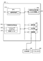
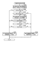
次に、本発明の実施の形態を実施例に基づき説明する。図1は、実施例における画像処理装置としての計算機200の構成を示すブロック図である。
A. Example:
A-1. Configuration of image processing device:
Next, embodiments of the present invention will be described based on examples. FIG. 1 is a block diagram illustrating a configuration of a
計算機200は、例えば、パーソナルコンピュータであり、計算機200のコントローラとしてのCPU210と、RAMなどの揮発性記憶装置220と、ハードディスクドライブなどの不揮発性記憶装置230と、マウスやキーボードなどの操作部260と、液晶ディスプレイなどの表示部270と、通信部280と、を備えている。計算機200は、通信部280を介して、印刷装置300やデジタルカメラ400などの外部装置と通信可能に接続される。
The
揮発性記憶装置220は、CPU210が処理を行う際に生成される種々の中間データを一時的に格納するバッファ領域222を提供する。不揮発性記憶装置230には、コンピュータプログラム232と、1個以上の画像ファイル234と、が格納されている。コンピュータプログラム232は、本実施例では、印刷装置300を制御するためのプリンタドライバプログラムであり、CD−ROMなどに格納される形態や、サーバからダウンロードされる形態で提供される。CPU210は、コンピュータプログラム232を実行することにより、後述する画像処理を実行する画像処理部100として機能する。
The
画像ファイル234は、画像データGDと付加情報AIとを含む(図示省略)。画像データGDは、例えば、デジタルカメラ400によって光学的に被写体を撮影することによって生成される画像データである。画像データGDは、例えば、JPEG形式で保存されている。これに代えて、TIFF形式や、GIF形式や、BMP形式や、RAWデータ形式などの保存形式が用いられても良い。付加情報AIは、例えば、撮影日時情報、撮影位置情報、絞り値や被写体距離や撮影モードなどの設定を示す設定情報などを含む。撮影日時情報は、撮影(すなわち、画像データの生成)が行われた日時を示す情報である。撮影日時情報は、例えば、年、月、時間を示す情報をそれぞれ含んでいる。撮影位置情報は、撮影(すなわち、画像データの生成)が行われた場所を示す情報である。撮影位置情報は、例えば、デジタルカメラ400に搭載されたGPS機能によって取得された緯度および経度を示す座標情報を含んでいる。
The
画像ファイル234は、画像データGDと付加情報AIとを格納可能なフォーマットに従ったファイル構造を有している。本実施例の画像ファイル234のフォーマットは、例えば、Exif(登録商標、Exchangeable image file formatの略)である。
The
A−2. 印刷処理:
計算機200のCPU210(画像処理部100)は、プリンタドライバの一機能として、画像ファイル234を用いて、いわゆる縁なし印刷によって画像を印刷する印刷処理を実行することができる。縁なし印刷は、印刷媒体の外縁に余白を残さない印刷である。本実施例の縁無し印刷では、付加画像を印刷するか否かをオプションとして選択できる。付加画像は、印刷対象の画像に関する情報を示す画像である。印刷対象の画像に関する情報は、印刷対象の画像を表す画像データGDに付加されている付加情報AIに基づく情報である。ユーザは、縁無し印刷の指示を行う際に、図示しないユーザインタフェース画面(以下、UI画面とも呼ぶ)を介して、縁無し印刷に関する設定を入力する。入力される設定は、画像ファイルの指定と、用紙のサイズ(例えば、いわゆるL版、はがき、A4など)の指定と、付加画像を印刷するか否かの指定と、を含む。
A-2. Printing process:
The CPU 210 (image processing unit 100) of the
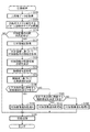
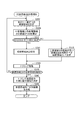
図2は、本実施例の印刷処理のフローチャートである。この印刷処理は、例えば、UI画面を介して縁なし印刷の指示がユーザから受け付けられた場合に開始される。 FIG. 2 is a flowchart of the printing process of this embodiment. This printing process is started, for example, when an instruction for borderless printing is received from the user via the UI screen.
S100では、CPU210は、元画像データを取得する。具体的には、CPU210は、不揮発性記憶装置230に格納された1個以上の画像ファイル234のうち、縁なし印刷の指示においてユーザによって指定された画像ファイルを取得する。CPU210は、取得された画像ファイルに格納された画像データをラスタライズすることによって、元画像データを取得する。元画像データは、例えば、赤(R)、緑(G)、青(B)のそれぞれの成分値(本実施例では、256階調の階調値)で色を示す色値を画素ごとに含むRGB画像データである。
In S100, the
S105では、CPU210は、ユーザによって指定された用紙のサイズと整合するように、元画像データによって表される元画像のサイズ(左右方向の画素数と上下方向の画素数)を調整する。具体的には、用紙のサイズと印刷解像度(単位は、dpi(dot per inch))との組み合わせごとに、画像のサイズが予め定められており、当該画像のサイズに元画像のサイズが調整される。この結果、左右方向の画素数に左右方向の印刷解像度を乗じて得られる画像の寸法が、用紙の左右方向の寸法より僅か(例えば、1mm〜5mm)に大きくなるように、元画像の左右方向の画素数が調整される。また、上下方向の画素数に上下方向の印刷解像度を乗じた値が、用紙の上下方向の寸法より僅か(例えば、1mm〜5mm)に大きくなるように、元画像の上下方向の画素数が調整される。なお、本明細書では、画像の上下方向を第1の方向とも呼び、画像の左右方向を第1の方向と垂直な第2の方向とも呼ぶ。
In S105, the
このサイズの調整は、例えば、縮小拡大処理およびトリミング処理の少なくとも一方を用いて実行される。具体的なサイズの調整方法は、縁無し印刷に関する公知の各種の方法、例えば、特開2008−028680に記載された方法を用いることができる。用紙のサイズと整合するように調整された元画像は、後述するS115〜S160の処理の対象とされる画像であるので対象画像とも呼ぶ。また、対象画像を表す画像データを対象画像データとも呼ぶ。 This size adjustment is executed using, for example, at least one of a reduction / enlargement process and a trimming process. As a specific method for adjusting the size, various known methods related to borderless printing, for example, a method described in JP-A-2008-028680 can be used. The original image adjusted so as to match the paper size is an image to be processed in S115 to S160 described later, and is also referred to as a target image. Further, the image data representing the target image is also called target image data.
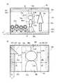
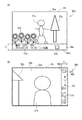
図3は、対象画像の一例を示す図である。図3(A)の対象画像20a、および、図3(B)の対象画像20bを、対象画像の例として、以下の処理を説明する。対象画像20a、20bは、矩形の画像である。対象画像20aは、人物21aと、植物22a、23aと、背景24aと、を被写体として含んでいる。対象画像20bは、人物21bと、建物22bと、背景24bと、を被写体として含んでいる。対象画像20a、20b内の矩形の一点破線で示す矩形の領域PAは、対象画像20a、20bを用紙に印刷した場合に用紙に印刷される領域を示し、領域PAより外側の領域EAは、用紙に印刷されない領域を示す。
FIG. 3 is a diagram illustrating an example of the target image. The following processing will be described using the
S110では、CPU210は、上述したユーザからの付加画像の印刷の指定があるか否かを判断する。付加画像の印刷の指定がない場合には(S110:NO)、CPU210は、S165に処理を進める。
In S110, the
付加画像の印刷の指定がある場合には(S110:YES)、CPU210は、S115にて、元画像データが格納された画像ファイルから付加情報AIを取得する。
If printing of the additional image is specified (S110: YES), the
S120では、CPU210は、付加情報AIに基づいて、付加画像用の情報、すなわち、付加画像に含めるべき情報を取得する。例えば、付加情報AIに含まれる撮影日時情報と撮影位置情報とに基づいて、対象画像の撮影時の天気を示す情報と、対象画像の撮影場所の名称を示す情報と、が取得される。これらの情報は、例えば、CPU210は、図示しないサーバに対して、インターネットを介して付加情報AIを含む情報要求を送信する。CPU210は、当該情報要求に対する応答として、サーバからこれらの情報を取得する。
In S120, the
S125では、CPU210は、付加画像が配置される配置領域の幅L1(詳細は後述)と、を決定する。本実施例では、幅L1は、用紙のサイズごとに予め決定された固定値に決定される。
In S125, the
S130では、CPU210は、対象画像データを用いて、対象画像内の人物の顔を示す顔領域FAを特定する顔領域特定処理を実行する。人物の顔は、対象画像内の主要な被写体であると考えられる。顔領域特定処理は、公知の方法を用いて実行される。例えば、顔領域特定処理としては、例えば、エッジのような低次特徴から眼や口のような高次特徴を階層的に検出し、最終的に顔の重心位置や顔の外形などを検出するコンボリューションニューラルネットワークが知られている(例えば、特開2013−120954、特開2009−237618参照)。本実施例の顔領域特定処理では、顔に外接する外接矩形が顔領域FAとして特定される。すなわち、顔に外接する外接矩形の位置およびサイズを示す情報が算出される。
In S <b> 130, the
例えば、対象画像が図3(A)の対象画像20aである場合には、人物21aの顔領域FAaが特定される。また、対象画像が図3(B)の対象画像20bである場合には、人物21bの顔領域FAbが特定される。
For example, when the target image is the
S135では、CPU210は、対象画像内に特定された顔領域FAに基づいて、対象画像の主要領域MAを決定する。主要領域MAは、顔領域FAを含む矩形の領域である。主要領域MAの上端は、顔領域FAの上端よりΔUだけ上方向に位置している。主要領域MAの下端は、顔領域FAの下端よりΔBだけ下方向に位置している。主要領域MAの右端は、顔領域FAの右端よりΔRだけ右方向に位置している。主要領域MAの左端は、顔領域FAの左端よりΔLだけ左方向に位置している。ΔU、ΔBは、例えば、顔領域FAの上下方向の長さに所定の係数Ku、Kbを乗じた値である(Ku<Kb)。ΔR、ΔLは、例えば、顔領域FAの左右方向の長さに所定の係数Krlを乗じた値である。主要領域MAは、対象画像の主要な被写体、具体的には、人物の顔を含む人物の上体部分を示す領域と呼ぶことができる。
In S135, the
図3(A)には、対象画像20aの主要領域MAaが図示され、図3(B)には、対象画像20bの主要領域MAbが図示されている。ΔU、ΔB、ΔR、ΔLは、顔領域FAが大きくなるほど大きくなる。例えば、図3(A)、(B)に示すように、ΔUa<ΔUb、ΔBa<ΔBb、ΔRa<ΔRb、ΔLa<ΔLbである。
3A shows the main area MAa of the
S140では、CPU210は、対象画像の上下方向の端(すなわち、上側の端および/または下側の端)に、削除すべき端部領域を決定できるか否かを判断する。具体的には、対象画像内の上下方向の端に、K個(Kは、1以上の整数)の端部領域を主要領域MAと重ならないように配置できるか否かが判断される。本実施例の付加画像追加処理A(後述するS150)では、上下方向の幅(すなわち、上下の端と垂直な方向の幅)がL2である2個の端部領域が削除されることによって、幅L1の配置領域が確保される(2×L2=L1)ので、K=2である。
In S140, the
図3(A)には、削除すべき端部領域の候補となる候補領域UC1、UC2、BC1、BC2が示されている。図3(A)に示すように、候補領域UC1、UC2、BC1、BC2は、上下方向の幅がL2であり、左右方向に対象画像の右端から左端まで延びる帯状の領域である。すなわち、候補領域UC1、UC2は、対象領域の上側の端に沿って、上側の端の全長に亘って延びる領域であり、候補領域BC1、BC2は、対象領域の下側の端に沿って、下側の端の全長に亘って延びる領域である。候補領域UC1、UC2は、対象画像の上側の端に候補領域UC1の上端は、対象画像(例えば、対象画像20a)の上端と同じ位置にあり、候補領域UC2は、候補領域UC1の下側に隣接している。候補領域BC1の下端は、対象画像(例えば、対象画像20a)の下端と同じ位置にあり、候補領域BC2は、候補領域BC1の上側に隣接している。
FIG. 3A shows candidate areas UC1, UC2, BC1, and BC2 that are candidates for edge areas to be deleted. As shown in FIG. 3A, the candidate regions UC1, UC2, BC1, and BC2 are band-like regions that have a vertical width of L2 and extend from the right end to the left end of the target image in the left-right direction. That is, the candidate areas UC1 and UC2 are areas extending along the upper end of the target area over the entire length of the upper end, and the candidate areas BC1 and BC2 are set along the lower end of the target area. It is an area extending over the entire length of the lower end. Candidate areas UC1 and UC2 are at the upper end of the target image, the upper end of candidate area UC1 is at the same position as the upper end of the target image (for example,
本実施例では、主要領域MAの上端から対象画像の上端までの距離DUと、主要領域MAの下端から対象画像の下端までの距離DBと、1個の端部領域の幅L2と、が以下の条件1〜3のうちの少なくとも一つを満たす場合に、対象画像の上下方向の端に削除すべき端部領域が決定できると判断される。また、距離DU、DBが以下の条件1〜3のいずれも満たさない場合に、対象画像の上下方向の端に削除すべき端部領域が決定できないと判断される。
条件1)DU≧(2×L2)
条件2)DB≧(2×L2)
条件3)DU≧L2、かつ、DB≧L2
In this embodiment, the distance DU from the upper end of the main area MA to the upper end of the target image, the distance DB from the lower end of the main area MA to the lower end of the target image, and the width L2 of one end area are as follows: In the case where at least one of the
Condition 1) DU ≧ (2 × L2)
Condition 2) DB ≧ (2 × L2)
Condition 3) DU ≧ L2 and DB ≧ L2
条件1が満たされる場合には、少なくとも、上側の2個の候補領域UC1、UC2が主要領域MAと重ならない。条件2が満たされる場合には、少なくとも、下側の2個の候補領域BC1、BC2が主要領域MAと重ならない。条件3が満たされる場合には、少なくとも、上側の1個の候補領域UC1と下側の1個の候補領域BC1とが主要領域MAと重ならない。したがって、条件1〜3のうちの少なくとも一つを満たす場合に、2個の端部領域が決定できることが解る。
When the
図3(A)の対象画像20aの例では、主要領域MAaの上端から対象画像20aの上端までの距離DUaと、主要領域MAaの下端から対象画像20aの下端までの距離DBaと、1個の端部領域の幅L2と、が条件1〜3を満たす。したがって、対象画像が対象画像20aである場合には、対象画像の上下方向の端に削除すべき端部領域を決定できると判断される。
In the example of the
図3(B)の対象画像20bの例では、主要領域MAbの上端から対象画像20bの上端までの距離DUbと、主要領域MAbの下端から対象画像20bの下端までの距離DBbと、1個の端部領域の幅L2と、が条件1〜3のいずれも満たさない。したがって、対象画像が対象画像20bである場合には、対象画像の上下方向の端に削除すべき端部領域を決定できないと判断される。
In the example of the
対象画像の上下方向の端に削除すべき端部領域を決定できない場合には(S140:NO)、CPU210は、S145にて、対象画像の左右方向の端(すなわち、右側の端および/または左側の端)に、削除すべき端部領域を決定できるか否かを判断する。具体的には、対象画像内の左右方向の端に、J個(Jは、1以上の整数)の端部領域を主要領域MAと重ならないように配置できるか否かが判断される。本実施例の付加画像追加処理B(後述するS155)では、左右方向の幅(すなわち、左右の端と垂直な方向の幅)がL2である2個の端部領域が削除されることによって、幅L1の配置領域が確保される(2×L2=L1)ので、J=2である。
If the edge region to be deleted cannot be determined at the vertical edge of the target image (S140: NO), the
図3(B)には、削除すべき端部領域の候補となる候補領域RC1、RC2、LC1、LC2が示されている。図3(B)に示すように、候補領域RC1、RC2、LC1、LC2は、左右方向の幅がL2であり、上下方向に対象画像の上端から下端まで延びる帯状の領域である。候補領域RC1、RC2は、対象領域の右側の端に沿って、右側の端の全長に亘って延びる領域であり、候補領域LC1、LC2は、対象領域の左側の端に沿って、左側の端の全長に亘って延びる領域である。候補領域RC1の右端は、対象画像(例えば、対象画像20b)の右端と同じ位置にあり、候補領域RC2は、候補領域RC1の左側に隣接している。候補領域LC1の左端は、対象画像(例えば、対象画像20b)の左端と同じ位置にあり、候補領域LC2は、候補領域LC1の右側に隣接している。
FIG. 3B shows candidate regions RC1, RC2, LC1, and LC2 that are candidates for the end region to be deleted. As shown in FIG. 3B, the candidate regions RC1, RC2, LC1, and LC2 are band-like regions that have a width in the left-right direction of L2 and extend from the upper end to the lower end of the target image in the vertical direction. Candidate areas RC1 and RC2 are areas extending along the right end of the target area over the entire length of the right end, and candidate areas LC1 and LC2 are the left end along the left end of the target area. It is the area | region extended over the full length. The right end of the candidate region RC1 is at the same position as the right end of the target image (for example, the
本実施例では、主要領域MAの右端から対象画像の右端までの距離DRと、主要領域MAの左端から対象画像の左端までの距離DLと、1個の端部領域の幅L2と、が以下の条件4〜6のうちの少なくとも一つを満たす場合に、対象画像の左右方向の端に削除すべき端部領域が決定できると判断される。また、距離DR、DLが以下の条件4〜6のいずれも満たさない場合に、対象画像の左右方向の端に削除すべき端部領域が決定できないと判断される。
条件4)DR≧(2×L2)
条件5)DL≧(2×L2)
条件6)DR≧L2、かつ、DL≧L2
In the present embodiment, the distance DR from the right end of the main area MA to the right end of the target image, the distance DL from the left end of the main area MA to the left end of the target image, and the width L2 of one end area are as follows: If at least one of the conditions 4 to 6 is satisfied, it is determined that the end region to be deleted can be determined at the left and right ends of the target image. Further, when the distances DR and DL do not satisfy any of the following conditions 4 to 6, it is determined that the end region to be deleted cannot be determined at the left and right ends of the target image.
Condition 4) DR ≧ (2 × L2)
Condition 5) DL ≧ (2 × L2)
Condition 6) DR ≧ L2 and DL ≧ L2
条件4が満たされる場合には、少なくとも、右側の2個の候補領域RC1、RC2が主要領域MAと重ならない。条件5が満たされる場合には、少なくとも、左側の2個の候補領域LC1、LC2が主要領域MAと重ならない。条件6が満たされる場合には、少なくとも、右側の1個の候補領域RC1と左側の1個の候補領域LC1とが主要領域MAと重ならない。したがって、条件4〜6のうちの少なくとも一つを満たす場合に、2個の端部領域が決定できることが解る。 When the condition 4 is satisfied, at least the two candidate areas RC1 and RC2 on the right side do not overlap with the main area MA. When the condition 5 is satisfied, at least the two left candidate areas LC1 and LC2 do not overlap the main area MA. When the condition 6 is satisfied, at least one candidate area RC1 on the right side and one candidate area LC1 on the left side do not overlap with the main area MA. Therefore, it is understood that two end regions can be determined when at least one of the conditions 4 to 6 is satisfied.
図3(B)の対象画像20bの例では、主要領域MAbの右端から対象画像20bの右端までの距離DRbと、主要領域MAbの左端から対象画像20bの左端までの距離DLbと、1個の端部領域の幅L2と、が条件4〜6を満たす。したがって、対象画像が対象画像20bである場合には、対象画像の左右方向の端に削除すべき端部領域を決定できると判断される。
In the example of the
対象画像の上下方向の端に削除すべき端部領域を決定できる場合には(S140:YES)、CPU210は、S150にて、付加画像追加処理Aを実行する。そして、対象画像の上下方向の端に削除すべき端部領域を決定できず(S140:NO)、かつ、対象画像の左右方向の端に削除すべき端部領域を決定できる場合には(S145:YES)、CPU210は、S155にて、付加画像追加処理Bを実行する。また、対象画像の上下方向の端に削除すべき端部領域を決定できず(S140:NO)、かつ、対象画像の左右方向の端に削除すべき端部領域を決定できない場合には(S145:NO)、CPU210は、S160にて、付加画像追加処理Cを実行する。付加画像追加処理A〜Cについては、後述するが、いずれの処理が実行される場合であっても、これらの処理A〜Cによって、対象画像の少なくとも一部の画像と、付加画像と、を含む処理済み画像を表す処理済み画像データが生成される。付加画像追加処理A〜Cが終了すると、CPU210は、S165に処理を進める。
If the end region to be deleted can be determined at the vertical end of the target image (S140: YES), the
S165では、CPU210は、印刷処理を実行する。付加画像の印刷の指定がある場合には(S110:YES)、付加画像追加処理A〜Cによって生成される処理済み画像データが、印刷処理の対象とされ、付加画像の印刷の指定がない場合には(S110:NO)、対象画像データが、印刷処理の対象とされる。具体的には、CPU210は、印刷処理の対象の画像データに対して、色変換処理やハーフトーン処理を実行することによって、印刷データを生成する。CPU210は、生成された印刷データを印刷装置300に供給することによって、印刷装置300に、対象画像、または、処理済み画像を印刷する縁なし印刷を実行させる。
In S165, the
A−3.付加画像追加処理A:
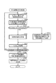
図4は、図2のS150の付加画像追加処理Aのフローチャートである。ここでは、対象画像が図3(A)の対象画像20aである場合を例に、説明する。S200では、CPU210は、対象画像20a内に、上下方向に1個ずつの候補領域を設定する。具体的には、初回のS200では、対象画像20aの上端から幅L2分の候補領域UC1が第1候補領域として設定される。そして、対象画像20aの下端から幅L2分の候補領域BC1が第2候補領域として設定される。
A-3. Additional image addition processing A:
FIG. 4 is a flowchart of the additional image addition process A in S150 of FIG. Here, a case where the target image is the
S205では、CPU210は、主要領域MAaと第1候補領域との上下方向の距離D1と、主要領域MAaと第2候補領域との上下方向の距離D2と、を算出する。例えば、図3(A)には、候補領域UC1が第1候補領域であり、候補領域BC1が第2候補領域である場合に、算出される距離D1、D2が図示されている。
In S205, the
S210では、CPU210は、距離D1が閾値Dth1以上であり、かつ、距離D2がDth2以上であるか否かを判断する。例えば、閾値Dth1は、主要領域MAaの上下方向の幅の10%〜50%程度の値に決定される。
In S210, the
距離D1が閾値Dth1未満である場合、または、距離D2が閾値Dth2未満である場合には(S210:NO)、すなわち、主要領域MAaと1個の候補領域との間の距離が比較的短い場合には、CPU210は、S215に処理を進める。
When the distance D1 is less than the threshold value Dth1, or when the distance D2 is less than the threshold value Dth2 (S210: NO), that is, when the distance between the main area MAa and one candidate area is relatively short. In step S215, the
S215では、CPU210は、第1候補領域と第2候補領域とのうち、主要領域MAaとの間の距離がより長い候補領域を、削除すべき端部領域として決定する。換言すれば、対象画像の互いに対向する異なる端に沿った複数個の候補領域(すなわち、第1候補領域と第2候補領域)のうち、主要領域MAaに含まれる特定の被写体(例えば、顔を含む人物の上体部分)からの距離が離れた領域が優先的に、削除すべき端部領域として決定される。主要領域MAaに過度に近い領域が、後述するトリミング処理(図4のS230)において端部領域として対象画像から削除されると、処理済み画像において主要領域MAaが中心から離れて画像の端に近づくことによって、処理済み画像が不適切な画像になる可能性がある。本実施例では、このような不都合の発生を防止することができる。すなわち、処理済み画像が不適切な画像となることを抑制できる。
In S215, the
距離D1が閾値Dth1以上であり、かつ、距離D2がDth2以上である場合(S210:YES)、すなわち、主要領域MAaと各候補領域との距離が比較的長い場合には、CPU210は、S220にて、端部領域決定処理を実行する。端部領域決定処理は、第1候補領域内の画像の複雑さと、第2候補領域内の画像の複雑さと、の比較に基づいて、第1候補領域と第2候補領域のうちの一方の領域を、削除すべき端部領域として決定する処理である。
When the distance D1 is equal to or greater than the threshold value Dth1 and the distance D2 is equal to or greater than Dth2 (S210: YES), that is, when the distance between the main area MAa and each candidate area is relatively long, the
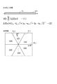
図5は、端部領域決定処理のフローチャートである。図6は、端部領域決定処理の説明図である。S500では、CPU210は、第1候補領域と第2候補領域のばらつき値VE1、VE2を算出する。候補領域のばらつき値VEは、候補領域内の画像に含まれる複数個の画素の値のばらつきを示す指標値である。図6(A)には、算出対象の候補領域が、図3(A)の候補領域UC1である場合を例に、ばらつき値VEの算出法が図示されている。候補領域UC1の短手方向の中心を通り、候補領域UC1の長手方向の一端から他端まで延びるラインCL上に並ぶ一列分の画素の個数をNとする(Nは、2以上の整数)。当該N個の一列分の画素のそれぞれに、一端から他端に向かって並ぶ順序を示す番号n(nは、1≦n≦Nの整数)を付す。この場合には、ばらつき値VEは、図6(A)の式(1)を用いて、表される。ΔE(n)は、n番目の画素と(n+1)番目の画素との色差、すなわち、隣接する2個の画素の間で色が異なる度合を表す値である。n番目の画素の色値(RGB値)をCIELAB色空間の色値(L*値、a*値、b*値)に変換した値を(Ln、an、bn)とする。ΔE(n)は、図6(A)の式(2)を用いて表される。すなわち、ΔE(n)は、n番目の画素の色値(Ln、an、bn)と、(n+1)番目の画素の色値(Ln+1、an+1、bn+1)とのCIELAB色空間におけるユークリッド距離である。以上の説明から解るように、ばらつき値VEは、N個の画素の(N−1)組の隣接画素間の色差ΔE(n)の合計値である。ばらつき値VEは、候補領域内の画像の複雑さを示す値と言うことができる。ばらつき値VEが大きいほど、候補領域内の画像の複雑さが高いことを示している。
FIG. 5 is a flowchart of the edge area determination process. FIG. 6 is an explanatory diagram of the edge region determination process. In S500, the
S505では、CPU210は、第2候補領域のばらつき値VE2から第1候補領域のばらつき値VE1を減じた差分(VE2−VE1)が、所定の閾値TH1以上である否かを判断する。換言すれば、2個の領域のばらつき値VE1、VE2が、第1候補領域内の画像の複雑さが第2候補領域内の画像より十分に低いことを示すか否かが判断される。差分(VE2−VE1)が、所定の閾値TH1以上である場合(S505:YES)、CPU210は、S535にて、第1候補領域を削除すべき端部領域として決定する。
In S505, the
差分(VE2−VE1)が、所定の閾値TH1より小さい場合には(S505:NO)、CPU210は、S510にて、第1候補領域のばらつき値VE1から第2候補領域のばらつき値VE2を減じた差分(VE1−VE2)が、所定の閾値TH1以上である否かを判断する。換言すれば、2個の領域のばらつき値VE1、VE2が、第2候補領域内の画像の複雑さが第1候補領域内の画像より十分に低いことを示すか否かが判断される。差分(VE1−VE2)が、所定の閾値TH1以上である場合(S510:YES)、CPU210は、S540にて、第2候補領域を削除すべき端部領域として決定する。
When the difference (VE2-VE1) is smaller than the predetermined threshold TH1 (S505: NO), the
差分(VE1−VE2)が、所定の閾値TH1より小さい場合には(S510:NO)、CPU210は、S515にて、第1候補領域の色数CV1と、第2候補領域の色数CV2と、を算出する。候補領域の色数CVは、画素の色値(RGB値)によって表される色を、色相に応じて複数種類の色(本実施例では、6種類の色)に分類した場合に、候補領域内の画像に含まれる色の種類の数を表す値である。図6(B)には、CIELAB色空間における、a*値の軸とb*値の軸とを含むab平面が示されている。この図に示すように、CIELAB色空間には、無彩色軸(a*値=b*=0の軸)を含み、ab平面に垂直な3つの平面PL1〜PL3によって等分割された6個の部分空間CA1〜CA6が設定される。CPU210は、候補領域内の全ての画素の色値(RGB値)を、CIELAB色空間の色値(L*値、a*値、b*値)に変換する。CPU210は、各画素の色値に応じて、各画素を6つの部分空間CA1〜CA6のいずれかに分類する。そして、CPU210は、6個の部分空間CA1〜CA6のうち、基準数以上(例えば、1個以上)の画素が分類された部分空間の個数を色数CVとして算出する。したがって、候補領域の色数CVは、1〜6のうちのいずれかの値を取る。色数CVは、候補領域内の画像の複雑さを示す値と言うことができる。色数CVが大きいほど、候補領域内の画像の複雑さが高いことを示している。なお、CIELAB色空間の分割数は、6に限らず、12、18などの他の個数であっても良い。
When the difference (VE1-VE2) is smaller than the predetermined threshold value TH1 (S510: NO), the
S520では、CPU210は、第1候補領域の色数CV1が第2候補領域の色数CV2がより小さいか否かを判断する。第1候補領域の色数CV1が第2候補領域の色数CV2より小さい場合には(S520:YES)、CPU210は、S535にて、第1候補領域を削除すべき端部領域として決定する。第1候補領域の色数CV1が第2候補領域の色数CV2以上である場合には(S520:NO)、CPU210は、S525にて、第2候補領域の色数CV2が第1候補領域の色数CV1より小さいか否かを判断する。第2候補領域の色数CV2が第1候補領域の色数CV1より小さい場合には(S525:YES)、CPU210は、S540にて、第2候補領域を削除すべき端部領域として決定する。
In S520, the
第2候補領域の色数CV2と第1候補領域の色数CV1とが等しい場合には(S525:YES)、CPU210は、S530にて、第1候補領域のばらつき値VE1が第2候補領域のばらつき値VE2より小さいか否かを判断する。第1候補領域のばらつき値VE1が第2候補領域のばらつき値VE2より小さい場合には(S530:YES)、CPU210は、S535にて、第1候補領域を削除すべき端部領域として決定する。第1候補領域のばらつき値VE1が第2候補領域のばらつき値VE2以上である場合には(S530:NO)、CPU210は、S540にて、第2候補領域を削除すべき端部領域として決定する。
When the number of colors CV2 of the second candidate area is equal to the number of colors CV1 of the first candidate area (S525: YES), the
以上の説明から解るように、この端部領域決定処理によれば、第1候補領域内の画像の複雑さを示す第1の値として、ばらつき値VE1や色数CV1が、第1候補領域内の複数個の画素の値を用いて算出される(S500、S515)。また、第2候補領域内の画像の複雑さを示す第2の値として、ばらつき値VE2や色数CV2が、第2候補領域内の複数個の画素の値を用いて算出される。そして、これらの値(ばらつき値VE1、VE2、色数CV1、CV2)に基づいて、第1候補領域と第2候補領域とのうち、画像の複雑さが低い領域が優先的に端部領域として決定される(S505、S510、S520〜S530)。画像の複雑さが高い領域には、対象画像の特徴的な部分を含む可能性がある。しがたって、この端部領域決定処理によれば、複雑さが低い領域が優先的に端部領域に決定される。この結果、後述するトリミング処理(図4のS230)によって、対象画像の特徴的な部分が処理済み画像から除かれることを抑制することができる。 As can be understood from the above description, according to this edge region determination process, the variation value VE1 and the color number CV1 are used as the first value indicating the complexity of the image in the first candidate region. Is calculated using the values of the plurality of pixels (S500, S515). Further, as the second value indicating the complexity of the image in the second candidate area, the variation value VE2 and the number of colors CV2 are calculated using the values of a plurality of pixels in the second candidate area. Then, based on these values (variation values VE1, VE2, color numbers CV1, CV2), the first candidate region and the second candidate region are preferentially selected as the end region as a region having a low image complexity. It is determined (S505, S510, S520 to S530). There is a possibility that a region having high image complexity includes a characteristic portion of the target image. Therefore, according to the end region determination process, a region with low complexity is preferentially determined as the end region. As a result, it is possible to prevent a characteristic portion of the target image from being removed from the processed image by a trimming process (S230 in FIG. 4) described later.
また、ばらつき値VEが比較的大きな候補領域ほど、画像の複雑さが高いと判断されるので、例えば、エッジ量が多い候補領域は、端部領域として決定されにくい。また、ばらつき値VEが比較的小さい候補領域であっても、色数CVが多い領域は、画像の複雑さが高いと判断されるので、端部領域として決定されにくい。例えば、エッジ量が比較的少なく、かつ、比較的広い色相範囲の色が含まれる領域(例えば、グラデーションを含む領域)は、端部領域として決定されにくい。この結果、CPU210は、ばらつき値VEと、色数CVと、に基づいて、候補領域内の画像の複雑さを適切に評価して、適切な候補領域を削除すべき端部領域として決定することができる。
Further, since it is determined that the candidate area having a relatively large variation value VE has a higher image complexity, for example, a candidate area having a large amount of edge is not easily determined as an end area. Even if the candidate area has a relatively small variation value VE, an area having a large number of colors CV is determined to have a high image complexity, and thus is not easily determined as an end area. For example, an area where the edge amount is relatively small and a color in a relatively wide hue range (for example, an area including gradation) is difficult to be determined as an end area. As a result, the
図4に戻って説明を続ける。S215またはS220において、1個の候補領域が端部領域として決定されると、S230にて、CPU210は、トリミング処理を実行する。トリミング処理は、現時点での対象画像20aから直前のS215またはS220において決定された端部領域を削除して、対象画像20aから端部領域を除いた領域内の画像を表す画像データを生成する処理である。例えば、S220にて候補領域UC1(図3(A))が1個目の端部領域として決定されたとする。この場合には、S230のトリミング処理では、候補領域UC1が削除されて、対象画像20aの上下方向の長さは、候補領域UC1の幅L2分だけ短くなる。
Returning to FIG. 4, the description will be continued. When one candidate area is determined as an edge area in S215 or S220,
S235では、CPU210は、付加画像の配置領域分の端部領域をトリミング処理によって対象領域から削除したか否かを判断する。本実施例では、図3(A)に示すように、付加画像の配置領域の幅L1は、1個の端部領域の幅L2の2倍であるので、2個の端部領域が削除されたか否かが判断される。例えば、最初のS230にて、候補領域UC1(図3(A))が1個目の端部領域として対象画像20aから削除された場合には、直後のS235にて、CPU210は、配置領域分の端部領域を削除していないと判断する。配置領域分の端部領域が削除されていない場合には(S235:NO)、CPU210は、S200に戻って、上下に1個ずつの候補領域、すなわち、第1候補領域と第2候補領域とを設定する。
In S235, the
付加画像追加処理Aの第1候補領域は、トリミング処理前の対象画像20aの上側の端に沿って配置可能な1個以上の候補領域(例えば、図3(A)の候補領域UC1、UC2)であり、かつ、削除すべき端部領域として決定されていない1個以上の候補領域のうち、最も上側に位置する領域である。したがって、例えば、最初のS230にて候補領域UC1が1個目の端部領域として対象画像20aから削除されている場合には、2回目のS200では、候補領域UC2が第1候補領域として決定される。
The first candidate area of the additional image addition process A is one or more candidate areas that can be arranged along the upper edge of the
付加画像追加処理Aの第2候補領域は、トリミング処理前の対象画像の下側の端に沿って配置可能な1個以上の候補領域(例えば、図3(A)の候補領域BC1、BC2)であり、かつ、削除すべき端部領域として決定されていない1個以上の候補領域のうち、最も下側に位置する領域である。したがって、例えば、最初のS230にて候補領域UC1が1個目の端部領域として対象画像20aから削除されている場合には、2回目のS200では、1回目と同じく、候補領域BC1が第2候補領域として決定される。したがって、2回目のS210〜S220の処理では、第1候補領域としての候補領域UC2と、第2候補領域としての候補領域BC1と、のうちの1個の候補領域が、削除すべき2個目の端部領域として決定される。ここでは、2回目のS210〜S220の処理では、下側の候補領域BC1が削除すべき2個目の端部領域として決定され、2回目のS230では下側の候補領域BC1が対象画像20aから削除されるものとする。
The second candidate area of the additional image addition process A is one or more candidate areas that can be arranged along the lower edge of the target image before the trimming process (for example, candidate areas BC1 and BC2 in FIG. 3A). And is the lowermost region among one or more candidate regions that are not determined as end regions to be deleted. Therefore, for example, when the candidate area UC1 is deleted from the
2個目の端部領域が削除された後のS235では、CPU210は、配置領域分の端部領域を削除したと判断する。配置領域分の端部領域が削除された場合には(S235:YES)、CPU210は、S240に処理を進める。配置領域分の端部領域が削除された後の対象画像を、トリミング済み画像とも呼ぶ。
In S235 after the second end area is deleted, the
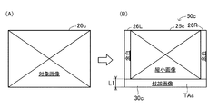
図7は、処理済み画像の一例を示す図である。図7(A)には、図3(A)の対象画像20aに対して付加画像追加処理Aを実行した場合に生成される処理済み画像50aが示されている。処理済み画像50aは、トリミング済み画像25aと、付加画像30aと、を含んでいる。また、処理済み画像50aは、削除された端部領域内の画像を含んでいない。トリミング済み画像25aは、対象画像20aから削除すべき2個の端部領域UC1、BC2を除いた領域(印刷対象領域とも呼ぶ)内の画像である、と言うことができる。
FIG. 7 is a diagram illustrating an example of a processed image. FIG. 7A shows a processed
図7(A)の処理済み画像50aの付加画像30aは、S240とS245の処理によって、トリミング済み画像25a(すなわち、対象画像20aの印刷対象領域内の画像)の下側にトリミング済み画像25aと重ならずに配置される。
The
先ず、S240では、CPU210は、付加画像30aを配置するための配置領域TAaを設定する。図7(A)に示すように、配置領域TAaは、上下方向の幅がL1であり、左右方向の幅がトリミング済み画像25aと同じである矩形の領域である。配置領域TAaは、処理済み画像50aの下側に、処理済み画像50aと重ならずに配置される。
First, in S240, the
S245では、CPU210は、対象画像20aの配置領域TAa内に付加画像30aを形成して、処理済み画像50aを完成させる(図7(A))。付加画像30aは、テキスト31aとQRコード32aとを含む(QRコードは登録商標)。テキスト31aは、付加情報AIに基づく情報、具体的には、撮影の日時と、撮影の場所と、撮影時の天気と、を示している。QRコード32aは、付加情報AIに基づく情報にアクセスするためのURL(Uniform Resource Locatorの略)、本実施例では、撮影の場所の地図を示すWEBページにアクセスするためのURLを示している。
In S245, the
図7(A)に示すように、付加画像30a(配置領域TAa)の上下方向の幅は、L1である。そして、トリミング済み画像25aの上下方向の幅は、対象画像20aより2個の端部領域の上下方向の幅(2×L2=L1)だけ短い。したがって、トリミング済み画像25aと付加画像30aとを含む処理済み画像50aの上下方向の幅は、対象画像20aの上下方向の幅と等しい。すなわち、対象画像20aのサイズと、処理済み画像50aのサイズとは、互いに等しい。さらに、トリミング済み画像25aは、対象画像20aから上側の端部領域UC1と下側の端部領域BC1とを削除した画像である。そして、処理済み画像50aにおいて、付加画像30aは、トリミング済み画像25aの下側に配置されている。このために、処理済み画像50aにおける被写体21a〜23aの位置は、対象画像20aにおける被写体21a〜23aの位置より、L2だけ上側にシフトしている。すなわち、処理済み画像50aにおける被写体21a〜23aの位置と、対象画像20aにおける被写体21a〜23aの位置とは、ずれている(一致していない)。
As shown in FIG. 7A, the vertical width of the
A−4.付加画像追加処理B:
図8は、図2のS155の付加画像追加処理Bのフローチャートである。ここでは、対象画像が図3(B)の対象画像20bである場合を例に、説明する。S300では、CPU210は、対象画像20b内に、左右方向に1個ずつの候補領域を設定する。具体的には、初回のS300では、対象画像20bの右端から幅L2分の候補領域RC1(図3(B))が第1候補領域として設定される。そして、対象画像20bの左端から幅L2分の候補領域BC1(図3(B))が第2候補領域として設定される。
A-4. Additional image addition processing B:
FIG. 8 is a flowchart of the additional image addition process B in S155 of FIG. Here, a case where the target image is the
S305では、CPU210は、主要領域MAbと第1候補領域との左右方向の距離D3と、主要領域MAbと第2候補領域との左右方向の距離D4と、を算出する。例えば、図3(B)には、候補領域RC1が第1候補領域であり、候補領域LC1が第2候補領域である場合に、算出される距離D3、D4が図示されている。
In S305, the
S310では、CPU210は、距離D3が閾値Dth3以上であり、かつ、距離D4がDth4以上であるか否かを判断する。例えば、閾値Dth3は、主要領域MAbの左右方向の幅の10%〜50%程度の値に決定される。
In S310, the
距離D3が閾値Dth3未満である場合、または、距離D4が閾値Dth4未満である場合には(S310:NO)、すなわち、主要領域MAbと1個の候補領域との間の距離が比較的短い場合には、CPU210は、S315に処理を進める。
When the distance D3 is less than the threshold value Dth3, or when the distance D4 is less than the threshold value Dth4 (S310: NO), that is, when the distance between the main region MAb and one candidate region is relatively short In step S315, the
S315では、CPU210は、第1候補領域と第2候補領域とのうち、主要領域MAbとの間の距離がより長い候補領域を、削除すべき端部領域として決定する。
In S315, the
距離D3が閾値Dth3以上であり、かつ、距離D4がDth4以上である場合(S310:YES)、すなわち、主要領域MAbと各候補領域との距離が比較的長い場合には、CPU210は、S320にて、図5の端部領域決定処理を実行する。端部領域決定処理によって、付加画像追加処理Aと同様に、第1候補領域と第2候補領域のうちの一方の領域が、削除すべき端部領域として決定される。
If the distance D3 is greater than or equal to the threshold Dth3 and the distance D4 is greater than or equal to Dth4 (S310: YES), that is, if the distance between the main area MAb and each candidate area is relatively long, the
S315またはS320において、1個の候補領域が端部領域として決定されると、S330にて、CPU210は、トリミング処理を実行する。トリミング処理は、現時点での対象画像20bから、直前のS315またはS320において決定された端部領域を削除して、端部領域を除いた部分の画像を表す画像データを生成する処理である。例えば、S320にて候補領域RC1(図3(B))が1個目の端部領域として決定されたとする。この場合には、S330のトリミング処理では、候補領域RC1が削除されて、対象画像20bの左右方向の長さは、候補領域RC1の幅L2分だけ短くなる。
When one candidate area is determined as an edge area in S315 or S320, the
S335では、CPU210は、付加画像の配置領域分の端部領域をトリミング処理によって対象領域から削除したか否かを判断する。本実施例では、図3(B)に示すように、付加画像の配置領域の幅L1は、1個の端部領域の幅L2の2倍であるので、2個の端部領域が削除されたか否かが判断される。配置領域分の端部領域が削除されていない場合には(S335:NO)、CPU210は、S300に戻って、左右に1個ずつの候補領域、すなわち、第1候補領域と第2候補領域とを設定する。
In S335, the
付加画像追加処理Bの第1候補領域は、トリミング処理前の対象画像20bの右側の端に沿って配置可能な1個以上の候補領域(例えば、図3(B)の候補領域RC1、RC2)であり、かつ、削除すべき端部領域として決定されていない1個以上の候補領域のうち、最も右側に位置する領域である。
The first candidate area of the additional image addition process B is one or more candidate areas that can be arranged along the right edge of the
付加画像追加処理Bの第2候補領域は、トリミング処理前の対象画像の左側の端に沿って配置可能な1個以上の候補領域(例えば、図3(B)の候補領域LC1、LC2)であり、かつ、削除すべき端部領域として決定されていない1個以上の候補領域のうち、最も左側に位置する領域である。 The second candidate area of the additional image addition process B is one or more candidate areas (for example, candidate areas LC1 and LC2 in FIG. 3B) that can be arranged along the left edge of the target image before the trimming process. This is a leftmost region among one or more candidate regions that are present and are not determined as end regions to be deleted.
ここでは、最初のS310〜S320の処理では、右側の候補領域RC1が削除すべき1個目の端部領域として決定され、2回目のS310〜S320の処理では、右側の候補領域RC2が削除すべき2個目の端部領域として決定されるものとする。したがって、2回のS330の処理によって、右側の2個の候補領域RC1、RC2が対象画像20bから端部領域として削除されて、トリミング済み画像25b(図7(B))を表す画像データが生成される。
Here, in the first processing of S310 to S320, the right candidate region RC1 is determined as the first end region to be deleted, and in the second processing of S310 to S320, the right candidate region RC2 is deleted. It is assumed that it is determined as the second end region. Accordingly, the two candidate regions RC1 and RC2 on the right side are deleted as end regions from the
2個目の端部領域が削除された後のS335では、CPU210は、配置領域分の端部領域を削除したと判断する。配置領域分の端部領域が削除された場合には(S335:YES)、CPU210は、S340にて、トリミング済み画像25bの右側に付加画像30bを配置するための配置領域TAbを設定する。図7(B)に示すように、配置領域TAbは、左右方向の幅がL1であり、上下方向の幅がトリミング済み画像25bと同じである矩形の領域である。
In S335 after the second end area is deleted, the
S345では、CPU210は、対象画像20bの配置領域TAb内に付加画像30bを形成して、処理済み画像50bを完成させる(図7(B))。付加画像30bは、付加画像30a(図7(A))と同様に、テキスト31bとQRコード32bとを含む。
In S345, the
図7(A)の処理済み画像50aと同様に、処理済み画像50bのサイズは、対象画像20bのサイズと等しい。さらに、トリミング済み画像25bは、対象画像20bから右側の2個の端部領域RC1、RC2を削除した画像である。そして、処理済み画像50bにおいて、付加画像30bは、トリミング済み画像25bの右側に配置されている。このために、処理済み画像50bにおける被写体21b、22bの位置と、対象画像20bにおける被写体21b、22bの位置とは、一致している(ずれていない)。
Similar to the processed
A−5.付加画像追加処理C:
図9は、図2のS160の付加画像追加処理Cのフローチャートである。図10は、通知画面WPの一例を示す図である。図11は、付加画像追加処理Cの説明図である。図11に示す対象画像20cは、上下左右の端の近傍にまで、顔領域FAを含む主要領域MAが位置しているために、上下方向の端に沿った端部領域と、左右方向の端に沿った端部領域と、のいずれも削除すべき端部領域として決定できない画像であるとする。以下では、対象画像が図11の対象画像20cであるとして、説明する。
A-5. Additional image addition processing C:
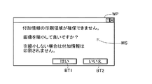
FIG. 9 is a flowchart of the additional image addition process C in S160 of FIG. FIG. 10 is a diagram illustrating an example of the notification screen WP. FIG. 11 is an explanatory diagram of the additional image addition process C. Since the main area MA including the face area FA is located in the vicinity of the top, bottom, left, and right edges of the
図9のS400では、CPU210は、表示部270に通知画面WP(図10)を表示する。通知画面WPは、メッセージMSと、2個のボタンBT1、BT2と、を含んでいる。メッセージMSは、対象画像を縮小することなく付加画像の印刷領域を確保することができないことを示すとともに、対象画像20cを縮小する指示を求めるメッセージである。ボタンBT1は、ユーザが、対象画像20cを縮小する指示を入力するためのボタンである。ボタンBT2は、ユーザが、対象画像20cを縮小しない指示を入力するためのボタンである。CPU210は、通知画面WPを介して、対象画像を縮小するか否かを示す指示を受け取る。
In S400 of FIG. 9, the
S405では、CPU210は、ユーザの指示が、対象画像20cを縮小する縮小指示であるか否かを判断する。CPU210は、ユーザの指示が縮小指示である場合には(S405:YES)、S410にて、対象画像データに対して縮小処理を実行する。縮小処理によって、対象画像20cは、上下方向の長さがL1だけ短くなるように、かつ、上下方向の長さと左右方向の長さの比率(アスペクト比)を維持するように、縮小される。例えば、図11(A)の対象画像20cが縮小されて、図11(B)の縮小画像25cが生成される。
In S405, the
S415では、CPU210は、縮小画像25cを含む処理済み画像のサイズが、対象画像20cのサイズと同じになるように、縮小画像25cに対して配置領域TAcと余白26L、26Rとを設定する(図11(B))。余白26L、26Rの左右方向の幅は、互いに等しい。そして、縮小画像25cの下側に、縮小画像25cと重ならないように、配置領域TAcが配置される。配置領域TAcは、上下方向の幅がL1であり、左右方向の幅が対象画像20cと同じである矩形の領域である。
In S415, the
S420では、CPU210は、対象画像20cの下側の配置領域TAa内に付加画像30c(図11(B))を形成して、処理済み画像50cを完成させる(図11(B))。付加画像30cは、図7の付加画像30aと同様の画像である。
In S420, the
ユーザの指示が縮小指示でない場合には(S405:NO)、CPU210は、S410〜S420をスキップして、付加画像追加処理Cを終了する。この場合には、付加画像の追加は行われないので、図2のS165の印刷処理にて、付加画像を含まない対象画像が印刷される。
If the user instruction is not a reduction instruction (S405: NO), the
以上説明した上記実施例によれば、対象画像(例えば、図3の対象画像20a、20b)内の被写体の特徴に基づいて、対象画像の端に沿った削除すべき端部領域(例えば、端部領域UC1、RC1)が決定される。すなわち、顔領域FAを含む主要領域MAの位置に基づいて、削除すべき端部領域と、対象画像から削除すべき端部領域を除いた印刷対象領域と、が決定される。そして、削除すべき端部領域内の画像を含まず、トリミング済み画像(すなわち、印刷対象領域内の画像)と付加画像とを含む処理済み画像(例えば、図7の処理済み画像50a、50b)を表す処理済み画像データが生成される。この結果、付加画像を含む画像を印刷する場合に、印刷される画像の見栄えが損なわれる可能性を低減することができる。具体的には、特に、本実施例のように、縁なし印刷が行われる場合のように、用紙上の印刷可能領域の全体に対象画像の背景を含む被写体が配置されている場合には、対象画像の外側に付加画像を配置することはできない。このために、例えば、付加画像内の情報(テキスト31a、31bや、QRコード32a、32b)を対象画像に重ねて配置すると、対象画像内の被写体が見づらくなる可能性や、付加画像内の情報が見づらくなる場合があった。また、対象画像を縮小して付加画像の配置領域を確保すると、対象画像内の被写体が過度に小さく印刷される可能性があった。さらに、被写体の特徴に基づかずに、不用意に端部領域を削除して付加画像の配置領域を確保すると、対象画像内の被写体の特徴的な部分が処理済み画像に含まれなくなる可能性があった。本実施例では、このような不都合を抑制して、印刷される画像の見栄えが損なわれる可能性を低減することができる。
According to the embodiment described above, based on the characteristics of the subject in the target image (for example, the
さらに、本実施例では、顔領域FAを含む主要領域MAを除いた領域内に、削除すべき端部領域が決定される(図2のS140、S145など)。したがって、人物の顔の全体が処理済み画像に含まれるように、適切に処理済み画像データを生成できる。 Further, in the present embodiment, the end area to be deleted is determined in the area excluding the main area MA including the face area FA (S140, S145, etc. in FIG. 2). Therefore, appropriately processed image data can be generated so that the entire face of a person is included in the processed image.
より具体的には、上側の端に沿った領域と下側の端に沿った領域とのそれぞれについて、削除すべき端部領域として決定するか否かが判断され(図2のS140)、上側の端に沿った領域と下側の端に沿った領域との両方を端部領域として決定しない場合に(図2のS140:NO)、対象画像の右側の端に沿った領域と左側の端に沿った領域とについて、端部領域として決定するか否かを判断する(図2のS145)。この結果、対象画像の上下方向の端に沿った領域が、左右方向の端に沿った領域より優先的に削除すべき端部領域として決定される。この結果、対象画像内の被写体の特徴に基づいてより適切な方向の端部領域を決定することができる。例えば、特に、付加情報が横書きのテキストを含む場合には、対象画像の上下方向の端に沿った領域を端部領域として削除すると、横長の付加画像を配置できるので、より見やすい。したがって、対象画像の上下方向の端に沿った領域を左右方向の端に沿った領域より優先的に端部領域として決定することが好ましい。 More specifically, it is determined whether or not each of the region along the upper end and the region along the lower end is determined as an end region to be deleted (S140 in FIG. 2). When both the area along the edge of the image and the area along the lower edge are not determined as the edge area (S140: NO in FIG. 2), the area along the right edge of the target image and the left edge It is determined whether or not the region along the line is determined as the end region (S145 in FIG. 2). As a result, the area along the vertical edge of the target image is determined as the edge area to be preferentially deleted over the area along the horizontal edge. As a result, an end region in a more appropriate direction can be determined based on the characteristics of the subject in the target image. For example, in particular, when the additional information includes horizontally written text, if a region along the vertical edge of the target image is deleted as an end region, a horizontally long additional image can be arranged, which is easier to see. Therefore, it is preferable to preferentially determine the area along the vertical edge of the target image as the edge area over the area along the horizontal edge.
さらに、上側の端に沿った領域と下側の端に沿った領域との両方を端部領域として決定せず(図2のS140:NO)、かつ、右側の端に沿った領域と左側の端に沿った領域との両方を端部領域として決定しない場合には(図2のS145:NO)、対象画像が縮小された縮小画像(例えば、図11の縮小画像25c)を表す縮小画像データが生成される(図2のS160、図9)。したがって、上下左右の端に沿った領域がいずれも端部領域として決定されない場合には、縮小画像と付加画像とを含む適切な処理済み画像を生成することができる。
Furthermore, both the region along the upper end and the region along the lower end are not determined as end regions (S140: NO in FIG. 2), and the region along the right end and the left side are not determined. When both the region along the edge and the region along the edge are not determined as the edge region (S145: NO in FIG. 2), the reduced image data representing the reduced image (for example, the reduced
さらに、上側の端に沿った領域と下側の端に沿った領域との両方を端部領域として決定せず(図2のS140:NO)、かつ、右側の端に沿った領域と左側の端に沿った領域との両方を端部領域として決定しない場合には(図2のS145:NO)、端部領域を決定できないこと、すなわち、対象画像を縮小することなく付加画像の印刷領域を確保できないことがユーザに通知される(図9のS400、図10)。この結果、ユーザは、対象画像から除かれる端部領域を自動で決定できないこと、換言すれば、付加画像を配置するための対象画像の自動的なトリミングができないことを認識することができる。 Furthermore, both the region along the upper end and the region along the lower end are not determined as end regions (S140: NO in FIG. 2), and the region along the right end and the left side are not determined. If both the area along the edge and the area along the edge are not determined as the edge area (S145: NO in FIG. 2), the edge area cannot be determined, that is, the print area of the additional image is not reduced without reducing the target image. The user is notified that it cannot be secured (S400 in FIG. 9, FIG. 10). As a result, the user can recognize that the end area excluded from the target image cannot be automatically determined, in other words, that the target image for arranging the additional image cannot be automatically trimmed.
さらに、上記実施例の付加画像追加処理A(図4)、および、付加画像追加処理B(図8)では、幅L1の付加画像を配置するために、幅L1より小さな幅L2の複数個の候補領域のそれぞれについて、端部領域として決定するか否かが判断される(図4のS220、図8のS320)。そして、K個の候補領域が前記端部領域として決定される。このように、幅L1より小さな幅L2の複数個の候補領域に分けて、削除すべき端部領域を決定するので、例えば、複雑さが比較的高い特徴的な領域が端部領域として決定される可能性をより低減することができる。なお、付加画像の幅L1と、1個の端部領域(候補領域)の幅L2のK倍は、ほぼ等しいことが好ましい(L1≒K×L2)。こうすれば、必要以上に、対象画像が小さくなることを抑制することができる。 Furthermore, in the additional image addition process A (FIG. 4) and the additional image addition process B (FIG. 8) of the above embodiment, in order to arrange the additional image having the width L1, a plurality of width L2 smaller than the width L1 are arranged. Whether each of the candidate areas is determined as an end area is determined (S220 in FIG. 4 and S320 in FIG. 8). Then, K candidate areas are determined as the end areas. As described above, the edge region to be deleted is determined by dividing the plurality of candidate regions with the width L2 smaller than the width L1, and for example, a characteristic region having a relatively high complexity is determined as the edge region. The possibility of being reduced can be further reduced. It is preferable that the additional image width L1 and the width L2 of one edge region (candidate region) be approximately equal to K (L1≈K × L2). In this way, it is possible to suppress the target image from becoming smaller than necessary.
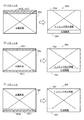
なお、上記実施例の付加画像追加処理A(図4)で、処理済み画像が生成されるパターンには、以下の3つがある。図12は、処理済み画像が生成されるパターンの一例を示す図である。 Note that there are the following three patterns in which processed images are generated in the additional image addition processing A (FIG. 4) of the above embodiment. FIG. 12 is a diagram illustrating an example of a pattern in which a processed image is generated.
パターンA(図12(A))
対象画像20dの上側に位置する2個の端部領域UC1、UC2が削除されて、トリミング済み画像25dが生成される。付加画像追加処理Aでは、トリミング済み画像25dの下側に付加画像30dが配置される。したがって、パターンAでは、対象画像20dにおいて削除すべき端部領域が位置する側(上側)と、処理済み画像50dにおいて付加画像30dが位置する側(下側)とは、互いに反対側である。
Pattern A (Fig. 12 (A))
The two end regions UC1 and UC2 located on the upper side of the
パターンB(図12(B))
対象画像20eの上側に位置する1個の端部領域UC1と、対象画像20eの下側に位置する1個の端部領域BC1が削除されて、トリミング済み画像25eが生成される。上述した図3(A)の対象画像20aから図7(A)の処理済み画像50aが生成される例は、パターンBである。
Pattern B (Fig. 12 (B))
One end region UC1 located above the
パターンC(図12(C))
対象画像20fの下側に位置する2個の端部領域BC1、BC2が削除されて、トリミング済み画像25fが生成される。付加画像追加処理Aでは、トリミング済み画像25fの下側に付加画像30fが配置される。したがって、パターンCでは、対象画像20fにおいて削除すべき端部領域が位置する側(下側)と、処理済み画像50fにおいて付加画像30fが位置する側(下側)とは、同じである。
Pattern C (FIG. 12C)
The two end regions BC1 and BC2 positioned below the
上記3個のパターンA〜Cのうち、パターンAとパターンBでは、対象画像20d、20eにおける特定の被写体の位置と、処理済み画像50d、50eにおける特定の被写体の位置とは、ずれている(一致しない)。一方、パターンCでは、対象画像20fにおける特定の被写体の位置と、処理済み画像50fにおける特定の被写体の位置とは、一致する(ずれていない)。
Among the three patterns A to C, in the patterns A and B, the position of the specific subject in the
なお、上記実施例の付加画像追加処理B(図8)で、処理済み画像が生成されるパターンも、付加画像追加処理Aと同様に3個のパターンがある。 Note that, in the additional image addition processing B (FIG. 8) of the above-described embodiment, there are also three patterns for generating processed images, as in the additional image addition processing A.
B.変形例:
(1)上記付加画像追加処理Aでは、対象画像の下側と上側のうち少なくとも一方の端に沿った端部領域が削除されて、対象画像の下側に付加画像が配置される。これに代えて、対象画像の上側に付加画像が配置されても良い。あるいは、付加画像を2個に分けて、対象画像の上側と下側とにそれぞれ付加画像が配置されても良い。同様に、上記付加画像追加処理Bでは、対象画像の右側と左側のうち少なくとも一方の端に沿った端部領域が削除されて、対象画像の右側に付加画像が配置される。これに代えて、対象画像の左側に付加画像が配置されても良い。あるいは、付加画像を2個に分けて、対象画像の右側と左側とにそれぞれ付加画像が配置されても良い。なお、これらの複数個の付加画像の配置パターンの中からいずれのパターンを選択するかを利用者が選択することが可能であっても良い
B. Variations:
(1) In the additional image adding process A, the end region along at least one of the lower side and the upper side of the target image is deleted, and the additional image is arranged below the target image. Instead of this, an additional image may be arranged above the target image. Alternatively, the additional image may be divided into two and the additional images may be arranged on the upper side and the lower side of the target image, respectively. Similarly, in the additional image addition process B, the end region along at least one of the right side and the left side of the target image is deleted, and the additional image is arranged on the right side of the target image. Instead of this, an additional image may be arranged on the left side of the target image. Alternatively, the additional images may be divided into two and the additional images may be arranged on the right side and the left side of the target image, respectively. It should be noted that the user may be able to select which pattern to select from among the plurality of additional image arrangement patterns.
一般的に言えば、1個の付加画像は、矩形の印刷対象領域内の画像(本実施例ではトリミング済み画像)の上端、下端、左端、右端のうちの1個の端に沿って印刷対象領域と重ならずに配置されることが好ましい。より一般的には、1個以上の付加画像は、印刷対象領域の第1の側および第1の側の反対側である第2の側のうちの少なくとも一方に印刷対象領域と重ならずに配置されることが好ましい。 Generally speaking, one additional image is a print target along one of the upper end, lower end, left end, and right end of an image in the rectangular print target area (trimmed image in this embodiment). It is preferable that they are arranged without overlapping with the region. More generally, the one or more additional images do not overlap the print target area on at least one of the first side of the print target area and the second side opposite to the first side. Preferably they are arranged.
(2)上記実施例では、端部領域を決定する際に考慮される特定の被写体は、「顔を含む人物」である。これに代えて、端部領域を決定する際に考慮される特定の被写体は、特定の動物や植物などの人物とは異なる生物であっても良いし、建物や車や山などの人物とは異なる物であっても良い。 (2) In the above embodiment, the specific subject considered when determining the end region is “a person including a face”. Alternatively, the specific subject considered when determining the end region may be a different organism from a person such as a specific animal or plant, or a person such as a building, car or mountain It may be different.
(3)上記実施例では、顔領域特定処理を実行することによって、主要領域MAが決定されている。これに代えて、例えば、特定の被写体が有する特定の色(例えば、人間の肌色を示す所定範囲内の色値を有する色)を有する領域を特定して、当該領域に基づいて主要領域MAが決定されても良い。 (3) In the above embodiment, the main area MA is determined by executing the face area specifying process. Instead, for example, an area having a specific color (for example, a color having a color value within a predetermined range indicating human skin color) of a specific subject is specified, and the main area MA is determined based on the area. It may be determined.
(4)上記実施例の端部領域決定処理(図5)において、ばらつき値VEや色数CVは、候補領域内の複雑さを示す値の一例であり、他の値が用いられても良い。例えば、候補領域内のエッジ量を示す値や、候補領域内の画素の値のヒストグラムのピーク数、が用いられても良い。当該エッジ量やピーク数が多いほど、候補領域内の複雑さが高いと考えられる。 (4) In the edge region determination process (FIG. 5) of the above embodiment, the variation value VE and the number of colors CV are examples of values indicating complexity in the candidate region, and other values may be used. . For example, a value indicating the edge amount in the candidate region or the peak number of the histogram of the pixel value in the candidate region may be used. It can be considered that the more the edge amount and the number of peaks are, the higher the complexity in the candidate area is.
(5)上記実施例では、上下方向の端に沿った領域は、左右方向の端に沿った領域より優先的に、削除すべき端部領域として決定される。これに代えて、CPU210は、上下方向の端に沿った領域と左右方向の端に沿った領域とそれぞれについて、削除すべき端部領域とすることができるか否かを判断し、両方を削除すべき端部領域とすることができると判断する場合には、その旨をユーザに通知しても良い。この場合には、例えば、上下方向の端に沿った領域と左右方向の端に沿った領域とのうち、ユーザによって指定された領域が端部領域として削除されても良い。
(5) In the above embodiment, the area along the vertical edge is determined as the edge area to be deleted with priority over the area along the horizontal edge. Instead, the
(6)上記実施例では、縁なし印刷が行われる場合を例に説明している。これに代えて、印刷媒体の外縁に余白を残す縁あり印刷が行われる場合に上記印刷処理を採用しても良い。例えば、額に格納されるために、額に格納した状態で外部から観察できるように、印刷媒体の特定の観察可能範囲内の全体に処理済み画像の印刷を行う場合に、上記印刷処理が採用されても良い。 (6) In the above embodiment, the case where borderless printing is performed is described as an example. Instead of this, the above printing process may be adopted when printing with a margin that leaves a margin at the outer edge of the printing medium. For example, since the image is stored in the forehead, the above printing process is adopted when printing the processed image over the entire observable range of the print medium so that the image can be observed from the outside while being stored in the forehead. May be.
(7)図2の印刷処理を実現する画像処理装置は、計算機200に限らず、種々の装置であってよい。例えば、プリンタ、デジタルカメラ、スキャナなどの画像関連機器の内部のコンピュータ、汎用のパーソナルコンピュータ、ネットワークに接続されたサーバ、スマートフォンなどの携帯端末等を採用可能である。デジタルカメラやデジタルカメラ付きの携帯端末が採用される場合には、例えば、写真の撮影後に、デジタルカメラやデジタルカメラ付きの携帯端末は、図2の印刷処理を実行して、印刷データをプリンタに送信しても良い。サーバが採用される場合には、例えば、サーバは、携帯端末、計算機、プリンタなどのクライアントから画像データGDと付加情報AIとを含む画像ファイルを取得し、図2の印刷処理を実行して、印刷データをクライアントへと送信しても良い。また、ネットワークを介して互いに通信可能な複数個のコンピュータが、図2の印刷処理の機能を一部ずつ分担して、全体として、図2の印刷処理の機能を提供してもよい。この場合、複数個のコンピュータの全体が、画像処理装置の例である。
(7) The image processing apparatus for realizing the printing process of FIG. 2 is not limited to the
(8)上記各実施例において、ハードウェアによって実現されていた構成の一部をソフトウェアに置き換えるようにしてもよく、逆に、ソフトウェアによって実現されていた構成の一部あるいは全部をハードウェアに置き換えるようにしてもよい。例えば、実施例の印刷処理の一部または全部の処理は、ASICなどのハードウェアによって実行されても良い。 (8) In each of the above embodiments, a part of the configuration realized by hardware may be replaced with software, and conversely, part or all of the configuration realized by software is replaced with hardware. You may do it. For example, part or all of the printing process of the embodiment may be executed by hardware such as an ASIC.
以上、実施例、変形例に基づき本発明について説明してきたが、上記した発明の実施の形態は、本発明の理解を容易にするためのものであり、本発明を限定するものではない。本発明は、その趣旨並びに特許請求の範囲を逸脱することなく、変更、改良され得ると共に、本発明にはその等価物が含まれる。 As mentioned above, although this invention was demonstrated based on the Example and the modification, Embodiment mentioned above is for making an understanding of this invention easy, and does not limit this invention. The present invention can be changed and improved without departing from the spirit and scope of the claims, and equivalents thereof are included in the present invention.
200...計算機、210...CPU、220...揮発性記憶装置、222...バッファ領域、230...不揮発性記憶装置、232...コンピュータプログラム、234...画像ファイル、260...操作部、270...表示部、280...通信部、300...印刷装置 200 ... computer, 210 ... CPU, 220 ... volatile storage device, 222 ... buffer area, 230 ... nonvolatile storage device, 232 ... computer program, 234 ... image file , 260 ... operation unit, 270 ... display unit, 280 ... communication unit, 300 ... printing apparatus
Claims (13)
対象画像を表す対象画像データと、前記対象画像データに付加されている付加情報と、を取得する取得部と、
前記対象画像内の被写体の特徴に基づいて、前記対象画像の端に沿った前記対象画像の一部の領域である端部領域と、前記対象画像から前記1個以上の端部領域を除いた印刷対象領域と、を決定する決定部と、
前記対象画像データを用いて、前記端部領域内の画像を含まず、かつ、前記印刷対象領域内の画像と、前記印刷対象領域の第1の側および第2の側のうちの少なくとも一方に前記印刷対象領域と重ならずに配置された付加画像と、を含む処理済み画像を表す処理済み画像データを生成する生成部であって、前記第1の側は、前記対象画像にて前記端部領域が位置する側であり、前記第2の側は、前記第1の側の反対側であり、前記付加画像は前記付加情報に基づく情報を示す、前記生成部と、
を備える画像処理装置。 An image processing apparatus for generating image data used for printing,
An acquisition unit that acquires target image data representing the target image, and additional information added to the target image data;
Based on the characteristics of the subject in the target image, an end region that is a partial region of the target image along an end of the target image and the one or more end regions are excluded from the target image. A determination unit for determining a print target area;
Using the target image data, the image does not include an image in the edge region, and is included in at least one of the image in the print target region and the first side and the second side of the print target region. A generation unit that generates processed image data representing a processed image including an additional image arranged without overlapping the print target region, wherein the first side is the end point of the target image; The generating unit, which is a side where a partial area is located, the second side is an opposite side of the first side, and the additional image indicates information based on the additional information;
An image processing apparatus comprising:
前記対象画像内の特定の被写体を示す領域を特定する被写体特定部を備え、
前記決定部は、前記対象画像のうち、前記特定の被写体を示す領域を除いた領域内に、前記端部領域を決定する、画像処理装置。 The image processing apparatus according to claim 1, further comprising:
A subject specifying unit for specifying a region indicating a specific subject in the target image;
The determination unit is an image processing device that determines the end region in a region excluding a region indicating the specific subject in the target image.
前記決定部は、前記対象画像の互いに対向する異なる端に沿った複数個の候補領域のうち、前記特定の被写体からの距離が離れた前記候補領域を優先的に前記端部領域として決定する、画像処理装置。 The image processing apparatus according to claim 2,
The determining unit preferentially determines the candidate region that is separated from the specific subject among the plurality of candidate regions along different opposite ends of the target image as the end region. Image processing device.
前記対象画像の前記第1の側の端に沿った第1候補領域内の複数個の画素の値を用いて前記第1候補領域内の画像の複雑さを示す第1の値を算出し、前記対象画像の前記第2の側の端に沿った第2候補領域内の複数個の画素の値を用いて前記第2候補領域内の画像の複雑さを示す第2の値を算出する算出部を備え、
前記決定部は、
前記第1の値と前記第2の値とに基づいて、前記第1候補領域と前記第2候補領域とのうち、画像の複雑さが低い領域を優先的に前記端部領域として決定する、画像処理装置。 The image processing apparatus according to claim 1, further comprising:
Calculating a first value indicating the complexity of the image in the first candidate region using values of a plurality of pixels in the first candidate region along the first side edge of the target image; Calculation for calculating a second value indicating the complexity of the image in the second candidate region using the values of a plurality of pixels in the second candidate region along the second side edge of the target image. Part
The determination unit
Based on the first value and the second value, a region having a low image complexity is preferentially determined as the end region among the first candidate region and the second candidate region. Image processing device.
前記決定部は、
前記対象画像の上側の端に沿った領域と下側の端に沿った領域とのそれぞれについて、前記対象画像内の被写体の特徴に基づいて前記端部領域として決定するか否かを判断し、
前記上側の端に沿った領域と下側の端に沿った領域との両方を前記端部領域として決定しない場合に、前記対象画像の右側の端に沿った領域と左側の端に沿った領域との少なくとも一方について、前記対象画像内の特徴に基づいて前記端部領域として決定するか否かを判断する、画像処理装置。 The image processing apparatus according to any one of claims 1 to 4,
The determination unit
Determining whether to determine each of the region along the upper edge and the region along the lower edge of the target image as the end region based on the characteristics of the subject in the target image;
When not determining both the area along the upper edge and the area along the lower edge as the edge area, the area along the right edge and the left edge of the target image An image processing apparatus that determines whether or not to determine at least one of the edge region based on a feature in the target image.
前記決定部は、前記対象画像の右側の端に沿った領域と左側の端に沿った領域とのそれぞれについて、前記対象画像内の被写体の特徴に基づいて前記端部領域として決定するか否かを判断し、
前記画像処理装置は、さらに、
前記右側の端に沿った領域と前記左側の端に沿った領域との両方を前記端部領域として決定しない場合に、前記対象画像が縮小された縮小画像を表す縮小画像データを生成する縮小処理部を備え、
前記生成部は、前記縮小画像と、前記縮小画像と重ならずに配置された前記付加画像と、を含む処理済み画像を表す処理済み画像データを生成する、画像処理装置。 The image processing apparatus according to claim 5,
Whether the determination unit determines each of the region along the right edge and the region along the left edge of the target image as the edge region based on the characteristics of the subject in the target image. Judging
The image processing apparatus further includes:
A reduction process for generating reduced image data representing a reduced image in which the target image is reduced when both the area along the right edge and the area along the left edge are not determined as the edge area. Part
The image processing apparatus generates processed image data representing a processed image including the reduced image and the additional image arranged without overlapping the reduced image.
前記決定部は、前記対象画像の右側の端に沿った領域と左側の端に沿った領域とのそれぞれについて、前記対象画像内の被写体の特徴に基づいて前記端部領域として決定するか否かを判断し、
前記画像処理装置は、さらに、
前記右側の端に沿った領域と前記左側の端に沿った領域との両方を前記端部領域として決定しない場合に、前記端部領域を決定できないことをユーザに通知する通知部を備える、画像処理装置。 The image processing apparatus according to claim 5,
Whether the determination unit determines each of the region along the right edge and the region along the left edge of the target image as the edge region based on the characteristics of the subject in the target image. Judging
The image processing apparatus further includes:
An image provided with a notification unit that notifies the user that the end region cannot be determined when both the region along the right end and the region along the left end are not determined as the end region; Processing equipment.
前記対象画像および前記処理済み画像は、矩形の画像であり、
1個の前記端部領域は、矩形の前記対象画像の上端、下端、左端、右端のうちの1個の端の全長に亘る領域である、画像処理装置。 The image processing apparatus according to claim 1,
The target image and the processed image are rectangular images,
One said edge part area | region is an area | region covering the full length of one edge among the upper end of a rectangular said target image, a lower end, a left end, and a right end.
前記印刷対象領域は、矩形の画像であり、
1個の前記付加画像は、矩形の前記印刷対象領域の上端、下端、左端、右端のうちの1個の端に沿って前記印刷対象領域と重ならずに配置される、画像処理装置。 The image processing apparatus according to claim 1,
The print target area is a rectangular image;
The one additional image is arranged so as not to overlap the print target area along one of an upper end, a lower end, a left end, and a right end of the rectangular print target area.
前記決定部は、前記対象画像内の前記第1の側に位置する前記端部領域を決定し、
前記生成部は、前記付加画像が前記印刷対象領域の前記第2の側に配置された前記処理済み画像を表す前記処理済み画像データを生成する、画像処理装置。 The image processing apparatus according to claim 1,
The determining unit determines the end region located on the first side in the target image;
The image processing apparatus generates the processed image data representing the processed image in which the additional image is arranged on the second side of the print target area.
前記決定部は、前記対象画像内の前記第1の側に位置する第1の端部領域と、前記対象画像の前記第2の側の第2の端部領域と、を前記端部領域として決定し、
前記生成部は、前記付加画像が前記印刷対象領域の前記第1の側に配置された前記処理済み画像を表す前記処理済み画像データを生成する、画像処理装置。 The image processing apparatus according to claim 1,
The determining unit uses, as the end region, a first end region located on the first side in the target image and a second end region on the second side of the target image. Decide
The image processing apparatus generates the processed image data representing the processed image in which the additional image is arranged on the first side of the print target area.
前記決定部は、
前記対象画像の一端と垂直な方向の幅が、前記付加画像より小さな複数個の候補領域のそれぞれについて、前記端部領域として決定するか否かを判断し、
2個以上の前記候補領域を前記端部領域として決定する、画像処理装置。 The image processing apparatus according to claim 1,
The determination unit
Determining whether or not each of a plurality of candidate areas having a width in a direction perpendicular to one end of the target image is smaller than the additional image is determined as the end area;
An image processing apparatus that determines two or more candidate areas as the end areas.
対象画像を表す対象画像データと、前記対象画像データに付加されている付加情報と、を取得する取得機能と、
前記対象画像内の被写体の特徴に基づいて、前記対象画像の端に沿った前記対象画像の一部の領域である端部領域と、前記対象画像から前記1個以上の端部領域を除いた印刷対象領域と、を決定する決定機能と、
前記対象画像データを用いて、前記端部領域内の画像を含まず、かつ、前記印刷対象領域内の画像と、前記印刷対象領域の第1の側および第2の側のうちの少なくとも一方に前記印刷対象領域と重ならずに配置された付加画像と、を含む処理済み画像を表す処理済み画像データを生成する生成機能であって、前記第1の側は、前記対象画像にて前記端部領域が位置する側であり、前記第2の側は、前記第1の側の反対側であり、前記付加画像は前記付加情報に基づく情報を示す、前記生成機能と、
をコンピュータに実現させるコンピュータプログラム。 A computer program for generating image data used for printing,
An acquisition function for acquiring target image data representing the target image and additional information added to the target image data;
Based on the characteristics of the subject in the target image, an end region that is a partial region of the target image along an end of the target image and the one or more end regions are excluded from the target image. A determination function for determining the print target area;
Using the target image data, the image does not include an image in the edge region, and is included in at least one of the image in the print target region and the first side and the second side of the print target region. A generation function for generating processed image data representing a processed image including an additional image arranged without overlapping the print target region, wherein the first side is the end point of the target image. The generating function in which a partial area is located, the second side is opposite to the first side, and the additional image indicates information based on the additional information;
A computer program that causes a computer to realize
Priority Applications (1)
| Application Number | Priority Date | Filing Date | Title |
|---|---|---|---|
| JP2014164783A JP2016040887A (en) | 2014-08-13 | 2014-08-13 | Image processing apparatus and computer program |
Applications Claiming Priority (1)
| Application Number | Priority Date | Filing Date | Title |
|---|---|---|---|
| JP2014164783A JP2016040887A (en) | 2014-08-13 | 2014-08-13 | Image processing apparatus and computer program |
Publications (1)
| Publication Number | Publication Date |
|---|---|
| JP2016040887A true JP2016040887A (en) | 2016-03-24 |
Family
ID=55541108
Family Applications (1)
| Application Number | Title | Priority Date | Filing Date |
|---|---|---|---|
| JP2014164783A Pending JP2016040887A (en) | 2014-08-13 | 2014-08-13 | Image processing apparatus and computer program |
Country Status (1)
| Country | Link |
|---|---|
| JP (1) | JP2016040887A (en) |
Cited By (1)
| Publication number | Priority date | Publication date | Assignee | Title |
|---|---|---|---|---|
| JP2020107240A (en) * | 2018-12-28 | 2020-07-09 | 富士ゼロックス株式会社 | Control apparatus, and control program |
-
2014
- 2014-08-13 JP JP2014164783A patent/JP2016040887A/en active Pending
Cited By (2)
| Publication number | Priority date | Publication date | Assignee | Title |
|---|---|---|---|---|
| JP2020107240A (en) * | 2018-12-28 | 2020-07-09 | 富士ゼロックス株式会社 | Control apparatus, and control program |
| JP7247583B2 (en) | 2018-12-28 | 2023-03-29 | 富士フイルムビジネスイノベーション株式会社 | Control device and control program |
Similar Documents
| Publication | Publication Date | Title |
|---|---|---|
| JP5553139B2 (en) | Image processing apparatus and image processing program | |
| US9253368B2 (en) | Image processing device setting binary value without using dither matrix when prescribed condition is satisfied | |
| JP6417851B2 (en) | Image processing apparatus and computer program | |
| JP2009070128A (en) | Image processing apparatus and image processing method | |
| US10200570B2 (en) | Image processing apparatus for performing reduction process to reduce amount of specific color material to be used | |
| JP6089491B2 (en) | Image processing apparatus, image processing system, image processing method, program, and storage medium | |
| JP2010251848A (en) | Output instruction apparatus, image forming system, output instruction method, control program, and recording medium therefor | |
| JP6031921B2 (en) | Image processing apparatus and program | |
| JP2002112022A (en) | Image formation device, image formation method, and recording medium capable of reading computer recording image formation program | |
| JP7367159B2 (en) | Image processing device, image processing method, and program | |
| JP2012119773A (en) | Image processing method, image processing apparatus, image processing program and recording medium | |
| JP5423225B2 (en) | Image processing apparatus and image processing program | |
| JP5932853B2 (en) | Image processing apparatus and image processing method | |
| JP2016040887A (en) | Image processing apparatus and computer program | |
| US9058145B2 (en) | Image process for ensuring visibility of color image in black and white printing | |
| JP2014017562A (en) | Controller, and program | |
| JP2016092672A (en) | Image processing apparatus and computer program | |
| US9602693B1 (en) | Image processing system and method for removing designated color in an original document | |
| JP2018107649A (en) | Image processing device and computer program | |
| US20160062705A1 (en) | Image forming apparatus, control method of image forming apparatus, and storage medium | |
| JP2015049794A (en) | Image processing apparatus and computer program | |
| JP6292061B2 (en) | Information processing apparatus and program | |
| JP5949399B2 (en) | Image processing apparatus and program | |
| JP7321885B2 (en) | Image processing device, image processing method, and program | |
| JP2017209961A (en) | Image processing device, and computer program |