JP2016040697A - Dust control system, cooling system and information processing system - Google Patents
Dust control system, cooling system and information processing system Download PDFInfo
- Publication number
- JP2016040697A JP2016040697A JP2014164795A JP2014164795A JP2016040697A JP 2016040697 A JP2016040697 A JP 2016040697A JP 2014164795 A JP2014164795 A JP 2014164795A JP 2014164795 A JP2014164795 A JP 2014164795A JP 2016040697 A JP2016040697 A JP 2016040697A
- Authority
- JP
- Japan
- Prior art keywords
- dust
- filter
- damper
- amount
- outside air
- Prior art date
- Legal status (The legal status is an assumption and is not a legal conclusion. Google has not performed a legal analysis and makes no representation as to the accuracy of the status listed.)
- Withdrawn
Links
Images


Landscapes
- Ventilation (AREA)
- Air Conditioning Control Device (AREA)
- Cooling Or The Like Of Electrical Apparatus (AREA)
Abstract
Description
本発明は、塵埃制御システム、冷却システム及び情報処理システムに関する。 The present invention relates to a dust control system, a cooling system, and an information processing system.
例えば、サーバやネットワークスイッチといったIT(Information Technology)サービスを提供するための情報処理システムを構築するために、複数の電子機器が設置されているデータセンタ(DC:Data Center)がある。
このようなデータセンタでは、複数の電子機器を冷却するために冷却システム(空調機)が設けられる。
For example, there is a data center (DC) in which a plurality of electronic devices are installed in order to construct an information processing system for providing IT (Information Technology) services such as servers and network switches.
In such a data center, a cooling system (air conditioner) is provided to cool a plurality of electronic devices.
ところで、上述のようなデータセンタでは、消費電力を抑える試みがなされている。
例えば、データセンタにおいて、冷却空気を生成する冷却システムを用い、冷却空気で電子機器を冷却する場合、冷却空気を生成するための電力が必要となる。
このため、冷却空気を生成するための電力を不要とし、データセンタの消費電力を抑えるために、電子機器よりも低い温度の外気を導入するようにした冷却システムを用い、外気で電子機器を冷却することが考えられる。なお、このようなデータセンタを外気導入型データセンタという。
By the way, in the data center as described above, an attempt is made to reduce power consumption.
For example, in a data center, when a cooling system that generates cooling air is used to cool an electronic device with cooling air, electric power for generating the cooling air is required.
For this reason, in order to eliminate the need for power to generate cooling air and reduce the power consumption of the data center, a cooling system that introduces outside air at a temperature lower than that of the electronic device is used to cool the electronic device with the outside air. It is possible to do. Such a data center is called an outside air introduction type data center.
しかしながら、外気には、通常、塵埃が含まれているため、そのまま冷却風として電子機器にあてると、例えば塵埃粒子や塵埃粒子に付着した化学物質が電子機器に悪影響を及ぼし、電子機器の故障につながるおそれがある。
このため、外気を取り込んで、電子機器へ向けて送風する前に、フィルタを通して、外気に含まれる塵埃(塵埃粒子)を除去することが考えられる。
However, since the outside air usually contains dust, if it is directly applied to an electronic device as cooling air, for example, dust particles or chemical substances adhering to the dust particles may adversely affect the electronic device, resulting in failure of the electronic device. There is a risk of connection.
For this reason, before taking in external air and blowing it toward an electronic device, it is possible to remove the dust (dust particles) contained in external air through a filter.
しかしながら、フィルタには、大きな粒子(塵埃)を除去するフィルタ、細かい粒子(塵埃)まで除去できるフィルタなど、さまざまな種類がある。
また、外気の塵埃量は、その日、その時の状況によって刻々と変化している。例えば、ほとんどフィルタを通さなくても良いほどに塵埃量が少ない日あるいは少ないときもあれば、細かい塵埃まで除去できる高性能なフィルタでしっかり除去しなければならないほどに塵埃量が多い日あるいは多いときもある。
However, there are various types of filters such as a filter that removes large particles (dust) and a filter that can remove fine particles (dust).
Further, the amount of dust in the outside air changes every day depending on the situation at that time. For example, when the amount of dust is so low or low that it may not be necessary to pass through the filter, or when the amount of dust is so high that it must be firmly removed with a high-performance filter that can remove fine dust. There is also.
このため、その日、その時の状況によって刻々と変化している外気の塵埃量に応じて適切なフィルタを適度に利用するのは難しい。したがって、データセンタ内の塵埃量を正確に制御するのも難しい。
そこで、その日、その時の状況によって刻々と変化している塵埃量に応じて適切なフィルタを適度に利用できるようにしたい。
For this reason, it is difficult to use an appropriate filter appropriately according to the amount of dust of the outside air that is changing every day according to the situation at that time. Therefore, it is difficult to accurately control the amount of dust in the data center.
Therefore, it is desirable to use an appropriate filter appropriately according to the amount of dust that is changing every day depending on the situation at that time.
本塵埃制御システムは、外気に含まれる塵埃を除去する第1フィルタと、外気に含まれる塵埃を除去し、第1フィルタよりも塵埃除去率が高い第2フィルタと、第1フィルタを利用する場合に開けられる第1ダンパと、第2フィルタを利用する場合に開けられる第2ダンパと、第1ダンパ及び第2ダンパの開度を制御する制御部とを備え、制御部が、塵埃量の時系列データから予測した将来の塵埃量に基づいて第1ダンパ及び第2ダンパの開度を制御する。 The dust control system uses a first filter that removes dust contained in the outside air, a second filter that removes dust contained in the outside air, and has a higher dust removal rate than the first filter, and the first filter. A first damper that is opened when the second filter is used, and a control unit that controls the opening degree of the first damper and the second damper. When the control unit has a dust amount, The opening degree of the first damper and the second damper is controlled based on the future dust amount predicted from the series data.
本冷却システムは、上述の塵埃制御システムと、塵埃制御システムの第1フィルタ又は第2フィルタを介して取り込まれた外気を、電子機器へ向けて送風するファンとを備える。
本情報処理システムは、上述の塵埃制御システムと、電子機器と、塵埃制御システムの第1フィルタ又は第2フィルタを介して取り込まれた外気を、電子機器へ向けて送風するファンとを備える。
The cooling system includes the above-described dust control system and a fan that blows outside air taken in via the first filter or the second filter of the dust control system toward the electronic device.
This information processing system includes the above-described dust control system, an electronic device, and a fan that blows outside air taken in through the first filter or the second filter of the dust control system toward the electronic device.
したがって、本塵埃制御システム、冷却システム及び情報処理システムによれば、その日、その時の状況によって刻々と変化している塵埃量に応じて適切なフィルタを適度に利用できるという利点がある。 Therefore, according to the dust control system, the cooling system, and the information processing system, there is an advantage that an appropriate filter can be appropriately used according to the amount of dust that changes every day depending on the situation at that time.
以下、図面により、本発明の実施の形態にかかる塵埃制御システム、冷却システム及び情報処理システムについて、図1〜図11を参照しながら説明する。
本実施形態の塵埃制御システム、冷却システム及び情報処理システムは、例えば、外気を導入して例えばサーバなどの電子機器を冷却する外気導入型データセンタにおいて用いられる。ここで、外気導入型データセンタとしては、例えば、外気を導入してサーバを冷却する小型データセンタなどがある。なお、電子機器をIT機器ともいう。
Hereinafter, a dust control system, a cooling system, and an information processing system according to an embodiment of the present invention will be described with reference to FIGS.
The dust control system, the cooling system, and the information processing system of this embodiment are used, for example, in an outside air introduction type data center that introduces outside air and cools electronic devices such as servers. Here, the outside air introduction type data center includes, for example, a small data center that introduces outside air and cools the server. An electronic device is also referred to as an IT device.
このような外気導入型データセンタは、電子機器よりも低い温度の外気を導入するようにした冷却システムを用い、外気で電子機器を冷却するため、冷却空気を生成するための電力が不要であり、データセンタの消費電力を抑えることができる。
例えば、図1に示すように、外気導入型データセンタ1は、複数台のサーバ(電子機器)8が収納されたサーバラック9が複数台並列に設置されているサーバ室1Aと、サーバ室1A内に導入する外気の温度及び湿度を調整する温湿度調整室1Bとを備える。
Such an outside air introduction type data center uses a cooling system that introduces outside air at a temperature lower than that of the electronic device, and cools the electronic device with the outside air, so that electric power for generating cooling air is unnecessary. The power consumption of the data center can be suppressed.
For example, as shown in FIG. 1, the outside air introduction
ここでは、サーバ室1Aは、その温湿度調整室1B側に吸気口13を備え、反対側に排気口11を備える。また、サーバ室1Aの吸気口13には、複数のファン6Aを備えるファンユニット6(供給ファンユニット)が取り付けられている。そして、フィンユニット6とサーバラック9との間の空間がコールドアイル7になっており、サーバラック9と排気口11との間の空間がホットアイル10になっている。また、サーバラック9は、コールドアイル7側の前面から外気を吸い込み、ホットアイル10側の背面から排気するようになっている。つまり、サーバラック9の前面から吸い込まれた外気は、サーバ8にあたり、サーバ8から熱を奪って、サーバラック9の背面から排出されるようになっている。また、サーバ室1Aと温湿度調整室1Bとの間の境界に循環ダンパ4も設けられている。なお、サーバ室1Aの吸気口13は、温湿度調整室1Bに取り込まれた外気をサーバ室1A内に供給するための供給口である。
Here, the server room 1A is provided with an
また、温湿度調整室1Bは、外気取り込み口2を備える。そして、外気取り込み口2から取り込まれた外気は、そのままの温湿度で又は温湿度が所定の範囲内に調整されて、温湿度調整室1Bとサーバ室1Aとの間の境界に設けられた吸気口13、即ち、サーバ室1Aの吸気口13からファン6Aによって吸い込まれ、コールドアイル7に入るようになっている。
The temperature /
ところで、外気には、通常、塵埃が含まれているため、そのまま冷却風としてサーバ8にあてると、例えば塵埃粒子や塵埃粒子に付着した化学物質がサーバ8に悪影響を及ぼし、サーバ8の故障につながるおそれがある。
このため、図11に示すように、外気取り込み口2から外気を取り込んで、ファン6Aによってサーバ8へ向けて送風する前に、フィルタ5を通して、外気に含まれる塵埃(塵埃粒子)を除去することが考えられる。
By the way, since the outside air usually contains dust, if it is directly applied to the
For this reason, as shown in FIG. 11, before taking in the outside air from the outside
しかしながら、フィルタには、大きな粒子(塵埃)を除去するフィルタ(プレフィルタ)、細かい粒子(塵埃)まで除去できるフィルタ(中性能フィルタや高性能フィルタ)など、さまざまな種類がある。例えば、サーバ8に影響が少ないレベルまで塵埃を除去していると、フィルタが早く目詰まってしまい、フィルタが短寿命になる。また、例えば、ファン6Aを用いてサーバ8へ向けて送風する場合、フィルタが目詰まったことが原因で圧力損失が高くなり、余計な電力がかかったしまうことになる。また、例えば、高性能なフィルタほど目詰まりも早く起こり、また、高性能なフィルタを用いると、最初から圧力損失がかかるため、冷却するのに必要な風量を得るために、より多くの電力がかかってしまうことになる。
However, there are various types of filters such as a filter that removes large particles (dust) (pre-filter) and a filter that can remove fine particles (dust) (medium performance filter and high performance filter). For example, if dust is removed to a level that has little influence on the
また、外気の塵埃量は、その日、その時の状況によって刻々と変化している。例えば、ほとんどフィルタを通さなくても良いほどに塵埃量が少ない日あるいは少ないときもあれば、細かい塵埃まで除去できる高性能なフィルタでしっかり除去しなければならないほどに塵埃量が多い日あるいは多いときもある。
このため、その日、その時の状況によって刻々と変化している外気の塵埃量に応じて適切なフィルタを適度に利用するのは難しい。したがって、データセンタ内の塵埃量を正確に制御するのも難しい。
Further, the amount of dust in the outside air changes every day depending on the situation at that time. For example, when the amount of dust is so low or low that it may not be necessary to pass through the filter, or when the amount of dust is so high that it must be firmly removed with a high-performance filter that can remove fine dust. There is also.
For this reason, it is difficult to use an appropriate filter appropriately according to the amount of dust of the outside air that is changing every day according to the situation at that time. Therefore, it is difficult to accurately control the amount of dust in the data center.
そこで、その日、その時の状況によって刻々と変化している塵埃量に応じて適切なフィルタを適度に利用できるようにすべく、本実施形態では、以下に説明するような塵埃制御システムを設けている。
つまり、本実施形態では、温湿度調整室1Bは、2つの外気取り込み口2A、2B、即ち、第1外気取り込み口2A及び第2外気取り込み口2Bを備える。
Therefore, in this embodiment, a dust control system as described below is provided so that an appropriate filter can be used appropriately according to the amount of dust that changes every day according to the situation at that time. .
That is, in the present embodiment, the temperature /
また、これらの2つの外気取り込み口2A、2Bのそれぞれに、外気に含まれる塵埃を除去するフィルタ5A、5B、及び、このフィルタ5A、5Bを利用する場合に開けられるダンパ12A、12Bが設けられている。つまり、第1外気取り込み口2Aに、外気に含まれる塵埃を除去する第1フィルタ5A、及び、第1フィルタ5Aを利用する場合に開けられる第1ダンパ12Aが設けられている。また、第2外気取り込み口2Bに、外気に含まれる塵埃を除去し、第1フィルタ5Aよりも塵埃除去率が高い第2フィルタ5B、及び、第2フィルタ5Bを利用する場合に開けられる第2ダンパ12Bが設けられている。なお、ここで、塵埃除去率とは、外気(大気)がフィルタを通るときに除去できる塵埃の比率をいい、この塵埃除去率はフィルタの種類によって異なる。
Further, filters 5A and 5B for removing dust contained in the outside air and
ここでは、第1ダンパ12Aは、第1フィルタ5Aに対応する位置に設けられている。そして、第1ダンパ12Aが開けられると、第1外気取り込み口2Aが開き、第1フィルタ5Aを介して外気が取り込まれるようになっており、これにより、第1フィルタ5Aが利用されるようになっている。一方、第1ダンパ12Aが閉じられると、第1外気取り込み口2Aが閉じ、第1フィルタ5Aを介して外気が取り込まれないようになり、これにより、第1フィルタ5Aが利用されないようになっている。
Here, the
同様に、第2ダンパ12Bは、第2フィルタ5Bに対応する位置に設けられている。そして、第2ダンパ12Bが開けられると、第2外気取り込み口2Bが開き、第2フィルタ5Bを介して外気が取り込まれるようになっており、これにより、第2フィルタ5Bが利用されるようになっている。一方、第2ダンパ12Bが閉じられると、第2外気取り込み口2Bが閉じ、第2フィルタ12Bを介して外気が取り込まれないようになり、これにより、第2フィルタ12Bが利用されないようになっている。
Similarly, the
このように、本実施形態では、外気取り込み経路、即ち、外気導入経路が2系統あり、これらの2系統の外気取り込み経路のそれぞれにフィルタ5A、5Bが設けられており、これらのフィルタ5A、5Bがダンパ12A、12Bの開度に応じて利用されるようになっている。
そして、制御部14が、塵埃量の時系列データから予測した将来の塵埃量に基づいて、第1ダンパ12A及び第2ダンパ12Bの開度を制御するようになっている。このように、塵埃量の時系列データから将来の塵埃量を予測し、これに基づいて、第1ダンパ12A及び第2ダンパ12Bの開度を制御することで、第1フィルタ5A及び第2フィルタ5Bの少なくとも一方が利用される。つまり、2種類のフィルタ5A、5B、即ち、塵埃除去率の異なる2種類のフィルタ5A、5Bを用い、利用するフィルタを、塵埃量の時系列データから予測した将来の塵埃量に基づいて、2つのダンパ12A、12Bの開度制御によって切り替えるようにしている。これにより、より正確な塵埃量に基づいて適切なフィルタを適度に利用できるようになる。例えば、塵埃量が低い場合に、より塵埃除去率が高いフィルタの使用を抑えることができ、フィルタによる圧力損失によって余計な電力がかかってしまうのを抑制し、フィルタの長寿命化を図ることが可能となる。
As described above, in this embodiment, there are two systems of the outside air intake path, that is, the outside air introduction path, and the
And the
このように、本実施形態にかかる塵埃制御システム3は、外気に含まれる塵埃を除去する第1フィルタ5Aと、外気に含まれる塵埃を除去し、第1フィルタ5Aよりも塵埃除去率が高い第2フィルタ5Bと、第1フィルタ5Aを利用する場合に開けられる第1ダンパ12Aと、第2フィルタ5Bを利用する場合に開けられる第2ダンパ12Bと、第1ダンパ12A及び第2ダンパ12Bの開度を制御する制御部14とを備え、制御部14が、塵埃量の時系列データから予測した将来の塵埃量に基づいて第1ダンパ12A及び第2ダンパ12Bの開度を制御するようになっている。
Thus, the
そして、本実施形態では、第1ダンパ12Aの開度に応じて第1外気取り込み口2Aが開けられて第1フィルタ5Aが利用され、第2ダンパ12Bの開度に応じて第2外気取り込み口2Bが開けられて第2フィルタ12Aが利用されるようになっている。
この場合、外気導入型データセンタ1は、サーバラック9に収納された複数台のサーバ8、即ち、複数の電子機器8と、複数のファン6Aを備えるファンユニット6と、塵埃制御システム3とを備える情報処理システムを備えることになる。つまり、本実施形態にかかる情報処理システムは、塵埃制御システム3と、電子機器8と、塵埃制御システム3の第1フィルタ5A又は第2フィルタ5Bを介して取り込まれた外気を、電子機器8へ向けて送風するファン6Aとを備える。
In the present embodiment, the first outside
In this case, the outside air introduction
また、外気導入型データセンタ1は、複数のファン6Aを備えるファンユニット6と、塵埃制御システム3とを備える冷却システムを備えることになる。つまり、本実施形態にかかる冷却システムは、塵埃制御システム3と、塵埃制御システム3の第1フィルタ5A又は第2フィルタ5Bを介して取り込まれた外気を、電子機器8へ向けて送風するファン6Aとを備える。
Further, the outside air introduction
なお、本実施形態では、2つの外気取り込み口2A、2Bを設け、これらの外気取り込み口2A、2Bのそれぞれにダンパ12A、12B及びフィルタ5A、5Bを設け、2種類のフィルタ5A、5Bを用いているが、これに限られるものではない。例えば、3つ以上の外気取り込み口を設け、これらの外気取り込み口のそれぞれにダンパ及びフィルタを設け、3種類以上のフィルタを用いるようにしても良い。このように、少なくとも2つの外気取り込み口を設け、これらの外気取り込み口のそれぞれにダンパ及びフィルタを設け、少なくとも2種類のフィルタを用いるようにすれば良い。
In the present embodiment, two outside
ところで、本実施形態では、制御部14は、例えばコントローラあるいはコンピュータを含み、塵埃量の時系列データから予測した将来の塵埃量に基づいて第1ダンパ12A及び第2ダンパ12Bの開度を制御すべく、その機能として、図2に示すように、データ取得部15と、判定基準塵埃量設定部16と、塵埃量予測部17と、塵埃量判定部18と、ダンパ制御部19とを備える。
By the way, in this embodiment, the
ここで、データ取得部15は、外気の塵埃量、風速、湿度、温度などの大気物性量などのデータ(計測データ;測定データ)を取得する。なお、データ取得部15は、データセンタ1の外に設置された計測部20から外気の塵埃量や大気物性量などのデータを取得しても良いし、データセンタ1の近郊で公的な計測部20によって計測された外気の塵埃量や大気物性量などの公的なデータを取得しても良い。この場合、計測部20は、塵埃量計測部、及び、風速計測部、湿度計測部、温度計測部などの大気物性量計測部を含む。そして、データ取得部15は、取得したデータを時系列にデータベース21に蓄積しておく。この場合、所定時間分のデータをデータベース21に蓄積させておくのが好ましい。
Here, the
判定基準塵埃量設定部16は、オペレータによって入力された塵埃量を、判定基準塵埃量として設定する。
塵埃量予測部17は、データベース21に蓄積されている塵埃量(ここでは外気塵埃量)の時系列データから将来の塵埃量(ここでは外気塵埃量)を予測する。
ここでは、塵埃量予測部17は、データベース21に蓄積されている塵埃量の時系列データを利用して将来の塵埃量を予測する予測モデルを作成し、この予測モデルを用いて将来の塵埃量を予測する。このように予測モデルを用いて将来の塵埃量を予測することで、より正確な塵埃量判断をリアルタイムで行なうことができ、高性能にシステムを運用することが可能となる。
The determination reference dust
The dust
Here, the dust
ここで、塵埃量予測部17は、ステップワイズ法及び重回帰モデルを用いて将来の塵埃量を予測するのが好ましい。
また、塵埃量予測部17は、塵埃量の時系列データに含まれる塵埃量及び大気物性量に基づいて将来の塵埃量を予測するのが好ましい。つまり、塵埃量予測部17は、塵埃量の時系列データに含まれる各時間の塵埃量、及び、これらの各時間の、塵埃量とは別の大気物性量に基づいて将来の塵埃量を予測するのが好ましい。特に、大気物性量としては、風速及び湿度(相対湿度)を用いるのが好ましい。つまり、制御部14は、塵埃量の時系列データに含まれる塵埃量、風速及び湿度(相対湿度)に基づいて将来の塵埃量を予測するのが好ましい。
Here, it is preferable that the dust
Moreover, it is preferable that the dust
具体的には、以下のようにして、塵埃量を含む大気物性量の時系列データを利用して、ステップワイズ法及び重回帰モデルを用いて、将来の塵埃量を予測することができる。
ここでは、1時間後の塵埃量(SPM)を目的変数とし、これを予測するため、例えば自治体で発表している大気物性量(SO2、NO、NO2、NOX、風速、気温、相対湿度、SPM)を説明変数として用いることとし、現在から過去1年分の1時間値のデータを取得する。
Specifically, the future dust amount can be predicted using the stepwise method and the multiple regression model using the time-series data of the atmospheric physical properties including the dust amount as follows.
Here, the amount of dust (SPM) after one hour is used as an objective variable, and in order to predict this, for example, the atmospheric physical properties announced by local governments (SO 2 , NO, NO 2 , NO X , wind speed, temperature, relative Humidity, SPM) is used as an explanatory variable, and 1 hour value data for the past year is acquired from the present.
これらの8変数を説明変数とし、これらの候補から、目的変数を予測するのに有用な変数を採用するため、次のように、ステップワイズ法、即ち、回帰式モデルにおいて、できるだけシステムの入力ベクトルにおける入力変数を少なくし、かつ、観測値と予測値の差の平方和が実用に耐えうるほど小さいものとするために、ある検定基準を設けて入力変数の追加と削除を行なう方法を用いて、変数選択を行なう。 In order to adopt these 8 variables as explanatory variables and to employ variables useful for predicting the objective variable from these candidates, in the stepwise method, that is, in the regression model, the input vector of the system is as much as possible. In order to reduce the number of input variables and to make the sum of squares of the difference between the observed value and the predicted value small enough to withstand practical use, a method for adding and deleting input variables using a certain test criterion is used. , Perform variable selection.
つまり、図3に示すように、それぞれの大気物性量、即ち、SO2、NO、NO2、NOX、風速、気温、相対湿度、SPMについて、ある時間tの値及びある時間tに対して1〜4時間遅れ(t−1、t−2、t−3、t−4)の値を、変数名x1〜x40に対応づけて、合計40の変数からなる変数表を作成する。そして、これらの40変数に関し、ステップワイズ法(変数増減法)によって目的変数に与える影響が大きいもの、ここでは、図4に示すようにF値が13以上になるものが採用されるように変数選択を行なう。 That is, as shown in FIG. 3, for each atmospheric physical quantity, that is, SO 2 , NO, NO 2 , NO X , wind speed, temperature, relative humidity, SPM, for a certain time t and a certain time t A variable table composed of a total of 40 variables is created by associating values of delays of 1 to 4 hours (t-1, t-2, t-3, t-4) with variable names x1 to x40. For these 40 variables, variables that have a large influence on the target variable by the stepwise method (variable increase / decrease method), such as those having an F value of 13 or more as shown in FIG. 4, are adopted. Make a selection.
その後、図3中、模様が付してある、選択した8変数(SPM3変数、風速3変数、相対湿度2変数)を利用して重回帰モデルを作成し、目的変数である1時間後の塵埃量を予測した結果、予測値は、図5中、実線Aで示すようになった。なお、図5中、一点鎖線Bは実測値を示している。
また、これらの予測値の精度を評価すべく、図6に示すように、予測値と実測値の散布図を作成したところ、相関係数は約0.9989、RMSEは0.001226となり、高い精度で予測できていることが確認できた。
After that, a multiple regression model is created using the selected 8 variables (
Further, in order to evaluate the accuracy of these predicted values, as shown in FIG. 6, a scatter diagram of the predicted values and the actual measured values was created. As a result, the correlation coefficient was about 0.9989, and the RMSE was 0.001226, which is high. It was confirmed that the prediction was possible with accuracy.
このように、塵埃量を含む大気物性量の時系列データに基づいて、ステップワイズ法及び重回帰モデルを利用することによって、将来の塵埃量(ここでは1時間後の塵埃量)を高い精度で予測することができる。
なお、ステップワイズ法は、目的変数を予測するのに有用な変数を選択するための手法、即ち、一番良好な予測結果を得るために変数を選択するための手法である。そして、上述のようにしてステップワイズ法によって選択された変数は、SPM、風速、相対湿度に関するものである。このため、将来の塵埃量を予測するのに、大気物性量としては、風速及び相対湿度を用いるのが好ましいことになる。つまり、風速及び相対湿度以外の大気物性量(SO2、NO、NO2、NOX、気温)に関する変数(これらはSPMと相関の少ない変数である)を選択して、重回帰モデルを作成し、将来の塵埃量を予測しても、風速及び相対湿度に関する変数(これらはSPMと相関が多い変数である)を選択し、重回帰モデルを作成し、将来の塵埃量を予測する場合よりも良好な予測結果を得るのは難しいことになる。
In this way, by using the stepwise method and the multiple regression model based on the time-series data of atmospheric physical properties including the amount of dust, the future amount of dust (here, the amount of dust after one hour) can be accurately determined. Can be predicted.
The stepwise method is a method for selecting a variable useful for predicting an objective variable, that is, a method for selecting a variable in order to obtain the best prediction result. The variables selected by the stepwise method as described above are related to SPM, wind speed, and relative humidity. For this reason, it is preferable to use the wind speed and relative humidity as the atmospheric physical quantity to predict the future dust quantity. That is, a variable regression model is created by selecting variables related to atmospheric physical quantities (SO 2 , NO, NO 2 , NO X , temperature) other than wind speed and relative humidity (these are variables that have little correlation with SPM). Even if the amount of dust in the future is predicted, variables related to wind speed and relative humidity (these are variables that have a high correlation with SPM) are selected, and a multiple regression model is created to predict the amount of dust in the future. It will be difficult to obtain good prediction results.
また、ここでは、ステップワイズ法及び重回帰モデルを利用することによって、将来の塵埃量を予測するようにしているが、これに限られるものではなく、例えば上述の40変数の全てを利用して重回帰モデルを作成し、即ち、上述の40変数に関し、それぞれに互いに重回帰分析を行なって、将来の塵埃量を予測するようにしても良い。但し、時間や手間を考慮すると、上述のようにステップワイズ法及び重回帰モデルを利用することによって将来の塵埃量を予測するのが好ましい。 Further, here, the future dust amount is predicted by using the stepwise method and the multiple regression model. However, the present invention is not limited to this. For example, all of the above 40 variables are used. A multiple regression model may be created, that is, the above-described 40 variables may be subjected to multiple regression analysis with respect to each other to predict the future dust amount. However, in consideration of time and labor, it is preferable to predict the future dust amount by using the stepwise method and the multiple regression model as described above.
塵埃量判定部18は、塵埃量予測部17で予測した将来の塵埃量が、判定基準塵埃量設定部16で設定された判定基準塵埃量以上であるか否かを判定する。
ダンパ制御部19は、塵埃量判定部18における判定結果に基づいて、第1ダンパ12A及び第2ダンパ12Bの開度(開口比率;開口率;開閉)を制御する。
例えば、塵埃量予測部17で予測した将来の塵埃量が、判定基準塵埃量設定部16で設定された判定基準塵埃量以上であると判定した場合、ダンパ制御部19は、第1フィルタ5Aに対して設けられている第1ダンパ12Aを全閉にし、第1フィルタ5Aよりも塵埃除去率が高い高性能な第2フィルタ5Bに対して設けられている第2ダンパ12Bを全開にするように、第1ダンパ12A及び第2ダンパ12Bの開度を制御する。
The dust
The
For example, when it is determined that the future dust amount predicted by the dust
一方、塵埃量予測部17で予測した将来の塵埃量が、判定基準塵埃量設定部16で設定された判定基準塵埃量以上でないと判定した場合、ダンパ制御部19は、第1フィルタ5Aに対して設けられている第1ダンパ12Aを全開にし、第1フィルタ5Aよりも塵埃除去率が高い高性能な第2フィルタ5Bに対して設けられている第2ダンパ12Bを全閉にするように、第1ダンパ12A及び第2ダンパ12Bの開度を制御する。
On the other hand, when it is determined that the future dust amount predicted by the dust
これにより、塵埃量の時系列データから予測した将来の塵埃量に基づいて第1ダンパ12A及び第2ダンパ12Bの開度が制御され、性能の異なる2種類のフィルタ、即ち、塵埃除去率が異なる第1フィルタ5A及び第2フィルタ5Bが適切にかつ適度に利用されることになる。
次に、本実施形態にかかる塵埃制御システム3による制御の流れ(塵埃制御方法)について、図7を参照しながら説明する。
Thereby, the opening degree of the
Next, a control flow (dust control method) by the
図7に示すように、まず、制御部14は、データ取得部15によって、外気の塵埃量、風速、湿度、温度などの大気物性量などのデータを取得する(ステップS1)。ここでは、計測部20から、現在の外気の塵埃量ySPM(k)、風速、湿度、温度などの大気物性量などのデータを取得する。
次に、制御部14は、判定基準塵埃量設定部16によって、オペレータによって入力された塵埃量を、判定基準塵埃量θSPMとして設定する(ステップS2)。
As shown in FIG. 7, the
Next, the
次に、制御部14は、ステップS1で計測部20から取得したデータを時系列にデータベース21に記憶させる(ステップS3)。ここでは、所定時間分のデータをデータベース21に記憶させる。
次に、制御部14は、塵埃量予測部17によって、データベース21に記憶されている塵埃量(外気塵埃量)の時系列データから将来の塵埃量(外気塵埃量)ySPM(k+1)を予測する(ステップS4)。
Next, the
Next, the
ここでは、制御部14は、塵埃量予測部17によって、データベース21に記憶されている塵埃量の時系列データを利用して将来の塵埃量を予測する予測モデルを作成し、この予測モデルを用いて将来の塵埃量を予測する。
具体的には、制御部14は、塵埃量予測部17によって、ステップワイズ法及び重回帰モデルを用いて将来の塵埃量を予測するのが好ましい。この際、制御部14は、塵埃量予測部17によって、塵埃量の時系列データに含まれる塵埃量及び大気物性量に基づいて将来の塵埃量を予測するのが好ましい。特に、大気物性量としては、風速及び湿度(相対湿度)を用いるのが好ましい。
Here, the
Specifically, the
次に、制御部14は、塵埃量判定部18によって、塵埃量予測部17で予測した将来の塵埃量ySPM(k+1)が、判定基準塵埃量設定部16で設定された判定基準塵埃量θSPM以上であるか否かを判定する(ステップS5)。
この判定の結果、塵埃量予測部17で予測した将来の塵埃量ySPM(k+1)が、判定基準塵埃量設定部16で設定された判定基準塵埃量θSPM以上であると判定した場合、YESルートへ進み、制御部14は、ダンパ制御部19によって、第1フィルタ5Aに対して設けられている第1ダンパ12Aを全閉にし、第1フィルタ5Aよりも塵埃除去率が高い高性能な第2フィルタ5Bに対して設けられている第2ダンパ12Bを全開にするように、第1ダンパ12A及び第2ダンパ12Bの開度(開口比率;開閉)を制御する(ステップS6)。
Next, the
As a result of this determination, if it is determined that the future dust amount y SPM (k + 1) predicted by the dust
一方、塵埃量予測部17で予測した将来の塵埃量ySPM(k+1)が、判定基準塵埃量設定部16で設定された判定基準塵埃量θSPM以上でないと判定した場合、NOルートへ進み、制御部14は、ダンパ制御部19によって、第1フィルタ5Aに対して設けられている第1ダンパ12Aを全開にし、第1フィルタ5Aよりも塵埃除去率が高い高性能な第2フィルタ5Bに対して設けられている第2ダンパ12Bを全閉にするように、第1ダンパ12A及び第2ダンパ12Bの開度(開口比率;開閉)を制御する(ステップS7)。
On the other hand, if it is determined that the future dust amount y SPM (k + 1) predicted by the dust
なお、ここでは、塵埃量予測部17で予測した将来の塵埃量ySPM(k+1)が、判定基準塵埃量設定部16で設定された判定基準塵埃量θSPM以上であるか否かに基づいて、第1ダンパ12A及び第2ダンパ12Bの開度を全開又は全閉に制御するようにしているが、これに限られるものではない。例えば、第1ダンパ12A及び第2ダンパ12Bの開度を任意の開度に制御するようにしても良い。また、例えば、将来の塵埃量と判定基準塵埃量との差に応じて第1ダンパ12A及び第2ダンパ12Bの開度を制御するようにしても良い。
Here, based on whether or not the future dust amount y SPM (k + 1) predicted by the dust
したがって、本実施形態にかかる塵埃制御システム、冷却システム及び情報処理システムによれば、その日、その時の状況によって刻々と変化している塵埃量に応じて適切なフィルタを適度に利用できるという利点がある。
これにより、外気導入型データセンタにおいて、室内塵埃量が適正に保たれ、また、フィルタの圧力損失による電力量の増加を抑制することができ、さらに、フィルタの寿命を延ばすことが可能となる。
Therefore, according to the dust control system, the cooling system, and the information processing system according to the present embodiment, there is an advantage that an appropriate filter can be appropriately used according to the amount of dust that changes every day depending on the situation at that time. .
Thereby, in the outside air introduction type data center, the amount of indoor dust can be kept appropriate, the increase in the amount of power due to the pressure loss of the filter can be suppressed, and the life of the filter can be extended.
例えば、初期の圧力損失が約150Paで最終的に圧力損失が約300Paになる高性能フィルタのみを2年間(17520時間)常時利用した場合、初期の圧力損失が約150Pa、初期のファン1台あたりの電力が約100Wであったのに対し、2年後の圧力損失は約290Pa、2年後のファン1台あたりの電力は約200Wであった。
これに対し、上述の実施形態のものにおいて、第1フィルタとして、初期の圧力損失が約75Paで最終的に圧力損失が約150Paになるプレフィルタを用い、第2フィルタとして、初期の圧力損失が約150Paで最終的に圧力損失が約300Paになる高性能フィルタを用い、予測した将来の塵埃量に基づいて第1ダンパ及び第2ダンパの開度を制御した場合、2年間のうち、実際に高性能フィルタが利用されたのは約半分の8760時間であった。そして、プレフィルタの2年後の圧力損失は約140Pa、高性能フィルタの2年後の圧力損失は約220Paであった。また、初期のファン1台あたりの電力が約75Wであったのに対し、2年後のファン1台あたりの電力は約150Wであった。
For example, when only a high-performance filter with an initial pressure loss of about 150 Pa and a final pressure loss of about 300 Pa is always used for two years (17520 hours), the initial pressure loss is about 150 Pa, per initial fan. The power loss was about 100 W, whereas the pressure loss after 2 years was about 290 Pa, and the power per fan after 2 years was about 200 W.
On the other hand, in the above-described embodiment, a prefilter having an initial pressure loss of about 75 Pa and finally a pressure loss of about 150 Pa is used as the first filter, and an initial pressure loss is set as the second filter. When a high-performance filter with a pressure loss of about 300 Pa is finally obtained at about 150 Pa, and the opening degree of the first damper and the second damper is controlled based on the predicted future dust amount, The high performance filter was used for about half 8760 hours. The pressure loss after 2 years of the prefilter was about 140 Pa, and the pressure loss after 2 years of the high performance filter was about 220 Pa. In addition, the power per fan in the initial stage was about 75 W, whereas the power per fan after two years was about 150 W.
このように、上述の実施形態のものによって、フィルタの圧力損失による電力量の増加を抑制することができ、また、フィルタの寿命を延ばすことができることが確認できた。
なお、上述の実施形態では、制御部14は、塵埃量の時系列データから予測した将来の塵埃量が判定基準塵埃量以上であるか否かに基づいて第1ダンパ12A及び第2ダンパ12Bの開度を制御するようになっている。
Thus, according to the above-described embodiment, it was confirmed that an increase in the amount of electric power due to the pressure loss of the filter can be suppressed, and that the life of the filter can be extended.
In the above-described embodiment, the
しかしながら、これに限られるものではなく、制御部14は、外気塵埃量の時系列データから予測した将来の外気塵埃量、第1フィルタ5Aの塵埃除去率及び第2フィルタ5Bの塵埃除去率に基づいて求めた将来の室内塵埃量が目標塵埃量以下になるように第1ダンパ12A及び第2ダンパ12Bの開度(開口比率;開閉)を制御するようにしても良い。
例えば、外気塵埃量の時系列データから予測した将来の外気塵埃量をySPMとし、第1フィルタ5Aの塵埃除去率をaとし、第2フィルタ5Bの塵埃除去率をbとし、第1ダンパ12Aの操作量をuとし、第2ダンパ12Bの操作量をvとすると、室内塵埃量ZSPMは、次式によって求めることができる。
ZSPM=ySPM×(av+bu)
この場合、上述の実施形態のものにおいて、判定基準塵埃量設定部16を、オペレータによって入力された塵埃量の目標値を目標塵埃量として設定する目標塵埃量設定部とすれば良い。例えば、塵埃量の目標値は、電子機器への影響を考慮して、室内の塵埃量をどの程度にしたいかによって決めれば良い。また、塵埃量予測部17を、外気塵埃量の時系列データから将来の外気塵埃量を予測し、さらに、予測した将来の外気塵埃量、第1フィルタ5Aの塵埃除去率及び第2フィルタ5Bの塵埃除去率に基づいて将来の室内塵埃量を予測するようにすれば良い。つまり、塵埃量予測部17を、外気塵埃量の時系列データから予測した将来の外気塵埃量、第1フィルタ5Aの塵埃除去率及び第2フィルタ5Bの塵埃除去率に基づいて将来の室内塵埃量を予測するようにすれば良い。そして、上述の実施形態の塵埃量判定部18及びダンパ制御部19に代えて、ダンパ制御部19が、塵埃量予測部17で予測した将来の室内塵埃量が、目標塵埃量設定部で設定された目標塵埃量以下になるように第1ダンパ12A及び第2ダンパ12Bの開度を制御するようにすれば良い。例えば、ダンパ制御部19が、塵埃量予測部17で予測した将来の室内塵埃量が、目標塵埃量設定部で設定された目標塵埃量以下になるように、第1ダンパ12A及び第2ダンパ12Bのそれぞれの操作量(制御量)を設定し、これらの操作量に基づいて、第1ダンパ12A及び第2ダンパ12Bの開度を制御するようにすれば良い。
However, the present invention is not limited to this, and the
For example, the future outside air dust amount predicted from the time series data of the outside air dust amount is y SPM , the dust removal rate of the
Z SPM = y SPM × (av + bu)
In this case, in the above-described embodiment, the determination reference dust
そして、図8に示すように、まず、上述の実施形態の場合と同様に、制御部14は、データ取得部15によって、外気の塵埃量、風速、湿度、温度などの大気物性量などのデータを取得する(ステップS1)。
次に、制御部14は、目標塵埃量設定部によって、オペレータによって入力された塵埃量を、目標塵埃量θSPMとして設定する(ステップS2)。
Then, as shown in FIG. 8, first, similarly to the above-described embodiment, the
Next, the
次に、上述の実施形態の場合と同様に、制御部14は、ステップS1で計測部20から取得したデータを時系列にデータベース21に記憶させる(ステップS3)。
次に、制御部14は、塵埃量予測部17によって、上述の実施形態の場合と同様に、データベース21に記憶されている塵埃量(外気塵埃量)の時系列データから将来の塵埃量(外気塵埃量)ySPM(k+1)を予測し、さらに、予測した将来の外気塵埃量、第1フィルタ5Aの塵埃除去率及び第2フィルタ5Bの塵埃除去率に基づいて将来の室内塵埃量を予測する(ステップS4)。そして、制御部14は、ダンパ制御部19によって、将来の室内塵埃量ySPM(k+1)が目標塵埃量θSPM以下になるように、第1ダンパ12A及び第2ダンパ12Bのそれぞれの操作量u、vを設定する(ステップS4)。
Next, as in the case of the above-described embodiment, the
Next, the
次に、制御部14は、ダンパ制御部19によって、これらの操作量u、vに基づいて、第1ダンパ12A及び第2ダンパ12Bの開度(開口比率;開閉)を制御する(ステップS5)。
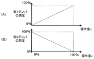
例えば図9(A)、(B)に示すように、第1ダンパ12Aの開度と操作量uとの関係、及び、第2ダンパ12Bの開度と操作量vとの関係を設定しておき、これらの関係に基づいて、第1ダンパ12A及び第2ダンパ12Bの開度を制御するようにすれば良い。
Next, the
For example, as shown in FIGS. 9A and 9B, the relationship between the opening degree of the
つまり、図9(A)に示すように、操作量uが0%の場合、第1ダンパ12Aが全閉(開度0%)になり、第1フィルタ5Aが完全に利用されないようにし、操作量uが0%から100%へ向けて大きくなるにしたがって、第1ダンパ12Aの開度が大きくなっていき、第1フィルタ5Aの利用率が高くなっていくようにする。そして、操作量uが100%の場合、第1ダンパ12Aが全開(開度100%)になり、第1フィルタ5Aが完全に利用されるようにする。
That is, as shown in FIG. 9A, when the operation amount u is 0%, the
一方、図9(B)に示すように、操作量vが0%の場合、第2ダンパ12Bが全開(開度100%)になり、第2フィルタ5Bが完全に利用されるようにし、操作量vが0%から100%へ向けて大きくなるにしたがって、第2ダンパ12Bの開度が小さくなっていき、第2フィルタ5Bの利用率が低くなっていくようにする。そして、操作量vが100%の場合、第2ダンパ12Bが全閉(開度0%)になり、第2フィルタ5Bが完全に利用されなくなるようにする。
On the other hand, as shown in FIG. 9B, when the operation amount v is 0%, the
そして、これらの関係に基づいて、塵埃量予測部17で予測した将来の室内塵埃量が、目標塵埃量設定部で設定された目標塵埃量以下になるように、第1ダンパ12A及び第2ダンパ12Bのそれぞれの操作量u、vを設定し、これらの操作量u、vに基づいて、第1ダンパ12A及び第2ダンパ12Bの開度を制御するようにすれば良い。
例えば、将来の室内塵埃量と目標塵埃量との差に応じて操作量u、vを変えるようにすれば良い。例えば、将来の室内塵埃量と目標塵埃量との差が第1の量以上である場合は、操作量u、vをいずれも0%にし、第1ダンパ12Aを全閉にし、第2ダンパ12Bを全開にして、第1フィルタ5Aよりも塵埃除去率が高い第2フィルタ5Bのみが完全に利用されるようにし、将来の室内塵埃量と目標塵埃量との差が第2の量以下である場合は、操作量u、vをいずれも100%にし、第1ダンパ12Aを全開にし、第2ダンパ12Bを全閉にして、第1フィルタ5Aのみが完全に利用されるようにすれば良い。そして、将来の室内塵埃量と目標塵埃量との差が第1の量と第2の量との間である場合は、将来の室内塵埃量と目標塵埃量との差が小さいほど操作量u、vを大きくしていくようにすれば良い。なお、ここでは、第1ダンパ12A及び第2ダンパ12Bの操作量を同じにしているが、異なる操作量に基づいて第1ダンパ12A及び第2ダンパ12Bの開度を制御するようにしても良い。また、将来の室内塵埃量と目標塵埃量とが一致するようにフィードバック制御するようにしても良い。
Based on these relationships, the
For example, the operation amounts u and v may be changed according to the difference between the future indoor dust amount and the target dust amount. For example, when the difference between the future indoor dust amount and the target dust amount is greater than or equal to the first amount, the operation amounts u and v are both 0%, the
また、塵埃量を計測するセンサ(塵埃量計測部)や大気物性量を計測するセンサを室内に設け、制御部14が、室内塵埃量の時系列データから予測した将来の室内塵埃量が目標塵埃量以下になるように第1ダンパ12A及び第2ダンパ12Bの開度(開口比率;開閉)を制御するようにしても良い。
また、上述の実施形態では、温湿度調整室1Bは、2つの外気取り込み口2A、2B、即ち、第1外気取り込み口2A及び第2外気取り込み口2Bを備え、これらの2つの外気取り込み口2A、2Bのそれぞれに、フィルタ5A、5B及びダンパ12A、12Bが設けられているが、これに限られるものではない。
Further, a sensor for measuring the amount of dust (dust amount measuring unit) and a sensor for measuring the amount of physical properties of the atmosphere are provided indoors, and the future indoor dust amount predicted by the
In the above-described embodiment, the temperature /
例えば、図10に示すように、温湿度調整室1Bは、1つの外気取り込み口2を備え、この外気取り込み口2に第1フィルタ5Aを設け、外気取り込み口2から温湿度調整室1Bに取り込まれた外気をサーバ室1A内に供給する供給口13(サーバ室1Aの吸気口13;サーバ室1Aの外気取り込み口)の一の領域(第1領域)に第1ダンパ12Aを設け、残りの領域(第2領域)に第2フィルタ5B及び第2ダンパ12Bを設けるようにしても良い。つまり、上述の実施形態のように、サーバ室1Aに外気を導入するのに、2つの外気取り込み口2A、2Bを並列に設けるのに代えて、このように、サーバ室1Aに外気を導入するのに、2つの外気取り込み口2、13を直列に設けても良い。この場合、上述の実施形態では、外気に含まれる塵埃を除去するのに2種類のフィルタ5A、5Bをそれぞれ別個独立に用いていたのに対し、ここでは、外気に含まれる塵埃を除去するのに2種類のフィルタ5A、5Bを段階的に用いることになる。このように構成する場合、まず、第1フィルタ5Aを用いて、外気に含まれる大きな塵埃を除去することになる。そして、さらに必要であれば、第1ダンパ12Aを閉じ、第2ダンパ12Bを開けて、第1フィルタ5Aよりも塵埃除去率の高い高性能な第2フィルタ5Bを用いて、外気に含まれる小さい塵埃を除去して、サーバ室1Aに外気を導入することになる。一方、必要がない場合は、第1ダンパ12Aを開け、第2ダンパ12Bを閉じて、第2フィルタ5Bを用いることなく、第1フィルタ5Aを用いて外気に含まれる大きな塵埃を除去するだけにして、サーバ室1Aに外気を導入することになる。
For example, as shown in FIG. 10, the temperature /
この場合、塵埃除去システム3は、第1フィルタ5Aが、外気取り込み口2に設けられており、第1ダンパ12Aが、外気取り込み口2から取り込まれた外気を室内1Aに供給する供給口13の第1領域に設けられており、第2フィルタ5B及び第2ダンパ12Bが、供給口13の第2領域に設けられており、第1ダンパ12Aの開度に応じて供給口13の第1領域が開けられて第1フィルタ5Aが利用され、第2ダンパ12Bの開度に応じて供給口13の第2領域が開けられて第1フィルタ5A及び第2フィルタ5Bが利用されるようになっていることになる。
In this case, in the
このほか、図10に示す構成のものにおいて、第1フィルタ5Aを外気取り込み口2に設けずに、供給口13に設けても良い。つまり、供給口13の全領域に第1フィルタ5Aを設け、供給口13の一の領域に第1ダンパ12Aを設け、残りの領域に第2フィルタ5B及び第2ダンパ12Bを設けても良い。また、温湿度調整室1Bは、1つの外気取り込み口2を備え、この外気取り込み口2にはフィルタを設けずに、外気取り込み口2から温湿度調整室1Bに取り込まれた外気をサーバ室1A内に供給する供給口13の一の領域に第1フィルタ5A及び第1ダンパ12Aを設け、残りの領域に第2フィルタ5B及び第2ダンパ12Bを設けるようにしても良い。また、温湿度調整室1Bは、1つの外気取り込み口2を備え、この外気取り込み口2の一の領域に第1フィルタ5A及び第1ダンパ12Aを設け、残りの領域に第2フィルタ5B及び第2ダンパ12Bを設けるようにしても良い。
In addition, in the configuration shown in FIG. 10, the first filter 5 </ b> A may be provided at the
なお、本発明は、上述した実施形態及び変形例に記載した構成に限定されるものではなく、本発明の趣旨を逸脱しない範囲で種々変形することが可能である。
以下、上述の実施形態及び変形例に関し、更に、付記を開示する。
(付記1)
外気に含まれる塵埃を除去する第1フィルタと、
外気に含まれる塵埃を除去し、前記第1フィルタよりも塵埃除去率が高い第2フィルタと、
前記第1フィルタを利用する場合に開けられる第1ダンパと、
前記第2フィルタを利用する場合に開けられる第2ダンパと、
前記第1ダンパ及び前記第2ダンパの開度を制御する制御部とを備え、
前記制御部が、塵埃量の時系列データから予測した将来の塵埃量に基づいて前記第1ダンパ及び前記第2ダンパの開度を制御することを特徴とする塵埃制御システム。
Note that the present invention is not limited to the configurations described in the above-described embodiments and modifications, and various modifications can be made without departing from the spirit of the present invention.
Hereinafter, additional notes will be disclosed regarding the above-described embodiment and modifications.
(Appendix 1)
A first filter for removing dust contained in the outside air;
A second filter that removes dust contained in the outside air and has a higher dust removal rate than the first filter;
A first damper that is opened when using the first filter;
A second damper that is opened when using the second filter;
A controller that controls the opening degree of the first damper and the second damper;
The dust control system, wherein the control unit controls the opening degree of the first damper and the second damper based on a future dust quantity predicted from time series data of the dust quantity.
(付記2)
前記制御部は、塵埃量の時系列データに含まれる塵埃量及び大気物性量に基づいて前記将来の塵埃量を予測することを特徴とする、付記1に記載の塵埃制御システム。
(付記3)
前記制御部は、塵埃量の時系列データに含まれる塵埃量、風速及び湿度に基づいて前記将来の塵埃量を予測することを特徴とする、付記1又は2に記載の塵埃制御システム。
(Appendix 2)
The dust control system according to
(Appendix 3)
The dust control system according to
(付記4)
前記制御部は、ステップワイズ法及び重回帰モデルを用いて前記将来の塵埃量を予測することを特徴とする、付記1〜3のいずれか1項に記載の塵埃制御システム。
(付記5)
前記制御部は、塵埃量の時系列データから予測した将来の塵埃量が判定基準塵埃量以上であるか否かに基づいて前記第1ダンパ及び前記第2ダンパの開度を制御することを特徴とする、付記1〜4のいずれか1項に記載の塵埃制御システム。
(Appendix 4)
The dust control system according to any one of
(Appendix 5)
The control unit controls the opening degree of the first damper and the second damper based on whether or not the future dust amount predicted from the time series data of the dust amount is equal to or larger than the determination reference dust amount. The dust control system according to any one of
(付記6)
前記制御部は、外気塵埃量の時系列データから予測した将来の外気塵埃量、前記第1フィルタの塵埃除去率及び前記第2フィルタの塵埃除去率に基づいて予測した将来の室内塵埃量が目標塵埃量以下になるように前記第1ダンパ及び前記第2ダンパの開度を制御することを特徴とする、付記1〜4のいずれか1項に記載の塵埃制御システム。
(Appendix 6)
The controller sets a future indoor dust amount predicted based on a future outside dust amount predicted from time series data of the outside air dust amount, a dust removal rate of the first filter, and a dust removal rate of the second filter. The dust control system according to any one of
(付記7)
前記第1フィルタ及び前記第1ダンパは、第1外気取り込み口に設けられており、
前記第2フィルタ及び前記第2ダンパは、第2外気取り込み口に設けられており、
前記第1ダンパの開度に応じて前記第1外気取り込み口が開けられて前記第1フィルタが利用され、
前記第2ダンパの開度に応じて前記第2外気取り込み口が開けられて前記第2フィルタが利用されるようになっていることを特徴とする、付記1〜6のいずれか1項に記載の塵埃制御システム。
(Appendix 7)
The first filter and the first damper are provided at a first outside air intake port,
The second filter and the second damper are provided in a second outside air intake port,
The first outside air intake port is opened according to the opening of the first damper, and the first filter is used.
7. The apparatus according to any one of
(付記8)
前記第1フィルタは、外気取り込み口に設けられており、
前記第1ダンパは、前記外気取り込み口から取り込まれた外気を室内に供給する供給口の第1領域に設けられており、
前記第2フィルタ及び前記第2ダンパは、前記供給口の第2領域に設けられており、
前記第1ダンパの開度に応じて前記供給口の第1領域が開けられて前記第1フィルタが利用され、
前記第2ダンパの開度に応じて前記供給口の第2領域が開けられて前記第1フィルタ及び前記第2フィルタが利用されるようになっていることを特徴とする、付記1〜6のいずれか1項に記載の塵埃制御システム。
(Appendix 8)
The first filter is provided at an outside air intake port,
The first damper is provided in a first region of a supply port for supplying outside air taken in from the outside air intake port into the room,
The second filter and the second damper are provided in a second region of the supply port,
The first filter is used by opening the first region of the supply port according to the opening of the first damper.
(付記9)
付記1〜8のいずれか1項に記載の塵埃制御システムと、
前記塵埃制御システムの前記第1フィルタ又は前記第2フィルタを介して取り込まれた外気を、電子機器へ向けて送風するファンとを備えることを特徴とする冷却システム。
(付記10)
付記1〜8のいずれか1項に記載の塵埃制御システムと、
電子機器と、
前記塵埃制御システムの前記第1フィルタ又は前記第2フィルタを介して取り込まれた外気を、前記電子機器へ向けて送風するファンとを備えることを特徴とする情報処理システム。
(Appendix 9)
The dust control system according to any one of
A cooling system comprising: a fan for blowing outside air taken in via the first filter or the second filter of the dust control system toward an electronic device.
(Appendix 10)
The dust control system according to any one of
Electronic equipment,
An information processing system comprising: a fan that blows outside air taken in via the first filter or the second filter of the dust control system toward the electronic device.
1 外気導入型データセンタ
1A サーバ室
1B 温湿度調整室
2 外気取り込み口
2A 第1外気取り込み口
2B 第2外気取り込み口
3 塵埃制御システム
4 循環ダンパ
5 フィルタ
5A 第1フィルタ
5B 第2フィルタ
6 ファンユニット
6A ファン
7 コールドアイル
8 サーバ(電子機器)
9 サーバラック
10 ホットアイル
11 排気口
12A 第1ダンパ
12B 第2ダンパ
13 吸気口
14 制御部
15 データ取得部
16 判定基準塵埃量設定部
17 塵埃量予測部
18 塵埃量判定部
19 ダンパ制御部
20 計測部
21 データベース
DESCRIPTION OF
DESCRIPTION OF
Claims (6)
外気に含まれる塵埃を除去し、前記第1フィルタよりも塵埃除去率が高い第2フィルタと、
前記第1フィルタを利用する場合に開けられる第1ダンパと、
前記第2フィルタを利用する場合に開けられる第2ダンパと、
前記第1ダンパ及び前記第2ダンパの開度を制御する制御部とを備え、
前記制御部が、塵埃量の時系列データから予測した将来の塵埃量に基づいて前記第1ダンパ及び前記第2ダンパの開度を制御することを特徴とする塵埃制御システム。 A first filter for removing dust contained in the outside air;
A second filter that removes dust contained in the outside air and has a higher dust removal rate than the first filter;
A first damper that is opened when using the first filter;
A second damper that is opened when using the second filter;
A controller that controls the opening degree of the first damper and the second damper;
The dust control system, wherein the control unit controls the opening degree of the first damper and the second damper based on a future dust quantity predicted from time series data of the dust quantity.
前記塵埃制御システムの前記第1フィルタ又は前記第2フィルタを介して取り込まれた外気を、電子機器へ向けて送風するファンとを備えることを特徴とする冷却システム。 The dust control system according to any one of claims 1 to 4,
A cooling system comprising: a fan for blowing outside air taken in via the first filter or the second filter of the dust control system toward an electronic device.
電子機器と、
前記塵埃制御システムの前記第1フィルタ又は前記第2フィルタを介して取り込まれた外気を、前記電子機器へ向けて送風するファンとを備えることを特徴とする情報処理システム。 The dust control system according to any one of claims 1 to 4,
Electronic equipment,
An information processing system comprising: a fan that blows outside air taken in via the first filter or the second filter of the dust control system toward the electronic device.
Priority Applications (1)
| Application Number | Priority Date | Filing Date | Title |
|---|---|---|---|
| JP2014164795A JP2016040697A (en) | 2014-08-13 | 2014-08-13 | Dust control system, cooling system and information processing system |
Applications Claiming Priority (1)
| Application Number | Priority Date | Filing Date | Title |
|---|---|---|---|
| JP2014164795A JP2016040697A (en) | 2014-08-13 | 2014-08-13 | Dust control system, cooling system and information processing system |
Publications (1)
| Publication Number | Publication Date |
|---|---|
| JP2016040697A true JP2016040697A (en) | 2016-03-24 |
Family
ID=55541012
Family Applications (1)
| Application Number | Title | Priority Date | Filing Date |
|---|---|---|---|
| JP2014164795A Withdrawn JP2016040697A (en) | 2014-08-13 | 2014-08-13 | Dust control system, cooling system and information processing system |
Country Status (1)
| Country | Link |
|---|---|
| JP (1) | JP2016040697A (en) |
Cited By (2)
| Publication number | Priority date | Publication date | Assignee | Title |
|---|---|---|---|---|
| CN109857230A (en) * | 2019-02-12 | 2019-06-07 | 杜都 | A kind of server heat sink of the network security with dedusting function |
| CN113482722A (en) * | 2021-07-14 | 2021-10-08 | 李芹 | Non-coal mine safety production risk prediction early warning platform |
-
2014
- 2014-08-13 JP JP2014164795A patent/JP2016040697A/en not_active Withdrawn
Cited By (3)
| Publication number | Priority date | Publication date | Assignee | Title |
|---|---|---|---|---|
| CN109857230A (en) * | 2019-02-12 | 2019-06-07 | 杜都 | A kind of server heat sink of the network security with dedusting function |
| CN109857230B (en) * | 2019-02-12 | 2020-11-17 | 北京神州数码云科信息技术有限公司 | Network security is with server heat abstractor that has dust removal function |
| CN113482722A (en) * | 2021-07-14 | 2021-10-08 | 李芹 | Non-coal mine safety production risk prediction early warning platform |
Similar Documents
| Publication | Publication Date | Title |
|---|---|---|
| US9110476B2 (en) | Controlled cooling of an electronic system based on projected conditions | |
| US9879926B2 (en) | Controlled cooling of an electronic system for reduced energy consumption | |
| US7657347B2 (en) | Temperature-based monitoring method and system for determining first and second fluid flow rates through a heat exchanger | |
| JP2020533547A (en) | Cooling unit energy optimization through smart supply air temperature setpoint control | |
| US20180295754A1 (en) | Effectiveness-weighted control of cooling system components | |
| US11039556B2 (en) | Data center cooling system | |
| CN110691491B (en) | Controlling and optimizing indirect evaporative cooling units for data center cooling | |
| CN106133462B (en) | Extreme value for controlling vapor compression system finds controller and method | |
| CN107223195A (en) | Variable air quantity for HVAC system is modeled | |
| US20190200489A1 (en) | Controlling operational parameters of a cooling unit | |
| US20170280594A1 (en) | Cooling device, control method and control program for same, and storage medium | |
| CN112772008B (en) | Method for balancing air flow in ceiling guided containment system | |
| Chen et al. | Fan-independent air balancing method based on computation model of air duct system | |
| CN110030681A (en) | Air conditioning control method, control device and air-conditioning | |
| US10154614B1 (en) | Air handling unit intake air preheat system and method | |
| JP2016040697A (en) | Dust control system, cooling system and information processing system | |
| WO2015171098A2 (en) | Managing airflow distribution through adaptive vent tiles | |
| JP2015162097A (en) | air-conditioning control system and air-conditioning control method | |
| JP6455937B2 (en) | Simulation apparatus, simulation method, and program | |
| JP6314533B2 (en) | Data center | |
| JP2018173864A (en) | Information processing system, information processing method, and program | |
| US8768519B2 (en) | Apparatus and method for controlling grille aperture ratios of a plurality of air transfer grilles | |
| WO2020003544A1 (en) | Server rack and method of cooling the same | |
| CN110030682A (en) | Air conditioning control method, control device and air-conditioning | |
| JP2018060271A (en) | Management device, control method of management device, control program of management device and information processing system |
Legal Events
| Date | Code | Title | Description |
|---|---|---|---|
| A621 | Written request for application examination |
Free format text: JAPANESE INTERMEDIATE CODE: A621 Effective date: 20170511 |
|
| A761 | Written withdrawal of application |
Free format text: JAPANESE INTERMEDIATE CODE: A761 Effective date: 20171225 |