JP2016032193A - Imaging apparatus - Google Patents
Imaging apparatus Download PDFInfo
- Publication number
- JP2016032193A JP2016032193A JP2014153611A JP2014153611A JP2016032193A JP 2016032193 A JP2016032193 A JP 2016032193A JP 2014153611 A JP2014153611 A JP 2014153611A JP 2014153611 A JP2014153611 A JP 2014153611A JP 2016032193 A JP2016032193 A JP 2016032193A
- Authority
- JP
- Japan
- Prior art keywords
- unit
- image data
- instruction
- composition
- image
- Prior art date
- Legal status (The legal status is an assumption and is not a legal conclusion. Google has not performed a legal analysis and makes no representation as to the accuracy of the status listed.)
- Pending
Links
Images


Abstract
Description
本発明は、自分撮りが可能な撮像装置に関するものである。 The present invention relates to an imaging apparatus capable of taking a selfie.
従来、撮影レンズの撮影方向に表示部の表示方向を揃える機構を有する撮像装置が存在する(例えば、特許文献1参照)。この撮像装置によれば、表示部で構図を確認しながら自分撮り撮影を行うことができる。 2. Description of the Related Art Conventionally, there is an imaging apparatus having a mechanism that aligns the display direction of a display unit with the shooting direction of a shooting lens (for example, see Patent Document 1). According to this imaging apparatus, self-portrait photography can be performed while confirming the composition on the display unit.
しかし、上述の撮像装置においては、操作者が表示部を見ながら撮影を行うため、視線が逸れた画像が取得されるという問題がある。 However, in the above-described imaging device, there is a problem that an image with a line of sight is acquired because the operator performs shooting while looking at the display unit.
また、操作者が表示部で構図を確認した後に視線を撮影レンズの方向に移して撮影を行った場合、視線を撮影レンズの方向に移すまでの間に撮像装置の位置がずれ、当初決定した構図の通りに撮影できない場合がある。特に、自分撮りでは撮影距離が近いため、撮像装置の位置が少しずれただけでも構図が大きく変化するおそれがある。 In addition, when the operator checks the composition on the display unit and moves the line of sight in the direction of the photographic lens, the position of the imaging device is shifted until the line of sight is moved in the direction of the photographic lens. Shooting may not be possible according to the composition. In particular, since the shooting distance is short in self-portrait, the composition may change greatly even if the position of the imaging device is slightly shifted.
本発明の目的は、視線が逸れていない適切な構図の画像を取得することができる撮像装置を提供することである。 An object of the present invention is to provide an imaging apparatus capable of acquiring an image with an appropriate composition in which the line of sight is not deviated.
本発明の撮像装置は、被写体光を撮像する撮像素子と、前記撮像素子から出力される画像データに基づいて、スルー画像の表示を行う表示部と、操作者が前記表示部に表示される前記スルー画像の構図を確認しながら自分を撮影する自分撮りモードを設定する設定部と、前記設定部により前記自分撮りモードが設定された場合に前記画像データから所定の領域の領域画像データを抽出する抽出部と、前記領域画像データに基づく領域画像を前記表示部に表示する表示制御部と、第1の指示を行う第1指示部と、前記第1指示部により前記第1の指示がなされた場合に、前記領域画像の構図補正を開始する構図補正部と、第2の指示を行う第2指示部と、前記第2指示部により前記第2の指示がなされた際に前記構図補正がなされた前記領域画像の前記領域画像データを記憶する記憶部とを備えることを特徴とする。 The imaging device of the present invention includes an imaging element that captures subject light, a display unit that displays a through image based on image data output from the imaging element, and an operator that is displayed on the display unit. A setting unit that sets a self-portrait mode in which the user takes a picture while confirming the composition of the through image; and when the self-portrait mode is set by the setting unit, area image data of a predetermined area is extracted from the image data An extraction unit, a display control unit that displays a region image based on the region image data on the display unit, a first instruction unit that issues a first instruction, and the first instruction unit that gives the first instruction The composition correction unit that starts composition correction of the region image, the second instruction unit that performs a second instruction, and the composition correction performed when the second instruction is given by the second instruction unit. The area picture Characterized in that it comprises a storage unit for storing the region image data.
本発明によれば、視線が逸れていない適切な構図の画像を取得することができる。 According to the present invention, it is possible to acquire an image with an appropriate composition in which the line of sight is not deviated.
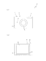
以下、図面を参照して実施の形態に係るデジタルカメラについて説明する。図1(a)は、実施の形態に係るデジタルカメラを正面から視た図であり、図1(b)は、これを背面から視た図である。デジタルカメラ2は、金属やプラスチック等により形成された筐体4を備え、筐体4の前面には、被写体光を撮像素子53(図3参照)に導く撮影レンズ5、LED光を発光するLED6、及びフラッシュ窓7が設けられている。また、筐体4の上面には、電源スイッチ8、及びシャッタボタン10が設けられている。
Hereinafter, a digital camera according to an embodiment will be described with reference to the drawings. FIG. 1A is a view of the digital camera according to the embodiment as viewed from the front, and FIG. 1B is a view of the digital camera as viewed from the back. The
また、筐体4の背面には、LCD表示部12に画像を表示する液晶モニタ13が収納されている。ここで、液晶モニタ13は、図示しない2軸回動機構を介して筐体4から回動可能に支持されている。なお、図1(b)は、LCD表示部12の位置が筐体4の背面に来るように液晶モニタ13を折り畳んだ、閉じた状態を示している。
In addition, a
図2は、液晶モニタ13を筐体4の背面から起こしてLCD表示部12の向きを撮影方向(筐体4の前面側)に向けた、開いた状態を示す図である。操作者は、図2に示すように、液晶モニタ13を開いた状態とすることにより、LCD表示部12で構図を確認しながら自分自身を撮影する自分撮りを行うことができる。
FIG. 2 is a diagram illustrating an open state in which the
図3は、実施の形態に係るデジタルカメラ2のシステム構成を示すブロック図である。デジタルカメラ2は、CPU24を備え、CPU24には、操作部26、LCD表示部12の表示制御を行う表示制御部30、液晶モニタ13が開いた状態となったことを検知する検知部33、被写体を撮影するための撮影部34、撮影部34により撮影された画像データを一時的に記憶する画像記憶部36、水平面に対するデジタルカメラ2の傾斜角度を計測する傾斜角センサ38、LED6の点滅を制御する照明制御部40、画像データから人物の顔を認識する顔認識部42、シャッタボタン10が半押しされた際の構図を記憶する構図記憶部44、音声を出力するスピーカ45、及び画像データを記憶するメモリカード46を装着するメモリカードスロット48が接続されている。
FIG. 3 is a block diagram showing a system configuration of the
ここで、操作部26には、電源スイッチ8、シャッタボタン10、シャッタボタンを半押し位置まで押下することによりオンされるスイッチS1(図示せず)、シャッタボタンの全押しによりオンされるスイッチS2(図示せず)等が含まれている。また、撮影部34は、レンズ51の駆動制御を行うレンズ駆動部52、CCD等により構成される撮像素子53、レンズ駆動部52及び撮像素子53の駆動制御を行う撮影制御部54を備えている。
Here, the
図4は、実施の形態に係るデジタルカメラ2における自分撮りモードの処理を示すフローチャートである。まず、電源がオンにされると、CPU24は、撮像素子53によりスルー画像の撮影を開始し、撮像素子53により撮像された画像データを順次画像記憶部36に記憶する。次に、画像記憶部36から画像データを読み出し、画像データに基づくスルー画像をLCD表示部12に表示する(ステップS1)。
FIG. 4 is a flowchart showing processing in the self-portrait mode in the
ここで、操作者が、図2に示すように液晶モニタ13を回動させて開いた状態にすると、CPU24は、検知部33により液晶モニタ13が開いた状態にされたことを検知し(ステップS2)、デジタルカメラ2の撮影モードを自分撮りモードに移行する(ステップS3)。
Here, when the operator turns the
自分撮りモードに移行すると、CPU24は、撮影制御部54により、レンズ駆動部52を駆動してレンズ51を光軸方向に移動させ、広角で撮影ができるように撮影部34の撮影画角を調整する(ステップS4)。
When shifting to the self-portrait mode, the
次に、CPU24は、図5に示すように、画像記憶部36から順次読み出される画像データ60から所定の抽出領域の領域画像データ62を抽出し(ステップS5)、領域画像データ62に基づくスルー画像をLCD表示部12に拡大して表示する。また、CPU24は、顔認識部42により領域画像データ62に含まれる人物像の顔の位置の認識を開始する(ステップS6)。
Next, as shown in FIG. 5, the
ここで、操作者はLCD表示部12に表示されているスルー画像を見ながらデジタルカメラ2の位置や向きを調整する。そして、自分の顔が適切な構図でLCD表示部12に表示された時点でシャッタボタン10を半押しする。
Here, the operator adjusts the position and orientation of the
シャッタボタン10が半押しされ、スイッチS1がオンにされると(ステップS7)、CPU24は、顔認識部42により認識された顔の位置に基づいて画像の構図を決定し(ステップS8)、決定した構図を構図補正の基準となる基準構図として構図記憶部44に記憶する。次に、CPU24は、「レンズを見てシャッターを押してください。」等の視線を撮影レンズ5に移すように促すメッセージをLCD表示部12に表示する。
When the
次に、CPU24は、構図記憶部44に記憶された基準構図を参照し、常時領域画像データ62に基づく画像の構図が基準構図と同じ構図になるように構図補正を行う(ステップS9)。例えば、操作者の手がぶれてデジタルカメラ2が移動し、画像データ60における顔の位置が変化したとする。この場合、CPU24は、図6に示すように、スルー画像としてLCD表示部12に表示される顔の位置が基準構図における顔の位置と同じ位置になるように、領域画像データ62の抽出領域を移動させる。
Next, the
これにより、操作者の手がぶれるなどしてデジタルカメラ2が移動した場合であっても、操作者がシャッタボタン10を半押しした時点の構図がスルー画像としてLCD表示部12に表示され続ける。
As a result, even when the
この間、操作者は、LCD表示部12を見ていた視線を撮影レンズ5に移し、撮影レンズ5を見ながらシャッタボタン10を全押しする。シャッタボタン10が全押しされ、スイッチS2がオンにされると(ステップS10)、CPU24は、この時点で画像データ60から抽出された領域画像データ62をメモリカード46に記憶する(ステップS11)。
During this time, the operator moves the line of sight of the
本実施の形態に係るデジタルカメラ2によれば、操作者は、LCD表示部12を見ながら構図を決定した後に視線を撮影レンズ5に移して自分自身の画像を撮影できるため、視線が逸れていない適切な構図の画像を取得することができる。また、シャッタボタン10が半押しされるとその時点の構図が記憶され、LCD表示部12に表示される画像が記憶された構図と同じ構図になるように構図補正されるため、シャッタボタン10を半押しして構図を決定してからシャッタボタン10を全押しして撮影を行うまでの間に操作者の手がぶれた場合でも、決定した構図のフレーミング状態を維持することができる。
According to the
なお、上述の実施の形態において、構図補正で補正しきれない構図変化があった場合にはその旨を警告してもよい。例えば、操作者がデジタルカメラ2を左方向に移動させ、図7(a)に示すように、領域画像データ62の縁部が画像データ60の縁部と接したとする。この場合、CPU24は、図7(b)に示すように、右矢印のアイコンを青色で表示すると共にLED6を2Hzで点滅させ、操作者にデジタルカメラ2を右方向にずらすように促す。
In the above-described embodiment, if there is a composition change that cannot be corrected by composition correction, a warning to that effect may be given. For example, it is assumed that the operator moves the
ここで、操作者が更にデジタルカメラ2を左方向に移動させ、図8(a)に示すように、領域画像データ62が画像データ60からフレームアウトした場合、CPU24は、図8(b)に示すように、右矢印のアイコンを赤色で表示すると共に、LED6を8Hzで点滅させる。このように、構図補正の限界に達した場合、及び構図補正の限界を超えた場合の2段階で警告を行うことにより、操作者が構図補正の限界を超えてデジタルカメラ2を移動させることを確実に防止することができる。なお、警告の際には、LED6の点滅に代えて、またはLED6の点滅と共にスピーカ45からBeep音を出力してもよい。
Here, when the operator further moves the
また、上述の実施の形態において、デジタルカメラ2の移動量に基づいて構図補正を行ってもよい。例えば、自分撮りモードに移行すると、CPU24は、傾斜角センサ38によりデジタルカメラ2の傾斜角度の計測を開始する。次に、シャッタボタン10が半押しされると、CPU24は、傾斜角センサ38から出力される検出信号を用いてデジタルカメラ2の移動量を計測する。具体的には、所定の時間内における、光軸方向、筐体4の短手方向(上下方向)、筐体4の長手方向(左右方向)の移動の移動量をそれぞれ計測する。
In the above-described embodiment, composition correction may be performed based on the movement amount of the
次に、CPU24は、計測した移動量に基づいてLCD表示部12に表示される画像の構図補正を行う。例えば、図9(a)に示すように、操作者がデジタルカメラ2を所定の距離ある方向に移動させ、撮影部34によって撮影される範囲がデジタルカメラ2の移動に伴って変化したとする。この場合、CPU24は、図9(b)に示すように、画像データ60から抽出する領域画像データ62の抽出領域を、デジタルカメラ2の移動量に対応する距離分デジタルカメラ2の移動方向と反対方向に移動させる。
Next, the
なお、デジタルカメラ2の移動量に基づく構図補正は、顔の位置に基づく構図補正と併せて行ってもよい。また、デジタルカメラ2の移動量を計測することに代えて、撮像素子53により所定の時間間隔を置いて撮像された画像データを比較することにより動きベクトルを生成してもよい。そして、動きベクトルに基づいて領域画像データ62の抽出領域を移動させる構図補正を行ってもよい。
The composition correction based on the movement amount of the
また、上述の実施の形態において、自分撮りモードに移行した際に、人物の顔を中心とする所定の抽出領域の領域画像データを画像データから抽出してもよい。この場合、シャッタボタン10が半押しされると、CPU24は、人物の顔が中心となる構図を基準構図として構図記憶部44に記憶し、常時人物の顔が中心に位置するように構図補正を行う。これにより、操作者は、スルー画像に表示される自分の顔の位置を調整することなく容易に構図を決定することができる。また、自分の顔が中央に位置する適切な構図の画像を取得することができる。
In the above-described embodiment, region image data of a predetermined extraction region centered on a person's face may be extracted from image data when the mode is shifted to the self-portrait mode. In this case, when the
なお、画像データから複数の人物の顔が認識された場合には、図10(a)に示すように、複数の人物の顔の中心部を含む領域画像データ82を画像データ80から抽出し、図10(b)に示すように、領域画像データ82に基づく画像をスルー画像としてLCD表示部12に表示してもよい。
When a plurality of human faces are recognized from the image data,
また、上述の実施の形態において、人物の顔の大きさに基づいて構図補正を行ってもよい。例えば、自分撮りモードに移行すると、CPU24は、顔認識部42により領域画像データに含まれる顔の大きさの認識を開始する。ここで、操作者は、デジタルカメラ2を光軸方向に移動させ、自分の顔が所望の大きさでLCD表示部12に表示された時点でシャッタボタン10を半押しする。
In the above-described embodiment, composition correction may be performed based on the size of a person's face. For example, when shifting to the self-portrait mode, the
シャッタボタン10が半押しされると、CPU24は、顔認識部42により認識された顔の大きさに基づいて画像の構図を決定し、決定した構図を構図補正の基準となる基準構図として構図記憶部44に記憶する。次に、CPU24は、常時領域画像データに含まれる顔の大きさが構図記憶部44に記憶された顔の大きさと同じ大きさになるように領域画像データの抽出領域の大きさを変更する構図補正を行う。これにより、デジタルカメラ2が光軸方向に移動し、撮像素子53によって撮像された画像データ60に含まれる顔の大きさが変化した場合においても、顔が適切な大きさで表示された画像を取得することができる。
When the
なお、図11(a)、(b)に示すように、認識された顔の周囲に顔枠74を表示する場合、顔の大きさに合わせて顔枠74の大きさを変更してもよい。また、顔の大きさに基づく構図補正は、顔の位置に基づく構図補正と併せて行ってもよい。また、人物の顔の大きさに基づく構図補正は、レンズ駆動部52を駆動してレンズ51を光軸方向に移動させ、画像データ60に含まれる被写体像の大きさを変化させることにより行ってもよい。
As shown in FIGS. 11A and 11B, when the
また、上述の実施の形態において、領域画像データに含まれる人物像に特定の動作変化があったか否かを検出するようにしてもよい。例えば、操作者がVサインを出し、領域画像データに含まれる人物像がVサインを出した人物像に変化したとする。この場合、CPU24は、この動作変化を検出することによりスイッチS1をオンにして構図を決定し、基準構図として構図記憶部44に記憶する。次に、CPU24は、再度領域画像データに含まれる人物像がVサインを出した人物像に変化したか否かの検出を開始する。
Further, in the above-described embodiment, it may be detected whether or not a specific image change has occurred in the person image included in the area image data. For example, it is assumed that the operator gives a V-sign and the person image included in the area image data changes to a person image that gives a V-sign. In this case, the
ここで、操作者が再度Vサインを出し、領域画像データに含まれる人物像がVサインを出した人物像に変化したことを検出すると、CPU24は、スイッチS2をオンにし、スイッチS2をオンにした時点で抽出された領域画像データをメモリカード46に記憶する。このように、シャッタボタン10を操作することなくスイッチS1及びスイッチS2をオンにすることにより、シャッタボタン10を操作した際に手がぶれて決定した構図通りの画像が取得できなくなることを防止することができる。
Here, when the operator issues the V sign again and detects that the person image included in the area image data has changed to the person image having the V sign, the
また、この場合、デジタルカメラに更にタイマーを備えるようにし、スイッチS1がオンにされてから所定の時間が経過した場合にスイッチS2をオンにしてもよい。また、人物像が所定の時間を超えて変化しない場合、構図が決定されたものとみなしスイッチS1をオンにするようにしてもよい。 In this case, the digital camera may further include a timer, and the switch S2 may be turned on when a predetermined time has elapsed since the switch S1 was turned on. If the person image does not change over a predetermined time, it may be assumed that the composition has been determined and the switch S1 is turned on.
また、上述の実施の形態において、一般的に知られている視線検出技術を用いて、領域画像データから人物の視線を検出するようにしてもよい。例えば、スイッチS1がオンにされると、CPU24は、領域画像データの抽出を開始すると共に、領域画像データから人物の視線を検出する。ここで、領域画像データから人物の視線が検出され、人物の視線が撮影レンズ5を向いていることが確認された場合、CPU24は、スイッチS2をオンにする。これにより、操作者がLCD表示部12を見ていた視線を撮影レンズ5に移した時点で撮影が行われるため、操作者は、確実に視線の逸れていない画像を取得することができる。
In the above-described embodiment, a person's line of sight may be detected from the region image data using a generally known line-of-sight detection technique. For example, when the switch S1 is turned on, the
また、上述の実施の形態において、自分撮りモードを設定するためのモードボタンを設け、操作者によりモードボタンが操作された場合にデジタルカメラ2の撮影モードを自分撮りモードに移行してもよい。
In the above-described embodiment, a mode button for setting the self-shooting mode may be provided, and the shooting mode of the
また、上述の実施の形態において、スイッチS2がオンにされた場合に動画の撮影を開始してもよい。この場合、CPU24は、シャッタボタン10が全押しされると、領域画像データに基づく画像を順次LCD表示部12に画像を表示すると共に、LCD表示部12に表示された領域画像データを順次メモリカード46に記憶する。
In the above-described embodiment, moving image shooting may be started when the switch S2 is turned on. In this case, when the
また、上述の実施の形態においては、撮像装置として2軸回動機構を備えるデジタルカメラ2を用いる場合を例に説明したが、2軸回動機構を備えない他のデジタルカメラ、スマートホン、タブレット端末、携帯電話等の撮像装置においても、スルー画像の画像データからの領域画像データの抽出し、スイッチS1がオンにされた場合に構図補正を開始し、スイッチS2がオンにされた際に領域画像データを記憶するプログラムを備えている場合には本発明を適用することができる。
In the above-described embodiment, the case where the
また、上述の実施の形態において、液晶モニタ13は、電源をオンにする前に開いた状態にされていてもよい。この場合、電源がオンにされた時点で、検知部33により液晶モニタ13が開いた状態にされたことが検知され、デジタルカメラ2の撮影モードが自分撮りモードに移行される。
In the above-described embodiment, the liquid crystal monitor 13 may be opened before the power is turned on. In this case, when the power is turned on, the
2…デジタルカメラ、6…LED、12…LCD表示部、13…液晶モニタ、24…CPU、26…操作部、33…検知部、38…傾斜角センサ、42…顔認識部、44…構図記憶部、45…スピーカ、53…撮像素子
DESCRIPTION OF
Claims (11)
前記撮像素子から出力される画像データに基づいて、スルー画像の表示を行う表示部と、
操作者が前記表示部に表示される前記スルー画像の構図を確認しながら自分を撮影する自分撮りモードを設定する設定部と、
前記設定部により前記自分撮りモードが設定された場合に前記画像データから所定の領域の領域画像データを抽出する抽出部と、
前記領域画像データに基づく領域画像を前記表示部に表示する表示制御部と、
第1の指示を行う第1指示部と、
前記第1指示部により前記第1の指示がなされた場合に、前記領域画像の構図補正を開始する構図補正部と、
第2の指示を行う第2指示部と、
前記第2指示部により前記第2の指示がなされた際に前記構図補正がなされた前記領域画像の前記領域画像データを記憶する記憶部と
を備えることを特徴とする撮像装置。 An image sensor for imaging subject light;
A display unit for displaying a through image based on image data output from the image sensor;
A setting unit for setting a self-portrait mode in which an operator shoots himself while confirming the composition of the through image displayed on the display unit;
An extraction unit that extracts region image data of a predetermined region from the image data when the selfie mode is set by the setting unit;
A display control unit for displaying a region image based on the region image data on the display unit;
A first instruction unit for giving a first instruction;
A composition correction unit that starts composition correction of the region image when the first instruction is given by the first instruction unit;
A second instruction unit for giving a second instruction;
An image pickup apparatus comprising: a storage unit that stores the region image data of the region image that has undergone the composition correction when the second instruction is given by the second instruction unit.
前記第1の指示がなされた場合に前記顔認識部より認識された人物の顔の位置、及び大きさの少なくとも一方に基づいて、構図補正の基準となる基準構図を決定する決定部と
を備え、
前記構図補正部は、前記領域画像の構図が前記基準構図と同じ構図になるように、前記抽出部により抽出される前記領域画像データの前記所定の領域の位置、及び大きさの少なくとも一方を変更することを特徴とする請求項1記載の撮像装置。 A face recognition unit for recognizing at least one of the position and size of a human face from the region image data;
A determination unit that determines a reference composition that serves as a reference for composition correction based on at least one of the position and size of the face of the person recognized by the face recognition unit when the first instruction is given; ,
The composition correction unit changes at least one of the position and the size of the predetermined region of the region image data extracted by the extraction unit so that the composition of the region image becomes the same composition as the reference composition. The imaging apparatus according to claim 1, wherein:
前記構図補正部は、前記移動検出部により検出された移動量に基づいて、前記抽出部により抽出される前記領域画像データの前記所定の領域を変更することを特徴とする請求項1または2記載の撮像装置。 A movement detection unit for detecting the movement amount of the imaging device;
The composition correction unit changes the predetermined region of the region image data extracted by the extraction unit based on a movement amount detected by the movement detection unit. Imaging device.
前記設定部は、前記表示部の表示面が開状態とされた場合に前記自分撮りモードを設定することを特徴とする請求項1〜4の何れか一項に記載の撮像装置。 A support unit that rotatably supports the display unit in a closed state in which the display unit is housed in the back surface of the imaging apparatus or an open state in which the display surface of the display unit is directed in the shooting direction;
The imaging device according to claim 1, wherein the setting unit sets the self-portrait mode when a display surface of the display unit is in an open state.
前記第1指示部は、前記動作検出部により前記領域画像データに含まれる前記人物像に前記特定の動作変化があったことが検出された場合に前記第1の指示を行い、
前記第2指示部は、前記動作検出部により前記領域画像データに含まれる前記人物像に前記特定の動作変化があったことが検出された場合、または、前記動作検出部により前記特定の動作変化あったことが検出されてから所定の時間が経過した場合に前記第2の指示を行うことを特徴とする請求項1〜5の何れか一項に記載の撮像装置。 A motion detection unit that detects that a specific motion change has occurred in the human image included in the region image data;
The first instruction unit performs the first instruction when it is detected by the motion detection unit that the specific motion change has occurred in the person image included in the region image data,
The second instruction unit is configured to detect that the specific motion change is detected by the motion detection unit when the motion detection unit detects that the human image included in the region image data has the specific motion change. The imaging apparatus according to any one of claims 1 to 5, wherein the second instruction is performed when a predetermined time has elapsed since it was detected.
前記第2指示部は、前記視線検出部により人物の視線が検出された場合に前記第2の指示を行うことを特徴とする請求項1〜5の何れか一項に記載の撮像装置。 A line-of-sight detection unit that detects the line of sight of a person from the area image data;
6. The imaging apparatus according to claim 1, wherein the second instruction unit performs the second instruction when a line of sight of a person is detected by the line-of-sight detection unit.
Priority Applications (1)
| Application Number | Priority Date | Filing Date | Title |
|---|---|---|---|
| JP2014153611A JP2016032193A (en) | 2014-07-29 | 2014-07-29 | Imaging apparatus |
Applications Claiming Priority (1)
| Application Number | Priority Date | Filing Date | Title |
|---|---|---|---|
| JP2014153611A JP2016032193A (en) | 2014-07-29 | 2014-07-29 | Imaging apparatus |
Publications (2)
| Publication Number | Publication Date |
|---|---|
| JP2016032193A true JP2016032193A (en) | 2016-03-07 |
| JP2016032193A5 JP2016032193A5 (en) | 2017-09-07 |
Family
ID=55442340
Family Applications (1)
| Application Number | Title | Priority Date | Filing Date |
|---|---|---|---|
| JP2014153611A Pending JP2016032193A (en) | 2014-07-29 | 2014-07-29 | Imaging apparatus |
Country Status (1)
| Country | Link |
|---|---|
| JP (1) | JP2016032193A (en) |
Cited By (2)
| Publication number | Priority date | Publication date | Assignee | Title |
|---|---|---|---|---|
| WO2017203644A1 (en) * | 2016-05-25 | 2017-11-30 | 日立マクセル株式会社 | Information processing device, support device for information processing device, and control program for support device for information processing device |
| WO2021137584A1 (en) * | 2019-12-30 | 2021-07-08 | 삼성전자 주식회사 | Moving image processing method and electronic device for supporting same |
Citations (5)
| Publication number | Priority date | Publication date | Assignee | Title |
|---|---|---|---|---|
| JPH03132732A (en) * | 1989-10-19 | 1991-06-06 | Asahi Optical Co Ltd | Automatic focusing camera |
| JP2006261783A (en) * | 2005-03-15 | 2006-09-28 | Olympus Imaging Corp | Image sensing device |
| JP2006319610A (en) * | 2005-05-12 | 2006-11-24 | Matsushita Electric Ind Co Ltd | Camera |
| JP2008028747A (en) * | 2006-07-21 | 2008-02-07 | Casio Comput Co Ltd | Imaging device and program thereof |
| JP2014050022A (en) * | 2012-09-03 | 2014-03-17 | Nikon Corp | Image processing device, imaging device, and program |
-
2014
- 2014-07-29 JP JP2014153611A patent/JP2016032193A/en active Pending
Patent Citations (5)
| Publication number | Priority date | Publication date | Assignee | Title |
|---|---|---|---|---|
| JPH03132732A (en) * | 1989-10-19 | 1991-06-06 | Asahi Optical Co Ltd | Automatic focusing camera |
| JP2006261783A (en) * | 2005-03-15 | 2006-09-28 | Olympus Imaging Corp | Image sensing device |
| JP2006319610A (en) * | 2005-05-12 | 2006-11-24 | Matsushita Electric Ind Co Ltd | Camera |
| JP2008028747A (en) * | 2006-07-21 | 2008-02-07 | Casio Comput Co Ltd | Imaging device and program thereof |
| JP2014050022A (en) * | 2012-09-03 | 2014-03-17 | Nikon Corp | Image processing device, imaging device, and program |
Cited By (2)
| Publication number | Priority date | Publication date | Assignee | Title |
|---|---|---|---|---|
| WO2017203644A1 (en) * | 2016-05-25 | 2017-11-30 | 日立マクセル株式会社 | Information processing device, support device for information processing device, and control program for support device for information processing device |
| WO2021137584A1 (en) * | 2019-12-30 | 2021-07-08 | 삼성전자 주식회사 | Moving image processing method and electronic device for supporting same |
Similar Documents
| Publication | Publication Date | Title |
|---|---|---|
| JP2008118276A (en) | Mobile equipment with camera and photography assisting method therefor | |
| JP4802058B2 (en) | Mobile phone with camera and imaging method thereof | |
| KR20140121695A (en) | Image photographing apparatus and method for controlling the same | |
| JP5923759B2 (en) | Imaging device | |
| JP2008205569A (en) | Imaging apparatus and method | |
| JP2013179536A (en) | Electronic apparatus and control method therefor | |
| JP6389342B2 (en) | Imaging apparatus and control method thereof | |
| JP2009033237A (en) | Electronic camera | |
| JP2016032193A (en) | Imaging apparatus | |
| WO2017086300A1 (en) | Imaging device and control method therefor, and operation program | |
| US20130293682A1 (en) | Image capture device, image capture method, and program | |
| US10634976B2 (en) | Imaging device | |
| JP2014140214A (en) | Image pickup device and image pickup method | |
| JP5572564B2 (en) | Imaging apparatus and display control method thereof | |
| JP5504741B2 (en) | Imaging device | |
| JP2008083078A (en) | Camera | |
| TW201518839A (en) | Portable electronic device and method of light compensating for image extraction | |
| JP4315773B2 (en) | Cameras and accessories | |
| JP6270508B2 (en) | Imaging apparatus and image display method of imaging apparatus | |
| JP2013176060A (en) | Imaging apparatus and imaging apparatus control method | |
| JP2005257869A (en) | Imaging apparatus | |
| JP2009159394A (en) | Electronic equipment | |
| JP2013162364A (en) | Imaging apparatus, control method and program therefor, and recording medium | |
| JP5963890B2 (en) | IMAGING DEVICE, IMAGING DEVICE CONTROL METHOD, AND IMAGING DEVICE MODE SWITCHING PROGRAM | |
| JP2012009959A (en) | Imaging apparatus, imaging method, and image conversion program |
Legal Events
| Date | Code | Title | Description |
|---|---|---|---|
| A521 | Request for written amendment filed |
Free format text: JAPANESE INTERMEDIATE CODE: A523 Effective date: 20170728 |
|
| A621 | Written request for application examination |
Free format text: JAPANESE INTERMEDIATE CODE: A621 Effective date: 20170728 |
|
| A131 | Notification of reasons for refusal |
Free format text: JAPANESE INTERMEDIATE CODE: A131 Effective date: 20180828 |
|
| A02 | Decision of refusal |
Free format text: JAPANESE INTERMEDIATE CODE: A02 Effective date: 20190319 |