JP2016031435A - Developing device, process cartridge, and image forming apparatus - Google Patents

Developing device, process cartridge, and image forming apparatus Download PDF

Info

Publication number
JP2016031435A
JP2016031435A JP2014153161A JP2014153161A JP2016031435A JP 2016031435 A JP2016031435 A JP 2016031435A JP 2014153161 A JP2014153161 A JP 2014153161A JP 2014153161 A JP2014153161 A JP 2014153161A JP 2016031435 A JP2016031435 A JP 2016031435A
Authority
JP
Japan
Prior art keywords
developing
developing sleeve
developing device
developer
recesses
Prior art date
Legal status (The legal status is an assumption and is not a legal conclusion. Google has not performed a legal analysis and makes no representation as to the accuracy of the status listed.)
Pending
Application number
JP2014153161A
Other languages
Japanese (ja)
Inventor
寺井 純一
Junichi Terai
純一 寺井
小川 禎史
Sadafumi Ogawa
禎史 小川
馬淵 裕之
Hiroyuki Mabuchi
裕之 馬淵
幸雄 乙▲め▼
Yukio Otome
幸雄 乙▲め▼
菊地 裕
Yutaka Kikuchi
裕 菊地
彰 藤森
Akira Fujimori
彰 藤森
啓明 岡本
Hiroaki Okamoto
啓明 岡本
篤 中本
Atsushi Nakamoto
篤 中本
Current Assignee (The listed assignees may be inaccurate. Google has not performed a legal analysis and makes no representation or warranty as to the accuracy of the list.)
Ricoh Co Ltd
Original Assignee
Ricoh Co Ltd
Priority date (The priority date is an assumption and is not a legal conclusion. Google has not performed a legal analysis and makes no representation as to the accuracy of the date listed.)
Filing date
Publication date
Application filed by Ricoh Co Ltd filed Critical Ricoh Co Ltd
Priority to JP2014153161A priority Critical patent/JP2016031435A/en
Publication of JP2016031435A publication Critical patent/JP2016031435A/en
Pending legal-status Critical Current

Links

Images

Abstract

PROBLEM TO BE SOLVED: To provide a developing device that can prevent the occurrence of unevenness in image density even when a DA sleeve is used as a developing sleeve of a developer carrier used for a multistage developing system, and an image forming apparatus using the same.SOLUTION: There is provided a developing device 113 including a plurality of developer carriers 99 and 115 that each have a developing sleeve 132 and are arranged in proximity and opposite to each other; the developing sleeve 132 has a plurality of recesses 139 provided on the outer surface regularly or irregularly at intervals so as not to be overlapped in plan view; the recesses 139 are formed inclined with respect to the shaft center of the developing sleeve 132, and are formed such that the directions of inclination of the recesses 139 are in the opposite directions to each other at a part where the adjacent developer carriers 99 and 115 are arranged in proximity and opposite to each other.SELECTED DRAWING: Figure 27

Description

本発明は、複写機、ファクシミリ、スキャナ等の電子写真式画像形成装置に関し、詳しくは現像装置の構成に関する。   The present invention relates to an electrophotographic image forming apparatus such as a copying machine, a facsimile, and a scanner, and more particularly to a configuration of a developing device.

画像形成装置の現像装置として、潜像担持体に対向配置された複数の現像剤担持体表面に担持した2成分現像剤により、潜像担持体の表面に形成された静電潜像に対して重複した現像処理を行うものが知られている。このように同一の静電潜像に対して複数の現像剤担持体により現像処理を段階的に行う現像方式は「多段現像方式」と呼ばれ、特にプロセス線速が速い高速の画像形成装置に多く採用されている。なお、多段現像方式とは、2段階以上で現像処理を行うものである。   As a developing device for an image forming apparatus, an electrostatic latent image formed on the surface of a latent image carrier is formed by a two-component developer carried on the surface of a plurality of developer carriers arranged opposite to the latent image carrier. One that performs overlapping development processing is known. A development method in which development processing is performed stepwise on the same electrostatic latent image with a plurality of developer carriers is called a “multi-stage development method”, and is particularly suitable for a high-speed image forming apparatus with a high process line speed. Many have been adopted. Note that the multi-stage development method is one in which development processing is performed in two or more stages.

多段現像方式を採用する現像装置は、複数の現像剤担持体が潜像担持体に対向するように潜像担持体表面移動方向に沿って配置されている。現像装置には現像処理により消費される分のトナーが適宜補給され、その補給トナーと攪拌及び混合された現像剤が第1現像剤担持体の表面上に供給される。第1現像剤担持体上に担持された現像剤は、第1現像剤担持体の回転に伴って第1現像剤担持体の表面移動方向へ搬送され、第1現像剤担持体の表面と現像剤規制部材との間の規制ギャップを通過することで適量に規制される。   A developing device that employs a multistage developing system is arranged along the surface movement direction of the latent image carrier so that a plurality of developer carriers are opposed to the latent image carrier. The developing device is appropriately replenished with the amount of toner consumed by the development processing, and the developer mixed with the replenished toner is supplied onto the surface of the first developer carrier. The developer carried on the first developer carrier is transported in the direction of surface movement of the first developer carrier as the first developer carrier rotates, and the surface of the first developer carrier and the developer are developed. It is regulated to an appropriate amount by passing through a regulation gap with the agent regulation member.

その後、現像剤は潜像担持体と対向する第1現像領域へと搬送され、第1現像領域を通過する際に第1現像剤担持体上の現像剤により潜像担持体表面上の静電潜像が現像される。第1現像領域を通過した第1現像剤担持体上の現像剤は、第2現像剤担持体の内部に配置された受け渡し磁極と対向する位置まで搬送されると、その一部または全てが第2現像剤担持体の表面に移動して担持される。このようにして第2現像剤担持体に担持された現像剤は、潜像担持体と対向する第2現像領域へと搬送され、第2現像領域を通過する際に再び潜像担持体表面上の静電潜像を現像する。その後、第2現像領域を通過した第2現像剤担持体上の現像剤は、第2現像剤担持体から離脱して現像装置内に戻される。   Thereafter, the developer is transported to the first development area facing the latent image carrier, and when passing through the first development area, the developer on the surface of the latent image carrier is charged by the developer on the first developer carrier. The latent image is developed. When the developer on the first developer carrying member that has passed through the first developing region is conveyed to a position facing the delivery magnetic pole disposed inside the second developer carrying member, a part or all of the developer is conveyed to the first developing region. 2 It moves and is carried on the surface of the developer carrying member. The developer carried on the second developer carrying member in this way is conveyed to the second developing region facing the latent image carrying member, and again passes over the surface of the latent image carrying member when passing through the second developing region. The electrostatic latent image is developed. Thereafter, the developer on the second developer carrying member that has passed through the second developing region is detached from the second developer carrying member and returned to the developing device.

現像剤担持体の現像スリーブに現像剤を担持してこの現像剤を潜像担持体に確実に搬送するため、現像剤の搬送力を向上させるべく現像剤担持体の表面を凹凸状に加工する技術が知られている。凹凸状の表面処理としては、サンドブラスト加工が一般的である。サンドブラスト加工が施される現像スリーブは、コストの低減及び加工精度の向上を図るためにアルミニウム合金で構成されることが多い。アルミニウム合金で構成された現像スリーブの外表面にサンドブラスト加工を施す場合には、例えば高温で現像スリーブ状に押し出されたアルミ管に冷間で砥粒を吹き付けて表面に凹凸を形成する。このようにサンドブラスト加工を施した現像スリーブでは、高速で回転しても現像剤が凹凸に引っ掛かりスリップの発生が防止される。   In order to carry the developer on the developing sleeve of the developer carrying member and reliably convey the developer to the latent image carrying member, the surface of the developer carrying member is processed to be uneven to improve the developer carrying force. Technology is known. As an uneven surface treatment, sandblasting is generally used. The developing sleeve subjected to sandblasting is often composed of an aluminum alloy in order to reduce costs and improve processing accuracy. When sandblasting is performed on the outer surface of the developing sleeve made of an aluminum alloy, for example, abrasive grains are sprayed cold on an aluminum tube extruded into a developing sleeve shape at a high temperature to form irregularities on the surface. In the developing sleeve subjected to sandblasting in this way, even when the developing sleeve is rotated at a high speed, the developer is caught by the unevenness and the occurrence of slipping is prevented.

しかし上述の構成では、その外表面に形成された凹凸が非常に細かいので現像剤等によりこの凹凸が徐々に削られ、そのためサンドブラスト加工された現像スリーブは画像形成枚数が増加するに従い経年変化により凹凸が削られて平滑になってしまう。従って、サンドブラスト加工が施された現像スリーブは、徐々に現像剤の搬送量が減少して形成した画像が徐々に薄くなってしまうという問題点がある。   However, in the above-described configuration, the unevenness formed on the outer surface is very fine, so this unevenness is gradually scraped by a developer or the like, and therefore, the sandblasted developing sleeve is uneven due to secular change as the number of image formation increases. Will be smoothed out. Therefore, the developing sleeve subjected to the sandblasting has a problem that the amount of developer transport is gradually reduced and the formed image is gradually thinned.

一方、現像スリーブの外表面に、平面視で円形または楕円形状の凹みが、現像スリーブの長手方向に対して若干傾き互いに重ならないように間隔を開けた状態で規則的または不規則に多数形成されたものが知られている。   On the other hand, on the outer surface of the developing sleeve, a plurality of circular or elliptical dents in a plan view are formed regularly or irregularly in a state of being slightly inclined with respect to the longitudinal direction of the developing sleeve and spaced apart from each other. Is known.

現像剤の搬送能力を向上させるべく当該スリーブを採用すれば、外表面に従来のサンドブラスト加工により形成されるような凸部はなく、凹みはより大きな凹みとなるように形成されているので経年変化によっても凹みが摩耗しにくく、現像剤の搬送量低下を継続的に抑制することが可能となる。このようなスリーブを用いた画像形成装置が知られている(例えば「特許文献1」参照)。   If the sleeve is used to improve the developer transport capability, the outer surface will not have a convex part that is formed by conventional sandblasting, and the concave part will be a larger concave part, so it will change over time. Therefore, the dents are not easily worn, and it is possible to continuously suppress a decrease in the transport amount of the developer. An image forming apparatus using such a sleeve is known (see, for example, “Patent Document 1”).

しかし、多段現像方式に用いられる現像剤担持体の現像スリーブとして上述したスリーブを用いると、上流側現像剤担持体の凹みと下流側現像剤担持体の凹みとが干渉し、下流側現像剤担持体の現像剤汲み上げ量にムラが発生して画像濃度ムラが発生してしまうという問題点がある。
本発明は上述の問題点を解決し、多段現像方式に用いられる現像剤担持体の現像スリーブとして上記スリーブを用いた場合であっても画像濃度ムラの発生を防止することが可能な現像装置及びこれを用いた画像形成装置の提供を目的とする。
However, when the above-described sleeve is used as the developing sleeve of the developer carrying member used in the multi-stage developing system, the depression of the upstream developer carrying member interferes with the depression of the downstream developer carrying member, and the downstream developer carrying is carried out. There is a problem that unevenness in the amount of the developer pumped on the body occurs and unevenness in image density occurs.
The present invention solves the above-described problems, and a developing device capable of preventing the occurrence of image density unevenness even when the sleeve is used as a developing sleeve of a developer carrying member used in a multistage developing system. An object of the present invention is to provide an image forming apparatus using the same.

請求項1記載の発明は、内包するマグネットローラの磁力により外表面に現像剤を吸着する現像スリーブを有し、それぞれ近接対向配置された複数の現像剤担持体を備え、前記現像スリーブの外表面に、平面視で互いに重ならないように間隔を開けて規則的または不規則的に複数設けられた凹みを有し、前記凹みは前記現像スリーブの前記軸心に対して傾斜して形成され、互いに隣接する前記現像剤担持体の近接対向部において、前記凹みの傾斜方向が互いに逆向きとなるようにそれぞれ形成されていることを特徴とする。   According to a first aspect of the present invention, there is provided a developing sleeve that adsorbs a developer on the outer surface by the magnetic force of a magnet roller contained therein, and includes a plurality of developer carrying members arranged in close proximity to each other, and the outer surface of the developing sleeve A plurality of recesses provided regularly or irregularly at intervals so as not to overlap with each other in plan view, the recesses being inclined with respect to the axis of the developing sleeve, In the adjacent opposing portions of the adjacent developer-carrying members, the recesses are formed so that the inclination directions of the recesses are opposite to each other.

本発明によれば、各現像剤担持体に形成された凹みが互いに干渉し、下流側の現像剤担持体の現像剤汲み上げ量にムラが生じて画像濃度ムラが発生するという不具合の発生を効果的に防止することができる。   According to the present invention, the depressions formed in each developer carrier interfere with each other, causing unevenness in the pumping amount of the developer on the downstream developer carrier, resulting in the occurrence of a problem of uneven image density. Can be prevented.

本発明の一実施形態を適用可能な画像形成装置の概略正面図である。1 is a schematic front view of an image forming apparatus to which an embodiment of the present invention can be applied. 本発明の一実施形態を採用したプロセスカートリッジの断面図である。It is sectional drawing of the process cartridge which employ | adopted one Embodiment of this invention. 本発明の一実施形態を採用した現像装置の断面図である。1 is a cross-sectional view of a developing device that employs an embodiment of the present invention. 本発明の一実施形態に用いられる第1現像ローラを示す概略図である。It is the schematic which shows the 1st developing roller used for one Embodiment of this invention. 本発明の一実施形態に用いられる現像スリーブの概略図である。It is the schematic of the image development sleeve used for one Embodiment of this invention. 本発明の一実施形態に用いられる現像スリーブの概略図である。It is the schematic of the image development sleeve used for one Embodiment of this invention. 本発明の一実施形態に用いられる凹みを説明する概略図である。It is the schematic explaining the dent used for one Embodiment of this invention. 本発明の一実施形態に用いられる凹みを説明する概略図である。It is the schematic explaining the dent used for one Embodiment of this invention. 本発明の一実施形態に用いられる表面処理装置及び切削工具を説明する概略図である。It is the schematic explaining the surface treatment apparatus and cutting tool which are used for one Embodiment of this invention. 本発明の一実施形態に用いられる凹みを説明する概略図である。It is the schematic explaining the dent used for one Embodiment of this invention. 本発明の一実施形態に用いられる凹みの他の例を説明する概略図である。It is the schematic explaining the other example of the dent used for one Embodiment of this invention. 本発明の一実施形態の他の例に用いられる切削工具を説明する概略図である。It is the schematic explaining the cutting tool used for the other example of one Embodiment of this invention. 本発明の一実施形態に用いられる凹みの他の例を説明する概略図である。It is the schematic explaining the other example of the dent used for one Embodiment of this invention. 本発明の一実施形態に用いられる凹みの他の例を説明する概略図である。It is the schematic explaining the other example of the dent used for one Embodiment of this invention. 本発明品の凹みの深さと長さとの関係を示す説明図である。It is explanatory drawing which shows the relationship between the depth of the dent of this invention goods, and length. 本発明品の凹みの深さと容積との関係を示す説明図である。It is explanatory drawing which shows the relationship between the depth of the dent of this invention goods, and a volume. 本発明品と比較例品の凹みの深さと100mm当たりの凹みの総容積との関係を示す説明図である。It is explanatory drawing which shows the relationship between the depth of the dent of this invention product and a comparative example product, and the total volume of the dent per 100 mm < 2 >. 本発明品1及び2、比較例品1及び2の現像ローラとドクタブレードとの間隔と現像剤の搬送量との関係を示す説明図である。It is explanatory drawing which shows the relationship between the space | interval of the developing roller and doctor blade of this invention products 1 and 2, and comparative example products 1 and 2, and the developer conveyance amount. 本発明の一実施形態の変形例に用いられる現像スリーブを説明する概略図である。It is the schematic explaining the developing sleeve used for the modification of one Embodiment of this invention. 本発明の一実施形態の変形例に用いられる現像スリーブを説明する概略図である。It is the schematic explaining the developing sleeve used for the modification of one Embodiment of this invention. 本発明の一実施形態の変形例に用いられる現像スリーブを説明する概略図である。It is the schematic explaining the developing sleeve used for the modification of one Embodiment of this invention. 本発明の一実施形態に用いられる各現像ローラを示す概略図である。It is the schematic which shows each developing roller used for one Embodiment of this invention. 本発明の一実施形態に用いられる凹みが規則的に配置されている例を示す説明図である。It is explanatory drawing which shows the example by which the dent used for one Embodiment of this invention is arrange | positioned regularly. 本発明の一実施形態に用いられる凹みが規則的に配置されている他の例を示す説明図である。It is explanatory drawing which shows the other example by which the dent used for one Embodiment of this invention is arrange | positioned regularly. 本発明の一実施形態に用いられる凹みが不規則的に配置されている例を示す説明図である。It is explanatory drawing which shows the example by which the dent used for one Embodiment of this invention is arrange | positioned irregularly. 本発明の一実施形態に用いられる凹みが不規則的に配置されている他の例を示す説明図である。It is explanatory drawing which shows the other example by which the dent used for one Embodiment of this invention is arrange | positioned irregularly. 図22における矢印方向に第1現像ローラの現像スリーブを擬似的に透過して第2現像ローラの現像スリーブを投影した概略図である。FIG. 23 is a schematic view in which the developing sleeve of the second developing roller is projected in a pseudo manner through the developing sleeve of the first developing roller in the direction of the arrow in FIG. 22.

以下、本発明の一実施形態を説明する。図1において画像形成装置101は、イエロ(Y)、マゼンダ(M)、シアン(C)、ブラック(K)の各色の画像を1枚の転写材としての記録紙107(図1に示す)に形成する。なお、イエロ、マゼンダ、シアン、ブラックの各色に対応するユニット等を、以下は符号の末尾にそれぞれY,M,C,Kを付けて示す。   Hereinafter, an embodiment of the present invention will be described. In FIG. 1, an image forming apparatus 101 displays images of each color of yellow (Y), magenta (M), cyan (C), and black (K) on a recording sheet 107 (shown in FIG. 1) as one transfer material. Form. Note that units corresponding to yellow, magenta, cyan, and black colors are indicated by adding Y, M, C, and K at the end of the reference numerals.

画像形成装置101は、図1に示すように、装置本体102、給紙ユニット103、レジストローラ対110、転写ユニット104、定着ユニット105、レーザ書込ユニット122Y,122M,122C,122Kを備えている。また画像形成装置101は、プロセスカートリッジ106Y,106M,106C,106Kを少なくとも備えている。   As shown in FIG. 1, the image forming apparatus 101 includes an apparatus main body 102, a paper feeding unit 103, a registration roller pair 110, a transfer unit 104, a fixing unit 105, and laser writing units 122Y, 122M, 122C, and 122K. . The image forming apparatus 101 includes at least process cartridges 106Y, 106M, 106C, and 106K.

箱状に形成されフロア等に設置される装置本体102は、給紙ユニット103、レジストローラ対110、転写ユニット104、定着ユニット105、各レーザ書込ユニット122、各プロセスカートリッジ106を収容している。   The apparatus main body 102 formed in a box shape and installed on a floor or the like accommodates a paper feeding unit 103, a registration roller pair 110, a transfer unit 104, a fixing unit 105, each laser writing unit 122, and each process cartridge 106. .

給紙ユニット103は、装置本体102の下部に複数設けられている。給紙ユニット103は、記録紙107を重ねて収容すると共に装置本体102に着脱自在な給紙カセット123と、給紙ローラ124とを備えている。給紙ローラ124は、給紙カセット123内の最上位の記録紙107に圧接している。給紙ローラ124は、最上位の記録紙107を、転写ユニット104の後述する搬送ベルト129と、各プロセスカートリッジ106が有する後述する潜像担持体である感光体ドラム108との間に送り出す。   A plurality of paper feed units 103 are provided in the lower part of the apparatus main body 102. The paper feed unit 103 includes a paper feed cassette 123 that accommodates the recording paper 107 in an overlapping manner and is detachable from the apparatus main body 102, and a paper feed roller 124. The paper feed roller 124 is in pressure contact with the uppermost recording paper 107 in the paper feed cassette 123. The paper feed roller 124 feeds the uppermost recording paper 107 between a conveyance belt 129 (to be described later) of the transfer unit 104 and a photosensitive drum 108 which is a latent image carrier (to be described later) included in each process cartridge 106.

レジストローラ対110は、給紙ユニット103から転写ユニット104に搬送される記録紙107の搬送経路上に設けられており、一対のローラ110a,110bを備えている。レジストローラ対110は、各ローラ110a,110b間に記録紙107を挟み込み、挟み込んだ記録紙107を後述するトナー像と合致するタイミングで転写ユニット104と各プロセスカートリッジ106との間に送り出す。   The registration roller pair 110 is provided on the conveyance path of the recording paper 107 conveyed from the paper supply unit 103 to the transfer unit 104, and includes a pair of rollers 110a and 110b. The registration roller pair 110 sandwiches the recording paper 107 between the rollers 110a and 110b, and sends the sandwiched recording paper 107 between the transfer unit 104 and each process cartridge 106 at a timing coincident with a toner image described later.

給紙ユニット103の上方に設けられた転写ユニット104は、駆動ローラ127、従動ローラ128、搬送ベルト129、転写ローラ130Y,130M,130C,130Kを備えている。駆動ローラ127は画像転写位置よりも記録紙107の搬送方向下流側に配置されており、駆動源としてのモータ等によって回転駆動される。従動ローラ128は装置本体102に回転自在に支持されており、画像転写位置よりも記録紙107の搬送方向上流側に配置されている。搬送ベルト129は無端環状に形成されており、駆動ローラ127と従動ローラ128との双方に掛け渡されている。搬送ベルト129は、駆動ローラ127が回転駆動されることで、前述した駆動ローラ127と従動ローラ128との回りを図中反時計回り方向に走行する。   The transfer unit 104 provided above the paper supply unit 103 includes a driving roller 127, a driven roller 128, a conveyance belt 129, and transfer rollers 130Y, 130M, 130C, and 130K. The drive roller 127 is disposed downstream of the image transfer position in the conveyance direction of the recording paper 107 and is driven to rotate by a motor or the like as a drive source. The driven roller 128 is rotatably supported by the apparatus main body 102 and is disposed upstream of the image transfer position in the conveyance direction of the recording paper 107. The conveyor belt 129 is formed in an endless annular shape and is stretched over both the driving roller 127 and the driven roller 128. The conveyance belt 129 travels around the driving roller 127 and the driven roller 128 described above in the counterclockwise direction in the drawing as the driving roller 127 is rotationally driven.

各転写ローラ130は、それぞれ各感光体ドラム108との間に搬送ベルト129と該搬送ベルト129上の記録紙107とを挟む。転写ユニット104は、給紙ユニット103から送り出された記録紙107を各転写ローラ130が各感光体ドラム108の外表面に押圧して、各感光体ドラム108上に形成されたトナー像を記録紙107に転写する。転写ユニット104は、トナー像が転写された記録紙107を定着ユニット105に向けて送り出す。   Each transfer roller 130 sandwiches the conveyance belt 129 and the recording paper 107 on the conveyance belt 129 between the respective photosensitive drums 108. In the transfer unit 104, each transfer roller 130 presses the recording paper 107 delivered from the paper supply unit 103 against the outer surface of each photoconductive drum 108, and the toner image formed on each photoconductive drum 108 is recorded on the recording paper. Transfer to 107. The transfer unit 104 sends the recording paper 107 on which the toner image is transferred to the fixing unit 105.

定着ユニット105は転写ユニット104よりも記録紙107の搬送方向下流側に設けられ、互いの間に記録紙107を挟む一対のローラ105a,105bを備えている。定着ユニット105は、各ローラ105a,105b間に転写ユニット104から送り出された記録紙107を押圧挟持して加熱することで、感光体ドラム108から記録紙107上に転写されたトナー像を記録紙107上に定着させる。   The fixing unit 105 is provided downstream of the transfer unit 104 in the conveyance direction of the recording paper 107, and includes a pair of rollers 105a and 105b that sandwich the recording paper 107 therebetween. The fixing unit 105 presses and heats the recording paper 107 fed from the transfer unit 104 between the rollers 105a and 105b, thereby heating the toner image transferred from the photosensitive drum 108 onto the recording paper 107. Fix on 107.

装置本体102の上部に取り付けられた各レーザ書き込みユニット122は、それぞれ各プロセスカートリッジ106に対応して設けられている。各レーザ書き込みユニット122は、各プロセスカートリッジ106が有する後述の帯電ローラ109によって一様に帯電された感光体ドラム108の外表面にレーザ光を照射して静電潜像を形成する。   Each laser writing unit 122 attached to the upper part of the apparatus main body 102 is provided corresponding to each process cartridge 106. Each laser writing unit 122 irradiates the outer surface of the photosensitive drum 108 uniformly charged by a later-described charging roller 109 included in each process cartridge 106 to form an electrostatic latent image.

各プロセスカートリッジ106は、それぞれ転写ユニット104と各レーザ書込ユニット122との間に、装置本体102に対して着脱自在に設けられている。各プロセスカートリッジ106は、記録紙107の搬送方向に沿って互いに並設されている。   Each process cartridge 106 is detachably attached to the apparatus main body 102 between the transfer unit 104 and each laser writing unit 122. The process cartridges 106 are arranged side by side along the conveyance direction of the recording paper 107.

各プロセスカートリッジ106は、図2に示すように、カートリッジケース111、帯電装置としての帯電ローラ109、感光体ドラム108、クリーニング装置112、現像装置113、除電装置98を備えている。これにより画像形成装置101は、帯電ローラ109、感光体ドラム108、クリーニング装置112、現像装置113、除電装置98を少なくとも備えている。   As shown in FIG. 2, each process cartridge 106 includes a cartridge case 111, a charging roller 109 as a charging device, a photosensitive drum 108, a cleaning device 112, a developing device 113, and a charge eliminating device 98. As a result, the image forming apparatus 101 includes at least a charging roller 109, a photosensitive drum 108, a cleaning device 112, a developing device 113, and a charge eliminating device 98.

カートリッジケース111は装置本体102に着脱自在であり、帯電ローラ109、感光体ドラム108、クリーニング装置112、現像装置113、除電装置98を収容している。帯電ローラ109は感光体ドラム108の外表面を一様に帯電する。感光体ドラム108は、現像装置113が有する後述する現像剤担持体としての第1現像ローラ99、第2現像ローラ115とそれぞれ間隔を開けて配設されている。感光体ドラム108は支軸を中心として回転自在な円柱状または円筒状に形成されており、対応するレーザ書込ユニット122によってその外表面上に静電潜像が形成される。感光体ドラム108は、外表面上に形成されて担持する静電潜像をトナーにより現像され、こうして得られたトナー像を搬送ベルト129との間に給送された記録紙107に転写する。クリーニング装置112は、記録紙107にトナー像を転写した後、感光体ドラム108の外表面に残留した転写残トナーを除去する。除電装置98は、感光体ドラム108に残留する電荷を消去してその表面電位を基準電位に復帰させる。   The cartridge case 111 is detachably attached to the apparatus main body 102 and accommodates a charging roller 109, a photosensitive drum 108, a cleaning device 112, a developing device 113, and a charge removal device 98. The charging roller 109 uniformly charges the outer surface of the photosensitive drum 108. The photosensitive drum 108 is disposed at a distance from a first developing roller 99 and a second developing roller 115, which will be described later, included in the developing device 113 as developer carriers. The photosensitive drum 108 is formed in a columnar shape or a cylindrical shape that is rotatable around a support shaft, and an electrostatic latent image is formed on the outer surface by the corresponding laser writing unit 122. The photosensitive drum 108 develops the electrostatic latent image formed and carried on the outer surface with toner, and transfers the toner image thus obtained onto the recording paper 107 fed between the conveyance belt 129. The cleaning device 112 removes the transfer residual toner remaining on the outer surface of the photosensitive drum 108 after transferring the toner image to the recording paper 107. The static eliminator 98 erases the charge remaining on the photosensitive drum 108 and restores the surface potential to the reference potential.

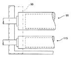
現像装置113は、図2及び図3に示すように、現像剤供給部114、ケース125、第1現像ローラ99、第2現像ローラ115、ドクタブレード116を少なくとも備えている。現像剤供給部114は、収容槽117、攪拌ローラ118、攪拌パドル97を備えている。収容槽117は、感光体ドラム108と長さがほぼ等しい箱状に形成されており、内部に現像剤126を収容する。攪拌パドル97の上方には、ドクタブレード116で掻き落とされた現像剤126が通過するセパレータ120と、セパレータ120を通過した現像剤126を攪拌ローラ118へと搬送する搬送スクリュ121とが配設されている。また、攪拌ローラ118の下方には現像装置113内のトナー濃度を検知するトナー濃度検知センサ119が配設され、各現像ローラ99,115の両端部にはサイドシール96(図4参照)が配設されている。   As shown in FIGS. 2 and 3, the developing device 113 includes at least a developer supply unit 114, a case 125, a first developing roller 99, a second developing roller 115, and a doctor blade 116. The developer supply unit 114 includes a storage tank 117, a stirring roller 118, and a stirring paddle 97. The storage tank 117 is formed in a box shape having a length substantially equal to that of the photosensitive drum 108 and stores the developer 126 therein. Above the stirring paddle 97, a separator 120 through which the developer 126 scraped off by the doctor blade 116 passes and a transport screw 121 that transports the developer 126 that has passed through the separator 120 to the stirring roller 118 are disposed. ing. A toner concentration detection sensor 119 for detecting the toner concentration in the developing device 113 is disposed below the stirring roller 118, and side seals 96 (see FIG. 4) are disposed at both ends of the developing rollers 99 and 115, respectively. It is installed.

現像剤126はトナーと磁性キャリアとを含んだ2成分現像剤であり、現像剤126は攪拌ローラ118の上方に設けられた補給部95から適宜供給される。トナーは乳化重合法または懸濁重合法により製造された球状の微粒子であり、種々の染料または顔料を混入または分散した合成樹脂で構成される塊を粉砕して得られても、粉砕加工等により形成されてもよい。トナーの平均粒径は3μm以上7μm以下であり、磁性キャリアは20μm以上50μm以下である。攪拌ローラ118は各現像ローラ99,115及び感光体ドラム108と平行に配設されており、軸芯周りに回転することでトナーと磁性キャリアとを攪拌すると共に攪拌した現像剤126を搬送する。攪拌パドル97も各現像ローラ99,115及び感光体ドラム108と平行に配設されており、攪拌ローラ118とは逆方向に回転することで攪拌した現像剤126を各現像ローラ99,115に向けて搬送する。   The developer 126 is a two-component developer containing toner and a magnetic carrier, and the developer 126 is appropriately supplied from a replenishing unit 95 provided above the stirring roller 118. The toner is spherical fine particles produced by an emulsion polymerization method or a suspension polymerization method. Even if the toner is obtained by pulverizing a lump composed of a synthetic resin mixed or dispersed with various dyes or pigments, It may be formed. The average particle diameter of the toner is 3 μm or more and 7 μm or less, and the magnetic carrier is 20 μm or more and 50 μm or less. The stirring roller 118 is disposed in parallel with the developing rollers 99 and 115 and the photosensitive drum 108, and rotates around the axis to stir the toner and the magnetic carrier and to transport the stirred developer 126. The stirring paddle 97 is also arranged in parallel with the developing rollers 99 and 115 and the photosensitive drum 108, and the developer 126 stirred by rotating in the opposite direction to the stirring roller 118 is directed toward the developing rollers 99 and 115. Transport.

上述の構成により現像剤供給部114は、補給部95に供給されたトナーまたは現像剤126を磁性キャリアと攪拌しながら攪拌ローラ118によって搬送する。そして現像剤供給部114は、搬送された現像剤126を攪拌パドル97によってさらに攪拌しつつ各現像ローラ99,115に搬送する。   With the above-described configuration, the developer supply unit 114 conveys the toner or developer 126 supplied to the replenishment unit 95 by the stirring roller 118 while stirring the toner or the developer 126 with the magnetic carrier. Then, the developer supply unit 114 transports the transported developer 126 to the developing rollers 99 and 115 while further stirring the developer 126 with the stirring paddle 97.

ケース125は箱状に形成され、収容槽117に取り付けられて収容槽117と共に各現像ローラ99,115等を覆う。また、ケース125の感光体ドラム108と相対する部分には、各現像ローラ99,115を臨ませるための開口部が設けられている。   The case 125 is formed in a box shape, is attached to the storage tank 117, and covers the developing rollers 99, 115 and the like together with the storage tank 117. In addition, an opening for allowing the developing rollers 99 and 115 to face is provided in a portion of the case 125 facing the photosensitive drum 108.

第1現像ローラ99は円柱状に形成され、攪拌パドル97と感光体ドラム108との間であって上述した開口部からその周面の一部を臨ませて配設されている。第1現像ローラ99は感光体ドラム108と平行に設けられ、感光体ドラム108との間に所定の間隔を開けて配設されている。第1現像ローラ99と感光体ドラム108との間の空間は、現像剤126のトナーを感光体ドラム108に吸着させて静電潜像を現像してトナー像を得る現像領域を形成している。第1現像ローラ99の下方には第2現像ローラ115が配設されている。第2現像ローラ115も感光体ドラム108と平行に設けられ、感光体ドラム108との間に所定の間隔を開けて配設されている。   The first developing roller 99 is formed in a columnar shape, and is disposed between the stirring paddle 97 and the photosensitive drum 108 with a part of the peripheral surface facing the opening described above. The first developing roller 99 is provided in parallel with the photosensitive drum 108 and is disposed at a predetermined interval between the first developing roller 99 and the photosensitive drum 108. The space between the first developing roller 99 and the photosensitive drum 108 forms a developing region in which the toner of the developer 126 is attracted to the photosensitive drum 108 to develop the electrostatic latent image and obtain a toner image. . A second developing roller 115 is disposed below the first developing roller 99. The second developing roller 115 is also provided in parallel with the photosensitive drum 108, and is disposed at a predetermined interval between the second developing roller 115 and the photosensitive drum 108.

攪拌パドル97から第1現像ローラ99に供給された現像剤126は、感光体ドラム108とは逆方向に回転する第1現像ローラ99によって感光体ドラム108の外周面上に形成された静電潜像に供給される。そして、第1現像ローラ99から感光体ドラム108に供給されずに第1現像ローラ99の外周面上に残存した現像剤126は、その一部が第2現像ローラ115に受け渡される。感光体ドラム108とは逆方向に回転する第2現像ローラ115は、第1現像ローラ99から供給された現像剤126を感光体ドラム108の外周面上に形成された静電潜像に供給する。このような現像ローラを2本有する構成により、感光体ドラム108の回転速度が速い場合であっても、各現像ローラ99,115の回転速度を早めることなく、感光体ドラム108の外周面上に十分な現像剤126を供給することができる。   The developer 126 supplied from the stirring paddle 97 to the first developing roller 99 is an electrostatic latent image formed on the outer peripheral surface of the photosensitive drum 108 by the first developing roller 99 rotating in the direction opposite to the photosensitive drum 108. Supplied to the image. A part of the developer 126 remaining on the outer peripheral surface of the first developing roller 99 without being supplied from the first developing roller 99 to the photosensitive drum 108 is transferred to the second developing roller 115. The second developing roller 115 rotating in the opposite direction to the photosensitive drum 108 supplies the developer 126 supplied from the first developing roller 99 to the electrostatic latent image formed on the outer peripheral surface of the photosensitive drum 108. . With such a configuration having two developing rollers, even when the rotational speed of the photosensitive drum 108 is high, the rotational speed of the developing rollers 99 and 115 is not increased on the outer peripheral surface of the photosensitive drum 108. Sufficient developer 126 can be supplied.

次に、第1現像ローラ99及び第2現像ローラ115について説明する。両者は、第1現像ローラ99の外径が30mm、第2現像ローラ115の外径が25mmである点を除いて同一の構成であるので、第1現像ローラ99を代表して説明し第2現像ローラ115の説明は省略する。   Next, the first developing roller 99 and the second developing roller 115 will be described. Both have the same configuration except that the outer diameter of the first developing roller 99 is 30 mm and the outer diameter of the second developing roller 115 is 25 mm. Therefore, the first developing roller 99 will be described as a representative. A description of the developing roller 115 is omitted.

第1現像ローラ99は、図4に示すように、芯金134、円筒状のマグネットローラ133、円筒状の現像スリーブ132を備えている。芯金134は感光体ドラム108と平行に配設され、ケース125に回転することなく固定されている。マグネットローラ133は、磁性材料で構成されかつ円筒状に形成されていると共に、図示しない複数の固定磁極が取り付けられている。マグネットローラ133は現像スリーブ132内に収容されており、芯金134に軸芯回りに回転することなく固定されている。   As shown in FIG. 4, the first developing roller 99 includes a core bar 134, a cylindrical magnet roller 133, and a cylindrical developing sleeve 132. The cored bar 134 is disposed in parallel with the photosensitive drum 108 and is fixed to the case 125 without rotating. The magnet roller 133 is made of a magnetic material and formed in a cylindrical shape, and a plurality of fixed magnetic poles (not shown) are attached to the magnet roller 133. The magnet roller 133 is accommodated in the developing sleeve 132 and fixed to the cored bar 134 without rotating around the axis.

複数の固定磁極は長尺で棒状の磁石であり、マグネットローラ133に取り付けられている。各固定磁極はマグネットローラ133の長手方向に沿ってそれぞれ延びており、マグネットローラ133の全長にわたって設けられている。第1現像ローラ99が有する複数の固定磁極のうちの一つは攪拌パドル97と相対して汲み上げ磁極を構成している。この汲み上げ磁極の働きにより、現像スリーブ132すなわち第1現像ローラ99の外表面上に磁気力を生じさせて収容槽117内の現像剤126を現像スリーブ132の外表面に吸着させる。第1現像ローラ99が有する複数の固定磁極のうちの他の一つは感光体ドラム108と相対して現像磁極をなしており、現像スリーブ132の外表面上に磁気力を生じさせて、現像スリーブ132と感光体ドラム108との間に磁界を形成する。この現像磁極の磁界によって磁気ブラシを形成することにより、現像スリーブ132の外表面に吸着された現像剤126のトナーを感光体ドラム108に受け渡すように構成されている。第1現像ローラ99が有する複数の固定磁極のうちのさらに他の一つは、第2現像ローラ115と相対して受け渡し磁極を構成している。この受け渡し磁極の働きにより、第1現像ローラ99から第2現像ローラ115へと現像剤126が受け渡される。   The plurality of fixed magnetic poles are long and rod-like magnets, and are attached to the magnet roller 133. Each fixed magnetic pole extends along the longitudinal direction of the magnet roller 133 and is provided over the entire length of the magnet roller 133. One of the plurality of fixed magnetic poles of the first developing roller 99 constitutes a pumping magnetic pole opposite to the stirring paddle 97. By the action of the pumping magnetic pole, a magnetic force is generated on the outer surface of the developing sleeve 132, that is, the first developing roller 99, and the developer 126 in the storage tank 117 is attracted to the outer surface of the developing sleeve 132. The other one of the plurality of fixed magnetic poles of the first developing roller 99 forms a developing magnetic pole relative to the photosensitive drum 108, and generates a magnetic force on the outer surface of the developing sleeve 132 to develop the developing magnetic pole. A magnetic field is formed between the sleeve 132 and the photosensitive drum 108. By forming a magnetic brush with the magnetic field of the developing magnetic pole, the toner of the developer 126 adsorbed on the outer surface of the developing sleeve 132 is delivered to the photosensitive drum 108. Still another one of the plurality of fixed magnetic poles of the first developing roller 99 constitutes a delivery magnetic pole facing the second developing roller 115. The developer 126 is transferred from the first developing roller 99 to the second developing roller 115 by the function of the transfer magnetic pole.

第2現像ローラ115が有する複数の固定磁極のうちの一つは感光体ドラム108と相対して現像磁極をなしており、現像スリーブ132の外表面に吸着された現像剤126のトナーを感光体ドラム108に受け渡す。第2現像ローラ115が有する複数の固定磁極のうちの他の一つは、第1現像ローラ99と相対して受け取り磁極を構成している。この受け取り磁極の働きにより、第1現像ローラ99からの現像剤126が第2現像ローラ115へと受け渡される。   One of the plurality of fixed magnetic poles of the second developing roller 115 forms a developing magnetic pole opposite to the photosensitive drum 108, and the toner of the developer 126 adsorbed on the outer surface of the developing sleeve 132 is transferred to the photosensitive body. Delivered to the drum 108. The other one of the plurality of fixed magnetic poles of the second developing roller 115 constitutes a receiving magnetic pole opposite to the first developing roller 99. The developer 126 from the first developing roller 99 is delivered to the second developing roller 115 by the function of the receiving magnetic pole.

上述した固定磁極は、現像スリーブ132の外表面に現像剤126を吸着させると、固定磁極が生じる磁力線に沿って現像剤126の磁性キャリアを複数重ねさせ、現像スリーブ132の外表面上に磁性キャリアを穂立ちさせる。すると、この穂立ちした磁性キャリアにトナーが吸着する。すなわち現像スリーブ132は、マグネットローラ133の磁力によりその外表面に現像剤126を吸着する。   When the developer 126 is adsorbed on the outer surface of the developing sleeve 132, the fixed magnetic pole described above causes a plurality of magnetic carriers of the developer 126 to overlap with each other along the lines of magnetic force generated by the fixed magnetic pole, and the magnetic carrier on the outer surface of the developing sleeve 132. Sprouting. As a result, the toner is adsorbed to the magnetic carrier that has grown up. That is, the developing sleeve 132 attracts the developer 126 to the outer surface by the magnetic force of the magnet roller 133.

現像スリーブ132は、図4に示すように、円筒状に形成されている。現像スリーブ132は、マグネットローラ133を内包して、芯金134を中心として回転自在に設けられている。現像スリーブ132の端部にはギヤ94aを有するフランジ94が形成されており、駆動ギヤ93からの回転駆動力により現像スリーブ132は、その内周面が固定磁極に対して順に相対するように回転される。現像スリーブ132は、アルミニウム合金、真鍮、ステンレス鋼(SUS)、導電性の樹脂等の非磁性材料で構成されており、図9(a)に示す表面処理装置1によってその外表面に粗面化処理が施されている。   As shown in FIG. 4, the developing sleeve 132 is formed in a cylindrical shape. The developing sleeve 132 includes a magnet roller 133 and is provided to be rotatable about a cored bar 134. A flange 94 having a gear 94a is formed at the end of the developing sleeve 132, and the developing sleeve 132 is rotated by the rotational driving force from the driving gear 93 so that the inner peripheral surface thereof is sequentially opposed to the fixed magnetic pole. Is done. The developing sleeve 132 is made of a nonmagnetic material such as aluminum alloy, brass, stainless steel (SUS), or conductive resin, and is roughened on the outer surface by the surface treatment apparatus 1 shown in FIG. Processing has been applied.

アルミニウム合金は、加工性、軽さの面で優れている。アルミニウム合金を用いる場合には、A6063、A5056及びA3003を用いることが好ましい。ステンレスを用いる場合には、SUS303、SUS304及びSUS316を用いるのが好ましい。なお図示例では、現像スリーブ132はアルミニウム合金で構成されている。   Aluminum alloys are excellent in terms of workability and lightness. When an aluminum alloy is used, it is preferable to use A6063, A5056, and A3003. When using stainless steel, it is preferable to use SUS303, SUS304, and SUS316. In the illustrated example, the developing sleeve 132 is made of an aluminum alloy.

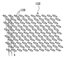
また、現像スリーブ132の外表面には、図5、図6、図7(a)及び図8に示すように、平面視が楕円形状の凹み139が多数設けられている。この凹み139は、軸心周りに回転される先端部において周方向に間隔を開けて切削刃が設けられた回転工具により切削加工されて形成される。そして、回転工具の軸心と交差する状態に配置された現像スリーブがその軸心周りに回転されながら、回転工具と現像スリーブとがこの現像スリーブの長手方向に相対的に移動されることにより形成されたものである。この加工をDA加工と呼び、DA加工により形成された現像スリーブをDAスリーブと呼ぶ。   Further, as shown in FIGS. 5, 6, 7 (a), and 8, the outer surface of the developing sleeve 132 is provided with a number of recesses 139 that are elliptical in plan view. The dent 139 is formed by cutting with a rotary tool provided with a cutting blade at an interval in the circumferential direction at the tip portion rotated about the axis. Then, the developing sleeve arranged so as to intersect with the axis of the rotating tool is rotated around the axis while the rotating tool and the developing sleeve are relatively moved in the longitudinal direction of the developing sleeve. It has been done. This processing is called DA processing, and the developing sleeve formed by DA processing is called DA sleeve.

凹み139は現像スリーブ132の外表面上に窪みとなるように形成され、互いに重ならないように規則的に多数(複数)配置されている。なお、本発明では、現像スリーブ132の周方向及び長手方向において互いに隣り合う凹み139間の間隔が一定となるように配置されていることを、凹み139が規則的に配置されているという。すなわち、現像スリーブ132の周方向及び長手方向において互いに隣り合う凹み139間の間隔は一定となっている。また本発明では、現像スリーブ132の周方向及び長手方向において互いに隣り合う凹み139間の間隔が一定でないことを、凹み139が不規則的に配置されているという。   The depressions 139 are formed on the outer surface of the developing sleeve 132 so as to form depressions, and are regularly (multiple) arranged so as not to overlap each other. In the present invention, the fact that the intervals between the recesses 139 adjacent to each other in the circumferential direction and the longitudinal direction of the developing sleeve 132 are constant is referred to as the regular arrangement of the recesses 139. That is, the interval between the recesses 139 adjacent to each other in the circumferential direction and the longitudinal direction of the developing sleeve 132 is constant. Further, in the present invention, the interval between the recesses 139 adjacent to each other in the circumferential direction and the longitudinal direction of the developing sleeve 132 is not constant, and the recesses 139 are irregularly arranged.

規則的に配置されている例として、例えば図5に示すように、凹み139が1列の螺旋状で周方向に同ピッチ(同間隔)で配置されている場合が挙げられる。同様に、図23に示すように、凹み139が2列の螺旋状で1列目と2列目とがそれぞれ円周方向に同ピッチかつ長手方向に整列して配置されている場合が挙げられる。さらに、図24に示すように、凹み139が2列の螺旋状で1列目と2列目とがそれぞれ円周方向に同ピッチかつ各列が長手方向に整列しないように円周方向にずれて配置されている場合等が挙げられる。また、凹み139の配置が3列またはそれ以上の螺旋状の場合も同様である。   As an example of regular arrangement, for example, as shown in FIG. 5, there is a case where the recesses 139 are arranged in a row of spirals and arranged in the circumferential direction at the same pitch (same interval). Similarly, as shown in FIG. 23, there may be mentioned a case where the recesses 139 are formed in two rows of spirals, and the first row and the second row are arranged in the circumferential direction at the same pitch and in the longitudinal direction. . Further, as shown in FIG. 24, the recesses 139 are spirally formed in two rows, and the first row and the second row are shifted in the circumferential direction so that each row has the same pitch in the circumferential direction and each row is not aligned in the longitudinal direction. The case where it is arranged is mentioned. The same applies to the case where the recesses 139 are arranged in three rows or more.

不規則的に配置されている例として、例えば図20及び図21に示すように、凹み139の間隔が所定の方向(例えば、現像スリーブ132の長手方向中央部から両端部への方向)に向かって徐々に狭くなるように配置されている場合が挙げられる。また、図25に示すように、凹み139が2列の螺旋状であり1列目と2列目との円周方向のピッチがそれぞれ異なり、かつ各列が長手方向に整列して配置されている場合が挙げられる。さらに、図26に示すように、凹み139が2列の螺旋状であり1列目と2列目との円周方向のピッチがそれぞれ異なり、かつ各列が長手方向に整列しないように円周方向にずれて配置されている場合等が挙げられる。また、凹み139の配置が3列またはそれ以上の螺旋状の場合も同様である。   As an example of irregular arrangement, for example, as shown in FIGS. 20 and 21, the interval between the recesses 139 is directed in a predetermined direction (for example, the direction from the center in the longitudinal direction of the developing sleeve 132 to both ends). The case where it arrange | positions so that it may become narrow gradually is mentioned. In addition, as shown in FIG. 25, the recesses 139 have two rows of spirals, the pitches in the circumferential direction of the first row and the second row are different from each other, and the rows are arranged in the longitudinal direction. There are cases. Furthermore, as shown in FIG. 26, the recesses 139 are formed in two rows of spirals, the circumferential pitches of the first row and the second row are different from each other, and the circumferences are arranged so that the rows are not aligned in the longitudinal direction. The case where it has shifted | deviated to a direction, etc. are mentioned. The same applies to the case where the recesses 139 are arranged in three rows or more.

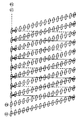
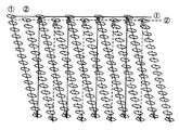
図22は各現像ローラ99,115の配置を感光体ドラム108側から見た概略図であり、図22における矢印方向に第1現像ローラ99の現像スリーブ132を擬似的に透過して第2現像ローラ115の現像スリーブ132を投影したものが図27である。図27において、第1現像ローラ99に形成された凹み139を黒塗りで、第2現像ローラ115に形成された凹み139を白抜きでそれぞれ表している。各現像ローラ99,115それぞれの凹み139共に、図27に一点鎖線で示す各現像スリーブ132の軸線に対して、その軸線方向の端部同士を結んだ線(半月形の直径を含む)が若干傾斜するように形成されている。そして、各現像ローラ99,135の凹み139はその傾斜方向が互いに同じ向き、すなわち現像スリーブ132の軸線を介して対象形となるようにそれぞれ形成されている。これにより、各現像ローラ99,115に形成された凹み139は、各現像ローラ99,115の近接対向部において凹み139の傾斜方向が互いに逆向きとなるようにそれぞれ形成されている。   FIG. 22 is a schematic view of the arrangement of the developing rollers 99 and 115 as viewed from the photosensitive drum 108 side. The second developing is performed by passing through the developing sleeve 132 of the first developing roller 99 in the direction of the arrow in FIG. FIG. 27 is a projection of the developing sleeve 132 of the roller 115. In FIG. 27, the dent 139 formed in the first developing roller 99 is shown in black, and the dent 139 formed in the second developing roller 115 is shown in white. In each of the recesses 139 of the developing rollers 99 and 115, a line (including a half-moon diameter) connecting the end portions in the axial direction with respect to the axial line of the developing sleeve 132 shown by a one-dot chain line in FIG. It is formed to be inclined. The recesses 139 of the developing rollers 99 and 135 are formed so that the inclination directions thereof are the same as each other, that is, the object shape is formed via the axis of the developing sleeve 132. As a result, the recesses 139 formed in the developing rollers 99 and 115 are formed so that the inclination directions of the recesses 139 are opposite to each other at the proximity facing portions of the developing rollers 99 and 115, respectively.

さらに凹み139は、図6、図7(a)及び図8に示すように、現像スリーブ132の長手方向に沿って複数並べられて配置されていると共に、周方向において互いに隣り合うもの同士は凹み139の長さの約半分程度位置がずれるように配置されている。さらに凹み139は、図9(a)に示す表面処理装置1により現像スリーブ132の外表面に形成されるため、現像スリーブ132の外表面上に図6中の一点鎖線で示す螺旋上に並べられて配置されている。   Further, as shown in FIGS. 6, 7A and 8, a plurality of the recesses 139 are arranged along the longitudinal direction of the developing sleeve 132, and those adjacent to each other in the circumferential direction are recessed. It is arranged so that the position is shifted by about half of the length of 139. Furthermore, since the recesses 139 are formed on the outer surface of the developing sleeve 132 by the surface treatment apparatus 1 shown in FIG. 9A, they are arranged on the outer surface of the developing sleeve 132 on a spiral indicated by a one-dot chain line in FIG. Are arranged.

また凹み139は、図7(b)に示すように、その幅方向(現像スリーブ132の周方向)の断面形状がV字形状に形成され、図7(c)に示すように、その長手方向(現像スリーブ132の長手方向)の断面形状が円弧状の曲面となるように形成されている。さらに凹み139は、図9(a)に示す表面処理装置1により現像スリーブ132の外表面に形成されるため、図8に示すように、その長手方向が若干弓状に湾曲している。なお本発明では、その長さが幅よりも長く外縁が曲線で形成されていれば、その長手方向において直線形状であっても若干湾曲していても、総称して楕円形状とする。   The recess 139 has a V-shaped cross-section in the width direction (the circumferential direction of the developing sleeve 132) as shown in FIG. 7B, and its longitudinal direction as shown in FIG. 7C. The cross-sectional shape (longitudinal direction of the developing sleeve 132) is an arcuate curved surface. Further, since the recess 139 is formed on the outer surface of the developing sleeve 132 by the surface treatment apparatus 1 shown in FIG. 9A, the longitudinal direction thereof is slightly curved in an arcuate shape as shown in FIG. In the present invention, as long as the length is longer than the width and the outer edge is formed in a curve, the shape is generally an elliptical shape regardless of whether it is linear or slightly curved in the longitudinal direction.

さらに凹み139は、その長手方向の長さ(長径)が1.0mm以上2.3mm以下であり、幅方向の幅(短径)は0.3mm以上0.7mm以下であると共に、その深さは0.05mm以上0.15mm以下である。さらに凹み139は、現像スリーブ132の外表面100mm当たりに50〜250個程度設けられている。すなわち複数の凹み139は、その総容量が現像スリーブ132の外表面100mm当たり0.5mm以上7.0mm以下となるように形成されている。さらに凹み139は、現像スリーブ132と共に回転する感光体ドラム108の周方向に1mm当たり1.0個以上3.0個以下設けられている。なお、図6、図7(a)及び図8では、図中の左右方向が現像スリーブ132の長手方向である。 Furthermore, the length (major axis) in the longitudinal direction of the recess 139 is 1.0 mm or more and 2.3 mm or less, and the width (minor axis) in the width direction is 0.3 mm or more and 0.7 mm or less, and its depth. Is 0.05 mm or more and 0.15 mm or less. Further, about 50 to 250 recesses 139 are provided per 100 mm 2 of the outer surface of the developing sleeve 132. That is, the plurality of recesses 139 are formed so that the total capacity is 0.5 mm 3 or more and 7.0 mm 3 or less per 100 mm 2 of the outer surface of the developing sleeve 132. Further, 1.0 to 3.0 recesses 139 are provided per mm in the circumferential direction of the photosensitive drum 108 that rotates together with the developing sleeve 132. 6, 7 </ b> A, and 8, the horizontal direction in the drawing is the longitudinal direction of the developing sleeve 132.

一般に凹み139が深いほど現像剤126の搬送性能は向上するが、溝を外表面に設けた従来の現像スリーブと同様に周期的なピッチムラが発生し易くなる。一方、凹み139が浅いほどピッチムラは発生しにくくなるが、現像剤126の搬送性能が低下する。特に近年では、小粒径のトナーや磁性キャリアを用いた画像形成技術の進歩及び近接現像の画像形成技術の進歩等により画像再現性が向上しているため、ピッチムラが発生し易くなっている。そこで、上述した現像スリーブ132では凹み139の深さを浅めに設定し、凹み139の分布密度を増やすことにより現像剤搬送性能の向上とピッチムラ発生防止との両立を図っている。   In general, the deeper the recess 139, the better the developer 126 conveyance performance, but periodic pitch unevenness is likely to occur as in the case of a conventional developing sleeve having grooves on the outer surface. On the other hand, as the dent 139 is shallower, pitch unevenness is less likely to occur, but the transport performance of the developer 126 is degraded. In particular, in recent years, the image reproducibility has been improved due to the progress of image forming technology using a toner having a small particle diameter or a magnetic carrier and the image forming technology of proximity development, and therefore, pitch unevenness is likely to occur. Therefore, in the developing sleeve 132 described above, the depth of the recesses 139 is set to be shallow, and the distribution density of the recesses 139 is increased to achieve both improvement in developer conveying performance and prevention of pitch unevenness.

ドクタブレード116は、現像装置113の感光体ドラム108寄りの端部近傍に設けられている。ドクタブレード116は、第1現像ローラ99の現像スリーブ132の外表面と所定の間隔を開けた状態でケース125に取り付けられている。ドクタブレード116は、所望の厚さを越える現像スリーブ132上の現像剤126を収容槽117内に削ぎ落として、現像領域に搬送される現像スリーブ132上の現像剤126を所望の厚さに形成する。   The doctor blade 116 is provided near the end of the developing device 113 near the photosensitive drum 108. The doctor blade 116 is attached to the case 125 with a predetermined distance from the outer surface of the developing sleeve 132 of the first developing roller 99. The doctor blade 116 scrapes off the developer 126 on the developing sleeve 132 exceeding a desired thickness into the storage tank 117, and forms the developer 126 on the developing sleeve 132 to be conveyed to the developing region to a desired thickness. To do.

上述した現像装置113は、現像剤供給部114でトナーと磁性キャリアとを十分に攪拌し、攪拌した現像剤126を固定磁極により現像スリーブ132の外表面に吸着する。そして、現像スリーブ132の回転により複数の固定磁極からの磁力によって吸着した現像剤126を現像領域に向けて搬送し、ドクタブレード116で所望の厚さに形成された現像剤126を感光体ドラム108に吸着させる。このように現像装置113は、現像剤126を現像ローラ99,115にそれぞれ担持して現像領域に搬送し、感光体ドラム108上の静電潜像を顕像化してトナー像を形成する。   In the developing device 113 described above, the toner and the magnetic carrier are sufficiently stirred by the developer supply unit 114, and the stirred developer 126 is attracted to the outer surface of the developing sleeve 132 by the fixed magnetic pole. Then, the developer 126 adsorbed by the magnetic force from the plurality of fixed magnetic poles by the rotation of the developing sleeve 132 is conveyed toward the developing region, and the developer 126 formed to a desired thickness by the doctor blade 116 is transferred to the photosensitive drum 108. Adsorb to. As described above, the developing device 113 carries the developer 126 on the developing rollers 99 and 115 and conveys the developer 126 to the developing region, and visualizes the electrostatic latent image on the photosensitive drum 108 to form a toner image.

そして現像装置113は、現像済みの現像剤126を収容槽117に向けて離脱させる。そして収容槽117内に収容された現像済みの現像剤126は、再度他の現像剤126と十分に攪拌されて感光体ドラム108の現像に用いられる。なお現像装置113は、現像剤供給部114におけるトナー濃度が低下したことをトナー濃度検知センサ119が検知すると、補給部95からトナー及び現像剤を攪拌ローラ118に向けて送り出す。   Then, the developing device 113 causes the developed developer 126 to be released toward the storage tank 117. The developed developer 126 stored in the storage tank 117 is sufficiently stirred again with another developer 126 and used for developing the photosensitive drum 108. When the toner concentration detection sensor 119 detects that the toner concentration in the developer supplying unit 114 has decreased, the developing device 113 sends the toner and developer from the replenishing unit 95 toward the stirring roller 118.

上述の画像形成装置101は、以下に示すように記録紙107上に画像を形成する。先ず画像形成装置101は、感光体ドラム108を回転してその外表面を一様に帯電ローラ109により−700Vに帯電する。次に、感光体ドラム108の外表面にレーザ光を照射して表面を露光し、画像部分を−150Vに減衰させて感光体ドラム108の外表面に静電潜像を形成する。そして静電潜像が現像領域に到達すると、この静電潜像に−550Vの現像バイアス電圧を印加して現像装置113の各現像スリーブ132の外表面に吸着した現像剤126が感光体ドラム108の外表面に吸着する。これにより感光体ドラム108上の静電潜像が現像され、感光体ドラム108の外表面上にトナー像が形成される。   The image forming apparatus 101 described above forms an image on the recording paper 107 as described below. First, the image forming apparatus 101 rotates the photosensitive drum 108 and uniformly charges the outer surface thereof to −700 V by the charging roller 109. Next, the outer surface of the photosensitive drum 108 is irradiated with laser light to expose the surface, and the image portion is attenuated to −150 V to form an electrostatic latent image on the outer surface of the photosensitive drum 108. When the electrostatic latent image reaches the developing area, a developing bias voltage of −550 V is applied to the electrostatic latent image, and the developer 126 adsorbed on the outer surface of each developing sleeve 132 of the developing device 113 is transferred to the photosensitive drum 108. Adsorb to the outer surface of the. As a result, the electrostatic latent image on the photosensitive drum 108 is developed, and a toner image is formed on the outer surface of the photosensitive drum 108.

一方、給紙ローラ124等により給送された記録紙107が各プロセスカートリッジ106の感光体ドラム108と転写ユニット104の搬送ベルト129との間に送り込まれ、感光体ドラム108の外表面上に形成されたトナー像が記録紙107に転写される。転写されたトナー像は、記録紙107が定着ユニット105に送られることにより記録紙107上に定着される。この一連の動作により、画像形成装置101は記録紙107上にフルカラー画像を形成する。また、転写されずに感光体ドラム108上に残ったトナーは、クリーニング装置112によって回収される。残留トナーを除去された感光体ドラム108は除電装置98でその表面電位を初期化され、次回の画像形成プロセスに供される。   On the other hand, the recording paper 107 fed by the paper feed roller 124 or the like is fed between the photosensitive drum 108 of each process cartridge 106 and the conveying belt 129 of the transfer unit 104 and formed on the outer surface of the photosensitive drum 108. The toner image thus transferred is transferred to the recording paper 107. The transferred toner image is fixed on the recording paper 107 when the recording paper 107 is sent to the fixing unit 105. Through this series of operations, the image forming apparatus 101 forms a full-color image on the recording paper 107. Further, the toner remaining on the photosensitive drum 108 without being transferred is collected by the cleaning device 112. The surface potential of the photosensitive drum 108 from which the residual toner has been removed is initialized by the static eliminator 98 and used for the next image forming process.

画像形成装置101では、環境変動や経時変動による画質の変動を抑えるためにプロセスコントロールを実施している。具体的には、まず現像装置113における現像能力を検出する。これは、例えば現像バイアス電圧を一定にした条件下であるトナーパターンの画像を感光体ドラム108上に形成し、その画像濃度を図示しない光センサで検出して濃度変化から現像能力を把握する。そして、この現像能力が所定の目標現像能力となるようにトナー濃度の目標値を変更することで、画質を一定に保つことができる。例えば、光センサで検出したトナーパターンの画像濃度が目標現像濃度よりも低い場合には、トナー濃度を高くするように図示しない制御手段としてのCPUが攪拌パドル97及び攪拌ローラ118の動作を制御する。一方、光センサで検出したトナーパターンの画像濃度が目標現像濃度よりも高い場合には、トナー濃度を低くするようにCPUが攪拌パドル97及び攪拌ローラ118の動作を制御する。ここで、トナー濃度はトナー濃度検知センサ119で検知される。なお、感光体ドラム108上に形成されるトナーパターンの画像濃度は、現像スリーブ132による画像濃度周期ムラの影響で多少変動することがある。   In the image forming apparatus 101, process control is performed in order to suppress fluctuations in image quality due to environmental fluctuations and temporal fluctuations. Specifically, first, the developing ability in the developing device 113 is detected. For example, an image of a toner pattern under a condition in which the development bias voltage is constant is formed on the photosensitive drum 108, and the image density is detected by an optical sensor (not shown) to grasp the developing ability from the density change. The image quality can be kept constant by changing the target value of the toner density so that the developing ability becomes a predetermined target developing ability. For example, when the image density of the toner pattern detected by the optical sensor is lower than the target development density, the CPU as control means (not shown) controls the operations of the stirring paddle 97 and the stirring roller 118 so as to increase the toner density. . On the other hand, when the image density of the toner pattern detected by the optical sensor is higher than the target development density, the CPU controls the operations of the stirring paddle 97 and the stirring roller 118 so as to lower the toner density. Here, the toner density is detected by the toner density detection sensor 119. It should be noted that the image density of the toner pattern formed on the photosensitive drum 108 may vary somewhat due to the influence of the image density cycle unevenness caused by the developing sleeve 132.

各現像スリーブ132は、図9(a)に示す表面処理装置1によってその外表面に凹み139がそれぞれ形成される。表面処理装置1は、図9(a)に示すように、ベース3と、保持部4と、回転駆動部としてのモータ2と、移動手段としての工具移動部5と、工具6と、制御手段としての図示しない制御装置とを備えている。平板状に形成されたベース3は工場のフロアやテーブル上等に設置され、その上面は水平方向と平行に保たれている。ベース3は、その平面形状が矩形状となるように形成されている。   Each developing sleeve 132 has a recess 139 formed on the outer surface thereof by the surface treatment apparatus 1 shown in FIG. As shown in FIG. 9A, the surface treatment apparatus 1 includes a base 3, a holding unit 4, a motor 2 as a rotation driving unit, a tool moving unit 5 as a moving unit, a tool 6, and a control unit. And a control device (not shown). The base 3 formed in a flat plate shape is installed on a factory floor, a table, or the like, and its upper surface is kept parallel to the horizontal direction. The base 3 is formed so that its planar shape is rectangular.

保持部4は、固定保持部7とスライド保持部8とを備えている。固定保持部7は、ベース3の長手方向の一端部から立設した固定柱9と、固定柱9の上端部に設けられた回転チャック10とを備えている。厚手の円板状に形成された回転チャック10は、固定柱9の上端部に回転自在に支持されている。回転チャック10の回転中心はベース3の上面と平行に配置されており、そこには円柱状のチャックピン11が立設している。チャックピン11は回転チャック10の回転中心軸と同軸上に配置されている。   The holding unit 4 includes a fixed holding unit 7 and a slide holding unit 8. The fixed holding unit 7 includes a fixed column 9 erected from one end of the base 3 in the longitudinal direction, and a rotating chuck 10 provided at the upper end of the fixed column 9. The rotating chuck 10 formed in a thick disc shape is rotatably supported on the upper end portion of the fixed column 9. The rotation center of the rotary chuck 10 is arranged in parallel with the upper surface of the base 3, and a cylindrical chuck pin 11 is erected there. The chuck pin 11 is disposed coaxially with the rotation center axis of the rotary chuck 10.

スライド保持部8は、スライダ12、スライド柱13、スライド柱13の上端部に設けられたモータ2、モータ2の一端側に設けられた回転チャック14を備えている。スライダ12は、ベース3の表面すなわち回転チャック10及びチャックピン11の軸芯に沿ってスライド自在に設けられている。またスライダ12は、回転チャック10及びチャックピン11の軸芯方向の位置が適宜固定される構成となっている。   The slide holding unit 8 includes a slider 12, a slide column 13, a motor 2 provided at the upper end of the slide column 13, and a rotary chuck 14 provided at one end side of the motor 2. The slider 12 is provided so as to be slidable along the surface of the base 3, that is, along the axis of the rotary chuck 10 and the chuck pin 11. The slider 12 has a configuration in which the positions of the rotary chuck 10 and the chuck pin 11 in the axial direction are appropriately fixed.

スライド柱13はスライダ12上に立設している。回転チャック14は厚手の円板状に形成され、スライド柱13の上端部に取り付けられたモータ2の出力軸に取り付けられている。回転チャック14の回転中心は、回転チャック10及びチャックピン11と同軸となるように構成されている。回転チャック14の中心部には、円柱状のチャックピン15が立設している。チャックピン15は回転チャック14の回転中心軸と同軸上に配置されている。   The slide column 13 is erected on the slider 12. The rotary chuck 14 is formed in a thick disk shape, and is attached to the output shaft of the motor 2 attached to the upper end portion of the slide column 13. The rotation center of the rotary chuck 14 is configured to be coaxial with the rotary chuck 10 and the chuck pin 11. A cylindrical chuck pin 15 is erected at the center of the rotary chuck 14. The chuck pin 15 is arranged coaxially with the rotation center axis of the rotary chuck 14.

上述の構成において、スライド保持部8が固定保持部7から離れた状態で各チャックピン11,15間に凹み139が形成される前の現像スリーブ132が挿入され、その後スライド保持部8が固定保持部7に近付けられる。そして、各チャックピン11,15の先端が現像スリーブ132の端部内にそれぞれ進入して、各チャックピン11,15間に現像スリーブ132を挟んだ状態でスライダ12が固定される。これにより保持部4は、各チャックピン11,15間に現像スリーブ132を挟んだ状態で現像スリーブ132を回転自在に保持する。   In the configuration described above, the developing sleeve 132 before the recess 139 is formed is inserted between the chuck pins 11 and 15 in a state where the slide holding portion 8 is separated from the fixed holding portion 7, and then the slide holding portion 8 is fixedly held. Part 7 is approached. Then, the tip of each chuck pin 11, 15 enters the end of the developing sleeve 132, and the slider 12 is fixed with the developing sleeve 132 sandwiched between the chuck pins 11, 15. Accordingly, the holding unit 4 rotatably holds the developing sleeve 132 with the developing sleeve 132 sandwiched between the chuck pins 11 and 15.

モータ2はスライド柱13の上端部に取り付けられており、回転チャック14をその中心軸線周りに回転駆動する。モータ2は、回転チャック14を回転駆動することで各チャックピン11,15間に挟持された現像スリーブ132を回転させる。   The motor 2 is attached to the upper end of the slide column 13 and rotates the rotary chuck 14 around its central axis. The motor 2 rotates the developing chuck 132 held between the chuck pins 11 and 15 by rotating the rotary chuck 14.

工具移動部5は、リニアガイド16と図示しない移動用アクチュエータとを備えている。リニアガイド16は、レール17とスライダ18とを有しており、レール17はベース3上に設置されている。レール17は直線状に形成されていると共に、その長手方向がベース3の長手方向、各チャックピン11,15の軸心、各チャックピン11,15間に挟持された現像スリーブ132の軸芯とそれぞれ平行となるように配置されている。スライダ18は、レール17にその長手方向に沿って移動自在に支持されている。図示しない移動用アクチュエータは、ベース3に取り付けられていると共に、スライダ18をレール17の長手方向にスライド移動させる。   The tool moving unit 5 includes a linear guide 16 and a moving actuator (not shown). The linear guide 16 has a rail 17 and a slider 18, and the rail 17 is installed on the base 3. The rail 17 is formed in a straight line, and its longitudinal direction is the longitudinal direction of the base 3, the axis of each chuck pin 11, 15, and the axis of the developing sleeve 132 sandwiched between each chuck pin 11, 15. They are arranged so as to be parallel to each other. The slider 18 is supported by the rail 17 so as to be movable along its longitudinal direction. A moving actuator (not shown) is attached to the base 3 and slides the slider 18 in the longitudinal direction of the rail 17.

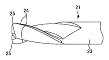
工具6は、工具本体19、工具回転部としての工具回転用モータ20、回転工具としてのエンドミル21を備えている。工具本体19はスライダ18から立設した柱状に形成されている。工具回転用モータ20は、工具本体19の上端部に取り付けられている。工具回転用モータ20は、図9(b)に示すように、その出力軸22が工具本体19の上端部から各チャックピン11,15間に挟持された現像スリーブ132に向かって突出した状態となるように配置されている。出力軸22は、その軸芯がベース3の表面と平行かつ各チャックピン11,15間に挟持された現像スリーブ132の軸芯と交差(図示例では直交)するように配置されている。   The tool 6 includes a tool body 19, a tool rotating motor 20 as a tool rotating unit, and an end mill 21 as a rotating tool. The tool body 19 is formed in a columnar shape standing from the slider 18. The tool rotation motor 20 is attached to the upper end of the tool body 19. As shown in FIG. 9B, the tool rotation motor 20 has an output shaft 22 protruding from the upper end of the tool body 19 toward the developing sleeve 132 sandwiched between the chuck pins 11 and 15. It is arranged to be. The output shaft 22 is arranged so that its axis is parallel to the surface of the base 3 and intersects with the axis of the developing sleeve 132 sandwiched between the chuck pins 11 and 15 (orthogonal in the illustrated example).

エンドミル21は、全体として円柱状に形成され、出力軸22の先端部に取り付けられている。これによりエンドミル21は、その軸芯がベース3の表面と平行かつ各チャックピン11,15間に挟持された現像スリーブ132の軸芯と交差(図示例では直交)するように配置されている。またエンドミル21は、工具本体19の上端部から各チャックピン11,15間に挟持された現像スリーブ132に向かって突出するように配置されている。   The end mill 21 is formed in a cylindrical shape as a whole, and is attached to the distal end portion of the output shaft 22. As a result, the end mill 21 is arranged so that the axis of the end mill 21 is parallel to the surface of the base 3 and intersects the axis of the developing sleeve 132 sandwiched between the chuck pins 11 and 15 (orthogonal in the illustrated example). The end mill 21 is disposed so as to protrude from the upper end of the tool body 19 toward the developing sleeve 132 sandwiched between the chuck pins 11 and 15.

エンドミル21は、図9(c)に示すように、円柱状の本体部23と二つの切削刃24とを備えている。本体部23は工具本体19に取り付けられ、切削刃24は本体部23の現像スリーブ132寄りの先端部に、周方向に間隔を開けて設けられている。切削刃24は、図9(d)に示すように、本体部23の先端部の外縁よりもエンドミル21の外周方向に突出して設けられており、螺旋状に延在して形成されている。また本実施形態では、エンドミル21の切削刃24の先端の外縁25の断面は、図9(c)に示すように、鋭角をなすように形成されている。上述した工具6は、工具回転用モータ20がエンドミル21をその軸芯回りに回転することで、現像スリーブ132の外表面に凹み139を形成する。   The end mill 21 includes a cylindrical main body 23 and two cutting blades 24 as shown in FIG. The main body portion 23 is attached to the tool main body 19, and the cutting blade 24 is provided at a distal end portion of the main body portion 23 near the developing sleeve 132 with an interval in the circumferential direction. As shown in FIG. 9 (d), the cutting blade 24 is provided so as to protrude in the outer peripheral direction of the end mill 21 from the outer edge of the front end portion of the main body portion 23, and is formed to extend in a spiral shape. Moreover, in this embodiment, the cross section of the outer edge 25 of the front-end | tip of the cutting blade 24 of the end mill 21 is formed so that an acute angle may be made, as shown in FIG.9 (c). The tool 6 described above forms a recess 139 on the outer surface of the developing sleeve 132 by the tool rotating motor 20 rotating the end mill 21 around its axis.

制御装置は、周知のRAM、ROM、CPU等を備えたコンピュータである。制御装置は、モータ2と、工具移動部5の移動用アクチュエータと、工具6の工具回転用モータ20等と接続しており、これらの動作を制御して表面処理装置1全体の制御を行う。制御装置は、現像スリーブ132の外表面に凹み139を多数形成する際には、モータ2で現像スリーブ132をその軸芯回りに回転させ、工具回転用モータ20でエンドミル21を回転させる。そして制御装置は、移動用アクチュエータにより工具6を現像スリーブ132の長手方向に移動させる。これにより、切削刃24がエンドミル21の回転に伴い断続的に現像スリーブ132の外表面に切削加工を施し、現像スリーブ132の外表面上に凹み139が多数形成される。   The control device is a computer including a known RAM, ROM, CPU, and the like. The control device is connected to the motor 2, the moving actuator of the tool moving unit 5, the tool rotating motor 20 of the tool 6, and the like, and controls these operations to control the entire surface treatment device 1. When forming a large number of recesses 139 on the outer surface of the developing sleeve 132, the control device rotates the developing sleeve 132 around its axis by the motor 2 and rotates the end mill 21 by the tool rotating motor 20. Then, the control device moves the tool 6 in the longitudinal direction of the developing sleeve 132 by the moving actuator. As a result, the cutting blade 24 intermittently cuts the outer surface of the developing sleeve 132 as the end mill 21 rotates, and a large number of recesses 139 are formed on the outer surface of the developing sleeve 132.

このとき、外縁25の曲率半径により現像スリーブ132の長手方向における凹み139の円弧の曲率半径が、切削刃24の切り込み量により凹み139の深さがそれぞれ定まる。また、工具6の移動速度により現像スリーブ132の長手方向における凹み139の間隔が定まる。ここで、現像スリーブ132外表面の周方向に設ける凹み139の数をn、モータ2の回転数すなわち現像スリーブ132の回転数をN1、エンドミル21の切削刃24の数をm、エンドミル21の回転数をN2とする。そして制御装置は、下式を満たすように、モータ2、工具移動部5の移動用アクチュエータ、工具回転用モータ20の動作をそれぞれ制御する。   At this time, the radius of curvature of the arc of the recess 139 in the longitudinal direction of the developing sleeve 132 is determined by the radius of curvature of the outer edge 25, and the depth of the recess 139 is determined by the cutting amount of the cutting blade 24. Further, the distance between the recesses 139 in the longitudinal direction of the developing sleeve 132 is determined by the moving speed of the tool 6. Here, the number of recesses 139 provided in the circumferential direction of the outer surface of the developing sleeve 132 is n, the number of rotations of the motor 2, that is, the number of rotations of the developing sleeve 132, the number of cutting blades 24 of the end mill 21 is m, and the rotation of the end mill 21. Let the number be N2. Then, the control device controls the operation of the motor 2, the moving actuator of the tool moving unit 5, and the tool rotating motor 20 so as to satisfy the following expression.

N2=N1×〔m/[(n/2)−0.5]〕・・・式1
制御装置は、これらの各要件を適宜変更することで、凹み139の大きさや密度を任意に変更して現像スリーブ132の外表面を加工することができる。さらに制御装置には、キーボード等の各種入力装置やディスプレイ等の各種表示装置が接続されている。
N2 = N1 × [m / [(n / 2) −0.5]] Equation 1
The control device can process the outer surface of the developing sleeve 132 by arbitrarily changing the size and density of the recesses 139 by appropriately changing these requirements. Further, various input devices such as a keyboard and various display devices such as a display are connected to the control device.

次に、表面処理装置1を用いて現像スリーブ132の外表面に切削加工を施し、現像スリーブ132を製造する工程を以下に説明する。先ず、制御装置に入力装置から現像スリーブ132の品番等を入力する。そして、制御装置がエンドミル21を加工開始位置、すなわち現像スリーブ132の一方の端部に位置させた後、凹み139が形成される前の現像スリーブ132を保持部4に保持する。このとき、現像スリーブ132と各チャックピン11,15とが同軸上に位置する。   Next, a process for manufacturing the developing sleeve 132 by cutting the outer surface of the developing sleeve 132 using the surface treatment apparatus 1 will be described below. First, the product number of the developing sleeve 132 and the like are input from the input device to the control device. Then, after the control device positions the end mill 21 at the processing start position, that is, at one end of the developing sleeve 132, the developing sleeve 132 before the recess 139 is formed is held by the holding unit 4. At this time, the developing sleeve 132 and the chuck pins 11 and 15 are positioned on the same axis.

そして、入力装置から作業開始命令を入力すると、上式に基づいて、制御装置がモータ2、工具移動部5の移動用アクチュエータ、工具回転用モータ20を駆動する。すると、軸芯回りに回転するエンドミル21の切削刃24が断続的に現像スリーブ132の外表面に切削加工を施すことで凹み139が形成される。すなわち凹み139は、軸芯回りに回転される回転工具6によって、現像スリーブ132の外表面に切削加工が施されることにより形成される。   When a work start command is input from the input device, the control device drives the motor 2, the moving actuator of the tool moving unit 5, and the tool rotating motor 20 based on the above formula. Then, the dent 139 is formed by the cutting blade 24 of the end mill 21 rotating about the axis intermittently cutting the outer surface of the developing sleeve 132. That is, the recess 139 is formed by cutting the outer surface of the developing sleeve 132 by the rotary tool 6 rotated about the axis.

また、モータ2と工具移動部5の移動用アクチュエータと工具回転用モータ20とが同時に駆動することにより、凹み139が工具6による切削加工により現像スリーブ132の外表面に形成される。このとき、エンドミル21と交差(図示例では直交)する状態に配置された現像スリーブ132が回転されつつ、エンドミル21と現像スリーブ132とが現像スリーブ132の長手方向に相対的に移動されて凹み139が形成される。   Further, when the motor 2, the moving actuator of the tool moving unit 5 and the tool rotating motor 20 are driven simultaneously, the recess 139 is formed on the outer surface of the developing sleeve 132 by cutting with the tool 6. At this time, the developing sleeve 132 arranged so as to intersect with the end mill 21 (orthogonal in the illustrated example) is rotated, while the end mill 21 and the developing sleeve 132 are relatively moved in the longitudinal direction of the developing sleeve 132 to form a recess 139. Is formed.

エンドミル21が現像スリーブ132の加工終了位置である現像スリーブ132の他方の端部に位置して切削加工が終了すると、モータ2と工具移動部5の移動用アクチュエータと工具回転用モータ20とがそれぞれ回転を停止する。そして、スライド保持部8を固定保持部7から離間させ、各チャックピン11,15間から外表面に凹み139が多数形成された現像スリーブ132を取り出した後、新たな現像スリーブ132を保持部4に保持させる。これにより、その外表面に切削加工が施されて多数の凹み139が形成された現像スリーブ132(図5に示す)が得られる。   When the end mill 21 is positioned at the other end of the developing sleeve 132, which is the processing end position of the developing sleeve 132, and the cutting process is completed, the motor 2, the moving actuator of the tool moving unit 5, and the tool rotating motor 20 are respectively connected. Stop rotation. Then, after the slide holding portion 8 is separated from the fixed holding portion 7 and the developing sleeve 132 having a large number of dents 139 formed on the outer surface is taken out between the chuck pins 11 and 15, a new developing sleeve 132 is attached to the holding portion 4. To hold. As a result, a developing sleeve 132 (shown in FIG. 5) in which a large number of recesses 139 are formed by cutting the outer surface thereof is obtained.

本実施形態によれば、外表面に従来のサンドブラスト加工により形成されるような凸部が無く、凹み139はより大きな窪みとなるように形成されているので、経年変化によっても凹み139が摩耗しにくくなる。これにより、経年変化による現像剤126の搬送量の低下を抑制することができる。   According to the present embodiment, since the outer surface has no protrusions formed by conventional sandblasting and the recesses 139 are formed to be larger recesses, the recesses 139 are worn even by secular change. It becomes difficult. Thereby, it is possible to suppress a decrease in the transport amount of the developer 126 due to secular change.

また本実施形態によれば、現像スリーブ132を有する複数の現像ローラ99,115を備えた現像装置113において、各現像ローラ99,115の近接対向部において凹み139の傾斜方向が互いに逆向きとなるようにそれぞれ形成されている。各現像ローラ99,115の近接対向部において第1現像ローラ99の凹み139と第2現像ローラ115の凹み139との投影面積が合致すると、この近接対向部に現像剤が多く担持される。第1現像ローラ99から第2現像ローラ115に現像剤を受け渡すとき、第2現像ローラ115側が有する現像剤量は凹み139の投影面積が合致している箇所において第1現像ローラ99の凹み分+第2現像ローラ115の凹み分が担持されることになる。このため、この部分にのみ現像剤が多く存在することから現像剤の量がムラとなって画像に現れてしまう。しかし本発明の構成では、各現像ローラ99,115の近接対向部において凹み139の傾斜方向が互いに逆向きとなるようにそれぞれ形成されている。これにより、第2現像ローラ115に現像剤が多く存在する箇所を少なく抑えることができ、第2現像ローラ115の現像剤汲み上げ量にムラが生じて画像濃度ムラが発生するという不具合の発生を効果的に防止することができる。なお、図27における各現像ローラ99,115の凹み139の傾斜角度は各現像スリーブ132の軸線に対して5度以上あればよく、上述の投影面積が最小となることから45度が最も望ましい。   Further, according to the present embodiment, in the developing device 113 including the plurality of developing rollers 99 and 115 having the developing sleeve 132, the inclination directions of the recesses 139 are opposite to each other in the proximity facing portions of the developing rollers 99 and 115. Are formed respectively. When the projected areas of the recesses 139 of the first developing roller 99 and the recesses 139 of the second developing roller 115 coincide with each other in the proximity facing portions of the developing rollers 99 and 115, a large amount of developer is carried on the proximity facing portions. When the developer is transferred from the first developing roller 99 to the second developing roller 115, the amount of developer on the second developing roller 115 side is the amount of the depression of the first developing roller 99 at the position where the projection area of the depression 139 matches. + The concave portion of the second developing roller 115 is carried. For this reason, since a large amount of developer exists only in this portion, the amount of the developer becomes uneven and appears in the image. However, in the configuration of the present invention, the depressions 139 are formed so that the inclination directions of the recesses 139 are opposite to each other at the adjacent opposing portions of the developing rollers 99 and 115. As a result, the location where a large amount of developer is present in the second developing roller 115 can be suppressed to a small amount, and the occurrence of a problem that unevenness occurs in the amount of developer pumped up by the second developing roller 115 and unevenness in image density occurs is effective. Can be prevented. In addition, the inclination angle of the recess 139 of each developing roller 99, 115 in FIG. 27 may be 5 degrees or more with respect to the axis of each developing sleeve 132, and 45 degrees is most desirable because the above-mentioned projected area becomes minimum.

また、現像剤126が溜まる凹み139は互いに重ならないように規則的に配置されているので、現像剤126の溜まる箇所が規則的に配置されることから画像ムラの発生を防止することができる。さらに、今後の高速機での高画質維持のため、さらに汲み上げ量を増加させることにも対応することができる。   Further, since the recesses 139 in which the developer 126 accumulates are regularly arranged so as not to overlap each other, the locations where the developer 126 accumulates are regularly arranged, so that occurrence of image unevenness can be prevented. Furthermore, in order to maintain high image quality in future high-speed machines, it is possible to cope with further increase in pumping volume.

さらに、凹み139を規則的に配置するので、最適な現像剤126の汲み上げ量を確保しつつ長寿命化を図ることができる加工条件を設定することが容易で、かつ設定された条件で確実に凹み139を形成でき、加工性を向上することができる。   In addition, since the recesses 139 are regularly arranged, it is easy to set processing conditions that can achieve a long life while ensuring the optimum pumping amount of the developer 126, and reliably under the set conditions. The recess 139 can be formed, and workability can be improved.

さらに、長手方向に長い複数個の凹み139が現像スリーブ132の外表面に規則的に配置され、この凹み139の総容積を該現像スリーブ132の外表面の面積100mm当たり0.5mm以上としているので、現像剤126の十分な搬送力が得られる。 Further, a plurality of recesses 139 that are long in the longitudinal direction are regularly arranged on the outer surface of the developing sleeve 132, and the total volume of the recesses 139 is 0.5 mm 3 or more per 100 mm 2 of the outer surface area of the developing sleeve 132. Therefore, a sufficient conveying force of the developer 126 can be obtained.

また、凹み139を同形状同寸法で規則的に配置することで搬送性のムラによる画像ムラの発生を防止することができる。さらに、感光体ドラム108の外表面の周方向1mm当たりに凹み139を1.0以上設けることで現像領域内に常に複数の凹み139を存在させることができ、現像剤126のスリップによる画像ムラの発生を防止することができる。   Further, by arranging the recesses 139 regularly with the same shape and the same size, it is possible to prevent image unevenness due to uneven transportability. Furthermore, by providing 1.0 or more depressions 139 per 1 mm in the circumferential direction of the outer surface of the photosensitive drum 108, a plurality of depressions 139 can be always present in the development region, and image unevenness due to the slip of the developer 126 can be caused. Occurrence can be prevented.

さらに、凹み139の長手方向が現像スリーブ132の長手方向と平行であるので、現像剤126が現像スリーブ132の長手方向に沿って汲み上げられることとなる。このため、現像スリーブ132が回転しても汲み上げた現像剤126が現像スリーブ132の外表面から脱落しにくくなり、凹み139が従来から用いられてきた溝と同様の作用効果を奏することで現像剤126の汲み上げ量を確保することができる。また、凹み139の長手方向断面が円弧状に形成されているので、凹み139内に収容できる現像剤126の量を多くすることができ、十分な量の現像剤126を搬送することができる。   Further, since the longitudinal direction of the recess 139 is parallel to the longitudinal direction of the developing sleeve 132, the developer 126 is pumped up along the longitudinal direction of the developing sleeve 132. For this reason, even if the developing sleeve 132 rotates, the developer 126 pumped up does not easily fall off from the outer surface of the developing sleeve 132, and the dent 139 has the same function and effect as the groove that has been used conventionally. A pumping amount of 126 can be secured. Further, since the longitudinal section of the recess 139 is formed in an arc shape, the amount of the developer 126 that can be accommodated in the recess 139 can be increased, and a sufficient amount of the developer 126 can be conveyed.

さらに、現像スリーブ132の周方向において互いに隣り合う凹み139同士が、現像スリーブ132の長手方向において互いに位置ずれして配置されている。このため、現像スリーブ132の外表面に凹み139が形成されていない箇所や凹み139が多く形成されている箇所等が生じることを防止できる。従って、現像スリーブ132の外表面に吸着する現像剤126にムラが生じることを防止でき、現像スリーブ132の外表面に一様に現像剤を吸着することができることから、画像のムラが生じることを防止できる。   Further, the recesses 139 adjacent to each other in the circumferential direction of the developing sleeve 132 are arranged so as to be displaced from each other in the longitudinal direction of the developing sleeve 132. For this reason, it can prevent that the location where the dent 139 is not formed in the outer surface of the developing sleeve 132, the location where many dents 139 are formed, etc. occur. Therefore, it is possible to prevent the developer 126 adsorbed on the outer surface of the developing sleeve 132 from being uneven, and the developer can be uniformly adsorbed to the outer surface of the developing sleeve 132. Can be prevented.

また、凹み139が現像スリーブ132の外表面に螺旋上に配置されているので、現像スリーブ132の外表面に吸着する現像剤126にムラが生じることを防止でき、現像スリーブ132の外表面に一様に現像剤126を吸着することができる。これにより、画像のムラが生じることを防止できる。   In addition, since the recess 139 is spirally arranged on the outer surface of the developing sleeve 132, it is possible to prevent the developer 126 adsorbing to the outer surface of the developing sleeve 132 from being uneven, and the outer surface of the developing sleeve 132 is uniform. Thus, the developer 126 can be adsorbed. This can prevent image unevenness.

また、エンドミル21によって現像スリーブ132の外表面に凹み139を形成するので、凹み139を確実かつ規則的に現像スリーブ132の外表面に形成することができることから、画像のムラが生じることを防止できる。また、現像スリーブ132をその軸芯回りに回転させつつエンドミル21を移動させて凹み139を形成するので、凹み139を確実かつ規則的に現像スリーブ132の外表面に形成することができることから、画像のムラが生じることを防止できる。   Further, since the recess 139 is formed on the outer surface of the developing sleeve 132 by the end mill 21, the recess 139 can be reliably and regularly formed on the outer surface of the developing sleeve 132, thereby preventing image unevenness. . Further, since the end mill 21 is moved while the developing sleeve 132 is rotated around its axis to form the recess 139, the recess 139 can be reliably and regularly formed on the outer surface of the developing sleeve 132. It is possible to prevent the occurrence of unevenness.

現像装置113、各プロセスカートリッジ106及び画像形成装置101は上述した現像ローラ99,115を備えているので、経年変化による現像剤の搬送量の低下を抑制できると共に、画像のムラが生じることを防止できる。   Since the developing device 113, each process cartridge 106, and the image forming apparatus 101 include the above-described developing rollers 99 and 115, it is possible to suppress a decrease in the transport amount of the developer due to aging and to prevent image unevenness. it can.

上述した実施形態では、凹み139の現像スリーブ132の周方向の断面をV字状に形成しているが、本発明では、図10(a)〜図10(c)に示すように、凹み139の現像スリーブ132の周方向における断面を円弧状に形成してもよい。図示例では、凹み139の現像スリーブ132の周方向及び長手方向の双方の断面を円弧状に形成している。この場合、図12に示すようにエンドミル21の外縁25を円弧状に形成することで、凹み139の現像スリーブ132の周方向における断面を円弧状に形成している。また、この場合に限らず、図11に示すように、現像スリーブ132の周方向の断面における凹み139の内面と現像スリーブ132の外表面とのなす角度θは、上述した現像磁極の影響で発生する現像濃度差を避けるために60度以下であることが好ましい。なお、図10〜図12において、前述した実施形態と同一部分には同一符号を付して説明する。   In the embodiment described above, the circumferential cross section of the developing sleeve 132 of the recess 139 is formed in a V shape, but in the present invention, as shown in FIGS. 10A to 10C, the recess 139 is formed. The developing sleeve 132 may have a circular cross section in the circumferential direction. In the illustrated example, both the circumferential and longitudinal sections of the developing sleeve 132 of the recess 139 are formed in an arc shape. In this case, as shown in FIG. 12, the outer edge 25 of the end mill 21 is formed in an arc shape, so that the cross section of the recess 139 in the circumferential direction of the developing sleeve 132 is formed in an arc shape. In addition to this case, as shown in FIG. 11, the angle θ formed by the inner surface of the recess 139 and the outer surface of the developing sleeve 132 in the circumferential cross section of the developing sleeve 132 is generated due to the influence of the developing magnetic pole described above. In order to avoid the difference in development density, it is preferable that the angle is 60 degrees or less. 10 to 12, the same parts as those in the above-described embodiment will be described with the same reference numerals.

図10〜図12に示す形態によれば、凹み139の現像スリーブ132の長手方向と周方向の双方の断面が円弧状に形成されているので、凹み139内に収容できる現像剤126の量を多くすることができ、十分な量の現像剤126を搬送することができる。   10 to 12, since both the longitudinal and circumferential sections of the developing sleeve 132 of the recess 139 are formed in an arc shape, the amount of the developer 126 that can be accommodated in the recess 139 is reduced. A sufficient amount of developer 126 can be conveyed.

また上述した実施形態では、凹み139の現像スリーブ132の周方向における断面をV字状に形成している。しかし本発明では、外縁25の形状を適宜変更することで、図13及び図14に示すように、凹み139の現像スリーブ132の周方向の断面形状を適宜変更してもよい。図13はV字状の凹み139の底が平坦に形成された場合を示し、図14はV字状の凹み139の底が円弧状に形成された場合を示している。なお、図13及び図14において、前述した実施形態と同一部分には同一符号を付して説明を省略する。   In the above-described embodiment, the circumferential section of the developing sleeve 132 of the recess 139 is formed in a V shape. However, in the present invention, by appropriately changing the shape of the outer edge 25, the circumferential cross-sectional shape of the developing sleeve 132 of the recess 139 may be appropriately changed as shown in FIGS. 13 shows a case where the bottom of the V-shaped recess 139 is formed flat, and FIG. 14 shows a case where the bottom of the V-shaped recess 139 is formed in an arc shape. In FIG. 13 and FIG. 14, the same parts as those of the above-described embodiment are denoted by the same reference numerals and description thereof is omitted.

また上述した実施形態では、モータ2,20やアクチュエータを同時に連続して動作させて凹み139を現像スリーブ132の外表面に螺旋上に配置し、かつそれぞれの凹み139を若干弓状に湾曲して形成している。しかし本発明では、複数の凹み139を現像スリーブ132の周方向に沿って直線上に配置してもよい。   In the above-described embodiment, the motors 2 and 20 and the actuator are operated simultaneously and continuously to dispose the recesses 139 on the outer surface of the developing sleeve 132, and each recess 139 is slightly curved in an arcuate shape. Forming. However, in the present invention, the plurality of recesses 139 may be arranged on a straight line along the circumferential direction of the developing sleeve 132.

また上述した実施形態では、現像スリーブ132の周方向において互いに隣り合う凹み139を、当該凹み139の長さの約半分に相当する位置をずらして配置している。しかし本発明では、現像スリーブ132の周方向に互いに隣り合う凹み139同士を、当該凹み139の長さの1/3、1/4等の任意の長さに相当する位置をずらして配置してもよい。   Further, in the above-described embodiment, the recesses 139 adjacent to each other in the circumferential direction of the developing sleeve 132 are arranged so as to be shifted from each other by a position corresponding to about half of the length of the recess 139. However, in the present invention, the recesses 139 adjacent to each other in the circumferential direction of the developing sleeve 132 are arranged by shifting the positions corresponding to arbitrary lengths such as 1/3, 1/4, etc. of the length of the recesses 139. Also good.

さらに上述した実施形態では、エンドミル21を現像スリーブ132の長手方向に沿って移動させることで、エンドミル21と現像スリーブ132とを相対的に移動させている。しかし本発明では、エンドミル21と現像スリーブ132とのうち少なくとも一方を現像スリーブ132の長手方向に沿って移動させることにより、これらを相対的に移動させてもよい。   Further, in the above-described embodiment, the end mill 21 and the developing sleeve 132 are relatively moved by moving the end mill 21 along the longitudinal direction of the developing sleeve 132. However, in the present invention, at least one of the end mill 21 and the developing sleeve 132 may be moved along the longitudinal direction of the developing sleeve 132 to relatively move them.

また上述した実施形態では、同一形状の凹み139を現像スリーブ132の外表面に規則的に配置しているが、図19(a)に示すように、現像スリーブ132の長手方向中央部から両端部に向かい徐々に深さが深くなる凹み139を形成しても良い。このように構成することで、現像スリーブ132の長手方向中央部から両端部に向かい徐々に凹み139の容積を大きくすることができる。図19(b)は、現像剤がドクタギャップを通過する際に発生する摩擦抵抗力や磁気吸引力により現像ローラ115に撓みが発生した状態で現像スリーブ132の長手方向中央部のドクタギャップが広くなった場合を示している。上述の構成により、このような場合でも現像ローラ115における長手方向(軸方向)の現像剤搬送量を均一にできるので、画像の濃度ムラが生じることを防止できる。   In the above-described embodiment, the recesses 139 having the same shape are regularly arranged on the outer surface of the developing sleeve 132. However, as shown in FIG. A recess 139 that gradually increases in depth toward the surface may be formed. With this configuration, the volume of the recess 139 can be gradually increased from the longitudinal center of the developing sleeve 132 toward both ends. FIG. 19B shows a case where the doctor gap at the central portion in the longitudinal direction of the developing sleeve 132 is wide in a state where the developing roller 115 is bent due to the frictional resistance force or magnetic attraction force generated when the developer passes through the doctor gap. It shows the case. With the above configuration, even in such a case, the developer conveyance amount in the longitudinal direction (axial direction) of the developing roller 115 can be made uniform, so that it is possible to prevent image density unevenness from occurring.

また本発明では、図20に示すように、現像スリーブ132の長手方向中央部から両端部に向かって徐々に凹み139の平面視の面積が大きくなるように、かつ互いの間隔が両端部に向かい徐々に狭くなるように(不規則的に)多数配置して形成してもよい。このように構成することにより、現像スリーブ132の長手方向中央部から両端部に向かい徐々に凹み139の容積が大きくなり、現像ローラ115における長手方向の現像剤搬送量を均一にできるため、画像の濃度ムラが生じることを防止できる。   Further, in the present invention, as shown in FIG. 20, the area of the recess 139 gradually increases from the central portion in the longitudinal direction of the developing sleeve 132 toward both ends, and the distance from each other increases toward both ends. A large number may be arranged so as to be gradually narrowed (irregularly). With this configuration, the volume of the recess 139 gradually increases from the longitudinal center of the developing sleeve 132 toward both ends, and the developer transport amount in the longitudinal direction of the developing roller 115 can be made uniform. It is possible to prevent density unevenness from occurring.

また本発明では、図21に示すように、現像スリーブ132の長手方向中央部から両端部に向かい徐々に凹み139の単位面積当たりの個数が多くなるように、互いの間隔が両端部に向かい徐々に狭くなるように(不規則的に)多数配置して形成してもよい。このように構成することで、現像スリーブ132の長手方向中央部から両端部に向かい徐々に凹み139の容積が大きくなり、現像ローラ115における長手方向の現像剤搬送量を均一にできるため、画像の濃度ムラが生じることを防止できる。なお、図19〜図21において、上述した実施形態と同一部分には同一符号を付して説明を省略する。また、本発明の目的に反しない限り、上述した凹み139の深さ、平面視の面積、及び単位面積当たりの個数をそれぞれ適宜組み合わせた構成としてもよい。   Further, in the present invention, as shown in FIG. 21, the distance between the developing sleeves 132 gradually increases toward the both ends so that the number of the recesses 139 per unit area gradually increases from the longitudinal center to the both ends. A large number may be arranged (irregularly) so as to be narrower. With this configuration, the volume of the recess 139 gradually increases from the longitudinal center of the developing sleeve 132 toward both ends, and the developer transport amount in the longitudinal direction of the developing roller 115 can be made uniform. It is possible to prevent density unevenness from occurring. 19 to 21, the same parts as those of the above-described embodiment are denoted by the same reference numerals and description thereof is omitted. Further, as long as the object of the present invention is not violated, the depth of the recess 139, the area in plan view, and the number per unit area may be appropriately combined.

画像形成装置101では、各プロセスカートリッジ106はカートリッジケース111と帯電ローラ109と感光体ドラム108とクリーニング装置112と現像装置113とを備えている。しかし本発明では、各プロセスカートリッジ106は少なくとも現像装置113を備えていればよく、カートリッジケース111と帯電ローラ109と感光体ドラム108とクリーニング装置112とは必ずしも備えていなくてもよい。また、上述した実施形態では画像形成装置101は装置本体102に着脱自在な各プロセスカートリッジ106を備えている。しかし本発明では、画像形成装置101は少なくとも現像装置113を備えていればよく、各プロセスカートリッジ106は必ずしも備えていなくてもよい。   In the image forming apparatus 101, each process cartridge 106 includes a cartridge case 111, a charging roller 109, a photosensitive drum 108, a cleaning device 112, and a developing device 113. However, in the present invention, each process cartridge 106 only needs to include at least the developing device 113, and the cartridge case 111, the charging roller 109, the photosensitive drum 108, and the cleaning device 112 are not necessarily provided. In the above-described embodiment, the image forming apparatus 101 includes the process cartridges 106 that are detachable from the apparatus main body 102. However, in the present invention, the image forming apparatus 101 only needs to include at least the developing device 113, and each process cartridge 106 does not necessarily include.

次に、本発明の発明者らは上述した表面処理装置1で現像スリーブ132を製造し、そのときの凹み139を計測した。結果を、図15〜図17に示す。この実施形態では、外径が6mmのエンドミル21を用い、現像スリーブ132の回転数を60rpm、エンドミル21の回転数を1245rpmとした。また、エンドミル21の現像スリーブ132の長手方向における移動速度が1mm/revとなるように表面処理装置1を駆動し、外径が18mmのアルミニウムで構成された現像スリーブ132に凹み139を形成した。   Next, the inventors of the present invention manufactured the developing sleeve 132 using the surface treatment apparatus 1 described above, and measured the dent 139 at that time. The results are shown in FIGS. In this embodiment, the end mill 21 having an outer diameter of 6 mm is used, the developing sleeve 132 is rotated at 60 rpm, and the end mill 21 is rotated at 1245 rpm. Further, the surface treatment apparatus 1 was driven so that the moving speed of the end mill 21 in the longitudinal direction of the developing sleeve 132 was 1 mm / rev, and a recess 139 was formed in the developing sleeve 132 made of aluminum having an outer diameter of 18 mm.

凹み139の現像スリーブ132の周方向における断面を曲率半径が0.4mmの円弧状とし、現像スリーブ132の長手方向における断面を曲率半径が3.0mmの円弧状とし、現像スリーブ132の周方向における凹み139間の間隔を0.67mmとした。そして、現像スリーブ132の長手方向における凹み139間の間隔が2.0mmとなるように凹み139を交互に配置した。   The cross section of the recess 139 in the circumferential direction of the developing sleeve 132 is an arc shape with a radius of curvature of 0.4 mm, the cross section in the longitudinal direction of the developing sleeve 132 is an arc shape with a radius of curvature of 3.0 mm, and the circumferential direction of the developing sleeve 132 is The interval between the recesses 139 was 0.67 mm. Then, the recesses 139 are alternately arranged so that the interval between the recesses 139 in the longitudinal direction of the developing sleeve 132 is 2.0 mm.

このときの本発明品の凹み139の深さに対する凹み139の幅及び長さを図15に、凹み139の1個の容積を図16に、現像スリーブ132の外表面100mm当たりの凹み139の容積を図17にそれぞれ示す。なお図17には、外表面に100本の溝を形成した従来から用いられてきた現像スリーブを比較例として示している。このように図15〜図17によれば、上述した表面処理装置1を用いることで所望の大きさの凹み139を確実に形成できることが明らかとなった。 FIG. 15 shows the width and length of the recess 139 with respect to the depth of the recess 139 of the present invention at this time, FIG. 16 shows the volume of one recess 139, and the number of recesses 139 per 100 mm 2 of the outer surface of the developing sleeve 132. The volumes are shown in FIG. FIG. 17 shows, as a comparative example, a developing sleeve that has been conventionally used in which 100 grooves are formed on the outer surface. As described above, according to FIGS. 15 to 17, it has been clarified that the depression 139 having a desired size can be reliably formed by using the surface treatment apparatus 1 described above.

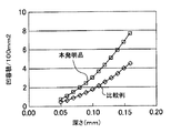
また図18には、凹み139の深さが0.08mmの本発明品1、凹み139の深さが0.12mmの本発明品2、サンドブラスト加工を施した比較例1、深さが0.09mmの溝を100本設けた比較例2それぞれのトナー汲み上げ量の計測結果を示す。なお図18中の横軸はドクタブレード116と現像ローラ115との間隔を、図18中の縦軸は現像剤の搬送量をそれぞれ示している。図18によれば、本発明品1及び2は、従来のサンドブラスト加工や溝が形成された比較例1及び2と同等以上の搬送性を有することが確認でき、またこれらの現像スリーブ132で画像評価を行なうと、ピッチムラが発生しないことも確認できた。   Also, FIG. 18 shows the product 1 of the present invention in which the depth of the recess 139 is 0.08 mm, the product 2 of the present invention in which the depth of the recess 139 is 0.12 mm, the comparative example 1 subjected to sandblasting, and the depth is 0.00. The measurement results of the amount of toner drawn up in Comparative Example 2 in which 100 grooves of 09 mm are provided are shown. The horizontal axis in FIG. 18 indicates the distance between the doctor blade 116 and the developing roller 115, and the vertical axis in FIG. 18 indicates the developer transport amount. According to FIG. 18, it can be confirmed that the products 1 and 2 of the present invention have a transportability equal to or higher than that of Comparative Examples 1 and 2 in which conventional sandblasting and grooves are formed. When the evaluation was performed, it was also confirmed that no pitch unevenness occurred.

以上、本発明の好ましい実施の形態について説明したが、本発明は上述した特定の実施形態に限定されるものではなく、上述の説明で特に限定していない限り、特許請求の範囲に記載された本発明の趣旨の範囲内において、種々の変形・変更が可能である。
例えば、本発明を適用する画像形成装置は、上述のタイプの画像形成装置に限らず、他のタイプの画像形成装置であってもよい。すなわち、本発明を適用する画像形成装置は、プリンタ、ファクシミリの単体、あるいはこれらの複合機、これらに関するモノクロ機やカラー機等の複合機であってもよい。その他、本発明を適用する画像形成装置は、電気回路形成に用いられる画像形成装置、バイオテクノロジー分野において所定の画像を形成するために用いられる画像形成装置であってもよい。
本発明の実施の形態に記載された効果は本発明から生じる最も好適な効果を列挙したに過ぎず、本発明による効果は本発明の実施の形態に記載されたものに限定されるものではない。
The preferred embodiments of the present invention have been described above. However, the present invention is not limited to the specific embodiments described above, and is described in the claims unless specifically limited by the above description. Various modifications and changes can be made within the scope of the present invention.
For example, the image forming apparatus to which the present invention is applied is not limited to the type of image forming apparatus described above, and may be another type of image forming apparatus. In other words, the image forming apparatus to which the present invention is applied may be a printer, a single facsimile, or a complex machine thereof, or a complex machine such as a monochrome machine or a color machine related thereto. In addition, the image forming apparatus to which the present invention is applied may be an image forming apparatus used for forming an electric circuit or an image forming apparatus used for forming a predetermined image in the biotechnology field.
The effects described in the embodiments of the present invention are only the most preferable effects resulting from the present invention, and the effects of the present invention are not limited to those described in the embodiments of the present invention. .

21 エンドミル(回転工具)
24 切削刃
99,115 現像剤担持体(現像ローラ)
101 画像形成装置
106Y,106M,106C,106K プロセスカートリッジ
108 潜像担持体(感光体ドラム)
109 帯電手段(帯電ローラ)
113 現像装置
126 現像剤
132 現像スリーブ
133 マグネットローラ
139 凹み
21 End mill (rotary tool)
24 Cutting blade 99,115 Developer carrier (developing roller)
101 Image forming apparatus 106Y, 106M, 106C, 106K Process cartridge 108 Latent image carrier (photosensitive drum)
109 Charging means (charging roller)
113 Developing Device 126 Developer 132 Developing Sleeve 133 Magnet Roller 139 Recess

特許第5217510号公報Japanese Patent No. 5217510

Claims (11)

内包するマグネットローラの磁力により外表面に現像剤を吸着する現像スリーブを有し、それぞれ近接対向配置された複数の現像剤担持体を備え、
前記現像スリーブの外表面に、平面視で互いに重ならないように間隔を開けて規則的または不規則的に複数設けられた凹みを有し、
前記凹みは前記現像スリーブの前記軸心に対して傾斜して形成され、互いに隣接する前記現像剤担持体の近接対向部において、前記凹みの傾斜方向が互いに逆向きとなるようにそれぞれ形成されている現像装置。
It has a developing sleeve that adsorbs the developer on the outer surface by the magnetic force of the magnet roller contained therein, and includes a plurality of developer carriers arranged in close proximity to each other,
The outer surface of the developing sleeve has a plurality of recesses provided regularly or irregularly at intervals so as not to overlap each other in plan view,
The recesses are formed to be inclined with respect to the axial center of the developing sleeve, and are formed so that the inclination directions of the recesses are opposite to each other at adjacently facing portions of the developer carrier adjacent to each other. Developing device.
請求項1記載の現像装置において、
前記現像スリーブの周方向における前記凹みの断面形状がV字形状を呈し、かつ前記現像スリーブの長手方向における前記凹みの断面形状が円弧形状であることを特徴とする現像装置。
The developing device according to claim 1,
The developing device according to claim 1, wherein a cross-sectional shape of the recess in the circumferential direction of the developing sleeve has a V shape, and a cross-sectional shape of the recess in the longitudinal direction of the developing sleeve is an arc shape.
請求項1記載の現像装置において、
前記現像スリーブの周方向における前記凹みの断面形状が円弧形状を呈し、かつ前記現像スリーブの長手方向における前記凹みの断面形状が円弧形状であることを特徴とする現像装置。
The developing device according to claim 1,
The developing device according to claim 1, wherein a cross-sectional shape of the recess in the circumferential direction of the developing sleeve has an arc shape, and a cross-sectional shape of the recess in the longitudinal direction of the developing sleeve is an arc shape.
請求項1ないし3の何れか一つに記載の現像装置において、
前記現像スリーブの周方向において互いに隣り合う前記凹み同士が該現像スリーブの長手方向に向けてずらした位置に配置されていることを特徴とする現像装置。
The developing device according to any one of claims 1 to 3,
The developing device, wherein the recesses adjacent to each other in the circumferential direction of the developing sleeve are arranged at positions shifted in the longitudinal direction of the developing sleeve.
請求項1ないし4の何れか一つに記載の現像装置において、
前記凹みはその容積が前記現像スリーブの長手方向中央部から両端部に向けて徐々に大きくなるように形成されていることを特徴とする現像装置。
The developing device according to any one of claims 1 to 4,
The developing device according to claim 1, wherein the volume of the recess is gradually increased from a longitudinal center portion of the developing sleeve toward both end portions.
請求項5記載の現像装置において、
前記凹みはその深さが前記現像スリーブの長手方向中央部から両端部に向けて徐々に深くなるように形成されていることを特徴とする現像装置。
The developing device according to claim 5, wherein
The developing device according to claim 1, wherein the depth of the recess is formed so as to gradually become deeper from a longitudinal center portion of the developing sleeve toward both end portions.
請求項5または6記載の現像装置において、
前記凹みはその平面視の面積が前記現像スリーブの長手方向中央部から両端部に向けて徐々に大きくなるように形成されていることを特徴とする現像装置。
The developing device according to claim 5 or 6,
2. The developing device according to claim 1, wherein the recess is formed so that an area in plan view is gradually increased from a longitudinal central portion of the developing sleeve toward both end portions.
請求項5ないし7の何れか一つに記載の現像装置において、
前記凹みはその単位面積当たりの個数が前記現像スリーブの長手方向中央部から両端部に向けて徐々に多くなるように形成されていることを特徴とする現像装置。
The developing device according to any one of claims 5 to 7,
The developing device according to claim 1, wherein the number of the recesses per unit area is gradually increased from a longitudinal central portion to both ends of the developing sleeve.
請求項1ないし8の何れか一つに記載の現像装置において、
前記凹みは螺旋状に配置されていることを特徴とする現像装置。
The developing device according to any one of claims 1 to 8,
The developing device according to claim 1, wherein the recesses are arranged in a spiral shape.
請求項1ないし9の何れか一つに記載の現像装置を有することを特徴とするプロセスカートリッジ。   A process cartridge comprising the developing device according to claim 1. 潜像担持体と、帯電手段と、現像装置とを有する画像形成装置において、前記現像装置として請求項1ないし9の何れか一つに記載の現像装置を有することを特徴とする画像形成装置。   An image forming apparatus having a latent image carrier, a charging unit, and a developing device, wherein the developing device includes the developing device according to any one of claims 1 to 9.
JP2014153161A 2014-07-28 2014-07-28 Developing device, process cartridge, and image forming apparatus Pending JP2016031435A (en)

Priority Applications (1)

Application Number Priority Date Filing Date Title
JP2014153161A JP2016031435A (en) 2014-07-28 2014-07-28 Developing device, process cartridge, and image forming apparatus

Applications Claiming Priority (1)

Application Number Priority Date Filing Date Title
JP2014153161A JP2016031435A (en) 2014-07-28 2014-07-28 Developing device, process cartridge, and image forming apparatus

Publications (1)

Publication Number Publication Date
JP2016031435A true JP2016031435A (en) 2016-03-07

Family

ID=55441848

Family Applications (1)

Application Number Title Priority Date Filing Date
JP2014153161A Pending JP2016031435A (en) 2014-07-28 2014-07-28 Developing device, process cartridge, and image forming apparatus

Country Status (1)

Country Link
JP (1) JP2016031435A (en)

Cited By (1)

* Cited by examiner, † Cited by third party
Publication number Priority date Publication date Assignee Title
WO2023113036A1 (en) * 2021-12-17 2023-06-22 株式会社アーケム Developing roller

Cited By (1)

* Cited by examiner, † Cited by third party
Publication number Priority date Publication date Assignee Title
WO2023113036A1 (en) * 2021-12-17 2023-06-22 株式会社アーケム Developing roller

Similar Documents

Publication Publication Date Title
JP5217510B2 (en) Developing roller, developing device, process cartridge, and image forming apparatus
US7925192B2 (en) Developing roller, developing device, process cartridge, and image forming apparatus
JP5365180B2 (en) Developing roller, developing device, process cartridge, and image forming apparatus
JP5716531B2 (en) Developing roller, developing device, process cartridge, and image forming apparatus
US8824932B2 (en) Development device, and process cartridge and image forming apparatus incorporating same
JP2012155144A (en) Developing device and image forming apparatus including the same
JP2017138351A (en) Developing device and image forming apparatus including the same
JP2011237473A (en) Development roller, development device, process cartridge and image forming device
JP6308175B2 (en) Developing device and image forming apparatus including the same
JP5439409B2 (en) Developing device and image forming apparatus including the same
JP2012168225A (en) Developing sleeve, developing roller, developing device, process cartridge, image forming apparatus, and method of manufacturing developing sleeve
JP5534412B2 (en) Developing device, and image forming apparatus and process cartridge having the same
US10108110B2 (en) Developing device
JP2016031435A (en) Developing device, process cartridge, and image forming apparatus
JP5605092B2 (en) Developing device, process cartridge, and image forming apparatus
JP5585866B2 (en) Developing device, and image forming apparatus and process cartridge having the same
JP2011100003A (en) Developing roller, developing device, process cartridge, and image forming apparatus
JP5504711B2 (en) Developing roller, developing device, process cartridge, and image forming apparatus
JP2009288581A (en) Developing device and image forming apparatus equipped with the same
JP6443368B2 (en) Developing device and image forming apparatus having the same
JP6460024B2 (en) Developing device and image forming apparatus having the same
JP6460023B2 (en) Developing device and image forming apparatus having the same
JP5640582B2 (en) Developing device, process cartridge, and image forming apparatus
JP5609447B2 (en) Developing device, process cartridge, and image forming apparatus
JP2015014809A (en) Developing device, process cartridge and image forming apparatus