JP2016023751A - Fastener - Google Patents
Fastener Download PDFInfo
- Publication number
- JP2016023751A JP2016023751A JP2014149452A JP2014149452A JP2016023751A JP 2016023751 A JP2016023751 A JP 2016023751A JP 2014149452 A JP2014149452 A JP 2014149452A JP 2014149452 A JP2014149452 A JP 2014149452A JP 2016023751 A JP2016023751 A JP 2016023751A
- Authority
- JP
- Japan
- Prior art keywords
- clip
- fastener
- head
- main body
- opening
- Prior art date
- Legal status (The legal status is an assumption and is not a legal conclusion. Google has not performed a legal analysis and makes no representation as to the accuracy of the status listed.)
- Granted
Links
- 238000003780 insertion Methods 0.000 claims abstract description 51
- 230000037431 insertion Effects 0.000 claims abstract description 51
- 239000000463 material Substances 0.000 description 23
- 229920003002 synthetic resin Polymers 0.000 description 8
- 239000000057 synthetic resin Substances 0.000 description 8
- 238000000034 method Methods 0.000 description 7
- XEEYBQQBJWHFJM-UHFFFAOYSA-N Iron Chemical compound [Fe] XEEYBQQBJWHFJM-UHFFFAOYSA-N 0.000 description 6
- 239000010985 leather Substances 0.000 description 5
- 239000004745 nonwoven fabric Substances 0.000 description 5
- 229910052742 iron Inorganic materials 0.000 description 3
- 238000012986 modification Methods 0.000 description 3
- 230000004048 modification Effects 0.000 description 3
- 239000007787 solid Substances 0.000 description 3
- 239000000853 adhesive Substances 0.000 description 2
- 230000001070 adhesive effect Effects 0.000 description 2
- 229910000831 Steel Inorganic materials 0.000 description 1
- 238000010586 diagram Methods 0.000 description 1
- 239000000428 dust Substances 0.000 description 1
- 230000001771 impaired effect Effects 0.000 description 1
- 239000005001 laminate film Substances 0.000 description 1
- 230000002093 peripheral effect Effects 0.000 description 1
- 239000011090 solid board Substances 0.000 description 1
- 239000010959 steel Substances 0.000 description 1
Images


Abstract
Description
本発明は、留め具に関し、特に、板材等の取付部品を、壁や車体である取付部に留めるための留め具に関するものである。 The present invention relates to a fastener, and more particularly to a fastener for fastening an attachment component such as a plate material to an attachment portion that is a wall or a vehicle body.
従来から、様々な物品を製造する場面において、ある物を他の物に連結あるいは固定する必要性が出てくるが、一般的には、釘やネジあるいは接着剤を使用して行われている。しかしながら、これらの釘やネジあるいは接着剤が使用できない物品や場面があることは多々あり、これらの釘やネジ等が使用できない物品や場面では、特別な留め具が必要になる。例えば、裏側に作業空間が存在しない壁や車体である取付部に、表面に傷を付けたり加工したりしたくない板材等の取付部品を留める場合に適した方法あるいは留め具が、例えば特許文献1等において種々提案されてきている。 Conventionally, there is a need to connect or fix one object to another in a scene where various articles are manufactured, but it is generally performed using nails, screws, or adhesives. . However, there are many articles and scenes where these nails, screws, or adhesives cannot be used, and special fasteners are required for articles and scenes where these nails, screws, etc. cannot be used. For example, there is a method or fastener suitable for fastening a mounting part such as a plate material that does not want to be scratched or processed on a mounting part that is a wall or a vehicle body having no work space on the back side, for example, Patent Document 1 etc. have been proposed variously.
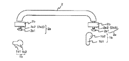
特許文献1で提案されている「着脱部材の固定構造」は、図6及び図7に示すように、「被着脱体1には、座ぐり部1aを形成すると共にその座ぐり部底面に、そのほぼ中央部に小径部1b1を位置させただるま形透孔1bを穿設しておく。着脱部材2には、きのこ形支持軸2aを形成すると共にその軸部2a2に雄ねじ部2a3を形成し、それにねじつまみ2bを螺入しておく。そして、きのこ形支持軸2aの笠部2a1をだるま形透孔大径部1b2に挿通させた後、軸部2a2をだるま形透孔小径部1b1内に移動させ、ねじつまみ2bを締付けることにより、それを座ぐり部1a内に収めると共に笠部2a1とねじつまみ2bとで座ぐり部1a底面を表裏から挟持し着脱部材2を被着脱体1に固定する」ものである。
As shown in FIGS. 6 and 7, the “fixing structure of the detachable member” proposed in Patent Document 1 is as follows: “The body 1 to be attached / detached is formed with a
この特許文献1で提案されている「着脱部材の固定構造」では、「きのこ形支持軸2aの笠部2a1をだるま形透孔大径部1b2に挿通させた後、軸部2a2をだるま形透孔小径部1b1内に移動させ、ねじつまみ2bを締付ける」ことが必要で、しかもこの締付け作業を行う空間も必要である。
In the “fixing structure of the detachable member” proposed in Patent Document 1, “the barrel portion 2a1 of the mushroom-
そこで、これらの締付け作業や空間が必要でなくなるような技術が、特許文献2において提案されている。
Therefore,
特許文献2には、図8の(a)に示すような、「被保持物を挟持して保持するための頭部と、パネル板の取付孔に挿入して嵌着するための胴部とからなり、当該胴部が一対の弾性脚部と中央柱部とを具備してなる保持クリップ」が提案されている。この「保持クリップ」(図8の(a)中では符号40で示してある)は、図8の(a)に示すように、取り付けられるべき板材50に形成した、大穴51と小穴52を連続部53で連続させたダルマ穴のうち、大穴51に頭部を挿入して、そのままの状態で当該保持クリップ40の軸を、連続部53を通して小穴52に移行させることにより、小穴52に当該保持クリップ40の頭部を嵌着するものである。
In
これによって、当該保持クリップ40は、板材50を取付対象である鉄板54の挿通穴54aに対して固定できるのであるが、取り付けられた板材50に問題が発生する。つまり、この板材50の表面(図8の(a)では、図示右側の面)がそのまま使用されるものである場合に、頭部を挿入するだけに使用された大穴51は、そのまま表面に露出してしまうことである。この保持クリップ40によって板材50を鉄板54の挿通穴54aに対して固定したときを平面的にみてみると、図8の(b)に示すような状態になることと考えられる。
As a result, the
この図8の(b)に示すような状態では、保持クリップ40の頭部を挿入するだけに使用された大穴51が表面に露出することになり、この露出している大穴51は、板材50が表装材である場合には非常に見栄えが悪いだけでなく、当該大穴51に他の物が引っ掛かったり、ゴミが溜まったりして、製品として非常に不都合なものとなるのである。そこで、従来では、当該大穴51を隠すために、保持クリップを取付けた後、当該保持クリップの頭部側の板材に不織布や皮シート等の装飾材を貼る、という手間の掛かる作業を行って対処している。
In the state shown in FIG. 8B, the
ところで、この種のクリップを使用して、取付対象である取付部に取付部品を取り付けるにあたっては、この取付部品の厚さに応じて、「軸」の長さを調整したクリップが必要となる。つまり、シート状の表装材や中実の板材のように、厚さの薄いものが取付部品である場合は、「軸」が短いクリップが採用されるし、プラスチック製段ボール等(断面がハーモニカ状)の中空構造板のように、厚さの厚いものであると、「軸」が長いクリップが採用されることになって、取付部品の種類や厚さに応じたクリップを用意しなければならない。クリップの「軸」の長さが変われば、クリップ自体やその「軸」の強度試験を行う必要があり、取付部品の種類に応じたクリップを用意するためには、時間と労力が多く掛かることになる。 By the way, when using this type of clip to attach an attachment part to an attachment part that is an attachment object, a clip in which the length of the “shaft” is adjusted according to the thickness of the attachment part is required. In other words, when a thin component such as a sheet-like cover material or solid plate material is a mounting part, a clip with a short “shaft” is used, and plastic corrugated cardboard or the like (having a harmonica-like cross section) If the material is thick like a hollow structure plate in (), a clip with a long "shaft" will be used, and a clip corresponding to the type and thickness of the mounting part must be prepared. . If the length of the “shaft” of the clip changes, it is necessary to perform a strength test on the clip itself and its “shaft”, and it takes a lot of time and labor to prepare a clip according to the type of mounting part. become.
一般のクリップの軸の長さは、中実の板材の肉厚に合わせてあるので、短いものである。しかし、プラスチック製段ボール等の中空構造板の肉厚は、中実の板材の肉厚よりも厚いものであり、軸の長さが短い一般のクリップを取付けるのは困難である。この軸の長さが短いクリップを取付ける為に、中空構造板を押し圧して肉厚を薄くする加工を行えば、クリップを取付けることが可能にはなるが、クリップを中空構造板に取付けても、引き抜き強度が不足して、クリップが中空構造板から外れてしまうという虞が生ずる。 The length of the shaft of a general clip is short because it matches the thickness of a solid plate material. However, the thickness of a hollow structure board such as plastic corrugated cardboard is thicker than that of a solid board, and it is difficult to attach a general clip having a short shaft length. To attach a clip with a short shaft length, it is possible to attach the clip by pressing the hollow structure plate to reduce the wall thickness, but even if the clip is attached to the hollow structure plate There is a fear that the pulling strength is insufficient and the clip is detached from the hollow structure plate.
そこで、本発明者等は、保持クリップ40を使用して、板材50を取付対象である鉄板54の挿通穴54aに対して固定した際に、取り付けられた板材50に大穴51が表面に露出するという問題が発生しないようにするとともに、取付部品の種類や厚さに応じたクリップを用意する必要性をなくすためにはどうしたらよいか、について種々検討を重ねてきた結果、本発明を完成したのである。
Accordingly, when the present inventors use the
すなわち、本発明の目的とするところは、クリップを介して取付部品を取付部に留めることができることは勿論、取付部品の種類や厚さに応じたクリップを用意する必要がなくて常に一般的なクリップを使用でき、取付部品にクリップ係止のための「だるま穴」を形成する必要がなく、しかも、留めが完了した際に、だるま穴を構成していた大穴のような「開口部」が取付部品の表面に残らないようにすることのできる留め具を提供することにある。 That is, the object of the present invention is that the attachment part can be fastened to the attachment part via the clip, and it is not always necessary to prepare a clip according to the type and thickness of the attachment part. The clip can be used, and it is not necessary to form a “dar hole” for locking the clip on the mounting part, and when the fastening is completed, there is an “opening” like a large hole that constitutes the dull hole. It is an object of the present invention to provide a fastener that can be prevented from remaining on the surface of a mounting part.
上記課題を解決するために、本願発明の請求項1に留め具は、取付部品の開口内に収容されるクリップを介して、前記取付部品を取付部に留めるために、前記クリップの頭部を収容して保持する本体部を備えた留め具であって、前記本体部は、前記取付部品の開口内に収容可能に形成されると共に、前記取付部品の開口周辺を支持する傘部を備え、さらに、前記本体部の側壁には、前記クリップの頭部を前記本体部の内部へ向けて挿入可能な挿入開口を、前記本体部の底壁には、前記頭部を支持している軸を案内し、当該頭部を前記本体部の内部へ収容する長孔を備えたことを特徴とする。 In order to solve the above-mentioned problem, the fastener according to claim 1 of the present invention is configured so that the head portion of the clip is attached to the attachment portion via the clip accommodated in the opening of the attachment component. A fastener provided with a main body part that accommodates and holds the main body part, the main body part being formed so as to be able to be accommodated in an opening of the attachment part, and an umbrella part supporting the periphery of the opening of the attachment part, Furthermore, the side wall of the main body has an insertion opening through which the head of the clip can be inserted into the main body, and the bottom wall of the main body has an axis that supports the head. A long hole is provided for guiding and accommodating the head in the main body.
上記特徴によれば、クリップの頭部を挿入開口から挿入して留め具内に収容することで、このクリップを介して取付部品を取付部に留めることができる。さらに、クリップの頭部を挿入開口から挿入する方法には、様々な方法が考えられるが、例えば、取付部品の開口周辺に位置する留め具の傘部を変形させるようにして、留め具を押し上げれば、取付部品の開口から、留め具の挿入開口を飛び出させることができるので、その飛び出した挿入開口へクリップの頭部を容易に挿入できる。 According to the said characteristic, an attachment component can be fastened to an attachment part via this clip by inserting the head of a clip from an insertion opening, and accommodating in a fastener. Furthermore, there are various methods for inserting the clip head from the insertion opening. For example, the clip is pushed up by deforming the umbrella portion of the fastener located around the opening of the attachment part. Then, since the insertion opening of the fastener can be protruded from the opening of the mounting part, the head of the clip can be easily inserted into the protruding insertion opening.
また、取付部品がプラスチック製段ボール等の中空構造板であれば、中空構造板の壁部自体は薄肉なので、外部からの圧力に対して適度に凹ませることができる。また、上記以外の中空構造板であっても、その材質に柔軟性があれば、外部からの圧力に対して適度に凹ませることができる。そのため、クリップの頭部によって取付部品の開口周辺を凹ませて、留め具の挿入開口を露出させることで、クリップの頭部を挿入開口へと容易に挿入できる。 Further, if the mounting part is a hollow structure plate such as a plastic corrugated cardboard, the wall portion of the hollow structure plate itself is thin, so that it can be appropriately recessed with respect to external pressure. Moreover, even if it is a hollow structure board other than the above, if the material has a softness | flexibility, it can be dented moderately with respect to the pressure from the outside. Therefore, the head of the clip can be easily inserted into the insertion opening by denting the periphery of the opening of the attachment part with the head of the clip and exposing the insertion opening of the fastener.
また、留め具を取り付けるための取付部品の開口は、従来のように「だるま穴」ではなく、さらに、取付部品の開口が留め具の傘部によって隠されるので、特に取付部品が表装材である場合には、従来のように、不織布や皮シート等の装飾材を開口に貼る必要がないので、手間がかからず、取付部品の外観を損なわないのである。 Further, the opening of the attachment part for attaching the fastener is not a “dar hole” as in the prior art, and furthermore, since the opening of the attachment part is concealed by the umbrella part of the fastener, the attachment part is particularly a cover material. In such a case, it is not necessary to attach a decorative material such as a nonwoven fabric or a leather sheet to the opening as in the conventional case, so that it does not take time and does not impair the appearance of the mounting part.
また、従来は、取付部品の開口にクリップの頭部を直接嵌着させて保持するものなので、取付部品の種類や厚さに応じて、クリップの軸の長さを調節する必要があった。しかし、本願発明によれば、留め具を介して取付部品にクリップを間接的に保持させる構成であるから、取付部品の種類や厚さに関係なく、クリップを留め具に収容して保持させることができ、従来のようにクリップの軸の長さを調節する必要がなく、一般的なクリップをそのまま利用することができる。 Conventionally, since the head of the clip is directly fitted and held in the opening of the attachment part, it is necessary to adjust the length of the shaft of the clip according to the type and thickness of the attachment part. However, according to the present invention, since the clip is indirectly held by the attachment part via the fastener, the clip is accommodated and held in the fastener regardless of the type and thickness of the attachment part. Therefore, it is not necessary to adjust the length of the clip shaft as in the prior art, and a general clip can be used as it is.
さらに、本願発明の請求項2に係る留め具は、前記長孔内に、当該長孔の幅を狭くするくびれ部を設けたことを特徴とする。
Furthermore, the fastener according to
上記特徴によれば、長孔の幅を狭くするくびれ部によって、留め具内に収容されたクリップが、長孔を介して外へ不用意に脱落してしまうことを防止できる。 According to the said characteristic, it can prevent that the clip accommodated in the fastener falls out carelessly outside through a long hole by the constriction part which narrows the width | variety of a long hole.
本願発明の留め具は、クリップを介して取付部品を取付部に留めることができることは勿論、取付部品の種類や厚さに応じたクリップを用意する必要がなくて常に一般的なクリップを使用でき、取付部品にクリップ係止のための「だるま穴」を形成する必要がなく、しかも、留めが完了した際に、だるま穴を構成していた大穴のような「開口部」が取付部品の表面に残らないようにすることができる。 The fastener of the present invention can always use a general clip without having to prepare a clip according to the type and thickness of the mounting part, as well as being able to fasten the mounting part to the mounting part via the clip. There is no need to form a “dar hole” for clip locking on the mounting part, and when the fastening is completed, an “opening” like a large hole that constitutes the dull hole is formed on the surface of the mounting part. It can be made not to remain.
100 留め具
110 本体部
111 側壁
112 底壁
120 挿入開口
130 長孔
160 傘部
200 取付部品
210 開口
300 取付部
310 留め孔
400 クリップ
410 頭部
420 軸
DESCRIPTION OF
以下に、本願発明の実施の形態について、図面を用いて説明する。 Embodiments of the present invention will be described below with reference to the drawings.
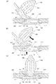
まず、図1には、本願発明の留め具100の使用態様の一例を示す。この留め具100は、クリップ400を介して、板材等の取付部品200を、壁や車体の一部である取付部300に留めるために使用される。具体的には、まず、取付部品200の表側(図面上手前側)から、開口210に留め具100の本体部110を挿入する。そして、詳しくは後述するが、本体部110の挿入開口120へ、クリップ400の頭部410を挿入して、本体部110内部に頭部410を収容して保持する。すると、クリップ400は、留め具100を介して開口210内に収容されて固定される。次に、取付部品200と一体となったクリップ400の本体部430を、取付部300の留め孔310に挿入することで、取付部品200はクリップ400を介して取付部300に留められる。
First, FIG. 1 shows an example of how the
ところで、クリップ400は、一般的に使用され市販もされているもので種々なタイプのものがあるが、基本的には、図1や図4に示すように、何処か(本発明では留め具100の本体部110内)に保持される頭部410と、この頭部410と一体的な軸420と、この軸420の先に一体化されて、取付部300の留め孔310内に係合される本体部430とからなり、全体を合成樹脂等で一体成形したものである。また、この種のクリップ400は、取付部300の表面に当接して、本体部430のそれ以上の嵌入を阻止する当接部440を有していることも一般的である。
Incidentally, the
また、クリップ400の頭部410は、本体部110への収容だけに使用されるものであり、軸420は、長孔130及び軸受孔113へ(図2及び図3参照)の挿通だけに使用される部分であるから、その断面形状が四角であっても他の形状であってもよいが、挿入時の方向性が無くなることから、「円」にするのが好ましい。
Further, the
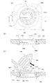
では、次に、図2を参照して、本願発明の留め具100の構成について詳しく説明する。
Next, the configuration of the
図2(a)に示すように、留め具100は、円筒形の本体部110と、平面視略円形の平坦な薄板状の傘部160からなる。本体部110は、傘部160の裏面と、側壁111と、底壁112とによって、クリップ400の頭部410を収容可能な収容部114を形成している。そして、側壁111の一部には、クリップ400の頭部410を、本体部110の内部へ挿入するための挿入開口120が設けられている。この挿入開口120は、本体部110の側方へ向けて開口し、内部の収容部114まで連通したもので、その高さH1(図2(d)参照)は、頭部410が挿入出来るように、頭部410の最大高さ以上に設定され、また、幅L1は頭部410の最大幅(直径)以上に設定されている。なお、合成樹脂製の留め具は、ある程度の柔軟性があるので、幅L1が頭部410の最大幅(直径)と同じ、又は小さくても、頭部410を挿入することができる。
As shown in FIG. 2A, the
また、本体部110の底壁112には、底壁112の外周縁から底壁112の中央の軸受孔113まで延びる長孔130が設けられている。そして、この長孔130は挿入開口120と連通している。そのため、長孔130は、挿入開口120にクリップ400の頭部410を挿入した際に、頭部410を支持している軸420を、本体部110の中央の軸受孔113へと案内することができる。
The
このように、長孔130及び軸受孔113は、クリップ400の軸420を案内して収容するものなので、図2(e)に示すように、軸受孔113の最大幅(直径)L2は軸420の最大幅(直径)以上に、長孔130の幅L3は軸420の最大幅(直径)以上に設定されている。なお、合成樹脂製の留め具は、ある程度の柔軟性があるので、幅L3が軸420の最大幅(直径)と同じ、又は小さくても、軸420を案内して収容することができる。
Thus, since the
ここで、本実施例では、長孔130の幅L3を、軸受孔113の幅L2より狭くなるように、長孔130の両端にくびれ部150を設けている。つまり、このくびれ部150によって長孔130の幅を狭くすることで、軸受孔113内に収容された軸420が、長孔130から抜け出にくくし、収容されたクリップ400が、留め具100から不用意に脱落してしまうことを防止している。なお、くびれ部150の先端部に面取りを形成することで、クリップ400の軸420を挿入しやすくしてもよい。
Here, in the present embodiment, the
また、くびれ部150の裏面側は、図2(f)に示すように、挿入開口120の入口側から、本体部110の収容部114へ向けて傾斜した傾斜面151となっている。また、図2(e)に示すように、両側の傾斜面151は軸受孔113に向けて、徐々に幅が狭くなるようになっているので、底壁112との境目が、略ハの字状に広がる段差部152になっている。そして、両側の傾斜面151間の最大幅L4は、クリップ400の頭部410の最大幅(直径)以上に設定されている。詳しくは後述するが、頭部410を挿入開口120に挿入する際に、頭部410が当接する部分は傾斜面151になる。そのため、傾斜面151が、収容部114へ向けて傾斜し、さらに、収容部114へ向けて幅が狭くなるように、両側の段差部152が略ハの字状になっていることで、傾斜面151に当接している頭部410が、収容部114の中心へ向けて誘導されやすくなる。
Further, as shown in FIG. 2F, the back surface side of the
また、この収容部114内には、傘部160の裏面側から突出するように、リブ140が設けられている。このリブ140は、任意に設けるものであり、本体部110内部に収容されたクリップ400の頭部410に当接して、頭部410の上下方向のガタつきを防止するものである。特に、本体部110が対象とするクリップは、一般的な様々な種類のクリップであるので、どのクリップの頭部であっても収容部114内に収容できるように、収容部114の高さは大きめに設定する場合がある。そのため、クリップの種類によっては、頭部が収容部114内で上下方向にガタつく可能性もあるので、リブ140によってガタつきを防止するのである。勿論、収容される頭部410に合わせて、リブ140の高さを任意に変更してもよい。
Further, a
なお、留め具100は合成樹脂製であり、一体成形されている。そして、傘部160の縁部161は外力を加えることで変形し、かつ復元可能な程度の弾性を有するものとする。また、縁部161は、先端ほど裏側が薄肉になっており、吸盤状になっている。
The
では、次に、図3から図4を参照して、留め具100の使用方法について詳しく説明する。
Next, a method of using the
ここで、本願発明に係る留め具100が対象としている取付部品200については種々なものがあるが、一般的には、この取付部品200としては、例えば不織布や皮シートのような、薄いシート状の表装材や、プラスチック製段ボール(断面がハーモニカ状になっている)等の中空構造板や、中実の合成樹脂製板や鋼板のように、厚さのある板状の表装材等がある。勿論、この厚さのある板状物や、種々な積層板の表面に、上記不織布や皮シート、あるいはラミネートフィルムのような薄いシート状物を貼ったり固定したりした表装材も、本発明に係る留め具100が対象としている取付部品200である。
Here, there are various types of
そして、以下に説明する図3及び図4で使用している取付部品200は、プラスチック製段ボール等の中空構造板のように、厚さのある板状の表装材であり、開口210の周囲でクリップ400の頭部410によって少し押し潰されるように弾性変形可能なものである。
The mounting
では、まず始めに、図3に示すように、取付部品200に設けられた開口210に、留め具100の本体部110を嵌め込む。開口210は、本体部110を嵌め込むことができるように、本体部110より僅かに大きい円形形状をしている。また、開口210が本体部110より僅かに小さい円形形状をしていても、開口210を弾性変形させて、本体部110を嵌め込んでもよい。
First, as shown in FIG. 3, the
そして、開口210に留め具100が収容された状態では、図3に示すように、取付部品200の表側に傘部160の縁部161が当接している。そのため、この縁部161が、開口210を覆い隠すと共に、留め具100がこれ以上、奥へ押し込まれないようにしている。
In the state in which the
次に、図3(b)の状態から、図4(a)に示すように、留め具100の挿入開口120へ、クリップ400の頭部410を挿入しようとする。しかし、挿入開口120は取付部品200の開口210に塞がれており、開口210と挿入開口120との間には、頭部410が入るだけの隙間がない。そこで、図4(b)に示すように、傘部160側から力を加えて留め具100を押し上げ、挿入開口120を開口210から飛び出させて露出させる(以下、「操作1」と呼ぶ)。なお、縁部161は合成樹脂製なので容易に変形することができ、さらに、先端ほど裏側が薄肉になっているので、更に変形しやすくなっている。
Next, from the state of FIG. 3B, the
そして、さらに挿入開口120を露出させて、頭部410を挿入しやすくするために、頭部410を開口210の周囲に押し当て、図4(b)に示すように、取付部品200の開口210の周囲を、僅かに凹むように弾性変形させる(以下、「操作2」と呼ぶ)。
Then, in order to further expose the
そして、この状態で、クリップ400の頭部410を挿入開口120に挿入して、クリップ400を留め具100の中心へ押し込んでいくと、図4(b)から図4(c)に示すように、軸420は長孔130によって、軸受孔113まで案内されて移動すると共に、一方の頭部410は挿入開口120から収容部114まで移動して収容されることになる。
In this state, when the
なお、頭部410を挿入開口120へと押し込んでいく際に、初めに開口210から飛び出すように露出する箇所は傾斜面151であるから、この傾斜面151に頭部410を引っ掛け、後は傾斜面151及び長孔130に沿って押し込んでいけば、容易にクリップ400を留め具100に収容させることができる。また、この傾斜面151は、縁部161の復元力と取付部品200の復元力によって、頭部410の裏面側から最も圧力を受ける部分でもある。そこで、この部分を傾斜面151としたことで、圧力を傾斜に沿って逃しやすくなり、その傾斜の先にある収容部114へ向けて、頭部410を移動させやすくなる。
Note that when the
そして、クリップ400の留め具100への取付が完了すると、縁部161及び取付部品200が復帰して、図4(c)に示す状態となる。その後、クリップ400の本体部430を取付部300の留め孔310(図1参照)に嵌入させれば、取付部品200を取付部300に留めて固定することができる。
Then, when the attachment of the
このように、本願発明の留め具100は合成樹脂で成形されているので、留め具100の縁部161が弾性変形して、図4(b)に示すように、挿入開口120を取付部品200の開口210から露出させて、頭部410を挿入開口120へ挿入させることができる。さらに、取付部品200が、プラスチック製段ボール等の中空構造板であれば、中空構造板の壁部自体は薄肉なので、外部からの圧力に対して適度に凹むことができる。よって、取付部品200にクリップ400の頭部410を押し当てて、図4(b)に示すように、開口210の周囲が凹むように弾性変形させ、頭部410を挿入開口120へ容易に挿入することができる。
As described above, since the
ところで、図4に示す本実施例では、留め具100の本体部110の高さと、取付部品200の厚さ方向の高さが等しくなっているが、これに限定されることは無く、両者は異なっていてもよい。ただ、一般的には、留め具100の内部に収容されたクリップ400が抜け落ちないようにするために、図4(c)に示すように、側方へ開口した挿入開口120が開口210の内壁で塞がれている状態が望ましい。そのため、本体部110の高さは、取付部品200の厚さ方向の高さと等しいか、又は低いことが望ましい。
In the present embodiment shown in FIG. 4, the height of the
しかし、挿入開口120が開口210の内壁で塞がれているため、頭部410を挿入開口120に挿入することが困難になる可能性がある。そこで、挿入開口120を一時的に開口210から露出させて、頭部410を挿入できるように、弾性変形可能な縁部161を設けたのである。
However, since the
また、この縁部161は、取付部品200の開口210に留め具100が収容された際に、取付部品200の表面に当接して、留め具100がそれ以上挿入されないようにするもので、言い換えるならば、縁部161は、留め具100と取付部品200の位置関係を保持する保持部材でもある。したがって、縁部161は図4に示すように、傘部160の縁部のフランジ状の形態に限られず、挿入開口120を開口210から飛び出させて露出するために、留め具100と取付部品200の位置関係を一時的に変更可能な保持部材であれば、その他の態様であってもよい。
In addition, the
なお、図4(b)に示す本実施例では、操作1と操作2の両方を行うことで、頭部410を挿入開口120へ容易に挿入させていた。しかしながら、操作1又は操作2のいずれか一方のみで、挿入開口120に頭部410を挿入させることが出来るならば、本実施例のように、操作1と操作2の両方を行う必要はない。
In the present embodiment shown in FIG. 4B, the
また、留め具を取り付けるための取付部品200の開口210は、従来のように「だるま穴」ではなく、さらに、取付部品200の開口210が留め具100の傘部160によって隠されるので、特に取付部品200が表装材である場合には、従来のように、不織布や皮シート等の装飾材を開口に貼る必要がないので、手間がかからず、取付部品200の外観を損なわないのである。
Further, the
また、従来は、取付部品の開口にクリップの頭部を直接嵌着させて保持するものなので、取付部品の種類や厚さに応じて、クリップの軸の長さを調節する必要があった。しかし、本願発明によれば、留め具100を介して取付部品200にクリップを間接的に保持させる構成であるから、取付部品200の種類や厚さに関係なく、クリップ400を留め具100の本体部110に収容して保持させることができ、従来のようにクリップの軸の長さを調節する必要がなく、一般的なクリップをそのまま利用することができるのである。
Conventionally, since the head of the clip is directly fitted and held in the opening of the attachment part, it is necessary to adjust the length of the shaft of the clip according to the type and thickness of the attachment part. However, according to the present invention, since the clip is indirectly held by the
なお、図4では、クリップ400の取付時に、当接部440が留め具100に当接して変形している。しかし、これに限定されることはなく、例えば、当接部440の長さが短いものを使用したり、頭部410の挿入開口120への挿入角度を変えれば、当接部440が変形しなくても、何ら問題なく、クリップ400を留め具100に取り付けることができる。
In FIG. 4, when the
では、次に、本願発明の他の変形例について、図5を参照して説明する。なお、図5で示す変形例では、留め具100aの底壁112aの一部に、底部挿入開口121aを設けた点で、図1から図4に示す留め具100と異なるだけで、他の構成は留め具100と同一である。
Next, another modification of the present invention will be described with reference to FIG. 5 differs from the
図5(a)に示すように、留め具100aの底壁112aの一部であって、長孔130aに隣接する箇所を切り欠くように、底部挿入開口121aが設けられている。この底部挿入開口121aは、上方(底壁112aに対して垂直方向)へ向けて開口しており、図5(b)に示すように、挿入開口120aと連通している。また、底部挿入開口121aの最大幅L5は、クリップ400の頭部410の最大幅(直径)以上に設定されている。なお、合成樹脂製の留め具は、ある程度の柔軟性があるので、幅L5が頭部410の最大幅(直径)と同じ、又は小さくても、頭部410を挿入することができる。
As shown in FIG. 5A, a
そして、図5(c)に示すように、クリップ400の頭部410を、上方へ開口した底部挿入開口121aから挿入して、そのまま挿入開口120aへと移動させる。一方、軸420は長孔130aによって、軸受孔113aまで案内されて移動する。
And as shown in FIG.5 (c), the
なお、頭部410は底部挿入開口121aから挿入することができるので、縁部161aを弾性変形させて留め具100aを押し上げたり(操作1)、頭部410を取付部品200に押し当てて弾性変形させること(操作2)を行う必要はない。しかし、状況により、操作1や操作2を適宜行ってもよい。
Since the
なお、本願発明の留め具は、上記の実施例に限定されず、特許請求の範囲に記載された範囲、実施形態の範囲で、種々の変形例、組み合わせが可能であり、これらの変形例、組み合わせもその権利範囲に含むものである。 The fastener of the present invention is not limited to the above-described examples, and various modifications and combinations are possible within the scope of the claims and the scope of the embodiments. Combinations are also included in the scope of their rights.
Claims (2)
前記本体部は、前記取付部品の開口内に収容可能に形成されると共に、前記取付部品の開口周辺を支持する傘部を備え、
さらに、前記本体部の側壁には、前記クリップの頭部を前記本体部の内部へ向けて挿入可能な挿入開口を、
前記本体部の底壁には、前記頭部を支持している軸を案内し、当該頭部を前記本体部の内部へ収容する長孔を備えたことを特徴とする留め具。 In order to fasten the attachment part to the attachment part via the clip accommodated in the opening of the attachment part, the fastener includes a main body part that accommodates and holds the head of the clip,
The main body is formed so as to be accommodated in the opening of the mounting part, and includes an umbrella part that supports the periphery of the opening of the mounting part.
Further, the side wall of the main body part has an insertion opening through which the head of the clip can be inserted toward the inside of the main body part.
A fastener, characterized in that a bottom wall of the main body portion is provided with a long hole that guides a shaft supporting the head portion and accommodates the head portion inside the main body portion.
Priority Applications (1)
| Application Number | Priority Date | Filing Date | Title |
|---|---|---|---|
| JP2014149452A JP6437229B2 (en) | 2014-07-23 | 2014-07-23 | Fastener |
Applications Claiming Priority (1)
| Application Number | Priority Date | Filing Date | Title |
|---|---|---|---|
| JP2014149452A JP6437229B2 (en) | 2014-07-23 | 2014-07-23 | Fastener |
Publications (2)
| Publication Number | Publication Date |
|---|---|
| JP2016023751A true JP2016023751A (en) | 2016-02-08 |
| JP6437229B2 JP6437229B2 (en) | 2018-12-12 |
Family
ID=55270691
Family Applications (1)
| Application Number | Title | Priority Date | Filing Date |
|---|---|---|---|
| JP2014149452A Active JP6437229B2 (en) | 2014-07-23 | 2014-07-23 | Fastener |
Country Status (1)
| Country | Link |
|---|---|
| JP (1) | JP6437229B2 (en) |
Cited By (1)
| Publication number | Priority date | Publication date | Assignee | Title |
|---|---|---|---|---|
| GB2591162A (en) * | 2019-10-15 | 2021-07-21 | Lf Fasthouse Ltd | An improved building system |
Citations (4)
| Publication number | Priority date | Publication date | Assignee | Title |
|---|---|---|---|---|
| JPS58151708U (en) * | 1982-04-07 | 1983-10-11 | 株式会社ニフコ | Fastener |
| JPS61204012U (en) * | 1986-06-09 | 1986-12-22 | ||
| JP2004270794A (en) * | 2003-03-07 | 2004-09-30 | Togo Seisakusho Corp | Clip |
| JP2006220267A (en) * | 2005-02-14 | 2006-08-24 | Nippon Pop Rivets & Fasteners Ltd | Attachment device for attaching window glass or the like to car body or the like |
-
2014
- 2014-07-23 JP JP2014149452A patent/JP6437229B2/en active Active
Patent Citations (4)
| Publication number | Priority date | Publication date | Assignee | Title |
|---|---|---|---|---|
| JPS58151708U (en) * | 1982-04-07 | 1983-10-11 | 株式会社ニフコ | Fastener |
| JPS61204012U (en) * | 1986-06-09 | 1986-12-22 | ||
| JP2004270794A (en) * | 2003-03-07 | 2004-09-30 | Togo Seisakusho Corp | Clip |
| JP2006220267A (en) * | 2005-02-14 | 2006-08-24 | Nippon Pop Rivets & Fasteners Ltd | Attachment device for attaching window glass or the like to car body or the like |
Cited By (2)
| Publication number | Priority date | Publication date | Assignee | Title |
|---|---|---|---|---|
| GB2591162A (en) * | 2019-10-15 | 2021-07-21 | Lf Fasthouse Ltd | An improved building system |
| GB2591162B (en) * | 2019-10-15 | 2023-11-22 | Lf Fasthouse Ltd | An improved building system |
Also Published As
| Publication number | Publication date |
|---|---|
| JP6437229B2 (en) | 2018-12-12 |
Similar Documents
| Publication | Publication Date | Title |
|---|---|---|
| US8899374B2 (en) | Speaker unit and speaker unit mounting structure | |
| JP6255033B2 (en) | Stop | |
| US7584573B2 (en) | Glass fixing grommet | |
| US7267385B2 (en) | Vehicle trim locating and attachment system | |
| US9713384B1 (en) | Frame structure of net chair-back | |
| JP2015093601A (en) | Decorative component | |
| JP6437229B2 (en) | Fastener | |
| JP2007147060A (en) | Component mounting device | |
| JP5552464B2 (en) | Assembly structure for vehicle interior materials | |
| US9838578B2 (en) | Frame, assembling set and camera assembly set | |
| JP2011223650A (en) | Fixing structure for harness protectors | |
| JP2009023438A (en) | Tonneau cover device | |
| JP2010254247A (en) | Speaker apparatus for use in vehicle | |
| JP6393103B2 (en) | Fasteners for fastening mounting parts to the mounting part | |
| JP3162783U (en) | Round seat unit for doors | |
| KR20150022546A (en) | Mounting structure of ornament | |
| US20150233143A1 (en) | Handle | |
| KR20120016400A (en) | Mounting member for furniture goods | |
| US20240035501A1 (en) | Fastener Clip | |
| JP2014237944A (en) | Fixture panel | |
| JP2007262885A (en) | Hollow section installing structure and installing method | |
| KR20140050134A (en) | Reusable mounting clip | |
| KR101218818B1 (en) | Quick-clamping assembly | |
| US11266240B2 (en) | Drawer assembly | |
| JP5397708B2 (en) | Parts mounting structure |
Legal Events
| Date | Code | Title | Description |
|---|---|---|---|
| A621 | Written request for application examination |
Free format text: JAPANESE INTERMEDIATE CODE: A621 Effective date: 20170626 |
|
| A131 | Notification of reasons for refusal |
Free format text: JAPANESE INTERMEDIATE CODE: A131 Effective date: 20180515 |
|
| TRDD | Decision of grant or rejection written | ||
| A01 | Written decision to grant a patent or to grant a registration (utility model) |
Free format text: JAPANESE INTERMEDIATE CODE: A01 Effective date: 20181023 |
|
| A61 | First payment of annual fees (during grant procedure) |
Free format text: JAPANESE INTERMEDIATE CODE: A61 Effective date: 20181114 |
|
| R150 | Certificate of patent or registration of utility model |
Ref document number: 6437229 Country of ref document: JP Free format text: JAPANESE INTERMEDIATE CODE: R150 |
|
| R250 | Receipt of annual fees |
Free format text: JAPANESE INTERMEDIATE CODE: R250 |
|
| R250 | Receipt of annual fees |
Free format text: JAPANESE INTERMEDIATE CODE: R250 |