JP2016019986A - Plasma welding torch - Google Patents
Plasma welding torch Download PDFInfo
- Publication number
- JP2016019986A JP2016019986A JP2014144029A JP2014144029A JP2016019986A JP 2016019986 A JP2016019986 A JP 2016019986A JP 2014144029 A JP2014144029 A JP 2014144029A JP 2014144029 A JP2014144029 A JP 2014144029A JP 2016019986 A JP2016019986 A JP 2016019986A
- Authority
- JP
- Japan
- Prior art keywords
- flow path
- cooling water
- electrode
- shield gas
- water flow
- Prior art date
- Legal status (The legal status is an assumption and is not a legal conclusion. Google has not performed a legal analysis and makes no representation as to the accuracy of the status listed.)
- Pending
Links
Images


Landscapes
- Arc Welding In General (AREA)
Abstract
【課題】先端部の小型化を図ったプラズマ溶接トーチを提供する。
【解決手段】本発明のプラズマ溶接トーチ1は、第1の冷却水流路W1乃至第7の冷却水流路W7と第1のシールドガス流路G1乃至第3のシールドガス流路G3とのそれぞれの流路が、プラズマ溶接トーチ1の先端部方向に階段状に、電極3に近付くように設けられている。即ち、第1の冷却水流路W1乃至第7の冷却水流路W7と第1のシールドガス流路G1乃至第3のシールドガス流路G3とのそれぞれの流路において、プラズマ溶接トーチ1の基端部側の流路と電極3との距離よりも、プラズマ溶接トーチ1の先端部側の流路と電極3との距離の方が、短く設けられている。この結果、プラズマ溶接トーチ1の先端部の直径を小さくすることができ、プラズマ溶接トーチ1の小型化を図ることができる。
【選択図】図4Disclosed is a plasma welding torch in which the tip is reduced in size.
A plasma welding torch 1 according to the present invention includes a first cooling water channel W1 to a seventh cooling water channel W7 and a first shield gas channel G1 to a third shield gas channel G3. A flow path is provided so as to approach the electrode 3 in a stepped manner toward the tip of the plasma welding torch 1. That is, the proximal end of the plasma welding torch 1 in each of the first cooling water flow path W1 to the seventh cooling water flow path W7 and the first shield gas flow path G1 to the third shield gas flow path G3. The distance between the flow path on the tip side of the plasma welding torch 1 and the electrode 3 is shorter than the distance between the flow path on the part side and the electrode 3. As a result, the diameter of the tip of the plasma welding torch 1 can be reduced, and the plasma welding torch 1 can be downsized.
[Selection] Figure 4
Description
本発明は、プラズマ溶接を行うための改良されたプラズマ溶接トーチに関するものである。 The present invention relates to an improved plasma welding torch for performing plasma welding.
プラズマ溶接は、通常、タングステンで形成されている電極を一般的に陰極として放電し、そのときに発生する主プラズマアークが、水冷されたプラズマノズルとプラズマガスのガス流とによって拘束される。その結果、集中性の良い高温プラズマ流が発生され、その保有エネルギを利用して溶接を行う。(例えば、特許文献1参照。)
In plasma welding, an electrode formed of tungsten is generally discharged as a cathode, and a main plasma arc generated at that time is constrained by a water-cooled plasma nozzle and a gas flow of plasma gas. As a result, a high-concentration high-temperature plasma flow is generated, and welding is performed using the stored energy. (For example, refer to
最近、プラズマ溶接トーチは高電流化されている。プラズマ溶接トーチが高電流化されると、溶接中のプラズマ溶接トーチの熱量が増加して温度が上昇するために、冷却水及びシールドガスの流路の直径を大きくして、供給される冷却水及びシールドガスの流量を多くする必要がある。その結果、プラズマ溶接トーチの先端部が拡大されるために、被加工物の形状によっては、被加工物に対してプラズマ溶接トーチの先端部が干渉したり、被加工物の狭わい部へプラズマ溶接トーチの先端部を接近させることができないなどの不具合が生じる場合があった。 Recently, the plasma welding torch has been increased in current. When the current of the plasma welding torch is increased, the amount of heat of the plasma welding torch during welding increases and the temperature rises. It is necessary to increase the flow rate of the shielding gas. As a result, the tip of the plasma welding torch is enlarged, so that depending on the shape of the workpiece, the tip of the plasma welding torch interferes with the workpiece or the plasma is applied to the narrow part of the workpiece. In some cases, the welding torch cannot be brought close to the tip of the welding torch.
本発明は、先端部の小型化を図ったプラズマ溶接トーチを提供することを目的としている。 An object of the present invention is to provide a plasma welding torch in which the tip is reduced in size.
上述した課題を解決するために、請求項1の発明は、
トーチボディと、
前記トーチボディの軸心部に設けられた電極と、
前記電極の先端部側の周囲に設けられて、内部にプラズマガスが供給されるプラズマノズルと、
前記トーチボディの先端部で、前記プラズマノズルの周囲にノズルホルダを介して設けられたシールドガスカップと、
前記トーチボディ又は前記プラズマノズル内に設けられた冷却水流路と、
前記冷却水流路の外側で、前記トーチボディ又は前記ノズルホルダ内に設けられたシールドガス流路とを備え、
前記冷却水流路が、前記トーチボディ内で、前記電極の軸心方向に設けられた第1の冷却水流路と、
基端部が前記第1の冷却水流路の先端部に連通されて、前記電極の半径方向に設けられた第2の冷却水流路と、
基端部が前記第2の冷却水流路に連通されて、前記プラズマノズル内で、前記電極との距離が、前記第1の冷却水流路と前記電極との距離よりも短い位置で、前記電極の軸心方向に設けられた第3の冷却水流路と、
基端部が前記第3の冷却水流路の先端部に連通されて、前記プラズマノズルの先端部内に設けられた第4の冷却水流路と、
基端部が前記第4の冷却水流路に連通されて、前記プラズマノズル内で、前記電極の軸心方向に設けられた第5の冷却水流路と、
基端部が前記第5の冷却水流路の先端部に連通されて、前記電極の半径方向に設けられた第6の冷却水流路と、
基端部が前記第6の冷却水流路に連通されて、前記トーチボディ内で、前記電極との距離が、前記第5の冷却水流路と前記電極との距離よりも長い位置に設けられた第7の冷却水流路とを有し、
前記冷却水が前記第1の冷却水流路乃至前記第7の冷却水流路に供給されることを特徴とするプラズマ溶接トーチである。
In order to solve the above-described problems, the invention of
Torch body,
An electrode provided at the axial center of the torch body;
A plasma nozzle provided around the tip of the electrode and supplied with plasma gas;
A shield gas cup provided through a nozzle holder around the plasma nozzle at the tip of the torch body;
A cooling water flow path provided in the torch body or the plasma nozzle;
A shield gas flow path provided inside the torch body or the nozzle holder outside the cooling water flow path,
A first cooling water passage provided in the axial direction of the electrode in the torch body;
A second cooling water flow path provided in a radial direction of the electrode, with a base end portion communicating with a distal end portion of the first cooling water flow path;
A base end portion is communicated with the second cooling water flow path, and the electrode is located in the plasma nozzle at a position where the distance from the electrode is shorter than the distance between the first cooling water flow path and the electrode. A third cooling water flow path provided in the axial direction of
A fourth cooling water flow path provided in a distal end portion of the plasma nozzle, with a base end portion communicating with a distal end portion of the third cooling water flow path;
A base end portion communicating with the fourth cooling water flow path, and a fifth cooling water flow path provided in the axial direction of the electrode in the plasma nozzle;
A base end portion communicating with a tip end portion of the fifth cooling water flow path, and a sixth cooling water flow path provided in a radial direction of the electrode;
A base end portion is communicated with the sixth cooling water flow path, and the distance from the electrode is longer than the distance between the fifth cooling water flow path and the electrode in the torch body. A seventh cooling water flow path,
The plasma welding torch according to
請求項2の発明は、
請求項1記載のシールドガス流路が、前記トーチボディ内で、前記電極の軸心方向に設けられた第1のシールドガス流路と、
基端部が前記第1のシールドガス流路の先端部に連通されて、前記電極の半径方向に設けられた第2のシールドガス流路と、
基端部が前記第2のシールドガス流路に連通されて、前記ノズルホルダ内で、前記電極との距離が、前記第1のシールドガス流路と前記電極との距離よりも短い位置で、前記電極の軸心方向に設けられた第3のシールドガス流路とを有し、
前記シールドガスが、前記第1のシールドガス流路乃至前記第3のシールドガス流路に供給されることを特徴とするプラズマ溶接トーチである。
The invention of
The shield gas channel according to
A second shield gas flow path provided in a radial direction of the electrode, with a base end portion communicating with a distal end portion of the first shield gas flow path;
The base end is communicated with the second shield gas flow path, and the distance between the electrode and the electrode within the nozzle holder is shorter than the distance between the first shield gas flow path and the electrode. A third shield gas flow path provided in the axial direction of the electrode,
The plasma welding torch is characterized in that the shield gas is supplied to the first shield gas flow path to the third shield gas flow path.
請求項3の発明は、
請求項2記載の第2のシールドガス流路が、前記第2の冷却水流路よりも前記電極の先端部側に位置し、前記電極の先端部側から見て、前記第2のシールドガス流路が前記第2の冷却水流路の一部と重なる位置に設けられていることを特徴とするプラズマ溶接トーチである。
The invention of
The second shield gas flow path according to
請求項4の発明は、請求項2記載の第1のシールドガス流路が、複数設けられたことを特徴とするプラズマ溶接トーチである。 According to a fourth aspect of the present invention, there is provided a plasma welding torch comprising a plurality of the first shield gas passages according to the second aspect.
請求項5の発明は、請求項2記載の第3のシールドガス流路が、複数設けられたことを特徴とするプラズマ溶接トーチである。 According to a fifth aspect of the present invention, there is provided a plasma welding torch characterized in that a plurality of the third shield gas passages according to the second aspect are provided.
本発明のプラズマ溶接トーチは、プラズマ溶接トーチの小型化を図ることができるので、プラズマ溶接トーチの操作性を大幅に向上させることができる。 Since the plasma welding torch of the present invention can reduce the size of the plasma welding torch, the operability of the plasma welding torch can be greatly improved.
発明の実施の形態を実施例に基づき図面を参照して説明する。 DESCRIPTION OF THE PREFERRED EMBODIMENTS Embodiments of the present invention will be described based on examples with reference to the drawings.
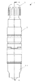
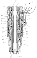
図1は、本発明のプラズマ溶接トーチの外観図であり、図2は、図1のA−A線に沿う断面図であり、図3は、図2のH−H線に沿う断面図であって、図2に示すプラズマ溶接トーチを先端部側から見て軸心方向に対して90度右へ回転させたときの断面図であり、図4は、図2の部分拡大図であり、図5は、図3の部分拡大図であり、図6(A)は、図2のB−B線に沿う断面図であり、図6(B)は、図2のC−C線に沿う断面図であり、図6(C)は、図2のD−D線に沿う断面図であり、図6(D)は、図2のE−E線に沿う断面図であり、図7(A)は、図3のF−F線に沿う断面図であり、図7(B)は、図3のG−G線に沿う断面図である。 1 is an external view of the plasma welding torch of the present invention, FIG. 2 is a cross-sectional view taken along the line AA in FIG. 1, and FIG. 3 is a cross-sectional view taken along the line HH in FIG. FIG. 4 is a cross-sectional view when the plasma welding torch shown in FIG. 2 is rotated 90 degrees to the right with respect to the axial direction when viewed from the front end side, and FIG. 5 is a partially enlarged view of FIG. 3, FIG. 6 (A) is a cross-sectional view taken along line BB in FIG. 2, and FIG. 6 (B) is taken along line CC in FIG. FIG. 6C is a cross-sectional view taken along line DD in FIG. 2, FIG. 6D is a cross-sectional view taken along line EE in FIG. 2, and FIG. FIG. 7A is a cross-sectional view taken along line FF in FIG. 3, and FIG. 7B is a cross-sectional view taken along line GG in FIG.
図1〜7において、プラズマ溶接トーチ1のトーチボディ2の軸芯部に、通常、タングステンで形成されている電極3が設けられている。この電極3はコレット4に挿通されて、コレット4がコレットボディ5に挿入されて、コレットボディ5が、絶縁ブッシュ6を介してトーチボディ2に取付けられている。キャップ7をねじ込むことによって、電極3の位置がコレットボディ5に対して固定される。
1 to 7, an
プラズマノズル8は筒状で導電性があり、プラズマノズル8の基端部が、トーチボディ2の先端部に取り付けられている。プラズマノズル8の先端部に、プラズマ噴出孔8aが形成されている。電極3の先端が、センタリングストーン9の先端部からプラズマノズル8内に突き出されるように、電極3がセンタリングストーン9に挿入されている。センタリングストーン9がプラズマノズル8に挿入されている。センタリングストーン9には、電極3の軸ずれを防ぐ機能が有り、さらにセンタリングストーン9は筒状で電気絶縁性が有るので、電極3とプラズマノズル8との間以外の箇所でパイロットアークが点弧することを防いでいる。センタリングストーン9には、プラズマガスが噴出されるプラズマガス用孔が軸方向に形成されている場合がある。プラズマノズル8の内部で、電極3の周囲にプラズマガスが供給されて、プラズマガスがプラズマ噴出孔8aから噴出される。
The
トーチボディ2の先端部で、プラズマノズル8の周囲にノズルホルダ10を介してシールドガスカップ11が設けられている。シールドガスカップ11は耐熱性が有り、プラズマノズル8の先端部を取囲み、トーチボディ2にねじ止めされている。冷却水流路が、トーチボディ2又はプラズマノズル8内に設けられている。シールドガス流路が、トーチボディ2又はノズルホルダ10内に設けられている。シールドガス流路は、電極3に対して、冷却水流路の外側に位置している。
At the tip of the
図4及び図5に実線の矢印で示す冷却水流路Wは、第1の冷却水流路W1乃至第7の冷却水流路W7を含む。第1の冷却水流路W1は、トーチボディ2内で、電極3の軸心方向に設けられている。第2の冷却水流路W2は、その基端部が、第1の冷却水流路W1の先端部に連通されていて、図6(D)のE−E線に沿う断面図に示すように、第2の冷却水流路W2は、電極3の半径方向に設けられている。第3の冷却水流路W3は、その基端部が第2の冷却水流路W2に連通されて、図6(C)のD−D線に沿う断面図及び図6(B)のC−C線に沿う断面図に示すように、プラズマノズル8内で、第3の冷却水流路W3は、電極3の軸心方向に設けられている。また、第3の冷却水流路W3と電極3との距離が、第1の冷却水流路W1と電極3との距離よりも短い位置となるように、第3の冷却水流路W3が設けられている。第4の冷却水流路W4は、その基端部が第3の冷却水流路W3の先端部に連通されて、図6(A)のB−B線に沿う断面図に示すように、プラズマノズル8の先端部内で、第4の冷却水流路W4は、電極3の周囲にリング状に設けられている。
The cooling water flow path W indicated by the solid line arrows in FIGS. 4 and 5 includes the first cooling water flow path W1 to the seventh cooling water flow path W7. The first cooling water flow path W <b> 1 is provided in the axial direction of the
第5の冷却水流路W5は、その基端部が第4の冷却水流路W4に連通されて、図6(C)のD−D線に沿う断面図に示すように、プラズマノズル8内で、第5の冷却水流路W5は、電極3の軸心方向に設けられている。第6の冷却水流路W6は、その基端部が第5の冷却水流路W5の先端部に連通されて、図6(D)のE−E線に沿う断面図に示すように、第6の冷却水流路W6は、電極3の半径方向に設けられている。第7の冷却水流路W7は、その基端部が第6の冷却水流路W6に連通されて、トーチボディ2内で、電極3の軸心方向に設けられている。また、第7の冷却水流路W7と電極3との距離が、第5の冷却水流路W5と電極3との距離よりも長い位置となるように、第7の冷却水流路W7が設けられている。即ち、第5の冷却水流路W5と電極3との距離が、第7の冷却水流路W7と電極3との距離よりも短い位置となるように、第5の冷却水流路W5が設けられている。
The fifth cooling water flow path W5 is connected to the fourth cooling water flow path W4 at its base end, and as shown in the cross-sectional view along the line DD in FIG. The fifth cooling water flow path W5 is provided in the axial direction of the
図4及び図5に破線の矢印で示すシールドガス流路Gは、第1のシールドガス流路G1乃至第3のシールドガス流路G3から成る。第1のシールドガス流路G1は、トーチボディ2内で、電極3の軸心方向に設けられている。図6(D)のE−E線に沿う断面図に示すように、第1のシールドガス流路G1は、複数設けられても良い。第2のシールドガス流路G2は、その基端部が第1のシールドガス流路G1の先端部に連通されて、トーチボディ2内で電極3の半径方向で、電極3の周囲にリング状に設けられている。第3のシールドガス流路G3は、その基端部が第2のシールドガス流路G2に連通されて、ノズルホルダ10内で、電極3の軸心方向に設けられている。
The shield gas flow path G indicated by the dashed arrows in FIGS. 4 and 5 includes the first shield gas flow path G1 to the third shield gas flow path G3. The first shield gas flow path G <b> 1 is provided in the axial direction of the
図6(C)のD−D線に沿う断面図に示すように、ノズルホルダ10には、複数の第3のシールドガス流路G3が電極3の半径方向に形成されている。図6(C)においては、8個の第3のシールドガス流路G3が形成されている場合を示している。図6(B)のC−C線に沿う断面図に示すように、ノズルホルダ10の先端部には、複数の第3のシールドガス流路G3に連通した複数のシールドガス噴出孔10aがそれぞれ形成されている。図6(B)においては、8個のシールドガス噴出孔10aが形成されている場合を示している。
As shown in the cross-sectional view along the line D-D in FIG. 6C, the
第2のシールドガス流路G2は、第2の冷却水流路W2よりも電極3の先端部側に位置している。電極3の先端部側から見て、第2のシールドガス流路G2が第2の冷却水流路W2の一部と重なる位置に設けられている。
The second shield gas channel G2 is located closer to the tip of the
以下、動作を説明する。冷却水が、冷却水循環装置(図示を省略)からコンジットケーブル(図示を省略)によって、溶接電源(図示を省略)を中継してプラズマ溶接トーチ1に供給される。また、プラズマガス及びシールドガスが、プラズマガスボンベ(図示を省略)及びシールドガスボンベ(図示を省略)からコンジットケーブル(図示を省略)によって溶接電源(図示を省略)を中継してプラズマ溶接トーチ1にそれぞれ供給される。陰極とされた電極3が放電されて、主プラズマアークが発生する。トーチボディ2の基端部から供給されたプラズマガスが、電極3の周囲に供給されて、プラズマガスがプラズマノズル8のプラズマ噴出孔8aから噴出される。トーチボディ2の基端部から供給された冷却水が、第1の冷却水流路W1乃至第7の冷却水流路W7に供給されて、プラズマノズル8が冷却される。第7の冷却水流路W7を通過した冷却水は、コンジットケーブル(図示を省略)によって、溶接電源(図示を省略)を中継して、冷却水循環装置(図示を省略)に返還される。
The operation will be described below. Cooling water is supplied to the
プラズマガスは、水冷されたプラズマノズル8とプラズマガスのガス流とによって拘束されることによって、集中性の良い高温プラズマ流が発生され、この保有エネルギを利用してプラズマ溶接が行われる。トーチボディ2に供給されたシールドガスが、第1のシールドガス流路G1乃至第3のシールドガス流路G3を経由して供給される。そして、シールドガスが、ノズルホルダ10の先端部に形成された複数のシールドガス噴出孔10aから噴出されて、シールドガスカップ11の先端部から噴出される。シールドガスがプラズマアーク、溶融池及びその周辺を大気から遮蔽する。
The plasma gas is constrained by the water-cooled
この結果、本発明のプラズマ溶接トーチ1は、第1の冷却水流路W1乃至第7の冷却水流路W7と、第1のシールドガス流路G1乃至第3のシールドガス流路G3とのそれぞれの流路が、プラズマ溶接トーチ1の先端部方向に階段状に、電極3に近付くように設けられている。即ち、第1の冷却水流路W1乃至第7の冷却水流路W7と第1のシールドガス流路G1乃至第3のシールドガス流路G3とのそれぞれの流路において、プラズマ溶接トーチ1の基端部側の流路(即ち、第1の冷却水流路W1と第1のシールドガス流路G1)と電極3との距離よりも、プラズマ溶接トーチ1の先端部側の流路(即ち、第3の冷却水流路W3と第3のシールドガス流路G3)と電極3との距離の方が、短く設けられている。そのために、プラズマ溶接トーチ1の先端部の直径を小さくすることができ、プラズマ溶接トーチ1の小型化を図ることができる。
As a result, the
たとえば、本発明のプラズマ溶接トーチ1は、定格電流が350[A]で使用率が70[%]の場合、プラズマ溶接トーチ1の先端部の直径を、従来のプラズマ溶接トーチと比較して、約20[%]減少させることができた。
For example, in the
よって、本発明のプラズマ溶接トーチ1は、被加工物に対して干渉することを低減することができ、被加工物の狭わい部へプラズマ溶接トーチ1を接近させることが容易になるので、プラズマ溶接トーチ1の操作性を大幅に向上させることができる。
Therefore, the
上述した本発明のプラズマ溶接トーチ1の第2の冷却水流路W2及び第2のシールドガス流路G2は、電極3に対して半径方向に設けているが、この代わりに、電極3の先端部方向へ傾斜するように設けても良い。
The second cooling water channel W2 and the second shield gas channel G2 of the
1 プラズマ溶接トーチ
2 トーチボディ
3 電極
4 コレット
5 コレットボディ
6 絶縁ブッシュ
7 キャップ
8 プラズマノズル
8a プラズマ噴出孔
9 センタリングストーン
10 ノズルホルダ
10a シールドガス噴出孔
11 シールドガスカップ
G シールドガス流路
G1 第1のシールドガス流路
G2 第2のシールドガス流路
G3 第3のシールドガス流路
W 冷却水流路
W1 第1の冷却水流路
W2 第2の冷却水流路
W3 第3の冷却水流路
W4 第4の冷却水流路
W5 第5の冷却水流路
W6 第6の冷却水流路
W7 第7の冷却水流路
DESCRIPTION OF
Claims (5)
前記トーチボディの軸心部に設けられた電極と、
前記電極の先端部側の周囲に設けられて、内部にプラズマガスが供給されるプラズマノズルと、
前記トーチボディの先端部で、前記プラズマノズルの周囲にノズルホルダを介して設けられたシールドガスカップと、
前記トーチボディ又は前記プラズマノズル内に設けられた冷却水流路と、
前記冷却水流路の外側で、前記トーチボディ又は前記ノズルホルダ内に設けられたシールドガス流路とを備え、
前記冷却水流路が、前記トーチボディ内で、前記電極の軸心方向に設けられた第1の冷却水流路と、
基端部が前記第1の冷却水流路の先端部に連通されて、前記電極の半径方向に設けられた第2の冷却水流路と、
基端部が前記第2の冷却水流路に連通されて、前記プラズマノズル内で、前記電極との距離が、前記第1の冷却水流路と前記電極との距離よりも短い位置で、前記電極の軸心方向に設けられた第3の冷却水流路と、
基端部が前記第3の冷却水流路の先端部に連通されて、前記プラズマノズルの先端部内に設けられた第4の冷却水流路と、
基端部が前記第4の冷却水流路に連通されて、前記プラズマノズル内で、前記電極の軸心方向に設けられた第5の冷却水流路と、
基端部が前記第5の冷却水流路の先端部に連通されて、前記電極の半径方向に設けられた第6の冷却水流路と、
基端部が前記第6の冷却水流路に連通されて、前記トーチボディ内で、前記電極との距離が、前記第5の冷却水流路と前記電極との距離よりも長い位置に設けられた第7の冷却水流路とを有し、
前記冷却水が前記第1の冷却水流路乃至前記第7の冷却水流路に供給されることを特徴とするプラズマ溶接トーチ。 Torch body,
An electrode provided at the axial center of the torch body;
A plasma nozzle provided around the tip of the electrode and supplied with plasma gas;
A shield gas cup provided through a nozzle holder around the plasma nozzle at the tip of the torch body;
A cooling water flow path provided in the torch body or the plasma nozzle;
A shield gas flow path provided inside the torch body or the nozzle holder outside the cooling water flow path,
A first cooling water passage provided in the axial direction of the electrode in the torch body;
A second cooling water flow path provided in a radial direction of the electrode, with a base end portion communicating with a distal end portion of the first cooling water flow path;
A base end portion is communicated with the second cooling water flow path, and the electrode is located in the plasma nozzle at a position where the distance from the electrode is shorter than the distance between the first cooling water flow path and the electrode. A third cooling water flow path provided in the axial direction of
A fourth cooling water flow path provided in a distal end portion of the plasma nozzle, with a base end portion communicating with a distal end portion of the third cooling water flow path;
A base end portion communicating with the fourth cooling water flow path, and a fifth cooling water flow path provided in the axial direction of the electrode in the plasma nozzle;
A base end portion communicating with a tip end portion of the fifth cooling water flow path, and a sixth cooling water flow path provided in a radial direction of the electrode;
A base end portion is communicated with the sixth cooling water flow path, and the distance from the electrode is longer than the distance between the fifth cooling water flow path and the electrode in the torch body. A seventh cooling water flow path,
The plasma welding torch characterized in that the cooling water is supplied to the first cooling water channel to the seventh cooling water channel.
基端部が前記第1のシールドガス流路の先端部に連通されて、前記電極の半径方向に設けられた第2のシールドガス流路と、
基端部が前記第2のシールドガス流路に連通されて、前記ノズルホルダ内で、前記電極との距離が、前記第1のシールドガス流路と前記電極との距離よりも短い位置で、前記電極の軸心方向に設けられた第3のシールドガス流路とを有し、
前記シールドガスが、前記第1のシールドガス流路乃至前記第3のシールドガス流路に供給されることを特徴とするプラズマ溶接トーチ。 The shield gas channel according to claim 1, wherein the shield gas channel provided in the axial direction of the electrode in the torch body;
A second shield gas flow path provided in a radial direction of the electrode, with a base end portion communicating with a distal end portion of the first shield gas flow path;
The base end is communicated with the second shield gas flow path, and the distance between the electrode and the electrode within the nozzle holder is shorter than the distance between the first shield gas flow path and the electrode. A third shield gas flow path provided in the axial direction of the electrode,
The plasma welding torch characterized in that the shield gas is supplied to the first shield gas channel to the third shield gas channel.
Priority Applications (1)
| Application Number | Priority Date | Filing Date | Title |
|---|---|---|---|
| JP2014144029A JP2016019986A (en) | 2014-07-14 | 2014-07-14 | Plasma welding torch |
Applications Claiming Priority (1)
| Application Number | Priority Date | Filing Date | Title |
|---|---|---|---|
| JP2014144029A JP2016019986A (en) | 2014-07-14 | 2014-07-14 | Plasma welding torch |
Publications (1)
| Publication Number | Publication Date |
|---|---|
| JP2016019986A true JP2016019986A (en) | 2016-02-04 |
Family
ID=55265196
Family Applications (1)
| Application Number | Title | Priority Date | Filing Date |
|---|---|---|---|
| JP2014144029A Pending JP2016019986A (en) | 2014-07-14 | 2014-07-14 | Plasma welding torch |
Country Status (1)
| Country | Link |
|---|---|
| JP (1) | JP2016019986A (en) |
Cited By (1)
| Publication number | Priority date | Publication date | Assignee | Title |
|---|---|---|---|---|
| CN108145294A (en) * | 2016-12-02 | 2018-06-12 | 唐山开元焊接自动化技术研究所有限公司 | A kind of high powered plasma welding gun |
Citations (4)
| Publication number | Priority date | Publication date | Assignee | Title |
|---|---|---|---|---|
| JPS54184326U (en) * | 1978-06-19 | 1979-12-27 | ||
| JPH0220667A (en) * | 1988-07-06 | 1990-01-24 | Origin Electric Co Ltd | Plasma torch |
| JPH0287564U (en) * | 1988-12-24 | 1990-07-11 | ||
| JPH08132244A (en) * | 1994-11-07 | 1996-05-28 | Daihen Corp | Torch and method for plasma arc cutting |
-
2014
- 2014-07-14 JP JP2014144029A patent/JP2016019986A/en active Pending
Patent Citations (4)
| Publication number | Priority date | Publication date | Assignee | Title |
|---|---|---|---|---|
| JPS54184326U (en) * | 1978-06-19 | 1979-12-27 | ||
| JPH0220667A (en) * | 1988-07-06 | 1990-01-24 | Origin Electric Co Ltd | Plasma torch |
| JPH0287564U (en) * | 1988-12-24 | 1990-07-11 | ||
| JPH08132244A (en) * | 1994-11-07 | 1996-05-28 | Daihen Corp | Torch and method for plasma arc cutting |
Cited By (2)
| Publication number | Priority date | Publication date | Assignee | Title |
|---|---|---|---|---|
| CN108145294A (en) * | 2016-12-02 | 2018-06-12 | 唐山开元焊接自动化技术研究所有限公司 | A kind of high powered plasma welding gun |
| CN108145294B (en) * | 2016-12-02 | 2023-12-08 | 唐山开元焊接自动化技术研究所有限公司 | High-power plasma welding gun |
Similar Documents
| Publication | Publication Date | Title |
|---|---|---|
| RU2610138C2 (en) | Composite consumable components of torch for welding with plasma arc consumable components torch for welding plasma arc | |
| US9131596B2 (en) | Plasma cutting tip with advanced cooling passageways | |
| JP6139022B2 (en) | Gas welding torch with diffuser | |
| RU2556875C2 (en) | Electrode for plasma torch with new assembly process and better heat transfer | |
| JP5191715B2 (en) | Forced pressurized power supply torch | |
| US9730307B2 (en) | Multi-component electrode for a plasma cutting torch and torch including the same | |
| US8362387B2 (en) | Electrode for plasma arc torch and related plasma arc torch | |
| US9370088B2 (en) | Method and apparatus for recycling shield gas in a plasma arc torch | |
| JP2016019986A (en) | Plasma welding torch | |
| JP2019533077A (en) | Plasma spraying equipment | |
| JP7090074B2 (en) | Applications for nozzle protection caps, plasma arc torches with nozzle protection caps, and plasma arc torches | |
| JP6612626B2 (en) | Plasma welding torch | |
| JP2005288446A (en) | Plasma torch | |
| US10582606B2 (en) | Nozzle for a plasma arc torch | |
| JP6084890B2 (en) | Consumable electrode gas shield arc welding torch | |
| JP3714517B2 (en) | Plasma torch, plasma torch electrode and method for manufacturing the same | |
| CN114430705B (en) | Arc or plasma torch or plasma cutting torch comprising an electrode, method for producing the electrode and method for plasma cutting | |
| JP2017119297A (en) | Plasma arc torch | |
| JP7644730B2 (en) | Plasma Welding Torch | |
| JP2007128677A (en) | Plasma torch | |
| JP7474676B2 (en) | Plasma torch and center pipe for plasma torch | |
| JP2010167443A (en) | Welding torch | |
| JP2005324205A (en) | Plasma torch and guide | |
| JP6542628B2 (en) | Plasma welding torch | |
| JP2012101238A (en) | Torch body and welding torch |
Legal Events
| Date | Code | Title | Description |
|---|---|---|---|
| A621 | Written request for application examination |
Free format text: JAPANESE INTERMEDIATE CODE: A621 Effective date: 20170510 |
|
| A131 | Notification of reasons for refusal |
Free format text: JAPANESE INTERMEDIATE CODE: A131 Effective date: 20180125 |
|
| A977 | Report on retrieval |
Free format text: JAPANESE INTERMEDIATE CODE: A971007 Effective date: 20180131 |
|
| A521 | Request for written amendment filed |
Free format text: JAPANESE INTERMEDIATE CODE: A523 Effective date: 20180313 |
|
| A02 | Decision of refusal |
Free format text: JAPANESE INTERMEDIATE CODE: A02 Effective date: 20180705 |