JP2016018317A - Operation management device - Google Patents
Operation management device Download PDFInfo
- Publication number
- JP2016018317A JP2016018317A JP2014139695A JP2014139695A JP2016018317A JP 2016018317 A JP2016018317 A JP 2016018317A JP 2014139695 A JP2014139695 A JP 2014139695A JP 2014139695 A JP2014139695 A JP 2014139695A JP 2016018317 A JP2016018317 A JP 2016018317A
- Authority
- JP
- Japan
- Prior art keywords
- vehicle
- unit
- time
- actual
- vehicles
- Prior art date
- Legal status (The legal status is an assumption and is not a legal conclusion. Google has not performed a legal analysis and makes no representation as to the accuracy of the status listed.)
- Pending
Links
Images


Landscapes
- Traffic Control Systems (AREA)
- Management, Administration, Business Operations System, And Electronic Commerce (AREA)
- Time Recorders, Dirve Recorders, Access Control (AREA)
Abstract
Description
本発明は、運行管理業務に用いられる運行管理装置に関するものである。 The present invention relates to an operation management device used for operation management work.
特許文献1には、車両の運行業務を伴う複数の支社や営業所に設置され、運行効率を蓄積データに基づいて定量化する処理、連続運転時間と休憩時間との時間軸上の配列をもとに将来の運行計画を作成する処理、定期点検の終期が一定期間内となる期限データを自動抽出する処理を選択的に実行する運行管理システムが開示されている。
しかしながら、特許文献1に開示の運行管理システムは、業務に用いられる車両の運行に関する詳細な改善点を抽出しにくいという問題を有していた。詳しくは、以下の通りである。
However, the operation management system disclosed in
特許文献1に開示の処理装置では、車両の運行効率として稼働率や実車率が計算されて、運転効率の向上策の立案に供されるが、稼働率や実車率では、どの時間帯に車両が稼働しているか、どの時間帯に空車となっているかといったことまでは判らず、詳細な改善点を抽出しにくい。また、稼働率や実車率では、低燃費走行(いわゆるエコドライブ)の程度までは判らず、詳細な改善点を抽出しにくい。
In the processing apparatus disclosed in
他にも、特許文献1に開示の処理装置では、連続運転時間と休憩時間との時間軸上の配列については記載があるが、連続運転時間と休憩時間との時間軸上の配列だけでは、ドライバの疲労蓄積度合いは判りづらく、詳細な改善点を抽出しにくい。
In addition, in the processing apparatus disclosed in
また、特許文献1に開示の処理装置では、定期点検の終期が一定期間内となる期限データを自動抽出することで、点検の対象となる車両のリストを出力するが、どの部分の点検が必要かは判らず、詳細な改善点が抽出しにくい。
Moreover, in the processing apparatus disclosed in
本発明は、上記従来の問題点に鑑みなされたものであって、その目的は、業務に用いられる複数の車両の運行に関して、より詳細な改善点を抽出しやすくすることを可能にする運行管理装置を提供することにある。 The present invention has been made in view of the above-described conventional problems, and its purpose is operation management that makes it easier to extract more detailed improvements regarding the operation of a plurality of vehicles used in business. To provide an apparatus.
本発明の運行管理装置は、輸送業務に用いられる複数の車両の運行を管理する運行管理システム(100)で用いられ、この複数の車両の運行データを取得する運行データ取得部(11)を備える運行管理装置であって、運行データには、車両の運行開始及び運行終了の時刻、並びに車両の実車走行の開始及び終了時刻と空車走行の開始及び終了時刻とを含み、運行データ取得部で取得した車両の運行開始及び運行終了の時刻から、時間帯ごとの車両の稼働の有無を特定するとともに、運行データ取得部で取得した車両の実車走行の開始及び終了時刻と空車走行の開始及び終了時刻とから、時間帯ごとの車両が実車走行か空車走行かの実車/空車状態も特定する運行状態特定部(12)と、運行状態特定部で特定した時間帯ごとの複数の車両の稼働の有無及び実車/空車状態から、時間帯ごとの各車両の稼働の有無と各車両の実車/空車状態とを示した表を作成するレポート作成部(13)と、レポート作成部で作成した、時間帯ごとの各車両の稼働の有無と各車両の実車/空車状態とを示した表を出力するレポート出力部(14)とを備えることを特徴としている。 The operation management device of the present invention is used in an operation management system (100) that manages the operation of a plurality of vehicles used in transportation work, and includes an operation data acquisition unit (11) that acquires operation data of the plurality of vehicles. It is an operation management device, and the operation data includes the start and end times of the vehicle operation, the start and end times of the actual vehicle travel, and the start and end times of the empty vehicle travel, and is acquired by the operation data acquisition unit. The start and end times of the actual vehicle travel and the start and end times of the empty vehicle travel obtained by the operation data acquisition unit are specified from the operation start time and the operation end time of the completed vehicle. The operation state specifying unit (12) for specifying the actual vehicle / empty state whether the vehicle for each time zone is a real vehicle run or an empty vehicle run, and a plurality of vehicles for each time zone specified by the operation state specification unit Created by the report creation unit (13) and a report creation unit that creates a table showing the availability of each vehicle and the actual vehicle / empty status of each vehicle based on availability and actual vehicle / empty status And a report output unit (14) for outputting a table indicating whether or not each vehicle is operating for each time period and the actual / empty state of each vehicle.
これによれば、輸送業務に用いられる複数の車両について、時間帯ごとの各車両の稼働の有無と各車両の実車/空車状態とを示した表を作成して出力するので、ユーザがこの表を見れば、どの時間帯にどの車両が稼働しているか、どの時間帯にどの車両が空車走行となっているかが判りやすい。よって、稼働していない車両の多い時間帯や空車走行が続く時間帯といった、運行計画の見直し点を詳細に抽出することが可能になる。その結果、業務に用いられる複数の車両の運行に関して、より詳細な改善点を抽出しやすくすることを可能にする。 According to this, for a plurality of vehicles used for transportation work, a table indicating whether each vehicle is operating for each time zone and the actual / empty state of each vehicle is created and output. It is easy to see which vehicle is operating in which time zone and which vehicle is idle in which time zone. Therefore, it becomes possible to extract in detail the review points of the operation plan, such as the time zone in which there are many vehicles that are not in operation and the time zone in which the empty vehicle travels. As a result, it is possible to easily extract more detailed improvements regarding the operation of a plurality of vehicles used in business.
また、本発明の他の運行管理装置は、業務に用いられる複数の車両の運行を管理する運行管理システムで用いられ、この複数の車両の運行データを取得する運行データ取得部(11)を備える運行管理装置であって、運行データには、車両の走行用エネルギーの消費効率と、その消費効率に影響を与える、走行中の運転操作によって変化する車両の状態値とを含み、運行データ取得部で取得した複数の車両の走行用エネルギーの消費効率と、状態値とから、複数の車両別に、走行用エネルギーの消費効率と、その消費効率に影響を与える状態値の度数分布とを関連付けて示した表を作成するレポート作成部(13)と、レポート作成部で作成した、複数の車両別に走行用エネルギーの消費効率とその消費効率に影響を与える状態値の度数分布とを関連付けて示した表を出力するレポート出力部(14)とを備えることを特徴としている。
Moreover, the other operation management apparatus of this invention is used with the operation management system which manages operation | movement of the some vehicle used for work, and is provided with the operation data acquisition part (11) which acquires operation data of this some vehicle. It is an operation management device, and the operation data includes an operation efficiency of the vehicle's energy for travel and a state value of the vehicle that changes the driving operation during travel that affects the efficiency of the operation. The energy consumption efficiency of multiple vehicles and the state values acquired in
これによれば、業務に用いられる複数の車両について、走行用エネルギーの消費効率と、その消費効率に影響を与える、走行中の運転操作によって変化する状態値の度数分布とを関連付けて示した表を作成して出力するので、ユーザがこの表を見れば、走行用エネルギーの消費効率が悪い場合の状態値の度数分布が判りやすい。よって、走行用エネルギーの消費効率が悪くなる場合の状態値を抽出することが可能になる。また、状態値は、走行中の運転操作によって変化するものであるので、走行用エネルギーの消費効率が悪くなる場合の状態値を抽出することで、走行用エネルギーの消費効率を悪くしている走行中の運転操作を抽出することが可能になり、改善すべき運転操作を詳細に抽出することが可能になる。その結果、業務に用いられる複数の車両の運行に関して、より詳細な改善点を抽出しやすくすることを可能にする。 According to this, for a plurality of vehicles used for business, a table showing the consumption efficiency of energy for traveling and the frequency distribution of state values that change according to the driving operation during traveling that affect the consumption efficiency. Therefore, if the user looks at this table, the frequency distribution of the state values in the case where the energy consumption efficiency for traveling is poor can be easily understood. Therefore, it becomes possible to extract the state value when the consumption efficiency of the traveling energy is deteriorated. In addition, since the state value changes depending on the driving operation during traveling, by extracting the state value when the traveling energy consumption efficiency deteriorates, the traveling whose traveling energy consumption efficiency is deteriorated It is possible to extract the driving operation in the middle, and it is possible to extract the driving operation to be improved in detail. As a result, it is possible to easily extract more detailed improvements regarding the operation of a plurality of vehicles used in business.
また、本発明の更なる他の運行管理装置は、業務に用いられる複数の車両の運行を管理する運行管理システムで用いられ、この複数の車両の運行データを取得する運行データ取得部(11)を備える運行管理装置であって、運行データには、車両の走行を特定できる車両の状態値の時系列データを含み、運行データ取得部で取得した車両の走行を特定できる車両の状態値の時系列データから、時間帯ごとの車両の走行の有無を特定する運行状態特定部(12)と、運行データ取得部で取得した車両の走行を特定できる車両の状態値の時系列データから、所定の条件を超える車両の長時間運転を特定する長時間運転特定部(15)と、運行状態特定部で特定した時間帯ごとの車両の走行の有無と、長時間運転特定部で特定した長時間運転とから、時間帯ごとの各車両の走行の有無と長時間運転の有無とを示した表を作成するレポート作成部(13)と、レポート作成部で作成した、時間帯ごとの各車両の所定時間以上の運転の有無と長時間運転の有無とを示した表を出力するレポート出力部(14)とを備えることを特徴としている。 Further, another operation management device of the present invention is used in an operation management system that manages the operation of a plurality of vehicles used in business, and an operation data acquisition unit (11) that acquires operation data of the plurality of vehicles. The operation data includes time-series data of vehicle state values that can specify vehicle travel, and vehicle state values that can specify vehicle travel acquired by the operation data acquisition unit. From the series data, the operation state specifying unit (12) that specifies whether or not the vehicle is traveling for each time zone, and the time series data of the vehicle state value that can specify the vehicle travel acquired by the operation data acquisition unit, Long-time driving specifying unit (15) for specifying long-time driving of vehicles exceeding the conditions, presence / absence of vehicle driving for each time zone specified by the operation state specifying unit, and long-time driving specified by the long-time driving specifying unit And from A report creation unit (13) that creates a table indicating whether or not each vehicle travels for each time zone and whether or not the vehicle is operated for a long time, and a predetermined time or more of each vehicle created by the report creation unit for each time zone A report output unit (14) that outputs a table indicating whether or not the vehicle is operated and whether or not the vehicle is operated for a long time is provided.
これによれば、業務に用いられる複数の車両について、時間帯ごとの各車両の走行の有無と各車両の所定の条件を超える長時間運転の有無とを示した表を作成して出力するので、ユーザがこの表を見れば、どの車両がどの程度の長時間運転をしているかが判りやすい。どの車両がどの程度の長時間運転をしているかが判ると、ドライバの疲労蓄積度合いが判りやすくなり、運行計画の見直し点を詳細に抽出することが可能になる。その結果、業務に用いられる複数の車両の運行に関して、より詳細な改善点を抽出しやすくすることを可能にする。 According to this, for a plurality of vehicles used for work, a table showing whether or not each vehicle travels for each time zone and whether or not each vehicle runs for a long time exceeding a predetermined condition is generated and output. If the user looks at this table, it is easy to see which vehicle is driving for how long. Knowing which vehicle is driving for a long time makes it easier to understand the driver's degree of fatigue accumulation, and makes it possible to extract the details of the review of the operation plan. As a result, it is possible to easily extract more detailed improvements regarding the operation of a plurality of vehicles used in business.
また、本発明の更なる他の運行管理装置は、業務に用いられる複数の車両の運行を管理する運行管理システムで用いられ、この複数の車両の運行データを取得する運行データ取得部(11)を備える運行管理装置であって、運行データには、車両の消耗部品の使用頻度を示す情報を含み、運行データ取得部で取得した車両の消耗部品の使用頻度を示す情報から、複数の車両別にその車両の消耗部品の使用頻度を示した表を作成するレポート作成部(13)と、レポート作成部で作成した、複数の車両別にその車両の消耗部品の使用頻度を示した表を出力するレポート出力部(14)とを備えることを特徴としている。 Further, another operation management device of the present invention is used in an operation management system that manages the operation of a plurality of vehicles used in business, and an operation data acquisition unit (11) that acquires operation data of the plurality of vehicles. The operation data includes information indicating the use frequency of the consumable parts of the vehicle, and the information indicating the use frequency of the consumable parts of the vehicle acquired by the operation data acquisition unit, for each of the plurality of vehicles. A report creation unit (13) that creates a table showing the frequency of use of consumable parts of the vehicle, and a report that is created by the report creation unit and that outputs a table showing the frequency of use of consumable parts of the vehicle for each of a plurality of vehicles. And an output unit (14).
これによれば、業務に用いられる複数の車両について、複数の車両別にその車両の消耗部品の使用頻度を示した表を作成して出力するので、ユーザがこの表を見れば、どの車両のどの消耗部品の使用頻度が高くなっているかが判りやすい。よって、要点検箇所を詳細に抽出することが可能になる。その結果、業務に用いられる複数の車両の運行に関して、より詳細な改善点を抽出しやすくすることを可能にする。 According to this, for a plurality of vehicles used for business, a table showing the usage frequency of consumable parts of the vehicle is created and output for each of the plurality of vehicles. It is easy to see if the frequency of use of consumable parts is high. Therefore, it becomes possible to extract the point requiring inspection in detail. As a result, it is possible to easily extract more detailed improvements regarding the operation of a plurality of vehicles used in business.
以下、本発明の実施形態について図面を用いて説明する。 Hereinafter, embodiments of the present invention will be described with reference to the drawings.
(実施形態1)
<運行管理システム100の概略構成>
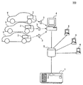
運行管理システム100は、客や貨物の輸送業務に用いられる車両の運行管理業務に用いるものであり、図1に示すように、データ分析サーバ1、複数の車両Vの各々に搭載された運行記録装置2、複数の運行記録装置2の各々で用いられるSDカード(SD Memory Card)3、複数のPC(Personal Computer)4、及びファイルサーバ5を含む。
(Embodiment 1)
<Schematic configuration of the
The
運行記録装置2は、運行管理システム100で管理される車両Vに搭載され、車両Vの運行に関するデータ(以下、運行データ)を、自装置のSDカードスロットに挿入中のSDカード3に記録する。運行データについては後に詳述する。
The
SDカード3は、運行記録装置2によって運行データが次記録される記録媒体であって、運行記録装置2のSDカードスロットから取り出され、PC4のSDカードスロットにも挿入される。
The
PC4は、運行管理システム100を利用する事業者のPCであって、例えばユーザの操作に従って、PC4のSDカードスロットに挿入されたSDカード3から、SDカード3に記録された運行データを読み出す。PC4は、SDカード3から読み出した運行データを、ネットワークを介してファイルサーバ5に送信する。
The
例えば、PC4は各事業所に設けられており、自らが設けられている事業所で用いられる車両Vについての運行データを読みだし、運行データをファイルサーバ5に送信する際には、自らが設けられている事業所を特定できる識別子(以下、事業所コード)を運行データに付与してファイルサーバ5に送信する構成とすればよい。
For example, the
また、PC4は、ファイルサーバ5に送信した運行データについて、後述するレポートがデータ分析サーバ1からファイルサーバ5に出力された場合に、ファイルサーバ5にアクセスしてこのレポートをディスプレイに表示したりする。
The
ファイルサーバ5は、ネットワーク上でファイルを共有するために設置されるサーバであって、各PC4からネットワークを介して送信されてくる運行データを収集して管理する。例えば、ファイルサーバ5は、運行データに付与されている事業所コード別に運行データをファイルにまとめ、事業所別のファイル単位で運行データを管理する構成とすればよい。
The
また、ファイルサーバ5は、事業所別のファイル単位で管理している運行データについて、後述するレポートがデータ分析サーバ1から出力された場合に、このレポートのファイルも事業所別に管理する。
Further, the
データ分析サーバ1は、主にマイクロコンピュータとして構成され、いずれも周知のCPU、ROMやRAM等のメモリ、I/O、及びこれらを接続するバスによって構成される。データ分析サーバ1は、ファイルサーバ5に収集された複数の車両Vの運行データを取得し、取得した運行データに基づき、要改善点を抽出するためのレポートを作成して出力するレポート出力関連処理等の各種処理を実行する。このデータ分析サーバ1が、請求項の運行管理装置に相当する。
The
なお、データ分析サーバ1が実行する機能の一部又は全部を、一つ或いは複数のIC等によりハードウェア的に構成してもよい。
Note that some or all of the functions executed by the
<運行データについて>
ここで、運行記録装置2によってSDカード3に記録される運行データについての説明を行う。例えば、運行データには、所定周期(例えば1分など)ごとに記録される車両Vの位置情報、車速、前後加速度(以下、前後G)、エンジン回転数、走行距離、燃費、イグニッション(以下、IG)オン信号、アクセサリー(以下、ACC)信号、ブレーキスイッチ信号の時系列データや、車両Vの運行開始時刻、運行終了時刻、実車/空車切換時刻、高速道路/一般道路切換時刻などがある。また、運行データには、運行データが得られた運行記録装置2を特定するIDが付与されてSDカード3に記録されるものとする。
<About operation data>
Here, the operation data recorded on the
位置情報については、車両Vに搭載された衛星測位システムの受信機を用いて測位した車両Vの位置情報(つまり、緯度/経度)を運行記録装置2が所定周期ごとに取得し、SDカード3に逐次記録する構成とすればよい。
As for the position information, the
車速については、車両Vに搭載された車輪速センサのパルス信号を運行記録装置2が所定周期ごとに取得し、取得したパルス信号から算出した車速をSDカード3に逐次記録する構成とすればよい。なお、車輪速センサのパルス信号をSDカード3に逐次記録する構成としてもよい。
As for the vehicle speed, the
前後Gについては、車両Vに搭載された加速度センサで検出された、車両Vの前後方向にかかる前後Gを運行記録装置2が所定周期ごとに取得し、SDカード3に逐次記録する構成とすればよい。なお、前後Gは、車速を時間微分することで運行記録装置2が算出する構成としてもよい。
For the front and rear G, the
エンジン回転数については、エンジン回転数を検出するエンジン回転数センサで検出されたエンジン回転数を運行記録装置2が所定周期ごとに取得し、SDカード3に逐次記録する構成とすればよい。
As for the engine speed, the
走行距離については、所定周期ごとに車輪速センサのパルス信号から算出した車速を時間積分することで運行記録装置2が算出し、SDカード3に逐次記録する構成とすればよい。また、車輪速センサのパルス信号のカウント値からタイヤ転がり距離を算出することで運行記録装置2が走行距離を算出する構成としてもよい。
The travel distance may be calculated by the
燃費については、燃費計で算出した時間あたりの燃費を運行記録装置2が所定周期ごとに取得し、SDカード3に逐次記録する構成とすればよい。車両Vに燃費計を搭載していない場合には、インジェクターの噴射時間とエンジン回転数とから算出した燃料消費量と走行距離とから、運行記録装置2が燃費を算出する構成としてもよい。燃費は、燃料の単位容量あたりの走行距離であってもよいし、一定距離を走行するのに必要な燃料量であってもよいし、
IGスイッチがオンの場合にハイレベルとなる一方、オフの場合にローレベルとなるIGオン信号や、ACCスイッチがオンの場合にハイレベルとなる一方、オフの場合にローレベルとなるACC信号については、電源ラインから運行記録装置2が所定周期ごとに取得し、SDカード3に逐次記録する構成とすればよい。
Regarding the fuel consumption, the
An IG ON signal that is at a high level when the IG switch is on, and is at a low level when it is off, or an ACC signal that is at a high level when the ACC switch is on, and that is at a low level when it is off May be configured such that the
ブレーキスイッチがオンの場合にハイレベルとなる一方、オフの場合にローレベルとなるブレーキスイッチ信号については、ブレーキスイッチに接続された信号線から運行記録装置2が所定周期ごとに取得し、SDカード3に逐次記録する構成とすればよい。ブレーキスイッチは、ブレーキペダルが操作された場合にオンになるスイッチである。
A brake switch signal that is high when the brake switch is on, and low when it is off, is acquired by the
車両Vの運行開始時刻については、ドライバが車両Vの運行を開始するときに操作する運行開始スイッチの操作を運行記録装置2で検出した時刻を、運行開始時刻として運行記録装置2がSDカード3に記録する構成とすればよい。車両Vの運行終了時刻については、ドライバが車両Vの運行を終了したときに操作する運行終了スイッチの操作を運行記録装置2で検出した時刻を、運行終了時刻として運行記録装置2がSDカード3に記録する構成とすればよい。なお、車両の運行開始時刻と運行終了時刻とは、車両Vの車速から特定してSDカード3に記録する構成としてもよい。
As for the operation start time of the vehicle V, the
実車/空車切換時刻については、車両Vが実車走行と空車走行とのいずれを行っているかドライバが切り換えて入力するための実車/空車切換スイッチの操作を運行記録装置2で検出した時刻を、実車/空車切換時刻として運行記録装置2がSDカード3に記録する構成とすればよい。
As for the actual vehicle / empty vehicle switching time, the time when the
高速道路/一般道路切換時刻については、車両Vが高速道路と一般道路とのいずれを走行しているかドライバが切り換えて入力するための高速道路/一般道路切換スイッチの操作を運行記録装置2で検出した時刻を、高速道路/一般道路切換時刻として運行記録装置2がSDカード3に記録する構成とすればよい。
About the highway / general road switching time, the
なお、車両Vの運行開始時刻、運行終了時刻、実車/空車切換時刻、高速道路/一般道路切換時刻については、日付まで含むものとする。 The operation start time, the operation end time, the actual vehicle / empty vehicle switching time, and the expressway / general road switching time of the vehicle V are assumed to include the date.
<実施形態1のデータ分析サーバ1の詳細構成>
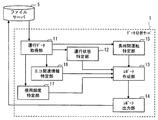
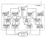
続いて、データ分析サーバ1の詳細構成について説明を行う。図2に示すように、データ分析サーバ1は、運行データ取得部11、運行状態特定部12、レポート作成部13、レポート出力部14、長時間運転特定部15、エコ関連情報特定部16、及び使用頻度特定部17を備えている。
<Detailed Configuration of
Subsequently, a detailed configuration of the
運行データ取得部11は、ファイルサーバ5に格納されている事業所別のファイル単位の運行データを、ネットワークを介して取得する。つまり、運行データ取得部11は、事業所別に、事業所で用いられる複数の車両Vについての運行データを取得する。
The operation
運行状態特定部12、レポート作成部13、レポート出力部14、長時間運転特定部15、エコ関連情報特定部16、及び使用頻度特定部17については、以下で行うレポート出力関連処理の説明において詳述する。
The operation
<稼働/非稼働、実車/空車の状態についてのレポート出力関連処理>
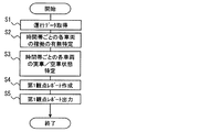
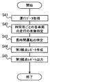
続いて、データ分析サーバ1で行う、車両Vの稼働/非稼働、実車/空車の状態を可視化したレポート(以下、第1観点レポート)を出力するレポート出力関連処理について図3のフローチャートを用いて説明を行う。図3のフローチャートは、一例として、一週間ごとなどの定期的に実施される構成とすればよい。
<Report output related processing for operating / non-operating, actual / empty vehicle status>
Subsequently, a report output related process for outputting a report (hereinafter referred to as a first viewpoint report) that visualizes the operation / non-operation of the vehicle V and the state of the actual vehicle / empty vehicle performed by the
まず、ステップS1では、運行データ取得部11が、事業所別の複数の車両についての運行データを取得する。
First, in step S1, the operation
ステップS2では、S1で取得した運行データのうちの車両Vの運行開始時刻及び運行終了時刻から、運行状態特定部12が、時間帯ごとの各車両Vの稼働の有無を特定する。例えば、時間帯は0時を基準とした1時間単位とし、運行開始時刻や運行終了時刻が属する時間帯については、運行時間が30分以上となる場合は稼働、30分未満となる場合は非稼働とすればよい。
In step S2, the operation
ステップS3では、S1で取得した運行データのうちの車両Vの実車/空車切換時刻から、S2で稼働と特定した時間帯について、運行状態特定部12が、各車両Vが実車走行か空車走行かの実車/空車状態を特定する。実車/空車切換時刻は、デフォルトの状態が空車走行であるものとして、1回目の実車/空車切換時刻から2回目の実車/空車切換時刻までが空車走行、2回目の実車/空車切換時刻から3回目の実車/空車切換時刻までが実車走行といったように特定していくものとする。なお、同じ車両Vの運行データ同士の紐つけは運行データに付与されているIDによって行う構成とすればよい。実車/空車切換時刻が、請求項の実車走行の開始及び終了時刻と空車走行の開始及び終了時刻とに相当する。
In step S3, from the actual vehicle / empty vehicle switching time of the vehicle V in the operational data acquired in S1, the operation
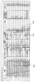
ステップS4では、レポート作成部13が、S2で特定した時間帯ごとの各車両Vの稼働の有無、及びその時間帯ごとのS3で特定した各車両Vの実車/空車状態を示した表としての第1観点レポートを作成する。具体例としては、図4に示すように、各車両Vについての1時間ごとの稼働の有無と実車/空車状態とを時間軸を揃えて並べたガントチャートを作成する構成とすればよい。
In step S4, the
ステップS5では、S4で作成した第1観点レポートをレポート出力部14がネットワークを介してファイルサーバ5に送信する。
In step S5, the
ファイルサーバ5に送信された第1観点レポートは、PC4からファイルサーバ5にアクセスすることで、PC4のディスプレイに表示したりすることができる。ユーザは、PC4のディスプレイに表示される第1観点レポートを確認することで、空車が連続したり(図4のPo1参照)、非稼働の車両Vが多発したり(図4のPo2参照)している非効率な時間帯を容易に抽出することができ、営業活動や運行計画についての要改善点を容易に抽出することが可能になる。従って、業務に用いられる複数の車両Vの運行に関して、より詳細な改善点が抽出しやすくなる。
The first viewpoint report transmitted to the
<エコドライブの状態についてのレポート出力関連処理>
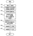
続いて、データ分析サーバ1で行う、低燃費走行(つまり、エコドライブ)の状態を可視化したレポート(以下、第2観点レポート)を出力するレポート出力関連処理について図5のフローチャートを用いて説明を行う。図5のフローチャートは、一例として、一週間ごとなどの定期的に実施される構成とすればよい。
<Report output related processing for eco-drive status>
Next, report output related processing for outputting a report (hereinafter referred to as second viewpoint report) visualizing the state of low fuel consumption driving (that is, eco-driving) performed by the
まず、ステップS21では、運行データ取得部11が、事業所別の複数の車両Vについての運行データを取得する。
First, in step S21, the operation
ステップS22では、S2と同様にして、S21で取得した運行データのうちの車両Vの運行開始時刻及び運行終了時刻から、運行状態特定部12が、時間帯ごとの各車両Vの稼働の有無を特定する。
In step S22, as in S2, the operation
ステップS23では、S21で取得した各車両Vの燃費の時系列データから、エコ関連情報特定部16が、各車両Vの平均燃費を特定する。
In step S23, the eco-related
ステップS24では、S21で取得した各車両Vの車速、エンジン回転数の時系列データ、及び高速道路/一般道路切換時刻から、エコ関連情報特定部16が、各車両Vの高速道路走行時と一般道路走行時とのそれぞれの車速、エンジン回転数の度数分布を特定する。また、S24では、S21で取得した各車両Vの前後Gから、エコ関連情報特定部16が、各車両Vの前後Gの度数分布を特定する。この車速、エンジン回転数、前後Gが請求項における走行中の運転操作によって変化する車両の状態値に相当する。
In step S24, the eco-related
高速道路と一般道路とのそれぞれの走行は、デフォルトの状態が一般道路の走行であるものとして、1回目の高速道路/一般道路切換時刻から2回目の高速道路/一般道路切換時刻までが一般道路の走行、2回目の高速道路/一般道路切換時刻から3回目の高速道路/一般道路切換時刻までが高速道路の走行といったように特定していくものとする。 As for the driving on the expressway and the general road, the default state is the driving on the general road, and the general road is from the first highway / general road switching time to the second highway / general road switching time. It is assumed that the driving from the second highway / general road switching time to the third highway / general road switching time is specified as driving on the highway.
ステップS25では、S21で取得した各車両Vの車速、エンジン回転数、走行距離の時系列データ、及び高速道路/一般道路切換時刻から、エコ関連情報特定部16が、各車両Vのアイドリング割合と高速道路走行割合といった、走行中の運転操作以外の要因によって変化する車両の状態値を特定する。
In step S25, the eco-related
アイドリング割合とは、運行データのうちの車速が実質的に0km/h(例えば車速5km/h未満)である場合における、エンジン回転数が例えば1000rpm等の所定回転数以上である場合の割合である。アイドリング割合は、運行データのうちの車速とエンジン回転数との時系列データから特定する。 The idling rate is a rate when the engine speed is equal to or higher than a predetermined speed such as 1000 rpm when the vehicle speed in the operation data is substantially 0 km / h (for example, less than 5 km / h). . The idling ratio is specified from time series data of the vehicle speed and the engine speed in the operation data.
高速道路走行割合とは、車両Vの走行距離のうちの高速道路の走行距離の割合である。高速道路走行割合は、運行データのうちの走行距離の時系列データと高速道路/一般道路切換時刻とから特定する。 The expressway travel ratio is the ratio of the travel distance of the expressway in the travel distance of the vehicle V. The highway travel ratio is specified from the time-series data of travel distance in the operation data and the highway / general road switching time.
ステップS26では、レポート作成部13が、S23で特定した各車両Vの平均燃費、S24で特定した各車両Vの高速道路走行時と一般道路走行時とのそれぞれの車速、エンジン回転数の度数分布、各車両Vの前後Gの度数分布、及びS25で特定した各車両Vのアイドリング割合と高速道路走行割合を示した表としての第2観点レポートを作成する。
In step S26, the
具体例としては、図6に示すように、平均燃費が高い車両Vほど上位になるように、車両Vごとに平均燃費、高速道路走行時と一般道路走行時とのそれぞれの車速、エンジン回転数の度数分布、アイドリング割合、高速道路走行割合、前後Gの度数分布を示す棒グラフを揃えて並べた表を作成する構成とすればよい。 As a specific example, as shown in FIG. 6, the average fuel consumption, the vehicle speed during highway traveling and the general road traveling, and the engine speed for each vehicle V so that the higher the average fuel consumption, the higher the vehicle V. A table in which bar graphs showing the frequency distribution, idling ratio, highway traveling ratio, and front and rear G frequency distributions are aligned and arranged may be created.
例えば、各車両Vの高速道路走行時と一般道路走行時とのそれぞれの車速、エンジン回転数の度数分布や各車両Vの前後Gは、縦軸を頻度、横軸を車速やエンジン回転数や前後Gといった状態値として表す構成とすればよい。前後Gについては横軸の中心を0とし、横軸の中心よりも左側を正の値、右側を負の値として表す構成とすればよい。なお、負の値の前後Gは減速度となる。 For example, the vehicle speed and the engine speed frequency distribution of each vehicle V when traveling on a highway and a general road, and the front and rear G of each vehicle V, the vertical axis represents frequency, the horizontal axis represents vehicle speed, engine speed, What is necessary is just to set it as the structure represented as state values, such as front and back G. The front and rear G may be configured such that the center of the horizontal axis is 0, the left side of the horizontal axis is a positive value, and the right side is a negative value. A negative value before and after G is a deceleration.
また、アイドリング割合や高速道路走行割合といった、走行中の運転操作以外の要因によって変化する車両の状態値が他の車両Vと比較して著しく異なる車両を抽出し、抽出した車両Vについては表から除外する構成としてもよい。アイドリング割合や高速道路走行割合が他の車両Vと比較して著しく異なることは、アイドリング割合や高速道路走行割合が各車両Vの標準偏差値から所定値以上乖離しているか否かによって判別する構成とすればよい。 In addition, a vehicle in which the state value of the vehicle that changes due to a factor other than the driving operation during traveling, such as an idling ratio and a highway driving ratio, is significantly different from that of the other vehicle V is extracted. It is good also as a structure to exclude. The configuration in which the idling ratio and the highway traveling ratio are significantly different from those of the other vehicles V is determined based on whether the idling ratio and the highway traveling ratio deviate from the standard deviation value of each vehicle V by a predetermined value or more. And it is sufficient.
これによれば、走行中の運転操作以外の要因によって変化する車両の状態値が他の車両Vと比較して著しく異なる車両のデータについては表から除外することで、走行中の運転操作によって変化する車両の状態値のみを対象として燃費が悪い場合の傾向をユーザが把握することが可能になる。その結果、燃費を向上させるための走行中の運転改善点をより容易に抽出することが可能になる。 According to this, the vehicle state value that changes due to factors other than the driving operation while traveling is significantly different from that of the other vehicle V, so that the data of the vehicle changes depending on the driving operation while traveling. It becomes possible for the user to grasp the tendency when the fuel efficiency is poor for only the state value of the vehicle to be operated. As a result, it is possible to more easily extract driving improvement points during traveling for improving fuel efficiency.
ステップS27では、S26で作成した第2観点レポートをレポート出力部14がネットワークを介してファイルサーバ5に送信する。
In step S27, the
ファイルサーバ5に送信された第2観点レポートは、PC4からファイルサーバ5にアクセスすることで、PC4のディスプレイに表示したりすることができる。ユーザは、PC4のディスプレイに表示される第2観点レポートを確認することで、燃費の悪い車速(図6のPo3)、燃費の悪いエンジン回転数(図6のPo4)、燃費の悪いアイドリング割合(図6のPo5)といった走行状態を容易に抽出することができ、エコドライブのための運転改善点を容易に抽出することが可能になる。従って、業務に用いられる複数の車両Vの運行に関して、より詳細な改善点が抽出しやすくなる。
The second viewpoint report transmitted to the
<ドライバの長時間運転の状態についてのレポート出力関連処理>
続いて、データ分析サーバ1で行う、車両Vの所定の条件を超える長時間運転の状態を可視化したレポート(以下、第3観点レポート)を出力するレポート出力関連処理について図7のフローチャートを用いて説明を行う。図7のフローチャートは、一例として、一週間ごとなどの定期的に実施される構成とすればよい。
<Report output related processing about the long-time driving status of the driver>
Subsequently, a report output related process for outputting a report (hereinafter referred to as a third viewpoint report) that visualizes a long-time driving state exceeding a predetermined condition of the vehicle V, which is performed by the
まず、ステップS41では、運行データ取得部11が、事業所別の複数の車両についての運行データを取得する。
First, in step S41, the operation
ステップS42では、S41で取得した運行データのうちの車両Vの車速の時系列データから、運行状態特定部12が、時間帯ごとの各車両Vの走行の有無を特定する。例えば、車速5km/h未満の期間が10分以上継続せずに車速5km/h以上で走行している時間帯を、車両Vが走行している時間と特定する。よって、車速が請求項における車両の走行を特定できる車両の状態値に相当する。なお、車両の走行を特定できる車両の状態値としてはエンジン回転数等を用いる構成としてもよい。
In step S42, from the time series data of the vehicle speed of the vehicle V in the operation data acquired in S41, the operation
ステップS43では、S41で取得した運行データのうちの車両Vの車速の時系列データから、長時間運転特定部15が、所定の条件を超える長時間運転を特定する。所定の条件を超える長時間運転としては、例えば車速が実質的に0km/h(例えば車速5km/h未満)となる停車が30分以上継続しない4時間以上にわたる走行(以下、連続運転)、2日間で18時間を超えた例えば車速5km/h以上の走行(以下、日またぎ超過運転)、2週間で88時間を超えた例えば車速5km/h以上の走行(以下、週またぎ超過運転)などがある。
In step S43, the long-time
ステップS44では、レポート作成部13が、S42で特定した時間帯ごとの各車両Vの走行の有無とS43で特定した各車両Vの長時間運転とから、時間帯ごとの各車両Vの走行の有無とその時間帯ごとの長時間運転の有無を示した表としての第3観点レポートを作成する。時間帯ごとの長時間運転の有無については、S42で特定した長時間運転が属する時間帯については、長時間運転有りとすればよい。
In step S44, the
具体例としては、図8に示すように、各車両Vについての1時間ごとの走行の有無と長時間運転の有無とを時間軸を揃えて並べたガントチャートを作成する構成とすればよい。また、図8に示すように、連続運転(図8のPo6参照)、日またぎ超過運転(図8のPo7参照)、週またぎ超過運転、連続運転と日またぎ超過運転とが重複した運転(図8のPo8)など、長時間運転の種類を区別できる態様で表すことが好ましい。 As a specific example, as shown in FIG. 8, a configuration may be used in which a Gantt chart is created in which the presence / absence of traveling for each hour for each vehicle V and the presence / absence of long-time driving are aligned on a time axis. Further, as shown in FIG. 8, continuous operation (see Po6 in FIG. 8), over-day operation (see Po7 in FIG. 8), over-week operation, continuous operation and over-day operation (see FIG. 8). It is preferable to express in a manner that can distinguish the type of long-time operation, such as 8 Po8).
ステップS45では、S44で作成した第3観点レポートをレポート出力部14がネットワークを介してファイルサーバ5に送信する。
In step S45, the
ファイルサーバ5に送信された第3観点レポートは、PC4からファイルサーバ5にアクセスすることで、PC4のディスプレイに表示したりすることができる。ユーザは、PC4のディスプレイに表示される第3観点レポートを確認することで、ドライバの疲労蓄積が大きいと推定される長時間運転(図8のF〜H参照)をどの車両がどの程度行っているのかを容易に抽出することができ、運行計画についての要改善点や長時間運転を改善する指導をすべきドライバを容易に抽出することが可能になる。従って、業務に用いられる複数の車両Vの運行に関して、より詳細な改善点が抽出しやすくなる。
The third viewpoint report transmitted to the
<消耗部品の使用頻度についてのレポート出力関連処理>
続いて、データ分析サーバ1で行う、車両Vの消耗部品の使用頻度を可視化したレポート(以下、第4観点レポート)を出力するレポート出力関連処理について図9のフローチャートを用いて説明を行う。図9のフローチャートは、一例として、一週間ごとなどの定期的に実施される構成とすればよい。
<Report output related processing of consumable parts usage frequency>
Next, a report output related process for outputting a report (hereinafter referred to as a fourth viewpoint report) visualizing the usage frequency of the consumable parts of the vehicle V, which is performed by the
まず、ステップS61では、運行データ取得部11が、事業所別の複数の車両についての運行データを取得する。
First, in step S61, the operation
ステップS62では、S61で取得した運行データのうちの車両Vの走行距離、エンジン回転数、IGオン信号、ACC信号、ブレーキスイッチ信号の時系列データから、使用頻度特定部17が、車両Vの累積走行距離、累積エンジン回転数、累積ACC/IGオン時間、累積ブレーキ回数を特定する。よって、車両Vの走行距離、エンジン回転数、IGオン信号、ACC信号、ブレーキスイッチ信号の時系列データが請求項の車両の消耗部品の使用頻度を示す情報に相当する。
In step S62, the use
例えば、累積走行距離、累積エンジン回転数については、図9のフローチャートが実施されるごとに、運行データ取得部11が取得した走行距離、エンジン回転数を積算していくことで特定する構成とすればよい。累積エンジン回転数はエンジンの使用頻度を示す情報とする。また、累積走行距離は車両Vの消耗部品全体の使用頻度を示す情報とする。
For example, the cumulative travel distance and the cumulative engine speed are identified by integrating the travel distance and engine speed acquired by the operation
累積ACC/IGオン時間は、ACCスイッチ及びIGスイッチのいずれかがオンになっている時間を積算したものである。ACCスイッチ及びIGスイッチのいずれかがオンになっている時間とは、IGオン信号及びACC信号のいずれかがハイレベルとなっている時間であって、運行データ取得部11が取得したIGオン信号、ACC信号の時系列データから算出できる。
The accumulated ACC / IG on time is obtained by integrating the time during which either the ACC switch or the IG switch is on. The time when either the ACC switch or the IG switch is on is the time when either the IG on signal or the ACC signal is at the high level, and the IG on signal acquired by the operation
累積ACC/IGオン時間については、図9のフローチャートが実施されるごとに、運行データ取得部11が取得したIGオン信号、ACC信号の時系列データから特定したACCスイッチ及びIGスイッチのいずれかがオンになっている時間を積算していくことで特定する構成とすればよい。累積ACC/IGオン時間は、バッテリの使用頻度を示す情報とする。
For the cumulative ACC / IG on time, every time the flowchart of FIG. 9 is executed, either the IG on signal acquired by the operation
累積ブレーキ回数は、ブレーキスイッチがオンになった回数、つまり、ブレーキペダルが踏まれた回数を積算したものである。ブレーキスイッチがオンになった回数は、ブレーキスイッチ信号がローレベルからハイレベルに切り換わった回数であって、運行データ取得部11が取得したブレーキスイッチ信号の時系列データから特定できる。
The cumulative number of brakes is the sum of the number of times the brake switch is turned on, that is, the number of times the brake pedal is depressed. The number of times the brake switch is turned on is the number of times the brake switch signal is switched from the low level to the high level, and can be specified from the time series data of the brake switch signal acquired by the operation
累積ブレーキ回数については、図9のフローチャートが実施されるごとに、運行データ取得部11が取得したブレーキスイッチ信号の時系列データから特定したブレーキスイッチがオンになった回数を積算していくことで特定する構成とすればよい。累積ブレーキ回数は、ブレーキの使用頻度を示す情報とする。
Regarding the cumulative number of brakes, every time the flowchart of FIG. 9 is executed, the number of times the brake switch specified by the time series data of the brake switch signal acquired by the operation
ステップS63では、レポート作成部13が、S62で特定した各車両Vの累積走行距離、累積エンジン回転数、累積ACC/IGオン時間、累積ブレーキ回数を示した表としての第4観点レポートを作成する。
In step S63, the
具体例としては、図10に示すように、車両Vごとの累積走行距離の棒グラフを並べた表(図10のA)、車両Vごとの累積エンジン回転数の棒グラフを並べた表(図10のB)、車両Vごとの累積ACC/IGオン時間の棒グラフを並べた表(図10のC)、車両Vごとの累積ブレーキ回数の棒グラフを並べた表(図10のD)をそれぞれ作成する構成とすればよい。 As a specific example, as shown in FIG. 10, a table (A in FIG. 10) in which the accumulated mileage bar graphs for each vehicle V are arranged, and a table (in FIG. 10) in which the accumulated engine revolutions for each vehicle V are arranged. B) A configuration in which a bar graph of accumulated ACC / IG on-time for each vehicle V is arranged (C in FIG. 10), and a table (D in FIG. 10) in which a bar graph of the cumulative number of brakes for each vehicle V is arranged. And it is sufficient.
ステップS64では、S63で作成した第4観点レポートをレポート出力部14がネットワークを介してファイルサーバ5に送信する。
In step S64, the
ファイルサーバ5に送信された第4観点レポートは、PC4からファイルサーバ5にアクセスすることで、PC4のディスプレイに表示したりすることができる。ユーザは、PC4のディスプレイに表示される第4観点レポートを確認することで、エンジンの使用頻度の高い車両V(図10のPo9参照)やバッテリの使用頻度の高い車両V(図10のPo10参照)やブレーキの使用頻度の高い車両V(図10のPo11参照)を容易に抽出することができ、どの車両Vのどの消耗部品を重点的に点検、整備する必要があるのかを容易に抽出することが可能になる。従って、業務に用いられる複数の車両Vの運行に関して、より詳細な改善点が抽出しやすくなる。
The fourth viewpoint report transmitted to the
(変形例1)
また、データ分析サーバ1は、改善点の目標(以下、改善目標)に対する実際の改善状況を示すデータを出力する構成(以下、変形例1)としてもよい。以下では、この変形例1について説明を行う。なお、説明の便宜上、この変形例1以降の説明において、それまでの実施形態の説明に用いた図に示した部材と同一の機能を有する部材については、同一の符号を付し、その説明を省略する。
(Modification 1)
In addition, the
変形例1のデータ分析サーバ1は、改善目標に対する実際の改善状況を示すデータを出力する処理に関連する機能を有する点を除けば、実施形態1のデータ分析サーバ1と同様である。
The
<変形例1のデータ分析サーバ1の詳細構成>
ここで、図11を用いて、変形例1のデータ分析サーバ1について説明を行う。図11では、便宜上、データ分析サーバ1に備えられる機能ブロックのうち、変形例1についての説明に必要な機能ブロックのみを記載している。
<Detailed Configuration of
Here, the
変形例1のデータ分析サーバ1は、運行データ取得部11、運行状態特定部12、レポート作成部13、レポート出力部14、長時間運転特定部15、エコ関連情報特定部16、使用頻度特定部17、稼働率目標設定部18、実稼働率特定部19、稼働率情報出力部20、空車率目標設定部21、実空車率特定部22、空車率情報出力部23、目標金額設定部24、実費特定部25、費用情報出力部26、発生回数目標設定部27、実発生回数特定部28、及び発生回数情報出力部29を備えている。
The
目標金額設定部24が請求項の効率関連値目標設定部に相当し、実費特定部25が請求項の実効率関連値特定部に相当し、費用情報出力部26が請求項の効率関連値情報出力部に相当する。
The target
<改善目標の設定>
続いて、改善目標の設定について説明を行う。改善目標の設定については、稼働率目標設定部18が車両Vの稼働率の改善目標を設定し、空車率目標設定部21が車両Vの空車率の改善目標を設定し、目標金額設定部24が車両Vの燃料費の改善目標を設定し、発生回数目標設定部27が前述の長時間運転の発生回数の改善目標を設定する。
<Setting improvement targets>
Next, the setting of improvement targets will be described. Regarding the setting of the improvement target, the operation rate
ここで言うところの稼働率とは、対象とする全時間帯に対しての、運行状態特定部12で車両Vの稼働有りと特定される時間帯の割合である。空車率とは、対象とする全時間帯のうちの車両Vの稼働有りと特定された全時間帯に対しての、運行状態特定部12で車両Vが空車状態と特定される時間帯の割合である。
The operating rate mentioned here is the ratio of the time zone in which the operation
改善目標の設定については、PC4を介してユーザが入力した値を稼働率目標設定部18や空車率目標設定部21や目標金額設定部24や発生回数目標設定部27が行う構成としてもよいし、データ分析サーバ1で自動的に行う構成としてもよい。
About the improvement target setting, it is good also as a structure which the operation rate
改善目標の設定をデータ分析サーバ1で自動的に行う場合には、後述する実稼働率特定部19、実空車率特定部22、実費特定部25、実発生回数特定部28で過去に特定した実績値に対して所定の割合を増減させた値を改善目標として稼働率目標設定部18や空車率目標設定部21や目標金額設定部24や発生回数目標設定部27が設定する構成とすればよい。
When the improvement target is automatically set by the
<改善目標に対する実際の改善状況を示すデータを出力する処理>
続いて、改善目標に対する実際の改善状況を示すデータを出力する処理についての説明を行う。まず、稼働率の改善目標に対する実際の稼働率の改善状況を示すデータを出力する処理(以下、第1改善状況出力処理)について説明を行う。
<Process to output data indicating actual improvement status against improvement target>
Subsequently, a process for outputting data indicating an actual improvement status with respect to the improvement target will be described. First, a process of outputting data indicating the actual operating rate improvement status with respect to the operating rate improvement target (hereinafter referred to as a first improving status output process) will be described.
第1改善状況出力処理では、稼働率目標設定部18が車両Vの稼働率の改善目標を設定する。また、実稼働率特定部19が、運行データ取得部11で取得した事業所別の複数の車両についての運行データから、所定の期間(例えば1か月とする)ごとに、車両Vの稼働率の実績値を特定する。具体例としては、1か月の全時間帯に対する、前述のS2の処理と同様にして特定した各車両Vの稼働有りの時間帯の割合を、車両Vの稼働率の実績値として特定する。
In the first improvement status output process, the operation rate
そして、稼働率情報出力部20が、実稼働率特定部19で特定した1か月ごとの稼働率の実績値と稼働率目標設定部18で設定した稼働率の目標値とを比較可能な態様で示した表を、ネットワークを介してファイルサーバ5に送信する。
Then, the operation rate
稼働率の実績値と目標値とを比較可能な態様で示した表の一例としては、図12のEに示すように、1か月ごとの稼働率の実績値を結んだ折れ線グラフ(図12のI参照)と、稼働率の目標値を表す破線(図12のJ参照)とを示した表を用いる構成とすればよい。 As an example of the table in which the actual value of the operation rate can be compared with the target value, as shown in E of FIG. 12, a line graph (FIG. 12) connecting the actual values of the operation rate every month. And a table showing a broken line (see J in FIG. 12) indicating the target value of the operation rate.
稼働率の実績値と目標値とを比較可能な態様で示した表は、PC4からファイルサーバ5にアクセスすることで、PC4のディスプレイに表示したりすることができる。ユーザは、PC4のディスプレイに表示されるその表を確認することで、稼働率の改善状況を把握することが可能になるので、稼働率の改善状況のフィードバックを受けながら、稼働率の改善を図ることが可能になる。
The table shown in an aspect in which the actual value of the operation rate and the target value can be compared can be displayed on the display of the
続いて、空車率の改善目標に対する実際の空車率の改善状況を示すデータを出力する処理(以下、第2改善状況出力処理)について説明を行う。 Subsequently, a process of outputting data indicating the actual improvement rate of the empty vehicle rate with respect to the improvement target of the empty vehicle rate (hereinafter referred to as a second improvement status output process) will be described.
第2改善状況出力処理では、空車率目標設定部21が車両Vの空車率の改善目標を設定する。また、実空車率特定部22が、運行データ取得部11で取得した事業所別の複数の車両についての運行データから、所定の期間(例えば1か月とする)ごとに、車両Vの空車率の実績値を特定する。具体例としては、1か月の全時間帯のうちの各車両Vの稼働有りの時間帯に対する、前述のS3の処理と同様にして特定した各車両Vの空車状態の時間帯の割合を、車両Vの空車率の実績値として特定する。
In the second improvement status output process, the empty vehicle rate
そして、空車率情報出力部23が、実空車率特定部22で特定した1か月ごとの空車率の実績値と空車率目標設定部21で設定した空車率の目標値とを比較可能な態様で示した表を、ネットワークを介してファイルサーバ5に送信する。
Then, the empty vehicle rate
空車率の実績値と目標値とを比較可能な態様で示した表の一例としては、図12のFに示すように、1か月ごとの空車率の実績値を結んだ折れ線グラフ(図12のK参照)と、空車率の目標値を表す破線(図12のL参照)とを示した表を用いる構成とすればよい。 As an example of the table in which the actual value of the empty vehicle rate and the target value can be compared with each other, as shown in F of FIG. 12, a line graph connecting the actual values of the empty vehicle rate for each month (FIG. 12). And a table showing a broken line (see L in FIG. 12) indicating the target value of the empty vehicle rate.
空車率の実績値と目標値とを比較可能な態様で示した表は、PC4からファイルサーバ5にアクセスすることで、PC4のディスプレイに表示したりすることができる。ユーザは、PC4のディスプレイに表示されるその表を確認することで、空車率の改善状況を把握することが可能になるので、空車率の改善状況のフィードバックを受けながら、空車率の改善を図ることが可能になる。
The table showing the comparison of the actual value and the target value of the vacancy rate can be displayed on the display of the
なお、ここでは空車率を用いる構成を示したが、必ずしもこれに限らず、空車率の代わりに実車率を用いる構成としてもよい。 In addition, although the structure using an empty vehicle rate was shown here, it is not necessarily restricted to this, It is good also as a structure which uses an actual vehicle rate instead of an empty vehicle rate.
続いて、燃料費の改善目標に対する実際の燃料費の改善状況を示すデータを出力する処理(以下、第3改善状況出力処理)について説明を行う。燃料費が請求項の消費効率関連値に相当する。 Subsequently, a process of outputting data indicating the actual fuel cost improvement status with respect to the fuel cost improvement target (hereinafter, third improvement status output process) will be described. The fuel cost corresponds to the consumption efficiency related value in the claims.
第3改善状況出力処理では、目標金額設定部24が車両Vの燃料費の改善目標を設定する。また、実費特定部25が、運行データ取得部11で取得した事業所別の複数の車両についての運行データと燃料の単価とから、所定の期間(例えば1か月とする)ごとに、車両Vの燃料費の実績値を特定する。具体例としては、1か月の各車両Vの走行距離と、S23と同様にして特定した各車両Vの平均燃費と、燃料の単価とから算出した1か月の各車両Vの全体での燃料費を、各車両Vの燃料費の実績値として特定する。燃料の単価については、固定値であってもよいし、PC4を介してユーザが逐次入力する構成としてもよい。
In the third improvement status output process, the target
そして、費用情報出力部26が、実費特定部25で特定した1か月ごとの燃料費の実績値と目標金額設定部24で設定した燃料費の目標値とを比較可能な態様で示した表を、ネットワークを介してファイルサーバ5に送信する。
The cost
燃料費の実績値と目標値とを比較可能な態様で示した表の一例としては、図12のGに示すように、1か月ごとの燃料費の実績値を結んだ折れ線グラフ(図12のM参照)と、燃料費の目標値を表す破線(図12のN参照)とを示した表を用いる構成とすればよい。 As an example of a table in which the actual value of fuel cost and the target value can be compared with each other, as shown in G of FIG. 12, a line graph connecting actual values of fuel cost for each month (FIG. 12). And a table showing a broken line (see N in FIG. 12) indicating the target value of the fuel cost.
燃料費の実績値と目標値とを比較可能な態様で示した表は、PC4からファイルサーバ5にアクセスすることで、PC4のディスプレイに表示したりすることができる。ユーザは、PC4のディスプレイに表示されるその表を確認することで、燃料費の改善状況を把握することが可能になるので、燃料費の改善状況のフィードバックを受けながら、燃料費の改善を図ることが可能になる。
The table showing the comparison of the actual value and the target value of the fuel cost can be displayed on the display of the
なお、燃料費でなく、所定の期間ごとの燃費の実績値と目標値とを比較可能な態様で示した表を出力する構成としてもよい。 In addition, it is good also as a structure which outputs the table | surface shown in the aspect which can compare the actual value and target value of a fuel consumption for every predetermined period instead of fuel cost.
続いて、長時間運転の発生回数の改善目標に対する実際の長時間運転の発生回数の改善状況を示すデータを出力する処理(以下、第4改善状況出力処理)について説明を行う。 Subsequently, a process of outputting data indicating the improvement status of the actual number of occurrences of long-time driving with respect to the improvement target of the number of occurrences of long-time driving (hereinafter referred to as a fourth improvement status output process) will be described.
第4改善状況出力処理では、発生回数目標設定部27が車両Vの長時間運転の発生回数の改善目標を設定する。また、実発生回数特定部28が、運行データ取得部11で取得した事業所別の複数の車両についての運行データから、所定の期間(例えば1か月とする)ごとに、車両Vの長時間運転の発生回数の実績値を特定する。具体例としては、1か月のうちでの、前述のS43の処理と同様にして特定した各車両Vの長時間運転の発生回数を、車両Vの長時間運転の発生回数の実績値として特定する。
In the fourth improvement status output process, the occurrence frequency
そして、発生回数情報出力部29が、実発生回数特定部28で特定した1か月ごとの長時間運転の発生回数の実績値と発生回数目標設定部27で設定した長時間運転の発生回数の目標値とを比較可能な態様で示した表を、ネットワークを介してファイルサーバ5に送信する。
Then, the number-of-occurrence-number
長時間運転の発生回数の実績値と目標値とを比較可能な態様で示した表の一例としては、図12のHに示すように、1か月ごとの長時間運転の発生回数の実績値を結んだ折れ線グラフ(図12のO参照)と、長時間運転の発生回数の目標値を表す破線(図12のP参照)とを示した表を用いる構成とすればよい。 As an example of the table shown in a manner in which the actual value of the number of occurrences of long-time operation and the target value can be compared, as shown in H of FIG. 12, the actual value of the number of occurrences of long-time operation per month And a table showing a line graph (see O in FIG. 12) and a broken line (see P in FIG. 12) indicating the target value of the number of occurrences of long-time operation.
長時間運転の発生回数の実績値と目標値とを比較可能な態様で示した表は、PC4からファイルサーバ5にアクセスすることで、PC4のディスプレイに表示したりすることができる。ユーザは、PC4のディスプレイに表示されるその表を確認することで、長時間運転の発生回数の改善状況を把握することが可能になるので、長時間運転の発生回数の改善状況のフィードバックを受けながら、長時間運転の発生回数の改善を図ることが可能になる。
The table shown in an aspect in which the actual value of the number of occurrences of long-time driving and the target value can be compared can be displayed on the display of the
(変形例2)
前述の実施形態では、一例としてSDカード3を用いる構成を示したが、必ずしもこれに限らない。例えば、電気的に書き換え可能な不揮発性の記憶媒体であって、且つ、リムーバブルな記憶媒体であれば、SDカード以外の記憶媒体を用いる構成としてもよい。
(Modification 2)
In the above-described embodiment, the configuration using the
(変形例3)
また、車両Vの運行データを、リムーバブルな記憶媒体を用いて運行記録装置2から車両Vの外部に持ち出す構成を示したが、必ずしもこれに限らない。例えば、運行記録装置2が記録した運行データを、DCM(Data Communication Module)等の車載通信モジュールを用いた通信によってファイルサーバ5に送信する構成としてもよい。
(Modification 3)
Moreover, although the structure which takes out the operation data of the vehicle V from the
(変形例4、5)
前述の実施形態では、事業所別にレポートを作成して出力する構成を示したが、必ずしもこれに限らない。例えば、事業所内のグループ別など、まとまりを特定できる識別子を運行データに付与することで、様々なまとまり単位でレポートを作成、出力する構成(以下、変形例4)としてもよい。また、全事業所単位のレポートを作成して出力する構成(以下、変形例5)としてもよい。
(
In the above-described embodiment, a configuration has been described in which a report is generated and output for each business location, but is not necessarily limited thereto. For example, it is good also as a structure (henceforth the modification 4) which produces and outputs a report by various unit by giving the identifier which can specify a group, such as according to the group in an office, to operation data. Moreover, it is good also as a structure (henceforth the modification 5) which produces and outputs the report of all the establishments.
(変形例6)
また、運行管理システム100は、輸送業務以外にも営業に用いる車両の運行管理業務に用いる構成としてもよい。この場合には、前述の第2観点レポートや第4観点レポートを出力するレポート出力関連処理に限定して実施する構成などとすればよい。
(Modification 6)
Further, the
(変形例7)
前述の実施形態では、車両Vがエンジン車やエンジンと電気モータとを併用するハイブリッド車である場合の例を示したが、車両Vは電気自動車であってもよい。車両Vが電気自動車の場合には、燃費の代わりの走行用エネルギーの消費効率として電費を用いたり、エンジン回転数の代わりに電気モータの回転数を用いたりする構成とすればよい。
(Modification 7)
In the above-described embodiment, an example in which the vehicle V is an engine vehicle or a hybrid vehicle using an engine and an electric motor together has been described. However, the vehicle V may be an electric vehicle. In the case where the vehicle V is an electric vehicle, the power consumption may be used as the energy consumption efficiency instead of the fuel consumption, or the electric motor speed may be used instead of the engine speed.
なお、本発明は、上述した各実施形態に限定されるものではなく、請求項に示した範囲で種々の変更が可能であり、異なる実施形態にそれぞれ開示された技術的手段を適宜組み合わせて得られる実施形態についても本発明の技術的範囲に含まれる。 The present invention is not limited to the above-described embodiments, and various modifications can be made within the scope of the claims, and the technical means disclosed in different embodiments can be appropriately combined. Such embodiments are also included in the technical scope of the present invention.
1 データ分析サーバ(運行管理装置)、11 運行データ取得部、12 運行状態特定部、13 レポート作成部、14 レポート出力部、15 長時間運転特定部、100 運行管理システム
DESCRIPTION OF
Claims (9)
前記運行データには、前記車両の運行開始及び運行終了の時刻、並びに前記車両の実車走行の開始及び終了時刻と空車走行の開始及び終了時刻とを含み、
前記運行データ取得部で取得した前記車両の運行開始及び運行終了の時刻から、時間帯ごとの前記車両の稼働の有無を特定するとともに、前記運行データ取得部で取得した前記車両の実車走行の開始及び終了時刻と空車走行の開始及び終了時刻とから、時間帯ごとの前記車両が実車走行か空車走行かの実車/空車状態も特定する運行状態特定部(12)と、
前記運行状態特定部で特定した時間帯ごとの複数の前記車両の稼働の有無及び前記実車/空車状態から、時間帯ごとの各車両の稼働の有無と各車両の実車/空車状態とを示した表を作成するレポート作成部(13)と、
前記レポート作成部で作成した、時間帯ごとの各車両の稼働の有無と各車両の実車/空車状態とを示した表を出力するレポート出力部(14)とを備えることを特徴とする運行管理装置。 An operation management device that is used in an operation management system (100) that manages the operation of a plurality of vehicles used for transportation work, and that includes an operation data acquisition unit (11) that acquires operation data of the plurality of vehicles,
The operation data includes the operation start and operation end times of the vehicle, the actual vehicle start and end times of the vehicle, and the start and end times of empty vehicle operation,
From the operation start and operation end time of the vehicle acquired by the operation data acquisition unit, the presence or absence of operation of the vehicle for each time zone is specified, and the start of actual vehicle travel of the vehicle acquired by the operation data acquisition unit And an operation state specifying unit (12) for specifying an actual vehicle / empty state whether the vehicle for each time zone is an actual vehicle run or an empty vehicle run from an end time and an empty vehicle start and end time;
From the presence / absence of operation of the plurality of vehicles and the actual vehicle / empty state for each time zone specified by the operation state specifying unit, the presence / absence of operation of each vehicle for each time zone and the actual vehicle / empty state of each vehicle are shown. A report creation unit (13) for creating a table;
An operation management comprising: a report output unit (14) that outputs a table created by the report creation unit and indicating whether or not each vehicle is operating for each time period and an actual vehicle / empty state of each vehicle. apparatus.
前記車両の業務時間帯における稼働の割合である稼働率の目標値を設定する稼働率目標設定部(18)と、
前記運行データ取得部で取得した前記車両の運行データから、所定の期間ごとに前記車両の稼働率の実績値を特定する実稼働率特定部(19)と、
前記実稼働率特定部で所定の期間ごとに特定した稼働率の実績値と、前記稼働率目標設定部で設定した稼働率の目標値とを比較可能な態様で示した情報を出力する稼働率情報出力部(20)とを備えることを特徴とする運行管理装置。 In claim 1,
An operation rate target setting unit (18) for setting a target value of the operation rate, which is the rate of operation of the vehicle during business hours;
From the operation data of the vehicle acquired by the operation data acquisition unit, an actual operation rate specifying unit (19) for specifying the actual value of the operation rate of the vehicle for each predetermined period;
An operating rate that outputs information indicating an aspect in which the actual value of the operating rate specified by the actual operating rate specifying unit for each predetermined period and the target value of the operating rate set by the operating rate target setting unit can be compared. An operation management device comprising an information output unit (20).
前記車両が稼働中の時間帯における空車走行の割合である空車率の目標値を設定する空車率目標設定部(21)と、
前記運行データ取得部で取得した前記車両の運行データから、所定の期間ごとに前記車両の空車率の実績値を特定する実空車率特定部(22)と、
前記実空車率特定部で所定の期間ごとに特定した空車率の実績値と、前記空車率目標設定部で設定した空車率の目標値とを比較可能な態様で示した情報を出力する空車率情報出力部(23)とを備えることを特徴とする運行管理装置。 In claim 1 or 2,
An empty rate target setting unit (21) for setting a target value of an empty rate that is a rate of empty running in a time zone during which the vehicle is operating;
An actual empty vehicle rate specifying unit (22) for specifying an actual value of the empty rate of the vehicle for each predetermined period from the operation data of the vehicle acquired by the operation data acquiring unit;
An empty vehicle rate that outputs information indicating a mode in which the actual value of the empty vehicle rate specified by the actual empty vehicle rate specifying unit for each predetermined period and the target value of the empty vehicle rate set by the empty vehicle rate target setting unit can be compared. An operation management device comprising an information output unit (23).
前記運行データには、前記車両の走行用エネルギーの消費効率と、その消費効率に影響を与える、走行中の運転操作によって変化する前記車両の状態値とを含み、
前記運行データ取得部で取得した複数の前記車両の走行用エネルギーの消費効率と、前記状態値とから、複数の前記車両別に、走行用エネルギーの消費効率と、その消費効率に影響を与える前記状態値の度数分布とを関連付けて示した表を作成するレポート作成部(13)と、
前記レポート作成部で作成した、複数の前記車両別に走行用エネルギーの消費効率とその消費効率に影響を与える前記状態値の度数分布とを関連付けて示した表を出力するレポート出力部(14)とを備えることを特徴とする運行管理装置。 An operation management device including an operation data acquisition unit (11) for acquiring operation data of a plurality of vehicles, which is used in an operation management system that manages the operation of a plurality of vehicles used for business.
The operation data includes the consumption efficiency of driving energy of the vehicle, and the state value of the vehicle, which affects the consumption efficiency and changes according to the driving operation during driving,
The consumption energy consumption efficiency of the plurality of vehicles acquired by the operation data acquisition unit and the state value, the consumption energy consumption efficiency for the plurality of vehicles, and the state that affects the consumption efficiency A report creation unit (13) for creating a table showing the frequency distribution of values in association with each other;
A report output unit (14) that outputs a table created by the report creation unit in association with consumption efficiency of travel energy for each of the plurality of vehicles and the frequency distribution of the state values that affect the consumption efficiency; An operation management device comprising:
前記レポート作成部は、前記運行データ取得部で取得した複数の前記車両の走行用エネルギーの消費効率から、複数の前記車両別に、走行用エネルギーの消費効率と、その消費効率に影響を与える前記状態値の度数分布とを関連付けて示した前記表を作成する場合に、前記走行用エネルギーの消費効率が良い車両順に並べた前記表を作成し、
前記レポート出力部は、前記走行用エネルギーの消費効率が良い車両順に並べた前記表を出力することを特徴とする運行管理装置。 In claim 4,
The report creating unit, from the consumption efficiency of the driving energy of the plurality of vehicles acquired by the operation data acquisition unit, for each of the plurality of vehicles, the consumption energy of the driving energy, and the state that affects the consumption efficiency When creating the table shown in association with the frequency distribution of values, create the table arranged in order of vehicles with good consumption efficiency of the travel energy,
The operation management apparatus characterized in that the report output unit outputs the table arranged in the order of vehicles in which the travel energy consumption efficiency is good.
前記車両の走行用エネルギーの消費効率に関連する消費効率関連値の目標値を設定する効率関連値目標設定部(24)と、
前記運行データ取得部で取得した前記車両の運行データから、所定の期間ごとに前記車両の走行用エネルギーの消費効率に関連する前記消費効率関連値の実績値を特定する実効率関連値特定部(25)と、
前記実効率関連値特定部で所定の期間ごとに特定した前記消費効率関連値の実績値と、前記効率関連値目標設定部で設定した前記消費効率関連値の目標値とを比較可能な態様で示した情報を出力する効率関連値情報出力部(26)とを備えることを特徴とする運行管理装置。 In claim 4 or 5,
An efficiency-related value target setting unit (24) for setting a target value of a consumption efficiency-related value related to the consumption efficiency of the vehicle travel energy;
An actual efficiency related value specifying unit that specifies the actual value of the consumption efficiency related value related to the consumption efficiency of the driving energy of the vehicle for each predetermined period from the operation data of the vehicle acquired by the operation data acquisition unit ( 25)
In an aspect in which the actual value of the consumption efficiency related value specified for each predetermined period by the actual efficiency related value specifying unit and the target value of the consumption efficiency related value set by the efficiency related value target setting unit can be compared. An operation management device comprising an efficiency-related value information output unit (26) for outputting the indicated information.
前記運行データには、前記車両の走行を特定できる前記車両の状態値の時系列データを含み、
前記運行データ取得部で取得した前記車両の走行を特定できる前記車両の状態値の時系列データから、時間帯ごとの前記車両の走行の有無を特定する運行状態特定部(12)と、
前記運行データ取得部で取得した前記車両の走行を特定できる前記車両の状態値の時系列データから、所定の条件を超える前記車両の長時間運転を特定する長時間運転特定部(15)と、
前記運行状態特定部で特定した時間帯ごとの前記車両の走行の有無と、前記長時間運転特定部で特定した長時間運転とから、時間帯ごとの各車両の走行の有無と前記長時間運転の有無とを示した表を作成するレポート作成部(13)と、
前記レポート作成部で作成した、時間帯ごとの各車両の所定時間以上の運転の有無と前記長時間運転の有無とを示した表を出力するレポート出力部(14)とを備えることを特徴とする運行管理装置。 An operation management device including an operation data acquisition unit (11) for acquiring operation data of a plurality of vehicles, which is used in an operation management system that manages the operation of a plurality of vehicles used for business.
The operation data includes time-series data of state values of the vehicle that can specify the traveling of the vehicle,
From the time series data of the state value of the vehicle that can specify the travel of the vehicle acquired by the operation data acquisition unit, an operation state specifying unit (12) that specifies whether or not the vehicle is traveling for each time zone;
A long-time operation specifying unit (15) for specifying long-time driving of the vehicle exceeding a predetermined condition from time-series data of the state values of the vehicle that can specify the traveling of the vehicle acquired by the operation data acquiring unit;
From the presence / absence of traveling of the vehicle for each time period specified by the operation state specifying unit and the long-time driving specified by the long-time driving specifying unit, the presence / absence of driving of each vehicle for each time period and the long-time driving A report creation unit (13) that creates a table indicating the presence or absence of
A report output unit (14) that outputs a table created by the report creation unit and indicating whether or not each vehicle has been operated for a predetermined time or more for each time period and whether or not the vehicle has been operated for a long time. Operation management device to do.
前記長時間運転の発生回数の目標値を設定する発生回数目標設定部(27)と、
前記運行データ取得部で取得した前記車両の走行を特定できる前記車両の状態値の時系列データから、所定の期間ごとに前記車両の前記長時間運転の発生回数を特定する実発生回数特定部(28)と、
前記実発生回数特定部で所定の期間ごとに特定した長時間運転の発生回数と、前記発生回数目標設定部で設定した長時間運転の発生回数の目標値とを比較可能な態様で示した情報を出力する発生回数情報出力部(29)とを備えることを特徴とする運行管理装置。 In claim 7,
An occurrence frequency target setting unit (27) for setting a target value of the occurrence frequency of the long-time operation;
From the time series data of the state values of the vehicle that can specify the travel of the vehicle acquired by the operation data acquisition unit, an actual occurrence number specifying unit that specifies the number of occurrences of the long-time driving of the vehicle every predetermined period ( 28)
Information indicating in a manner in which the number of occurrences of long-time operation specified for each predetermined period by the actual occurrence number specifying unit and the target value of the number of occurrences of long-time operation set by the generation number target setting unit can be compared And an occurrence number information output unit (29).
前記運行データには、前記車両の消耗部品の使用頻度を示す情報を含み、
前記運行データ取得部で取得した前記車両の消耗部品の使用頻度を示す情報から、複数の前記車両別にその車両の消耗部品の使用頻度を示した表を作成するレポート作成部(13)と、
前記レポート作成部で作成した、複数の前記車両別にその車両の消耗部品の使用頻度を示した表を出力するレポート出力部(14)とを備えることを特徴とする運行管理装置。 An operation management device including an operation data acquisition unit (11) for acquiring operation data of a plurality of vehicles, which is used in an operation management system that manages the operation of a plurality of vehicles used for business.
The operation data includes information indicating the use frequency of the consumable parts of the vehicle,
A report creation unit (13) that creates a table showing the frequency of use of consumable parts of the vehicle for each of the plurality of vehicles from information indicating the use frequency of the consumable parts of the vehicle acquired by the operation data acquisition unit;
An operation management apparatus comprising: a report output unit (14) that outputs a table created by the report creation unit and indicating a use frequency of consumable parts of the vehicle for each of the plurality of vehicles.
Priority Applications (1)
| Application Number | Priority Date | Filing Date | Title |
|---|---|---|---|
| JP2014139695A JP2016018317A (en) | 2014-07-07 | 2014-07-07 | Operation management device |
Applications Claiming Priority (1)
| Application Number | Priority Date | Filing Date | Title |
|---|---|---|---|
| JP2014139695A JP2016018317A (en) | 2014-07-07 | 2014-07-07 | Operation management device |
Publications (1)
| Publication Number | Publication Date |
|---|---|
| JP2016018317A true JP2016018317A (en) | 2016-02-01 |
Family
ID=55233516
Family Applications (1)
| Application Number | Title | Priority Date | Filing Date |
|---|---|---|---|
| JP2014139695A Pending JP2016018317A (en) | 2014-07-07 | 2014-07-07 | Operation management device |
Country Status (1)
| Country | Link |
|---|---|
| JP (1) | JP2016018317A (en) |
Cited By (7)
| Publication number | Priority date | Publication date | Assignee | Title |
|---|---|---|---|---|
| JP2018104930A (en) * | 2016-12-22 | 2018-07-05 | コベルコ建機株式会社 | Construction machinery |
| JP2019519713A (en) * | 2016-05-27 | 2019-07-11 | パーキンズ エンジンズ カンパニー リミテッドPerkins Engines Company Limited | Engine data logger |
| CN110920689A (en) * | 2019-10-16 | 2020-03-27 | 北京万相融通科技股份有限公司 | Operation progress monitoring method and system |
| CN110920688A (en) * | 2019-10-16 | 2020-03-27 | 北京万相融通科技股份有限公司 | Operation progress monitoring method and system |
| JP2022128223A (en) * | 2021-02-22 | 2022-09-01 | トヨタ自動車株式会社 | Information processor, program, and method for processing information |
| CN115511300A (en) * | 2022-09-27 | 2022-12-23 | 北京悟空出行科技有限公司 | Vehicle platoon car map generation method and device, electronic equipment and storage medium |
| JP2023017244A (en) * | 2021-07-26 | 2023-02-07 | 株式会社Nttドコモ | Information processing equipment |
Citations (5)
| Publication number | Priority date | Publication date | Assignee | Title |
|---|---|---|---|---|
| JP2001266200A (en) * | 2000-03-17 | 2001-09-28 | Komatsu Ltd | Mobile work report creation device and billing device |
| JP2003030289A (en) * | 2001-07-11 | 2003-01-31 | Tokyo Kaijo Risk Consulting Kk | Driving control system for vehicle, constituent article thereof, computer program and recording medium |
| JP2006057484A (en) * | 2004-08-18 | 2006-03-02 | Nissan Diesel Motor Co Ltd | Fuel consumption evaluation system |
| JP2010182108A (en) * | 2009-02-05 | 2010-08-19 | Denso Corp | Mobile device and vehicle system |
| JP2010231776A (en) * | 2009-03-04 | 2010-10-14 | Denso Corp | Driving assistance device |
-
2014
- 2014-07-07 JP JP2014139695A patent/JP2016018317A/en active Pending
Patent Citations (5)
| Publication number | Priority date | Publication date | Assignee | Title |
|---|---|---|---|---|
| JP2001266200A (en) * | 2000-03-17 | 2001-09-28 | Komatsu Ltd | Mobile work report creation device and billing device |
| JP2003030289A (en) * | 2001-07-11 | 2003-01-31 | Tokyo Kaijo Risk Consulting Kk | Driving control system for vehicle, constituent article thereof, computer program and recording medium |
| JP2006057484A (en) * | 2004-08-18 | 2006-03-02 | Nissan Diesel Motor Co Ltd | Fuel consumption evaluation system |
| JP2010182108A (en) * | 2009-02-05 | 2010-08-19 | Denso Corp | Mobile device and vehicle system |
| JP2010231776A (en) * | 2009-03-04 | 2010-10-14 | Denso Corp | Driving assistance device |
Cited By (12)
| Publication number | Priority date | Publication date | Assignee | Title |
|---|---|---|---|---|
| JP2019519713A (en) * | 2016-05-27 | 2019-07-11 | パーキンズ エンジンズ カンパニー リミテッドPerkins Engines Company Limited | Engine data logger |
| JP2018104930A (en) * | 2016-12-22 | 2018-07-05 | コベルコ建機株式会社 | Construction machinery |
| CN110920689A (en) * | 2019-10-16 | 2020-03-27 | 北京万相融通科技股份有限公司 | Operation progress monitoring method and system |
| CN110920688A (en) * | 2019-10-16 | 2020-03-27 | 北京万相融通科技股份有限公司 | Operation progress monitoring method and system |
| CN110920689B (en) * | 2019-10-16 | 2022-03-11 | 北京万相融通科技股份有限公司 | Operation progress monitoring method and system |
| CN110920688B (en) * | 2019-10-16 | 2022-05-06 | 北京万相融通科技股份有限公司 | Operation progress monitoring method and system |
| JP2022128223A (en) * | 2021-02-22 | 2022-09-01 | トヨタ自動車株式会社 | Information processor, program, and method for processing information |
| JP7415978B2 (en) | 2021-02-22 | 2024-01-17 | トヨタ自動車株式会社 | Information processing device, program and information processing method |
| US11987121B2 (en) | 2021-02-22 | 2024-05-21 | Toyota Jidosha Kabushiki Kaisha | Information processing device, program, and information processing method |
| JP2023017244A (en) * | 2021-07-26 | 2023-02-07 | 株式会社Nttドコモ | Information processing equipment |
| JP7553409B2 (en) | 2021-07-26 | 2024-09-18 | 株式会社Nttドコモ | Information processing device |
| CN115511300A (en) * | 2022-09-27 | 2022-12-23 | 北京悟空出行科技有限公司 | Vehicle platoon car map generation method and device, electronic equipment and storage medium |
Similar Documents
| Publication | Publication Date | Title |
|---|---|---|
| JP2016018317A (en) | Operation management device | |
| US8346420B2 (en) | System and method for predicting vehicle energy consumption | |
| Amarasinghe et al. | Cloud-based driver monitoring and vehicle diagnostic with OBD2 telematics | |
| CN102881057B (en) | Based on vehicle management system and the vehicles management method thereof of iOBD | |
| US11657074B2 (en) | Systems and methods for database geocoding | |
| CN103890816B (en) | System and method for evaluating vehicle accidents | |
| JP6635087B2 (en) | Operation support device and operation support method | |
| JP3044025B1 (en) | Operation management system capable of analyzing driving tendency and its constituent devices | |
| US20170103101A1 (en) | System for database data quality processing | |
| US20070239322A1 (en) | Generating a numerical ranking of driver performance based on a plurality of metrics | |
| EP3776493B1 (en) | Method and system to improve driver information and vehicle maintenance | |
| CN108717784B (en) | Network appointment vehicle supervision method and device and computer readable storage medium | |
| CN115027485B (en) | Driving behavior analysis method and system | |
| CN103295066A (en) | Systems and methods for advising customers regarding vehicle operation and maintenance | |
| DE102024102314A1 (en) | PREDICTING MAINTENANCE WORK FOR A VEHICLE FLEET | |
| CN113263993B (en) | Fault early warning method, device, communication equipment and storage medium | |
| US11577623B2 (en) | System for predicting battery usage habits and battery discharge tendencies | |
| KR101807210B1 (en) | Apparatus and method for managing vehicle expendable | |
| CN103010120A (en) | Vehicle display system and method | |
| US20200160412A1 (en) | Server device and information providing method | |
| CN105761002A (en) | Driving behavior evaluation method and driving behavior evaluation system | |
| JP2007312581A (en) | Electric vehicle energy management system | |
| JP6032145B2 (en) | Vehicle operation data analysis system | |
| CN111845358B (en) | Method and system for calculating the drivable distance for each vehicle driving mode | |
| JP7633029B2 (en) | Information processing device, information processing method, and information processing system |
Legal Events
| Date | Code | Title | Description |
|---|---|---|---|
| A621 | Written request for application examination |
Free format text: JAPANESE INTERMEDIATE CODE: A621 Effective date: 20160909 |
|
| A977 | Report on retrieval |
Free format text: JAPANESE INTERMEDIATE CODE: A971007 Effective date: 20170914 |
|
| A131 | Notification of reasons for refusal |
Free format text: JAPANESE INTERMEDIATE CODE: A131 Effective date: 20170919 |
|
| A02 | Decision of refusal |
Free format text: JAPANESE INTERMEDIATE CODE: A02 Effective date: 20180327 |