JP2016017444A - Compressor - Google Patents
Compressor Download PDFInfo
- Publication number
- JP2016017444A JP2016017444A JP2014139921A JP2014139921A JP2016017444A JP 2016017444 A JP2016017444 A JP 2016017444A JP 2014139921 A JP2014139921 A JP 2014139921A JP 2014139921 A JP2014139921 A JP 2014139921A JP 2016017444 A JP2016017444 A JP 2016017444A
- Authority
- JP
- Japan
- Prior art keywords
- accumulator
- outlet pipe
- compressor
- suction port
- outlet
- Prior art date
- Legal status (The legal status is an assumption and is not a legal conclusion. Google has not performed a legal analysis and makes no representation as to the accuracy of the status listed.)
- Pending
Links
Images
Landscapes
- Compressor (AREA)
- Applications Or Details Of Rotary Compressors (AREA)
Abstract
【課題】運転音のばらつきを容易に防ぐことができる圧縮機を提供する。【解決手段】圧縮機は、上側部に支持台16が設けられ、かつ、下側部に吸入口17が設けられた圧縮機本体1と、支持台16に接触し、出口21を有するアキュームレータ2と、出口21と吸入口17の間に配置され、一端部が吸入口17に挿入された出口管3とを備える。出口管3の上記一端部側の周面には、出口管3の上記一端部の中心軸を通る水平面よりも下側に位置するように、吸入口17の端面に当接する突起部31が設けられている。これにより、吸入口17に対する出口管3の挿入量が所望量からずれるのを容易に防ぐことができる。【選択図】図1A compressor capable of easily preventing variation in operating sound is provided. The compressor has a support base 16 provided on the upper side and a compressor body 1 provided with a suction port 17 on the lower side, and an accumulator 2 that contacts the support base 16 and has an outlet 21. And an outlet pipe 3 disposed between the outlet 21 and the suction port 17 and having one end inserted into the suction port 17. On the peripheral surface on the one end portion side of the outlet pipe 3, a protrusion 31 that contacts the end face of the suction port 17 is provided so as to be positioned below the horizontal plane passing through the central axis of the one end portion of the outlet pipe 3. It has been. Thereby, it can prevent easily that the insertion amount of the exit pipe | tube 3 with respect to the inlet 17 deviates from desired amount. [Selection] Figure 1
Description
この発明は、例えば空気調和機等に使用される圧縮機に関する。 The present invention relates to a compressor used in, for example, an air conditioner.
従来、圧縮機としては、特開2003−314456号公報(特許文献1)に開示されているように、圧縮機本体と、この圧縮機本体の側方に配置されたアキュームレータとを備えたものがある。 Conventionally, as a compressor, as disclosed in JP 2003-314456 A (Patent Document 1), a compressor provided with a compressor body and an accumulator disposed on the side of the compressor body. is there.
上記圧縮機本体のアキュームレータ側の側部には、冷媒ガスの吸入口が設けられている。この吸入口には、アキュームレータの下部に連なる出口管の一端部が挿入される。これにより、上記圧縮機本体は、出口管を介してアキュームレータに連通する。 A refrigerant gas suction port is provided on the side of the compressor body on the accumulator side. One end of an outlet pipe connected to the lower portion of the accumulator is inserted into the suction port. Thereby, the said compressor main body is connected to an accumulator via an exit pipe.
ところで、上記従来の圧縮機において、圧縮機本体の吸入口に出口管の一端部を挿入した後、アキュームレータの中心軸の上側が、アキュームレータの中心軸の下側よりも圧縮機本体に近づくように、圧縮機本体の中心軸に対してアキュームレータを傾けた場合、圧縮機本体の吸入口に対する出口管の挿入量が所望量からずれてしまうことがある。 By the way, in the above conventional compressor, after inserting one end of the outlet pipe into the suction port of the compressor body, the upper side of the central axis of the accumulator is closer to the compressor body than the lower side of the central axis of the accumulator. When the accumulator is tilted with respect to the central axis of the compressor main body, the amount of the outlet pipe inserted into the inlet of the compressor main body may deviate from the desired amount.
また、上記出口管の一端部の挿入量が変化すると、アキュームレータの固有振動数が変化し、アキュームレータの共振周波数も変化してしまう。 Further, when the amount of insertion at one end of the outlet pipe is changed, the natural frequency of the accumulator is changed and the resonance frequency of the accumulator is also changed.
したがって、上記従来の圧縮機では、アキュームレータの共振周波数の変化によって、運転音がばらつくという問題が起きることがあった。 Therefore, in the above conventional compressor, there has been a problem that the operation sound varies due to the change in the resonance frequency of the accumulator.
そこで、この発明の課題は、運転音のばらつきを容易に防ぐことができる圧縮機を提供することにある。 Accordingly, an object of the present invention is to provide a compressor that can easily prevent variations in operating sound.
上記課題を解決するため、この発明の圧縮機は、
上側部に支持台が設けられ、かつ、下側部に吸入口が設けられた圧縮機本体と、
上記支持台に接触し、出口を有するアキュームレータと、
上記出口と上記吸入口の間に配置され、一端部が上記吸入口に挿入された出口管と
を備え、
上記出口管の上記一端部側の周面には、上記出口管の上記一端部の中心軸を通る水平面よりも下側に位置するように、上記吸入口の端面に当接する突起部が設けられていることを特徴としている。
In order to solve the above problems, the compressor of the present invention is:
A compressor body provided with a support on the upper side and a suction port on the lower side;
An accumulator that contacts the support and has an outlet;
An outlet pipe disposed between the outlet and the inlet and having one end inserted into the inlet;
The peripheral surface of the outlet pipe on the one end side is provided with a protrusion that contacts the end face of the suction port so as to be positioned below a horizontal plane passing through the central axis of the one end of the outlet pipe. It is characterized by having.
上記構成によれば、上記出口管の一端部側の周面には、出口管の一端部の中心軸を通る水平面よりも下側に位置するように、吸入口の端面に当接する突起部が設けられている。これにより、上記吸入口に出口管の一端部を挿入したとき、突起部が吸入口の端面に当接するので、治具を用いることなく、吸入口に対する出口管の過剰な挿入を容易に防ぐことができる。したがって、上記吸入口に対する出口管の挿入量が所望量からずれるのを容易に防ぐことができる。 According to the above configuration, the protrusion on the peripheral surface on the one end portion side of the outlet pipe is in contact with the end surface of the suction port so as to be located below the horizontal plane passing through the central axis of the one end portion of the outlet pipe. Is provided. As a result, when one end of the outlet pipe is inserted into the inlet, the protrusion comes into contact with the end face of the inlet, so that excessive insertion of the outlet pipe into the inlet can be easily prevented without using a jig. Can do. Therefore, it is possible to easily prevent the insertion amount of the outlet pipe from the suction port from deviating from the desired amount.
また、上記突起部は、出口管の一端部の中心軸を通る水平面よりも下側に位置するように、出口管の一端部側の周面に設けられているので、その水平面よりも上側に位置しない。これにより、上記圧縮機本体の吸入口に出口管の一端部を挿入した後、アキュームレータの中心軸の上側が、アキュームレータの中心軸の下側よりも圧縮機本体に近づくように、圧縮機本体の中心軸に対してアキュームレータを傾けて、支持台にアキュームレータに接触させるとき、上記水平面よりも下側に支点が得られる。この支点から支持台側の支点(支持台とアキュームレータとの接触点)までの支点間距離は、水平面よりも上側に支点ができるときの支点間距離に比べて、大きくなる。したがって、仮に、上記突起部の位置がばらついたとしても、アキュームレータの取付角度が所望角度から大きくずれるのを防ぐことができる。 In addition, since the protrusion is provided on the peripheral surface on the one end portion side of the outlet pipe so as to be positioned below the horizontal plane passing through the central axis of the one end portion of the outlet pipe, Not located. Thus, after inserting one end of the outlet pipe into the suction port of the compressor body, the upper side of the central axis of the accumulator is closer to the compressor body than the lower side of the central axis of the accumulator. When the accumulator is tilted with respect to the central axis and the accumulator is brought into contact with the support base, a fulcrum is obtained below the horizontal plane. The distance between the fulcrums from the fulcrum to the fulcrum on the support base side (the contact point between the support base and the accumulator) is larger than the distance between the fulcrums when the fulcrum is formed above the horizontal plane. Therefore, even if the positions of the protrusions vary, it is possible to prevent the mounting angle of the accumulator from deviating greatly from the desired angle.
このように、上記アキュームレータの取付角度が所望角度から大きくずれるのを防ぐことができるので、アキュームレータの共振周波数の変化で運転音がばらつくのを容易に防ぐことができる。 As described above, since the mounting angle of the accumulator can be prevented from greatly deviating from a desired angle, it is possible to easily prevent the operation sound from being varied due to the change in the resonance frequency of the accumulator.
一実施形態の圧縮機では、
上記突起部は、上記出口管の上記一端部の中心軸を通る鉛直面と交差する。
In one embodiment of the compressor,
The protrusion intersects with a vertical plane passing through the central axis of the one end of the outlet pipe.
上記実施形態によれば、上記突起部は、出口管の一端部の中心軸を通る鉛直面と交差するので、支点間距離を十分に大きくとることができる。 According to the embodiment, since the protrusion intersects the vertical plane passing through the central axis of the one end of the outlet pipe, the distance between the fulcrums can be made sufficiently large.
この発明の圧縮機は、上側部に支持台が設けられ、かつ、下側部に吸入口が設けられた圧縮機本体と、支持台に接触し、出口を有するアキュームレータと、出口と吸入口の間に配置され、一端部が吸入口に挿入された出口管とを備え、出口管の一端部側の周面には、出口管の一端部の中心軸を通る水平面よりも下側に位置するように、吸入口の端面に当接する突起部が設けられているので、運転音がばらつくのを容易に防ぐことができる。 The compressor according to the present invention includes a compressor body provided with a support on the upper side and a suction port on the lower side, an accumulator having an outlet in contact with the support, and an outlet and a suction port. And an outlet pipe having one end inserted into the suction port. The peripheral surface on the one end part side of the outlet pipe is positioned below the horizontal plane passing through the central axis of the one end part of the outlet pipe. As described above, since the projecting portion that contacts the end face of the suction port is provided, it is possible to easily prevent the operation sound from varying.
以下、この発明の圧縮機を図示の実施の形態により詳細に説明する。 Hereinafter, the compressor of the present invention will be described in detail with reference to the illustrated embodiments.
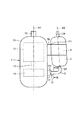
図1はこの発明の一実施形態の圧縮機の正面模式図である。 FIG. 1 is a schematic front view of a compressor according to an embodiment of the present invention.
上記圧縮機は、圧縮機本体1と、この圧縮機本体1の側方に配置されたアキュームレータ2と、アキュームレータ2内の冷媒ガスを圧縮機本体1内へ案内する出口管3と、圧縮機本体1にアキュームレータ2を固定するバンド部材4とを備える。この圧縮機は、例えば、図示しない凝縮器、膨張機構(例えば膨張弁)および蒸発器と共に、空気調和機の冷媒回路の主要部を構成する。
The compressor includes a
上記圧縮機本体1は、密閉容器11と、この密閉容器11内に配置されるモータ12と、密閉容器11内に配置されると共に、モータ12にシャフト13を介して接続される圧縮要素14とを有する。
The
上記密閉容器11は、圧縮機本体1の中心軸A1方向からみて円形の外周面を有する。なお、密閉容器11は、高圧ドーム型または低圧ドーム型の何れのタイプであってもよい。
The
また、上記密閉容器11の上部には吐出管15が接続されている。アキュームレータ2から圧縮機本体1内に流入した冷媒ガスは、圧縮要素14によって圧縮されて高温になった後、吐出管15を介して上記凝縮器へ送られる。
A
また、上記圧縮機本体1の側部のうちの上側の部分(上側部)には、支持台16が設けられている。この支持台16の上端にはアキュームレータ2の周面が点接触する。これにより、アキュームレータ2が水平方向において支持される。すなわち、支持台16の上端の一点が支持点P1となる。
A
また、上記圧縮機本体1の側部のうちの下側の部分(下側部)には吸入口17が設けられている。この吸入口17は支持台16の下方に位置する。すなわち、吸入口17は、鉛直方向において支持台16と重なるように設けられている。
Further, a
上記モータ12は、図示しないロータおよびステータを有し、このロータにシャフト13が固定される。
The
上記アキュームレータ2は、アキュームレータ2の中心軸A2の上側が、アキュームレータ2の中心軸A2の下側よりも圧縮機本体1に近づくように、圧縮機本体1の中心軸A1に対して傾いている。
The
上記出口管3は、アキュームレータ2の出口21と圧縮機本体1の吸入口17の間に配置され、一端部が圧縮機本体1の吸入口17に挿入されている。
The
上記バンド部材4は、アキュームレータ2の周面に巻回され、巻回方向の各端部が支持台16に取り付けられている。
The
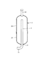
図2は上記アキュームレータ2の概略断面図である。
上記アキュームレータ2は、下面に、冷媒ガスを排出するための出口21を有する。より詳しくは、アキュームレータ2は、上容器22と、この上容器22に接続された下容器23とを有し、出口21が下容器23の下面に形成されている。また、アキュームレータ2は、入口管24を介して上記蒸発器に接続される。
FIG. 2 is a schematic sectional view of the
The
上記出口管3は、アキュームレータ2の出口21に挿通されている。この出口管3は、アキュームレータ2の内部で、アキュームレータ2の中心軸A2に沿うように延びている一方、アキュームレータ2の外部で、圧縮機本体1側に向かって屈曲している。
The
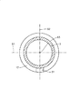
図3は図1のIII−III線矢視の断面模式図である。 3 is a schematic cross-sectional view taken along line III-III in FIG.
上記出口管3の上記一端部側(吸入口17側)の周面には、出口管3の上記一端部の中心軸A3を通る水平面S1よりも下側に位置するように、吸入口17の端面に当接する突起部31が設けられている。この突起部31は、出口管3の上記一端部の中心軸A3を通る鉛直面S2と交差する。
The
上記構成の圧縮機によれば、圧縮機本体1の吸入口17に出口管3の一端部を挿入したとき、突起部31が吸入口17の端面に当接するので、吸入口17に対する出口管3の過剰な挿入を容易に防ぐことができる。したがって、圧縮機本体1の吸入口17に対する出口管3の挿入量が所望量からずれるのを容易に防ぐことができる。
According to the compressor having the above-described configuration, when one end portion of the
また、上記圧縮機本体1の吸入口17に出口管3の一端部を挿入した後、アキュームレータ2を傾けて、支持台16の上端にアキュームレータ2の周面を点接触させるとき、水平面S1よりも下側に支点P2ができる。これにより、水平面S1よりも上側に支点ができるとき、この支点から支点P1までの支点間距離に比べて、支点P2から支点P1までの支点間距離が大きくなる。したがって、仮に、突起部31の位置がばらついたとしても、アキュームレータ2の取付角度(鉛直方向に対して中心軸A2がなす角度)が所望角度から大きくずれるのを防ぐことができる。
In addition, when one end portion of the
このように、上記アキュームレータ2の取付角度が所望角度から大きくずれるのを防ぐことができるので、アキュームレータ2の共振周波数の変化で運転音がばらつくのを容易に防ぐことができる。
As described above, since the mounting angle of the
また、上記圧縮機本体1の吸入口17に対する出口管3の挿入量が所望量からずれるのを容易に防ぐことができるので、運転音のばらつきを低減できる。
In addition, since the amount of insertion of the
仮に、上記水平面S1よりも上側に突起部があれば、水平面S1よりも上側に支点ができる。これにより、上記支点から支点P1までの支点間距離は、支点P2から支点P1までの支点間距離に比べて小さくなる。その結果、上記突起部の位置がばらつくと、アキュームレータ2の取付角度が所望角度から大きくずれてしまう。
If there is a protrusion on the upper side of the horizontal plane S1, a fulcrum is formed on the upper side of the horizontal plane S1. Thereby, the inter-fulcrum distance from the fulcrum to the fulcrum P1 is smaller than the inter-fulcrum distance from the fulcrum P2 to the fulcrum P1. As a result, if the position of the protrusion varies, the mounting angle of the
また、上記突起部31は、出口管3の一端部の中心軸A3を通る鉛直面S2と交差するので、支点間距離を十分に大きくとることができる。
Moreover, since the said
また、上記アキュームレータ2の周面が支持台16の上端に点接触するので、アキュームレータ2の取付位置が一定する。
Further, since the peripheral surface of the
上記実施形態では、アキュームレータ2の周面が支持台16の上端に点接触するようになっていたが、支持台16の形状を変更して、アキュームレータ2の周面が支持台16の上端に線接触するようにしてもよい。あるいは、支持台16の形状を変更して、アキュームレータ2の周面が支持台16に面接触するようにしてもよい。
In the above embodiment, the peripheral surface of the
上記実施形態では、出口管3の吸入口17側の周面に、出口管3の上記一端部の中心軸A3を通る水平面S1よりも下側に位置するように、吸入口17の端面に当接する突起部31を単数設けていたが、突起部31と同様の突起部を複数設けてもよい。
In the above embodiment, the end surface of the
上記実施形態では、突起部31は、軸方向から見た形状が矩形状であったが、円弧形状になるようにしてもよい。
In the embodiment described above, the
上記実施形態において、支持台16は、容器11と一体に形成されたブロック部であってもよいし、容器11に溶接で固定された板状部材であってもよい。
In the above-described embodiment, the
上記実施形態では、アキュームレータ2と圧縮機本体1の間に1本の出口管3を配置していたが、アキュームレータ2と圧縮機本体1の間に2本の出口管を配置する場合もある。この場合、2本の出口管のうち、下側の出口管が、突起部31と同様に設けられた突起部を、圧縮機本体1側の周面に有するようにしてもよい。
In the above embodiment, one
この発明の具体的な実施形態について説明したが、この発明は上記実施形態に限定されるものではなく、この発明の範囲内で種々変更して実施することができる。 Although specific embodiments of the present invention have been described, the present invention is not limited to the above-described embodiments, and various modifications can be made within the scope of the present invention.
1 圧縮機本体
2 アキュームレータ
3 出口管
17 吸入口
21 出口
31 突起部
A1,A2,A3 中心軸
S1 水平面
S2 鉛直面
DESCRIPTION OF
Claims (2)
上記支持台(16)に接触し、出口(21)を有するアキュームレータ(2)と、
上記出口(21)と上記吸入口(17)の間に配置され、一端部が上記吸入口(17)に挿入された出口管(3)と
を備え、
上記出口管(3)の上記一端部側の周面には、上記出口管(3)の上記一端部の中心軸(A3)を通る水平面(S1)よりも下側に位置するように、上記吸入口(17)の端面に当接する突起部(31)が設けられていることを特徴とする圧縮機。 A compressor body (1) provided with a support base (16) on the upper side and a suction port (17) on the lower side;
An accumulator (2) in contact with the support (16) and having an outlet (21);
An outlet pipe (3) disposed between the outlet (21) and the inlet (17) and having one end inserted into the inlet (17);
The peripheral surface of the outlet pipe (3) on the one end side is positioned below the horizontal plane (S1) passing through the central axis (A3) of the one end of the outlet pipe (3). A compressor characterized in that a protrusion (31) is provided in contact with the end face of the suction port (17).
上記突起部(31)は、上記出口管(3)の上記一端部の中心軸(A3)を通る鉛直面(S2)と交差することを特徴とする圧縮機。 The compressor according to claim 1,
The compressor characterized in that the protrusion (31) intersects a vertical plane (S2) passing through the central axis (A3) of the one end of the outlet pipe (3).
Priority Applications (1)
| Application Number | Priority Date | Filing Date | Title |
|---|---|---|---|
| JP2014139921A JP2016017444A (en) | 2014-07-07 | 2014-07-07 | Compressor |
Applications Claiming Priority (1)
| Application Number | Priority Date | Filing Date | Title |
|---|---|---|---|
| JP2014139921A JP2016017444A (en) | 2014-07-07 | 2014-07-07 | Compressor |
Publications (1)
| Publication Number | Publication Date |
|---|---|
| JP2016017444A true JP2016017444A (en) | 2016-02-01 |
Family
ID=55232850
Family Applications (1)
| Application Number | Title | Priority Date | Filing Date |
|---|---|---|---|
| JP2014139921A Pending JP2016017444A (en) | 2014-07-07 | 2014-07-07 | Compressor |
Country Status (1)
| Country | Link |
|---|---|
| JP (1) | JP2016017444A (en) |
Cited By (2)
| Publication number | Priority date | Publication date | Assignee | Title |
|---|---|---|---|---|
| CN106996664A (en) * | 2017-04-28 | 2017-08-01 | 广东美芝制冷设备有限公司 | The manufacture method of the reservoir of compressor, compressor and compressor |
| CN107387367A (en) * | 2017-08-24 | 2017-11-24 | 广东美的制冷设备有限公司 | Compressor and there is its refrigerating plant |
-
2014
- 2014-07-07 JP JP2014139921A patent/JP2016017444A/en active Pending
Cited By (2)
| Publication number | Priority date | Publication date | Assignee | Title |
|---|---|---|---|---|
| CN106996664A (en) * | 2017-04-28 | 2017-08-01 | 广东美芝制冷设备有限公司 | The manufacture method of the reservoir of compressor, compressor and compressor |
| CN107387367A (en) * | 2017-08-24 | 2017-11-24 | 广东美的制冷设备有限公司 | Compressor and there is its refrigerating plant |
Similar Documents
| Publication | Publication Date | Title |
|---|---|---|
| US11428239B2 (en) | Compressor suction pipe, compression unit, and chiller | |
| US20030077174A1 (en) | Multi-blade centrifugal fan | |
| US10054344B2 (en) | Expansion valve and refrigeration cycle apparatus | |
| JP2016084790A (en) | Compressor structure for turbocharger | |
| JP2016113922A5 (en) | ||
| CN205138016U (en) | Reservoir and have its compressor | |
| JP2016017444A (en) | Compressor | |
| JP6909376B2 (en) | Flow control valve and refrigeration cycle system | |
| JP6388715B2 (en) | Compressor | |
| JP2016079886A (en) | Compressor bracket and rotary compressor | |
| US11002292B2 (en) | Propeller fan and refrigeration cycle device | |
| CN105627474A (en) | Air conditioner | |
| WO2014057602A1 (en) | Compressor | |
| CN204113749U (en) | Gas fan and refrigerating circulatory device | |
| CN105317741A (en) | Drainage pump and air conditioner | |
| CN106224205B (en) | The muffler of compressor and there is its compressor | |
| KR102266827B1 (en) | An outdoor unit for a an air conditioner | |
| KR102265203B1 (en) | air conditioner out door unit | |
| CN207365542U (en) | The refrigeration system of refrigerator | |
| JP2012251437A (en) | Compressor | |
| CN110017545B (en) | Air conditioner | |
| WO2021208545A1 (en) | Check valve | |
| JP2017101714A (en) | Pipe fixing structure | |
| JP4293123B2 (en) | Compressor | |
| WO2021064984A1 (en) | Refrigeration cycle device |