JP2016014382A - Exhaust heat recovery device - Google Patents

Exhaust heat recovery device Download PDF

Info

Publication number
JP2016014382A
JP2016014382A JP2014137997A JP2014137997A JP2016014382A JP 2016014382 A JP2016014382 A JP 2016014382A JP 2014137997 A JP2014137997 A JP 2014137997A JP 2014137997 A JP2014137997 A JP 2014137997A JP 2016014382 A JP2016014382 A JP 2016014382A
Authority
JP
Japan
Prior art keywords
heat
exhaust
recovery device
heat recovery
heat medium
Prior art date
Legal status (The legal status is an assumption and is not a legal conclusion. Google has not performed a legal analysis and makes no representation as to the accuracy of the status listed.)
Pending
Application number
JP2014137997A
Other languages
Japanese (ja)
Inventor
史朗 中嶋
Shiro Nakajima
史朗 中嶋
出居 一博
Kazuhiro Idei
一博 出居
Current Assignee (The listed assignees may be inaccurate. Google has not performed a legal analysis and makes no representation or warranty as to the accuracy of the list.)
Marelli Corp
Original Assignee
Calsonic Kansei Corp
Priority date (The priority date is an assumption and is not a legal conclusion. Google has not performed a legal analysis and makes no representation as to the accuracy of the date listed.)
Filing date
Publication date
Application filed by Calsonic Kansei Corp filed Critical Calsonic Kansei Corp
Priority to JP2014137997A priority Critical patent/JP2016014382A/en
Publication of JP2016014382A publication Critical patent/JP2016014382A/en
Pending legal-status Critical Current

Links

Images

Classifications

    • YGENERAL TAGGING OF NEW TECHNOLOGICAL DEVELOPMENTS; GENERAL TAGGING OF CROSS-SECTIONAL TECHNOLOGIES SPANNING OVER SEVERAL SECTIONS OF THE IPC; TECHNICAL SUBJECTS COVERED BY FORMER USPC CROSS-REFERENCE ART COLLECTIONS [XRACs] AND DIGESTS
    • Y02TECHNOLOGIES OR APPLICATIONS FOR MITIGATION OR ADAPTATION AGAINST CLIMATE CHANGE
    • Y02TCLIMATE CHANGE MITIGATION TECHNOLOGIES RELATED TO TRANSPORTATION
    • Y02T10/00Road transport of goods or passengers
    • Y02T10/10Internal combustion engine [ICE] based vehicles
    • Y02T10/12Improving ICE efficiencies

Abstract

PROBLEM TO BE SOLVED: To provide an exhaust heat recovery device capable of preventing the leakage of a heat medium to outside of a heat medium flow passage by heat damage from an exhaust system.SOLUTION: An exhaust heat recovery device 100 comprises: a heat exchange unit 10 implementing heat exchange with exhaust gas discharged from an engine; a bypass unit 20 causing the exhaust gas to bypass the heat exchange unit 10; a valve 50 distributing the exhaust gas to the heat exchange unit 10 and the bypass unit 20; and a valve switchover mechanism 60 rotating the valve 50. The heat exchange unit 10 includes a heat medium flow passage 11 in which a heat medium for the heat exchange with the exhaust gas circulates. The valve switchover mechanism 60 includes a temperature sensor 61 disposed apart from the heat medium and responding to heat of the heat medium; and an actuator 62 rotating the valve 50 by the response of the temperature sensor 61.

Description

本発明はバルブ切替機構を備える排熱回収器に関するものである。   The present invention relates to an exhaust heat recovery device including a valve switching mechanism.

排熱回収器の熱媒体流路を循環する熱媒体の熱に応じて排熱回収器に設けられているバルブを回動させる排熱回収器のバルブ切替機構が特許文献1に開示されている。特許文献1の排熱回収器のバルブ切替機構には、熱媒体の熱により作動するアクチュエータが使われており、アクチュエータのエレメント内の熱膨張体が熱媒体の熱によって膨張収縮を行うことによりロッドが進退してバルブの切り替えを行う。   Patent Document 1 discloses a valve switching mechanism of an exhaust heat recovery device that rotates a valve provided in the exhaust heat recovery device according to the heat of the heat medium circulating in the heat medium flow path of the exhaust heat recovery device. . The valve switching mechanism of the exhaust heat recovery device of Patent Document 1 uses an actuator that is operated by the heat of the heat medium, and the thermal expansion body in the element of the actuator expands and contracts by the heat of the heat medium. Moves back and forth to switch valves.

特開2010−31669号公報JP 2010-31669 A

しかしながら、特許文献1に記載のバルブ切替機構では、アクチュエータのエレメントは、循環する熱媒体の熱に応答するために熱媒体流路内に設置され、ゴム製のOリングによるシールがされている。このため、排気系からの熱害によってシールが劣化又は破損することによって、熱媒体が熱媒体流路の外部へ漏れる問題がある。   However, in the valve switching mechanism described in Patent Document 1, the actuator element is installed in the heat medium flow path in order to respond to the heat of the circulating heat medium, and is sealed with a rubber O-ring. For this reason, there is a problem that the heat medium leaks to the outside of the heat medium flow path when the seal deteriorates or breaks due to heat damage from the exhaust system.

本発明はこのような問題を解決するために発明されたもので、排気系からの熱害によって熱媒体が熱媒体流路の外部へ漏れることのない排熱回収器を提供することを目的とする。   The present invention was invented to solve such problems, and an object thereof is to provide an exhaust heat recovery device in which the heat medium does not leak outside the heat medium flow path due to heat damage from the exhaust system. To do.

本発明のある態様に係る排熱回収器は、エンジンから排出された排気と熱交換を行う熱交換部と、排気を熱交換部からバイパスさせるバイパス部と、を備える。排熱回収器は、熱交換部とバイパス部とに排気を振り分けるバルブと、バルブを回動するバルブ切替機構と、を備える。熱交換部は、排気と熱交換を行うための熱媒体が循環する熱媒体流路を備える。バルブ切替機構は、熱媒体から離間して配置され、熱媒体の熱によって応答する熱応答部としての温度センサと、温度センサの応答によりバルブを回動させる作動部としてのアクチュエータと、を備える。   An exhaust heat recovery device according to an aspect of the present invention includes a heat exchange unit that exchanges heat with exhaust discharged from an engine, and a bypass unit that bypasses the exhaust from the heat exchange unit. The exhaust heat recovery device includes a valve that distributes the exhaust gas to the heat exchange unit and the bypass unit, and a valve switching mechanism that rotates the valve. The heat exchange unit includes a heat medium flow path through which a heat medium for exchanging heat with the exhaust gas circulates. The valve switching mechanism includes a temperature sensor serving as a heat response unit that is arranged apart from the heat medium and responds with heat from the heat medium, and an actuator serving as an operation unit that rotates the valve according to the response of the temperature sensor.

この態様によると、排熱回収器本体を循環する熱媒体流路内に直接、アクチュエータのエレメントを設置することがないので劣化又は破損する懸念のあるシールを用いる必要がなくなり、排気系からの熱害によって熱媒体が外部に漏れることをなくすことができる。   According to this aspect, since the actuator element is not directly installed in the heat medium flow path circulating through the exhaust heat recovery device body, there is no need to use a seal that may be deteriorated or damaged, and heat from the exhaust system is eliminated. The heat medium can be prevented from leaking outside due to harm.

本発明の第1実施形態の排熱回収器の斜視図である。It is a perspective view of the waste heat recovery device of a 1st embodiment of the present invention. 本発明のある態様に係る熱交換部に排気を導入する場合のバルブの状態を示す図である。It is a figure which shows the state of the valve | bulb in the case of introduce | transducing exhaust_gas | exhaustion into the heat exchange part which concerns on a certain aspect of this invention. 本発明のある態様に係るバイパス部に排気を導入する場合のバルブの状態を示す図である。It is a figure which shows the state of the valve | bulb when introducing exhaust_gas | exhaustion into the bypass part which concerns on a certain aspect of this invention. 第1実施形態の熱交換部の内部を側方から見たときの構造図である。It is a structure figure when the inside of the heat exchange part of 1st Embodiment is seen from the side. 図3AのIIIb−IIIb線に沿う横断面図である。3B is a cross-sectional view taken along line IIIb-IIIb in FIG. 3A. FIG. 本発明の第2実施形態の排熱回収器の斜視図である。It is a perspective view of the waste heat recovery device of a 2nd embodiment of the present invention. 第2実施形態のアクチュエータの内部を側方から見たときの構造図である。It is a structural diagram when the inside of the actuator of 2nd Embodiment is seen from the side. 図5AのVb−Vb線に沿う横断面図である。It is a cross-sectional view which follows the Vb-Vb line | wire of FIG. 5A. 第2実施形態のアクチュエータの内部構造の変形例である。It is a modification of the internal structure of the actuator of 2nd Embodiment. 図6AのVIb−VIb線に沿う横断面図である。FIG. 6B is a cross-sectional view taken along line VIb-VIb in FIG. 6A.

以下、図面を参照して、本発明の実施形態について説明する。   Embodiments of the present invention will be described below with reference to the drawings.

(第1実施形態)
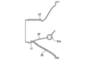
図1は、本実施形態の排熱回収器100の斜視図である。排熱回収器100は、排気と熱交換を行う熱交換部10と、熱交換せずにバイパスさせるバイパス部20と、排気導入部30と、排気排出部40と、を備える。また、排熱回収器100は、熱交換部10とバイパス部20とに排気を振り分けるバルブ50と、バルブ50を回動制御するバルブ切替機構60と、アクチュエータ62の動作を制御するコントローラ70と、を備える。熱交換部10及びバイパス部20の外周は、排熱回収器100の外壁部101によって囲われている。外壁部101は、熱伝達性がよくなるように薄い金属製の素材等で形成される。熱交換部10の外側に位置する外壁部101には、熱交換部10側に窪んだ凹部101aが形成されている。
(First embodiment)
FIG. 1 is a perspective view of the exhaust heat recovery device 100 of the present embodiment. The exhaust heat recovery device 100 includes a heat exchange unit 10 that exchanges heat with exhaust, a bypass unit 20 that bypasses without exchanging heat, an exhaust introduction unit 30, and an exhaust discharge unit 40. The exhaust heat recovery device 100 includes a valve 50 that distributes exhaust gas to the heat exchange unit 10 and the bypass unit 20, a valve switching mechanism 60 that controls the rotation of the valve 50, a controller 70 that controls the operation of the actuator 62, Is provided. The outer peripheries of the heat exchange unit 10 and the bypass unit 20 are surrounded by the outer wall 101 of the exhaust heat recovery unit 100. The outer wall portion 101 is formed of a thin metal material or the like so as to improve heat transferability. A concave portion 101 a that is recessed toward the heat exchange unit 10 is formed in the outer wall 101 that is located outside the heat exchange unit 10.

熱交換部10は、循環する熱媒体と流入した排気との間で熱交換を行う。熱交換部10は、熱交換部10内に熱媒体を流入させる排熱回収器入口流路11aと、熱交換部10外に熱媒体を流出させる排熱回収器出口流路11bと、を備える。熱媒体は、エンジン冷却水やエンジン冷却水とは独立したサイクルの冷却水であり、例えばLLCが使われる。熱交換によって温度が高くなった熱媒体は、車室内の暖房やエンジンの暖機などに利用される。   The heat exchange unit 10 performs heat exchange between the circulating heat medium and the exhaust gas that has flowed. The heat exchanging unit 10 includes an exhaust heat recovery device inlet channel 11 a that allows a heat medium to flow into the heat exchange unit 10, and an exhaust heat recovery device outlet channel 11 b that allows the heat medium to flow out of the heat exchange unit 10. . The heat medium is engine cooling water or cooling water having a cycle independent of engine cooling water, and for example, LLC is used. The heat medium whose temperature has been increased by heat exchange is used for heating the passenger compartment or warming up the engine.

バイパス部20は、熱交換部10と並列に配置される。流入した排気は、バイパス部20へとバイパスさせることで、熱交換部10で熱交換を行わずに排気排出部40へ流すことができる。   The bypass unit 20 is arranged in parallel with the heat exchange unit 10. The exhaust gas that has flowed in can be bypassed to the bypass unit 20, and can flow to the exhaust discharge unit 40 without performing heat exchange in the heat exchange unit 10.

排気導入部30は、熱交換部10とバイパス部20の上流に配置され、エンジンから排出される排気を排熱回収器100内に導入する入口である。排気導入部30から導入された排気は、熱交換部10又はバイパス部20を通過して排気排出部40へと流れる。   The exhaust introduction unit 30 is an inlet that is disposed upstream of the heat exchange unit 10 and the bypass unit 20 and introduces exhaust exhausted from the engine into the exhaust heat recovery unit 100. Exhaust gas introduced from the exhaust gas introduction unit 30 passes through the heat exchange unit 10 or the bypass unit 20 and flows to the exhaust gas discharge unit 40.

排気排出部40は、熱交換部10とバイパス部20の下流に配置され、熱交換部10又はバイパス部20を通過した排気を排熱回収器100の外に排出する出口である。   The exhaust exhaust unit 40 is an outlet that is disposed downstream of the heat exchange unit 10 and the bypass unit 20 and exhausts the exhaust gas that has passed through the heat exchange unit 10 or the bypass unit 20 to the outside of the exhaust heat recovery unit 100.

バルブ50は、排気導入部30に設置され、バルブ切替機構60の動作に応じて回動し、熱交換部10とバイパス部20とにエンジンから排出され流れてくる排気を振り分ける。図2A及び図2Bに示すように、バルブ50は、回転軸50aを回転中心にして回動することができる。排気導入部30には、バルブ50の回動を規制するストッパー51、2が形成されている。図2Aは熱交換部10に排気を導入する場合のバルブ50の状態を示す図であり、図2Bはバイパス部20に排気を導入する場合のバルブ50の状態を示す図である。排気を熱交換部10へと流入させる場合には、図2Aに示すようにバルブ50はストッパー51と当接し、バイパス部20への流路が遮断される。他方、排気をバイパス部20に流入させる場合には、図2Bに示すようにバルブ50はストッパー52と当接し、熱交換部10への流路が遮断される。   The valve 50 is installed in the exhaust introduction unit 30 and rotates according to the operation of the valve switching mechanism 60 to distribute the exhaust exhausted from the engine to the heat exchange unit 10 and the bypass unit 20. As shown in FIGS. 2A and 2B, the valve 50 can be rotated about a rotation shaft 50a. Stoppers 51 and 2 for restricting the rotation of the valve 50 are formed in the exhaust introduction part 30. FIG. 2A is a diagram illustrating a state of the valve 50 when exhaust is introduced into the heat exchange unit 10, and FIG. 2B is a diagram illustrating a state of the valve 50 when exhaust is introduced into the bypass unit 20. When the exhaust gas is allowed to flow into the heat exchanging unit 10, the valve 50 comes into contact with the stopper 51 and the flow path to the bypass unit 20 is blocked as shown in FIG. 2A. On the other hand, when the exhaust gas is caused to flow into the bypass unit 20, the valve 50 comes into contact with the stopper 52 as shown in FIG. 2B, and the flow path to the heat exchange unit 10 is blocked.

図1に戻って、バルブ切替機構60は、外壁部101の凹部101aに設置される温度センサ61と、バルブ50に取り付けられるアクチュエータ62と、を備える。   Returning to FIG. 1, the valve switching mechanism 60 includes a temperature sensor 61 installed in the recess 101 a of the outer wall 101 and an actuator 62 attached to the valve 50.

温度センサ61は、外壁部101の凹部101aを介して熱媒体の温度を測るセンサである。例えば温度センサ61には、サーミスタや熱電対、白金測温抵抗体が用いられる。   The temperature sensor 61 is a sensor that measures the temperature of the heat medium via the concave portion 101 a of the outer wall portion 101. For example, the temperature sensor 61 is a thermistor, a thermocouple, or a platinum resistance thermometer.

アクチュエータ62は、バルブ50を回動する装置であって、例えば油圧や空圧、電力によって作動する。   The actuator 62 is a device that rotates the valve 50 and is operated by, for example, hydraulic pressure, pneumatic pressure, or electric power.

コントローラ70は、中央演算装置(CPU)、読み出し専用メモリ(ROM)、ランダムアクセスメモリ(RAM)及び入出力インターフェイス(I/Oインターフェイス)を備えたマイクロコンピュータで構成される。コントローラ70には、熱媒体の熱によって応答する温度センサ61からの応答信号が入力される。そして、コントローラ70は、当該応答信号に基づいて、アクチュエータ62の作動可否を判断する。   The controller 70 is configured by a microcomputer including a central processing unit (CPU), a read only memory (ROM), a random access memory (RAM), and an input / output interface (I / O interface). A response signal from the temperature sensor 61 that responds to the heat of the heat medium is input to the controller 70. Then, the controller 70 determines whether or not the actuator 62 is operable based on the response signal.

ここで、図3A及び図3Bを参照し、熱交換部10の内部構造及びバルブ切替機構60について説明する。図3Aは熱交換部10の内部を側方から見たときの構造図であり、図3Bは図3AのIIIb−IIIb線に沿う横断面図である。   Here, the internal structure of the heat exchange unit 10 and the valve switching mechanism 60 will be described with reference to FIGS. 3A and 3B. FIG. 3A is a structural view when the inside of the heat exchange unit 10 is viewed from the side, and FIG. 3B is a cross-sectional view taken along line IIIb-IIIb in FIG. 3A.

図3Aに示すように、熱交換部10の内部には、熱媒体の循環する熱媒体流路11と、排気の流れる排気通路12と、が形成されている。   As shown in FIG. 3A, a heat medium flow path 11 through which a heat medium circulates and an exhaust passage 12 through which exhaust gas flows are formed inside the heat exchange unit 10.

熱媒体流路11は、図1に示す排熱回収器入口流路11aから導入された熱媒体を熱交換部10内で循環させる。熱媒体は、熱媒体流路11を循環後に排熱回収器出口流路11bから排出される。排熱回収器出口流路11bは、図3Aに示すように外壁部101及び排気通路12を貫通して排熱回収器100の外部へと接続されている。   The heat medium flow channel 11 circulates the heat medium introduced from the exhaust heat recovery device inlet flow channel 11a shown in FIG. The heat medium is discharged from the exhaust heat recovery device outlet flow path 11b after circulating through the heat medium flow path 11. As shown in FIG. 3A, the exhaust heat recovery device outlet channel 11 b passes through the outer wall portion 101 and the exhaust passage 12 and is connected to the outside of the exhaust heat recovery device 100.

排気通路12は、熱交換部10内に流入した排気が流れる通路である。熱交換部10内に流入した排気は、熱媒体流路11を循環する熱媒体と熱交換を行い、熱交換後の排気は排気排出部40へと流される。排気通路12は、熱媒体流路11間に、又は外壁部101と熱媒体流路11との間に形成される。または、外壁部101と熱媒体流路11との間に形成される排気通路12は、外壁部101に形成された凹部101aの底部が熱媒体流路11と当接することによって、一部が閉塞されている。凹部101aの側部は、排気の流れに抵抗を与えないように排気通路12に対して斜めに形成されている。   The exhaust passage 12 is a passage through which the exhaust gas flowing into the heat exchange unit 10 flows. The exhaust gas flowing into the heat exchange unit 10 exchanges heat with the heat medium circulating in the heat medium channel 11, and the exhaust gas after the heat exchange flows to the exhaust gas discharge unit 40. The exhaust passage 12 is formed between the heat medium flow paths 11 or between the outer wall portion 101 and the heat medium flow path 11. Alternatively, the exhaust passage 12 formed between the outer wall portion 101 and the heat medium passage 11 is partially blocked by the bottom portion of the recess 101 a formed in the outer wall portion 101 being in contact with the heat medium passage 11. Has been. The side of the recess 101a is formed obliquely with respect to the exhaust passage 12 so as not to give resistance to the exhaust flow.

このように、排気通路12の一部を閉塞する凹部101aは、排熱回収器出口流路11b付近の外壁部101に形成される。凹部101aと排熱回収器出口流路11bは、図3A及び図3Bに示すように排気通路12内の排気の流れる方向に並ぶように配置される。図3A及び図3Bの矢印は、排気通路12を流れる排気の流れを図示したものである。凹部101aは、排熱回収器出口流路11bよりも排気通路12の上流側に位置する。凹部101aは、排気の流れに抵抗を与えないよう、上流側に角部が臨む三角形状に形成されている。凹部101aを三角形状とすることで、排気の流れをガイドできるので下流側に位置する排熱回収器出口流路11bが排気と干渉することを抑制できる。   Thus, the recessed part 101a which obstruct | occludes a part of exhaust passage 12 is formed in the outer wall part 101 vicinity of the exhaust heat recovery device exit flow path 11b. The recess 101a and the exhaust heat recovery device outlet channel 11b are arranged so as to be aligned in the direction in which the exhaust gas flows in the exhaust passage 12, as shown in FIGS. 3A and 3B. The arrows in FIGS. 3A and 3B illustrate the flow of exhaust flowing through the exhaust passage 12. The recess 101a is located on the upstream side of the exhaust passage 12 with respect to the exhaust heat recovery device outlet channel 11b. The recess 101a is formed in a triangular shape with a corner facing the upstream side so as not to give resistance to the flow of exhaust. By making the recess 101a triangular, it is possible to guide the flow of exhaust gas, so that it is possible to suppress the exhaust heat recovery device outlet flow channel 11b located on the downstream side from interfering with the exhaust gas.

凹部101aの底部の外側には、温度センサ61が設置される。温度センサ61と凹部101aの側部との間に形成される隙間は、所定の距離ΔS以上になる。距離ΔSは、凹部101aの側部の内側を流れる排気の熱影響によって温度センサ61が誤作動しない距離に設定される。温度センサ61には、凹部101aの底部のみを介して熱媒体流路11を流れる熱媒体の熱が伝達される。なお、図3Bに示すように凹部101aは、温度センサ61の設置面積と距離ΔSを確保しやすいよう、やや丸みを帯びた形状とすることが好ましい。   A temperature sensor 61 is installed outside the bottom of the recess 101a. A gap formed between the temperature sensor 61 and the side portion of the recess 101a is a predetermined distance ΔS or more. The distance ΔS is set to a distance at which the temperature sensor 61 does not malfunction due to the heat effect of the exhaust flowing inside the side portion of the recess 101a. The heat of the heat medium flowing through the heat medium flow path 11 is transmitted to the temperature sensor 61 only through the bottom of the recess 101a. As shown in FIG. 3B, it is preferable that the recess 101a has a slightly rounded shape so that the installation area of the temperature sensor 61 and the distance ΔS can be easily secured.

上記した第1実施形態による排熱回収器100によれば、以下の効果を得ることができる。   According to the exhaust heat recovery device 100 according to the first embodiment described above, the following effects can be obtained.

本実施形態による排熱回収器100は、エンジンから排出された排気と熱交換を行う熱交換部10と、排気を熱交換部10からバイパスさせるバイパス部20と、を備える。また、排熱回収器100は、熱交換部10とバイパス部20とに排気を振り分けるバルブ50と、バルブ50を回動するバルブ切替機構60と、を備える。熱交換部10は、排気と熱交換を行うための熱媒体が循環する熱媒体流路11を備える。バルブ切替機構60は、熱媒体から離間して配置され、熱媒体の熱によって応答する熱応答部としての温度センサ61と、温度センサ61の応答によりバルブ50を回動させる作動部としてのアクチュエータ62と、を備える。   The exhaust heat recovery device 100 according to the present embodiment includes a heat exchanging unit 10 that exchanges heat with the exhaust discharged from the engine, and a bypass unit 20 that bypasses the exhaust from the heat exchanging unit 10. The exhaust heat recovery device 100 includes a valve 50 that distributes exhaust gas to the heat exchange unit 10 and the bypass unit 20, and a valve switching mechanism 60 that rotates the valve 50. The heat exchange unit 10 includes a heat medium flow path 11 through which a heat medium for exchanging heat with the exhaust gas circulates. The valve switching mechanism 60 is disposed away from the heat medium, and a temperature sensor 61 serving as a heat response unit that responds by the heat of the heat medium, and an actuator 62 serving as an operation unit that rotates the valve 50 according to the response of the temperature sensor 61. And comprising.

このような構成とすることで、温度センサ61は、熱媒体流路11を循環する熱媒体から離間し独立して配置されるので、熱媒体と接触することがなくなる。このため、温度センサ61と熱媒体とが接触する部分に、熱害によって劣化又は破損する懸念のあるシールを設ける必要がなくなり、熱媒体が外部に漏れることをなくすことができる。   By adopting such a configuration, the temperature sensor 61 is disposed separately from the heat medium circulating in the heat medium flow path 11 and thus is not in contact with the heat medium. For this reason, it is not necessary to provide a seal that may be deteriorated or broken due to heat damage at a portion where the temperature sensor 61 and the heat medium are in contact with each other, and the heat medium can be prevented from leaking to the outside.

本実施形態による排熱回収器100は、熱交換部10の外周に形成される外壁部101を備える。また、外壁部101には、バルブ切替機構60の温度センサ61が当接設置される。   The exhaust heat recovery device 100 according to the present embodiment includes an outer wall portion 101 formed on the outer periphery of the heat exchange portion 10. Further, the temperature sensor 61 of the valve switching mechanism 60 is placed in contact with the outer wall portion 101.

このような構成とすることで、温度センサ61は、外壁部101を介して外壁部101内側の熱媒体流路11を循環する熱媒体の熱に的確に応答することができる。   With such a configuration, the temperature sensor 61 can accurately respond to the heat of the heat medium circulating in the heat medium flow path 11 inside the outer wall 101 via the outer wall 101.

本実施形態による排熱回収器100では、熱交換部10は、外壁部101と熱媒体流路11との間に排気通路12を備える。また、本実施形態の排熱回収器100では、外壁部101には、排気通路12側に窪んで熱媒体流路11と当接する凹部101aが形成される。凹部101aには、凹部101aの側部から所定の隙間として距離ΔS以上を空けて温度センサ61が設置される。   In the exhaust heat recovery device 100 according to the present embodiment, the heat exchanging unit 10 includes an exhaust passage 12 between the outer wall portion 101 and the heat medium passage 11. Further, in the exhaust heat recovery device 100 of the present embodiment, the outer wall portion 101 is formed with a recess 101 a that is recessed toward the exhaust passage 12 and comes into contact with the heat medium passage 11. In the recess 101a, the temperature sensor 61 is installed with a distance ΔS or more as a predetermined gap from the side of the recess 101a.

このように、温度センサ61は、熱媒体流路11と当接する凹部101aに設置されるので、凹部101aの底部のみを介して熱媒体流路11を流れる熱媒体の熱に応答することができる。また、温度センサ61は、凹部101aの側部から距離ΔS以上を空けて温度センサ61が設置されるので、凹部101aの側部の内側を流れる排気の熱影響によって温度センサ61が誤作動することを防止できる。   Thus, since the temperature sensor 61 is installed in the recess 101a that contacts the heat medium flow path 11, it can respond to the heat of the heat medium flowing through the heat medium flow path 11 only through the bottom of the recess 101a. . Further, since the temperature sensor 61 is installed at a distance ΔS or more from the side of the recess 101a, the temperature sensor 61 malfunctions due to the heat effect of the exhaust gas flowing inside the side of the recess 101a. Can be prevented.

本実施形態による排熱回収器100は、熱媒体流路11には、排熱回収器100内を循環した熱媒体を外部に流出させる排熱回収器出口流路11bが排気通路12を貫通するように形成される。また、外壁部101の凹部101aは、排熱回収器出口流路11bの近傍に形成され、凹部101aと排熱回収器出口流路11bは、排気通路12内の排気の流れる方向に並ぶように配置される。   In the exhaust heat recovery device 100 according to the present embodiment, an exhaust heat recovery device outlet flow channel 11 b through which the heat medium circulated in the exhaust heat recovery device 100 flows out to the heat medium flow channel 11 passes through the exhaust passage 12. Formed as follows. Further, the concave portion 101a of the outer wall portion 101 is formed in the vicinity of the exhaust heat recovery device outlet flow path 11b, and the concave portion 101a and the exhaust heat recovery device outlet flow channel 11b are arranged in the exhaust flow direction in the exhaust passage 12. Be placed.

このような構成とすることで、凹部101aと排熱回収器出口流路11bがばらばらに配置されたときと比べて排気の流れを妨げにくいので、排気を効率よく流すことができる。また、温度センサ61は、排熱回収器出口流路11bの近傍に形成されるので、熱交換後の熱媒体の熱に的確に応答することができる。このため、熱媒体を適切な温度に制御できるので、熱媒体が熱くなり過ぎて沸騰することを抑制できる。   By setting it as such a structure, compared with the case where the recessed part 101a and the exhaust heat recovery device exit flow path 11b are arrange | positioned separately, it is hard to prevent the flow of exhaust gas, Therefore Exhaust gas can be flowed efficiently. Moreover, since the temperature sensor 61 is formed in the vicinity of the exhaust heat recovery device outlet channel 11b, it can accurately respond to the heat of the heat medium after heat exchange. For this reason, since a heat medium can be controlled to suitable temperature, it can suppress that a heat medium becomes too hot and boils.

なお、温度センサ61は、熱媒体の熱が伝達される外壁部101の凹部101aの底部の温度が測定できればよく、凹部101aから離間して設置されることとしてもよい。例えば、凹部101aから離間して設置される温度センサ61には、放射温度計が用いられる。   The temperature sensor 61 only needs to be able to measure the temperature of the bottom of the recess 101a of the outer wall 101 to which the heat of the heat medium is transmitted, and may be installed apart from the recess 101a. For example, a radiation thermometer is used for the temperature sensor 61 installed away from the recess 101a.

(第2実施形態)
図4を参照して、本発明の第2実施形態の排熱回収器100について説明する。
(Second Embodiment)
With reference to FIG. 4, the exhaust heat recovery device 100 of 2nd Embodiment of this invention is demonstrated.

第2実施形態による排熱回収器100では、熱交換部10及びバルブ切替機構60の構成が第1実施形態とは相違する。なお、以下の実施形態では第1実施形態と同じ機能を果たす構成には同一の符号を用い、重複する記載を適宜省略して説明する。   In the exhaust heat recovery device 100 according to the second embodiment, the configurations of the heat exchange unit 10 and the valve switching mechanism 60 are different from those of the first embodiment. In the following embodiments, the same functions as those in the first embodiment are denoted by the same reference numerals, and repeated description will be omitted as appropriate.

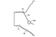
第2実施形態による排熱回収器100では、図4に示すように、排熱回収器100には、バルブ切替機構60のアクチュエータ62が熱交換部10の外側に位置する外壁部101に直接取り付けられている。外壁部101の内側には、熱媒体の流れる熱媒体流路11が形成されている。   In the exhaust heat recovery device 100 according to the second embodiment, as shown in FIG. 4, the actuator 62 of the valve switching mechanism 60 is directly attached to the outer wall portion 101 located outside the heat exchange unit 10 in the exhaust heat recovery device 100. It has been. A heat medium passage 11 through which a heat medium flows is formed inside the outer wall portion 101.

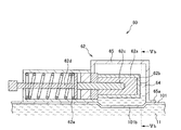
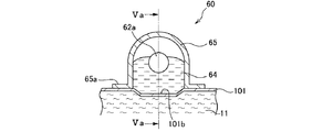
ここで、図5A及び図5Bを参照し、バルブ切替機構60の構造について説明する。図5Aは、アクチュエータ62の内部を側方から見たときの構造図である。図5Bは、図5AのVb−Vb線に沿う横断面図である。なお、図5Aは、図5BのVa−Va線に沿う断面を示している。   Here, the structure of the valve switching mechanism 60 will be described with reference to FIGS. 5A and 5B. FIG. 5A is a structural diagram when the inside of the actuator 62 is viewed from the side. FIG. 5B is a cross-sectional view taken along line Vb-Vb in FIG. 5A. 5A shows a cross section taken along the line Va-Va in FIG. 5B.

図5A及ぶ図5Bに示すように、バルブ切替機構60は、バルブ50を回動するアクチュエータ62と、アクチュエータ62に熱媒体の熱を伝達するグリス64と、グリス64を内側に封入するケース65と、を備える。   5A and 5B, the valve switching mechanism 60 includes an actuator 62 that rotates the valve 50, a grease 64 that transmits heat of the heat medium to the actuator 62, and a case 65 that encloses the grease 64 inside. .

アクチュエータ62は、熱交換部10の外側に位置する排熱回収器100の外壁部101に取り付けられる。アクチュエータ62は、エレメント62aと、ロッド62dと、非線形バネ62eと、熱膨張体62bと、ピストン62cと、備える。アクチュエータ62の一端は、バルブ50と連結される。   The actuator 62 is attached to the outer wall 101 of the exhaust heat recovery device 100 located outside the heat exchange unit 10. The actuator 62 includes an element 62a, a rod 62d, a non-linear spring 62e, a thermal expansion body 62b, and a piston 62c. One end of the actuator 62 is connected to the valve 50.

エレメント62aは、アクチュエータ62の他端側、すなわちバルブ50と反対側に形成される。エレメント62aの内部には、ピストン62cが進退可能となるように挿入されている。また、エレメント62aの内部は、ピストン62c以外の空間を埋めるように熱膨張体62bが充填されている。   The element 62 a is formed on the other end side of the actuator 62, that is, on the side opposite to the valve 50. A piston 62c is inserted into the element 62a so as to be able to advance and retract. The element 62a is filled with a thermal expansion body 62b so as to fill a space other than the piston 62c.

熱膨張体62bは、温度の低いときには固体であり、温度が高くなると融解して膨張する素材が用いられる。熱膨張体62bは、アクチュエータ62のエレメント62aを介して伝達される熱媒体の熱によって膨張収縮を行う熱応答部として機能する。   The thermal expansion body 62b is solid when the temperature is low, and a material that melts and expands when the temperature becomes high is used. The thermal expansion body 62 b functions as a thermal response unit that expands and contracts by the heat of the heat medium transmitted through the element 62 a of the actuator 62.

ピストン62cは、熱膨張体62bの膨張収縮により進退する。ピストン62cは、熱膨張体62bが膨張することによって、エレメント62a内の初期位置から押し出され、バルブ50方向に前進する。ピストン62cのバルブ50側の端部にはロッド62dが当接配置される。   The piston 62c advances and retreats due to the expansion and contraction of the thermal expansion body 62b. The piston 62c is pushed out from the initial position in the element 62a by the expansion of the thermal expansion body 62b, and moves forward in the valve 50 direction. A rod 62d is disposed in contact with the end of the piston 62c on the valve 50 side.

ロッド62dは、一方の端部をピストン62cに押し出されることでバルブ50の方向に進む。ロッド62dは、他方の端部がバルブ50と連結されており、進退によってバルブ50を回動させる。ロッド62dには、非線形バネ62eが取り付けられている。このように、ロッド62dは、バルブ50を回動させる作動部として機能する。   The rod 62d advances in the direction of the valve 50 by pushing one end of the rod 62d toward the piston 62c. The other end of the rod 62d is connected to the valve 50, and the valve 50 is rotated by advancing and retreating. A nonlinear spring 62e is attached to the rod 62d. In this manner, the rod 62d functions as an operating unit that rotates the valve 50.

非線形バネ62eは、ロッド62dをピストン62c側に向けて付勢する。したがって、ピストン62cは、ロッド62dを介して非線形バネ62eに付勢されているので、熱膨張体62bが収縮したときにエレメント62a内の初期位置へ戻ることができる。   The nonlinear spring 62e biases the rod 62d toward the piston 62c. Therefore, since the piston 62c is biased by the nonlinear spring 62e via the rod 62d, it can return to the initial position in the element 62a when the thermal expansion body 62b contracts.

エレメント62aの外側には、エレメント62aと熱交換が行えるようにグリス64が配置される。グリス64は、熱伝導性がよく、150℃から200℃の環境下でも安定した性能を発揮できる高耐熱性のものが使用される。なお、熱伝導性がよく高耐熱性の部材として、例えば銅メッシュを用いてもよい。   A grease 64 is disposed outside the element 62a so that heat exchange with the element 62a can be performed. As the grease 64, a material having high heat conductivity and high heat resistance capable of exhibiting stable performance even in an environment of 150 ° C. to 200 ° C. is used. For example, a copper mesh may be used as a member having high thermal conductivity and high heat resistance.

ケース65は、断熱構造の素材によって形成され、エレメント62aの回りに形成される。ケース65とエレメント62aとの間には、空間が形成される。ケース65には、断熱構造のものが用いられ、例えば内部が二重管構造となったものが用いられる。ケース65は、外壁部101と当接する部分にフランジ65aを有する。ケース65のフランジ65aは、溶接又は加締め等によって外壁部101に接合固定される。フランジ65aが外壁部101に接合固定されることによってケース65は密閉され、ケース65内の密閉された空間にグリス64とエレメント62aは封入される。   The case 65 is formed of a heat insulating material and is formed around the element 62a. A space is formed between the case 65 and the element 62a. For the case 65, a heat insulating structure is used, for example, one having a double tube structure inside. The case 65 has a flange 65 a at a portion that comes into contact with the outer wall portion 101. The flange 65a of the case 65 is joined and fixed to the outer wall 101 by welding or caulking. When the flange 65a is joined and fixed to the outer wall portion 101, the case 65 is sealed, and the grease 64 and the element 62a are enclosed in a sealed space in the case 65.

このように、熱膨張体62bと熱媒体流路11の熱媒体との間には、熱伝達性のよい外壁部101とグリス64とエレメント62aとが配置される。したがって、熱膨張体62bは、外壁部101とグリス64とエレメント62aとを介して伝達される熱媒体の熱によって応答し膨張収縮する。グリス64と接触する外壁部101には、熱媒体流路11の熱媒体の流れを局所的に速くして熱伝達効率が高くなるようにディンプル101bが設けられる。   Thus, between the thermal expansion body 62b and the heat medium of the heat medium flow path 11, the outer wall portion 101, the grease 64, and the element 62a having good heat transfer properties are disposed. Accordingly, the thermal expansion body 62b expands and contracts in response to the heat of the heat medium transmitted through the outer wall portion 101, the grease 64, and the element 62a. A dimple 101b is provided on the outer wall portion 101 in contact with the grease 64 so as to increase the heat transfer efficiency by locally accelerating the flow of the heat medium in the heat medium flow path 11.

熱媒体流路11の熱媒体の温度が低い場合には、エレメント62a内の熱膨張体62bは固定となっており、ロッド62dが非線形バネ62eによって付勢されることで、ピストン62cは初期位置に保持される。熱媒体の温度が低い場合は、例えばエンジンが暖機されておらず、排気の温度が低い場合が挙げられる。ピストン62cが初期位置に保持されているとき、バルブ50は、図2Aに示すようにストッパー51に当接してバイパス部20を閉塞する。このため、排気導入部30に導入された排気は、熱交換部10へと流れる。   When the temperature of the heat medium in the heat medium flow path 11 is low, the thermal expansion body 62b in the element 62a is fixed, and the rod 62d is biased by the nonlinear spring 62e, so that the piston 62c is in the initial position. Retained. When the temperature of the heat medium is low, for example, the engine is not warmed up and the temperature of the exhaust gas is low. When the piston 62c is held at the initial position, the valve 50 abuts against the stopper 51 and closes the bypass portion 20 as shown in FIG. 2A. For this reason, the exhaust gas introduced into the exhaust gas introduction unit 30 flows to the heat exchange unit 10.

排気の温度が高くなり、熱媒体流路11の熱媒体の温度が高くなると、伝達される熱媒体の熱によってエレメント62a内の熱膨張体62bが融解して膨張してピストン62cを押し出すので、ロッド62dは非線形バネ62eの反力に抗して前進する。バルブ50は、図2Bに示すようにストッパー52に当接する位置まで回動する。このため、排気導入部30に導入された排気は、バイパス部20へと流れる。このように、排気がバイパス部20に流れることで、熱交換部10で熱媒体と排気との熱交換が行われなくなるので、熱媒体の温度が高くなり過ぎることを抑制できる。   When the temperature of the exhaust gas becomes higher and the temperature of the heat medium in the heat medium flow path 11 becomes higher, the heat expansion body 62b in the element 62a is melted and expanded by the heat of the transmitted heat medium, and pushes out the piston 62c. The rod 62d moves forward against the reaction force of the nonlinear spring 62e. The valve 50 rotates to a position where it comes into contact with the stopper 52 as shown in FIG. 2B. For this reason, the exhaust gas introduced into the exhaust gas introduction unit 30 flows to the bypass unit 20. As described above, since the exhaust gas flows into the bypass unit 20, heat exchange between the heat medium and the exhaust gas is not performed in the heat exchanging unit 10, so that the temperature of the heat medium can be suppressed from becoming too high.

その後、熱媒体の温度が低下することによって、熱膨張体62bが凝固し収縮すると、非線形バネ62eの反力によってロッド62dは後退して、ピストン62cは初期位置に戻る。この結果、バルブ50は図2Aに示すように再びストッパー51と当接する位置まで回動するので、バイパス部20への流路は閉塞して、排気は熱交換部10に流れる。   Thereafter, when the temperature of the heat medium is lowered and the thermal expansion body 62b is solidified and contracted, the rod 62d is retracted by the reaction force of the nonlinear spring 62e, and the piston 62c is returned to the initial position. As a result, as shown in FIG. 2A, the valve 50 rotates again to a position where it comes into contact with the stopper 51, so that the flow path to the bypass unit 20 is closed and the exhaust gas flows to the heat exchange unit 10.

上記した第2実施形態による排熱回収器100によれば、以下の効果を得ることができる。   According to the exhaust heat recovery device 100 according to the second embodiment described above, the following effects can be obtained.

本実施形態による排熱回収器100では、バルブ切替機構60は、アクチュエータ62を備える。アクチュエータ62は、熱媒体の熱によって膨張収縮を行うことで熱応答部として機能する熱膨張体62bと、熱膨張体62bの膨張収縮により進退することで作動部として機能するロッド62dと、を備える。また、アクチュエータ62は、内部に熱膨張体62bとロッド62dを充填され、熱膨張体62bに熱媒体の熱を伝達するエレメント62aを備える。   In the exhaust heat recovery device 100 according to the present embodiment, the valve switching mechanism 60 includes an actuator 62. The actuator 62 includes a thermal expansion body 62b that functions as a thermal response unit by performing expansion and contraction by the heat of the heat medium, and a rod 62d that functions as an operation unit by moving forward and backward by the expansion and contraction of the thermal expansion body 62b. . The actuator 62 includes an element 62a that is filled with a thermal expansion body 62b and a rod 62d and that transmits heat of the heat medium to the thermal expansion body 62b.

このような構成とすることで、熱媒体の熱によって熱膨張体62bが膨張収縮してロッド62dを進退させるので、バルブ切替機構60は、熱媒体の熱に応じて的確にバルブ50を回動することができる。   With such a configuration, the thermal expansion body 62b expands and contracts due to the heat of the heat medium and moves the rod 62d forward and backward, so that the valve switching mechanism 60 rotates the valve 50 accurately according to the heat of the heat medium. can do.

本実施形態による排熱回収器100では、バルブ切替機構60は、エレメント62aの外側に配置され、熱媒体の熱を伝達する熱伝達体としてのグリス64を備える。グリス64は、エレメント62aを介して熱媒体の熱を熱膨張体62bへと伝達する。   In the exhaust heat recovery device 100 according to the present embodiment, the valve switching mechanism 60 includes a grease 64 that is disposed outside the element 62a and serves as a heat transfer body that transfers the heat of the heat medium. The grease 64 transfers the heat of the heat medium to the thermal expansion body 62b via the element 62a.

このような構成とすることで、エレメント62aを熱媒体流路11内に設けなくても、熱膨張体62bは、グリス64を介して伝達される熱媒体の熱によって膨張収縮を行うことができる。このため、エレメント62aと熱媒体流路11との接触部に熱害によって劣化又は破損する懸念のあるシールを用いる必要がなくなり、熱媒体が外部に漏れることをなくすことができる。   With such a configuration, the thermal expansion body 62b can be expanded and contracted by the heat of the heat medium transmitted through the grease 64 without providing the element 62a in the heat medium flow path 11. . For this reason, it is not necessary to use a seal that may be deteriorated or broken due to heat damage at the contact portion between the element 62a and the heat medium flow path 11, and the heat medium can be prevented from leaking to the outside.

本実施形態による排熱回収器100は、排熱回収器100との間で密閉空間を形成する断熱構造のケース65を備える。熱伝達体としてのグリス64とエレメント62aは、排熱回収器100とケース65との間の密閉空間内に封入される。   The exhaust heat recovery device 100 according to the present embodiment includes a case 65 having a heat insulating structure that forms a sealed space with the exhaust heat recovery device 100. The grease 64 and the element 62a as a heat transfer body are enclosed in a sealed space between the exhaust heat recovery device 100 and the case 65.

このような構成とすることで、断熱構造のケース65によって熱膨張体62bは周囲から断熱されるので、排熱回収器100周囲の熱影響によってアクチュエータ62が誤作動することを防止できる。また、密閉空間内に封入されたグリス64とエレメント62aが排熱回収器100の外壁部101を介して熱媒体流路11の熱媒体の熱を熱膨張体62bに伝達するので、熱膨張体62bと熱媒体との間で的確に熱交換を行うことができる。   By adopting such a configuration, the thermal expansion body 62b is thermally insulated from the surroundings by the case 65 having a heat insulating structure, so that the actuator 62 can be prevented from malfunctioning due to the thermal influence around the exhaust heat recovery device 100. Further, since the grease 64 and the element 62a enclosed in the sealed space transmit the heat of the heat medium in the heat medium flow path 11 to the thermal expansion body 62b via the outer wall portion 101 of the exhaust heat recovery device 100, the thermal expansion body Heat exchange can be accurately performed between 62b and the heat medium.

本実施形態による排熱回収器100では、ケース65は、アクチュエータ62及び排熱回収器100に接合される。   In the exhaust heat recovery device 100 according to the present embodiment, the case 65 is joined to the actuator 62 and the exhaust heat recovery device 100.

このような構成とすることで、遮蔽板等の追加部品を用いずにケース65をアクチュエータ62及び排熱回収器100の外壁部101上に設置することができるので、排熱回収器100の部品点数を削減することができる。また、ケース65は、接合によって固定されるので、熱害によって劣化又は破損する懸念をなくすことができる。   With this configuration, the case 65 can be installed on the outer wall 101 of the actuator 62 and the exhaust heat recovery device 100 without using additional components such as a shielding plate. The score can be reduced. Moreover, since the case 65 is fixed by joining, it is possible to eliminate the concern of deterioration or damage due to heat damage.

なお、本実施形態では、外壁部101の内側には熱媒体の流れる熱媒体流路11が形成されているが、例えば外壁部101の内側には排気の流れる排気通路12が形成されていてもよい。この場合には、エレメント62a内の熱膨張体62bが排気通路12を流れる排気の熱によって膨張収縮することで、ロッド62dが進退して、バルブ50を回動させることができる。   In the present embodiment, the heat medium flow path 11 through which the heat medium flows is formed inside the outer wall portion 101. However, for example, even if the exhaust passage 12 through which exhaust gas flows is formed inside the outer wall portion 101, Good. In this case, the thermal expansion body 62b in the element 62a expands and contracts by the heat of the exhaust gas flowing through the exhaust passage 12, whereby the rod 62d advances and retreats, and the valve 50 can be rotated.

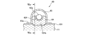
また、図6A及び図6Bに示すように、エレメント62aの外周には、グリス64との接触面積を増やしグリス64からの熱が伝達されやすくなるよう、突起板62fを設けてもよい。このようにすることで、熱媒体流路11を流れる熱媒体の熱をより効率よく熱膨張体62bに伝達させることができる。   6A and 6B, a protrusion plate 62f may be provided on the outer periphery of the element 62a so as to increase the contact area with the grease 64 so that heat from the grease 64 is easily transmitted. By doing in this way, the heat of the heat medium which flows through the heat medium flow path 11 can be more efficiently transmitted to the thermal expansion body 62b.

以上、本発明の実施形態について説明したが、上記実施形態は本発明の適用例の一部を示したに過ぎず、本発明の技術的範囲を上記実施形態の具体的構成に限定する趣旨ではない。   The embodiment of the present invention has been described above. However, the above embodiment only shows a part of application examples of the present invention, and the technical scope of the present invention is limited to the specific configuration of the above embodiment. Absent.

上記実施形態では、熱交換部10の外側に位置する外壁部101を介して熱媒体流路11を流れる熱媒体の熱を伝達させているが、他の方法によっても熱媒体の熱を伝達させることができる。例えば、熱媒体流路11の熱媒体とは直接接触しないよう熱交換部10の内部へ貫通する貫通路を独立して形成し、貫通路近傍の熱媒体流路11から熱媒体の熱を伝達させることができる。また、排熱回収器出口流路11b近傍の熱媒体流路11の一部を、温度センサ61又はエレメント62aに巻きつけて、熱媒体の熱を伝達させることとしてもよい。   In the above embodiment, the heat of the heat medium flowing through the heat medium flow path 11 is transmitted via the outer wall portion 101 positioned outside the heat exchange unit 10, but the heat of the heat medium is also transmitted by other methods. be able to. For example, a through passage that penetrates to the inside of the heat exchanging portion 10 is formed independently so as not to directly contact the heat medium in the heat medium passage 11, and heat of the heat medium is transmitted from the heat medium passage 11 in the vicinity of the through passage. Can be made. Further, a part of the heat medium flow path 11 in the vicinity of the exhaust heat recovery device outlet flow path 11b may be wound around the temperature sensor 61 or the element 62a to transmit the heat of the heat medium.

100 排熱回収器
10 熱交換部
11 熱媒体流路
11b 排熱回収器出口流路
20 バイパス部
30 排気導入部
50 バルブ
60 バルブ切替機構
61 温度センサ
62 アクチュエータ
62a エレメント
62b 熱膨張体
62c ピストン
62d ロッド
62e 非線形バネ
64 グリス
65 ケース
70 コントローラ
101 外壁部
101a 凹部
DESCRIPTION OF SYMBOLS 100 Waste heat recovery device 10 Heat exchange part 11 Heat medium flow path 11b Waste heat recovery device exit flow path 20 Bypass part 30 Exhaust introduction part 50 Valve 60 Valve switching mechanism 61 Temperature sensor 62 Actuator 62a Element 62b Thermal expansion body 62c Piston 62d Rod 62e Non-linear spring 64 Grease 65 Case 70 Controller 101 Outer wall portion 101a Recessed portion

Claims (8)

エンジンから排出された排気と熱交換を行う熱交換部と、
排気を前記熱交換部からバイパスさせるバイパス部と、
前記熱交換部とバイパス部とに排気を振り分けるバルブと、
前記バルブを回動するバルブ切替機構と、
を備え、
前記熱交換部は、排気と熱交換を行うための熱媒体が循環する熱媒体流路を備え、
前記バルブ切替機構は、
前記熱媒体から離間して配置され、前記熱媒体の熱によって応答する熱応答部と、
前記熱応答部の応答により前記バルブを回動させる作動部と、
を備えることを特徴とする排熱回収器。
A heat exchanging section for exchanging heat with the exhaust discharged from the engine;
A bypass section for bypassing exhaust gas from the heat exchange section;
A valve that distributes exhaust gas to the heat exchange section and the bypass section;
A valve switching mechanism for rotating the valve;
With
The heat exchange unit includes a heat medium flow path through which a heat medium for exchanging heat with the exhaust gas circulates,
The valve switching mechanism is
A thermal response portion that is disposed apart from the heat medium and responds by heat of the heat medium;
An operating part for rotating the valve in response to the thermal response part;
An exhaust heat recovery device comprising:
請求項1に記載の排熱回収器であって、
前記熱交換部の外周に形成される外壁部を備え、
前記外壁部には、前記バルブ切替機構の前記熱応答部が当接設置される、
ことを特徴とする排熱回収器。
The exhaust heat recovery device according to claim 1,
An outer wall formed on the outer periphery of the heat exchange unit;
The thermal response part of the valve switching mechanism is installed in contact with the outer wall part,
An exhaust heat recovery device characterized by that.
請求項2に記載の排熱回収器であって、
前記熱交換部は、前記外壁部と前記熱媒体流路との間に排気通路を備え、
前記外壁部には、前記排気通路側に窪んで前記熱媒体流路と当接する凹部が形成され、
前記凹部には、前記凹部の端から所定の隙間を空けて前記熱応答部が設置される、
ことを特徴とする排熱回収器。
The exhaust heat recovery device according to claim 2,
The heat exchange part includes an exhaust passage between the outer wall part and the heat medium flow path,
The outer wall is formed with a recess that is recessed toward the exhaust passage and contacts the heat medium flow path.
In the recess, the thermal response unit is installed with a predetermined gap from an end of the recess.
An exhaust heat recovery device characterized by that.
請求項3に記載の排熱回収器であって、
前記熱媒体流路には、前記排熱回収器内を循環した前記熱媒体を外部に流出させる排熱回収器出口流路が前記排気通路を貫通するように形成され、
前記凹部は、前記排熱回収器出口流路の近傍に形成され、
前記凹部と前記排熱回収器出口流路は、前記排気通路内の排気の流れる方向に並ぶよう配置される、
ことを特徴とする排熱回収器。
The exhaust heat recovery device according to claim 3,
In the heat medium flow path, an exhaust heat recovery device outlet flow channel for allowing the heat medium circulated in the exhaust heat recovery device to flow out is formed so as to penetrate the exhaust passage,
The recess is formed in the vicinity of the exhaust heat recovery device outlet channel,
The concave portion and the exhaust heat recovery device outlet flow path are arranged so as to be aligned in a direction in which the exhaust gas flows in the exhaust passage.
An exhaust heat recovery device characterized by that.
請求項1から請求項4のいずれか一つに記載の排熱回収器であって、
前記バルブ切替機構は、アクチュエータを備え
前記アクチュエータは、
前記熱媒体の熱によって膨張収縮を行うことで前記熱応答部として機能する熱膨張体と、
前記熱膨張体の膨張収縮により進退することで前記作動部として機能するロッドと、
内部に前記熱膨張体と前記ロッドを充填され、前記熱膨張体に前記熱媒体の熱を伝達するエレメントと、
を備える、
ことを特徴とする排熱回収器。
The exhaust heat recovery device according to any one of claims 1 to 4,
The valve switching mechanism includes an actuator.
A thermal expansion body that functions as the thermal response unit by performing expansion and contraction by the heat of the heat medium;
A rod that functions as the operating part by advancing and retracting due to expansion and contraction of the thermal expansion body;
An element filled therein with the thermal expansion body and the rod, and transmitting heat of the heat medium to the thermal expansion body;
Comprising
An exhaust heat recovery device characterized by that.
請求項5に記載の排熱回収器であって、
前記バルブ切替機構は、前記エレメントの外側に配置され、前記熱媒体の熱を伝達する熱伝達体を備え、
前記熱伝達体は、前記エレメントを介して前記熱媒体の熱を前記熱膨張体へと伝達する、
ことを特徴とする排熱回収器。
The exhaust heat recovery device according to claim 5,
The valve switching mechanism is disposed outside the element and includes a heat transfer body that transfers heat of the heat medium,
The heat transfer body transfers heat of the heat medium to the thermal expansion body through the element.
An exhaust heat recovery device characterized by that.
請求項6に記載の排熱回収器であって、
前記排熱回収器との間で密閉空間を形成する断熱構造のケースを備え、
前記熱伝達体と前記エレメントは、前記排熱回収器と前記ケースとの間の前記密閉空間内に封入される、
ことを特徴とする排熱回収器。
The exhaust heat recovery device according to claim 6,
A case with a heat insulating structure that forms a sealed space with the exhaust heat recovery device,
The heat transfer body and the element are enclosed in the sealed space between the exhaust heat recovery device and the case.
An exhaust heat recovery device characterized by that.
請求項7に記載の排熱回収器であって、
前記ケースは、前記アクチュエータ及び前記排熱回収器に接合される、
ことを特徴とする排熱回収器。
The exhaust heat recovery device according to claim 7,
The case is joined to the actuator and the exhaust heat recovery unit,
An exhaust heat recovery device characterized by that.
JP2014137997A 2014-07-03 2014-07-03 Exhaust heat recovery device Pending JP2016014382A (en)

Priority Applications (1)

Application Number Priority Date Filing Date Title
JP2014137997A JP2016014382A (en) 2014-07-03 2014-07-03 Exhaust heat recovery device

Applications Claiming Priority (1)

Application Number Priority Date Filing Date Title
JP2014137997A JP2016014382A (en) 2014-07-03 2014-07-03 Exhaust heat recovery device

Publications (1)

Publication Number Publication Date
JP2016014382A true JP2016014382A (en) 2016-01-28

Family

ID=55230745

Family Applications (1)

Application Number Title Priority Date Filing Date
JP2014137997A Pending JP2016014382A (en) 2014-07-03 2014-07-03 Exhaust heat recovery device

Country Status (1)

Country Link
JP (1) JP2016014382A (en)

Cited By (2)

* Cited by examiner, † Cited by third party
Publication number Priority date Publication date Assignee Title
JP2019116883A (en) * 2017-12-27 2019-07-18 株式会社ユタカ技研 Thermo-actuator
JP2020190258A (en) * 2019-05-20 2020-11-26 富士精工株式会社 Thermo-actuator

Citations (4)

* Cited by examiner, † Cited by third party
Publication number Priority date Publication date Assignee Title
JPS5229393U (en) * 1975-08-21 1977-03-01
JP2010144566A (en) * 2008-12-17 2010-07-01 Calsonic Kansei Corp Switching valve structure
JP2013096274A (en) * 2011-10-31 2013-05-20 Daihatsu Motor Co Ltd On-vehicle power generation system
JP2014092071A (en) * 2012-11-02 2014-05-19 Toyota Motor Corp Exhaust system variable device of internal combustion engine

Patent Citations (4)

* Cited by examiner, † Cited by third party
Publication number Priority date Publication date Assignee Title
JPS5229393U (en) * 1975-08-21 1977-03-01
JP2010144566A (en) * 2008-12-17 2010-07-01 Calsonic Kansei Corp Switching valve structure
JP2013096274A (en) * 2011-10-31 2013-05-20 Daihatsu Motor Co Ltd On-vehicle power generation system
JP2014092071A (en) * 2012-11-02 2014-05-19 Toyota Motor Corp Exhaust system variable device of internal combustion engine

Cited By (2)

* Cited by examiner, † Cited by third party
Publication number Priority date Publication date Assignee Title
JP2019116883A (en) * 2017-12-27 2019-07-18 株式会社ユタカ技研 Thermo-actuator
JP2020190258A (en) * 2019-05-20 2020-11-26 富士精工株式会社 Thermo-actuator

Similar Documents

Publication Publication Date Title
US8327634B2 (en) Exhaust heat recovery system
JP2008157211A (en) Exhaust heat recovery device
CA2885336C (en) Exhaust gas heat recovery apparatus
JP6384409B2 (en) Waste heat recovery unit structure
JP2016014382A (en) Exhaust heat recovery device
JP6167998B2 (en) Exhaust heat recovery device
RU2363904C1 (en) Heat exchanger
JP2008101481A (en) Exhaust system structure
JP2011214529A (en) Exhaust heat recovery device
JP2006084090A (en) Heat pump heat accumulator
KR20110121942A (en) Exhaust heat recovery apparatus
JP6429719B2 (en) Thermo actuator
KR101755852B1 (en) Exhaust heat recovery apparatus
JP2010144566A (en) Switching valve structure
JP6002099B2 (en) Heat exchange device
CN111183278B (en) Thermostat assembly with improved bypass control
JP6145904B2 (en) Heat exchange device
JP6171699B2 (en) Exhaust heat recovery unit
JP6668320B2 (en) Thermo actuator
RU2588335C1 (en) Exhaust gas heat recuperation device
JP2012246870A (en) Waste heat recovery device
JP6668319B2 (en) Thermo actuator
CN114514365B (en) Thermostat device
US11280552B2 (en) Heat exchanger system for transmitting the exhaust gas heat of an internal combustion engine
JP2016109132A (en) Fuel cooling apparatus

Legal Events

Date Code Title Description
RD02 Notification of acceptance of power of attorney

Free format text: JAPANESE INTERMEDIATE CODE: A7422

Effective date: 20161221

A621 Written request for application examination

Free format text: JAPANESE INTERMEDIATE CODE: A621

Effective date: 20170330

A131 Notification of reasons for refusal

Free format text: JAPANESE INTERMEDIATE CODE: A131

Effective date: 20180123

A977 Report on retrieval

Free format text: JAPANESE INTERMEDIATE CODE: A971007

Effective date: 20180124

A02 Decision of refusal

Free format text: JAPANESE INTERMEDIATE CODE: A02

Effective date: 20180717