JP2016010392A - Culture bag and culture method - Google Patents
Culture bag and culture method Download PDFInfo
- Publication number
- JP2016010392A JP2016010392A JP2014135009A JP2014135009A JP2016010392A JP 2016010392 A JP2016010392 A JP 2016010392A JP 2014135009 A JP2014135009 A JP 2014135009A JP 2014135009 A JP2014135009 A JP 2014135009A JP 2016010392 A JP2016010392 A JP 2016010392A
- Authority
- JP
- Japan
- Prior art keywords
- surface film
- culture
- main surface
- heat
- main
- Prior art date
- Legal status (The legal status is an assumption and is not a legal conclusion. Google has not performed a legal analysis and makes no representation as to the accuracy of the status listed.)
- Pending
Links
Images


Landscapes
- Apparatus Associated With Microorganisms And Enzymes (AREA)
- Micro-Organisms Or Cultivation Processes Thereof (AREA)
Abstract
Description
本発明は、被培養物を含む培養液を収容して被培養物を培養する培養袋及び当該培養袋を有する培養装置を用いて被培養物を培養する培養方法に関する。 The present invention relates to a culture bag for culturing a culture medium containing a culture solution containing the culture medium and a culture method for culturing the culture medium using a culture apparatus having the culture bag.
抗体医薬やワクチンなどのバイオ医薬品の開発や製造において、シングルユース製品(使い捨て製品)が着実に浸透しつつある。シングルユース製品は洗浄や滅菌のバリデーション作業が必要ないこと、交叉汚染がないこと、簡易的に無菌環境が得られることなどのメリットがあるため、バイオ医薬品の開発コストを大幅に削減できる場合がある。 Single-use products (disposable products) are steadily penetrating in the development and production of biopharmaceuticals such as antibody drugs and vaccines. Single-use products have advantages such as no need for cleaning and sterilization validation, no cross-contamination, and a simple aseptic environment, which can significantly reduce the development costs of biopharmaceuticals. .
近年シングルユース製品として、被培養物を含む培養液を収容して培養を行う3D培養装置が注目されてきている(例えば特許文献1乃至4参照)。3D培養装置では、エアーを培養袋内に供給しながら撹拌器によって培養液を撹拌して被培養物を培養する。
In recent years, attention has been paid to a 3D culture apparatus that accommodates and cultures a culture solution containing a culture as a single-use product (see, for example,
典型的な培養液を収容する培養袋は、前後方向に対向する一対の主面フィルム本体と、一対の主面フィルム本体の間で上下方向に対向する一対の他面フィルム本体と、を有している。培養袋は、一対の主面フィルム本体及び一対の他面フィルム本体の重ねられた周縁をヒートシールすることにより製袋される。この場合、各他面フィルム本体の周縁に、一方の主面フィルム本体とヒートシールされた部分と、他方の主面フィルム本体とヒートシールされた部分と、の境界となる境界部分が規定される。したがって、この境界部分付近には、この境界部分を含む他面フィルム本体及び当該境界部分を挟んで対面する2つの主面フィルム本体の合計で3つのフィルムが集まることになる。 A culture bag containing a typical culture solution has a pair of main surface film bodies opposed to each other in the front-rear direction, and a pair of other film film bodies opposed in the vertical direction between the pair of main surface film bodies. ing. The culture bag is formed by heat-sealing the overlapped peripheral edges of the pair of main surface film bodies and the pair of other surface film bodies. In this case, a boundary portion serving as a boundary between one main surface film main body and the heat-sealed portion and the other main surface film main body and the heat-sealed portion is defined on the periphery of each other-surface film main body. . Therefore, in the vicinity of this boundary portion, three films are gathered in total, that is, the other film main body including this boundary portion and the two main surface film main bodies facing each other with the boundary portion interposed therebetween.
培養中に、培養袋内に供給されるエアーあるいは培養液圧送等、培養袋に加えられるなんらかの負荷によって培養袋に大きな応力が発生すると、前記境界部分周りに応力が集中してしまう場合がある。境界部分周りに応力が集中すると、当該境界部分を含む他面フィルム本体及び当該境界部分を挟んで対面する2つの主面フィルム本体が平面状に引き延ばされる。この結果、当該3つのフィルムの間に隙間が形成され、この隙間から培養袋内の培養液が漏れてしまうおそれがあった。 During culture, if a large stress is generated in the culture bag due to some load applied to the culture bag, such as air supplied to the culture bag or pressure feeding of the culture solution, the stress may be concentrated around the boundary portion. When stress concentrates around the boundary portion, the other-side film main body including the boundary portion and the two main surface film main bodies facing each other across the boundary portion are stretched in a planar shape. As a result, a gap was formed between the three films, and the culture solution in the culture bag might leak from the gap.
本発明はこのような点を考慮してなされたものであり、培養液が漏れるおそれを低減した培養袋及び当該培養袋を有する培養装置を用いて被培養物を培養する培養方法を提供することを目的とする。 The present invention has been made in view of the above points, and provides a culture bag that reduces the possibility of leakage of a culture solution and a culture method for culturing a culture using a culture apparatus having the culture bag. With the goal.
本発明による第1の培養袋は、被培養物を含む培養液を収容して被培養物を培養する培養袋であって、一方向に対向する一対の主面フィルム本体を含む主面フィルムと、前記一対の主面フィルム本体の間で、前記一方向に交差する他方向に対向して配置された一対の他面フィルム本体と、を備え、主面フィルム本体の周縁と他面フィルム本体の周縁とがヒートシールされて第1シール領域が形成され、主面フィルム同士がヒートシールされて第2シール領域が形成され、一方の他面フィルム本体の周縁のうちの、一方の主面フィルム本体とヒートシールされた第1部分と他方の主面フィルム本体とヒートシールされた第2部分との境界となる境界部分に沿って、前記一方の他面フィルム本体を折り畳んだときに、前記第1部分と前記第2部分との重なり合う位置に、前記第1部分と前記第2部分とを固定する固定領域が設けられている。 A first culture bag according to the present invention is a culture bag that contains a culture solution containing a culture to be cultured and cultures the culture, and includes a main surface film including a pair of main surface film bodies facing in one direction; A pair of other film main bodies disposed opposite to each other in a direction intersecting the one direction between the pair of main film main bodies, and a peripheral edge of the main film main body and the other film main body. The peripheral edge is heat-sealed to form a first seal area, the main-surface films are heat-sealed to form a second seal area, and one main-surface film body of the peripheral edges of the other-side film body When the one other-side film body is folded along a boundary portion that becomes a boundary between the heat-sealed first portion and the other main-surface film body and the heat-sealed second portion, the first-side film body is folded. Part and said second part The overlapping position, the fixed area for fixing the said first portion and said second portion is provided.
本発明による第1の培養袋において、前記第1部分と前記第2部分とを接合する接合材料によって、前記固定領域が形成されていてもよい。 In the first culture bag according to the present invention, the fixing region may be formed by a bonding material for bonding the first portion and the second portion.
本発明による第1の培養袋において、前記第1部分に孔が形成され、前記境界部分に沿って前記一方の他面フィルム本体を折り畳んだときに前記第1部分に形成された孔と重なり合う前記第2部分の位置に、孔が形成され、前記接合材料は、前記第1部分に形成された孔と、前記第2部分に形成された孔とに、充填されていてもよい。 In the first culture bag according to the present invention, a hole is formed in the first part, and the hole overlaps with the hole formed in the first part when the one other-side film body is folded along the boundary part. A hole is formed at the position of the second portion, and the bonding material may be filled in the hole formed in the first portion and the hole formed in the second portion.
本発明による第1の培養袋において、前記第1部分とヒートシールされた前記一方の主面フィルム本体の部分と、前記第2部分とヒートシールされた前記他方の主面フィルム本体の部分と、に亘って貼り付けられた接合テープによって前記第1部分と前記第2部分とが互いに固定され、前記固定領域が規定されていてもよい。 In the first culture bag according to the present invention, the portion of the one main surface film body heat-sealed with the first portion, the portion of the other main surface film body heat-sealed with the second portion, The first portion and the second portion may be fixed to each other by a bonding tape that is pasted to define the fixing region.
本発明による第1の培養袋において、前記第1部分とヒートシールされた前記一方の主面フィルム本体の部分と、前記第2部分とヒートシールされた前記他方の主面フィルム本体の部分と、を挟持するクリップ部材によって前記第1部分と前記第2部分とが互いに固定され、前記固定領域が規定されていてもよい。 In the first culture bag according to the present invention, the portion of the one main surface film body heat-sealed with the first portion, the portion of the other main surface film body heat-sealed with the second portion, The first portion and the second portion may be fixed to each other by a clip member that sandwiches the clip, thereby defining the fixing region.
本発明による第1の培養袋において、前記固定領域は、前記境界部分から前記他方向にずれた位置に配置されていてもよい。 In the first culture bag according to the present invention, the fixed region may be arranged at a position shifted in the other direction from the boundary portion.
本発明による第2の培養袋は、被培養物を含む培養液を収容して被培養物を培養する培養袋であって、一方向に対向する一対の主面フィルム本体を含む主面フィルムと、前記一対の主面フィルム本体の間で、前記一方向に交差する他方向に対向して配置された一対の他面フィルム本体と、を備え、主面フィルム本体の周縁と他面フィルム本体の周縁とがヒートシールされて第1シール領域が形成され、主面フィルム同士がヒートシールされて第2シール領域が形成され、一方の主面フィルム本体の第1シール領域及び第2シール領域をなす部分以外の部分と、一方の他面フィルム本体の第1シール領域をなす部分以外の部分と、が重なる位置に、前記一方の主面フィルム本体と前記一方の他面フィルム本体とを固定する固定領域が設けられていて、前記固定領域は、前記一方の他面フィルム本体の周縁のうちの、前記一方の主面フィルム本体とヒートシールされた第1部分と他方の主面フィルム本体とヒートシールされた第2部分との境界となる境界部分よりも袋内方に位置している。 A second culture bag according to the present invention is a culture bag that contains a culture solution containing a culture medium and cultures the culture medium, and includes a main surface film including a pair of main surface film bodies facing in one direction; A pair of other film main bodies disposed opposite to each other in a direction intersecting the one direction between the pair of main film main bodies, and a peripheral edge of the main film main body and the other film main body. The peripheral edge is heat-sealed to form a first seal region, the main surface films are heat-sealed to form a second seal region, and form the first seal region and the second seal region of one main surface film body. Fixing that fixes the one main surface film main body and the one other surface film main body at a position where a portion other than the portion overlaps with a portion other than the portion forming the first seal region of the one other surface film main body. An area is provided The fixing region includes a first portion heat-sealed with the one main surface film main body and a second portion heat-sealed with the other main surface film main body in the peripheral edge of the one other surface film main body. It is located inside the bag from the boundary part that becomes the boundary.
本発明による第2の培養袋において、前記一方の主面フィルム本体と前記一方の他面フィルム本体とがヒートシールされることにより、前記固定領域が形成されていてもよい。 In the second culture bag according to the present invention, the fixed region may be formed by heat sealing the one main surface film main body and the one other surface film main body.
本発明による第2の培養袋において、前記一方の主面フィルム本体と前記一方の他面フィルム本体との間に追加フィルム片が配置されていて、前記一方の主面フィルム本体と前記一方の他面フィルム本体と共に前記追加フィルム片がヒートシールされることにより、前記固定領域が形成されていてもよい。 In the second culture bag according to the present invention, an additional film piece is disposed between the one main surface film main body and the one other surface film main body, and the one main surface film main body and the other one of the one main surface film main body are arranged. The said fixed area | region may be formed by heat-sealing the said additional film piece with a surface film main body.
本発明による第3の培養袋は、被培養物を含む培養液を収容して被培養物を培養する培養袋であって、一方向に対向する一対の主面フィルム本体を含む主面フィルムと、前記一対の主面フィルム本体の間で、前記一方向に交差する他方向に対向して配置された一対の他面フィルム本体と、を備え、主面フィルム本体の周縁と他面フィルム本体の周縁とがヒートシールされて第1シール領域が形成され、主面フィルム同士がヒートシールされて第2シール領域が形成され、一対の主面フィルム本体の第1シール領域及び第2シール領域をなす部分以外の部分が互いに重なる位置に、当該一対の主面フィルム本体を互いに固定する固定領域が設けられていて、前記固定領域は、一方の主面フィルム本体の周縁のうちの、他方の主面フィルム本体とヒートシールされた第3部分と一方の他面フィルム本体とヒートシールされた第4部分との境界となる境界部分よりも袋内方に位置している。 A third culture bag according to the present invention is a culture bag for containing a culture solution containing a culture to be cultured and culturing the culture, and a main surface film including a pair of main surface film bodies facing in one direction; A pair of other film main bodies disposed opposite to each other in a direction intersecting the one direction between the pair of main film main bodies, and a peripheral edge of the main film main body and the other film main body. The peripheral edge is heat sealed to form a first seal region, the main surface films are heat sealed to form a second seal region, and form a first seal region and a second seal region of a pair of main surface film bodies. A fixing region for fixing the pair of main surface film main bodies to each other is provided at a position where portions other than the portions overlap each other, and the fixing region is the other main surface of the peripheral edges of the one main surface film main body. With the film body Than Toshiru been third portion and one of the other surface the film body and heat sealed boundary to become a boundary portion between the fourth portion is positioned bag side.
本発明による第3の培養袋において、前記一対の主面フィルム本体の互いに重なる部分がヒートシールされることにより、前記固定領域が形成されていてもよい。 In the third culture bag according to the present invention, the fixed region may be formed by heat-sealing portions of the pair of main surface film bodies that overlap each other.
本発明による第3の培養袋において、一対の主面フィルム本体の互いに重なる部分の間に追加フィルム片が配置されていて、一対の主面フィルム本体の互いに重なる部分と共に前記追加フィルム片がヒートシールされることにより、前記固定領域が形成されていてもよい。 In the third culture bag according to the present invention, an additional film piece is disposed between the overlapping portions of the pair of main surface film bodies, and the additional film piece is heat sealed together with the overlapping portions of the pair of main surface film bodies. By doing so, the fixed region may be formed.
本発明による培養方法は、前記いずれかの特徴をもつ培養袋を有する培養装置を用いて被培養物を培養する培養方法であって、前記培養袋内に加圧状態で培養液を注入する工程と、前記培養袋内にエアーを供給し前記培養袋内を加圧状態にして被培養物を培養する工程と、を備える。 The culturing method according to the present invention is a culturing method for culturing an object to be cultured using a culturing apparatus having a culture bag having any one of the above characteristics, and a step of injecting a culture solution in a pressurized state into the culture bag And a step of supplying air into the culture bag and culturing the culture object under pressure in the culture bag.
本発明によれば、固定領域が境界部分の周りに応力が集中することを緩和するように機能する。これにより、境界部分を含む他面フィルム本体及び境界部分を挟んで対面する2つの主面フィルム本体が平面状に引き延ばされて形成され得る隙間から培養液が漏れるおそれを低減することができる。 According to the present invention, the fixed region functions to relieve stress concentration around the boundary portion. Thereby, the possibility that the culture solution leaks from the gap that can be formed by extending the other main surface film body including the boundary portion and the two main surface film main bodies facing each other across the boundary portion in a flat shape can be reduced. .
≪第1の実施の形態≫
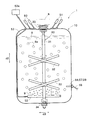
以下、図面を参照して本発明の一実施の形態について説明する。なお、本明細書に添付する図面においては、図示と理解のしやすさの便宜上、適宜縮尺及び縦横の寸法比等を、実物のそれらから変更し誇張してある。図1乃至図10は、本発明による第1の実施の形態を説明するための図である。このうち図1は、本発明の第1の実施の形態による培養装置1を示す正面図であり、図2は、図1に示す培養装置1の培養袋10を示す斜視図である。
<< First Embodiment >>
Hereinafter, an embodiment of the present invention will be described with reference to the drawings. In the drawings attached to the present specification, for the sake of illustration and ease of understanding, the scale and the vertical / horizontal dimensional ratio are appropriately changed and exaggerated from those of the actual ones. 1 to 10 are diagrams for explaining a first embodiment according to the present invention. 1 is a front view showing the
図1に示す培養装置1は、細胞、微生物、菌等の被培養物8aを含む培養液8を収容して被培養物8aを培養するためのものである。図1に示すように、培養装置1は、培養液8を収容する培養袋10と、培養袋10内で回転可能に設けられた攪拌器30と、を備えている。このうち、培養袋10は、図2に示すように、一方向d1に対向して配置された一対の主面フィルム本体12、13を含む主面フィルム11と、一対の主面フィルム本体12、13の間で、一方向d1に交差する他方向d2に対向して配置された一対の他面フィルム本体14、15と、を有している。培養装置1の設置状態において、一対の主面フィルム本体12、13は前後方向に対向し、一対の他面フィルム本体14、15は上下方向に対向する。したがって、培養装置1の設置状態において、一方向d1は前後方向に一致し、他方向d2は前後方向に直交する上下方向に一致する。以下では、培養装置1の設置状態を基準として、培養装置1を構成する各構成要素について説明していく。したがって、一方向を前後方向d1とし、他方向を上下方向d2とする。
A
攪拌器30は、培養袋10内で回転可能に設けられ、上下方向d2に延びる回転シャフト31と、回転シャフト31に設けられた複数の撹拌翼32と、を有している。回転シャフト31の上端部及び下端部は、培養袋10に回転可能に支持されている。すなわち、培養袋10の上面をなす上他面フィルム本体14には、回転シャフト31の上端部を回転可能に支持する上側軸受部33が設けられ、培養袋10の下面をなす下他面フィルム本体15には、回転シャフト31の下端部を回転可能に支持する下側軸受部34が設けられている。攪拌器30の回転シャフト31の上端部には、撹拌駆動装置6から磁気カップリング方式で駆動力が伝達されるようになっている。
The
複数の撹拌翼32は、上下方向d2に沿って並べて配置されている。本実施の形態では、2つの撹拌翼32が上下方向d2に沿って間隔をあけて配置されている。撹拌器30が複数の撹拌翼32を有することにより、培養袋10内の培養液8をよりムラなく攪拌することができるようになっている。
The plurality of stirring
撹拌器30によれば、撹拌駆動装置6から伝達される駆動力によって、攪拌器30の回転シャフト31および撹拌翼32が回転するようになっている。
According to the
次に、培養液8を収容する培養袋10について図3乃至図7も参照して説明する。図3は、培養袋10を示す分解斜視図である。上述のように、培養袋10は、前後方向d1に対向して配置された表主面フィルム本体12及び裏主面フィルム本体13を含む主面フィルム11と、表主面フィルム本体12と裏主面フィルム本体13との間で、上下方向d2に対向して配置された上他面フィルム本体14及び下他面フィルム本体15と、を有している。培養袋10は、各フィルム12〜15の縁部をヒートシールすることにより製袋されている。そして、各フィルム12〜15に囲まれる空間内に培養液8を収容する収容空間Sが形成されている。なお、図示する例では、主面フィルム11は、2つのフィルム材料からなり、各フィルム材料が1つの主面フィルム本体を構成する例を示しているが、このような例に限定されない。主面フィルム11は、単一のフィルム材料からなり、単一のフィルム材料が一方向d1に対向する一対の主面フィルム本体を含んでもよい。
Next, the
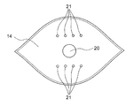
図4乃至図7は、それぞれ、培養袋10の表主面フィルム本体12、裏主面フィルム本体13、上他面フィルム本体14及び下他面フィルム本体15を示す図である。図4及び図5に示すように、各主面フィルム本体12、13の周縁は、円弧状の上縁及び下縁と、上縁及び下縁の端部の間を延びる2つの側縁と、を有している。より詳細には、上縁は、上下方向d2における上方に凸となる半円弧状の形状をもち、下縁は、上下方向d2における下方に凸となる半円弧状の形状をもつ。各側縁は、上縁及び下縁の端部の間を上下方向d2に沿って延びる直線状の形状をもつ。一方、図6及び図7に示すように、上他面フィルム本体14及び下他面フィルム本体15の周縁は、略楕円形の形状を有している。図2に示すように、培養袋10が製袋された状態において、上他面フィルム本体14は、下方に凸となるように撓み、前後方向d1及び上下方向d2に直交する横方向d3に延びる折目線14fに沿って折り畳み可能になっている。同様に、下他面フィルム本体15は、上方に凸となるように撓み、前後方向d1及び上下方向d2に直交する横方向d3に延びる折目線15fに沿って折り畳み可能になっている。
4 to 7 are diagrams showing the front main surface film
上述のように、各フィルム12、13、14、15の縁部は、ヒートシールにより接合されている。ヒートシールとしては、例えばインパルスシールやバーシール、超音波溶着、振動溶着、高周波溶着、半導体レーザー溶着、スピン溶着が挙げられる。本実施の形態では、互いに重ねられた主面フィルム本体12、13の周縁と他面フィルム本体14、15の周縁とがヒートシールされて第1シール領域16が形成されている。とりわけ、表主面フィルム本体12の上縁と上他面フィルム本体14の周縁とがヒートシールにより接合された領域を、上表第1シール領域16aと呼び、裏主面フィルム本体13の上縁と上他面フィルム本体14の周縁とがヒートシールにより接合された領域を、上裏第1シール領域16bと呼ぶ。
As described above, the edges of the
上述のように、各主面フィルム本体12、13の上縁部は、上方に凸となるように湾曲状に形成されている。このことにより、上縁部に沿って形成される上表第1シール領域16a及び上裏第1シール領域16bは、上方に凸となるように湾曲状に形成されている。同様に、各主面フィルム本体12、13の下縁部は、下方に凸となるように湾曲状に形成されており、下縁部に沿って形成される各第1シール領域16は、下方に凸となるように湾曲状に形成されている。
As described above, the upper edge portions of the main
また、互いに重ねられた一対の主面フィルム本体12、13の周縁がヒートシールされて第2シール領域17が形成されている。すなわち、表主面フィルム本体12の両側縁部と裏主面フィルム本体13の両側縁部とがヒートシールにより接合されて、第2シール領域17がそれぞれ形成されている。図2に示す例では、各第2シール領域17は、上下方向d2に沿って略直線状に延びている。
Moreover, the 2nd seal | sticker area |
図4に示すように、表主面フィルム本体12には、複数の物性用開孔23が互いに間隔を空けて配置されている。図4に示す例では、3つの物性用開孔23が設けられており、図1に示す温度センサ56、pHセンサ57およびDo(溶存酸素)センサ58が、対応する物性用開孔23に挿入されている。温度センサ56は、培養袋10内の培養液8の温度を計測し、pHセンサ57は、培養袋10内の培養液8のpHを計測し、Doセンサ58は、培養袋10内の培養液8の溶存酸素量を計測するためのものである。
As shown in FIG. 4, a plurality of
加えて、これら3つの物性用開孔23に並べてサンプリング用開孔24が配置されている。サンプリング用開孔24には、図1に示すサンプリングチューブ59が挿入されている。表主面フィルム本体12にサンプリングチューブ59が取り付けられていることにより、培養中の培養液8をサンプリングチューブ59から取り出し可能となる。
In addition, a
図6に示すように、上他面フィルム本体14には、前述の上側軸受部33を装置するための上側軸受開孔20が形成されている。また、培養袋10の上他面フィルム本体14には、図1に示す培養液注入チューブ50、気体排出部51及び気体供給チューブ53を取り付けるための上面開孔21が設けられている。培養液注入チューブ50は、不図示の培養液供給部から供給される被培養物8aを含む培養液8を、培養袋10内に注入するべく設けられている。
As shown in FIG. 6, the upper other
気体供給チューブ53は、気体供給部53aから培養袋10内の培養液8に空気9を供給するためのものである。気体供給チューブ53は、上面開孔21を通って裏主面フィルム本体13に沿って延び、培養袋10内に配置された気体導入部52に接続されている。ここで、図5に示すように、気体供給チューブ53を培養袋10内に固定するべく、裏主面フィルム本体13の内面に3つの保持バンド54が取付けられている。
The
気体供給チューブ53に接続された気体導入部52は、スパージャーとも呼ばれる。気体導入部52は、気体供給チューブ53から供給される空気9等の気体を、培養袋10内の培養液8に分散させて供給するためのものである。気体導入部52は、下他面フィルム本体15に沿って配置されている。
The
図7に示すように、下他面フィルム本体15の内面には、気体導入部52を培養袋10内に固定するための3つの保持バンド55が取付けられている。加えて、下他面フィルム本体15には、前述の下側軸受部34を装置するための下側軸受開孔22が形成されている。
As shown in FIG. 7, three holding
なお、培養袋10に取り付けられる上述した培養液注入部50、サンプリングチューブ59のような各チューブ類及び温度センサ56のような各種センサ類の配置は、図1に示すような配置に限られることはなく、仕様に応じて任意に設定可能である。例えば、培養袋10の仕様の一例として、200Lまで培養液を収容可能な200L用の培養袋と、50Lまで培養液を収容可能な50L用培養袋が知られている。典型的には、図示する200L用の培養袋では、裏主面フィルム本体13に気体導入部52を保持する3つの保持バンド54が設けられ、不図示の50L用の培養袋では、裏主面フィルム本体13に2つの保持バンド54が設けられ得る。
It should be noted that the arrangement of each of the tubes such as the culture
次に、培養袋10を構成する各フィルム12〜15の層構成について説明する。図8は、培養袋10を構成する各フィルム12〜15の層構成の一例を示す断面図である。図8に示すように、各フィルム12〜15をなす積層体60は、ポリエチレン層61、エチレンビニルアルコール層62、ナイロン層63及びポリエチレンテレフタレート層64をこの順で含んでいる。一例として、積層体60の厚みは、100μm〜350μm程度に設定される。
Next, the layer structure of each film 12-15 which comprises the
このうち、ポリエチレン層61は、主としてポリエチレン成分からなる層である。ポリエチレン層61は、ヒートシール性をもち、他のフィルム12〜15にヒートシールされる。ポリエチレン層61は、積層体60の一方の表面をなしている。したがって、積層体60からなる各フィルム12〜15は、ポリエチレン層61が配置された面が他のフィルム12〜15側に向くようにして配置される。
Among these, the
エチレンビニルアルコール層62は、主としてエチレンビニルアルコール共重合体成分からなる層である。エチレンビニルアルコール層62は、積層体60にガスバリア性を付与すべく設けられている。ナイロン層63は、主としてナイロン成分からなる層である。ナイロン層63は、積層体60に耐ピンホール性とりわけ耐突き刺し性、耐屈曲性及び耐摩耗性を付与するべく設けられている。ポリエチレンテレフタレート層64は、主としてポリエチレンテレフタレート成分からなる層である。ポリエチレンテレフタレート層64は、ポリエチレン層61、エチレンビニルアルコール層62及びナイロン層63を支持する基材として機能する。また、ポリエチレンテレフタレート層64は、積層体60に耐熱性を付与する機能をもつ。
The ethylene vinyl alcohol layer 62 is a layer mainly composed of an ethylene vinyl alcohol copolymer component. The ethylene vinyl alcohol layer 62 is provided to give gas barrier properties to the
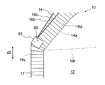
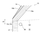
さて、上述のように、各他面フィルム本体14、15は横方向d3に平行な折目線14f、15fに沿って折り畳み可能に構成されおり、折目線14f、15fに対して表側となる他面フィルム本体14、15の周縁は、表主面フィルム本体12にヒートシールされ、折目線14fに対して裏側となる他面フィルム本体14、15の周縁は、裏主面フィルム本体13にヒートシールされる。したがって、各他面フィルム本体14、15の周縁には、表主面フィルム本体12とヒートシールされた第1部分14aと、裏主面フィルム本体13とヒートシールされた第2部分14bと、第1部分14aと第2部分14bと境界となり且つ折目線14fが通過する境界部分14cと、が規定される。図9に、境界部分14c付近を拡大して示す。
As described above, the other-
図9に示すように、この境界部分14cの周りには、この境界部分14cを含む上他面フィルム本体14及び当該境界部分14cを挟んで対面する2つの主面フィルム本体12、13の合計で3つのフィルム12、13、14が集まることになる。前述のように、培養中に、培養袋10に大きな応力が負荷されると、境界部分14c周りに応力が集中し、当該境界部分14cを含む他面フィルム本体14及び当該境界部分14cを挟んで対面する2つの主面フィルム本体12、13が平面状に引き延ばされ得る。これら3つのフィルム12、13、14が平面状に引き延ばされた結果、当該3つのフィルム12、13、14の間に隙間が形成され、この隙間から培養袋10内の培養液8が漏れてしまうおそれがあった。そこで、図2に示すように、培養装置1は、境界部分14c周りに応力が集中することを緩和すべく、境界部分14cに沿って他面フィルム本体14を折り畳んだときに第1部分14aと第2部分14bとの重なり合う位置に、第1部分14aと第2部分14bとを固定する固定領域90が形成されている。このような形態によれば、固定領域90が境界部分14cの周りに集まる応力を緩和するように機能する。
As shown in FIG. 9, around the
なお、図2から理解されるように、このような境界部分は、上他面フィルム本体14の周縁に2箇所形成され、下他面フィルム本体15の周縁に2箇所形成され、合計で4つある。したがって、本実施の形態では、各境界部分にそれぞれ対応する固定領域90が配置され、合計で4つの固定領域が設けられている。以下の説明では、図2に一点鎖線で囲まれた領域Aに配置された固定領域90について説明するが、その他の3つの固定領域90についても略同様に構成することが可能である。
As can be understood from FIG. 2, two such boundary portions are formed on the peripheral edge of the upper other surface film
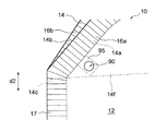
上述のように、固定領域90とは、第1部分14aと第2部分14bとを固定する領域をいう。図10に、図2に一点鎖線で囲まれた領域Aに配置された固定領域90を拡大して示す。図10に示すように、固定領域90は、境界部分14cから上下方向d2における上方にずれた位置に配置されている。言い換えると、固定領域90は、境界部分14cと上下方向d2に対面した位置に配置されている。また、固定領域90の輪郭は、第1部分14aの輪郭に囲まれる部分よりも内方に位置し、且つ、第2部分14bの輪郭に囲まれる部分よりも内方に位置する。
As described above, the fixing
本実施の形態の固定領域90は、表主面フィルム本体12の正面方向からみて略円形の輪郭を有している。ただし、固定領域90の輪郭は、略円形の例に限定されず、種々の形状からなる例が想定され得る。
The fixing
図10に示す例では、上他面フィルム14の周縁のうちの、表主面フィルム本体12とヒートシールされた第1部分14aに、孔14a1が形成され、上他面フィルム14の周縁のうちの、裏主面フィルム本体13とヒートシールされた第2部分14bに、孔14b1が形成されている。この第1部分14aに設けられた孔14a1と第2部分14bに設けられた孔14b1とは、境界部分14cに沿って上他面フィルム本体14を折り畳んだときに、重なり合うようになっている。そして、上他面フィルム本体14を折目線14fに沿って折り畳んで第1部分14aの孔14a1と第2部分14bの孔14b1とが重なり合った状態で、第1部分14aの孔14a1と第2部分14bの孔14b1とに、接合材料92が充填されている。したがって、接合材料92によって第1部分14aと第2部分14bとが固定されて、固定領域90が形成されることになる。
In the example shown in FIG. 10, the
次に、以上のような構成からなる本実施の形態の培養装置1の使用方法について説明する。
Next, the usage method of the
まず、培養袋10内に加圧状態で培養液8を注入する工程を行う。具体的には、図1に示すように、上他面フィルム本体14に接続された培養液注入チューブ50から、培養袋10内に被培養物8aを含む培養液8が加圧状態で注入される。この際、上他面フィルム本体14に接続された気体排出部51から、培養袋10内の気体が排出される。加圧状態で培養液8を注入することにより、素早く培養液8を培養袋10内に注入することができる。
First, a step of injecting the
次に、培養袋10内に気体を供給し培養袋10内を加圧状態にして被培養物8aを培養する工程を行う。具体的には、撹拌駆動装置6から伝達される駆動力によって、攪拌器30の回転シャフト31および撹拌翼32を回転させる。これにより、培養袋10内の培養液8が撹拌されていく。培養を行っている間、培養装置1の気体供給部53aから気体供給チューブ53を通って気体導入部52に空気9が供給される。そして、気体導入部52から、対流している培養液8に空気9が供給され、培養袋10内が加圧状態にされる。培養袋10内が加圧状態となるように培養袋10内に空気9を供給することにより、培養液8に充分な酸素を行き渡せることが可能となる。
Next, a process of supplying gas into the
培養が終了すると、攪拌器30を停止させ、培養袋10内での培養液8の撹拌が止まる。その後、培養袋10から下側軸受部34を介して培養液8が排出される。なお、培養中に必要に応じて、サンプリングチューブ59から培養中の培養液8が取り出されて、培養状態の確認が行われてもよい。
When the culture is completed, the
以上のように、本実施の形態によれば、一方向d1に対向して配置された一対の主面フィルム本体12、13と、一対の主面フィルム本体12、13の間で、一方向d1に交差する他方向d2に対向して配置された一対の他面フィルム本体14、15と、を備え、主面フィルム本体12、13の周縁と他面フィルム本体14、15の周縁とがヒートシールされて第1シール領域16が形成され、主面フィルム11同士がヒートシールされて第2シール領域17が形成され、一方の他面フィルム本体14の周縁のうちの、一方の主面フィルム本体12とヒートシールされた第1部分14aと他方の主面フィルム本体13とヒートシールされた第2部分14bとの境界となる境界部分14cに沿って、一方の他面フィルム本体14を折り畳んだときに、第1部分14aと第2部分14bとの重なり合う位置に、第1部分14aと第2部分14bとを固定する固定領域90が設けられている。このような形態によれば、固定領域90が境界部分14cの周りに集まる応力を緩和するように機能する。これにより、境界部分14cを含む他面フィルム本体14及び境界部分14cを挟んで対面する2つの主面フィルム本体12、13が平面状に引き延ばされることを抑制することができる。この結果、3つのフィルム12、13、14が平面状に引き延ばされて形成され得る隙間から培養液8が漏れるおそれを低減することができる。この結果、培養袋10内に供給される気体あるいは培養袋10に加えられるなんらかの負荷によって培養袋10に大きな応力が発生しても、培養袋10が培養液8の漏れに対して充分な耐性を発揮することができる。
As described above, according to the present embodiment, the unidirectional d1 between the pair of main surface film
さらに、第1部分14aと第2部分14bとが重なる位置に固定領域90が設けられていることから、固定領域90を設けることに起因して培養液8を収容する収容空間Sを狭める、というおそれもない。
Furthermore, since the fixed
また、本実施の形態によれば、第1部分14aと第2部分14bとを接合する接合材料92によって固定領域90が形成されている。このような形態によれば、ヒートシールされた第1部分14aと、ヒートシールされた第2部分14bとを、互いに堅固に固定することができる。
Further, according to the present embodiment, the fixed
とりわけ、本実施の形態によれば、第1部分14aに孔14a1が設けられ、境界部分14cに沿って一方の他面フィルム本体14を折り畳んだときに第1部分14aに設けられた孔14a1と重なり合う第2部分14bの位置に、孔14b1が設けられ、接合材料92は、第1部分14aに設けられた孔14a1と、第2部分14bに設けられた孔14b1とに、充填されている。一般に、第1部分14a及び第2部分14bに孔14a1、14b1を精度よく形成することは容易である。このことから、接合材料92を、第1部分14aの孔14a1と第2部分14bの孔14b1とに充填することにより、接合材料92を精度よく位置決めすることができる。結果として、第1部分14aと第2部分14bとを固定する固定領域90を精度よく形成することに寄与する。
In particular, according to the present embodiment, the hole 14a1 is provided in the
また、本実施の形態によれば、固定領域90は、境界部分14cから他方向d2にずれた位置に配置されている。この場合、境界部分14cに相対的に近い位置に固定領域90を配置することができるため、収容空間Sを狭めることなく、境界部分14cの周りに集まる応力を効果的に緩和することができる。
Further, according to the present embodiment, the fixed
≪変形例≫
なお、上述した実施の形態に対して様々な変更を加えることが可能である。以下、図面を参照しながら、変形の一例について説明する。以下の説明および以下の説明で用いる図面では、上述した実施の形態と同様に構成され得る部分について、上述の実施の形態における対応する部分に対して用いた符号と同一の符号を用いることとし、重複する説明を省略する。
≪Modification≫
Note that various modifications can be made to the above-described embodiment. Hereinafter, an example of modification will be described with reference to the drawings. In the following description and the drawings used in the following description, the same reference numerals as those used for the corresponding parts in the above embodiment are used for the parts that can be configured in the same manner as in the above embodiment. A duplicate description is omitted.
上述した実施の形態では、図10に示すように、第1部分14aと第2部分14bとを接合する接合材料92によって、固定領域90が形成された例を示したが、固定領域90の形態はこのような例に限定されない。図11及び図12に、固定領域90の変形例を示す。このうち、図11に示す例では、上表第1シール領域16aと上裏第1シール領域16bとに亘って、接合テープ93が貼り付けられている。言い換えると、第1部分14aとヒートシールされた一方の主面フィルム本体12の部分と、第2部分14bとヒートシールされた他方の主面フィルム本体13の部分と、に亘って接合テープ93が貼り付けられている。この接合テープ93によって、第1部分14aと第2部分14bとが互いに固定される。したがって、接合テープ93によって、第1部分14aと第2部分14bとを固定する固定領域90が実現される。図11に示す例では、固定領域90は、境界部分14cから上下方向d2にずれた位置に配置されている。このような形態によれば、固定領域90が境界部分14cの周りに集まる応力を緩和するように機能する。これにより、境界部分14cを含む他面フィルム本体14及び境界部分14cを挟んで対面する2つの主面フィルム本体12、13が平面状に引き延ばされることを抑制することができる。この結果、3つのフィルム12、13、14が平面状に引き延ばされて形成され得る隙間から培養液8が漏れるおそれを低減することができる。
In the above-described embodiment, as shown in FIG. 10, the example in which the fixed
一方、図12に示す例では、上表第1シール領域16aと上裏第1シール領域16bとを、クリップ部材94が挟持している。言い換えると、第1部分14aとヒートシールされた一方の主面フィルム本体12の部分と、第2部分14bとヒートシールされた他方の主面フィルム本体13の部分と、をクリップ部材94が挟持している。このクリップ部材94によって、第1部分14aと第2部分14bとが互いに固定される。したがって、クリップ部材94によって、第1部分14aと第2部分14bとを固定する固定領域90が実現される。図12に示す例では、固定領域90は、境界部分14cから上下方向d2にずれた位置に配置されている。このような形態によれば、固定領域90が境界部分14cの周りに集まる応力を緩和するように機能する。これにより、境界部分14cを含む他面フィルム本体14及び境界部分14cを挟んで対面する2つの主面フィルム本体12、13が平面状に引き延ばされることを抑制することができる。この結果、3つのフィルム12、13、14が平面状に引き延ばされて形成され得る隙間から培養液8が漏れるおそれを低減することができる。
On the other hand, in the example shown in FIG. 12, the
≪第2の実施の形態≫
次に、図13を参照して、本発明の第2の実施の形態について説明する。図13は、本発明の第2の実施の形態における培養装置1の要部を示す部分斜視図である。図13を参照して説明する第2の実施の形態は、固定領域90の形態が異なるが、その他の構成は第1の実施形態と同様に構成することができる。第2の実施の形態に関する以下の説明および以下の説明で用いる図面では、上述した第1の実施の形態と同様に構成され得る部分について、上述の第1の実施の形態における対応する部分に対して用いた符号と同一の符号を用いることとし、重複する説明を省略する。
<< Second Embodiment >>
Next, a second embodiment of the present invention will be described with reference to FIG. FIG. 13 is a partial perspective view showing a main part of the
図13に示すように、表主面フィルム本体12の第1シール領域16及び第2シール領域17をなす部分以外の部分と、上他面フィルム本体14の第1シール領域16をなす部分以外の部分と、が重なる位置に、表主面フィルム本体12と上他面フィルム本体14とを固定する固定領域90が設けられている。固定領域90は、上他面フィルム本体14の境界部分14cよりも袋内方に位置している。本実施の形態では、固定領域90は、境界部分14cの周りに配置されている。つまり、固定領域90は、境界部分14cの周りに集まる応力を有効に緩和するように機能するような位置に配置されている。
As shown in FIG. 13, a portion other than the portion forming the
上述のように、各フィルム12、14をなす積層体60は、ヒートシール性をもつポリエチレン層61が他のフィルム12、14に面するように配置されている。したがって、表主面フィルム本体12と上他面フィルム本体14の互いに重なる部分をヒートシールすることにより、当該表主面フィルム本体12と上他面フィルム本体14とを互いに固定することができる。つまり、固定領域90は、表主面フィルム本体12と上他面フィルム本体14とがヒートシールされることにより、形成されている。
As described above, the laminate 60 forming each of the
以上のように、本実施の形態によれば、一方の主面フィルム本体12の第1シール領域16及び第2シール領域17をなす部分以外の部分と、一方の他面フィルム本体14の第1シール領域16をなす部分以外の部分と、が重なる位置に、一方の主面フィルム本体12と一方の他面フィルム本体14とを固定する固定領域90が設けられていて、固定領域90は、一方の他面フィルム本体14の周縁のうちの、一方の主面フィルム本体12とヒートシールされた第1部分14aと他方の主面フィルム本体13とヒートシールされた第2部分14bとの境界となる境界部分14cよりも袋内方に位置している。このような形態によれば、固定領域90が境界部分14cの周りに集まる応力を緩和するように機能する。これにより、境界部分14cを含む他面フィルム本体14及び境界部分14cを挟んで対面する2つの主面フィルム本体12、13が平面状に引き延ばされることを抑制することができる。この結果、3つのフィルム12、13、14が平面状に引き延ばされて形成され得る隙間から培養液8が漏れるおそれを低減することができる。
As described above, according to the present embodiment, a portion other than the portion forming the
また、固定領域90は、一方の主面フィルム本体12と一方の他面フィルム本体14とをヒートシールすることにより、形成されている。この場合、培養袋10を製袋するために設けられたヒートシール性をもつ層61を利用して、固定領域90を実現することができる。このため、固定領域90を設けるために別個の材料を準備する必要がなく、材料コストを抑えることができる。
The fixed
ただし、固定領域90は、ヒートシールを利用して形成される例に限定されない。別の例として、表主面フィルム本体12の第1シール領域16及び第2シール領域17をなす部分以外の部分と、上他面フィルム本体14の第1シール領域16をなす部分以外の部分と、をクリップ部材で挟持してもよい。クリップ部材が表主面フィルム本体12と上他面フィルム本体14とを挟持することによって、表主面フィルム本体12と上他面フィルム本体14とを固定し、この結果、固定領域90が実現される。
However, the fixing
なお、上述した実施の形態に対して様々な変更を加えることが可能である。例えば、図14は、表主面フィルム本体12と上他面フィルム本体14との間に追加フィルム95をさらに設けた例を示す部分斜視図である。図14に示す例では、表主面フィルム本体12と上他面フィルム本体14との間に帯状の追加フィルム片95が配置されている。追加フィルム片95は、表主面フィルム本体12及び上他面フィルム本体14と共にヒートシールされている。これにより、表主面フィルム本体12と上他面フィルム本体14とを互いに固定する固定領域90が実現されている。このような形態によれば、一方の主面フィルム本体12と一方の他面フィルム本体14とをヒートシールすることにより生じる各フィルム12、14の厚みの減少を、追加フィルム片95によって補償することが可能となる。これにより、各フィルム12、14の厚みの減少に伴い起こり得る耐圧の減少等を抑制することができる。
Note that various modifications can be made to the above-described embodiment. For example, FIG. 14 is a partial perspective view showing an example in which an
≪第3の実施の形態≫
次に、図15を参照して、本発明の第3の実施の形態について説明する。図15は、本発明の第3の実施の形態における培養装置1の要部を示す部分斜視図である。図15を参照して説明する第3の実施の形態は、固定領域90の形態が異なるが、その他の構成は第1の実施形態と同様に構成することができる。
<< Third Embodiment >>
Next, a third embodiment of the present invention will be described with reference to FIG. FIG. 15 is a partial perspective view showing a main part of the
図15に示すように、一対の主面フィルム本体12,13の第1シール領域16及び第2シール領域17をなす部分以外の部分が互いに重なる位置に、当該一対の主面フィルム本体12、13を互いに固定する固定領域90が設けられている。
As shown in FIG. 15, the pair of main
ここで、図9に示すように、表主面フィルム本体12の周縁は、裏主面フィルム本体13とヒートシールされた第3部分12aと、上他面フィルム本体14とヒートシールされた第4部分12bと、第3部分12aと第4部分12bとの境界となる境界部分12cを含んでいる。そして、固定領域90は、この境界部分12cよりも袋内方に位置している。本実施の形態では、固定領域90は、境界部分12cの周りに配置されている。つまり、固定領域90は、境界部分12cの周りに集まる応力を有効に緩和するように機能するような位置に配置されている。
Here, as shown in FIG. 9, the peripheral edge of the front main surface film
上述のように、各主面フィルム本体12、13をなす積層体60は、ヒートシール性をもつポリエチレン層61が他方の主面フィルム本体12、13に面するように配置されている。したがって、一対の主面フィルム本体12、13の互いに重なる部分をヒートシールすることにより、当該一対の主面フィルム本体12、13を互いに固定することができる。つまり、固定領域90は、一対の主面フィルム本体12、13の互いに重なる部分がヒートシールされることにより、形成されている。
As mentioned above, the
以上のように、本実施の形態によれば、一対の主面フィルム本体12、13の第1シール領域16及び第2シール領域17をなす部分以外の部分が互いに重なる位置に、当該一対の主面フィルム本体12、13を互いに固定する固定領域90が設けられていて、固定領域90は、一方の主面フィルム本体12の周縁のうちの、他方の主面フィルム本体13とヒートシールされた第3部分12aと一方の他面フィルム本体14とヒートシールされた第4部分12bとの境界となる境界部分12cよりも袋内方に位置している。このような形態によれば、固定領域90が境界部分12cの周りに集まる応力を緩和するように機能する。これにより、境界部分12cを含む表主面フィルム本体12及び境界部分14cの周りに位置する裏主面フィルム本体13及び上他面フィルム本体14が平面状に引き延ばされることを抑制することができる。この結果、3つのフィルム12、13、14が平面状に引き延ばされて形成され得る隙間から培養液8が漏れるおそれを低減することができる。
As described above, according to the present embodiment, the pair of main
また、固定領域90は、一対の主面フィルム本体12、13の互いに重なる部分をヒートシールすることにより、形成されている。この場合、培養袋10を製袋するために設けられたヒートシール性をもつ層61を利用して、固定領域90を実現することができる。このため、固定領域90を設けるために別個の材料を準備する必要がなく、材料コストを抑えることができる。
The fixing
ただし、固定領域90は、ヒートシールを利用して形成される例に限定されない。別の例として、一対の主面フィルム本体12,13の第1シール領域16及び第2シール領域17をなす部分以外の部分をクリップ部材で挟持してもよい。クリップ部材が一対の主面フィルム本体12、13を挟持することによって、一対の主面フィルム本体12、13を互いに固定し、この結果、固定領域90が実現される。
However, the fixing
なお、上述した実施の形態に対して様々な変更を加えることが可能である。例えば、図16は、一対の主面フィルム本体12、13の間に追加フィルム95をさらに設けた例を示す部分斜視図である。図16に示す例では、一対の主面フィルム本体12、13の互いに重なる部分の間に帯状の追加フィルム片95が配置されている。追加フィルム片95は、一対の主面フィルム本体12、13の互いに重なる部分と共にヒートシールされている。これにより、一対の主面フィルム本体12、13を互いに固定する固定領域90が実現されている。このような形態によれば、一対の主面フィルム本体12、13をヒートシールすることにより生じる各主面フィルム本体12、13の厚みの減少を、追加フィルム片95によって補償することが可能となる。これにより、各主面フィルム本体12、13の厚みの減少に伴い起こり得る耐圧の減少等を抑制することができる。
Note that various modifications can be made to the above-described embodiment. For example, FIG. 16 is a partial perspective view showing an example in which an
なお、以上、複数の変形例について説明してきたが、当然に複数の変形例を組み合わせることも可能である。 Although a plurality of modified examples have been described above, it is naturally possible to combine a plurality of modified examples.
以下、実施例を用いて本発明をより詳細に説明するが、本発明はこの実施例に限定されるものではない。以下に説明するようにして、実施例及び比較例に係る培養袋を作製し、各培養袋の耐圧性を評価した。 EXAMPLES Hereinafter, although this invention is demonstrated in detail using an Example, this invention is not limited to this Example. As described below, culture bags according to Examples and Comparative Examples were prepared, and the pressure resistance of each culture bag was evaluated.
〔実施例1〕
実施例1は、図2に示す培養袋に対応している。先ず、図8に示す積層体、すなわち、ポリエチレン層、エチレンビニルアルコール層、ナイロン層及びポリエチレンテレフタレート層をこの順で含む積層体を用いて、各フィルムを作製した。作製された各フィルムの周縁同士をヒートシールして50L用の培養袋を製袋した。次に、他面フィルムの周縁のうちの、一方の主面フィルム本体とヒートシールされた第1部分に、孔を形成した。続いて、第1部分に設けられた孔に合わせて、他面フィルムの周縁のうちの、他方の主面フィルム本体とヒートシールされた第2部分に、孔を形成した。次に、他面フィルム本体を折目線に沿って折り畳み、第1部分に設けられた孔と第2部分に設けられた孔とに、接合材料を充填した。その後、硬化した接合材料が第1部分と第2部分とを接合することにより、第1部分と第2部分とを固定する固定領域を形成した。なお、固定領域は、折目線と一致する上述の境界部分から上下方向に約10mmずれた位置に配置した。
[Example 1]
Example 1 corresponds to the culture bag shown in FIG. First, each film was produced using the laminated body shown in FIG. 8, ie, a laminated body including a polyethylene layer, an ethylene vinyl alcohol layer, a nylon layer, and a polyethylene terephthalate layer in this order. The periphery of each produced film was heat-sealed to produce a 50 L culture bag. Next, the hole was formed in the 1st part heat-sealed with one main surface film main body among the periphery of an other surface film. Then, according to the hole provided in the 1st part, the hole was formed in the 2nd part heat-sealed with the other main surface film main body among the periphery of an other surface film. Next, the other surface film main body was folded along the crease line, and the bonding material was filled in the holes provided in the first portion and the holes provided in the second portion. Then, the fixed area | region which fixes 1st part and 2nd part was formed by the hardened joining material joining 1st part and 2nd part. Note that the fixed region was arranged at a position shifted by about 10 mm in the vertical direction from the above-described boundary portion coinciding with the crease line.
〔比較例1〕
比較例1は、実施例1に係る培養袋において固定領域を設けなかった形態に対応している。
[Comparative Example 1]
Comparative Example 1 corresponds to a form in which no fixed region is provided in the culture bag according to Example 1.
(評価結果)
上記で得られた実施例1及び比較例1に係る培養袋について、耐圧性を評価した。実施例1及び比較例1に係る培養袋に2kPaのエアーを充填していく毎に、1分間放置して圧力が低下しないかを確認した。確認した結果を表1に示す。なお、表1において、各加圧状態において1分間放置して圧力が低下しなかった場合を○とし、各加圧状態において1分間放置して圧力が低下した場合を×とした。

The pressure resistance of the culture bags according to Example 1 and Comparative Example 1 obtained above was evaluated. Each time the culture bag according to Example 1 and Comparative Example 1 was filled with 2 kPa of air, it was left for 1 minute to check whether the pressure was lowered. The confirmed results are shown in Table 1. In Table 1, the case where the pressure did not drop after being allowed to stand for 1 minute in each pressurized state was marked as ◯, and the case where the pressure dropped after being left for 1 minute in each pressurized state was marked as x.
表1に示すように、実施例1に係る培養袋は、12KPaの圧力をかけても圧力が低下しなかった。一方、比較例1に係る培養袋は、8KPaの圧力をかけたときに培養袋内からエアーが漏れて、圧力が低下することが確認された。このとき、他面フィルム本体の境界部分の周りから、当該他面フィルム本体と各主面フィルム本体とがヒートシールされた領域がシール後退していく、言い換えると、剥離していくことが確認された。 As shown in Table 1, the culture bag according to Example 1 was not reduced in pressure even when a pressure of 12 KPa was applied. On the other hand, in the culture bag according to Comparative Example 1, it was confirmed that when the pressure of 8 KPa was applied, air leaked from the inside of the culture bag and the pressure decreased. At this time, it is confirmed that the area where the other surface film main body and each main surface film main body are heat-sealed retreats from the periphery of the boundary portion of the other surface film main body, in other words, peels off. It was.
以上のことから、実施例1に係る培養袋は、比較例1に係る培養袋よりも、培養袋内に収容された培養液の漏れを防止する優れた機能を発揮するとみなすことができる。 From the above, it can be considered that the culture bag according to Example 1 exhibits an excellent function of preventing leakage of the culture solution stored in the culture bag, compared to the culture bag according to Comparative Example 1.
1 培養装置
10 培養袋
8a 被培養物
8 培養液
12、13 主面フィルム本体
12a 第3部分
12b 第4部分
12c 境界部分
14、15 他面フィルム本体
14a 第1部分
14a1 孔
14b 第2部分
14b1 孔
14c 境界部分
14f、15f 折目線
16 第1シール領域
17 第2シール領域
30 撹拌器
50 培養液注入チューブ
51 気体排出部
52 気体導入部
53 気体供給チューブ
90 固定領域
92 接合材料
93 接合テープ
94 クリップ部材
95 追加フィルム片
d1 前後方向
d2 上下方向
DESCRIPTION OF
Claims (13)
一方向に対向する一対の主面フィルム本体を含む主面フィルムと、
前記一対の主面フィルム本体の間で、前記一方向に交差する他方向に対向して配置された一対の他面フィルム本体と、
を備え、
主面フィルム本体の周縁と他面フィルム本体の周縁とがヒートシールされて第1シール領域が形成され、
主面フィルム同士がヒートシールされて第2シール領域が形成され、
一方の他面フィルム本体の周縁のうちの、一方の主面フィルム本体とヒートシールされた第1部分と他方の主面フィルム本体とヒートシールされた第2部分との境界となる境界部分に沿って、前記一方の他面フィルム本体を折り畳んだときに、前記第1部分と前記第2部分との重なり合う位置に、前記第1部分と前記第2部分とを固定する固定領域が設けられている、培養袋。 A culture bag for containing a culture solution containing a culture and culturing the culture,
A main surface film including a pair of main surface film bodies facing in one direction;
Between the pair of main surface film main bodies, a pair of other surface film main bodies disposed opposite to the other direction intersecting the one direction, and
With
The peripheral edge of the main surface film main body and the peripheral edge of the other surface film main body are heat-sealed to form a first seal region,
The main surface films are heat-sealed to form a second seal region,
Of the peripheral edges of one other surface film body, along a boundary portion that becomes a boundary between one main surface film body and the heat sealed first portion and the other main surface film body and the heat sealed second portion. A fixing region for fixing the first part and the second part is provided at a position where the first part and the second part overlap when the one other-side film body is folded. , Culture bags.
前記境界部分に沿って前記一方の他面フィルム本体を折り畳んだときに前記第1部分に設けられた孔と重なり合う前記第2部分の位置に、孔が形成され、
前記接合材料は、前記第1部分に形成された孔と、前記第2部分に形成された孔とに、充填されている、請求項2に記載の培養袋。 A hole is formed in the first portion;
A hole is formed at the position of the second part that overlaps with the hole provided in the first part when the other side film body is folded along the boundary part,
The culture bag according to claim 2, wherein the bonding material is filled in a hole formed in the first portion and a hole formed in the second portion.
一方向に対向する一対の主面フィルム本体を有する主面フィルムと、
前記一対の主面フィルム本体の間で、前記一方向に交差する他方向に対向して配置された一対の他面フィルム本体と、
を備え、
主面フィルム本体の周縁と他面フィルム本体の周縁とがヒートシールされて第1シール領域が形成され、
主面フィルム同士がヒートシールされて第2シール領域が形成され、
一方の主面フィルム本体の第1シール領域及び第2シール領域をなす部分以外の部分と、一方の他面フィルム本体の第1シール領域をなす部分以外の部分と、が重なる位置に、前記一方の主面フィルム本体と前記一方の他面フィルム本体とを固定する固定領域が設けられていて、
前記固定領域は、前記一方の他面フィルム本体の周縁のうちの、前記一方の主面フィルム本体とヒートシールされた第1部分と他方の主面フィルム本体とヒートシールされた第2部分との境界となる境界部分よりも袋内方に位置している、培養袋。 A culture bag for containing a culture solution containing a culture and culturing the culture,
A main surface film having a pair of main surface film bodies facing in one direction;
Between the pair of main surface film main bodies, a pair of other surface film main bodies disposed opposite to the other direction intersecting the one direction, and
With
The peripheral edge of the main surface film main body and the peripheral edge of the other surface film main body are heat-sealed to form a first seal region,
The main surface films are heat-sealed to form a second seal region,
In the position where the portion other than the portion forming the first seal region and the second seal region of one main surface film body and the portion other than the portion forming the first seal region of one other surface film body overlap, the one side A fixing region for fixing the main surface film main body and the other one side film main body is provided,
The fixing region includes a first portion heat-sealed with the one main surface film main body and a second portion heat-sealed with the other main surface film main body in the peripheral edge of the one other surface film main body. A culture bag that is located inside the bag from the border.
前記一方の主面フィルム本体と前記一方の他面フィルム本体と共に前記追加フィルム片がヒートシールされることにより、前記固定領域が形成されている、請求項8に記載の培養袋。 An additional film piece is disposed between the one main surface film main body and the one other surface film main body,
The culture bag according to claim 8, wherein the fixed region is formed by heat-sealing the additional film piece together with the one main surface film main body and the one other surface film main body.
一方向に対向する一対の主面フィルム本体を含む主面フィルムと、
前記一対の主面フィルム本体の間で、前記一方向に交差する他方向に対向して配置された一対の他面フィルム本体と、
を備え、
主面フィルム本体の周縁と他面フィルム本体の周縁とがヒートシールされて第1シール領域が形成され、
主面フィルム同士がヒートシールされて第2シール領域が形成され、
一対の主面フィルム本体の第1シール領域及び第2シール領域をなす部分以外の部分が互いに重なる位置に、当該一対の主面フィルム本体を互いに固定する固定領域が設けられていて、
前記固定領域は、一方の主面フィルム本体の周縁のうちの、他方の主面フィルム本体とヒートシールされた第3部分と一方の他面フィルム本体とヒートシールされた第4部分との境界となる境界部分よりも袋内方に位置している、培養袋。 A culture bag for containing a culture solution containing a culture and culturing the culture,
A main surface film including a pair of main surface film bodies facing in one direction;
Between the pair of main surface film main bodies, a pair of other surface film main bodies disposed opposite to the other direction intersecting the one direction, and
With
The peripheral edge of the main surface film main body and the peripheral edge of the other surface film main body are heat-sealed to form a first seal region,
The main surface films are heat-sealed to form a second seal region,
A fixing region for fixing the pair of main surface film bodies to each other is provided at a position where the portions other than the portions forming the first seal region and the second seal region of the pair of main surface film bodies overlap each other,
The fixing region includes a boundary between the other main surface film main body and the third portion heat-sealed, and one other surface film main body and the fourth portion heat-sealed among the peripheral edges of the one main surface film main body. The culture bag is located inside the bag from the boundary part.
前記一対の主面フィルム本体の互いに重なる部分と共に前記追加フィルム片がヒートシールされることにより、前記固定領域が形成されている、請求項11に記載の培養袋。 An additional film piece is disposed between the overlapping portions of the pair of main surface film bodies,
The culture bag according to claim 11, wherein the fixing region is formed by heat-sealing the additional film piece together with the overlapping portions of the pair of main surface film bodies.
前記培養袋内に加圧状態で培養液を注入する工程と、
前記培養袋内にエアーを供給し前記培養袋内を加圧状態にして被培養物を培養する工程と、
を備える、培養方法。 A culture method for culturing a culture using a culture apparatus having the culture bag according to any one of claims 1 to 12,
Injecting a culture solution under pressure into the culture bag;
Supplying air into the culture bag and cultivating the culture under pressure in the culture bag; and
A culture method comprising:
Priority Applications (1)
| Application Number | Priority Date | Filing Date | Title |
|---|---|---|---|
| JP2014135009A JP2016010392A (en) | 2014-06-30 | 2014-06-30 | Culture bag and culture method |
Applications Claiming Priority (1)
| Application Number | Priority Date | Filing Date | Title |
|---|---|---|---|
| JP2014135009A JP2016010392A (en) | 2014-06-30 | 2014-06-30 | Culture bag and culture method |
Publications (2)
| Publication Number | Publication Date |
|---|---|
| JP2016010392A true JP2016010392A (en) | 2016-01-21 |
| JP2016010392A5 JP2016010392A5 (en) | 2017-03-30 |
Family
ID=55227572
Family Applications (1)
| Application Number | Title | Priority Date | Filing Date |
|---|---|---|---|
| JP2014135009A Pending JP2016010392A (en) | 2014-06-30 | 2014-06-30 | Culture bag and culture method |
Country Status (1)
| Country | Link |
|---|---|
| JP (1) | JP2016010392A (en) |
Cited By (1)
| Publication number | Priority date | Publication date | Assignee | Title |
|---|---|---|---|---|
| CN111263806A (en) * | 2017-10-31 | 2020-06-09 | 环球生命科技咨询美国有限责任公司 | Flexible bag |
Citations (6)
| Publication number | Priority date | Publication date | Assignee | Title |
|---|---|---|---|---|
| JPS51159620U (en) * | 1975-06-11 | 1976-12-18 | ||
| JPH09511476A (en) * | 1994-06-08 | 1997-11-18 | エスペーエス フェルパクングスシステム ゲゼルシャフトミットベシュレンクテルハフツング | Independent bag |
| JPH10329849A (en) * | 1997-05-29 | 1998-12-15 | Dainippon Printing Co Ltd | Irregular gusset pouch |
| JP2003515508A (en) * | 1999-11-30 | 2003-05-07 | エス・ピー・エス ファーパッカングス−システム ゲーエムベーハー | Upright bag with bendable closure member |
| JP2004534544A (en) * | 2001-07-09 | 2004-11-18 | アルキャン・パッケージング・ファーマシューティカル・アンド・パーソナル・ケア・インコーポレイテッド | Disposable container |
| JP2008212049A (en) * | 2007-03-02 | 2008-09-18 | Fujimori Kogyo Co Ltd | Culture bag and culture apparatus |
-
2014
- 2014-06-30 JP JP2014135009A patent/JP2016010392A/en active Pending
Patent Citations (6)
| Publication number | Priority date | Publication date | Assignee | Title |
|---|---|---|---|---|
| JPS51159620U (en) * | 1975-06-11 | 1976-12-18 | ||
| JPH09511476A (en) * | 1994-06-08 | 1997-11-18 | エスペーエス フェルパクングスシステム ゲゼルシャフトミットベシュレンクテルハフツング | Independent bag |
| JPH10329849A (en) * | 1997-05-29 | 1998-12-15 | Dainippon Printing Co Ltd | Irregular gusset pouch |
| JP2003515508A (en) * | 1999-11-30 | 2003-05-07 | エス・ピー・エス ファーパッカングス−システム ゲーエムベーハー | Upright bag with bendable closure member |
| JP2004534544A (en) * | 2001-07-09 | 2004-11-18 | アルキャン・パッケージング・ファーマシューティカル・アンド・パーソナル・ケア・インコーポレイテッド | Disposable container |
| JP2008212049A (en) * | 2007-03-02 | 2008-09-18 | Fujimori Kogyo Co Ltd | Culture bag and culture apparatus |
Cited By (6)
| Publication number | Priority date | Publication date | Assignee | Title |
|---|---|---|---|---|
| CN111263806A (en) * | 2017-10-31 | 2020-06-09 | 环球生命科技咨询美国有限责任公司 | Flexible bag |
| JP2021500886A (en) * | 2017-10-31 | 2021-01-14 | グローバル・ライフ・サイエンシズ・ソリューションズ・ユーエスエー・エルエルシー | Flexible bag |
| US11674115B2 (en) | 2017-10-31 | 2023-06-13 | Global Life Sciences Solutions Usa Llc | Flexible bag |
| JP7325884B2 (en) | 2017-10-31 | 2023-08-15 | グローバル・ライフ・サイエンシズ・ソリューションズ・ユーエスエー・エルエルシー | flexible bag |
| CN111263806B (en) * | 2017-10-31 | 2024-01-26 | 环球生命科技咨询美国有限责任公司 | Flexible bag |
| US11987779B2 (en) | 2017-10-31 | 2024-05-21 | Global Life Sciences Solutions Usa Llc | Flexible bag |
Similar Documents
| Publication | Publication Date | Title |
|---|---|---|
| EP2818190B1 (en) | Medical device packaging body | |
| DK2731869T3 (en) | Fluidmanifoldsystemer | |
| US20100203624A1 (en) | Three dimensional disposable bioreactor | |
| JP2019206398A (en) | Sheet material container | |
| US10927337B2 (en) | Disposable container, mixing system and packaging | |
| CN103619305B (en) | Biological reaction container and the integrality detection method for biological reaction container | |
| JP2012152901A (en) | Method of manufacturing packaging bag, and packaging bag | |
| US9737624B2 (en) | Systems and containers for sterilzing a fluid | |
| US20180125754A1 (en) | Protecting body for a flexible pouch, system for containing a biopharmaceutical fluid and methods for using such a system | |
| WO2015015789A1 (en) | Freestanding pouch | |
| JP2016010392A (en) | Culture bag and culture method | |
| HUE030966T2 (en) | Gusseted bag made of a composite plastic tissue | |
| JP2014121302A (en) | Culture bag | |
| CN112789348A (en) | Multi-compartment bag for cell culture | |
| JP6496716B2 (en) | Disposable container and mixing system including container | |
| US20220348857A1 (en) | Flow path cassette, cell culturing kit, and cell culturing system | |
| JP7325884B2 (en) | flexible bag | |
| JP6745076B2 (en) | Aseptic connectable sensor patch | |
| EP3160861B1 (en) | Bag weld with gusset | |
| JP7536380B2 (en) | Disposable flexible bioprocessing bag and method for manufacturing a disposable flexible bioprocessing bag | |
| JP6409360B2 (en) | Culture device and culture bag | |
| JP4358297B2 (en) | Gas-sealed bag and method for manufacturing the same | |
| JP2009143630A (en) | Gas-sealed bag and packaging material, advertisement publicity medium | |
| US8858079B2 (en) | Three-dimensional plastic bag and production thereof | |
| US20220356431A1 (en) | Flow path cassette, cell culturing kit, and cell culturing system |
Legal Events
| Date | Code | Title | Description |
|---|---|---|---|
| A521 | Request for written amendment filed |
Free format text: JAPANESE INTERMEDIATE CODE: A523 Effective date: 20170216 |
|
| A621 | Written request for application examination |
Free format text: JAPANESE INTERMEDIATE CODE: A621 Effective date: 20170216 |
|
| A977 | Report on retrieval |
Free format text: JAPANESE INTERMEDIATE CODE: A971007 Effective date: 20171220 |
|
| A131 | Notification of reasons for refusal |
Free format text: JAPANESE INTERMEDIATE CODE: A131 Effective date: 20180116 |
|
| A02 | Decision of refusal |
Free format text: JAPANESE INTERMEDIATE CODE: A02 Effective date: 20180724 |