JP2016008997A - Reflection band with retainer - Google Patents
Reflection band with retainer Download PDFInfo
- Publication number
- JP2016008997A JP2016008997A JP2014127903A JP2014127903A JP2016008997A JP 2016008997 A JP2016008997 A JP 2016008997A JP 2014127903 A JP2014127903 A JP 2014127903A JP 2014127903 A JP2014127903 A JP 2014127903A JP 2016008997 A JP2016008997 A JP 2016008997A
- Authority
- JP
- Japan
- Prior art keywords
- band
- fastener
- light
- layer
- reflective
- Prior art date
- Legal status (The legal status is an assumption and is not a legal conclusion. Google has not performed a legal analysis and makes no representation as to the accuracy of the status listed.)
- Pending
Links
Images


Abstract
Description
本発明は、道路に設置されている電柱等に取り付けられる留具付反射バンドに関する。 The present invention relates to a reflective band with a fastener attached to a utility pole or the like installed on a road.
従来、道路に設置されている電柱等に取り付けられる標識としては、特許文献1に開示された電柱標識板が知られている。当該電柱標識板は、光を反射する反射部材が一定間隔を隔てて並列に並べられたシート状の標識板本体と、この標識板本体を電柱に固定する固定バンドとから形成されている。 Conventionally, as a sign attached to an electric pole or the like installed on a road, an electric pole sign plate disclosed in Patent Document 1 is known. The utility pole label plate is formed of a sheet-like label plate main body in which reflecting members that reflect light are arranged in parallel at regular intervals, and a fixing band that fixes the label plate main body to the utility pole.
しかしながら、特許文献1に開示された電柱標識板を構成する標識板本体の寸法は、電柱の外周よりも一般的に小さく設けられているため、当該電柱標識板は電柱の外周の内、限られた領域のみを覆う構成である。このような構成であることから、夜間に道路を走行している自動車や自転車の前照灯からの光が電柱標識板に当たる角度によっては死角が生じ、それらの運転者に届くように反射せず、運転手が電柱に気付くのが遅れ、電柱に衝突したり、接触するような事故が生じるおそれがある。 However, since the dimension of the sign board main body constituting the utility pole sign board disclosed in Patent Document 1 is generally smaller than the outer circumference of the utility pole, the utility pole sign board is limited within the outer circumference of the utility pole. It is the structure which covers only the area | region. Because of this structure, blind spots may be generated depending on the angle at which the light from the headlights of automobiles and bicycles traveling on the road at night hits the power pole sign board, and it does not reflect to reach those drivers. The driver may not be aware of the utility pole and may cause an accident that may collide with or come into contact with the utility pole.
また、標識板本体とは別体として設けられた金属製の固定バンドを電柱の外周面に沿って締め付けることによって、標識板本体を電柱に取り付けるものであり、固定バンドが電柱の外周面より外側に突出した形状となる。このように固定バンドが電柱の外周面より外側に突出した形状であると、電柱の近くを通行している歩行者や自転車の運転手が固定バンドに接触し、負傷してしまうおそれもある。 In addition, the sign plate body is attached to the utility pole by tightening a metal fixing band provided separately from the sign plate body along the outer peripheral surface of the utility pole, and the fixed band is outside the outer peripheral surface of the utility pole. It becomes a shape protruding. If the fixed band protrudes outward from the outer peripheral surface of the utility pole in this way, a pedestrian or bicycle driver passing near the utility pole may come into contact with the fixed band and be injured.
また、反射部材は裏面に接着剤が塗布されており、標識板本体に貼り付けられているが、接着剤による接着力は屋外で長期間に渡って太陽光や雨風にさらされたり、また湾曲した形状のまま維持されることにより、接着力が徐々に劣化していき、いずれ反射部材が標識板本体から剥離してしまう。 In addition, the reflective member has an adhesive on the back surface and is attached to the signboard body. The adhesive strength of the reflective material is exposed to sunlight, rain and wind for a long time outdoors, or curved. By maintaining the shape as it is, the adhesive force gradually deteriorates, and the reflecting member will eventually peel off from the sign plate main body.
本発明は、上記課題に鑑みて提案するものであって、その目的は、自動車の運転手から死角なく電柱等の存在を認識することが出来ると共に、屋外に長期間に渡って設置されたとしても、反射部材が剥がれることがない留具付き反射バンドを提供することである。 The present invention is proposed in view of the above problems, and its purpose is that it can recognize the presence of a utility pole or the like from a driver of a car without a blind spot and is installed outdoors for a long period of time. Furthermore, the present invention is to provide a reflective band with a fastener in which the reflective member is not peeled off.
上記課題を解決するためになされた留具付反射バンドは、光を再帰反射させる光反射部が表面全周に形成されたバンドと、前記バンドを柱状体の取付対象物に取付可能な留具とを有し、前記光反射部は熱転写されることにより形成されることを特徴とする。
この構成により、死角が生じず、自動車や自転車の運転手は取付対象物、例えば電柱の存在を確実に認識することができ、電柱への衝突や接触を防止することができる。
A reflective band with a clasp made to solve the above problems is a band in which a light reflecting portion for retroreflecting light is formed all around the surface, and a clasp capable of attaching the band to an attachment object of a columnar body. The light reflecting portion is formed by thermal transfer.
With this configuration, a blind spot does not occur, and a driver of an automobile or bicycle can reliably recognize the presence of an object to be attached, for example, a utility pole, and can prevent a collision or contact with the utility pole.
また、本発明の留具付反射バンドは、前記光反射部は、前記バンドの表面に融着一体化された固着層と、前記固着層上に設けられ、光輝性材料が分散配置された塗料層と、前記塗料層の表面に配列して少なくとも一部が埋設されたガラスビーズとを備えることを特徴とする。
この構成により、長期間に渡って、屋外で太陽光や雨風にさらされたり、湾曲した状態で取付対象物、例えば電柱に設置されたとしても、光反射部の接着力が劣化せず、光反射部がバンドから剥離しにくい。
In the reflective band with a fastener of the present invention, the light reflecting portion is a coating layer in which the light reflecting portion is fused and integrated on the surface of the band, and the glitter material is dispersedly disposed on the fixing layer. And a glass bead arranged at least in part on the surface of the coating layer.
With this configuration, even if it is exposed to sunlight or rainy wind outdoors for a long period of time or installed on a mounting object such as a utility pole in a curved state, the adhesive force of the light reflecting portion does not deteriorate and light The reflective part is difficult to peel off from the band.
さらに、本発明の留具付反射バンドの光反射部が、仮支持シート上に敷き詰められた前記ガラスビーズを、前記光輝性材料が含まれた塗料によりコーティングして前記塗料層を形成する工程と、前記塗料層を乾燥する工程と、前記塗料層上に前記バンドの材料と相溶性が高い樹脂からなる前記固着層を形成する工程と、前記固着層上に前記バンドを重ね合わせ、前記固着層の樹脂が溶融する温度まで加熱し、熱転写する工程と、前記固着層の樹脂を冷却固化した後、前記仮支持シートを取り除く工程とを有する方法によって製造されることを特徴とする。
この構成により、死角が生じず、また長期間に渡って、屋外で太陽光や雨風にさらされたり、湾曲した状態で電柱等に設置されたとしても、接着力が劣化しない光反射部を設けることが可能である。
Furthermore, the step of forming the paint layer by coating the glass beads on which the light reflecting portion of the reflective band with a fastener of the present invention is spread on a temporary support sheet with a paint containing the glitter material; A step of drying the coating layer; a step of forming the fixing layer made of a resin highly compatible with the material of the band on the coating layer; and a layer overlapping the band on the fixing layer; It is manufactured by a method having a step of heating to a temperature at which the resin melts and thermally transferring, and a step of removing the temporary support sheet after cooling and solidifying the resin of the fixing layer.
With this configuration, there is no blind spot, and there is provided a light reflecting portion that does not deteriorate the adhesive force even if it is exposed to sunlight or rain wind outdoors for a long period of time or installed on a power pole etc. in a curved state. It is possible.
また、本発明の留具付反射バンドは、前記光反射部の表面が撥水、又は防汚加工されていることを特徴とする。
この構成により、光反射部の表面が水に被覆されることがなく、良好な再帰反射機能を維持することができる。
Moreover, the reflective band with a fastener of the present invention is characterized in that the surface of the light reflecting portion is water repellent or antifouling processed.
With this configuration, the surface of the light reflecting portion is not covered with water, and a good retroreflection function can be maintained.
本発明の留具付反射バンドによれば、死角が生じず、自動車や自転車の運転手は取付対象物、例えば電柱等の存在を確実に認識することができ、電柱等への衝突や接触を防止することができる。 According to the reflective band with a fastener of the present invention, a blind spot does not occur, and a driver of an automobile or a bicycle can surely recognize the presence of an object to be attached, for example, a utility pole, so that a collision or contact with the utility pole can be prevented. Can be prevented.
本発明による実施形態の留具付反射バンドについて図面を参照して説明する。図1は、本実施形態の留具付反射バンドの全体説明図である。 A reflective band with a fastener according to an embodiment of the present invention will be described with reference to the drawings. FIG. 1 is an overall explanatory view of a reflection band with a fastener of the present embodiment.
本実施形態の留具付反射バンド10は、光を再帰反射させる光反射部21が表面全周に形成されたバンド20と、バンド20を柱状体の取付対象物に取付可能な留具30とを有する。また、光反射部21は熱転写されることにより形成される。
The
バンド20は、柱状体の取付対象物、例えば電柱に十分周回可能な寸法を有する帯状に形成される。また、バンド20は、光を再帰反射させる光反射部21と樹脂材料又は金属材料等からなる基材部22とを有する。
The
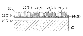
光反射部21は、図2に示すようにバンド20の表面に融着一体化された固着層23と、固着層23上に設けられ、光輝性材料24が分散配置された塗料層25と、塗料層25の表面に配列して少なくとも一部が埋設されたガラスビーズ26とを備える。光反射部21は、バンド20の基材部22の表面全周に渡って形成され、死角を生じることなく、光を再帰反射する。尚、再帰反射とは、入射した光が再び入射した方向と同じ方向に反射することをいう。
As shown in FIG. 2, the
固着層23は、バンド20の表面に融着一体化される。具体的には、固着層23は、ガラスビーズ26を支持すると共に、光反射部21をバンド20に強固に一体化する。固着層23は、例えばアクリル系、ウレタン系、塩化ビニル系、シリコン系、エポキシ系、酢酸ビニル系、ポリエステル系等の樹脂からなり、特にバンド20を構成する基材部22の材料と相溶性が高い樹脂を用いるとよい。
The
光輝性材料24は、塗料層25の内部に分散配置され、ガラスビーズ26を通過した光を反射する。光輝性材料24は、実質的に完全な反射性を有する材料や、一部の光を通過させる透過性のある反射材を用いることができる。また、透過性のある反射材は、塗料層25の着色による光の色づけが容易となる。さらに、光輝性材料24は、燐片状、粒子状、繊維状等に形成される。光輝性材料24の粒径は、塗料層25を構成する塗料等への分散性や反射機能に影響を及ぼし、本実施形態では、平均粒径0.1μm〜200μmとする。
The
具体的には、光輝性材料24としては、一般的にマイカが用いられる。ここで、マイカとは、雲母を薄い燐片状に加工したものをいう。マイカの反射光は、一般的に白色であって、当該マイカ表面に、酸化チタンや酸化鉄によって被覆することにより、反射性能が向上する。光輝性材料24としては、その他アルミニウム粒子やグリッターと呼ばれるメッキ、又は着色されたフィルムを約100μm×100μmの大きさに細分化された四角形状の微粒子を用いることができる。また、光輝性材料24を着色することにより、その着色された色の反射光を出すようにすることも可能である。
Specifically, mica is generally used as the
塗料層25に含まれる光輝性材料24の含有量は、光輝性材料の種類や要求性能によって異なるが、塗料層25の0〜90重量部に設定すると良く、さらに3〜20重量部に設定するとより好ましい。尚、光輝性材料24の含有量が多すぎると、着色成分が隠蔽され、色光が得られにくくなる。また、光輝性材料24の含有量が多すぎると、塗料層25を構成する塗料の割合が少なくなることから、塗料層25中に光輝性材料24を固定する力、また塗料層25の表面にガラスビーズ26を固定する力が弱まり、耐久性が低下する。
The content of the
塗料層25は、光輝性材料24を内包し、各種の顔料又は染料により着色された塗料から形成される。塗料層25は、ガラスビーズ26を確実に支持することができると共に、光輝性材料24の反射機能を良好に発揮することができる厚みに形成すると好ましい。具体的には、塗料層25は、厚さ10〜200μmに形成する。
The
ガラスビーズ26は、塗料層25の表面に配列して、少なくとも一部が埋設している。ガラスビーズ26は、一般的な各種ガラス材料から形成され、例えば酸化ナトリウム、酸化カルシウム、酸化ケイ素、酸化バリウム、酸化亜鉛、酸化チタン等を適宜配合することにより、再帰反射体として適した特性、例えば屈折率、融点等を満たすガラス材料から形成することが出来る。
The
屈折率としては、屈折率が1.5〜2.5の範囲であれば好ましく、特に屈折率1.93程度の場合、焦点位置は光が入射した位置の反対側のガラスビーズ26上に結ぶ構成となり、その焦点位置で反射した光がガラスビーズ26内部を通過し、外側へ出て行くため、良好な再帰反射機能を発揮する。また、融点は、約700度以上であればよく、好ましくは800度〜1000度であるとよい。
The refractive index is preferably in the range of 1.5 to 2.5. Particularly when the refractive index is about 1.93, the focal position is connected to the
また、ガラスビーズ26は、完全な球形、即ち真球状若しくはそれに近い形状で形成されるとよく、透明度が高いことが好ましい。さらに、ガラスビーズ26の粒径は、平均粒径1μm〜10mmの範囲であればよく、塗料層25への付着性、再帰反射機能等の条件を考慮して適宜変更可能である。
Further, the
ガラスビーズ26は、その性質上表面が水により被覆された状態では外部から入射する光が被覆した水を通過する際、屈折することにより焦点位置が変化し、再帰反射機能が低下する要因となる。そこで、ガラスビーズ26の表面に撥水加工や防汚加工を施すことにより、ガラスビーズ26の表面が水に被覆されにくくなるため、良好な再帰反射機能を維持することができる。
In the state where the surface of the
基材部22は、樹脂材料又は金属材料等から形成され、設置場所や用途に合わせて黄色や黒色等に着色することが可能である。本実施形態では、ポリエステル製であって、幅寸法10〜20mm程度の帯形状である。尚、その目的や用途に合わせて幅寸法は適宜変更可能である。
The
上述したように構成される光反射部21は、自動車や自転車等の前照灯などから入射した光を再帰反射させることが可能である。具体的には、光反射部21に対し、光が外部からガラスビーズ26に入射すると、複雑な経路、例えばガラスビーズ26の内面で反射したり、ガラスビーズ26を通過する際に屈折したり、ガラスビーズ26を通過し、光輝性材料24により反射した後、再びガラスビーズ26に入射したりする経路を経て、光が最初に入射した方向と同じ方向に反射する。
The
上述した光反射部21は、以下の方法により製造される。図3は、光反射部21の製造工程を示す断面説明図である。
The
先ず、図3(a)に示すように、仮支持シート50上にガラスビーズ26を一面に敷き詰めた後、光輝性材料24を含む塗料により、敷き詰めたガラスビーズ26をコーティングや印刷を施し、塗料層25を形成する。尚、本実施形態では、仮支持シート50としてポリエステルフィルムを用いる。また、仮支持シート50は、バンド20の形状や大きさに応じた大きさとするとよい。
First, as shown in FIG. 3A, after the
光輝性材料24を含む塗料により形成された塗料層25が乾燥した後、図3(b)に示すように塗料層25上に樹脂からなる固着層23を形成する。ここで、固着層23を形成する樹脂は、バンド20を構成する基材部22の材料と相溶性が高い樹脂を用いるとよい。本実施形態では、基材部22は帯形状のポリエステル製である。
After the
次に、図3(c)に示すように固着層23上にバンド20の基材部22を重ねあわせ、固着層23を形成する樹脂が溶融する温度まで加熱し、熱転写を実施する。熱転写後、十分に冷却し、固着層23を形成する樹脂を固化することにより、光反射部21は基材部22に融着一体化される。そして、仮支持シート50を取り除くことにより、ガラスビーズ26が露出し、図2に示す断面形状を有する光反射部21が製造される。
Next, as shown in FIG. 3C, the
留具30は、本体部31と、本体部31に対し、回動軸32を中心に回動自在なカバー部33とを有する。留具30は、例えば樹脂材料から形成されるとよい。
The
本体部31は、底面部31aと、底面部31aの両端部から立設された側面部31bとを有する。また、底面部31aには、バンド20の一端部を固定可能な本体側固定部34が設けられる。さらに、側面部31bには、カバー部33と係合可能な係合部が形成される。
The
本体側固定部34は、図4に示すように、バンド20の一端部が挿通される第1挿通孔34aと第2挿通孔34bとを備える。バンド20の一端部が第1、第2挿通孔34a、34bに挿通されることにより、バンド20の一端部は本体部31に容易に固定することができる。
As shown in FIG. 4, the main body
カバー部33は、バンド20の長手方向の寸法を調節し、且つバンド20の他端部を固定可能なカバー側固定部35を備える。具体的には、カバー側固定部35は、回動軸32近傍に挿通孔として設けられ、回動軸32に巻きつけられたバンド20の他端部が挿通され、バンド20の長手方向の寸法を調節した後、カバー部33が本体部31側に回動することにより、バンド20の他端部が回動軸32に固定される。尚、バンド20の長手方向の寸法を調節し、バンド20の他端部がカバー部33内部に収まるようにバンド20の他端部を図示しない切断手段により、切断するとよい。
The
また、カバー部33の両端部には、本体部31の係合部と係合可能な爪部36が形成される。カバー部33が本体部31側に回動し、爪部36が本体部31の係合部と係合することにより、カバー部33は本体部31に固定される。
Further, claw
上述した本実施形態の留具付反射バンド10を柱状体の取付対象物、例えば電柱に取り付ける手順について、説明する。図5は、本実施形態の留具付反射バンド10の使用状態を示す説明図である。
A procedure for attaching the above-described reflective band with
先ず、バンド20の一端部を留具30の本体側固定部34に固定したバンド20は、取付対象物、例えば電柱40に沿わせて、バンド20を電柱40に一巻きする。次に、図4(a)に示すようにカバー部33が開いた状態で、バンド20の他端部をカバー部33に設けられたカバー側固定部35である挿通孔に、バンド20が電柱40との間に弛みがないようにバンド20の長さを調節し、挿通する。そして、カバー部33を本体部31側に回動させ、図4(b)に示すようにカバー部33の爪部36が本体部31の係合部と係合することにより、カバー部33は本体部31に固定される。そして、図5を示すように留具付反射バンド10は、電柱40の任意の高さ位置に固定することができる。
First, the
本実施形態の留具付反射バンド10は、自動車や自転車からの光を再帰反射する光反射部21がバンド20の表面全周に形成されていることにより、光が入射する角度に影響されることがなく、入射光を再帰反射させることができ、自動車や自転車の運転手は電柱等の存在を確実に認識し、電柱等に対する衝突や接触を回避できる。また、本実施形態の留具付反射バンド10は、自動車が電柱等への衝突を回避できるため、電柱等の破損やそれによる停電を防止することができる。
The
本実施形態の留具付反射バンド10は、バンド20の表面に融着一体化された固着層23と、固着層23上に設けられ、光輝性材料24が分散配置された塗料層25と、塗料層25の表面に配列して少なくとも一部が埋設されたガラスビーズ26とを備えた簡単な構成により、自動車や自転車の前照灯などから入射された光を確実に再帰反射させることができる。
The reflector-equipped
本実施形態の留具付反射バンド10は、光反射部21を構成する固着層23がバンド20の表面に融着一体化されていることにより、長期間に渡り、屋外で太陽光や雨風にさらされても、また湾曲した状態で取付対象物、例えば電柱に設置された場合であっても、光反射部がバンドから剥がれにくくすることが可能となる。
The
本実施形態の留具付反射バンド10は、取付対象物、例えば電柱等の任意の位置に、ねじ回し等の工具を用いることなく、容易に取り付けることができる。また、本実施形態の留具付反射バンド10は、留具30が電柱の外周方向に突出しておらず、電柱の近くを通行する歩行者や自転車の運転手の接触を防止することができる。さらに、本実施形態の留具付反射バンド10を取付対象物に取付けた後、バンドがゆるむことがなく、最初に取付けた位置からずれることがない。
The reflector-equipped
本実施形態の留具付反射バンド10は、バンド20毎に留具30が設けられているため、設置場所や用途に応じて、取付対象物に取り付ける本数を調節することが可能である。また、複数取付けた留具付反射バンド10の内、破損した留具付反射バンド10のみ取り替えることができ、経済的である。
In the
〔実施形態の変形例等〕
本明細書開示の発明は、上記本実施形態の構成の他に、適用可能な範囲で、これらの部分的な構成を本明細書開示の他の構成に変更して特定したもの、或いはこれらの構成に本明細書開示の他の構成を付加して特定したもの、或いはこれらの部分的な構成を部分的な作用効果が得られる限度で削除して特定した上位概念化したものを含み、下記の変形例等も包含する。
[Modifications of Embodiment, etc.]
In addition to the configuration of the present embodiment described above, the invention disclosed in the present specification may be specified by changing these partial configurations to other configurations disclosed in the present specification, to the extent applicable. Including those specified by adding other configurations disclosed in the present specification to the configuration, or those obtained by deleting these partial configurations to the extent that partial effects can be obtained, Modifications and the like are also included.
本発明の留具付反射バンド10は、電柱に限られず、街路灯や橋の欄干、ガードパイプ、車止め等の屋外で利用することが可能であり、また工場や立体駐車場等の施設内に設けられた支柱に取り付け、施設内識別標識として利用することもできる。
The reflector-equipped
10…留具付反射バンド
20…バンド
21…光反射部
22…基材部
23…固着層
24…光輝性材料
25…塗料層
26…ガラスビーズ
30…留具
31…本体部
31a…底面部
31b…側面部
32…回動軸
33…カバー部
34…本体側固定部
34a…第1挿通孔
34b…第2挿通孔
35…カバー側固定部
36…爪部
40…電柱
50…仮支持シート
DESCRIPTION OF
Claims (4)
前記バンドを柱状体の取付対象物に取付可能な留具とを有し、
前記光反射部は熱転写されることにより形成されることを特徴とする留具付反射バンド。 A band in which a light reflecting portion for retroreflecting light is formed all over the surface;
A fastener capable of attaching the band to an attachment object of a columnar body,
The reflection band with a fastener, wherein the light reflection portion is formed by thermal transfer.
仮支持シート上に敷き詰められた前記ガラスビーズを、前記光輝性材料が含まれた塗料によりコーティングして前記塗料層を形成する工程と、
前記塗料層を乾燥する工程と、
前記塗料層上に前記バンドの材料と相溶性が高い樹脂からなる前記固着層を形成する工程と、
前記固着層上に前記バンドを重ね合わせ、前記固着層の樹脂が溶融する温度まで加熱し、熱転写する工程と、
前記固着層の樹脂を冷却固化した後、前記仮支持シートを取り除く工程とを有する方法によって製造されることを特徴とする留具付反射バンド。 The light reflecting portion according to claim 2,
Coating the glass beads spread on a temporary support sheet with a paint containing the glittering material to form the paint layer;
Drying the paint layer;
Forming the fixing layer made of a resin highly compatible with the material of the band on the paint layer;
Superimposing the band on the fixing layer, heating to a temperature at which the resin of the fixing layer melts, and thermally transferring;
A reflective band with a fastener, which is manufactured by a method including a step of cooling and solidifying a resin of the fixing layer and then removing the temporary support sheet.
Priority Applications (1)
| Application Number | Priority Date | Filing Date | Title |
|---|---|---|---|
| JP2014127903A JP2016008997A (en) | 2014-06-23 | 2014-06-23 | Reflection band with retainer |
Applications Claiming Priority (1)
| Application Number | Priority Date | Filing Date | Title |
|---|---|---|---|
| JP2014127903A JP2016008997A (en) | 2014-06-23 | 2014-06-23 | Reflection band with retainer |
Publications (1)
| Publication Number | Publication Date |
|---|---|
| JP2016008997A true JP2016008997A (en) | 2016-01-18 |
Family
ID=55226606
Family Applications (1)
| Application Number | Title | Priority Date | Filing Date |
|---|---|---|---|
| JP2014127903A Pending JP2016008997A (en) | 2014-06-23 | 2014-06-23 | Reflection band with retainer |
Country Status (1)
| Country | Link |
|---|---|
| JP (1) | JP2016008997A (en) |
Citations (5)
| Publication number | Priority date | Publication date | Assignee | Title |
|---|---|---|---|---|
| JP2001348823A (en) * | 2000-06-05 | 2001-12-21 | Nichido Denko Kk | Light reflection type band marker |
| US20030012599A1 (en) * | 2001-06-29 | 2003-01-16 | Magnus Wallgren | Markings on roads with a fixed road surface, such as asphalt, concrete or the like for motor vehicles |
| JP2003502707A (en) * | 1999-06-17 | 2003-01-21 | スリーエム イノベイティブ プロパティズ カンパニー | Retroreflective article having a reflective layer and a colored layer containing a dye covalently bonded to a polymer |
| JP2004252117A (en) * | 2003-02-20 | 2004-09-09 | Unitika Sparklite Kk | Thermal transfer retroreflection medium intermediary body and thermal transfer method using the body |
| JP2011206655A (en) * | 2010-03-29 | 2011-10-20 | Komatsu Process:Kk | Coating method and retroreflective coating material used for the same |
-
2014
- 2014-06-23 JP JP2014127903A patent/JP2016008997A/en active Pending
Patent Citations (5)
| Publication number | Priority date | Publication date | Assignee | Title |
|---|---|---|---|---|
| JP2003502707A (en) * | 1999-06-17 | 2003-01-21 | スリーエム イノベイティブ プロパティズ カンパニー | Retroreflective article having a reflective layer and a colored layer containing a dye covalently bonded to a polymer |
| JP2001348823A (en) * | 2000-06-05 | 2001-12-21 | Nichido Denko Kk | Light reflection type band marker |
| US20030012599A1 (en) * | 2001-06-29 | 2003-01-16 | Magnus Wallgren | Markings on roads with a fixed road surface, such as asphalt, concrete or the like for motor vehicles |
| JP2004252117A (en) * | 2003-02-20 | 2004-09-09 | Unitika Sparklite Kk | Thermal transfer retroreflection medium intermediary body and thermal transfer method using the body |
| JP2011206655A (en) * | 2010-03-29 | 2011-10-20 | Komatsu Process:Kk | Coating method and retroreflective coating material used for the same |
Similar Documents
| Publication | Publication Date | Title |
|---|---|---|
| JP3717938B2 (en) | Wet retroreflective marker material | |
| KR100614059B1 (en) | Article exhibiting dry and wet retroreflectivity | |
| AU665055B2 (en) | Retroreflective assembly and process for making same | |
| JP2000515207A (en) | High-angle retroreflective products with spherical refractive elements | |
| US20110059295A1 (en) | Retroreflective pavement marking with improve performance in wet night conditions | |
| CZ58993A3 (en) | Light-reflecting bodies, particularly for marking roads | |
| KR101675377B1 (en) | Solar reflective and photoluminescent expression road stud | |
| KR101160583B1 (en) | Reflector and road marker including the same | |
| JP2016008997A (en) | Reflection band with retainer | |
| JP4099318B2 (en) | Reflector for sticking the support | |
| JP4762916B2 (en) | Retroreflective sheet and method for producing and using the same | |
| BRPI0506984B1 (en) | floor marking and retroreflective element | |
| JP2003171914A (en) | Road marking and road marking sheet | |
| JP4704940B2 (en) | Road marking object | |
| JP2007277935A (en) | Indicating body for road | |
| KR101750220B1 (en) | The sheet type panel of pillar plate for preventing adhesion of illegal advertisements | |
| US20140144370A1 (en) | Reflector for marking a road surface and method for manufacturing same | |
| JP2004027784A (en) | Road sign | |
| JP2011063960A (en) | Road sign body | |
| JP2006284888A (en) | Retroreflection sheet including information display region color-developed by ultraviolet excitation | |
| KR200271330Y1 (en) | Road safety sign bottle with body | |
| CA2212021A1 (en) | Bicycle tires having retroflective surfaces | |
| JP2003206513A (en) | Retroreflection member and road marking body | |
| JP3576381B2 (en) | Prop with reflector and protective fence | |
| JP3664243B2 (en) | Retroreflective composition containing retroreflective microcapsules |
Legal Events
| Date | Code | Title | Description |
|---|---|---|---|
| A621 | Written request for application examination |
Free format text: JAPANESE INTERMEDIATE CODE: A621 Effective date: 20170530 |
|
| A131 | Notification of reasons for refusal |
Free format text: JAPANESE INTERMEDIATE CODE: A131 Effective date: 20180307 |
|
| A977 | Report on retrieval |
Free format text: JAPANESE INTERMEDIATE CODE: A971007 Effective date: 20180309 |
|
| A02 | Decision of refusal |
Free format text: JAPANESE INTERMEDIATE CODE: A02 Effective date: 20180905 |
|
| A711 | Notification of change in applicant |
Free format text: JAPANESE INTERMEDIATE CODE: A711 Effective date: 20181017 |
|
| A521 | Request for written amendment filed |
Free format text: JAPANESE INTERMEDIATE CODE: A821 Effective date: 20181017 |
|
| A521 | Request for written amendment filed |
Free format text: JAPANESE INTERMEDIATE CODE: A821 Effective date: 20181017 |